EP3260284A1 - Procede de reparation d'un radome utilisant le radome comme enceinte de chauffage et outil pour sa mise en oeuvre - Google Patents
Procede de reparation d'un radome utilisant le radome comme enceinte de chauffage et outil pour sa mise en oeuvre Download PDFInfo
- Publication number
- EP3260284A1 EP3260284A1 EP17173197.9A EP17173197A EP3260284A1 EP 3260284 A1 EP3260284 A1 EP 3260284A1 EP 17173197 A EP17173197 A EP 17173197A EP 3260284 A1 EP3260284 A1 EP 3260284A1
- Authority
- EP
- European Patent Office
- Prior art keywords
- radome
- repair
- panel
- enclosure
- heating
- Prior art date
- Legal status (The legal status is an assumption and is not a legal conclusion. Google has not performed a legal analysis and makes no representation as to the accuracy of the status listed.)
- Granted
Links
Images
Classifications
-
- B—PERFORMING OPERATIONS; TRANSPORTING
- B29—WORKING OF PLASTICS; WORKING OF SUBSTANCES IN A PLASTIC STATE IN GENERAL
- B29C—SHAPING OR JOINING OF PLASTICS; SHAPING OF MATERIAL IN A PLASTIC STATE, NOT OTHERWISE PROVIDED FOR; AFTER-TREATMENT OF THE SHAPED PRODUCTS, e.g. REPAIRING
- B29C65/00—Joining or sealing of preformed parts, e.g. welding of plastics materials; Apparatus therefor
- B29C65/02—Joining or sealing of preformed parts, e.g. welding of plastics materials; Apparatus therefor by heating, with or without pressure
-
- B—PERFORMING OPERATIONS; TRANSPORTING
- B29—WORKING OF PLASTICS; WORKING OF SUBSTANCES IN A PLASTIC STATE IN GENERAL
- B29C—SHAPING OR JOINING OF PLASTICS; SHAPING OF MATERIAL IN A PLASTIC STATE, NOT OTHERWISE PROVIDED FOR; AFTER-TREATMENT OF THE SHAPED PRODUCTS, e.g. REPAIRING
- B29C73/00—Repairing of articles made from plastics or substances in a plastic state, e.g. of articles shaped or produced by using techniques covered by this subclass or subclass B29D
- B29C73/04—Repairing of articles made from plastics or substances in a plastic state, e.g. of articles shaped or produced by using techniques covered by this subclass or subclass B29D using preformed elements
- B29C73/10—Repairing of articles made from plastics or substances in a plastic state, e.g. of articles shaped or produced by using techniques covered by this subclass or subclass B29D using preformed elements using patches sealing on the surface of the article
-
- B—PERFORMING OPERATIONS; TRANSPORTING
- B29—WORKING OF PLASTICS; WORKING OF SUBSTANCES IN A PLASTIC STATE IN GENERAL
- B29C—SHAPING OR JOINING OF PLASTICS; SHAPING OF MATERIAL IN A PLASTIC STATE, NOT OTHERWISE PROVIDED FOR; AFTER-TREATMENT OF THE SHAPED PRODUCTS, e.g. REPAIRING
- B29C65/00—Joining or sealing of preformed parts, e.g. welding of plastics materials; Apparatus therefor
- B29C65/48—Joining or sealing of preformed parts, e.g. welding of plastics materials; Apparatus therefor using adhesives, i.e. using supplementary joining material; solvent bonding
-
- B—PERFORMING OPERATIONS; TRANSPORTING
- B29—WORKING OF PLASTICS; WORKING OF SUBSTANCES IN A PLASTIC STATE IN GENERAL
- B29C—SHAPING OR JOINING OF PLASTICS; SHAPING OF MATERIAL IN A PLASTIC STATE, NOT OTHERWISE PROVIDED FOR; AFTER-TREATMENT OF THE SHAPED PRODUCTS, e.g. REPAIRING
- B29C66/00—General aspects of processes or apparatus for joining preformed parts
- B29C66/80—General aspects of machine operations or constructions and parts thereof
-
- B—PERFORMING OPERATIONS; TRANSPORTING
- B29—WORKING OF PLASTICS; WORKING OF SUBSTANCES IN A PLASTIC STATE IN GENERAL
- B29C—SHAPING OR JOINING OF PLASTICS; SHAPING OF MATERIAL IN A PLASTIC STATE, NOT OTHERWISE PROVIDED FOR; AFTER-TREATMENT OF THE SHAPED PRODUCTS, e.g. REPAIRING
- B29C73/00—Repairing of articles made from plastics or substances in a plastic state, e.g. of articles shaped or produced by using techniques covered by this subclass or subclass B29D
- B29C73/04—Repairing of articles made from plastics or substances in a plastic state, e.g. of articles shaped or produced by using techniques covered by this subclass or subclass B29D using preformed elements
- B29C73/10—Repairing of articles made from plastics or substances in a plastic state, e.g. of articles shaped or produced by using techniques covered by this subclass or subclass B29D using preformed elements using patches sealing on the surface of the article
- B29C73/12—Apparatus therefor, e.g. for applying
-
- B—PERFORMING OPERATIONS; TRANSPORTING
- B29—WORKING OF PLASTICS; WORKING OF SUBSTANCES IN A PLASTIC STATE IN GENERAL
- B29C—SHAPING OR JOINING OF PLASTICS; SHAPING OF MATERIAL IN A PLASTIC STATE, NOT OTHERWISE PROVIDED FOR; AFTER-TREATMENT OF THE SHAPED PRODUCTS, e.g. REPAIRING
- B29C73/00—Repairing of articles made from plastics or substances in a plastic state, e.g. of articles shaped or produced by using techniques covered by this subclass or subclass B29D
- B29C73/24—Apparatus or accessories not otherwise provided for
- B29C73/30—Apparatus or accessories not otherwise provided for for local pressing or local heating
- B29C73/34—Apparatus or accessories not otherwise provided for for local pressing or local heating for local heating
-
- B—PERFORMING OPERATIONS; TRANSPORTING
- B64—AIRCRAFT; AVIATION; COSMONAUTICS
- B64F—GROUND OR AIRCRAFT-CARRIER-DECK INSTALLATIONS SPECIALLY ADAPTED FOR USE IN CONNECTION WITH AIRCRAFT; DESIGNING, MANUFACTURING, ASSEMBLING, CLEANING, MAINTAINING OR REPAIRING AIRCRAFT, NOT OTHERWISE PROVIDED FOR; HANDLING, TRANSPORTING, TESTING OR INSPECTING AIRCRAFT COMPONENTS, NOT OTHERWISE PROVIDED FOR
- B64F5/00—Designing, manufacturing, assembling, cleaning, maintaining or repairing aircraft, not otherwise provided for; Handling, transporting, testing or inspecting aircraft components, not otherwise provided for
- B64F5/40—Maintaining or repairing aircraft
-
- B—PERFORMING OPERATIONS; TRANSPORTING
- B29—WORKING OF PLASTICS; WORKING OF SUBSTANCES IN A PLASTIC STATE IN GENERAL
- B29L—INDEXING SCHEME ASSOCIATED WITH SUBCLASS B29C, RELATING TO PARTICULAR ARTICLES
- B29L2031/00—Other particular articles
- B29L2031/30—Vehicles, e.g. ships or aircraft, or body parts thereof
- B29L2031/3076—Aircrafts
-
- B—PERFORMING OPERATIONS; TRANSPORTING
- B29—WORKING OF PLASTICS; WORKING OF SUBSTANCES IN A PLASTIC STATE IN GENERAL
- B29L—INDEXING SCHEME ASSOCIATED WITH SUBCLASS B29C, RELATING TO PARTICULAR ARTICLES
- B29L2031/00—Other particular articles
- B29L2031/60—Multitubular or multicompartmented articles, e.g. honeycomb
- B29L2031/608—Honeycomb structures
Definitions
- the present invention relates to the field of radome repair methods including aircraft radome composite material and the tooling used to perform this type of repair.
- the radome has the particular function of protecting a radar and has a structure of material permeable to electromagnetic waves and for example composite material.
- the structure of the radome may be damaged by various types of incidents such as bird strike or hail and may be subject to sinking, tearing, scratching or other deterioration requiring repair.
- FR2953812 shows an example of repair of a composite fuselage. As presented in the application, it is necessary to make a cut around the deteriorated area to remove it and to place a doubler at the opening made by cutting that is fixed by baking in the case of a thermosetting resin .
- the radome In the case of the radome, to carry out the polymerization, the radome is removed from the aircraft and placed in a heating chamber such as an autoclave, an oven or the like. Or the frame at the free end of the composite radome and allowing attachment with the fuselage of the aircraft and other elements of the radome are made in some aircraft in metallic material, material which does not support the temperature necessary for the polymerization of the resin (more than 60 ° C).
- the present invention aims to propose a repair method and a tool for implementing this method to overcome the problem of time and difficulty to remove all the metal parts of a radome and to transport the radome and access suitable heating enclosures.
- the method consists in using the radome itself as a heating chamber so as to avoid the use of an autoclave and the dismantling of certain parts of the radome that do not support the necessary cooking temperature.
- the repair method has at least one of the following optional features, taken alone or in combination.
- the method comprises a step of preparing said damaged area by cutting and inserting replacement elements into the cutouts that are required to be fired for fixing said elements to the panel.
- the heating step includes detecting at least one temperature inside the heating chamber to control the heating of said enclosure so as to achieve a repair temperature.
- the method comprises a step of mixing the air contained in said enclosure.
- the method comprises a step of deploying a deployable seal between the cover and the panel for sealing said repair enclosure.
- It comprises a step of holding the cover by placing at least one elongated shim, one end of which bears against the outer face of the cover and the other end of which bears against a fixed structure.
- It includes a step of setting up the panel support means to facilitate access to the heating chamber.
- It comprises a step of placing an insulating cover on at least a portion of the outer face of the radome panel.
- the present invention also relates to the repair tool of a radome comprising a panel having a double curvature forming a dome, said panel having at least one damaged area characterized in that the tool comprises the panel itself, a cover for closing an interior space of the radome panel to form an enclosure, called a repair enclosure, the surface of the radome panel forming said repair enclosure containing said damaged area and heating means for heating the interior space of said repair enclosure forming and a heating chamber for cooking expected for the repair of the damaged area.
- the tool has at least one of the following optional features, taken alone or in combination.
- the cover is formed of a single block and has a shape whose contour corresponds to the inner contour of the panel against which it must apply.
- the heating means are in the form of a hot air generating device that can be removably integrated into the cover and pass through an orifice provided for this purpose.
- the tool comprises means for mixing air.
- the free peripheral edge of the hood includes a deployable seal.
- Temperature detection means are provided inside the repair enclosure, the detection means being coupled to a control center of the heating means of the repair enclosure.
- the tool comprises at least one elongated shim, one end of which bears against the outer face of the hood and the other end of which bears against a fixed structure.
- the present invention relates to a method of repairing a radome 1 and more particularly in the example described below of an aircraft radome.
- the radome 1 comprises a panel 2 made of material permeable to electromagnetic waves and for example composite material.
- the panel 2 has a double curvature so as to form a domed concavity.
- the free peripheral edge 3 of the radome 1 is joined, in general so articulated, by any type of known means to the rest of the fuselage of the aircraft. In the description which follows, it is considered that the radome has been dismounted and removed from the aircraft as shown on the Figures 1 and 2 .
- the panel 2 has an inner face 4 and an outer face 5.
- the internal face 4 of the panel is hollow.
- the free peripheral edge 3 or at least part of the edge belongs to a plane P: as a result, the radome may rest against a flat surface and in particular on the ground by its peripheral edge 3 or the part belonging to the plane P of this, the part in question of the edge 3 being large enough to do this.
- the radome 1 will not be described in more detail: it may include other components such as arrester strips or others whose description is not necessary to present the method and the repair tool.
- the panel 2 because of its exposure to the front end of the aircraft suffers damage that must be repaired.
- the repair process comprises several steps, the first of which is to reconstruct the panel 2 of the radome 1 on a damaged area 7.
- a cutting according to a known type of procedure is performed to remove the damaged area 7 and replacement elements come to fill the cutout operated.
- the composite panel 2 results from the superposition of a number of plies on the side of the inner face 4, a honeycomb layer and a number of plies on the side of the outer face 5.
- the folds of the panel 2 are cut, the cuts being of decreasing size from the internal face 4 to the outer face 5.
- the honeycomb layer is also cut in the same contour as the fold closest to said layer on the side of the outer face.
- the folds and the honeycomb layer are then reconstituted: a first composite part of repair whose shape of the contour is identical to that of the contour of the cut the fold on the outer face 5 and slightly smaller dimension is inserted inside said cut.
- a second piece of larger size than the previous piece whose contour shape is identical to the shape of the contour of the cut of the fold closest to the previous one and of a very slightly smaller dimension is inserted inside the cutout of this second fold and so on until the honeycomb layer.
- a repair honeycomb portion is inserted inside the cut of the honeycomb layer: a layer of glue is provided on the underside and upper side of the honeycomb layer for bonding with the nearest folds. We then resume the insertion of parts in the contours of the folds to the inner face 4.
- the method comprises a heating step of the radome and more particularly of the damaged zone 7 to ensure the cooking allowing the fixing of the repair parts and repair honeycomb portion to the cut radome panel 2 .
- the repair process uses the concavity of the radome 1 to make it a heating chamber.
- an interior space of the dome formed by the radome panel 2 is closed by an insulating cover 8 to form an enclosure 9, called a repair enclosure.
- the surface of the panel 2 forming said repair enclosure 9 contains the damaged area 7 to be repaired and does not contain the free peripheral edge 3.
- the insulating cover 8 is formed in a single block which facilitates its movement and its placement inside the radome.
- the contour of the cover 8 has a shape corresponding to that of the inner contour of the radome on which it is applied. Thus, it is sufficient to grasp the hood, to move it to introduce it inside the radome against the inner face 4 of which it comes to apply to form the heating chamber.
- the repair enclosure becomes a heating chamber. Heating is carried out at a cooking temperature such that the surface of the panel 2 forming part of the repair enclosure is not impacted contrary to zone 7.
- the polymerization of a composite panel is effected at a temperature called T1 cooking. To carry out the repair, it is not necessary to reach the cooking temperature T1. It suffices to reach a temperature T2 lower than the temperature T1 of cooking and to maintain it for a longer time than that necessary for cooking.
- the procedure used to repair a panel in the autoclave or oven-type heating chambers consists of heating the damaged zone 7 to a repair temperature T2 less than the cooking temperature T1 and for a longer time than that required for the treatment. polymerization of a panel. The same procedure is used in the heating chamber 9.
- the panel 2 in its entirety can thus withstand heat to perform its function as a heating chamber 9.
- the free peripheral edge 3 being outside the heating chamber 9, it is not necessary to dismantle the metal frame or all the other elements that are fixed on the edge 3 to interface with the remainder of the fuselage or on the surface of the panel 2 between the free peripheral edge and the hood.
- the method thus makes it possible to use the radome itself as a heating enclosure.
- the heating step may comprise detecting at least one temperature inside the heating chamber 9 to control the heating of said chamber to the repair temperature T2.
- At least one temperature measurement sensor 10 is installed on the internal face 4 of the panel 2 belonging to the enclosure 9 or the cover 8 and transmits the detected temperature (s) to a control center 11 outside the enclosure 9 heating. An operator can thus view the temperature reached in different locations of the heating chamber 9, check the value and homogeneity if several temperatures have been measured and regulate the heating if necessary. This regulation can also be performed automatically.
- the use of several sensors 10 makes it possible to check the homogeneity of the temperature in the enclosure 9. It also has the function of ensuring the measurement in the event of failure of one of the sensors or of detecting the failure of a sensor. through isolated false measures.
- the sensors are arranged near the damaged zone 7. Indeed, it is necessary to reach the repair temperature T2 at the zone 7 but not essential anywhere else in the enclosure 9.
- the method may comprise a step of mixing the air contained in the enclosure 9 of repair.
- the stirring of the air engages with the start of the heating but it can start before or after the start of heating.
- the purpose of mixing the air is to homogenize the distribution of hot air in the heating chamber to ensure the same polymerization conditions over the entire surface of the damaged zone 7.
- the method may comprise a step of deploying a seal 12 deployable between the cover 8 and the panel 2 for sealing said repair chamber 9.
- the deployment of the seal 12 is activated by blowing, inflation, mechanical actuation or any other type of action allowing it. Deployment of the seal ensures isolation of the joint between the cover 8 and the panel 2.
- the peripheral edge of the hood 8 is provided with the gasket 12.
- the gasket 12 unfolds by deformation and more precisely in the embodiment illustrated by inflation.
- the seal extends outward from the cover 8 in the direction of the panel 2 once the cover is installed.
- the seal is applied to the panel 2 and ensures a hermetic closure of the heating chamber 9. Once the repair is completed, it is possible to reinsert the seal in the hood manually or by suction.
- a deployable seal 12 can allow the adaptation of the hood with various shapes or sizes of radome panels 2.
- the cover 8 does not need to have dimensions in perfect correspondence with that of the panel 2.
- a seal 12 deployable it is suitable for several types, shapes, sizes of radome.
- the method has a step of holding the cover in place to form a heating chamber 9. This step can be combined with the previous step of sealing the enclosure: indeed, the seal may have a function of adhesion such that it holds the cover in place.
- the holding step may also precede or follow the step of deploying the seal.
- the hood can be held in place in a variety of ways.
- the method consists in using removable fastening systems of Scotch type, "VELCRO" (registered trademark), screw / nut or other. These systems join the outer face 13 of the free peripheral edge of the cover to the inner face 4 of the panel.
- the method consists in the establishment of a removable fastening system in the form of at least one elongated shim 14, one end bears on the outer face 13 of the hood and the other end is supported on a structure fixed to allow the hood to be held.
- the fixed structure can be of any kind the floor, a wall, a platform or even the radome itself.
- the fixed structure consists of the structure of the radome proper.
- the process can therefore be carried out where, on any surface.
- the shim is supported for example on the metal frame fixed at the free peripheral edge 3 of the panel 2 to maintain the other end of the hood to which it is attached.
- the number of shims is determined as required, the shims being distributed in a balanced manner on the surface of the hood.
- Removable fixing systems can combine; for example, tape can be used to ensure a first reinforced holding by adding shims.
- the method comprises a step of setting up means 16 for supporting the panel 2 to facilitate access to the heating chamber 9.
- the panel 2 is maintained in height by means of a support 16.
- the support is in the form of a single central foot flared at its lower end to support stably on the surface on which it rests.
- the foot and the flared base may have various shapes as will be described later.
- the foot is unique here but like a table, the support can include more than one foot or be in any other form.
- the method may have a step of placing a thermally insulating cover 17 to cover the outer face of the radome panel 2.
- the insulating cover 17 accelerates the rise in temperature and reinforces the thermal insulation of the heating chamber 9.
- the repair method thus offers the advantages of avoiding the use of heavy means such as autoclave or oven, having to disassemble radome components such as the frame 15 at the free peripheral edge of the panel 2, to transport the radome over long distances.
- the process can be operated quickly, simply and anywhere. It can be applied to all types of radome.
- the repair method requires the use of a tool presented in these main principles with the above description of the process and in more detail in the following.
- the tool comprises the cover 8 for closing the panel 2 of the radome.
- the cover 8 thus has a shape in correspondence with that of the panel 2 and more precisely the dome formed by the inner face 4 of the panel 2. If the panel 2 is semi-spherical, the cover 8 is in the form of a disc.
- the cover has an orifice 18 made for example in the center of its surface, namely for a disc in the center of the disc. The orifice 18 may be provided elsewhere than in the center of the hood ( Figures 1 and 2 ).
- the cover 8 has a flat surface whose free peripheral edge 3 comes into contact with the inner face 4 of the panel 2.
- the hood comprises two panels, an upper panel 19 and a lower panel 20 of composite material. The two panels are separated by a thermally insulating foam layer 21.
- hood with no flat surface.
- the flat surface is in many cases of configuration the most optimized surface to facilitate installation.
- the peripheral edge of the hood is provided with the seal 12 deployable.
- the seal 12 may be deployed by deformation, mechanical sliding-type retraction or the like. In the illustrated embodiment, the deployment is by deformation and more precisely by inflation.
- the seal 12 is in the form of an air chamber housed inside the peripheral edge of the cover over the entire perimeter.
- An air inlet 22 is provided in the air chamber, access to which is provided by a valve 23 accessible from the external face 13 of the hood. By performing an inflation at said valve 23, the air chamber fills with air and is deformed.
- the outer peripheral edges of the lower panel and upper panel 19 are not joined so as to allow free access to the expansion of the air chamber out of the hood, outwardly thereof.
- "VELCRO" (registered trademark) flanges may be provided on the periphery of the cover to prevent the seal 12 from coming out of its housing during storage or transport. The flanges are released during the installation of the hood.
- the size of the air chamber is such that when inflated, it comes into contact and apply or stick by pressure to the inner face of the panel 2 to ensure the hermetic closure of the repair enclosure.
- the shape and size of the hood are determined with respect to the shape and size of the radomes on which it is intended to be applied and with respect to the presence and shape of said gasket. It can also be provided to achieve suction by the valve 23 with a known type of suction device to put the seal 12 inside the hood.
- the repair tool comprises heating means 24 for heating the interior space of said repair chamber 9 forming the heating chamber and allowing the cooking expected for the repair of the damaged zone 7.
- the heating means 24 are in the form of a device 25 for generating hot air that can be removably integrated into the hood.
- the heating means are, for example, in the form of a hot-air gun, the duct 26 expelling the hot air is introduced into the orifice 18 provided in the center of the hood.
- the hot air generation device 25 is removably attached to the hood, for example by means of flanges. Any other type of attachment can be used.
- the tool comprises means for mixing air.
- the stirring means are in the form of an electric fan 27.
- the stirring means could also be in the form of a mechanical deflector. It can be arranged and fixed inside the enclosure 9 by any type of known means.
- the fan 9 is associated with the expulsion conduit 26 of the hot air generation device. Thus it is closer to the latter and allows optimized mixing.
- the propeller has a shape such that it also acts as a deflector.
- the deflector may also be independent of the propeller and for example be in the form of a perforated sheet placed at a distance from the outlet of the heating means and in the example described of the hot air gun.
- the deflector makes it possible to avoid a hot spot to the right of the gun, to distribute in an optimized manner and homogenized the temperature in the heating chamber.
- the repair tool of the radome comprises at least one elongate shim 14 whose one end bears on the outer surface of the cover and whose other end is supported on a fixed structure to allow the maintenance of the cover.
- the fixed structure is the frame 15 fixed on the free peripheral edge 3 of the panel 2.
- the wedge 14 runs along the inner face of the panel 2 between the frame and the outer face of the cover. The holds are distributed all around the periphery of the cover.
- the shims are fixed to the outer face of the cover using any articulated joining system 28 of known type.
- the radome To improve the insulation, it is also possible to cover the radome with an insulating cover 17. It must be of such shape that it completely covers the outer face of the radome panel 2 or at least up to the level of the cover 8.
- the cover 17 is made of an insulating material of known type.
- the repair tool may include support means 16 for facilitating access to the heating chamber. These means are not necessary. Indeed, once all the components of the tool in place, the radome can rest on the ground or any other surface and the control of heating is provided through the control center 11 may be external and remote from the radome.
- the figure 1 illustrates an embodiment of the support means.
- the support means are in the form of a support 16 of the foot table type.
- a single foot 16 is provided taking one end supported on the ground via a base 29 of stabilization and the other end supporting the hood at its center.
- the foot is fixed removably or not to the hood.
- the foot is for example of cylindrical shape, circular section, rectangular or other.
- the base 29 is for example conical, pyramidal or other.
- the support 16 may have more than one foot to distribute them around the center of the hood, leaving the free center for the installation of the means of heater.
- the repair tool may comprise temperature detection means provided inside the repair enclosure, the detection means being coupled to the control center 11 of the heating means of the repair enclosure.
- the detection means are in the form of measuring sensors such as thermocouples.
- the detection means comprise at least one sensor.
- the sensor or sensors 10 are arranged inside the repair / heating enclosure and more particularly as illustrated by FIG. figure 1 on the inside of the radome. In the example of the figure 1 , three sensors are represented.
- the sensors are connected to the control center outside the radome by a connection 30 for example of the wired type that can be passed through the central orifice, from outside the cover (between the cover and the panel 2 radome) or by complementary holes provided in the hood.
- the external control center 11 is in the form of a case for displaying the measured data and for controlling the means for heating and stirring / deflecting the air contained in the heating chamber. To do this, the control center is also connected by a connection 31, for example of the wired type to the heating means and the air mixing and deflection means.
Landscapes
- Engineering & Computer Science (AREA)
- Mechanical Engineering (AREA)
- Manufacturing & Machinery (AREA)
- Transportation (AREA)
- Aviation & Aerospace Engineering (AREA)
- Details Of Aerials (AREA)
Abstract
Description
- La présente invention concerne le domaine des procédés de réparation de radôme et notamment de radôme d'aéronef en matériau composite ainsi que de l'outillage utilisé pour réaliser ce type de réparation.
- La plupart des aéronefs et en particulier les avions de transport commerciaux comprennent un radôme situé en pointe avant. Le radôme a notamment pour fonction de protéger un radar et présente une structure en matériau perméable aux ondes électromagnétiques et par exemple en matériau composite. La structure du radôme peut se trouver endommager par des incidents de types divers tels qu'un impact d'oiseau ou la grêle et présenter un enfoncement, une déchirure, des rayures ou tout autre détérioration nécessitant une réparation.
- La demande de
brevet FR2953812 - Dans le cas du radôme, pour réaliser la polymérisation, on retire le radôme de l'aéronef et on le place dans une enceinte de chauffage telle qu'un autoclave, une étuve ou autre. Or le cadre se trouvant à l'extrémité libre du radôme en composite et permettant la fixation avec le fuselage de l'aéronef ainsi que d'autres éléments du radôme sont réalisés dans certains aéronefs en matériau métallique, matériau qui ne supporte pas la température nécessaire à la polymérisation de la résine (plus de 60°C).
- Cela implique de démonter toutes les parties métalliques du radôme et en particulier le cadre réalisant l'interface avec le fuselage avant de procéder à la cuisson. Il en résulte une augmentation importante du temps de réparation due uniquement au démontage de ces parties métalliques et un procédé de réparation lourd et contraignant nécessitant notamment le transport du radôme et l'accès à des enceintes de chauffage distantes.
- La présente invention a pour but de proposer un procédé de réparation et un outil de mise en oeuvre de ce procédé permettant de pallier au problème du temps et de la difficulté pour retirer l'ensemble des pièces métalliques d'un radôme ainsi que pour transporter le radôme et accéder à des enceintes de chauffage adaptées.
- Pour ce faire, la présente invention concerne un procédé de réparation d'un radôme comprenant un panneau présentant une double courbure formant dôme, ledit panneau comportant au moins une zone endommagée caractérisé en ce qu'il comprend les étapes suivantes :
- fermeture d'un espace intérieur du panneau par un capot pour former une enceinte, appelée enceinte de réparation, la surface du panneau formant ladite enceinte de réparation contenant ladite zone endommagée ;
- chauffage de l'espace intérieur à ladite enceinte de réparation formant ainsi une enceinte de chauffage permettant la cuisson attendue pour la réparation de la zone endommagée.
- Le procédé consiste en l'utilisation du radôme proprement dit comme enceinte de chauffage de manière à éviter le recours à un autoclave et le démontage de certaines parties du radôme ne supportant pas la température de cuisson nécessaire.
- Le procédé de réparation présente au moins l'une des caractéristiques optionnelles suivantes, prises isolément ou en combinaison.
- Le procédé comprend une étape de préparation de ladite zone endommagée par découpe et insertion d'éléments de remplacement dans les découpes opérées nécessitant une cuisson pour la fixation desdits éléments au panneau.
- L'étape de chauffage comprend la détection d'au moins une température à l'intérieur de l'enceinte de chauffage pour contrôler le chauffage de ladite enceinte de manière à atteindre une température de réparation.
- Le procédé comprend une étape de brassage de l'air contenu dans ladite enceinte.
- Le procédé comprend une étape de déploiement d'un joint déployable entre le capot et le panneau permettant la fermeture hermétique de ladite enceinte de réparation.
- Il comprend une étape de maintien du capot par la mise en place d'au moins une cale longiligne dont une extrémité prend appui sur la face externe du capot et dont l'autre extrémité prend appui sur une structure fixe.
- Il comprend une étape de mise en place de moyens de soutien du panneau pour faciliter l'accès à l'enceinte de chauffage.
- Il comprend une étape de mise en place d'une couverture isolante sur au moins une partie de la face externe du panneau de radôme.
- La présente invention concerne également l'outil de réparation d'un radôme comprenant un panneau présentant une double courbure formant dôme, ledit panneau présentant au moins une zone endommagée caractérisé en ce que l'outil comprend le panneau proprement dit, un capot permettant de fermer un espace intérieur du panneau de radôme pour former une enceinte, appelée enceinte de réparation, la surface du panneau de radôme formant ladite enceinte de réparation contenant ladite zone endommagée et des moyens de chauffage permettant de chauffer l'espace intérieur de ladite enceinte de réparation formant ainsi une enceinte de chauffage permettant la cuisson attendue pour la réparation de la zone endommagée.
- L'outil présente au moins l'une des caractéristiques optionnelles suivantes, prises isolément ou en combinaison.
- Le capot est formé d'un seul bloc et présente une forme dont le contour correspond au contour intérieur du panneau contre lequel il doit s'appliquer.
- Les moyens de chauffage se présentent sous la forme d'un dispositif de génération d'air chaud susceptible d'être intégré de manière amovible au capot et de le traverser par un orifice prévu à cet effet.
- L'outil comprend des moyens de brassage d'air.
- Le bord périphérique libre du capot comprend un joint déployable.
- Des moyens de détection de température sont prévus à l'intérieur de l'enceinte de réparation, les moyens de détection étant couplés à un centre de commande des moyens de chauffage de l'enceinte de réparation.
- L'outil comprend au moins une cale longiligne dont une extrémité prend appui sur la face externe du capot et dont l'autre extrémité prend appui sur une structure fixe.
- D'autres buts, avantages et caractéristiques de l'invention apparaîtront à la lecture de la description qui va suivre du procédé et de l'outil de réparation selon l'invention, donné à titre d'exemple non limitatif en référence aux dessins ci-annexés dans lesquels :
- la
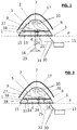
figure 1 représente une vue schématique simplifiée en coupe d'un outil de réparation du radôme selon la présente invention ; - la
figure 2 représente une vue schématique simplifiée en coupe d'une autre forme de réalisation d'un outil de réparation selon la présente invention ; - les
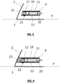
figures 3 et 4 représentent une vue en coupe schématique partielle agrandie et détaillée de la zone entourée en pointillés sur lafigure 1 d'une forme de réalisation du capot de l'outil de réparation selon la présente invention. - Comme le montrent les
figures 1 et 2 , la présente invention se rapporte à un procédé de réparation d'un radôme 1 et plus particulièrement dans l'exemple décrit ci-dessous d'un radôme d'aéronef. - Le radôme 1 comprend un panneau 2 en matériau perméable aux ondes électromagnétiques et par exemple en matériau composite. Le panneau 2 présente une double courbure de manière à former une concavité en forme de dôme. Le bord 3 périphérique libre du radôme 1 est joint, en général de manière articulé, par tout type de moyen connu au reste du fuselage de l'aéronef. Dans la description qui suit, on considère que le radôme a été démonté et retiré de l'aéronef comme montré sur les
figures 1 et 2 . Le panneau 2 présente une face 4 interne et une face 5 externe. La face 4 interne du panneau est creuse. Dans les formes illustrées sur lesfigures 1 et 2 , le bord 3 périphérique libre ou au moins une partie du bord appartient à un plan P : de ce fait, le radôme peut reposer contre une surface plane et en particulier sur le sol par son bord 3 périphérique ou la partie appartenant au plan P de celui-ci, la partie en question du bord 3 étant de dimension suffisamment importante pour ce faire. - Le radôme 1 ne sera pas décrit plus en détail : il peut comprendre d'autres composants tels que des bandes parafoudre ou autres dont la description n'est pas nécessaire pour présenter le procédé et l'outil de réparation.
- Le panneau 2 du fait de son exposition à l'extrémité avant de l'aéronef subit des endommagements qu'il convient de réparer.
- Le procédé de réparation comprend plusieurs étapes dont la première consiste à reconstruire le panneau 2 du radôme 1 sur une zone 7 endommagée. Pour ce faire, une découpe selon un mode opératoire de type connu est pratiquée pour retirer la zone 7 endommagée et des éléments de remplacement viennent combler la découpe opérée. De manière connue, et selon un exemple illustratif, le panneau 2 composite résulte de la superposition d'un certain nombre de plis du côté de la face 4 interne, d'une couche de nid d'abeille puis d'un certain nombre de plis du côté de la face 5 externe. Selon un exemple de mode opératoire, toujours à titre illustratif, les plis du panneau 2 sont découpés, les découpes étant de taille décroissante de la face 4 interne à la face 5 externe. La couche de nid d'abeille est également découpée selon le même contour que le pli le plus proche de ladite couche se trouvant du côté de la face 5 externe Les plis et la couche de nid d'abeille sont ensuite reconstitués : une première pièce composite de réparation dont la forme du contour est identique à celle du contour de la découpe du pli se trouvant sur la face 5 externe et de dimension très légèrement inférieure est inséré à l'intérieur de la dite découpe. Une deuxième pièce de dimension supérieure à la précédente pièce dont la forme du contour est identique à la forme du contour de la découpe du pli le plus proche du précédent et de dimension très légèrement inférieure est inséré à l'intérieur de la découpe de ce deuxième pli et ainsi de suite jusqu'à la couche de nid d'abeille. Une portion de nid d'abeille de réparation est insérée à l'intérieur de la découpe de la couche de nid d'abeille : une couche de colle est prévue sur la face inférieure et supérieure de la couche de nid d'abeille pour la liaison avec les plis les plus proches. On reprend ensuite l'insertion de pièces dans les découpes des plis jusqu'à la face 4 interne.
- Une fois la zone 7 reconstruite, le procédé comprend une étape de chauffage du radôme et plus particulièrement de la zone 7 endommagée pour assurer la cuisson permettant la fixation des pièces de réparation et portion de nid d'abeille de réparation au panneau 2 de radôme découpé.
- Le procédé de réparation utilise la concavité du radôme 1 pour en faire une enceinte de chauffage. Ainsi on ferme un espace intérieur du dôme formé par le panneau 2 de radôme par un capot 8 isolant pour former une enceinte 9, appelée enceinte de réparation. La surface du panneau 2 formant ladite enceinte 9 de réparation contient la zone 7 endommagée à réparer et ne contient pas le bord 3 périphérique libre. Selon la forme illustrée, le capot 8 isolant est formé d'un seul bloc ce qui facilite son déplacement et sa mise en place à l'intérieur du radôme. Le contour du capot 8 présente une forme correspondante à celle du contour intérieur du radome sur lequel il s'applique. Ainsi il suffit de saisir le capot, de le déplacer pour l'introduire à l'intérieur du radome contre la face 4 interne duquel il vient s'appliquer pour former l'enceinte de chauffage.
- Une fois l'enceinte 9 de réparation fermée par le capot 8, on procède au chauffage de l'espace intérieur à ladite enceinte : l'enceinte de réparation devient une enceinte de chauffage. On procède au chauffage à une température de cuisson telle que la surface du panneau 2 faisant partie de l'enceinte de réparation ne se trouve pas impactée contrairement à la zone 7. La polymérisation d'un panneau en composite s'opère à une température appelée T1 de cuisson. Pour réaliser la réparation, il n'est pas nécessaire d'atteindre la température T1 de cuisson. Il suffit d'atteindre une température T2 inférieure à la température T1 de cuisson et de la maintenir pendant un temps plus long que celui nécessaire pour la cuisson. Ainsi le mode opératoire utilisé pour réparer un panneau dans les enceintes de chauffage de type autoclave ou étuve consiste à chauffer la zone 7 endommagée à une température T2 de réparation inférieure à la température T1 de cuisson et pendant un temps plus long que celui nécessaire pour la polymérisation d'un panneau. Le même mode opératoire est utilisé dans l'enceinte 9 de chauffage. Le panneau 2 dans sa globalité peut ainsi résister à la chaleur pour assurer sa fonction d'enceinte 9 de chauffage.
- De plus, le bord 3 périphérique libre étant extérieur à l'enceinte 9 de chauffage, il n'est pas nécessaire de démonter le cadre 15 métallique ou tous les autres éléments qui se trouvent fixés sur le bord 3 pour assurer l'interface avec le reste du fuselage ou sur la surface du panneau 2 comprise entre le bord périphérique libre et le capot. Le procédé permet ainsi d'utiliser le radôme proprement dit comme enceinte de chauffage.
- L'étape de chauffage peut comprendre la détection d'au moins une température à l'intérieur de l'enceinte 9 de chauffage pour contrôler le chauffage de ladite enceinte à la température T2 de réparation. Au moins un capteur 10 de mesure de température est installé sur la face 4 interne du panneau 2 appartenant à l'enceinte 9 ou du capot 8 et transmet la (ou les) température(s) détectée(s) à un centre 11 de commande extérieur à l'enceinte 9 de chauffage. Un opérateur peut ainsi visualiser la température atteinte en différents endroits de l'enceinte 9 de chauffage, en vérifier la valeur et l'homogénéité si plusieurs températures ont été mesurées et réguler le chauffage si nécessaire. Cette régulation peut également être réalisée automatiquement. L'utilisation de plusieurs capteurs 10 permet de vérifier l'homogénéité de la température dans l'enceinte 9. Elle a aussi pour fonction d'assurer la mesure en cas de panne d'un des capteurs ou de déceler la défaillance d'un capteur au travers de mesures fausses isolées. Les capteurs sont disposés à proximité de la zone 7 endommagée. En effet, il est nécessaire d'atteindre la température T2 de réparation au niveau de la zone 7 mais pas indispensable partout ailleurs dans l'enceinte 9.
- Le procédé peut comprendre une étape de brassage de l'air contenu dans l'enceinte 9 de réparation. Selon une forme de réalisation particulière, le brassage de l'air s'enclenche avec le démarrage du chauffage mais il peut démarrer avant ou après le début du chauffage. Le brassage de l'air a pour but d'homogénéiser la répartition de l'air chaud dans l'enceinte de chauffage pour assurer les mêmes conditions de polymérisation sur toute la surface de la zone 7 endommagée.
- Le procédé peut comprendre une étape de déploiement d'un joint 12 déployable entre le capot 8 et le panneau 2 permettant la fermeture hermétique de ladite enceinte 9 de réparation. Une fois le capot en place, le déploiement du joint 12 est activé par soufflage, gonflage, actionnement mécanique ou tout autre type d'action le permettant. Le déploiement du joint permet d'assurer l'isolation de la jointure entre le capot 8 et le panneau 2. Dans la forme de réalisation illustrée sur les
figures 4 et 5, le bord périphérique du capot 8 est pourvu du joint 12. Le joint 12 se déploie par déformation et plus précisément dans la forme de réalisation illustrée par gonflage. Le joint se déploie vers l'extérieur du capot 8 soit dans la direction du panneau 2 une fois le capot installé. Le joint s'applique sur le panneau 2 et assure une fermeture hermétique de l'enceinte 9 de chauffage. Une fois la réparation réalisée, il est possible de réinsérer le joint dans le capot manuellement ou par aspiration. - Dans le cas d'un capot 8 dont les dimensions ne sont pas en adaptées à celles du radôme 1 pour permettre la formation d'une enceinte contenant la zone 7 endommagée, l'utilisation d'un joint 12 déployable peut permettre l'adaptation du capot aux diverses formes ou dimensions de panneaux 2 de radôme. Le capot 8 n'a donc pas besoin de présenter des dimensions en parfaite correspondance avec celle du panneau 2. Grâce à l'utilisation d'un joint 12 déployable, il convient à plusieurs types, formes, tailles de radôme.
- Le procédé présente une étape de maintien du capot en place pour former une enceinte 9 de chauffage. Cette étape peut être combinée à l'étape précédente de fermeture hermétique de l'enceinte : en effet, le joint peut présenter une fonction d'adhérence telle qu'il maintient le capot en place.
- L'étape de maintien peut également précéder ou suivre l'étape de déploiement du joint. Le maintien du capot en place peut être réalisé de diverses manières.
- Selon une forme de réalisation possible, le procédé consiste à utiliser des systèmes amovibles de fixation de type scotch, « VELCRO » (marque déposée), vis/écrou ou autre. Ces systèmes joignent la face 13 externe du bord périphérique libre du capot à la face interne 4 du panneau.
- Selon une forme de réalisation particulière illustrée sur la
figure 2 , le procédé consiste en la mise en place d'un système amovible de fixation sous la forme d'au moins une cale 14 longiligne dont une extrémité prend appui sur la face 13 externe du capot et dont l'autre extrémité prend appui sur une structure fixe pour permettre le maintien du capot. La structure fixe peut être de toute nature le sol, un mur, une plate-forme voire même le radôme lui-même. - Selon la forme de réalisation illustrée, la structure fixe consiste en la structure du radôme proprement dit. Le procédé peut donc être réalisé n'importe où, sur n'importe quelle surface. La cale prend appui par exemple sur le cadre 15 métallique fixé au niveau du bord 3 périphérique libre du panneau 2 pour maintenir par son autre extrémité le capot auquel il est fixé. Le nombre de cales est déterminé suivant les besoins, les cales étant réparties de manière équilibrée sur la surface du capot.
- Les systèmes amovibles de fixation peuvent se combiner ; on peut utiliser par exemple du scotch pour assurer un premier maintien renforcé par l'ajout de cales.
- Un accès en dessous du dôme du panneau 2 facilite la mise en oeuvre du procédé de réparation. Le dôme peut donc au lieu de reposer sur une surface être suspendu ou fixé de manière à laisser un accès libre à l'enceinte de chauffage. Le procédé comprend une étape de mise en place de moyens 16 de soutien du panneau 2 pour faciliter l'accès à l'enceinte 9 de chauffage.
- Selon la forme de réalisation représentée sur la
figure 1 , le panneau 2 est maintenu en hauteur à l'aide d'un support 16. De cette manière l'outil est posé au sol au moyen du support 16 et il suffit d'approcher le radôme et de le poser sur l'outil. Dans la forme de réalisation illustrée sur lafigure 1 , le support se présente sous la forme d'un pied unique central évasé à son extrémité basse pour prendre appui de manière stable sur la surface sur laquelle il repose. Le pied et la base évasée peuvent présenter des formes variées comme il sera décrit plus loin. Le pied est ici unique mais à l'image d'une table, le support peut comprendre plus d'un pied ou se présenter sous tout autre type de forme. - Le procédé peut présenter une étape de mise en place d'une couverture 17 isolante thermiquement pour recouvrir la face 5 externe du panneau 2 de radôme. La couverture 17 isolante accélère la montée en température et renforce l'isolation thermique de l'enceinte 9 de chauffage.
- Le procédé de réparation offre ainsi les avantages d'éviter le recours à des moyens lourds tels qu'autoclave ou étuve, d'avoir à démonter des composants du radôme tels que le cadre 15 se trouvant au niveau du bord périphérique libre du panneau 2, de transporter le radôme sur de longues distances. Le procédé peut être opéré rapidement, simplement et en tout lieu. Il peut s'appliquer à tous les types de radôme.
- Le procédé de réparation nécessite l'utilisation d'un outil présenté dans ces grands principes avec la description précédente du procédé et de manière plus détaillée dans ce qui suit.
- Dans la forme de réalisation illustrée sur les
figures 1 et 2 , l'outil comprend le capot 8 permettant de refermer le panneau 2 du radôme. Le capot 8 présente donc une forme en correspondance avec celle du panneau 2 et plus précisément du dôme formé par la face 4 interne du panneau 2. Si le panneau 2 est hémi sphérique, le capot 8 se présente sous la forme d'un disque. Le capot comporte un orifice 18 pratiqué par exemple au centre de sa surface, à savoir pour un disque au centre du disque. L'orifice 18 peut être prévu ailleurs qu'au centre du capot (figures 1 et 2 ). - Selon les formes illustrées sur les
figures 1 et 2 , le capot 8 présente une surface plane dont le bord 3 périphérique libre vient en contact avec la face 4 interne du panneau 2. Dans la forme de réalisation illustrée sur lesfigures 3 et 4 , le capot comprend deux panneaux, un panneau 19 supérieur et un panneau 20 inférieur en matériau composite. Les deux panneaux sont séparés par une couche de mousse 21 isolante thermiquement. - Il est possible de prévoir un capot ne présentant aucune surface plane. On pourrait par exemple prévoir une surface courbe permettant de diminuer le volume de l'enceinte de chauffage. Cependant comme montré sur les
figures 1 et 2 , la surface plane est dans de nombreux cas de configuration la surface la plus optimisée pour faciliter l'installation. - Comme le montrent les
figures 3 et 4 , et comme vu précédemment, le bord périphérique du capot est pourvu du joint 12 déployable. Le joint 12 peut être déployé par déformation, rétraction mécanique de type coulissement ou autre. Dans la forme de réalisation illustrée, le déploiement se fait par déformation et plus précisément par gonflage. Le joint 12 se présente sous la forme d'une chambre à air logée à l'intérieur du bord périphérique du capot sur tout le périmètre. Une entrée 22 d'air est prévue dans la chambre à air dont l'accès est réalisé par une valve 23 accessible depuis la face 13 externe du capot. En réalisant un gonflage au niveau de ladite valve 23, la chambre à air se remplit d'air et se déforme. Les bords périphériques extérieurs du panneau 20 inférieur et du panneau 19 supérieur ne sont pas joints de manière à laisser l'accès libre à l'expansion de la chambre à air hors du capot, vers l'extérieur de celui-ci. Selon une forme de réalisation illustrative, des brides en « VELCRO » (marque déposée) peuvent être prévues sur le pourtour du capot pour éviter que le joint 12 ne ressorte de son logement pendant son stockage ou son transport. Les brides sont libérées lors de la mise en place du capot. La taille de la chambre à air est telle qu'une fois gonflée, elle vienne en contact et s'appliquer voire se coller par pression à la face interne du panneau 2 pour assurer la fermeture hermétique de l'enceinte de réparation. La forme et la dimension du capot sont déterminés par rapport à la forme et à la taille des radômes sur lesquels il est prévu qu'il s'applique et par rapport à la présence et la forme dudit joint. Il peut également être prévu de réaliser une aspiration par la valve 23 à l'aide d'un dispositif d'aspiration de type connu pour remettre le joint 12 à l'intérieur du capot. - L'outil de réparation comprend des moyens 24 de chauffage permettant de chauffer l'espace intérieur de ladite enceinte 9 de réparation formant l'enceinte de chauffage et permettant la cuisson attendue pour la réparation de la zone 7 endommagée. Comme le montrent les
figures 1 et 2 , les moyens 24 de chauffage se présentent sous la forme d'un dispositif 25 de génération d'air chaud susceptible d'être intégré de manière amovible au capot. Les moyens de chauffage se présentent par exemple sous la forme d'un pistolet 25 à air chaud dont le conduit 26 expulsant l'air chaud est introduit dans l'orifice 18 prévu au centre du capot. Le dispositif 25 de génération d'air chaud est fixé de manière amovible au capot par exemple à l'aide de brides. Tout autre type de fixation peut être utilisé. - L'outil comprend des moyens de brassage d'air. Dans la forme de réalisation illustrée sur la
figure 1 , les moyens de brassage se présentent sous la forme d'un ventilateur 27 électrique. Les moyens de brassage pourrait également se présenter sous la forme d'un déflecteur mécanique. Il peut être disposé et fixé à l'intérieur de l'enceinte 9 par tout type de moyen connu. Dans l'exemple illustré, l'hélice du ventilateur 9 est associée au conduit 26 d'expulsion du dispositif de génération d'air chaud. Ainsi il est au plus près de ce dernier et permet un brassage optimisé. - L'hélice présente une forme telle qu'elle agit également en déflecteur. Le déflecteur peut aussi être indépendant de l'hélice et par exemple se présenter sous la forme d'une tôle perforée placée à distance de la sortie des moyens de chauffage et dans l'exemple décrit du pistolet à air chaud. Le déflecteur permet d'éviter un point chaud au droit du pistolet, de diffuser de manière optimisée et homogénéisée la température dans l'enceinte de chauffage.
- Comme vu précédemment, l'outil de réparation du radôme comprend au moins une cale 14 longiligne dont une extrémité prend appui sur la surface externe du capot et dont l'autre extrémité prend appui sur une structure fixe pour permettre le maintien du capot. Dans les formes de réalisation illustrées sur les
figures 1 et 2 , la structure fixe est le cadre 15 fixé sur le bord 3 périphérique libre du panneau 2. La cale 14 longe la face interne du panneau 2 entre le cadre et la face externe du capot. Les cales sont réparties tout autour de la périphérie du capot. Les cales sont fixées à la face externe du capot à l'aide de tout système de jointure 28 articulé de type connu. - Pour améliorer l'isolation, il est également possible de recouvrir le radôme d'une couverture 17 isolante. Celle-ci doit être de forme telle qu'elle recouvre entièrement la face externe du panneau 2 de radôme ou au moins jusqu'au niveau du capot 8. La couverture 17 est faite d'un matériau isolant de type connu.
- L'outil de réparation peut comprendre des moyens 16 de soutien pour faciliter l'accès à l'enceinte de chauffage. Ces moyens ne sont pas nécessaires. En effet, une fois l'ensemble des composants de l'outil en place, le radôme peut reposer sur le sol ou toute autre surface et le pilotage du chauffage est assuré par l'intermédiaire du centre 11 de commande susceptible d'être extérieur et distant du radôme.
- La
figure 1 illustre une forme de réalisation des moyens de soutien. Les moyens de soutien se présentent sous la forme d'un support 16 de type pied de table. Dans l'exemple, un seul pied 16 est prévu prenant à une extrémité appui sur le sol par l'intermédiaire d'une base 29 de stabilisation et à l'autre extrémité supportant le capot en son centre. Le pied est fixé de manière amovible ou pas au capot. Le pied est par exemple de forme cylindrique, de section circulaire, rectangulaire ou autre. La base 29 est par exemple de forme conique, pyramidale ou autre. Pour faciliter la mise en place des moyens 24 de chauffage et un emplacement central de ces derniers, le support 16 peut présenter plus d'un pied permettant de les répartir autour du centre du capot, laissant le centre libre pour l'installation des moyens de chauffage. - L'outil de réparation peut comprendre des moyens de détection de température prévus à l'intérieur de l'enceinte de réparation, les moyens de détection étant couplés au centre 11 de commande des moyens de chauffage de l'enceinte de réparation. Les moyens de détection se présentent sous la forme de capteurs 10 de mesure tels que des thermocouples. Les moyens de détection comprennent au moins un capteur. Le ou les capteurs 10 sont disposés à l'intérieur de l'enceinte de réparation/chauffage et plus particulièrement comme l'illustre la
figure 1 , sur la face interne du radôme. Dans l'exemple de lafigure 1 , trois capteurs sont représentés. Les capteurs sont reliés au centre de commande extérieur au radôme par une liaison 30 par exemple de type filaire que l'on peut faire passer par l'orifice central, par l'extérieur du capot (entre le capot et le panneau 2 de radôme) ou encore par des orifices complémentaires prévus dans le capot. - Le centre 11 de commande extérieur se présente sous la forme d'une valise de visualisation des données mesurées et de commande des moyens de chauffage et de brassage/déflection de l'air contenu dans l'enceinte de chauffage. Pour ce faire, le centre de commande est également relié par une liaison 31 par exemple de type filaire aux moyens de chauffage et aux moyens de brassage d'air et de déflexion.
Claims (15)
- Procédé de réparation d'un radôme (1) comprenant un panneau (2) présentant une double courbure formant dôme, ledit panneau comportant au moins une zone (7) endommagée caractérisé en ce qu'il comprend les étapes suivantes :- fermeture d'un espace intérieur du panneau (2) par un capot (8) pour former une enceinte (9), appelée enceinte de réparation, la surface du panneau (2) formant ladite enceinte (9) de réparation contenant ladite zone (7) endommagée ;- chauffage de l'espace intérieur à ladite enceinte (9) de réparation formant ainsi une enceinte de chauffage permettant la cuisson attendue pour la réparation de la zone endommagée.
- Procédé de réparation d'un radôme selon la revendication 1, caractérisé en ce qu'il comprend une étape de préparation de ladite zone (7) endommagée par découpe et insertion d'éléments de remplacement dans les découpes opérées nécessitant une cuisson pour la fixation desdits éléments au panneau (2).
- Procédé de réparation d'un radôme selon l'une des revendications 1 ou 2, caractérisé en ce que l'étape de chauffage comprend la détection d'au moins une température à l'intérieur de l'enceinte (9) de chauffage pour contrôler le chauffage de ladite enceinte de manière à atteindre une température T2 de réparation inférieure à une température T1 de cuisson du panneau.
- Procédé de réparation d'un radôme selon l'une des revendications 1 à 3, caractérisé en ce qu'il comprend une étape de brassage de l'air contenu dans ladite enceinte (9).
- Procédé de réparation d'un radôme selon l'une des revendications 1 à 4, caractérisé en ce qu'il comprend une étape de déploiement d'un joint (12) déployable entre le capot (8) et le panneau (2) permettant la fermeture hermétique de ladite enceinte (9) de réparation.
- Procédé de réparation d'un radôme selon l'une des revendications 1 à 5, caractérisé en ce qu'il comprend une étape de maintien du capot (8) par la mise en place d'au moins une cale (14) longiligne dont une extrémité prend appui sur la face (13) externe du capot et dont l'autre extrémité prend appui sur une structure fixe.
- Procédé de réparation d'un radôme selon l'une des revendications 1 à 6, caractérisé en ce qu'il comprend une étape de mise en place de moyens (16) de soutien du panneau (2) pour faciliter l'accès à l'enceinte (9) de chauffage.
- Procédé de réparation d'un radôme selon l'une des revendications 1 à 7, caractérisé en ce qu'il comprend une étape de mise en place d'une couverture (17) isolante sur au moins une partie de la face externe (5) du panneau (2) de radôme.
- Outil de réparation d'un radôme (1) comprenant un panneau (2) présentant une double courbure formant dôme, ledit panneau (2) présentant au moins une zone (7) endommagée caractérisé en ce que l'outil comprend le panneau (2) proprement dit, un capot (8) permettant de fermer un espace intérieur du panneau (2) de radôme pour former une enceinte (9), appelée enceinte de réparation, la surface du panneau (2) de radôme formant ladite enceinte de réparation contenant ladite zone (7) endommagée et des moyens (24) de chauffage permettant de chauffer l'espace intérieur de ladite enceinte (9) de réparation formant ainsi une enceinte de chauffage permettant la cuisson attendue pour la réparation de la zone endommagée.
- Outil de réparation d'un radôme selon la revendication 9, caractérisé en ce que le capot (8) est formé d'un seul bloc et présente une forme dont le contour correspond au contour intérieur du panneau contre lequel il doit s'appliquer, le bord (3) périphérique libre étant extérieur à l'enceinte (9) de chauffage.
- Outil de réparation d'un radôme selon l'une des revendication 9 ou 10, caractérisé en ce que les moyens de chauffage se présentent sous la forme d'un dispositif (25) de génération d'air chaud susceptible d'être intégré de manière amovible au capot et de le traverser par un orifice (18) prévu à cet effet.
- Outil de réparation d'un radôme selon l'une des revendications 9 à 11, caractérisé en ce qu'il comprend des moyens (27) de brassage d'air.
- Outil de réparation d'un radôme selon l'une des revendications 9 à 12, caractérisé en ce que le bord périphérique libre du capot (8) comprend un joint (12) déployable.
- Outil de réparation d'un radôme selon l'une des revendications 9 à 13, caractérisé en ce que des moyens (10) de détection de température sont prévus à l'intérieur de l'enceinte de réparation, les moyens de détection étant couplés à un centre (11) de commande des moyens (24) de chauffage de l'enceinte de réparation.
- Outil de réparation d'un radôme selon l'une des revendications 9 à 14, caractérisé en ce qu'il comprend au moins une cale (14) longiligne dont une extrémité prend appui sur la face (13) externe du capot et dont l'autre extrémité prend appui sur une structure fixe.
Applications Claiming Priority (1)
| Application Number | Priority Date | Filing Date | Title |
|---|---|---|---|
| FR1655700A FR3052749B1 (fr) | 2016-06-20 | 2016-06-20 | Procede de reparation de radome |
Publications (2)
| Publication Number | Publication Date |
|---|---|
| EP3260284A1 true EP3260284A1 (fr) | 2017-12-27 |
| EP3260284B1 EP3260284B1 (fr) | 2022-02-16 |
Family
ID=56611462
Family Applications (1)
| Application Number | Title | Priority Date | Filing Date |
|---|---|---|---|
| EP17173197.9A Active EP3260284B1 (fr) | 2016-06-20 | 2017-05-29 | Procede de reparation d'un radome utilisant le radome comme enceinte de chauffage et outil pour sa mise en oeuvre |
Country Status (4)
| Country | Link |
|---|---|
| US (1) | US10414097B2 (fr) |
| EP (1) | EP3260284B1 (fr) |
| CN (1) | CN107521132B (fr) |
| FR (1) | FR3052749B1 (fr) |
Families Citing this family (3)
| Publication number | Priority date | Publication date | Assignee | Title |
|---|---|---|---|---|
| CN109334055B (zh) * | 2018-10-30 | 2020-10-30 | 宁夏大学 | 一种用于复合材料制件修复的在位加工装置 |
| CN109353037A (zh) * | 2018-11-26 | 2019-02-19 | 华南理工大学 | 一种热塑性塑料汽车零部件快速维修装置与方法 |
| CN111844819A (zh) * | 2020-07-29 | 2020-10-30 | 北京石头世纪科技股份有限公司 | 一种pc料表面损伤热风整平修复方法 |
Citations (5)
| Publication number | Priority date | Publication date | Assignee | Title |
|---|---|---|---|---|
| US4808253A (en) * | 1987-11-06 | 1989-02-28 | Grumman Aerospace Corporation | Method and apparatus for performing a repair on a contoured section of a composite structure |
| FR2693147A1 (fr) * | 1992-07-02 | 1994-01-07 | Leobon Laurent | Procédé et installation pour la réparation de pièces en matériau composite, notamment de type sandwich. |
| FR2953812A1 (fr) | 2009-12-11 | 2011-06-17 | Airbus Operations Sas | Procede de reparation d'un fuselage d'aeronef |
| EP2371523A1 (fr) * | 2010-03-29 | 2011-10-05 | Alenia Aeronautica S.P.A. | Procédé et dispositif pour réparer des pièces en matériau composite d'un avion |
| EP2881246A1 (fr) * | 2013-12-04 | 2015-06-10 | Airbus Operations GmbH | Procédé et appareil de réparation de composants composites |
Family Cites Families (7)
| Publication number | Priority date | Publication date | Assignee | Title |
|---|---|---|---|---|
| US4668317A (en) * | 1984-06-01 | 1987-05-26 | The United States Of America As Represented By The Secretary Of The Air Force | Damaged radar radome repair method |
| US6270603B1 (en) * | 1991-04-09 | 2001-08-07 | The Boeing Company | Repair method for uniformly heating composite structure |
| FR2891193B1 (fr) * | 2005-09-29 | 2007-10-26 | Airbus France Sas | Procede de reparation traversante de structure composite a trois peaux et deux couches d'ame |
| US8091229B2 (en) * | 2011-03-08 | 2012-01-10 | General Electric Company | Method of repairing a subsurface void or damage for a wind turbine blade |
| US8844108B2 (en) * | 2011-07-12 | 2014-09-30 | The Boeing Company | Large area repair of composite aircraft |
| US9216806B2 (en) * | 2011-11-23 | 2015-12-22 | Stratospheric Airships, Llc | Durable airship hull and in situ airship hull repair |
| DK2986441T3 (da) * | 2013-04-17 | 2025-09-01 | Lm Wind Power As | Fremgangsmåde og system til reparation af en vindmøllevinge |
-
2016
- 2016-06-20 FR FR1655700A patent/FR3052749B1/fr not_active Expired - Fee Related
-
2017
- 2017-05-29 EP EP17173197.9A patent/EP3260284B1/fr active Active
- 2017-06-14 US US15/622,820 patent/US10414097B2/en active Active
- 2017-06-19 CN CN201710462128.3A patent/CN107521132B/zh active Active
Patent Citations (5)
| Publication number | Priority date | Publication date | Assignee | Title |
|---|---|---|---|---|
| US4808253A (en) * | 1987-11-06 | 1989-02-28 | Grumman Aerospace Corporation | Method and apparatus for performing a repair on a contoured section of a composite structure |
| FR2693147A1 (fr) * | 1992-07-02 | 1994-01-07 | Leobon Laurent | Procédé et installation pour la réparation de pièces en matériau composite, notamment de type sandwich. |
| FR2953812A1 (fr) | 2009-12-11 | 2011-06-17 | Airbus Operations Sas | Procede de reparation d'un fuselage d'aeronef |
| EP2371523A1 (fr) * | 2010-03-29 | 2011-10-05 | Alenia Aeronautica S.P.A. | Procédé et dispositif pour réparer des pièces en matériau composite d'un avion |
| EP2881246A1 (fr) * | 2013-12-04 | 2015-06-10 | Airbus Operations GmbH | Procédé et appareil de réparation de composants composites |
Also Published As
| Publication number | Publication date |
|---|---|
| CN107521132A (zh) | 2017-12-29 |
| FR3052749A1 (fr) | 2017-12-22 |
| US20170361537A1 (en) | 2017-12-21 |
| EP3260284B1 (fr) | 2022-02-16 |
| US10414097B2 (en) | 2019-09-17 |
| FR3052749B1 (fr) | 2019-07-05 |
| CN107521132B (zh) | 2021-09-14 |
Similar Documents
| Publication | Publication Date | Title |
|---|---|---|
| EP3260284B1 (fr) | Procede de reparation d'un radome utilisant le radome comme enceinte de chauffage et outil pour sa mise en oeuvre | |
| EP1471212B1 (fr) | Procédé pour remplacer un abradable sur le carter de soufflante d'un turboréacteur | |
| EP1251257B1 (fr) | Capot d'entrée d'air pour moteur à réaction, pourvu de moyens de dégivrage | |
| EP2683449B1 (fr) | Dispositif d'extinction d'incendie declenche | |
| FR2999650A1 (fr) | Panneaux acoustiques amovibles pour carter de turboreacteur. | |
| EP0918149B1 (fr) | Dispositif de protection pour capot d'entrée d'air de moteur à réaction, pourvu d'un système de dégivrage | |
| FR2941031A1 (fr) | Obturateur etanche d'une ouverture d'une tubulure de jonction d'une enceinte et d'une canalisation et procede pour la mise en oeuvre d'un tel obturateur | |
| CA2702009A1 (fr) | Cale en materiau composite renforcee et procede de renforcement d'une cale en materiau composite | |
| WO2010119227A1 (fr) | Dispositif de fixation d'un plenum a une soufflerie | |
| EP2594391B1 (fr) | Appareil de chauffage localisé d'une surface à réparer en matériau polymère, par ventilation d'un fluide chaud à l'intérieur d'une chambre de confinement | |
| FR3072908A1 (fr) | Ensemble propulsif pour aeronef | |
| CA2908099C (fr) | Dispositif de camouflage thermique et vehicule comportant un tel dispositif. | |
| EP3145694B1 (fr) | Procédé et machine de collage d'un revêtement souple sur un support utilisant des ondes électromagnétiques | |
| FR3120352A1 (fr) | Entree d’air de nacelle munie d’un système de protection contre la glace mixte | |
| FR2789868A1 (fr) | Bouilloire electrique a plaque metallique chauffante | |
| EP4162576B1 (fr) | Dispositif de confinement d'une fuite de gaz au niveau de l'interface entre un cone isolant ou un joint plat et une bride | |
| FR2920957A3 (fr) | Appareil de boulangerie | |
| EP4235011B1 (fr) | Réservoir intégrant un support d'équipements auquel sont reliés différents équipements et procédé de fabrication dudit réservoir | |
| FR2867260A1 (fr) | Dispositif pour raccorder un element radiant chauffe au gaz | |
| CA3176764C (fr) | Dispositif de confinement d'une fuite de gaz au niveau de l'interface entre un cone isolant ou un joint plat et une bride | |
| EP3794958B1 (fr) | Cuve a capot | |
| EP3890568B1 (fr) | Accessoire cuiseur vapeur avec dispositif de support revetu en silicone | |
| FR2981100A1 (fr) | Toiture pour abri leger, abri leger equipe d'une telle toiture et procede d'installation d'une telle toiture | |
| EP4132848A1 (fr) | Organe d'obturation amovible pour une partie femelle logee dans une ouverture exterieure d'une nacelle de moteur d'aeronef | |
| FR3082551A1 (fr) | Systeme de propulsion d'un aeronef comportant une structure interieure fixe presentant une fente d'evacuation |
Legal Events
| Date | Code | Title | Description |
|---|---|---|---|
| PUAI | Public reference made under article 153(3) epc to a published international application that has entered the european phase |
Free format text: ORIGINAL CODE: 0009012 |
|
| STAA | Information on the status of an ep patent application or granted ep patent |
Free format text: STATUS: THE APPLICATION HAS BEEN PUBLISHED |
|
| AK | Designated contracting states |
Kind code of ref document: A1 Designated state(s): AL AT BE BG CH CY CZ DE DK EE ES FI FR GB GR HR HU IE IS IT LI LT LU LV MC MK MT NL NO PL PT RO RS SE SI SK SM TR |
|
| AX | Request for extension of the european patent |
Extension state: BA ME |
|
| STAA | Information on the status of an ep patent application or granted ep patent |
Free format text: STATUS: REQUEST FOR EXAMINATION WAS MADE |
|
| 17P | Request for examination filed |
Effective date: 20180627 |
|
| RBV | Designated contracting states (corrected) |
Designated state(s): AL AT BE BG CH CY CZ DE DK EE ES FI FR GB GR HR HU IE IS IT LI LT LU LV MC MK MT NL NO PL PT RO RS SE SI SK SM TR |
|
| GRAP | Despatch of communication of intention to grant a patent |
Free format text: ORIGINAL CODE: EPIDOSNIGR1 |
|
| STAA | Information on the status of an ep patent application or granted ep patent |
Free format text: STATUS: GRANT OF PATENT IS INTENDED |
|
| INTG | Intention to grant announced |
Effective date: 20210701 |
|
| GRAJ | Information related to disapproval of communication of intention to grant by the applicant or resumption of examination proceedings by the epo deleted |
Free format text: ORIGINAL CODE: EPIDOSDIGR1 |
|
| STAA | Information on the status of an ep patent application or granted ep patent |
Free format text: STATUS: REQUEST FOR EXAMINATION WAS MADE |
|
| INTC | Intention to grant announced (deleted) | ||
| GRAP | Despatch of communication of intention to grant a patent |
Free format text: ORIGINAL CODE: EPIDOSNIGR1 |
|
| STAA | Information on the status of an ep patent application or granted ep patent |
Free format text: STATUS: GRANT OF PATENT IS INTENDED |
|
| GRAJ | Information related to disapproval of communication of intention to grant by the applicant or resumption of examination proceedings by the epo deleted |
Free format text: ORIGINAL CODE: EPIDOSDIGR1 |
|
| GRAP | Despatch of communication of intention to grant a patent |
Free format text: ORIGINAL CODE: EPIDOSNIGR1 |
|
| INTG | Intention to grant announced |
Effective date: 20211013 |
|
| INTG | Intention to grant announced |
Effective date: 20211026 |
|
| GRAS | Grant fee paid |
Free format text: ORIGINAL CODE: EPIDOSNIGR3 |
|
| GRAA | (expected) grant |
Free format text: ORIGINAL CODE: 0009210 |
|
| STAA | Information on the status of an ep patent application or granted ep patent |
Free format text: STATUS: THE PATENT HAS BEEN GRANTED |
|
| AK | Designated contracting states |
Kind code of ref document: B1 Designated state(s): AL AT BE BG CH CY CZ DE DK EE ES FI FR GB GR HR HU IE IS IT LI LT LU LV MC MK MT NL NO PL PT RO RS SE SI SK SM TR |
|
| REG | Reference to a national code |
Ref country code: GB Ref legal event code: FG4D Free format text: NOT ENGLISH |
|
| REG | Reference to a national code |
Ref country code: CH Ref legal event code: EP |
|
| REG | Reference to a national code |
Ref country code: DE Ref legal event code: R096 Ref document number: 602017053363 Country of ref document: DE |
|
| REG | Reference to a national code |
Ref country code: AT Ref legal event code: REF Ref document number: 1468639 Country of ref document: AT Kind code of ref document: T Effective date: 20220315 |
|
| REG | Reference to a national code |
Ref country code: IE Ref legal event code: FG4D Free format text: LANGUAGE OF EP DOCUMENT: FRENCH |
|
| REG | Reference to a national code |
Ref country code: LT Ref legal event code: MG9D |
|
| REG | Reference to a national code |
Ref country code: NL Ref legal event code: MP Effective date: 20220216 |
|
| REG | Reference to a national code |
Ref country code: AT Ref legal event code: MK05 Ref document number: 1468639 Country of ref document: AT Kind code of ref document: T Effective date: 20220216 |
|
| PG25 | Lapsed in a contracting state [announced via postgrant information from national office to epo] |
Ref country code: SE Free format text: LAPSE BECAUSE OF FAILURE TO SUBMIT A TRANSLATION OF THE DESCRIPTION OR TO PAY THE FEE WITHIN THE PRESCRIBED TIME-LIMIT Effective date: 20220216 Ref country code: RS Free format text: LAPSE BECAUSE OF FAILURE TO SUBMIT A TRANSLATION OF THE DESCRIPTION OR TO PAY THE FEE WITHIN THE PRESCRIBED TIME-LIMIT Effective date: 20220216 Ref country code: PT Free format text: LAPSE BECAUSE OF FAILURE TO SUBMIT A TRANSLATION OF THE DESCRIPTION OR TO PAY THE FEE WITHIN THE PRESCRIBED TIME-LIMIT Effective date: 20220616 Ref country code: NO Free format text: LAPSE BECAUSE OF FAILURE TO SUBMIT A TRANSLATION OF THE DESCRIPTION OR TO PAY THE FEE WITHIN THE PRESCRIBED TIME-LIMIT Effective date: 20220516 Ref country code: NL Free format text: LAPSE BECAUSE OF FAILURE TO SUBMIT A TRANSLATION OF THE DESCRIPTION OR TO PAY THE FEE WITHIN THE PRESCRIBED TIME-LIMIT Effective date: 20220216 Ref country code: LT Free format text: LAPSE BECAUSE OF FAILURE TO SUBMIT A TRANSLATION OF THE DESCRIPTION OR TO PAY THE FEE WITHIN THE PRESCRIBED TIME-LIMIT Effective date: 20220216 Ref country code: HR Free format text: LAPSE BECAUSE OF FAILURE TO SUBMIT A TRANSLATION OF THE DESCRIPTION OR TO PAY THE FEE WITHIN THE PRESCRIBED TIME-LIMIT Effective date: 20220216 Ref country code: ES Free format text: LAPSE BECAUSE OF FAILURE TO SUBMIT A TRANSLATION OF THE DESCRIPTION OR TO PAY THE FEE WITHIN THE PRESCRIBED TIME-LIMIT Effective date: 20220216 Ref country code: BG Free format text: LAPSE BECAUSE OF FAILURE TO SUBMIT A TRANSLATION OF THE DESCRIPTION OR TO PAY THE FEE WITHIN THE PRESCRIBED TIME-LIMIT Effective date: 20220516 |
|
| PG25 | Lapsed in a contracting state [announced via postgrant information from national office to epo] |
Ref country code: PL Free format text: LAPSE BECAUSE OF FAILURE TO SUBMIT A TRANSLATION OF THE DESCRIPTION OR TO PAY THE FEE WITHIN THE PRESCRIBED TIME-LIMIT Effective date: 20220216 Ref country code: LV Free format text: LAPSE BECAUSE OF FAILURE TO SUBMIT A TRANSLATION OF THE DESCRIPTION OR TO PAY THE FEE WITHIN THE PRESCRIBED TIME-LIMIT Effective date: 20220216 Ref country code: GR Free format text: LAPSE BECAUSE OF FAILURE TO SUBMIT A TRANSLATION OF THE DESCRIPTION OR TO PAY THE FEE WITHIN THE PRESCRIBED TIME-LIMIT Effective date: 20220517 Ref country code: FI Free format text: LAPSE BECAUSE OF FAILURE TO SUBMIT A TRANSLATION OF THE DESCRIPTION OR TO PAY THE FEE WITHIN THE PRESCRIBED TIME-LIMIT Effective date: 20220216 Ref country code: AT Free format text: LAPSE BECAUSE OF FAILURE TO SUBMIT A TRANSLATION OF THE DESCRIPTION OR TO PAY THE FEE WITHIN THE PRESCRIBED TIME-LIMIT Effective date: 20220216 |
|
| PG25 | Lapsed in a contracting state [announced via postgrant information from national office to epo] |
Ref country code: IS Free format text: LAPSE BECAUSE OF FAILURE TO SUBMIT A TRANSLATION OF THE DESCRIPTION OR TO PAY THE FEE WITHIN THE PRESCRIBED TIME-LIMIT Effective date: 20220617 |
|
| PG25 | Lapsed in a contracting state [announced via postgrant information from national office to epo] |
Ref country code: SM Free format text: LAPSE BECAUSE OF FAILURE TO SUBMIT A TRANSLATION OF THE DESCRIPTION OR TO PAY THE FEE WITHIN THE PRESCRIBED TIME-LIMIT Effective date: 20220216 Ref country code: SK Free format text: LAPSE BECAUSE OF FAILURE TO SUBMIT A TRANSLATION OF THE DESCRIPTION OR TO PAY THE FEE WITHIN THE PRESCRIBED TIME-LIMIT Effective date: 20220216 Ref country code: RO Free format text: LAPSE BECAUSE OF FAILURE TO SUBMIT A TRANSLATION OF THE DESCRIPTION OR TO PAY THE FEE WITHIN THE PRESCRIBED TIME-LIMIT Effective date: 20220216 Ref country code: EE Free format text: LAPSE BECAUSE OF FAILURE TO SUBMIT A TRANSLATION OF THE DESCRIPTION OR TO PAY THE FEE WITHIN THE PRESCRIBED TIME-LIMIT Effective date: 20220216 Ref country code: DK Free format text: LAPSE BECAUSE OF FAILURE TO SUBMIT A TRANSLATION OF THE DESCRIPTION OR TO PAY THE FEE WITHIN THE PRESCRIBED TIME-LIMIT Effective date: 20220216 Ref country code: CZ Free format text: LAPSE BECAUSE OF FAILURE TO SUBMIT A TRANSLATION OF THE DESCRIPTION OR TO PAY THE FEE WITHIN THE PRESCRIBED TIME-LIMIT Effective date: 20220216 |
|
| REG | Reference to a national code |
Ref country code: DE Ref legal event code: R097 Ref document number: 602017053363 Country of ref document: DE |
|
| PG25 | Lapsed in a contracting state [announced via postgrant information from national office to epo] |
Ref country code: AL Free format text: LAPSE BECAUSE OF FAILURE TO SUBMIT A TRANSLATION OF THE DESCRIPTION OR TO PAY THE FEE WITHIN THE PRESCRIBED TIME-LIMIT Effective date: 20220216 |
|
| PLBE | No opposition filed within time limit |
Free format text: ORIGINAL CODE: 0009261 |
|
| STAA | Information on the status of an ep patent application or granted ep patent |
Free format text: STATUS: NO OPPOSITION FILED WITHIN TIME LIMIT |
|
| REG | Reference to a national code |
Ref country code: CH Ref legal event code: PL |
|
| REG | Reference to a national code |
Ref country code: BE Ref legal event code: MM Effective date: 20220531 |
|
| 26N | No opposition filed |
Effective date: 20221117 |
|
| PG25 | Lapsed in a contracting state [announced via postgrant information from national office to epo] |
Ref country code: MC Free format text: LAPSE BECAUSE OF FAILURE TO SUBMIT A TRANSLATION OF THE DESCRIPTION OR TO PAY THE FEE WITHIN THE PRESCRIBED TIME-LIMIT Effective date: 20220216 Ref country code: LU Free format text: LAPSE BECAUSE OF NON-PAYMENT OF DUE FEES Effective date: 20220529 Ref country code: LI Free format text: LAPSE BECAUSE OF NON-PAYMENT OF DUE FEES Effective date: 20220531 Ref country code: CH Free format text: LAPSE BECAUSE OF NON-PAYMENT OF DUE FEES Effective date: 20220531 |
|
| PG25 | Lapsed in a contracting state [announced via postgrant information from national office to epo] |
Ref country code: SI Free format text: LAPSE BECAUSE OF FAILURE TO SUBMIT A TRANSLATION OF THE DESCRIPTION OR TO PAY THE FEE WITHIN THE PRESCRIBED TIME-LIMIT Effective date: 20220216 |
|
| PG25 | Lapsed in a contracting state [announced via postgrant information from national office to epo] |
Ref country code: IE Free format text: LAPSE BECAUSE OF NON-PAYMENT OF DUE FEES Effective date: 20220529 |
|
| PG25 | Lapsed in a contracting state [announced via postgrant information from national office to epo] |
Ref country code: BE Free format text: LAPSE BECAUSE OF NON-PAYMENT OF DUE FEES Effective date: 20220531 |
|
| PG25 | Lapsed in a contracting state [announced via postgrant information from national office to epo] |
Ref country code: IT Free format text: LAPSE BECAUSE OF FAILURE TO SUBMIT A TRANSLATION OF THE DESCRIPTION OR TO PAY THE FEE WITHIN THE PRESCRIBED TIME-LIMIT Effective date: 20220216 |
|
| PG25 | Lapsed in a contracting state [announced via postgrant information from national office to epo] |
Ref country code: HU Free format text: LAPSE BECAUSE OF FAILURE TO SUBMIT A TRANSLATION OF THE DESCRIPTION OR TO PAY THE FEE WITHIN THE PRESCRIBED TIME-LIMIT; INVALID AB INITIO Effective date: 20170529 |
|
| PG25 | Lapsed in a contracting state [announced via postgrant information from national office to epo] |
Ref country code: MK Free format text: LAPSE BECAUSE OF FAILURE TO SUBMIT A TRANSLATION OF THE DESCRIPTION OR TO PAY THE FEE WITHIN THE PRESCRIBED TIME-LIMIT Effective date: 20220216 Ref country code: CY Free format text: LAPSE BECAUSE OF FAILURE TO SUBMIT A TRANSLATION OF THE DESCRIPTION OR TO PAY THE FEE WITHIN THE PRESCRIBED TIME-LIMIT Effective date: 20220216 |
|
| PG25 | Lapsed in a contracting state [announced via postgrant information from national office to epo] |
Ref country code: MT Free format text: LAPSE BECAUSE OF FAILURE TO SUBMIT A TRANSLATION OF THE DESCRIPTION OR TO PAY THE FEE WITHIN THE PRESCRIBED TIME-LIMIT Effective date: 20220216 |
|
| PGFP | Annual fee paid to national office [announced via postgrant information from national office to epo] |
Ref country code: DE Payment date: 20250521 Year of fee payment: 9 |
|
| PGFP | Annual fee paid to national office [announced via postgrant information from national office to epo] |
Ref country code: GB Payment date: 20250527 Year of fee payment: 9 |
|
| PGFP | Annual fee paid to national office [announced via postgrant information from national office to epo] |
Ref country code: FR Payment date: 20250528 Year of fee payment: 9 |
|
| PG25 | Lapsed in a contracting state [announced via postgrant information from national office to epo] |
Ref country code: TR Free format text: LAPSE BECAUSE OF FAILURE TO SUBMIT A TRANSLATION OF THE DESCRIPTION OR TO PAY THE FEE WITHIN THE PRESCRIBED TIME-LIMIT Effective date: 20220216 |