EP3260205A1 - A sensor device for a centrifugal separator and a centrifugal separator with such a sensor - Google Patents
A sensor device for a centrifugal separator and a centrifugal separator with such a sensor Download PDFInfo
- Publication number
- EP3260205A1 EP3260205A1 EP16175966.7A EP16175966A EP3260205A1 EP 3260205 A1 EP3260205 A1 EP 3260205A1 EP 16175966 A EP16175966 A EP 16175966A EP 3260205 A1 EP3260205 A1 EP 3260205A1
- Authority
- EP
- European Patent Office
- Prior art keywords
- transfer element
- sensor device
- nozzles
- sensor
- stationary casing
- Prior art date
- Legal status (The legal status is an assumption and is not a legal conclusion. Google has not performed a legal analysis and makes no representation as to the accuracy of the status listed.)
- Granted
Links
- 238000011156 evaluation Methods 0.000 claims abstract description 25
- 230000035939 shock Effects 0.000 claims abstract description 10
- 230000001902 propagating effect Effects 0.000 claims abstract 2
- 239000000463 material Substances 0.000 claims description 7
- 230000004888 barrier function Effects 0.000 claims description 3
- 230000007547 defect Effects 0.000 description 4
- 239000007788 liquid Substances 0.000 description 4
- 239000010802 sludge Substances 0.000 description 3
- 238000001514 detection method Methods 0.000 description 1
- 230000003628 erosive effect Effects 0.000 description 1
- 239000007769 metal material Substances 0.000 description 1
- 230000035945 sensitivity Effects 0.000 description 1
- 239000000725 suspension Substances 0.000 description 1
Images


Classifications
-
- B—PERFORMING OPERATIONS; TRANSPORTING
- B04—CENTRIFUGAL APPARATUS OR MACHINES FOR CARRYING-OUT PHYSICAL OR CHEMICAL PROCESSES
- B04B—CENTRIFUGES
- B04B7/00—Elements of centrifuges
- B04B7/02—Casings; Lids
- B04B7/06—Safety devices ; Regulating
-
- B—PERFORMING OPERATIONS; TRANSPORTING
- B04—CENTRIFUGAL APPARATUS OR MACHINES FOR CARRYING-OUT PHYSICAL OR CHEMICAL PROCESSES
- B04B—CENTRIFUGES
- B04B1/00—Centrifuges with rotary bowls provided with solid jackets for separating predominantly liquid mixtures with or without solid particles
- B04B1/10—Centrifuges with rotary bowls provided with solid jackets for separating predominantly liquid mixtures with or without solid particles with discharging outlets in the plane of the maximum diameter of the bowl
-
- B—PERFORMING OPERATIONS; TRANSPORTING
- B04—CENTRIFUGAL APPARATUS OR MACHINES FOR CARRYING-OUT PHYSICAL OR CHEMICAL PROCESSES
- B04B—CENTRIFUGES
- B04B11/00—Feeding, charging, or discharging bowls
- B04B11/04—Periodical feeding or discharging; Control arrangements therefor
-
- B—PERFORMING OPERATIONS; TRANSPORTING
- B04—CENTRIFUGAL APPARATUS OR MACHINES FOR CARRYING-OUT PHYSICAL OR CHEMICAL PROCESSES
- B04B—CENTRIFUGES
- B04B13/00—Control arrangements specially designed for centrifuges; Programme control of centrifuges
-
- G—PHYSICS
- G01—MEASURING; TESTING
- G01M—TESTING STATIC OR DYNAMIC BALANCE OF MACHINES OR STRUCTURES; TESTING OF STRUCTURES OR APPARATUS, NOT OTHERWISE PROVIDED FOR
- G01M3/00—Investigating fluid-tightness of structures
- G01M3/02—Investigating fluid-tightness of structures by using fluid or vacuum
- G01M3/04—Investigating fluid-tightness of structures by using fluid or vacuum by detecting the presence of fluid at the leakage point
- G01M3/24—Investigating fluid-tightness of structures by using fluid or vacuum by detecting the presence of fluid at the leakage point using infrasonic, sonic, or ultrasonic vibrations
-
- G—PHYSICS
- G01—MEASURING; TESTING
- G01P—MEASURING LINEAR OR ANGULAR SPEED, ACCELERATION, DECELERATION, OR SHOCK; INDICATING PRESENCE, ABSENCE, OR DIRECTION, OF MOVEMENT
- G01P15/00—Measuring acceleration; Measuring deceleration; Measuring shock, i.e. sudden change of acceleration
- G01P15/02—Measuring acceleration; Measuring deceleration; Measuring shock, i.e. sudden change of acceleration by making use of inertia forces using solid seismic masses
- G01P15/08—Measuring acceleration; Measuring deceleration; Measuring shock, i.e. sudden change of acceleration by making use of inertia forces using solid seismic masses with conversion into electric or magnetic values
- G01P15/09—Measuring acceleration; Measuring deceleration; Measuring shock, i.e. sudden change of acceleration by making use of inertia forces using solid seismic masses with conversion into electric or magnetic values by piezoelectric pick-up
-
- G—PHYSICS
- G01—MEASURING; TESTING
- G01P—MEASURING LINEAR OR ANGULAR SPEED, ACCELERATION, DECELERATION, OR SHOCK; INDICATING PRESENCE, ABSENCE, OR DIRECTION, OF MOVEMENT
- G01P3/00—Measuring linear or angular speed; Measuring differences of linear or angular speeds
- G01P3/26—Devices characterised by the use of fluids
Definitions
- the evaluation unit communicates with the sensor element via a conduit comprising a zener barrier.
- a sensor device for sensing vibrations and shock pulses is also provided in connection to the centrifugal separator 1 or is a part of the centrifugal separator 1.
- the sensor device comprises a transfer element 21 which is manufactured of a suitable material, for instance a metallic material.
- the protecting tube 24 is threaded on its exterior surface which makes it possible to fit in a correspondingly threaded hole in the stationary casing 2.
- a cylindrical spacing sleeve 28 of optional length may be thread on the transfer element 21 and abut with its first end 28a against a stop 29 on the protecting tube 24 at the second part 21" of the transfer element 21.
- the sensor device also comprises a sensor element 30 which is mounted to the second part 21" of the transfer element 21, and in the embodiment disclosed in the proximity of the outer end of the transfer element 21.
- the sensor element 30 may comprise or consist of a shock pulse transducer, with an accelerometer, preferably a linear accelerometer.
- the accelerometer may comprise or consist of a piezoelectric element. Such a piezoelectric element generates a signal in the form of an electric voltage when it is deformed, for instance due to vibrations or shock pulses.
- the sensor may internally be isolated with a Faraday-shield and have a vibration measuring range of 600 m/s 2 and a shock pulse measuring range of -12 to 75 dB.
Landscapes
- Physics & Mathematics (AREA)
- General Physics & Mathematics (AREA)
- Centrifugal Separators (AREA)
Abstract
Description
- The present invention refers generally to the supervision of the operation of centrifugal separators having nozzles for the discharge of a product, such as a liquid, which for instance comprises or consists of sludge. More precisely, the invention refers to a sensor device for a centrifugal separator according to the precharacterizing portion of
claim 1. The invention also refers to a centrifugal separator according to the precharacterizing portion ofclaim 9. - The object of the present invention is to provide a sensor device which has a high reliability and which is suitable for providing information about a plurality of various parameters and conditions of the centrifugal separator. Furthermore, it is aimed at a sensor device having a low sensitivity to disturbances and defects.
- This object is achieved by the sensor device initially defined, which is characterized in that the transfer element is mounted in the stationary casing, and directed such that the end face of the receiving head faces the passing jets from the nozzles during rotation of the rotor.
- When the product, for instance a liquid or sludge, from the nozzles hits the receiving head, vibrations will be created in the receiving head and the transfer element. These vibrations may have various frequencies from 1 -600 Hz up to hundreds of kHz. Such vibrations will in a secure and reliable manner propagate in the material of the transfer element to the sensor element provided outside the stationary casing and thus not directly subjected to the extreme environment which is present inside the stationary casing. The sensor device according to the invention may be used for sensing the exact point of time when the product is discharged through the nozzles for identifying which nozzle or nozzles having a reduced functioning and possibly for determining the rotary speed of the centrifuge rotor, and, in the case that the nozzles are intermittently openable and thus mostly closed, if any of the nozzles presents a small leakage. The sensor device according to the invention provides a very sensitive sensing of vibrations, and thus a possible leakage may be detected at a very early stage before the leakage has any serious impact on the function and the performance of the centrifugal separator.
- According to a further embodiment of the invention, the transfer element may be directed such that during rotation the end face of the receiving head faces the opening of a certain nozzle at a substantially right angle. Thus the jets from the nozzles will transmit vibrations and/or shock pulses substantially straight into the transfer element and thus provide a strong signal for the sensor element to register.
- According to a further embodiment of the invention, the sensor element may be attached to the end of the second part of the transfer element.
- According to a further embodiment of the invention, the transfer element may be manufactured of a material configured to permit said propagation of vibrations from the receiving head to the sensor element.
- According to a further embodiment of the invention, the sensor element comprises a shock pulse transducer with an accelerometer, preferably a linear accelerometer or accelerometer with one axis. By means of such an accelerometer, vibrations with the above defined frequencies may in a secure manner be sensed and suitable signals provided for further transfer to the evaluation unit. A linear accelerometer is particularly advantageous when determining the direction of the possible leakage.
- According to a further embodiment of the invention, the evaluation unit communicates with the sensor element via a conduit comprising a zener barrier.
- According to a further embodiment of the invention, the evaluation unit is configured to calculate the rotary speed of the centrifuge rotor by means of said signals.
- According to a further embodiment of the invention, the evaluation unit is configured to establish a possible leakage from the nozzles by means of said signals.
- According to a further embodiment of the invention, parts of the envelope surface of the transfer element except the receiving head is surrounded by a protecting tube which protects the first part of the transfer element from splashing and vibrations not generated from the receiving head.
- According to a further embodiment of the invention, the protecting tube is suspended by a first rubber bushing between the protecting tube and the first part of the transfer element, close to the receiving head.
- According to a further embodiment of the invention, the protecting tube is threaded on its exterior surface to fit in a correspondingly threaded hole in the stationary casing.
- According to a further embodiment of the invention, a cylindrical spacing sleeve of optional length is thread on the transfer element and abuts with its first end against a stop on the protecting tube at the second part of the transfer element and when the transfer element is mounted in the hole of the stationary casing its second end rests against the exterior wall of the stationary casing, thus defining the position of transfer element and its receiving head.
- The object is also achieved by the centrifugal separator initially defined, which is characterized in that it comprises a sensor device as defined above.
- According to a further embodiment of the invention, said nozzles of the centrifuge rotor are permanently open. An advantage that is particularly important in such centrifugal separators is the possibility to determine the size of the flow of the product discharged through the nozzles. This may be advantageous in order to detect for instance if one or several of the nozzles are clogged, or the degree of clogging of the nozzles. According to the definitions above it is also possible to establish which of the nozzles that has a certain degree of clogging. The wear of permanently open nozzles may also be established in accordance with what has been defined above.
- According to a further embodiment of the invention, said nozzles are intermittently openable. In such a centrifugal separator, the inventive sensor device is particularly advantageous for establishing by means of the evaluation unit a possible leakage from the nozzles. The sensor device may also according to this embodiment be used for determining the rotary speed of the centrifuge rotor.
- The invention is now to be explained more closely through a description of various embodiments and with reference to the drawings attached hereto.
-
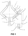
Fig 1 discloses a schematically sectional view of a centrifugal separator having a sensor device according to the invention. -
Fig 2 discloses a schematically sectional view from above of a centrifugal separator. -
Fig 3 discloses a partly sectional side view of a part of the sensor device according to the invention. -
Fig 1 discloses acentrifugal separator 1 having astationary casing 2 and acentrifuge rotor 3 which is provided to rotate around an axis x of rotation in thestationary casing 2. Thecentrifuge rotor 3 is driven via aspindle 4 by a schematically indicateddrive motor 5. Thecentrifugal separator 1 comprises inlet and outlet conduits which are schematically indicated at 6 and which are configured in a manner known per se. - Furthermore, the
centrifuge rotor 3 comprises a plurality ofnozzles 7 for discharge of a product, such as liquid, which for instance may comprise or consist of sludge. Thenozzles 7 may be permanently open nozzles. Thenozzles 7 may alternatively be intermittently openable nozzles which may open in a manner known per se by means of a schematically indicatedvalve disc 8 provided within thecentrifuge rotor 3. Thenozzles 7 are distributed, or preferably uniformly distributed, along the periphery of thecentrifuge rotor 3. Outside thenozzles 7, aguide element 9 is provided. Theguide element 9 is configured to receive and guide the product discharged through thenozzles 7 out of thestationary casing 7 and thecentrifugal separator 1 in a suitable manner. - A sensor device for sensing vibrations and shock pulses is also provided in connection to the
centrifugal separator 1 or is a part of thecentrifugal separator 1. The sensor device comprises atransfer element 21 which is manufactured of a suitable material, for instance a metallic material. - The
transfer element 21 has a first part 21' having an inner end, and asecond part 21" having an outer end, seeFig 2 , and being configured to be mounted to thecentrifugal separator 1 in such a way that the first part 21' and the inner end are located inside thestationary casing 2 and outside thecentrifuge rotor 3, and that thesecond part 21 and the outer end are located outside thestationary casing 2. - In the embodiment disclosed, the
transfer element 21, i.e. both the first part 21' and thesecond part 21 ", has a common elongated or rod like shape. Thetransfer element 21 extends in a longitudinal direction x'. The longitudinal direction x' may be parallel, or substantially parallel, to the axis x of rotation. The longitudinal direction x' may be permitted to form an angle to the axis x of rotation. According to the embodiment inFig 3 thetransfer element 21 may instead extend horizontally in substantially the same direction x" as a nozzle jet passing thetransfer element 21. However, it is possible to merely let the first part 21' have said elongated shape. Thesecond part 21" which is located outside the stationary casing may have any other suitable shape and for instance be angled. Thetransfer element 21 is thus attached to thecentrifugal separator 1 and more precisely in thestationary casing 2. - As can be seen in
fig 3 , thetransfer element 21 comprises a receivinghead 23 which is comprised by the first part 21' and thus is provided at the inner end of thetransfer element 21, and more precisely immediately outside thenozzles 7 of thecentrifuge rotor 3 but inside thestationary casing 2 and theguide element 9. According to the embodiment inFig 3 the receivinghead 23 is the tip of the first part 21' of thetransfer element 21. Parts of the envelope surface of thetransfer element 21 except thereceiving head 23 may be surrounded by a protectingtube 24 which protects the first part 21' of thetransfer element 21 from splashing and vibrations not generated from thereceiving head 23. The protectingtube 24 may thus be suspended by afirst rubber bushing 25 between the same and the first part 21' of thetransfer element 21, close to the receivinghead 23. The protectingtube 24 is also suspended by asecond rubber bushing 26 between the same and thesecond part 21 of thetransfer element 21. Thetransfer element 21 is suspended by saidsecond rubber bushing 26 together with athird bushing 27 between saidtransfer element 21 and acylindrical holder member 22. This will increase the transference of shock pulses through thetransfer element 21 and create a stronger signal through thetransfer element 21. - To mount the
transfer element 21 in thestationary casing 2 of thecentrifugal separator 1 the protectingtube 24 is threaded on its exterior surface which makes it possible to fit in a correspondingly threaded hole in thestationary casing 2. In order to adapt the position of the receivinghead 23 to the nozzle jets, acylindrical spacing sleeve 28 of optional length may be thread on thetransfer element 21 and abut with its first end 28a against a stop 29 on the protectingtube 24 at thesecond part 21" of thetransfer element 21. When thetransfer element 21 is mounted in the hole of thestationary casing 2 the second end 28b of thecylindrical spacing sleeve 28 will rest against the exterior wall of thestationary casing 2, thus defining the position oftransfer element 21 and its receivinghead 23. - The
transfer element 21 may instead be directly mounted in the stationary casing, without the suspension of bushings. - As is disclosed in
fig 2 , in a centrifugal separator with nozzles, thenozzles 7 are usually mounted in thecentrifugal rotor 3 in such a manner that their openings are directed in the rotational direction of therotor 3. The direction may be substantially tangential but preferred is if the openings of thenozzles 7 have a slight outward angle as the jets otherwise may hit the rotor wall and cause abrasive damages. - The
transfer element 21 is mounted in thestationary casing 2 horizontally at the same level as thenozzles 7, directed such that the end face of the receivinghead 23 faces the passing jets from thenozzles 7 during rotation of the rotor. Particularly may thetransfer element 21 be directed such that during rotation the end face of the receivinghead 23 faces the opening of acertain nozzle 7 at a substantially right angle. - The
transfer element 21 will be subjected to erosion from the nozzle jets. It may therefore be manufactured from a wear resistant material or be coated by such a material or surface hardened. - The sensor device also comprises a
sensor element 30 which is mounted to thesecond part 21" of thetransfer element 21, and in the embodiment disclosed in the proximity of the outer end of thetransfer element 21. Thesensor element 30 may comprise or consist of a shock pulse transducer, with an accelerometer, preferably a linear accelerometer. The accelerometer may comprise or consist of a piezoelectric element. Such a piezoelectric element generates a signal in the form of an electric voltage when it is deformed, for instance due to vibrations or shock pulses. The sensor may internally be isolated with a Faraday-shield and have a vibration measuring range of 600 m/s2 and a shock pulse measuring range of -12 to 75 dB. - The sensor device also comprises an
evaluation unit 31 which communicates with thesensor element 30, for instance wirelessly or via aconduit 32, for transferring signals from thesensor element 30 to theevaluation unit 31. Theevaluation unit 31 comprises aprocessor 33 and is configured to interpret the signals generated by thesensor element 30. Theevaluation unit 31 also comprises a display which for instance may include an oscilloscope. Theconduit 32 comprises azener barrier 34. - The
sensor element 30 is configured to sense the vibrations that propagates from the receivinghead 23 to thesensor element 30 via thetransfer element 21. The vibrations propagate in the material of thetransfer element 21. - In the case when the
nozzles 7 are intermittently openable, the sensor device may operate in such a way that when thenozzles 7 during a short time period are opened, the product is discharged at a high velocity from thecentrifuge rotor 3. This product will hit the receivingelement 21 and more precisely the receivinghead 23. Vibrations will then be generated in thetransfer element 21, and these propagate to thesensor element 30. The signals which are then generated by thesensor element 30 are conveyed to theevaluation unit 31 and are processed by theprocessor 33. Theevaluation unit 31 is configured to analyze the signals from thesensor element 30 and to establish a plurality of various parameters and states. The signals obtained may for instance comprise the following parameters: - Peak value
- Rise time
- Fall time
- Width
- Surface.
- By means of these parameters, knowledge about the discharge of the product may be obtained. For instance, it can be mentioned that the surface may be assumed to be proportional to the flow, i.e. the quantity of the product discharged through the
nozzles 7. Theevaluation unit 31 may also be adapted to detect if one or several of thenozzles 7 leaks. If such a leakage arise, a smaller amount of the product will more or less continuously be discharged and hit the receivinghead 23 of thetransfer element 21. Again, vibrations will then be generated and propagate to thesensor element 30 which delivers corresponding signals to theevaluation unit 31. Theevaluation unit 31 may then be configured to give the user information about the present leakage, for instance through any kind of alarm. It is to be noted that the sensor device is very sensitive and that a leakage may be detected at a very early stage, wherein suitable repair measures may be taken. - Furthermore, the sensor device may be used for detecting a possible leakage of the operating liquid used for controlling the position of the
valve disc 8. - It is also to be noted that sensor device and the
evaluation unit 31 may be configured to calculate the rotary speed of the centrifuge rotor by means of the signals from thesensor element 31. In combination with a determination of the rotary speed, the detection of a leakage and possibly also the position of thenozzles 7, it is possible to calculate which of thenozzles 7 possibly leaks by means of theprocessor 33 of theevaluation unit 31. In the case that thenozzles 7 are permanently open, the sensor device and theevaluation unit 31 may be configured to calculate the rotary speed of thecentrifuge rotor 3 by means of the signals from thesensor element 30. Also in this case it is possible to obtain information and knowledge about the discharged product, for instance the discharge direction of the product and the position or path of the product from thenozzles 7, by means of signals from thesensor element 30. The sensor device may in this case also be used for detecting if any of thenozzles 7 is clogged or is beginning to be clogged through a determination of the flow of the product that is discharged. - Finally, it is also to be noted that the sensor device and the
evaluation unit 31 may detect vibrations emanating from other sources than thenozzles 7, for instance various defects in thecentrifugal separator 1 such as play in the bearings etc. It can be assumed that such defects will result in vibrations with other frequencies than those which arise at leakage and discharge of the product, and that these defects thus are possible to detect. - The invention is not limited to the embodiments disclosed but may be modified and varied within the scope of the following claims.
Claims (15)
- A sensor device for a centrifugal separator (1) having a stationary casing (2) and a centrifuge rotor (3), which is provided in the stationary casing (2) and arranged to rotate around an axis (x) of rotation at a rotary speed and which comprises a plurality of nozzles (7) for discharge of a product from the centrifuge rotor (3) in a direction (y), wherein the sensor device comprises a transfer element (21), which has a first part (21') and a second part (21 ") and which is configured to be mounted in such a way that the first part (21') is located inside the stationary casing (2) and outside the centrifuge rotor (3) and that the second part (21 ") is located outside the stationary casing (2), wherein at least the first part (21') of the transfer element (21) has an elongated shape,
a receiving head (23), which is comprised by the first part (21') of the transfer element (21),
a sensor element (30), which is mounted to the second part (21 ") of transfer element (21) and which is configured to sense vibrations and/or shock pulses propagating from the receiving head (23) to the sensor element (30), and
an evaluation unit (31), which communicates with the sensor element (30) for transmitting signals from the sensor element (30) to the evaluation unit (31),
characterized in that the transfer element (21) is mounted in the stationary casing (2), directed such that the end face of the receiving head (23) faces the passing jets from the nozzles (7) during rotation of the rotor. - A sensor device for a centrifugal separator according to claim 1, wherein the transfer element (21) is directed such that during rotation the end face of the receiving head (23) faces the opening of a certain nozzle (7) at a substantially right angle.
- A sensor device according to anyone of the preceding claims, wherein the sensor element (25) is attached to the end of the second part (21 ") of the transfer element (21).
- A sensor device according to anyone of the preceding claims, wherein the transfer element (21) is manufactured of a material configured to permit said propagation of vibrations from the receiving head (23) to sensor element (30).
- A sensor device according to anyone of the preceding claims, wherein the sensor element (25) comprises a shock pulse transducer with an accelerometer.
- A sensor device according to anyone of the preceding claims, wherein the evaluation unit (26) communicates with the sensor element (25) via a conduit (27) comprising a zener barrier (29).
- A sensor device according to anyone of the preceding claims, wherein the evaluation unit (31) is configured to calculate the rotary speed of the centrifuge rotor (3) by means of said signals.
- A sensor device according to anyone of the preceding claims, wherein the nozzles (7) comprise intermittently openable nozzles and wherein the evaluation unit (26) is configured to establish a possible leakage from the nozzles (7) by means of said signals.
- A sensor device according to anyone of the preceding claims, wherein parts of the envelope surface of the transfer element (21) except the receiving head (23) is surrounded by a protecting tube (24) which protects the first part (21') of the transfer element (21) from splashing and vibrations not generated from the receiving head (23).
- A sensor device according to claim 9, wherein the protecting tube (24) is suspended by a first rubber bushing (25) between the protecting tube (24) and the first part (21') of the transfer element (21), close to the receiving head (23).
- A sensor device according to one of claims 9 or 10, wherein the protecting tube (24) is threaded on its exterior surface to fit in a correspondingly threaded hole in the stationary casing (2).
- A sensor device according to one of claim 9, 10 or 11, wherein a cylindrical spacing sleeve (28) of optional length is thread on the transfer element (21) and abuts with its first end (28a) against a stop (29) on the protecting tube (24) at the second part (21 ") of the transfer element (21) and when the transfer element (21) is mounted in the hole of the stationary casing (2) its second end (28b) rests against the exterior wall of the stationary casing (2), thus defining the position of transfer element (21) and its receiving head (23).
- A centrifugal separator having a stationary casing (2) and a centrifuge rotor (3), which is provided in the stationary casing (2) and arranged to rotate around an axis (x) of rotation with a rotary speed and which comprises a plurality of nozzles (7) for discharge of a product from the centrifuge rotor (3), wherein the centrifugal separator comprises a sensor device according to anyone of the preceding claims.
- A centrifugal separator according to claim 13, wherein said nozzles are permanently open.
- A centrifugal separator according to claim 13, wherein said nozzles are intermittently openable.
Priority Applications (7)
| Application Number | Priority Date | Filing Date | Title |
|---|---|---|---|
| HUE16175966A HUE054981T2 (en) | 2016-06-23 | 2016-06-23 | A centrifugal separator with a sensor device |
| EP16175966.7A EP3260205B1 (en) | 2016-06-23 | 2016-06-23 | A centrifugal separator with a sensor device |
| PCT/EP2017/063892 WO2017220330A1 (en) | 2016-06-23 | 2017-06-08 | Centrifugal separator with a sensor device |
| CA3024668A CA3024668C (en) | 2016-06-23 | 2017-06-08 | Centrifugal separator with a sensor device |
| CN201780038734.0A CN109311030A (en) | 2016-06-23 | 2017-06-08 | Whizzer with sensor device |
| BR112018072386-0A BR112018072386B1 (en) | 2016-06-23 | 2017-06-08 | Centrifugal separator. |
| US16/099,592 US11179731B2 (en) | 2016-06-23 | 2017-06-08 | Centrifugal separator with a sensor device |
Applications Claiming Priority (1)
| Application Number | Priority Date | Filing Date | Title |
|---|---|---|---|
| EP16175966.7A EP3260205B1 (en) | 2016-06-23 | 2016-06-23 | A centrifugal separator with a sensor device |
Publications (2)
| Publication Number | Publication Date |
|---|---|
| EP3260205A1 true EP3260205A1 (en) | 2017-12-27 |
| EP3260205B1 EP3260205B1 (en) | 2021-02-24 |
Family
ID=56296511
Family Applications (1)
| Application Number | Title | Priority Date | Filing Date |
|---|---|---|---|
| EP16175966.7A Active EP3260205B1 (en) | 2016-06-23 | 2016-06-23 | A centrifugal separator with a sensor device |
Country Status (7)
| Country | Link |
|---|---|
| US (1) | US11179731B2 (en) |
| EP (1) | EP3260205B1 (en) |
| CN (1) | CN109311030A (en) |
| BR (1) | BR112018072386B1 (en) |
| CA (1) | CA3024668C (en) |
| HU (1) | HUE054981T2 (en) |
| WO (1) | WO2017220330A1 (en) |
Cited By (1)
| Publication number | Priority date | Publication date | Assignee | Title |
|---|---|---|---|---|
| DE102019131509A1 (en) * | 2019-11-21 | 2021-05-27 | Gea Mechanical Equipment Gmbh | Nozzle monitoring device for a nozzle centrifuge, nozzle centrifuge, and method for monitoring nozzles of a nozzle centrifuge |
Families Citing this family (1)
| Publication number | Priority date | Publication date | Assignee | Title |
|---|---|---|---|---|
| USD879170S1 (en) | 2017-06-30 | 2020-03-24 | Gea Mechanical Equipment Gmbh | Centrifugal separator |
Citations (3)
| Publication number | Priority date | Publication date | Assignee | Title |
|---|---|---|---|---|
| US4206871A (en) * | 1977-12-28 | 1980-06-10 | Alfa-Laval Ab | Leakage indicator for centrifuge |
| EP0049089A2 (en) * | 1980-09-26 | 1982-04-07 | Alfa-Laval Ab | Method and apparatus for monitoring operation of a centrifugal separator |
| WO2012158093A1 (en) * | 2011-05-16 | 2012-11-22 | Alfa Laval Corporate Ab | A sensor device for a centrifugal separator and a centrifugal separator with such a sensor. |
Family Cites Families (6)
| Publication number | Priority date | Publication date | Assignee | Title |
|---|---|---|---|---|
| DE3925198A1 (en) | 1988-09-01 | 1990-03-15 | Krauss Maffei Ag | Monitoring successive stages of centrifugal slurry filtration - by vibration sensor mounted on arm pivoting towards sieve surface |
| EP0456861A1 (en) | 1989-07-29 | 1991-11-21 | Krauss-Maffei Aktiengesellschaft | Regulating device for a filtering centrifuge |
| DK2366457T3 (en) * | 2010-03-19 | 2013-06-10 | Alfa Laval Corp Ab | DEVICE AND PROCEDURE FOR MONITORING AND ADJUSTING A RADIAL POSITION OF A INTERFACE LAYER IN A CENTRIFUGE |
| CN102319641A (en) * | 2011-06-16 | 2012-01-18 | 安徽赛而特离心机有限公司 | A kind of disk centrifuge rotary drum protective device |
| CN102669450B (en) | 2012-01-15 | 2013-12-18 | 河南科技大学 | Milk cow energy extender and preparation method thereof |
| DE102013111579A1 (en) | 2013-10-21 | 2015-04-23 | Gea Mechanical Equipment Gmbh | Process for clarifying a flowable product with a centrifuge, in particular a separator |
-
2016
- 2016-06-23 EP EP16175966.7A patent/EP3260205B1/en active Active
- 2016-06-23 HU HUE16175966A patent/HUE054981T2/en unknown
-
2017
- 2017-06-08 CA CA3024668A patent/CA3024668C/en active Active
- 2017-06-08 BR BR112018072386-0A patent/BR112018072386B1/en active IP Right Grant
- 2017-06-08 US US16/099,592 patent/US11179731B2/en active Active
- 2017-06-08 WO PCT/EP2017/063892 patent/WO2017220330A1/en active Application Filing
- 2017-06-08 CN CN201780038734.0A patent/CN109311030A/en active Pending
Patent Citations (3)
| Publication number | Priority date | Publication date | Assignee | Title |
|---|---|---|---|---|
| US4206871A (en) * | 1977-12-28 | 1980-06-10 | Alfa-Laval Ab | Leakage indicator for centrifuge |
| EP0049089A2 (en) * | 1980-09-26 | 1982-04-07 | Alfa-Laval Ab | Method and apparatus for monitoring operation of a centrifugal separator |
| WO2012158093A1 (en) * | 2011-05-16 | 2012-11-22 | Alfa Laval Corporate Ab | A sensor device for a centrifugal separator and a centrifugal separator with such a sensor. |
Cited By (4)
| Publication number | Priority date | Publication date | Assignee | Title |
|---|---|---|---|---|
| DE102019131509A1 (en) * | 2019-11-21 | 2021-05-27 | Gea Mechanical Equipment Gmbh | Nozzle monitoring device for a nozzle centrifuge, nozzle centrifuge, and method for monitoring nozzles of a nozzle centrifuge |
| WO2021099182A1 (en) | 2019-11-21 | 2021-05-27 | Gea Mechanical Equipment Gmbh | Nozzle monitoring device for a nozzle centrifuge, nozzle centrifuge, and method for monitoring nozzles of a nozzle centrifuge |
| CN114728295A (en) * | 2019-11-21 | 2022-07-08 | Gea机械设备有限公司 | Nozzle monitoring device for a nozzle centrifuge, nozzle centrifuge and method for monitoring a nozzle of a nozzle centrifuge |
| CN114728295B (en) * | 2019-11-21 | 2023-11-10 | Gea机械设备有限公司 | Nozzle centrifuge with nozzle monitoring device and method for monitoring nozzle of nozzle centrifuge |
Also Published As
| Publication number | Publication date |
|---|---|
| US20190143342A1 (en) | 2019-05-16 |
| BR112018072386A2 (en) | 2019-02-19 |
| EP3260205B1 (en) | 2021-02-24 |
| CA3024668C (en) | 2021-05-25 |
| BR112018072386B1 (en) | 2022-05-03 |
| CA3024668A1 (en) | 2017-12-28 |
| CN109311030A (en) | 2019-02-05 |
| WO2017220330A1 (en) | 2017-12-28 |
| HUE054981T2 (en) | 2021-10-28 |
| US11179731B2 (en) | 2021-11-23 |
Similar Documents
| Publication | Publication Date | Title |
|---|---|---|
| EP2709767B1 (en) | A sensor device for a centrifugal separator and a centrifugal separator with such a sensor | |
| CA3024668C (en) | Centrifugal separator with a sensor device | |
| US9400229B2 (en) | Apparatus and method for monitoring the state of a roller bearing | |
| CN207749338U (en) | Device for clothing processing | |
| RU2280843C2 (en) | Method and device for inspection of mass discharge of grinded hard material transported along pneumatic line | |
| US8375757B2 (en) | Method for shot peening and a machine therefor | |
| CN107405631B (en) | Whizzer | |
| US4206871A (en) | Leakage indicator for centrifuge | |
| EP0049089B1 (en) | Method and apparatus for monitoring operation of a centrifugal separator | |
| US6062078A (en) | Device for detecting an unbalance in a rotor of a centrifuge | |
| US5369987A (en) | Sealless consistency transmitter | |
| KR102014649B1 (en) | Damper device | |
| JP2020183893A (en) | Torsional vibration detection device, vertical axis pump having the torsional vibration detection device, and torsional vibration detection method | |
| JP4676693B2 (en) | Game machine management device | |
| WO2023088929A1 (en) | Method and apparatus for detecting hydraulic shock | |
| US11913908B2 (en) | Real-time monitoring of mass loss from erosive flow | |
| JP2000074794A (en) | Diagnosis device of abnormality of hydraulic machinery | |
| KR102020375B1 (en) | Flow Sensing Apparatus Having Transferring Member | |
| BR112020022523A2 (en) | non-invasive pipe pig signal using vibration sensors, method for detecting a pipe pig within a pipe and method for determining a signature frequency of a selected length of pipe | |
| NL1022196C2 (en) | Flow meter. | |
| JPH01158296A (en) | Steam trap | |
| EA041151B1 (en) | NON-INTRUSIVE PIG ALARM USING VIBRATION SENSORS | |
| JPH0729061B2 (en) | Rice grain leak detector for rice mill | |
| NO144584B (en) | DETECTOR FOR PARTICLES IN A STREAM IN A PIPE PIPE | |
| MXPA99003265A (en) | Densitometer |
Legal Events
| Date | Code | Title | Description |
|---|---|---|---|
| PUAI | Public reference made under article 153(3) epc to a published international application that has entered the european phase |
Free format text: ORIGINAL CODE: 0009012 |
|
| STAA | Information on the status of an ep patent application or granted ep patent |
Free format text: STATUS: REQUEST FOR EXAMINATION WAS MADE |
|
| 17P | Request for examination filed |
Effective date: 20160623 |
|
| AK | Designated contracting states |
Kind code of ref document: A1 Designated state(s): AL AT BE BG CH CY CZ DE DK EE ES FI FR GB GR HR HU IE IS IT LI LT LU LV MC MK MT NL NO PL PT RO RS SE SI SK SM TR |
|
| AX | Request for extension of the european patent |
Extension state: BA ME |
|
| STAA | Information on the status of an ep patent application or granted ep patent |
Free format text: STATUS: EXAMINATION IS IN PROGRESS |
|
| 17Q | First examination report despatched |
Effective date: 20200401 |
|
| GRAP | Despatch of communication of intention to grant a patent |
Free format text: ORIGINAL CODE: EPIDOSNIGR1 |
|
| STAA | Information on the status of an ep patent application or granted ep patent |
Free format text: STATUS: GRANT OF PATENT IS INTENDED |
|
| RIC1 | Information provided on ipc code assigned before grant |
Ipc: B04B 7/06 20060101AFI20200908BHEP Ipc: B04B 11/04 20060101ALI20200908BHEP Ipc: G01M 3/24 20060101ALI20200908BHEP Ipc: B04B 13/00 20060101ALI20200908BHEP Ipc: B04B 1/10 20060101ALI20200908BHEP Ipc: G01P 15/09 20060101ALI20200908BHEP Ipc: G01P 3/26 20060101ALI20200908BHEP |
|
| INTG | Intention to grant announced |
Effective date: 20201008 |
|
| GRAS | Grant fee paid |
Free format text: ORIGINAL CODE: EPIDOSNIGR3 |
|
| GRAA | (expected) grant |
Free format text: ORIGINAL CODE: 0009210 |
|
| STAA | Information on the status of an ep patent application or granted ep patent |
Free format text: STATUS: THE PATENT HAS BEEN GRANTED |
|
| AK | Designated contracting states |
Kind code of ref document: B1 Designated state(s): AL AT BE BG CH CY CZ DE DK EE ES FI FR GB GR HR HU IE IS IT LI LT LU LV MC MK MT NL NO PL PT RO RS SE SI SK SM TR |
|
| REG | Reference to a national code |
Ref country code: CH Ref legal event code: EP |
|
| REG | Reference to a national code |
Ref country code: DE Ref legal event code: R096 Ref document number: 602016052986 Country of ref document: DE |
|
| REG | Reference to a national code |
Ref country code: AT Ref legal event code: REF Ref document number: 1363788 Country of ref document: AT Kind code of ref document: T Effective date: 20210315 |
|
| REG | Reference to a national code |
Ref country code: IE Ref legal event code: FG4D |
|
| REG | Reference to a national code |
Ref country code: RO Ref legal event code: EPE |
|
| REG | Reference to a national code |
Ref country code: LT Ref legal event code: MG9D |
|
| REG | Reference to a national code |
Ref country code: NL Ref legal event code: MP Effective date: 20210224 |
|
| PG25 | Lapsed in a contracting state [announced via postgrant information from national office to epo] |
Ref country code: BG Free format text: LAPSE BECAUSE OF FAILURE TO SUBMIT A TRANSLATION OF THE DESCRIPTION OR TO PAY THE FEE WITHIN THE PRESCRIBED TIME-LIMIT Effective date: 20210524 Ref country code: HR Free format text: LAPSE BECAUSE OF FAILURE TO SUBMIT A TRANSLATION OF THE DESCRIPTION OR TO PAY THE FEE WITHIN THE PRESCRIBED TIME-LIMIT Effective date: 20210224 Ref country code: GR Free format text: LAPSE BECAUSE OF FAILURE TO SUBMIT A TRANSLATION OF THE DESCRIPTION OR TO PAY THE FEE WITHIN THE PRESCRIBED TIME-LIMIT Effective date: 20210525 Ref country code: FI Free format text: LAPSE BECAUSE OF FAILURE TO SUBMIT A TRANSLATION OF THE DESCRIPTION OR TO PAY THE FEE WITHIN THE PRESCRIBED TIME-LIMIT Effective date: 20210224 Ref country code: LT Free format text: LAPSE BECAUSE OF FAILURE TO SUBMIT A TRANSLATION OF THE DESCRIPTION OR TO PAY THE FEE WITHIN THE PRESCRIBED TIME-LIMIT Effective date: 20210224 Ref country code: PT Free format text: LAPSE BECAUSE OF FAILURE TO SUBMIT A TRANSLATION OF THE DESCRIPTION OR TO PAY THE FEE WITHIN THE PRESCRIBED TIME-LIMIT Effective date: 20210624 Ref country code: NO Free format text: LAPSE BECAUSE OF FAILURE TO SUBMIT A TRANSLATION OF THE DESCRIPTION OR TO PAY THE FEE WITHIN THE PRESCRIBED TIME-LIMIT Effective date: 20210524 |
|
| REG | Reference to a national code |
Ref country code: AT Ref legal event code: MK05 Ref document number: 1363788 Country of ref document: AT Kind code of ref document: T Effective date: 20210224 |
|
| PG25 | Lapsed in a contracting state [announced via postgrant information from national office to epo] |
Ref country code: SE Free format text: LAPSE BECAUSE OF FAILURE TO SUBMIT A TRANSLATION OF THE DESCRIPTION OR TO PAY THE FEE WITHIN THE PRESCRIBED TIME-LIMIT Effective date: 20210224 Ref country code: RS Free format text: LAPSE BECAUSE OF FAILURE TO SUBMIT A TRANSLATION OF THE DESCRIPTION OR TO PAY THE FEE WITHIN THE PRESCRIBED TIME-LIMIT Effective date: 20210224 Ref country code: PL Free format text: LAPSE BECAUSE OF FAILURE TO SUBMIT A TRANSLATION OF THE DESCRIPTION OR TO PAY THE FEE WITHIN THE PRESCRIBED TIME-LIMIT Effective date: 20210224 Ref country code: LV Free format text: LAPSE BECAUSE OF FAILURE TO SUBMIT A TRANSLATION OF THE DESCRIPTION OR TO PAY THE FEE WITHIN THE PRESCRIBED TIME-LIMIT Effective date: 20210224 Ref country code: NL Free format text: LAPSE BECAUSE OF FAILURE TO SUBMIT A TRANSLATION OF THE DESCRIPTION OR TO PAY THE FEE WITHIN THE PRESCRIBED TIME-LIMIT Effective date: 20210224 |
|
| PG25 | Lapsed in a contracting state [announced via postgrant information from national office to epo] |
Ref country code: IS Free format text: LAPSE BECAUSE OF FAILURE TO SUBMIT A TRANSLATION OF THE DESCRIPTION OR TO PAY THE FEE WITHIN THE PRESCRIBED TIME-LIMIT Effective date: 20210624 |
|
| REG | Reference to a national code |
Ref country code: HU Ref legal event code: AG4A Ref document number: E054981 Country of ref document: HU |
|
| PG25 | Lapsed in a contracting state [announced via postgrant information from national office to epo] |
Ref country code: SM Free format text: LAPSE BECAUSE OF FAILURE TO SUBMIT A TRANSLATION OF THE DESCRIPTION OR TO PAY THE FEE WITHIN THE PRESCRIBED TIME-LIMIT Effective date: 20210224 Ref country code: AT Free format text: LAPSE BECAUSE OF FAILURE TO SUBMIT A TRANSLATION OF THE DESCRIPTION OR TO PAY THE FEE WITHIN THE PRESCRIBED TIME-LIMIT Effective date: 20210224 Ref country code: CZ Free format text: LAPSE BECAUSE OF FAILURE TO SUBMIT A TRANSLATION OF THE DESCRIPTION OR TO PAY THE FEE WITHIN THE PRESCRIBED TIME-LIMIT Effective date: 20210224 Ref country code: EE Free format text: LAPSE BECAUSE OF FAILURE TO SUBMIT A TRANSLATION OF THE DESCRIPTION OR TO PAY THE FEE WITHIN THE PRESCRIBED TIME-LIMIT Effective date: 20210224 |
|
| REG | Reference to a national code |
Ref country code: DE Ref legal event code: R097 Ref document number: 602016052986 Country of ref document: DE |
|
| PG25 | Lapsed in a contracting state [announced via postgrant information from national office to epo] |
Ref country code: SK Free format text: LAPSE BECAUSE OF FAILURE TO SUBMIT A TRANSLATION OF THE DESCRIPTION OR TO PAY THE FEE WITHIN THE PRESCRIBED TIME-LIMIT Effective date: 20210224 Ref country code: DK Free format text: LAPSE BECAUSE OF FAILURE TO SUBMIT A TRANSLATION OF THE DESCRIPTION OR TO PAY THE FEE WITHIN THE PRESCRIBED TIME-LIMIT Effective date: 20210224 |
|
| PLBE | No opposition filed within time limit |
Free format text: ORIGINAL CODE: 0009261 |
|
| STAA | Information on the status of an ep patent application or granted ep patent |
Free format text: STATUS: NO OPPOSITION FILED WITHIN TIME LIMIT |
|
| PG25 | Lapsed in a contracting state [announced via postgrant information from national office to epo] |
Ref country code: AL Free format text: LAPSE BECAUSE OF FAILURE TO SUBMIT A TRANSLATION OF THE DESCRIPTION OR TO PAY THE FEE WITHIN THE PRESCRIBED TIME-LIMIT Effective date: 20210224 Ref country code: MC Free format text: LAPSE BECAUSE OF FAILURE TO SUBMIT A TRANSLATION OF THE DESCRIPTION OR TO PAY THE FEE WITHIN THE PRESCRIBED TIME-LIMIT Effective date: 20210224 Ref country code: ES Free format text: LAPSE BECAUSE OF FAILURE TO SUBMIT A TRANSLATION OF THE DESCRIPTION OR TO PAY THE FEE WITHIN THE PRESCRIBED TIME-LIMIT Effective date: 20210224 |
|
| REG | Reference to a national code |
Ref country code: CH Ref legal event code: PL |
|
| 26N | No opposition filed |
Effective date: 20211125 |
|
| GBPC | Gb: european patent ceased through non-payment of renewal fee |
Effective date: 20210623 |
|
| PG25 | Lapsed in a contracting state [announced via postgrant information from national office to epo] |
Ref country code: SI Free format text: LAPSE BECAUSE OF FAILURE TO SUBMIT A TRANSLATION OF THE DESCRIPTION OR TO PAY THE FEE WITHIN THE PRESCRIBED TIME-LIMIT Effective date: 20210224 |
|
| REG | Reference to a national code |
Ref country code: BE Ref legal event code: MM Effective date: 20210630 |
|
| PG25 | Lapsed in a contracting state [announced via postgrant information from national office to epo] |
Ref country code: LU Free format text: LAPSE BECAUSE OF NON-PAYMENT OF DUE FEES Effective date: 20210623 |
|
| PG25 | Lapsed in a contracting state [announced via postgrant information from national office to epo] |
Ref country code: LI Free format text: LAPSE BECAUSE OF NON-PAYMENT OF DUE FEES Effective date: 20210630 Ref country code: IT Free format text: LAPSE BECAUSE OF FAILURE TO SUBMIT A TRANSLATION OF THE DESCRIPTION OR TO PAY THE FEE WITHIN THE PRESCRIBED TIME-LIMIT Effective date: 20210224 Ref country code: IE Free format text: LAPSE BECAUSE OF NON-PAYMENT OF DUE FEES Effective date: 20210623 Ref country code: GB Free format text: LAPSE BECAUSE OF NON-PAYMENT OF DUE FEES Effective date: 20210623 Ref country code: CH Free format text: LAPSE BECAUSE OF NON-PAYMENT OF DUE FEES Effective date: 20210630 |
|
| PG25 | Lapsed in a contracting state [announced via postgrant information from national office to epo] |
Ref country code: IS Free format text: LAPSE BECAUSE OF FAILURE TO SUBMIT A TRANSLATION OF THE DESCRIPTION OR TO PAY THE FEE WITHIN THE PRESCRIBED TIME-LIMIT Effective date: 20210624 |
|
| PG25 | Lapsed in a contracting state [announced via postgrant information from national office to epo] |
Ref country code: BE Free format text: LAPSE BECAUSE OF NON-PAYMENT OF DUE FEES Effective date: 20210630 |
|
| P01 | Opt-out of the competence of the unified patent court (upc) registered |
Effective date: 20230420 |
|
| PG25 | Lapsed in a contracting state [announced via postgrant information from national office to epo] |
Ref country code: CY Free format text: LAPSE BECAUSE OF FAILURE TO SUBMIT A TRANSLATION OF THE DESCRIPTION OR TO PAY THE FEE WITHIN THE PRESCRIBED TIME-LIMIT Effective date: 20210224 |
|
| PGFP | Annual fee paid to national office [announced via postgrant information from national office to epo] |
Ref country code: RO Payment date: 20230529 Year of fee payment: 8 Ref country code: FR Payment date: 20230510 Year of fee payment: 8 Ref country code: DE Payment date: 20230425 Year of fee payment: 8 |
|
| PGFP | Annual fee paid to national office [announced via postgrant information from national office to epo] |
Ref country code: HU Payment date: 20230515 Year of fee payment: 8 |
|
| PG25 | Lapsed in a contracting state [announced via postgrant information from national office to epo] |
Ref country code: MK Free format text: LAPSE BECAUSE OF FAILURE TO SUBMIT A TRANSLATION OF THE DESCRIPTION OR TO PAY THE FEE WITHIN THE PRESCRIBED TIME-LIMIT Effective date: 20210224 |