EP3260144A1 - Systems for collecting exudates in reduced-pressure therapy - Google Patents
Systems for collecting exudates in reduced-pressure therapy Download PDFInfo
- Publication number
- EP3260144A1 EP3260144A1 EP17179395.3A EP17179395A EP3260144A1 EP 3260144 A1 EP3260144 A1 EP 3260144A1 EP 17179395 A EP17179395 A EP 17179395A EP 3260144 A1 EP3260144 A1 EP 3260144A1
- Authority
- EP
- European Patent Office
- Prior art keywords
- reduced
- connector
- dressing
- interface
- container
- Prior art date
- Legal status (The legal status is an assumption and is not a legal conclusion. Google has not performed a legal analysis and makes no representation as to the accuracy of the status listed.)
- Granted
Links
Images



Classifications
-
- A—HUMAN NECESSITIES
- A61—MEDICAL OR VETERINARY SCIENCE; HYGIENE
- A61M—DEVICES FOR INTRODUCING MEDIA INTO, OR ONTO, THE BODY; DEVICES FOR TRANSDUCING BODY MEDIA OR FOR TAKING MEDIA FROM THE BODY; DEVICES FOR PRODUCING OR ENDING SLEEP OR STUPOR
- A61M1/00—Suction or pumping devices for medical purposes; Devices for carrying-off, for treatment of, or for carrying-over, body-liquids; Drainage systems
- A61M1/71—Suction drainage systems
- A61M1/78—Means for preventing overflow or contamination of the pumping systems
- A61M1/784—Means for preventing overflow or contamination of the pumping systems by filtering, sterilising or disinfecting the exhaust air, e.g. swellable filter valves
-
- A—HUMAN NECESSITIES
- A61—MEDICAL OR VETERINARY SCIENCE; HYGIENE
- A61M—DEVICES FOR INTRODUCING MEDIA INTO, OR ONTO, THE BODY; DEVICES FOR TRANSDUCING BODY MEDIA OR FOR TAKING MEDIA FROM THE BODY; DEVICES FOR PRODUCING OR ENDING SLEEP OR STUPOR
- A61M1/00—Suction or pumping devices for medical purposes; Devices for carrying-off, for treatment of, or for carrying-over, body-liquids; Drainage systems
- A61M1/90—Negative pressure wound therapy devices, i.e. devices for applying suction to a wound to promote healing, e.g. including a vacuum dressing
- A61M1/98—Containers specifically adapted for negative pressure wound therapy
-
- A—HUMAN NECESSITIES
- A61—MEDICAL OR VETERINARY SCIENCE; HYGIENE
- A61F—FILTERS IMPLANTABLE INTO BLOOD VESSELS; PROSTHESES; DEVICES PROVIDING PATENCY TO, OR PREVENTING COLLAPSING OF, TUBULAR STRUCTURES OF THE BODY, e.g. STENTS; ORTHOPAEDIC, NURSING OR CONTRACEPTIVE DEVICES; FOMENTATION; TREATMENT OR PROTECTION OF EYES OR EARS; BANDAGES, DRESSINGS OR ABSORBENT PADS; FIRST-AID KITS
- A61F13/00—Bandages or dressings; Absorbent pads
- A61F13/05—Bandages or dressings; Absorbent pads specially adapted for use with sub-pressure or over-pressure therapy, wound drainage or wound irrigation, e.g. for use with negative-pressure wound therapy [NPWT]
-
- A—HUMAN NECESSITIES
- A61—MEDICAL OR VETERINARY SCIENCE; HYGIENE
- A61M—DEVICES FOR INTRODUCING MEDIA INTO, OR ONTO, THE BODY; DEVICES FOR TRANSDUCING BODY MEDIA OR FOR TAKING MEDIA FROM THE BODY; DEVICES FOR PRODUCING OR ENDING SLEEP OR STUPOR
- A61M27/00—Drainage appliance for wounds or the like, i.e. wound drains, implanted drains
-
- A—HUMAN NECESSITIES
- A61—MEDICAL OR VETERINARY SCIENCE; HYGIENE
- A61M—DEVICES FOR INTRODUCING MEDIA INTO, OR ONTO, THE BODY; DEVICES FOR TRANSDUCING BODY MEDIA OR FOR TAKING MEDIA FROM THE BODY; DEVICES FOR PRODUCING OR ENDING SLEEP OR STUPOR
- A61M2209/00—Ancillary equipment
- A61M2209/08—Supports for equipment
- A61M2209/084—Supporting bases, stands for equipment
- A61M2209/086—Docking stations
-
- Y—GENERAL TAGGING OF NEW TECHNOLOGICAL DEVELOPMENTS; GENERAL TAGGING OF CROSS-SECTIONAL TECHNOLOGIES SPANNING OVER SEVERAL SECTIONS OF THE IPC; TECHNICAL SUBJECTS COVERED BY FORMER USPC CROSS-REFERENCE ART COLLECTIONS [XRACs] AND DIGESTS
- Y10—TECHNICAL SUBJECTS COVERED BY FORMER USPC
- Y10T—TECHNICAL SUBJECTS COVERED BY FORMER US CLASSIFICATION
- Y10T156/00—Adhesive bonding and miscellaneous chemical manufacture
- Y10T156/10—Methods of surface bonding and/or assembly therefor
-
- Y—GENERAL TAGGING OF NEW TECHNOLOGICAL DEVELOPMENTS; GENERAL TAGGING OF CROSS-SECTIONAL TECHNOLOGIES SPANNING OVER SEVERAL SECTIONS OF THE IPC; TECHNICAL SUBJECTS COVERED BY FORMER USPC CROSS-REFERENCE ART COLLECTIONS [XRACs] AND DIGESTS
- Y10—TECHNICAL SUBJECTS COVERED BY FORMER USPC
- Y10T—TECHNICAL SUBJECTS COVERED BY FORMER US CLASSIFICATION
- Y10T29/00—Metal working
- Y10T29/49—Method of mechanical manufacture
- Y10T29/49826—Assembling or joining
Definitions
- the present invention relates generally to tissue treatment systems and more particularly to systems and methods for collecting exudates in reduced-pressure therapy.
- Reduced-pressure wound therapy may provide a number of benefits, including migration of epithelial and subcutaneous tissues, improved blood flow, and micro-deformation of tissue at a wound site. Together, these benefits can increase development of granulation tissue and reduce healing times.
- a dressing connector is described herein that provides a first fluid path between a first connector and a second connector, and a second fluid path between a third connector and a fourth connector.
- a liquid barrier may be disposed in the first fluid path. The first fluid path and the second fluid path are generally exposed to an exterior surface of the dressing connector.
- the first connector may be a fitting
- the second connector may be a receptacle
- the third connector may be a port
- the fourth connector may be another receptacle.
- a tube may also be bonded to the third connector to provide a third fluid path between the dressing connector and another component.
- the liquid barrier may be a filter, such as a hydrophobic bacterial filter, a gel-blocking sintered polymer filter, and/or a charcoal filter.
- an example embodiment may provide a fitting fluidly coupled to a first receptacle through an inline liquid barrier, a port fluidly coupled to a second receptacle, and a tube fluidly coupled to the port.
- the fitting may be adapted to engage a downstream component, such as a reduced-pressure source.
- the first receptacle and the second receptacle each may provide a cavity exposed to an exterior surface adapted to engage a container fitting.
- a reduced-pressure treatment system is also described herein, wherein one example embodiment includes a downstream component, such as a reduced-pressure source, a reusable container, and a disposable dressing connector.
- the dressing connector may be coupled to the container and to an upstream component, such as a dressing.
- the dressing connector provides a first fluid path between the downstream component and the container, and a second fluid path between the container and the upstream component.
- a liquid barrier can be disposed in the first fluid path between the container and the downstream component.
- a tube may couple the dressing connector to the downstream component, the upstream component, or both.
- a method of manufacturing a dressing component is also described herein, wherein one example embodiment includes forming a first interface comprising a first port, a second port, a first receptacle, and a second receptacle.
- a first channel may be formed from the first port to the first receptacle.
- a second channel may be formed from the second port to the second receptacle.
- a tube may be coupled to the first port, such as by bonding the tube to the first port with an adhesive.
- a second interface may be formed with a third port and a fitting. The second port and the third port may be aligned and a liquid barrier disposed between the second port and the third port before coupling the first interface to the second interface.
- a dressing may be coupled to a first dressing connector.
- a dressing may be applied to a tissue site and a tube may be coupled to the dressing and to the first dressing connector.
- the first dressing connector may then be coupled to a reusable fluid container, such as by pressing receptacles of the first dressing connector onto fittings of the fluid container.
- orientation recesses of the first dressing connector may also be aligned with corresponding orientation fittings on the fluid container.
- the fluid container and the first dressing connector can then be coupled to a reduced-pressure source or other downstream component, such that a liquid barrier in the first dressing connector can be positioned between the fluid container and the reduced-pressure source. Reduced pressure can be applied to a tissue site through the dressing.
- Reduced-pressure may be applied and exudates collected from the tissue site in the fluid container. Exudates may be emptied from the fluid container and the first dressing connector may be replaced with a second dressing connector having a second (and preferably unused) liquid barrier.
- the first dressing connector can be disposed of with the dressing, which encourages regular changes of liquid barriers.
- FIGS 1A-1B are simplified functional block diagrams of example embodiments of a reduced-pressure therapy system 100 that can collect exudates in accordance with this specification.
- reduced-pressure therapy system 100 may include a dressing 102 fluidly coupled to a reduced-pressure source 104.
- a regulator or controller, such as regulator 106 may also be fluidly coupled to dressing 102 and reduced-pressure source 104.
- Dressing 102 generally includes a drape, such as drape 108, and a manifold, such as pressure distribution manifold 110.
- Reduced-pressure therapy system 100 may also include fluid container, such as container 112, coupled to dressing 102 and reduced-pressure source 104.
- components of reduced-pressure therapy system 100 may be coupled directly or indirectly.
- reduced-pressure source 104 may be directly coupled to regulator 106 and indirectly coupled to dressing 102 through regulator 106.
- Components may be fluidly coupled to each other to provide a path for transferring fluids (i.e., liquid and/or gas) between the components.
- components may be fluidly coupled with a tube, for example.
- a tube is an elongated, cylindrical structure with some flexibility, but the geometry and rigidity may vary.
- components may additionally or alternatively be coupled by virtue of physical proximity, being integral to a single structure, or being formed from the same piece of material. Coupling may also include mechanical, thermal, electrical, or chemical coupling (such as a chemical bond) in some contexts.
- pressure distribution manifold 110 may be placed within, over, on, or otherwise proximate to a tissue site.
- Drape 108 may be placed over pressure distribution manifold 110 and sealed to tissue proximate the tissue site.
- the tissue proximate to the tissue site is often undamaged epidermis peripheral to the tissue site.
- dressing 102 can provide a sealed therapeutic environment proximate to a tissue site, substantially isolated from the external environment, and reduced-pressure source 104 can reduce the pressure in the sealed therapeutic environment.
- Reduced pressure applied uniformly through pressure distribution manifold 110 in the sealed therapeutic environment can induce macrostrain and microstrain in the tissue site, as well as remove exudates and other fluids from the tissue site, which can be collected in container 112 and disposed of properly.
- the fluid mechanics of using a reduced-pressure source to reduce pressure in another component or location, such as within a sealed therapeutic environment, can be mathematically complex.
- the basic principles of fluid mechanics applicable to reduced-pressure therapy are generally well-known to those skilled in the art, and the process of reducing pressure may be described illustratively herein as "delivering,” “distributing,” or “generating” reduced pressure, for example.
- exudates and other fluids flow toward lower pressure along a fluid path.
- This orientation is generally presumed for purposes of describing various features and components of reduced-pressure therapy systems herein.
- downstream typically implies something in a fluid path relatively closer to a reduced-pressure source
- upstream implies something relatively further away from a reduced-pressure source.
- the fluid path may also be reversed in some applications (such as by substituting a positive-pressure source for a reduced-pressure source) and this descriptive convention should not be construed as a limiting convention.
- tissue site in this context broadly refers to a wound or defect located on or within tissue, including but not limited to, bone tissue, adipose tissue, muscle tissue, neural tissue, dermal tissue, vascular tissue, connective tissue, cartilage, tendons, or ligaments.
- a wound may include chronic, acute, traumatic, subacute, and dehisced wounds, partial-thickness bums, ulcers (such as diabetic, pressure, or venous insufficiency ulcers), flaps, and grafts, for example.
- tissue site may also refer to areas of any tissue that are not necessarily wounded or defective, but are instead areas in which it may be desirable to add or promote the growth of additional tissue. For example, reduced pressure may be used in certain tissue areas to grow additional tissue that may be harvested and transplanted to another tissue location.
- Reduced pressure generally refers to a pressure less than a local ambient pressure, such as the ambient pressure in a local environment external to a sealed therapeutic environment provided by dressing 102.
- the local ambient pressure may also be the atmospheric pressure at which a patient is located.
- the pressure may be less than a hydrostatic pressure associated with tissue at the tissue site. Unless otherwise indicated, values of pressure stated herein are gauge pressures.
- references to increases in reduced pressure typically refer to a decrease in absolute pressure, while decreases in reduced pressure typically refer to an increase in absolute pressure.
- a reduced-pressure source such as reduced-pressure source 104, may be a reservoir of air at a reduced pressure, or may be a manual or electrically-powered device that can reduced the pressure in a sealed volume, such as a vacuum pump, a suction pump, a wall suction port available at many healthcare facilities, or a micro-pump, for example.
- the reduced-pressure source may be housed within or used in conjunction with other components, such as sensors, processing units, alarm indicators, memory, databases, software, display devices, or user interfaces that further facilitate reduced-pressure therapy. While the amount and nature of reduced pressure applied to a tissue site may vary according to therapeutic requirements, the pressure typically ranges between -5 mm Hg (-667 Pa) and -500 mm Hg (-66.7 kPa). Common therapeutic ranges are between -75 mm Hg (-9.9 kPa) and -300 mm Hg (-39.9 kPa).
- Pressure distribution manifold 110 can be generally adapted to contact a tissue site. Pressure distribution manifold 110 may be partially or fully in contact with the tissue site. If the tissue site is a wound, for example, pressure distribution manifold 110 may partially or completely fill the wound, or may be placed over the wound. Pressure distribution manifold 110 may take many forms, and may have many sizes, shapes, or thicknesses depending on a variety of factors, such as the type of treatment being implemented or the nature and size of a tissue site. For example, the size and shape of pressure distribution manifold 110 may be adapted to the contours of deep and irregular shaped tissue sites.
- a manifold is a substance or structure adapted to distribute reduced pressure to and/or remove fluids from a tissue site, or both.
- a manifold may also facilitate delivering fluids to a tissue site, if the fluid path is reversed or a secondary fluid path is provided, for example.
- a manifold may include flow channels or pathways that distribute fluids provided to and removed from a tissue site around the manifold.
- the flow channels or pathways may be interconnected to improve distribution of fluids provided to or removed from a tissue site.
- cellular foam, open-cell foam, porous tissue collections, and other porous material such as gauze or felted mat generally include structural elements arranged to form flow channels. Liquids, gels, and other foams may also include or be cured to include flow channels.
- pressure distribution manifold 110 may be a porous foam material having interconnected cells or pores adapted to uniformly (or quasi-uniformly) distribute reduced pressure to a tissue site.
- the foam material may be either hydrophobic or hydrophilic.
- pressure distribution manifold 110 can be an open-cell, reticulated polyurethane foam such as GranuFoam ® dressing available from Kinetic Concepts, Inc. of San Antonio, Texas.
- pressure distribution manifold 110 may be made from a hydrophilic material
- pressure distribution manifold 110 may also wick fluid away from a tissue site, while continuing to distribute reduced pressure to the tissue site.
- the wicking properties of pressure distribution manifold 110 may draw fluid away from a tissue site by capillary flow or other wicking mechanisms.
- An example of a hydrophilic foam is a polyvinyl alcohol, open-cell foam such as V.A.C. WhiteFoam ® dressing available from Kinetic Concepts, Inc. of San Antonio, Texas.
- Other hydrophilic foams may include those made from polyether.
- Other foams that may exhibit hydrophilic characteristics include hydrophobic foams that have been treated or coated to provide hydrophilicity.
- Pressure distribution manifold 110 may further promote granulation at a tissue site when pressure within the sealed therapeutic environment is reduced.
- any or all of the surfaces of pressure distribution manifold 110 may have an uneven, coarse, or jagged profile that can induce microstrains and stresses at a tissue site if reduced pressure is applied through pressure distribution manifold 110.
- pressure distribution manifold 110 may be constructed from bioresorbable materials. Suitable bioresorbable materials may include, without limitation, a polymeric blend of polylactic acid (PLA) and polyglycolic acid (PGA). The polymeric blend may also include without limitation polycarbonates, polyfumarates, and capralactones. Pressure distribution manifold 110 may further serve as a scaffold for new cell-growth, or a scaffold material may be used in conjunction with pressure distribution manifold 110 to promote cell-growth.
- a scaffold is generally a substance or structure used to enhance or promote the growth of cells or formation of tissue, such as a three-dimensional porous structure that provides a template for cell growth.
- Illustrative examples of scaffold materials include calcium phosphate, collagen, PLA/PGA, coral hydroxy apatites, carbonates, or processed allograft materials.
- Drape 108 is an example of a sealing member.
- a sealing member may be constructed from a material that can provide a fluid seal between two components or two environments, such as between a therapeutic environment and a local external environment.
- the sealing member may be, for example, an impermeable or semi-permeable, elastomeric material that can provide a seal adequate to maintain a reduced pressure at a tissue site for a given reduced-pressure source.
- the permeability generally should be low enough that a desired reduced pressure may be maintained.
- An attachment device may be used to attach a sealing member to an attachment surface, such as undamaged epidermis, a gasket, or another sealing member.
- the attachment device may take many forms.
- an attachment device may be a medically-acceptable, pressure-sensitive adhesive that extends about a periphery, a portion, or an entire sealing member.
- Other example embodiments of an attachment device may include a double-sided tape, paste, hydrocolloid, hydrogel, silicone gel, organogel, or an acrylic adhesive.
- Container 112 is representative of a container, canister, pouch, or other storage component that can be used to manage exudates and other fluids withdrawn from a tissue site.
- a rigid container may be preferred or required for collecting, storing, and disposing of fluids.
- fluids may be properly disposed of without rigid container storage, and a re-usable container could reduce waste and costs associated with reduced-pressure therapy.
- Liquid barriers are usually an integral part of most reduced-pressure therapy containers, though. For example, certain filters can reduce odor and prevent exudates from entering the reduced-pressure source and other components downstream from the container. In general, liquid barriers allow air to flow from the container to the reduced-pressure source while preventing contamination. However, protein deposits can accumulate on the liquid barriers and gradually reduce the volume of air flowing from the container, which can adversely affect therapy and cause false blockage alarms. Consequently, filters can be a limiting factor for re-using a container.
- reduced-pressure therapy system 100 can overcome these shortcomings and others by providing a re-usable container for collecting exudates that ensures filter changes at regular intervals.
- container 112 may be a re-usable fluid container, and a single- use dressing connector, such as connector 114, may couple container 112 to dressing 102 and reduced-pressure source 104.
- the dressing connector includes an integrated, inline liquid barrier and provides two pneumatic pathways. In general, the first pneumatic pathway can connect the dressing to the fluid container, and the second pneumatic pathway can connect the fluid container to the reduced-pressure source or other downstream components, through the liquid barrier.
- the dressing connector may also include a tube having one end bonded or semi-permanently coupled to the first pneumatic pathway. The other end of the tube can be connected to the dressing during therapy.
- the second pneumatic pathway may be directly coupled to a reduced-pressure source through a port adapted for mating with the reduced-pressure source, while in other embodiments the second pneumatic pathway may be indirectly coupled to a reduced-pressure source through one or more intermediate components.
- the fluid container may also include a drain port with a drain cover that may be removed and replaced.
- the fluid container may be a rigid canister in some embodiments, but may be a flexible container such as a soft-sided pouch in other embodiments.
- reduced-pressure therapy may be applied until a dressing requires replacement or therapy is complete.
- the fluid container may be emptied and the dressing connector (with the integrated liquid barrier) can be disposed of with the dressing. Consequently, the liquid barrier may only be used for a fixed duration or for a fixed volume of exudates, which substantially reduces or eliminates cross-contamination between patients (as a dressing should not be used on multiple patients) and blockages due to extended use by a single patient.
- FIG. 2 is a schematic diagram illustrating additional details that may be associated with an example embodiment of reduced-pressure therapy system 100.
- reduced-pressure therapy system 100 generally includes a dressing 202 fluidly coupled to a container, such as canister 204, through a tube 206 and dressing connector 208.
- a dressing interface (not shown) may facilitate coupling dressing 202 and tube 206.
- a dressing interface may be a T.R.A.C. ® Pad or Sensa T.R.A.C. ® Pad available from KCI of San Antonio, Texas.
- the dressing interface may be a portion of tube 206 extending into the sealed therapeutic environment, or may be a vacuum port on a micro-pump that extends into the sealed therapeutic environment.
- Dressing connector 208 in this example embodiment can be directly coupled to a reduced-pressure source 210.
- canister 204 can be fluidly coupled to both dressing 202 and reduced-pressure source 210.
- Canister 204 and reduced-pressure source 210 may additionally be mechanically coupled to increase stability, such as with a fastener or interlocking features.
- dressing 202 may be applied to a tissue site 212, and exudates 214 may be removed from the tissue site 212 and collected in canister 204 as reduced-pressure therapy is applied. In general, exudates and other fluids flow toward lower pressure along a fluid path 216.
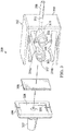
- FIG 3 is an exploded diagram illustrating additional details that may be associated with an example embodiment of dressing connector 208.
- dressing connector 208 generally includes interfaces 302-304 and a liquid barrier 306.
- Interface 302 may be generally described as a "container interface" that provides connectors, fasteners, or fittings adapted to mate with corresponding connectors, fasteners, or fittings of another component, particularly a fluid container.
- interface 302 is illustrated with three female connectors, i.e., receptacles 308-310 and a port 312, but other combinations of male and female connectors are also possible.
- Interface 302 may additionally provide one or more orientation guides, such as orientation recesses 314a-314b.
- Receptacles 308-310, port 312, and orientation recesses 314a-314b are generally exposed to an exterior surface 315 of dressing connector 208.
- receptacles 308-310 are exposed on a first side of exterior surface 315 and port 312 is exposed on a second, adjacent side.
- receptacles 308-310 may be generally described as cavities exposed to exterior surface 315 and adapted to receive and hold a male connector.
- receptacle 308 may be an inlet receptacle adapted to receive fluid flow from an outlet fitting of a container, and receptacle 310 may be an outlet receptacle adapted to exhaust fluid flow into the container.
- a channel 316 may fluidly couple receptacle 308 to an aperture 317, and a channel 318 may fluidly couple receptacle 310 to port 312.
- Tube 206 may be bonded or semi-permanently attached to port 312 to prevent separation under expected therapeutic conditions.
- tube 206 may be bonded to port 312 with an adhesive, glue, or cement, or tube 206 and port 312 may be sized to provide a press fit.
- Interface 304 may be generally described as a "downstream interface" that provides an aperture 320 adapted for fluid communication with channel 316 and a connector adapted to engage a downstream component.
- the connector is represented as a fitting 322 that may be adapted to mechanically couple with reduced-pressure source 210.
- fitting 322 is a male fitting (i.e., a part bearing one or more protrusions) adapted to engage a female fitting or receptacle, but in other embodiments, fitting 322 may be a female fitting adapted to engage a male fitting, for example.
- Interface 304 may additionally include a recess 324 adapted to receive liquid barrier 306.
- tube 206 can be fluidly coupled to port 312 (i.e., through a lumen in tube 206) and port 312 can be fluidly coupled to receptacle 310 (i.e., through channel 318).
- aperture 320 may be aligned with aperture 317 to fluidly couple fitting 322 to receptacle 316 through liquid barrier 306.
- liquid barrier 306 may be a hydrophobic, bacterial filter.
- a charcoal filter may also be co-located or placed inline with the hydrophobic, bacterial filter to reduce odor.
- liquid barrier 306 may be a gel-blocking sintered polymer filter that swells on contact with water, which can block the fluid path between a reduced-pressure source and a canister.
- Suitable polymers include, for example, fluoropolymers such as polytetrafluoroethylene (PTFE), polyvinylidene fluoride (PVdF), or fluorinated ethylenepropylene (FEP); chlorofluoropolymers, such as polychlorotrifluoroethylene (PCTFE); polyolefins such as high density polyethylene (HDPE), polypropylene (PP), cyclic olefin copolymer (COC), or polymethylpent-1-ene (PMP); polyvinyl acetate (PVAc) or ethylene vinyl acetate (EVA); polycarbonate (PC); polyesters such as polyethylene terephthalate (PET) or PET copolymers (PETG); or polysulphones or polyethersulphones.
- fluoropolymers such as polytetrafluoroethylene (PTFE), polyvinylidene fluoride (PVdF), or fluorinated ethylenepropylene (FEP);
- the polymer may also contain charcoal to reduce odor. Additionally, filters may be coated to enhance hydrophobicity in some embodiments. Polymers may be formed into membranes or sintered (particularly for PVAc, EVA, polyolefin's, and fluoropolymers).
- interface 302 and interface 304 are illustrated as separate components that may be bonded together to enclose liquid barrier 306.
- dressing connector 208 may be fabricated from a single mold in which interface 302 and interface 304 form a unitary structure.
- Liquid barrier 306 in this instance may be formed from a sintered polymer, for example, that can be inserted into port 322 of the unitary structure consisting of 302 and 304. This type of assembly may also suit a more common sheet filter welded or glued to a molded carrier that can also be pushed into port 322. Liquid barrier 306 may also be welded or glued directly to a singular unitary structure consisting of 302 and 304.
- a first interface (such as interface 302) may be formed with a first port (such as port 312), a second port, a first receptacle (such as receptacle 310), and a second receptacle (such as receptacle 308).
- a first channel such as channel 318, may be formed from the first port to the first receptacle.
- a second channel such as channel 316, may be formed from the second port to the second receptacle.
- a tube such as tube 206 may be coupled to the first port, such as by bonding the tube to the first port with an adhesive.
- a second interface (such as interface 304) may be formed with a third port (such as aperture 320) and a fitting (such as fitting 322).
- the second port and the third port may be aligned and a liquid barrier disposed between the second port and the third port before coupling the first interface to the second interface.
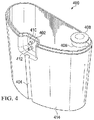
- Figure 4 is a perspective view of a container that may be associated with example embodiments of reduced-pressure therapy system 100.
- the container may be a rigid canister 400 that generally includes an interface 402, an alignment recess 404, a drain port 406, and a drain cover 408.
- Interface 402 may be described as a "connector interface" that can be recessed in the body 414 of rigid canister 400 and adapted for fluidly coupling with a dressing connector, such as interface 302 of dressing connector 208.
- interface 402 may provide fittings 410-412, which can be adapted for coupling to receptacles 308-310, and may be dimensioned and recessed within body 414 of canister 400 to minimize the profile of dressing connector 208.
- alignment recess 404 may be dimensioned to receive tube 206 to minimize the profile of tube 206. More particularly, in one embodiment, alignment recess 404 may have a depth that is substantially equivalent to an outside diameter of a longitudinal portion of tube 206.
- rigid canister 400 may additionally include orientation fittings (not shown) adapted to mate with orientation recesses 314a-314b to facilitate proper orientation of dressing connector 208.
- fitting 410 may be an outlet fitting adapted to sealingly engage and exhaust fluid flow to an inlet receptacle of a dressing connector
- fitting 412 may be an inlet fitting adapted to sealingly engage and receive fluid flow from a dressing connector, such as dressing connector 208.
- canister 400 also provides a shoulder 416, a ridge 418 fixed to shoulder 416, and an end surface 418.
- Shoulder 416 and ridge 418 are adapted to abut a counterpart ridge and shoulder, respectively, on another component, such as a reduced-pressure source.
- shoulder 416 and ridge 418 can be used as a structural support for coupling to other components, as well as providing clearance for drain port 406 and drain cover 408 positioned on end surface 418, as shown in Figure 4 .
- a dressing may be coupled to a first dressing connector.
- a dressing may be applied to a tissue site and tube 206 may be coupled to the dressing and to dressing connector 208.
- Dressing connector 208 may then be coupled to canister 400, such as by pressing receptacles 308-310 onto fittings 410-412, respectively.
- orientation recesses 314a-314b may also be aligned with corresponding orientation fittings on canister 400.
- Canister 400 and dressing connector 208 can then be coupled to reduced-pressure source 210, such that liquid barrier 306 is disposed in the fluid path between canister 400 and reduced-pressure source 210.
- Tube 206 may be placed in alignment recess 404, and therapy may be initiated (reduced-pressure source 210 may be activated and reduced pressure applied through the dressing, for example).
- reduced-pressure therapy system 100 may include a leak detector and can be programmed to activate an alarm or alert if drain cover 408 is not replaced properly or if dressing connector 208 is not properly coupled to reduced-pressure source 210.
- Reduced-pressure may be applied and exudates collected from the tissue site in canister 400 until canister 400 is substantially full, the dressing needs changing, or therapy is complete, for example. Exudates may be emptied from canister 400, and dressing connector 208 may be replaced with a second dressing connector having a second (and preferably unused) liquid barrier.
- the dressing may be removed from the tissue site, and dressing connector 208 may be removed from canister 400.
- a second dressing can be coupled to the second dressing connector, which can be coupled to canister 400 and reduced-pressure source 210.
- Dressing connector 208 (with liquid barrier 306) can (and should) be disposed of with the dressing, which encourages regular changes of liquid barrier 306.
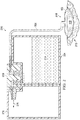
- FIG. 5 is a partial cross-sectional view of dressing connector 208 and canister 400 illustrating additional details that may be associated with some embodiments of reduced-pressure therapy system 100.
- Dressing connector 208 is shown engaged with canister 400 in Figure 5 , such that fittings 410-412 are inserted into receptacles 308-310, respectively.
- receptacles 308-310 and fittings 410-412 are tapered (chamfered) to guide the relative movement between receptacles 308-310 and fittings 410-412.
- Receptacles 308-310 may also provide recesses 502-504 adapted to engage and retain ridges 506-508 on fittings 410-412.
- recesses 502-504 and ridges 506-508 may be annular recesses and ridges.
- ridges 506-508 may be flexible pins or pegs. In some embodiments, only a single pin or peg may be preferable, while in other embodiments several pins or pegs may be annularly spaced (regularly or irregularly) about fittings 410-412. Additionally or alternatively, recesses 502-504 and ridges 506 may be configured to allow dressing connector 208 to engage canister 400 in only one orientation. Recesses 502-504 may be adapted to mate with ridges 506-508 accordingly. Fitting 322 may also provide a chamfered surface and a ridge 510 adapted to engage a receptacle 512, which may be associated with a conduit to or a housing of a reduced-pressure source or other downstream component, for example.
- dressing connector 208 and canister 400 provide fluid path 216 between an upstream component, such as a dressing, and receptacle 512.
- Fluid path 216 in this example can be generally described as having several parts.
- a lumen through tube 206 provides a fluid path between the upstream component and port 312, and channel 318 provides a fluid path between port 312 and receptacle 310.
- a channel 516 through fitting 412, a chamber 518 in canister 400, and a channel 520 through fitting 410 provide a fluid path between receptacle 310 and receptacle 308.
- Channel 316 and a channel 522 through fitting 322 provide a fluid path between receptacle 308 and an aperture 524 exposed on exterior surface 315.
- Liquid barrier 306 in this example can be disposed inline, i.e., in fluid path 216, between aperture 317 and aperture 320.
- the components of dressing connector 208 and canister 400 are preferably adapted to provide an airtight seal when coupled.
- fittings 410-412 and receptacles 308-310 may be sized to provide a press fit or an interference fit that substantially seals fluid path 216 from external environments.
- Figure 6 is a perspective view of an example embodiment of a reduced-pressure therapy system 600.
- This example embodiment illustrates a reduced-pressure source 602 adapted to mate with a canister 604 to provide a convenient system for applying reduced-pressure therapy.
- a fluid connection between reduced-pressure source 602 and canister 604 may be provided through a dressing connector 606.
- dressing connector 606 may be adapted to fit in a recess of reduced-pressure source 602 and canister 604 to minimize the profile of the assembly.
- Tubing 608 may similarly be adapted to fit in a recess of canister 604 to minimize the profile of the assembly, as well as provide additional stability of the fluid connection.
- FIG. 7 is a partial cross-sectional view of another example embodiment of a dressing connector, illustrated as dressing connector 702.
- Dressing connector 702 is illustrated engaged with a canister, such as canister 400.
- Dressing connector 702 may be similar to dressing connector 208 in many respects, but may also provide one or more feedback or sensing conduits, such as sensing conduit 704, which can fluidly connect a dressing to a controller or regulator, such as regulator 106.
- the controller or regulator regulate pressure in the dressing, and may also be adapted to detect improper connections, such as an inadequate connection between the dressing connector and the reduced-pressure source, or an inadequate seal between the drain port and the drain cover.
- dressing connector 702 can provide fluid path 216 between a downstream component and an upstream component, and also provides another fluid path 706.
- Fluid path 706 may include, for example, sensing conduit 704 fluidly coupled to a sensing lumen 708 in a multi-lumen tube 710, which can be coupled to a dressing or other upstream component.
- Fluid path 216 may include a delivery lumen 712 in multi-lumen tube 710 between the upstream component and port 312.
- Figures 8A-8B are partial cross-sectional views of yet other example embodiments of a dressing connector engaged with a canister.
- a dressing connector 802 is illustrated engaged with a canister, such as canister 400.
- Dressing connector 802 may be similar to dressing connector 208 and dressing connector 702 in many respects, but is illustrative of an alternative positioning of liquid barrier 804a-804b in fluid path 216.
- liquid barrier 804a-804b may be formed from a sintered polymer.
- Dressing connector 802 in this example may be a unitary structure, and liquid barrier 804a-804b may be welded or glued to port 302.
- an adhesive may be applied to an exterior surface of liquid barrier 804a, which may be inserted into port 322.
- an adhesive may be applied to an exterior surface and/or an interior surface of port 322 before receiving liquid barrier 804a.
- liquid barrier 804a may be coupled to port 322 with an interference fit.
- Adhesive may also be applied to an exterior surface of liquid barrier 804b and/or port 322 to secure liquid barrier 804b in position.
- liquid barriers 804a-804b may be disposed in fluid path 216, but may be disposed at least partially external to dressing connector 208, which may reduce part count and manufacturing complexity.
- a secondary inline filter may also be provided downstream of the dressing connector.
- a one-way control valve may be included to control the flow of exudates from the wound, which may be particularly advantageous while emptying the canister to prevent exudates in the tube and air from the surrounding environment from being drawn into the wound.
- a Vortis pump may additionally be integrated into the dressing connector, which can maintain reduced pressure after drawdown to significantly extend the life of the reduced-pressure therapy system.
- a drain plug or cover may be integrated with the dressing connector such that the dressing connector must be removed to empty fluid from the canister.
- the dressing connector may also provide a sacrificial fastener adapted to be broken or rendered inoperable in the process of either fitting the dressing connector to the canister or removing the dressing connector from the canister so that the dressing connector may not be re-used.
- reduced-pressure therapy system 100 provides a canister that can be re-used, which in turn can lead to significant reduction in cost and environmental impact over the duration of therapy.
- a canister may be manufactured through a low-cost process such as blow molding, substantially reducing errors in welding filters and potentially leading to yet additional cost savings.
- Reduced-pressure therapy system may also provide redundant liquid barriers, while promoting regular replacement of the primary liquid barrier without adding a mental burden to therapy.
Landscapes
- Health & Medical Sciences (AREA)
- Heart & Thoracic Surgery (AREA)
- Public Health (AREA)
- Engineering & Computer Science (AREA)
- Biomedical Technology (AREA)
- Veterinary Medicine (AREA)
- Life Sciences & Earth Sciences (AREA)
- Animal Behavior & Ethology (AREA)
- General Health & Medical Sciences (AREA)
- Vascular Medicine (AREA)
- Anesthesiology (AREA)
- Hematology (AREA)
- Otolaryngology (AREA)
- External Artificial Organs (AREA)
- Media Introduction/Drainage Providing Device (AREA)
Abstract
Description
- The present invention claims the benefit, under 35 USC § 119(e), of the filing of U.S. Provisional Patent Application serial number
61/700,217 - The present invention relates generally to tissue treatment systems and more particularly to systems and methods for collecting exudates in reduced-pressure therapy.
- Clinical studies and practice have shown that reducing pressure in proximity to a tissue site can augment and accelerate growth of new tissue at the tissue site. The applications of this phenomenon are numerous, but it has proven particularly advantageous for treating wounds. Regardless of the etiology of a wound, whether trauma, surgery, or another cause, proper care of the wound is important to the outcome. Treatment of wounds with reduced pressure may be commonly referred to as "reduced-pressure wound therapy," but is also known by other names, including "negative-pressure therapy," negative-pressure wound therapy," and "vacuum therapy," for example Reduced-pressure therapy may provide a number of benefits, including migration of epithelial and subcutaneous tissues, improved blood flow, and micro-deformation of tissue at a wound site. Together, these benefits can increase development of granulation tissue and reduce healing times.
- While the clinical benefits of reduced-pressure therapy are widely known, the cost and complexity of reduced-pressure therapy can be a limiting factor in its application, and the development and operation of reduced-pressure systems, components, and processes continues to present significant challenges to manufacturers, healthcare providers, and patients.
- In one example embodiment, a dressing connector is described herein that provides a first fluid path between a first connector and a second connector, and a second fluid path between a third connector and a fourth connector. A liquid barrier may be disposed in the first fluid path. The first fluid path and the second fluid path are generally exposed to an exterior surface of the dressing connector. In certain embodiments, the first connector may be a fitting, the second connector may be a receptacle, the third connector may be a port, and the fourth connector may be another receptacle. In some embodiments, a tube may also be bonded to the third connector to provide a third fluid path between the dressing connector and another component. In more particular embodiments, the liquid barrier may be a filter, such as a hydrophobic bacterial filter, a gel-blocking sintered polymer filter, and/or a charcoal filter.
- Alternatively, an example embodiment may provide a fitting fluidly coupled to a first receptacle through an inline liquid barrier, a port fluidly coupled to a second receptacle, and a tube fluidly coupled to the port. The fitting may be adapted to engage a downstream component, such as a reduced-pressure source. The first receptacle and the second receptacle each may provide a cavity exposed to an exterior surface adapted to engage a container fitting.
- A reduced-pressure treatment system is also described herein, wherein one example embodiment includes a downstream component, such as a reduced-pressure source, a reusable container, and a disposable dressing connector. The dressing connector may be coupled to the container and to an upstream component, such as a dressing. The dressing connector provides a first fluid path between the downstream component and the container, and a second fluid path between the container and the upstream component. A liquid barrier can be disposed in the first fluid path between the container and the downstream component. In some embodiments, a tube may couple the dressing connector to the downstream component, the upstream component, or both.
- A method of manufacturing a dressing component is also described herein, wherein one example embodiment includes forming a first interface comprising a first port, a second port, a first receptacle, and a second receptacle. A first channel may be formed from the first port to the first receptacle. A second channel may be formed from the second port to the second receptacle. A tube may be coupled to the first port, such as by bonding the tube to the first port with an adhesive. A second interface may be formed with a third port and a fitting. The second port and the third port may be aligned and a liquid barrier disposed between the second port and the third port before coupling the first interface to the second interface.
- A method of operating a reduced-pressure system to provide reduced-pressure therapy is also described. In one example method of providing reduced-pressure therapy, a dressing may be coupled to a first dressing connector. For example, a dressing may be applied to a tissue site and a tube may be coupled to the dressing and to the first dressing connector. The first dressing connector may then be coupled to a reusable fluid container, such as by pressing receptacles of the first dressing connector onto fittings of the fluid container. In some embodiments, orientation recesses of the first dressing connector may also be aligned with corresponding orientation fittings on the fluid container. The fluid container and the first dressing connector can then be coupled to a reduced-pressure source or other downstream component, such that a liquid barrier in the first dressing connector can be positioned between the fluid container and the reduced-pressure source. Reduced pressure can be applied to a tissue site through the dressing.
- Reduced-pressure may be applied and exudates collected from the tissue site in the fluid container. Exudates may be emptied from the fluid container and the first dressing connector may be replaced with a second dressing connector having a second (and preferably unused) liquid barrier. The first dressing connector can be disposed of with the dressing, which encourages regular changes of liquid barriers.
- Other objects, features, and advantages of the embodiments described herein will become apparent with reference to the drawings and detailed description that follow.
-
-
Figures 1A-1B are functional block diagrams of example embodiments of a reduced-pressure therapy system that can collect exudates in accordance with this specification; -
Figure 2 is a schematic diagram illustrating additional details that may be associated with an example embodiment of the reduced-pressure therapy system; -
Figure 3 is an exploded diagram illustrating additional details that may be associated with an example embodiment of a dressing connector that may be associated with the reduced-pressure therapy system; -
Figure 4 is perspective view of a container that may be associated with example embodiments of the reduced-pressure therapy system; -
Figure 5 is a partial cross-sectional view of the dressing connector ofFigure 3 and the container ofFigure 4 illustrating additional details that may be associated with some embodiments of the reduced-pressure therapy system; -
Figure 6 is a perspective view of another example embodiment of a reduced-pressure therapy system; -
Figure 7 is a partial cross-sectional view of another example embodiment of a dressing connector that may be associated with the reduced-pressure therapy system; and -
Figures 8A-8B are partial cross-sectional views of yet other example embodiments of a dressing connector engaged with a canister that may be associated with the reduced-pressure therapy system. - New and useful systems and methods for collecting exudates in a reduced-pressure therapy environment are set forth in the appended claims. Objectives, advantages, and a preferred mode of making and using the systems and methods may be understood best by reference to the following detailed description in conjunction with the accompanying drawings. The description provides information that enables a person skilled in the art to make and use the claimed subject matter, but may omit certain details already well-known in the art. Moreover, descriptions of various alternatives using terms such as "or" do not necessarily require mutual exclusivity unless clearly required by the context. The claimed subject matter may also encompass alternative embodiments not specifically described in detail. The following detailed description is, therefore, to be taken as illustrative and not limiting.
- The example embodiments may also be described herein with reference to spatial relationships between various elements or to the spatial orientation of various elements depicted in the attached drawings. In general, such relationships or orientation assume a frame of reference consistent with or relative to a patient in a position to receive treatment. However, as should be recognized by those skilled in the art, this frame of reference is merely a descriptive expedient rather than a strict prescription.
-
Figures 1A-1B are simplified functional block diagrams of example embodiments of a reduced-pressure therapy system 100 that can collect exudates in accordance with this specification. As illustrated, reduced-pressure therapy system 100 may include adressing 102 fluidly coupled to a reduced-pressure source 104. A regulator or controller, such asregulator 106, may also be fluidly coupled to dressing 102 and reduced-pressure source 104. Dressing 102 generally includes a drape, such asdrape 108, and a manifold, such aspressure distribution manifold 110. Reduced-pressure therapy system 100 may also include fluid container, such ascontainer 112, coupled to dressing 102 and reduced-pressure source 104. - In general, components of reduced-
pressure therapy system 100 may be coupled directly or indirectly. For example, reduced-pressure source 104 may be directly coupled toregulator 106 and indirectly coupled to dressing 102 throughregulator 106. Components may be fluidly coupled to each other to provide a path for transferring fluids (i.e., liquid and/or gas) between the components. In some embodiments, components may be fluidly coupled with a tube, for example. A "tube," as used herein, broadly refers to a tube, pipe, hose, conduit, or other structure with one or more lumina adapted to convey fluids between two ends. Typically, a tube is an elongated, cylindrical structure with some flexibility, but the geometry and rigidity may vary. In some embodiments, components may additionally or alternatively be coupled by virtue of physical proximity, being integral to a single structure, or being formed from the same piece of material. Coupling may also include mechanical, thermal, electrical, or chemical coupling (such as a chemical bond) in some contexts. - In operation,
pressure distribution manifold 110 may be placed within, over, on, or otherwise proximate to a tissue site.Drape 108 may be placed overpressure distribution manifold 110 and sealed to tissue proximate the tissue site. The tissue proximate to the tissue site is often undamaged epidermis peripheral to the tissue site. Thus, dressing 102 can provide a sealed therapeutic environment proximate to a tissue site, substantially isolated from the external environment, and reduced-pressure source 104 can reduce the pressure in the sealed therapeutic environment. Reduced pressure applied uniformly throughpressure distribution manifold 110 in the sealed therapeutic environment can induce macrostrain and microstrain in the tissue site, as well as remove exudates and other fluids from the tissue site, which can be collected incontainer 112 and disposed of properly. - The fluid mechanics of using a reduced-pressure source to reduce pressure in another component or location, such as within a sealed therapeutic environment, can be mathematically complex. However, the basic principles of fluid mechanics applicable to reduced-pressure therapy are generally well-known to those skilled in the art, and the process of reducing pressure may be described illustratively herein as "delivering," "distributing," or "generating" reduced pressure, for example.
- In general, exudates and other fluids flow toward lower pressure along a fluid path. This orientation is generally presumed for purposes of describing various features and components of reduced-pressure therapy systems herein. Thus, the term "downstream" typically implies something in a fluid path relatively closer to a reduced-pressure source, and conversely, the term "upstream" implies something relatively further away from a reduced-pressure source. Similarly, it may be convenient to describe certain features in terms of fluid "inlet" or "outlet" in such a frame of reference. However, the fluid path may also be reversed in some applications (such as by substituting a positive-pressure source for a reduced-pressure source) and this descriptive convention should not be construed as a limiting convention.
- The term "tissue site" in this context broadly refers to a wound or defect located on or within tissue, including but not limited to, bone tissue, adipose tissue, muscle tissue, neural tissue, dermal tissue, vascular tissue, connective tissue, cartilage, tendons, or ligaments. A wound may include chronic, acute, traumatic, subacute, and dehisced wounds, partial-thickness bums, ulcers (such as diabetic, pressure, or venous insufficiency ulcers), flaps, and grafts, for example. The term "tissue site" may also refer to areas of any tissue that are not necessarily wounded or defective, but are instead areas in which it may be desirable to add or promote the growth of additional tissue. For example, reduced pressure may be used in certain tissue areas to grow additional tissue that may be harvested and transplanted to another tissue location.
- "Reduced pressure" generally refers to a pressure less than a local ambient pressure, such as the ambient pressure in a local environment external to a sealed therapeutic environment provided by dressing 102. In many cases, the local ambient pressure may also be the atmospheric pressure at which a patient is located. Alternatively, the pressure may be less than a hydrostatic pressure associated with tissue at the tissue site. Unless otherwise indicated, values of pressure stated herein are gauge pressures. Similarly, references to increases in reduced pressure typically refer to a decrease in absolute pressure, while decreases in reduced pressure typically refer to an increase in absolute pressure.
- A reduced-pressure source, such as reduced-
pressure source 104, may be a reservoir of air at a reduced pressure, or may be a manual or electrically-powered device that can reduced the pressure in a sealed volume, such as a vacuum pump, a suction pump, a wall suction port available at many healthcare facilities, or a micro-pump, for example. The reduced-pressure source may be housed within or used in conjunction with other components, such as sensors, processing units, alarm indicators, memory, databases, software, display devices, or user interfaces that further facilitate reduced-pressure therapy. While the amount and nature of reduced pressure applied to a tissue site may vary according to therapeutic requirements, the pressure typically ranges between -5 mm Hg (-667 Pa) and -500 mm Hg (-66.7 kPa). Common therapeutic ranges are between -75 mm Hg (-9.9 kPa) and -300 mm Hg (-39.9 kPa). -
Pressure distribution manifold 110 can be generally adapted to contact a tissue site.Pressure distribution manifold 110 may be partially or fully in contact with the tissue site. If the tissue site is a wound, for example,pressure distribution manifold 110 may partially or completely fill the wound, or may be placed over the wound.Pressure distribution manifold 110 may take many forms, and may have many sizes, shapes, or thicknesses depending on a variety of factors, such as the type of treatment being implemented or the nature and size of a tissue site. For example, the size and shape ofpressure distribution manifold 110 may be adapted to the contours of deep and irregular shaped tissue sites. - More generally, a manifold is a substance or structure adapted to distribute reduced pressure to and/or remove fluids from a tissue site, or both. In some embodiments, though, a manifold may also facilitate delivering fluids to a tissue site, if the fluid path is reversed or a secondary fluid path is provided, for example. A manifold may include flow channels or pathways that distribute fluids provided to and removed from a tissue site around the manifold. In one illustrative embodiment, the flow channels or pathways may be interconnected to improve distribution of fluids provided to or removed from a tissue site. For example, cellular foam, open-cell foam, porous tissue collections, and other porous material such as gauze or felted mat generally include structural elements arranged to form flow channels. Liquids, gels, and other foams may also include or be cured to include flow channels.
- In one illustrative embodiment,
pressure distribution manifold 110 may be a porous foam material having interconnected cells or pores adapted to uniformly (or quasi-uniformly) distribute reduced pressure to a tissue site. The foam material may be either hydrophobic or hydrophilic. In one non-limiting example,pressure distribution manifold 110 can be an open-cell, reticulated polyurethane foam such as GranuFoam® dressing available from Kinetic Concepts, Inc. of San Antonio, Texas. - In an example in which pressure
distribution manifold 110 may be made from a hydrophilic material,pressure distribution manifold 110 may also wick fluid away from a tissue site, while continuing to distribute reduced pressure to the tissue site. The wicking properties ofpressure distribution manifold 110 may draw fluid away from a tissue site by capillary flow or other wicking mechanisms. An example of a hydrophilic foam is a polyvinyl alcohol, open-cell foam such as V.A.C. WhiteFoam® dressing available from Kinetic Concepts, Inc. of San Antonio, Texas. Other hydrophilic foams may include those made from polyether. Other foams that may exhibit hydrophilic characteristics include hydrophobic foams that have been treated or coated to provide hydrophilicity. -
Pressure distribution manifold 110 may further promote granulation at a tissue site when pressure within the sealed therapeutic environment is reduced. For example, any or all of the surfaces ofpressure distribution manifold 110 may have an uneven, coarse, or jagged profile that can induce microstrains and stresses at a tissue site if reduced pressure is applied throughpressure distribution manifold 110. - In one embodiment,
pressure distribution manifold 110 may be constructed from bioresorbable materials. Suitable bioresorbable materials may include, without limitation, a polymeric blend of polylactic acid (PLA) and polyglycolic acid (PGA). The polymeric blend may also include without limitation polycarbonates, polyfumarates, and capralactones.Pressure distribution manifold 110 may further serve as a scaffold for new cell-growth, or a scaffold material may be used in conjunction withpressure distribution manifold 110 to promote cell-growth. A scaffold is generally a substance or structure used to enhance or promote the growth of cells or formation of tissue, such as a three-dimensional porous structure that provides a template for cell growth. Illustrative examples of scaffold materials include calcium phosphate, collagen, PLA/PGA, coral hydroxy apatites, carbonates, or processed allograft materials. -
Drape 108 is an example of a sealing member. A sealing member may be constructed from a material that can provide a fluid seal between two components or two environments, such as between a therapeutic environment and a local external environment. The sealing member may be, for example, an impermeable or semi-permeable, elastomeric material that can provide a seal adequate to maintain a reduced pressure at a tissue site for a given reduced-pressure source. For semi-permeable materials, the permeability generally should be low enough that a desired reduced pressure may be maintained. An attachment device may be used to attach a sealing member to an attachment surface, such as undamaged epidermis, a gasket, or another sealing member. The attachment device may take many forms. For example, an attachment device may be a medically-acceptable, pressure-sensitive adhesive that extends about a periphery, a portion, or an entire sealing member. Other example embodiments of an attachment device may include a double-sided tape, paste, hydrocolloid, hydrogel, silicone gel, organogel, or an acrylic adhesive. -
Container 112 is representative of a container, canister, pouch, or other storage component that can be used to manage exudates and other fluids withdrawn from a tissue site. In many environments, a rigid container may be preferred or required for collecting, storing, and disposing of fluids. In other environments, fluids may be properly disposed of without rigid container storage, and a re-usable container could reduce waste and costs associated with reduced-pressure therapy. Liquid barriers are usually an integral part of most reduced-pressure therapy containers, though. For example, certain filters can reduce odor and prevent exudates from entering the reduced-pressure source and other components downstream from the container. In general, liquid barriers allow air to flow from the container to the reduced-pressure source while preventing contamination. However, protein deposits can accumulate on the liquid barriers and gradually reduce the volume of air flowing from the container, which can adversely affect therapy and cause false blockage alarms. Consequently, filters can be a limiting factor for re-using a container. - As disclosed herein, reduced-
pressure therapy system 100 can overcome these shortcomings and others by providing a re-usable container for collecting exudates that ensures filter changes at regular intervals. For example, in some embodiments of reduced-pressure therapy system 100,container 112 may be a re-usable fluid container, and a single- use dressing connector, such asconnector 114, may couplecontainer 112 to dressing 102 and reduced-pressure source 104. In one particular embodiment, the dressing connector includes an integrated, inline liquid barrier and provides two pneumatic pathways. In general, the first pneumatic pathway can connect the dressing to the fluid container, and the second pneumatic pathway can connect the fluid container to the reduced-pressure source or other downstream components, through the liquid barrier. The dressing connector may also include a tube having one end bonded or semi-permanently coupled to the first pneumatic pathway. The other end of the tube can be connected to the dressing during therapy. In some embodiments, the second pneumatic pathway may be directly coupled to a reduced-pressure source through a port adapted for mating with the reduced-pressure source, while in other embodiments the second pneumatic pathway may be indirectly coupled to a reduced-pressure source through one or more intermediate components. The fluid container may also include a drain port with a drain cover that may be removed and replaced. The fluid container may be a rigid canister in some embodiments, but may be a flexible container such as a soft-sided pouch in other embodiments. - In general, reduced-pressure therapy may be applied until a dressing requires replacement or therapy is complete. When the dressing requires replacement or therapy is complete, the fluid container may be emptied and the dressing connector (with the integrated liquid barrier) can be disposed of with the dressing. Consequently, the liquid barrier may only be used for a fixed duration or for a fixed volume of exudates, which substantially reduces or eliminates cross-contamination between patients (as a dressing should not be used on multiple patients) and blockages due to extended use by a single patient.
-
Figure 2 is a schematic diagram illustrating additional details that may be associated with an example embodiment of reduced-pressure therapy system 100. In this example embodiment, reduced-pressure therapy system 100 generally includes a dressing 202 fluidly coupled to a container, such ascanister 204, through atube 206 anddressing connector 208. In some embodiments, a dressing interface (not shown) may facilitate coupling dressing 202 andtube 206. For example, such a dressing interface may be a T.R.A.C.® Pad or Sensa T.R.A.C.® Pad available from KCI of San Antonio, Texas. In some embodiments, the dressing interface may be a portion oftube 206 extending into the sealed therapeutic environment, or may be a vacuum port on a micro-pump that extends into the sealed therapeutic environment. -
Dressing connector 208 in this example embodiment can be directly coupled to a reduced-pressure source 210. Thus,canister 204 can be fluidly coupled to both dressing 202 and reduced-pressure source 210.Canister 204 and reduced-pressure source 210 may additionally be mechanically coupled to increase stability, such as with a fastener or interlocking features. As illustrated inFigure 2 , dressing 202 may be applied to atissue site 212, andexudates 214 may be removed from thetissue site 212 and collected incanister 204 as reduced-pressure therapy is applied. In general, exudates and other fluids flow toward lower pressure along afluid path 216. -
Figure 3 is an exploded diagram illustrating additional details that may be associated with an example embodiment of dressingconnector 208. In this example embodiment, dressingconnector 208 generally includes interfaces 302-304 and aliquid barrier 306.Interface 302 may be generally described as a "container interface" that provides connectors, fasteners, or fittings adapted to mate with corresponding connectors, fasteners, or fittings of another component, particularly a fluid container. InFigure 3 , for example,interface 302 is illustrated with three female connectors, i.e., receptacles 308-310 and aport 312, but other combinations of male and female connectors are also possible.Interface 302 may additionally provide one or more orientation guides, such asorientation recesses 314a-314b. Receptacles 308-310,port 312, andorientation recesses 314a-314b are generally exposed to anexterior surface 315 of dressingconnector 208. For example, in the example embodiment ofFigure 3 , receptacles 308-310 are exposed on a first side ofexterior surface 315 andport 312 is exposed on a second, adjacent side. - In more particular embodiments, receptacles 308-310 may be generally described as cavities exposed to
exterior surface 315 and adapted to receive and hold a male connector. In yet more particular embodiments,receptacle 308 may be an inlet receptacle adapted to receive fluid flow from an outlet fitting of a container, andreceptacle 310 may be an outlet receptacle adapted to exhaust fluid flow into the container. Achannel 316 may fluidly couple receptacle 308 to anaperture 317, and achannel 318 may fluidly couple receptacle 310 toport 312.Tube 206 may be bonded or semi-permanently attached toport 312 to prevent separation under expected therapeutic conditions. For example,tube 206 may be bonded toport 312 with an adhesive, glue, or cement, ortube 206 andport 312 may be sized to provide a press fit. -
Interface 304 may be generally described as a "downstream interface" that provides anaperture 320 adapted for fluid communication withchannel 316 and a connector adapted to engage a downstream component. InFigure 3 , for example, the connector is represented as a fitting 322 that may be adapted to mechanically couple with reduced-pressure source 210. In the illustrated embodiment, fitting 322 is a male fitting (i.e., a part bearing one or more protrusions) adapted to engage a female fitting or receptacle, but in other embodiments, fitting 322 may be a female fitting adapted to engage a male fitting, for example.Interface 304 may additionally include arecess 324 adapted to receiveliquid barrier 306. - In this example embodiment,
tube 206 can be fluidly coupled to port 312 (i.e., through a lumen in tube 206) andport 312 can be fluidly coupled to receptacle 310 (i.e., through channel 318). When assembled,aperture 320 may be aligned withaperture 317 to fluidly couple fitting 322 to receptacle 316 throughliquid barrier 306. - In more particular embodiments,
liquid barrier 306 may be a hydrophobic, bacterial filter. A charcoal filter may also be co-located or placed inline with the hydrophobic, bacterial filter to reduce odor. In yet more particular embodiments,liquid barrier 306 may be a gel-blocking sintered polymer filter that swells on contact with water, which can block the fluid path between a reduced-pressure source and a canister. Suitable polymers include, for example, fluoropolymers such as polytetrafluoroethylene (PTFE), polyvinylidene fluoride (PVdF), or fluorinated ethylenepropylene (FEP); chlorofluoropolymers, such as polychlorotrifluoroethylene (PCTFE); polyolefins such as high density polyethylene (HDPE), polypropylene (PP), cyclic olefin copolymer (COC), or polymethylpent-1-ene (PMP); polyvinyl acetate (PVAc) or ethylene vinyl acetate (EVA); polycarbonate (PC); polyesters such as polyethylene terephthalate (PET) or PET copolymers (PETG); or polysulphones or polyethersulphones. The polymer may also contain charcoal to reduce odor. Additionally, filters may be coated to enhance hydrophobicity in some embodiments. Polymers may be formed into membranes or sintered (particularly for PVAc, EVA, polyolefin's, and fluoropolymers). - In the example embodiment of
Figure 3 ,interface 302 andinterface 304 are illustrated as separate components that may be bonded together to encloseliquid barrier 306. In other embodiments, dressingconnector 208 may be fabricated from a single mold in which interface 302 andinterface 304 form a unitary structure.Liquid barrier 306 in this instance may be formed from a sintered polymer, for example, that can be inserted intoport 322 of the unitary structure consisting of 302 and 304. This type of assembly may also suit a more common sheet filter welded or glued to a molded carrier that can also be pushed intoport 322.Liquid barrier 306 may also be welded or glued directly to a singular unitary structure consisting of 302 and 304. - In an example embodiment of manufacturing a dressing connector such as
dressing connector 208, a first interface (such as interface 302) may be formed with a first port (such as port 312), a second port, a first receptacle (such as receptacle 310), and a second receptacle (such as receptacle 308). A first channel, such aschannel 318, may be formed from the first port to the first receptacle. A second channel, such aschannel 316, may be formed from the second port to the second receptacle. A tube such astube 206 may be coupled to the first port, such as by bonding the tube to the first port with an adhesive. A second interface (such as interface 304) may be formed with a third port (such as aperture 320) and a fitting (such as fitting 322). The second port and the third port may be aligned and a liquid barrier disposed between the second port and the third port before coupling the first interface to the second interface. -
Figure 4 is a perspective view of a container that may be associated with example embodiments of reduced-pressure therapy system 100. In this example embodiment, the container may be arigid canister 400 that generally includes aninterface 402, analignment recess 404, adrain port 406, and adrain cover 408.Interface 402 may be described as a "connector interface" that can be recessed in thebody 414 ofrigid canister 400 and adapted for fluidly coupling with a dressing connector, such asinterface 302 of dressingconnector 208. For example,interface 402 may provide fittings 410-412, which can be adapted for coupling to receptacles 308-310, and may be dimensioned and recessed withinbody 414 ofcanister 400 to minimize the profile of dressingconnector 208. Similarly,alignment recess 404 may be dimensioned to receivetube 206 to minimize the profile oftube 206. More particularly, in one embodiment,alignment recess 404 may have a depth that is substantially equivalent to an outside diameter of a longitudinal portion oftube 206. In some embodiments,rigid canister 400 may additionally include orientation fittings (not shown) adapted to mate withorientation recesses 314a-314b to facilitate proper orientation of dressingconnector 208. In more particular embodiments, fitting 410 may be an outlet fitting adapted to sealingly engage and exhaust fluid flow to an inlet receptacle of a dressing connector, and fitting 412 may be an inlet fitting adapted to sealingly engage and receive fluid flow from a dressing connector, such asdressing connector 208. In the particular example embodiment illustrated inFigure 4 ,canister 400 also provides a shoulder 416, a ridge 418 fixed to shoulder 416, and an end surface 418. Shoulder 416 and ridge 418 are adapted to abut a counterpart ridge and shoulder, respectively, on another component, such as a reduced-pressure source. Thus, shoulder 416 and ridge 418 can be used as a structural support for coupling to other components, as well as providing clearance fordrain port 406 anddrain cover 408 positioned on end surface 418, as shown inFigure 4 . - In one example method of providing reduced-pressure therapy, a dressing may be coupled to a first dressing connector. For example, a dressing may be applied to a tissue site and
tube 206 may be coupled to the dressing and to dressingconnector 208.Dressing connector 208 may then be coupled tocanister 400, such as by pressing receptacles 308-310 onto fittings 410-412, respectively. In some embodiments,orientation recesses 314a-314b may also be aligned with corresponding orientation fittings oncanister 400.Canister 400 anddressing connector 208 can then be coupled to reduced-pressure source 210, such thatliquid barrier 306 is disposed in the fluid path betweencanister 400 and reduced-pressure source 210.Tube 206 may be placed inalignment recess 404, and therapy may be initiated (reduced-pressure source 210 may be activated and reduced pressure applied through the dressing, for example). In some embodiments, reduced-pressure therapy system 100 may include a leak detector and can be programmed to activate an alarm or alert ifdrain cover 408 is not replaced properly or if dressingconnector 208 is not properly coupled to reduced-pressure source 210. - Reduced-pressure may be applied and exudates collected from the tissue site in
canister 400 untilcanister 400 is substantially full, the dressing needs changing, or therapy is complete, for example. Exudates may be emptied fromcanister 400, and dressingconnector 208 may be replaced with a second dressing connector having a second (and preferably unused) liquid barrier. For example, the dressing may be removed from the tissue site, and dressingconnector 208 may be removed fromcanister 400. A second dressing can be coupled to the second dressing connector, which can be coupled tocanister 400 and reduced-pressure source 210. Dressing connector 208 (with liquid barrier 306) can (and should) be disposed of with the dressing, which encourages regular changes ofliquid barrier 306. - These operations are merely illustrative, however, and some of these operations may be consolidated or omitted, where appropriate, and these operations may be modified or changed considerably without departing from the scope of teachings provided herein. In addition, a number of these operations may be executed concurrently with, or in parallel to, one or more additional operations. The sequence of these operations may be altered considerably, as reduced-
pressure therapy system 100 provides substantial flexibility. -
Figure 5 is a partial cross-sectional view ofdressing connector 208 andcanister 400 illustrating additional details that may be associated with some embodiments of reduced-pressure therapy system 100.Dressing connector 208 is shown engaged withcanister 400 inFigure 5 , such that fittings 410-412 are inserted into receptacles 308-310, respectively. In the example embodiment ofFigure 5 , receptacles 308-310 and fittings 410-412 are tapered (chamfered) to guide the relative movement between receptacles 308-310 and fittings 410-412. Receptacles 308-310 may also provide recesses 502-504 adapted to engage and retain ridges 506-508 on fittings 410-412. In some embodiments, recesses 502-504 and ridges 506-508 may be annular recesses and ridges. In other example embodiments, ridges 506-508 may be flexible pins or pegs. In some embodiments, only a single pin or peg may be preferable, while in other embodiments several pins or pegs may be annularly spaced (regularly or irregularly) about fittings 410-412. Additionally or alternatively, recesses 502-504 andridges 506 may be configured to allow dressingconnector 208 to engagecanister 400 in only one orientation. Recesses 502-504 may be adapted to mate with ridges 506-508 accordingly. Fitting 322 may also provide a chamfered surface and aridge 510 adapted to engage areceptacle 512, which may be associated with a conduit to or a housing of a reduced-pressure source or other downstream component, for example. - When engaged, as illustrated in the example embodiments of
Figure 5 , dressingconnector 208 andcanister 400 providefluid path 216 between an upstream component, such as a dressing, andreceptacle 512.Fluid path 216 in this example can be generally described as having several parts. For example, a lumen throughtube 206 provides a fluid path between the upstream component andport 312, andchannel 318 provides a fluid path betweenport 312 andreceptacle 310. Achannel 516 through fitting 412, achamber 518 incanister 400, and achannel 520 through fitting 410 provide a fluid path betweenreceptacle 310 andreceptacle 308.Channel 316 and achannel 522 through fitting 322 provide a fluid path betweenreceptacle 308 and anaperture 524 exposed onexterior surface 315.Liquid barrier 306 in this example can be disposed inline, i.e., influid path 216, betweenaperture 317 andaperture 320. The components of dressingconnector 208 andcanister 400 are preferably adapted to provide an airtight seal when coupled. For example, fittings 410-412 and receptacles 308-310 may be sized to provide a press fit or an interference fit that substantially sealsfluid path 216 from external environments. -
Figure 6 is a perspective view of an example embodiment of a reduced-pressure therapy system 600. This example embodiment illustrates a reduced-pressure source 602 adapted to mate with acanister 604 to provide a convenient system for applying reduced-pressure therapy. A fluid connection between reduced-pressure source 602 andcanister 604 may be provided through adressing connector 606. Moreover, dressingconnector 606 may be adapted to fit in a recess of reduced-pressure source 602 andcanister 604 to minimize the profile of the assembly.Tubing 608 may similarly be adapted to fit in a recess ofcanister 604 to minimize the profile of the assembly, as well as provide additional stability of the fluid connection. -
Figure 7 is a partial cross-sectional view of another example embodiment of a dressing connector, illustrated as dressingconnector 702.Dressing connector 702 is illustrated engaged with a canister, such ascanister 400.Dressing connector 702 may be similar to dressingconnector 208 in many respects, but may also provide one or more feedback or sensing conduits, such assensing conduit 704, which can fluidly connect a dressing to a controller or regulator, such asregulator 106. The controller or regulator regulate pressure in the dressing, and may also be adapted to detect improper connections, such as an inadequate connection between the dressing connector and the reduced-pressure source, or an inadequate seal between the drain port and the drain cover. As illustrated, dressingconnector 702 can providefluid path 216 between a downstream component and an upstream component, and also provides anotherfluid path 706.Fluid path 706 may include, for example, sensingconduit 704 fluidly coupled to asensing lumen 708 in amulti-lumen tube 710, which can be coupled to a dressing or other upstream component.Fluid path 216 may include adelivery lumen 712 inmulti-lumen tube 710 between the upstream component andport 312. -
Figures 8A-8B are partial cross-sectional views of yet other example embodiments of a dressing connector engaged with a canister. In these examples, adressing connector 802 is illustrated engaged with a canister, such ascanister 400.Dressing connector 802 may be similar to dressingconnector 208 anddressing connector 702 in many respects, but is illustrative of an alternative positioning ofliquid barrier 804a-804b influid path 216. In some embodiments,liquid barrier 804a-804b may be formed from a sintered polymer.Dressing connector 802 in this example may be a unitary structure, andliquid barrier 804a-804b may be welded or glued toport 302. For example, an adhesive may be applied to an exterior surface ofliquid barrier 804a, which may be inserted intoport 322. Alternatively or additionally, an adhesive may be applied to an exterior surface and/or an interior surface ofport 322 before receivingliquid barrier 804a. In other embodiments,liquid barrier 804a may be coupled toport 322 with an interference fit. Adhesive may also be applied to an exterior surface ofliquid barrier 804b and/orport 322 to secureliquid barrier 804b in position. Thus,liquid barriers 804a-804b may be disposed influid path 216, but may be disposed at least partially external to dressingconnector 208, which may reduce part count and manufacturing complexity. - Yet other components may be provided in alternative or additional embodiments. For example, a secondary inline filter may also be provided downstream of the dressing connector. A one-way control valve may be included to control the flow of exudates from the wound, which may be particularly advantageous while emptying the canister to prevent exudates in the tube and air from the surrounding environment from being drawn into the wound. A Vortis pump may additionally be integrated into the dressing connector, which can maintain reduced pressure after drawdown to significantly extend the life of the reduced-pressure therapy system.
- In another example embodiment, a drain plug or cover may be integrated with the dressing connector such that the dressing connector must be removed to empty fluid from the canister. The dressing connector may also provide a sacrificial fastener adapted to be broken or rendered inoperable in the process of either fitting the dressing connector to the canister or removing the dressing connector from the canister so that the dressing connector may not be re-used.
- The systems and methods described herein may provide significant advantages, some of which have already been mentioned. For example, reduced-
pressure therapy system 100 provides a canister that can be re-used, which in turn can lead to significant reduction in cost and environmental impact over the duration of therapy. Moreover, such a canister may be manufactured through a low-cost process such as blow molding, substantially reducing errors in welding filters and potentially leading to yet additional cost savings. Reduced-pressure therapy system may also provide redundant liquid barriers, while promoting regular replacement of the primary liquid barrier without adding a mental burden to therapy. - It should be apparent from the foregoing that an invention having significant advantages has been provided. While shown in only a few forms, the systems and methods illustrated are susceptible to various changes and modifications without departing from the spirit thereof.
- Aspects of the invention are disclosed in the following numbered clauses:
- 1. A dressing connector, comprising:
- a first fluid path between a first connector and a second connector;
- a liquid barrier disposed in the first fluid path; and
- a second fluid path between a third connector and a fourth connector;
- wherein the first fluid path and the second fluid path are exposed to an exterior surface of the dressing connector.
- 2. The dressing connector of clause 1, wherein:
- the first connector is a fitting;
- the second connector is a first receptacle;
- the third connector is a port; and
- the fourth connector is a second receptacle.
- 3. The dressing connector of any preceding clause, further comprising a tube bonded to the third connector.
- 4. The dressing connector of clause 3, wherein the tube comprises a delivery lumen and a sensing lumen, and further comprising a third fluid path adapted for fluidly coupling with the sensing lumen.
- 5. The dressing connector of any preceding clause, wherein the liquid barrier is a filter.
- 6. The dressing connector of any preceding clause, wherein the liquid barrier comprises a hydrophobic bacterial filter.
- 7. The dressing connector of any preceding clause, wherein the liquid barrier comprises a gel-blocking sintered polymer filter.
- 8. The dressing connector of any preceding clause, wherein the liquid barrier comprises a charcoal filter.
- 9. The dressing connector of any preceding clause, wherein the first connector is a tapered fitting.
- 10. The dressing connector of any preceding clause, wherein the second connector and the fourth connector each comprises a cavity exposed to the exterior surface.
- 11. The dressing connector of any preceding clause, wherein the second connector and the fourth connector each comprises a tapered cavity exposed to the exterior surface.
- 12. The dressing connector of any preceding clause, wherein the second connector and the fourth connector each comprises a recess within a cavity adapted to engage a ridge on a container fitting.
- 13. The dressing connector of any preceding clause, wherein the second connector and the fourth connector each comprises an annular recess adapted to engage a ridge on a container fitting.
- 14. The dressing connector of any preceding clause, wherein the first fluid path comprises a channel through the first connector and a port exposing the channel to the exterior surface.
- 15. The dressing connector of any preceding clause, wherein the first connector comprises a ridge adapted to engage a downstream component.
- 16. The dressing connector of any preceding clause, further comprising an orientation recess adjacent to the second connector and the fourth connector.
- 17. The dressing connector of any preceding clause, further comprising a one-way valve in the second fluid path.
- 18. The dressing connector of any preceding clause, wherein the liquid barrier is disposed at least partially external to the first connector.
- 19. A dressing connector, comprising:
- a fitting fluidly coupled to a first receptacle through an inline liquid barrier;
- a port fluidly coupled to a second receptacle; and
- a tube fluidly coupled to the port;
- wherein the fitting is adapted to engage a downstream component, and the first receptacle and the second receptacle each comprises a cavity exposed to an exterior surface adapted to engage a container fitting.
- 20. The dressing connector of clause 19, wherein:
- the fitting comprises a male fitting and an annular ridge adapted to engage the downstream component; and
- each cavity comprises an annular recess adapted to engage the container fitting.
- 21. A reduced-pressure treatment system comprising:
- a downstream component;
- a container;
- a tube coupled to an upstream component; and
- a dressing connector coupled to the container and to the tube;
- wherein the dressing connector comprises a first fluid path between the container and the downstream component, a second fluid path between the container and the tube, and a liquid barrier disposed in the first fluid path.
- 22. The reduced-pressure system of clause 21, wherein:
- the container comprises a connector interface;
- the dressing connector comprises a container interface; and
- the container interface is fluidly coupled to the connector interface.
- 23. The reduced-pressure system of clause 21, wherein:
- the container comprises two fittings;
- the dressing connector comprises two receptacles; and
- the two receptacles are fluidly coupled to the two fittings.
- 24. The reduced-pressure system of clause 21 or any of clauses 22-23, wherein the downstream component is a reduced-pressure source.
- 25. The reduced-pressure system of clause 21 or any of clauses 22-24, wherein the downstream component is a vacuum pump.
- 26. The reduced-pressure system of clause 21 or any of clauses 22-25, wherein the upstream component is a manifold.
- 27. The reduced-pressure system of clause 21 or any of clauses 22-26, wherein the container is a rigid canister comprising a drain port and an alignment recess adapted to receive a longitudinal portion of the tube.
- 28. The reduced-pressure system of clause 21, wherein:
- the downstream component is a reduced-pressure source;
- the upstream component is a manifold;
- the container is a rigid canister comprising a drain port, an alignment recess adapted to receive a longitudinal portion of the tube, and two fittings;
- the dressing connector comprises two receptacles; and
- the two receptacles are fluidly coupled to the two fittings.
- 29. The reduced-pressure system of clause 21 or any of clauses 22-28, wherein:
- the tube comprises a delivery lumen and a sensing lumen;
- the dressing connector further comprises a third fluid path;
- the second fluid path is in fluid communication with the delivery lumen; and
- the third fluid path is in fluid communication with the sensing lumen.
- 30. A system for collecting exudates in a reduced-pressure therapy environment, the system comprising:
- a dressing connector comprising:
- a first interface adapted to couple the dressing connector to a downstream component,
- a second interface,
- a tube,
- a first fluid path between the first interface and the second interface,
- a second fluid path between the second interface and the tube, and
- a liquid barrier in the first fluid path; and
- a container comprising:
- a fluid chamber;
- a third interface fluidly coupled to the fluid chamber,
- an alignment recess on an external surface, and
- a drain port fluidly coupled to the fluid chamber;
- wherein the second interface is adapted to couple to the third interface and fluidly couple the first fluid path to the second fluid path through the fluid chamber.
- a dressing connector comprising:
- 31. The system of clause 30, wherein:
- the second interface comprises an inlet receptacle and an outlet receptacle;
- the third interface comprises an inlet fitting and an outlet fitting;
- the inlet fitting is adapted to sealingly engage the outlet receptacle; and
- the outlet fitting is adapted to sealingly engage the inlet receptacle.
- 32. The system of clause 31, wherein:
- the inlet fitting comprises an inlet channel fluidly coupled to the fluid chamber; and
- the outlet fitting comprises an outlet channel fluidly coupled to the fluid chamber;
- whereby the first fluid path can be fluidly coupled to the second fluid path through the inlet channel and the outlet channel.
- 33. The system of clause 31 or clause 32, wherein:
- first interface comprises a fitting;
- the first fluid path comprises a fluid channel through the fitting; and
- the liquid barrier is in the first fluid path between the inlet receptacle and the fluid channel.
- 34. The system of clause 30 or any of clauses 31-32, wherein the liquid barrier is a hydrophobic filter.
- 35. The system of clause 30 or any of clauses 31-34, wherein:
- the dressing connector further comprises an orientation recess;
- the container further comprises an orientation fitting having a shape and a depth adapted to engage the orientation recess and orient the dressing connector such that the second interface is adapted to sealingly engage the third interface in only one orientation.
- 36. The system of clause 30 or any of clauses 31-35, wherein the dressing connector further comprises a drain plug adapted to engage and seal the drain port.
- 37. A method of operating a reduced-pressure therapy system, the method comprising:
- coupling a dressing to a first dressing connector;
- coupling the first dressing connector to a fluid container and a reduced-pressure source, the first dressing connector comprising a first liquid barrier between the fluid container and the reduced-pressure source;
- applying reduced-pressure from the reduced-pressure source to a tissue site through the dressing;
- collecting exudate from the tissue site in the fluid container;
- emptying exudate from the fluid container; and
- replacing the first dressing connector with a second dressing connector comprising a second liquid barrier.
- 38. The method of clause 37, wherein replacing the first dressing connector comprises:
- removing the dressing from the tissue site;
- removing the first dressing connector from the fluid container;
- coupling a second dressing to the second dressing connector;
- coupling the second dressing connector to the fluid container; and
- coupling the second dressing connector to the reduced pressure source.
- 39. The method of clause 37 or clause 38, wherein coupling the dressing to the first dressing connector comprises coupling a tube of the first dressing connector to the dressing.
- 40. A method of manufacturing a dressing connector, the method comprising:
- forming a first interface comprising a first port, a second port, a first receptacle, and a second receptacle;
- forming a first channel from the first port to the first receptacle;
- forming a second channel from the second port to the second receptacle; coupling a tube to the first port;
- forming a second interface comprising a third port and a fitting;
- forming a third channel from the third port through the fitting;
- aligning the second port and the third port;
- disposing a liquid barrier between the second port and the third port; and
- coupling the first interface to the second interface.
- 41. The method of clause 40, wherein coupling the tube to the first port comprises bonding the tube to the first port with an adhesive.
- 42. The method of clause 40, further comprising installing a one-way valve between the first port and the first receptacle.
- 43. The method of clause 40, further comprising installing a micropump within the dressing connector.
- 44. The connectors, containers, systems and methods described herein.
Claims (15)
- A reduced-pressure treatment system comprising:a downstream component;a container;a tube coupled to an upstream component; anda dressing connector coupled to the container and to the tube;wherein the dressing connector comprises a first fluid path between the container and the downstream component, a second fluid path between the container and the tube, and a liquid barrier disposed in the first fluid path.
- The reduced-pressure treatment system of claim 1, wherein:the container comprises a connector interface;the dressing connector comprises a container interface; andthe container interface is fluidly coupled to the connector interface.
- The reduced-pressure treatment system of claim 1, wherein:the container comprises two fittings;the dressing connector comprises two receptacles; andthe two receptacles are fluidly coupled to the two fittings.
- The reduced-pressure treatment system of any of claims 1-3, wherein the downstream component is a reduced-pressure source, which is preferably a vacuum pump.
- The reduced-pressure treatment system of any of claims 1-4, wherein the container is a rigid canister comprising a drain port and an alignment recess adapted to receive a longitudinal portion of the tube.
- The reduced-pressure treatment system of claim 1, wherein:the downstream component is a reduced-pressure source;the upstream component is a manifold;the container is a rigid canister comprising a drain port, an alignment recess adapted to receive a longitudinal portion of the tube, and two fittings;the dressing connector comprises two receptacles; andthe two receptacles are fluidly coupled to the two fittings.
- The reduced-pressure treatment system of any of claims 1-6, wherein:the tube comprises a delivery lumen and a sensing lumen;the dressing connector further comprises a third fluid path;the second fluid path is in fluid communication with the delivery lumen; andthe third fluid path is in fluid communication with the sensing lumen.
- A dressing connector, comprising:a fitting fluidly coupled to a first receptacle through an inline liquid barrier;a port fluidly coupled to a second receptacle; anda tube fluidly coupled to the port;wherein the fitting is adapted to engage a downstream component, and the first receptacle and the second receptacle each comprises a cavity exposed to an exterior surface adapted to engage a container fitting.
- The dressing connector of claim 8, wherein:the fitting comprises a male fitting and an annular ridge adapted to engage the downstream component; andeach cavity comprises an annular recess adapted to engage the container fitting.
- A system for collecting exudates in a reduced-pressure therapy environment, the system comprising:a dressing connector comprising:a first interface adapted to couple the dressing connector to a downstream component,a second interface,a tube,a first fluid path between the first interface and the second interface,a second fluid path between the second interface and the tube, anda liquid barrier in the first fluid path; anda container comprising:a fluid chamber;a third interface fluidly coupled to the fluid chamber,an alignment recess on an external surface, anda drain port fluidly coupled to the fluid chamber;wherein the second interface is adapted to couple to the third interface and fluidly couple the first fluid path to the second fluid path through the fluid chamber.
- The system of claim 10, wherein:the second interface comprises an inlet receptacle and an outlet receptacle;the third interface comprises an inlet fitting and an outlet fitting;the inlet fitting is adapted to sealingly engage the outlet receptacle; andthe outlet fitting is adapted to sealingly engage the inlet receptacle.
- The system of claim 11, wherein:the inlet fitting comprises an inlet channel fluidly coupled to the fluid chamber; andthe outlet fitting comprises an outlet channel fluidly coupled to the fluid chamber;whereby the first fluid path can be fluidly coupled to the second fluid path through the inlet channel and the outlet channel.
- The system of claim 10 or claim 11, wherein:first interface comprises a fitting;the first fluid path comprises a fluid channel through the fitting; andthe liquid barrier is in the first fluid path between the inlet receptacle and the fluid channel.
- The system of any of claims 10-13, wherein:the dressing connector further comprises an orientation recess;the container further comprises an orientation fitting having a shape and a depth adapted to engage the orientation recess and orient the dressing connector such that the second interface is adapted to sealingly engage the third interface in only one orientation.
- The system of any of claims 10-14, wherein the dressing connector further comprises a drain plug adapted to engage and seal the drain port.
Applications Claiming Priority (3)
| Application Number | Priority Date | Filing Date | Title |
|---|---|---|---|
| US201261700217P | 2012-09-12 | 2012-09-12 | |
| PCT/US2013/059270 WO2014043238A2 (en) | 2012-09-12 | 2013-09-11 | Systems and methods for collecting exudates in reduced-pressure therapy |
| EP13773908.2A EP2895213B8 (en) | 2012-09-12 | 2013-09-11 | Systems for collecting exudates in reduced-pressure therapy |
Related Parent Applications (2)
| Application Number | Title | Priority Date | Filing Date |
|---|---|---|---|
| EP13773908.2A Division-Into EP2895213B8 (en) | 2012-09-12 | 2013-09-11 | Systems for collecting exudates in reduced-pressure therapy |
| EP13773908.2A Division EP2895213B8 (en) | 2012-09-12 | 2013-09-11 | Systems for collecting exudates in reduced-pressure therapy |
Publications (2)
| Publication Number | Publication Date |
|---|---|
| EP3260144A1 true EP3260144A1 (en) | 2017-12-27 |
| EP3260144B1 EP3260144B1 (en) | 2020-01-29 |
Family
ID=49305092
Family Applications (2)
| Application Number | Title | Priority Date | Filing Date |
|---|---|---|---|
| EP13773908.2A Active EP2895213B8 (en) | 2012-09-12 | 2013-09-11 | Systems for collecting exudates in reduced-pressure therapy |
| EP17179395.3A Active EP3260144B1 (en) | 2012-09-12 | 2013-09-11 | Systems for collecting exudates in reduced-pressure therapy |
Family Applications Before (1)
| Application Number | Title | Priority Date | Filing Date |
|---|---|---|---|
| EP13773908.2A Active EP2895213B8 (en) | 2012-09-12 | 2013-09-11 | Systems for collecting exudates in reduced-pressure therapy |
Country Status (6)
| Country | Link |
|---|---|
| US (2) | US10219952B2 (en) |
| EP (2) | EP2895213B8 (en) |
| CN (1) | CN104619360B (en) |
| AU (2) | AU2013315565A1 (en) |
| CA (1) | CA2884419A1 (en) |
| WO (1) | WO2014043238A2 (en) |
Cited By (1)
| Publication number | Priority date | Publication date | Assignee | Title |
|---|---|---|---|---|
| WO2021209951A1 (en) * | 2020-04-17 | 2021-10-21 | Kci Licensing, Inc. | Tube-set for pressure monitoring |
Families Citing this family (45)
| Publication number | Priority date | Publication date | Assignee | Title |
|---|---|---|---|---|
| GB0723872D0 (en) | 2007-12-06 | 2008-01-16 | Smith & Nephew | Apparatus for topical negative pressure therapy |
| US8298200B2 (en) | 2009-06-01 | 2012-10-30 | Tyco Healthcare Group Lp | System for providing continual drainage in negative pressure wound therapy |
| GB0808376D0 (en) | 2008-05-08 | 2008-06-18 | Bristol Myers Squibb Co | Wound dressing |
| AU2009279525B2 (en) | 2008-08-08 | 2015-04-09 | Smith & Nephew Inc. | Wound dressing of continuous fibers |
| GB0817796D0 (en) | 2008-09-29 | 2008-11-05 | Convatec Inc | wound dressing |
| GB201020236D0 (en) | 2010-11-30 | 2011-01-12 | Convatec Technologies Inc | A composition for detecting biofilms on viable tissues |
| CA2819475C (en) | 2010-12-08 | 2019-02-12 | Convatec Technologies Inc. | Integrated system for assessing wound exudates |
| US9526816B2 (en) | 2010-12-08 | 2016-12-27 | Convatec Technologies Inc. | Wound exudate monitor accessory |
| WO2012078724A1 (en) | 2010-12-08 | 2012-06-14 | Convatec Technologies Inc. | Apparatus and method for applying pressure to a wound site |
| RU2016111981A (en) | 2010-12-22 | 2018-11-27 | Смит Энд Нефью, Инк. | DEVICE AND METHOD FOR TREATING RAS WITH NEGATIVE PRESSURE |
| GB201115182D0 (en) | 2011-09-02 | 2011-10-19 | Trio Healthcare Ltd | Skin contact material |
| GB2497406A (en) | 2011-11-29 | 2013-06-12 | Webtec Converting Llc | Dressing with a perforated binder layer |
| GB201120693D0 (en) | 2011-12-01 | 2012-01-11 | Convatec Technologies Inc | Wound dressing for use in vacuum therapy |
| BR112014029100A2 (en) | 2012-05-23 | 2017-06-27 | Smith & Nephew | negative pressure wound therapy apparatus and methods |
| AU2013298198B2 (en) | 2012-08-01 | 2017-05-11 | Smith & Nephew Plc | Wound dressing |
| BR112015002154A2 (en) | 2012-08-01 | 2017-07-04 | Smith & Nephew | wound dressing |
| EP2895213B8 (en) * | 2012-09-12 | 2017-08-30 | KCI Licensing, Inc. | Systems for collecting exudates in reduced-pressure therapy |
| EP2935688A2 (en) | 2012-12-20 | 2015-10-28 | ConvaTec Technologies Inc. | Processing of chemically modified cellulosic fibres |
| CN105188795B (en) | 2013-05-10 | 2018-07-31 | 史密夫及内修公开有限公司 | For rinsing and the fluid connection of suction wound |
| JP6787883B2 (en) * | 2014-09-10 | 2020-11-18 | ケーシーアイ ライセンシング インコーポレイテッド | Therapeutic equipment with integrated fluid conduit and noise damping |
| US10076594B2 (en) | 2015-05-18 | 2018-09-18 | Smith & Nephew Plc | Fluidic connector for negative pressure wound therapy |
| GB2543544A (en) | 2015-10-21 | 2017-04-26 | Brightwake Ltd | Wound dressing |
| AU2017243601A1 (en) | 2016-03-30 | 2018-11-22 | Acib Gmbh | Detecting microbial infection in wounds |
| CN109310528B (en) | 2016-03-30 | 2021-07-20 | 康沃特克科技公司 | Detection of microbial infections in wounds |
| GB201608099D0 (en) | 2016-05-09 | 2016-06-22 | Convatec Technologies Inc | Negative pressure wound dressing |
| EP3481360B1 (en) | 2016-07-08 | 2022-03-09 | ConvaTec Technologies Inc. | Fluid flow sensing |
| MX2019000234A (en) | 2016-07-08 | 2019-09-06 | Convatec Technologies Inc | Fluid collection apparatus. |
| TW201805034A (en) | 2016-07-08 | 2018-02-16 | 美商康瓦鐵克科技股份有限公司 | Flexible negative pressure system |
| US10758649B2 (en) * | 2017-03-23 | 2020-09-01 | Zimmer, Inc. | High flow manifold |
| WO2018195101A1 (en) * | 2017-04-19 | 2018-10-25 | Smith & Nephew, Inc. | Negative pressure wound therapy canisters |
| JP2020523115A (en) * | 2017-06-12 | 2020-08-06 | ケーシーアイ ライセンシング インコーポレイテッド | Foamed and textured, sintered polymeric wound filler |
| WO2019027703A1 (en) * | 2017-07-31 | 2019-02-07 | Kcl Licensing, Inc. | Liquid collection container for negative-pressure therapy |
| GB201718014D0 (en) | 2017-11-01 | 2017-12-13 | Smith & Nephew | Dressing for negative pressure wound therapy with filter |
| US12161792B2 (en) * | 2017-11-16 | 2024-12-10 | Convatec Limited | Fluid collection apparatus |
| GB201811449D0 (en) | 2018-07-12 | 2018-08-29 | Smith & Nephew | Apparatuses and methods for negative pressure wound therapy |
| US11298268B2 (en) * | 2018-09-19 | 2022-04-12 | Deroyal Industries, Inc. | Multiple-wound negative pressure wound therapy using multiple fluid collection volumes |
| SG11202112292QA (en) | 2019-06-03 | 2021-12-30 | Convatec Ltd | Methods and devices to disrupt and contain pathogens |
| EP4400152B1 (en) | 2019-10-08 | 2025-06-04 | ConvaTec Limited | Wound exudate management systems |
| WO2021094352A1 (en) | 2019-11-12 | 2021-05-20 | Medela Holding Ag | Device for the extraction of body fluid by suction |
| US11331221B2 (en) | 2019-12-27 | 2022-05-17 | Convatec Limited | Negative pressure wound dressing |
| US11771819B2 (en) * | 2019-12-27 | 2023-10-03 | Convatec Limited | Low profile filter devices suitable for use in negative pressure wound therapy systems |
| GB202000574D0 (en) | 2020-01-15 | 2020-02-26 | Smith & Nephew | Fluidic connectors for negative pressure wound therapy |
| WO2022123352A1 (en) * | 2020-12-07 | 2022-06-16 | Kci Manufacturing Unlimited Company | Systems, methods, and apparatuses to overcome pump-induced pressure excursions and control aliasing with reduced volume, absorbent negative-pressure therapy systems |
| DE102022133931A1 (en) * | 2022-12-19 | 2024-06-20 | Paul Hartmann Ag | Connection device for the vacuum-tight fluidic connection of a negative pressure wound dressing with a negative pressure source, negative pressure wound therapy kit and negative pressure wound therapy system |
| AU2024226798A1 (en) | 2023-02-21 | 2025-09-04 | Osteal Therapeutics, Inc. | Methods of local irrigation for treating fungal infections |
Citations (5)
| Publication number | Priority date | Publication date | Assignee | Title |
|---|---|---|---|---|
| US20020198504A1 (en) * | 2000-11-29 | 2002-12-26 | Risk James R. | Wound treatment apparatus |
| WO2009019496A2 (en) * | 2007-08-06 | 2009-02-12 | Smith & Nephew Plc | Wound treatment apparatus able to distinguish between the fault conditions 'canister full' and 'aspirant conduit blocked' |
| WO2009149250A1 (en) * | 2008-06-04 | 2009-12-10 | Kci Licensing, Inc. | Reduced-pressure, liquid-collection canister with multi-orientation filter |
| US20100016816A1 (en) * | 2008-07-17 | 2010-01-21 | Tyco Healthcare Group Lp | Subatmospheric pressure mechanism for wound therapy system |
| US20100069886A1 (en) * | 2008-09-18 | 2010-03-18 | Wilkes Robert P | System and method for delivering reduced pressure to subcutaneous tissue |
Family Cites Families (148)
| Publication number | Priority date | Publication date | Assignee | Title |
|---|---|---|---|---|
| US1355846A (en) | 1920-02-06 | 1920-10-19 | David A Rannells | Medical appliance |
| US2547758A (en) | 1949-01-05 | 1951-04-03 | Wilmer B Keeling | Instrument for treating the male urethra |
| US2632443A (en) | 1949-04-18 | 1953-03-24 | Eleanor P Lesher | Surgical dressing |
| GB692578A (en) | 1949-09-13 | 1953-06-10 | Minnesota Mining & Mfg | Improvements in or relating to drape sheets for surgical use |
| US2682873A (en) | 1952-07-30 | 1954-07-06 | Johnson & Johnson | General purpose protective dressing |
| NL189176B (en) | 1956-07-13 | 1900-01-01 | Hisamitsu Pharmaceutical Co | PLASTER BASED ON A SYNTHETIC RUBBER. |
| US2969057A (en) | 1957-11-04 | 1961-01-24 | Brady Co W H | Nematodic swab |
| US3066672A (en) | 1960-09-27 | 1962-12-04 | Jr William H Crosby | Method and apparatus for serial sampling of intestinal juice |
| US3367332A (en) | 1965-08-27 | 1968-02-06 | Gen Electric | Product and process for establishing a sterile area of skin |
| US3520300A (en) | 1967-03-15 | 1970-07-14 | Amp Inc | Surgical sponge and suction device |
| US3568675A (en) | 1968-08-30 | 1971-03-09 | Clyde B Harvey | Fistula and penetrating wound dressing |
| US3682180A (en) | 1970-06-08 | 1972-08-08 | Coilform Co Inc | Drain clip for surgical drain |
| BE789293Q (en) | 1970-12-07 | 1973-01-15 | Parke Davis & Co | MEDICO-SURGICAL DRESSING FOR BURNS AND SIMILAR LESIONS |
| US3826254A (en) | 1973-02-26 | 1974-07-30 | Verco Ind | Needle or catheter retaining appliance |
| DE2527706A1 (en) | 1975-06-21 | 1976-12-30 | Hanfried Dr Med Weigand | DEVICE FOR THE INTRODUCTION OF CONTRAST AGENTS INTO AN ARTIFICIAL INTESTINAL OUTLET |
| DE2640413C3 (en) | 1976-09-08 | 1980-03-27 | Richard Wolf Gmbh, 7134 Knittlingen | Catheter monitor |
| NL7710909A (en) | 1976-10-08 | 1978-04-11 | Smith & Nephew | COMPOSITE STRAPS. |
| GB1562244A (en) | 1976-11-11 | 1980-03-05 | Lock P M | Wound dressing materials |
| US4080970A (en) | 1976-11-17 | 1978-03-28 | Miller Thomas J | Post-operative combination dressing and internal drain tube with external shield and tube connector |
| US4139004A (en) | 1977-02-17 | 1979-02-13 | Gonzalez Jr Harry | Bandage apparatus for treating burns |
| US4184510A (en) | 1977-03-15 | 1980-01-22 | Fibra-Sonics, Inc. | Valued device for controlling vacuum in surgery |
| US4165748A (en) | 1977-11-07 | 1979-08-28 | Johnson Melissa C | Catheter tube holder |
| US4256109A (en) | 1978-07-10 | 1981-03-17 | Nichols Robert L | Shut off valve for medical suction apparatus |
| SE414994B (en) | 1978-11-28 | 1980-09-01 | Landstingens Inkopscentral | VENKATETERFORBAND |
| WO1980001139A1 (en) | 1978-12-06 | 1980-06-12 | Svedman Paul | Device for treating tissues,for example skin |
| US4266545A (en) | 1979-04-06 | 1981-05-12 | Moss James P | Portable suction device for collecting fluids from a closed wound |
| US4284079A (en) | 1979-06-28 | 1981-08-18 | Adair Edwin Lloyd | Method for applying a male incontinence device |
| US4261363A (en) | 1979-11-09 | 1981-04-14 | C. R. Bard, Inc. | Retention clips for body fluid drains |
| US4569348A (en) | 1980-02-22 | 1986-02-11 | Velcro Usa Inc. | Catheter tube holder strap |
| ATE14835T1 (en) | 1980-03-11 | 1985-08-15 | Schmid Eduard | SKIN GRAFT PRESSURE BANDAGE. |
| US4297995A (en) | 1980-06-03 | 1981-11-03 | Key Pharmaceuticals, Inc. | Bandage containing attachment post |
| US4333468A (en) | 1980-08-18 | 1982-06-08 | Geist Robert W | Mesentery tube holder apparatus |
| US4465485A (en) | 1981-03-06 | 1984-08-14 | Becton, Dickinson And Company | Suction canister with unitary shut-off valve and filter features |
| US4392853A (en) | 1981-03-16 | 1983-07-12 | Rudolph Muto | Sterile assembly for protecting and fastening an indwelling device |
| US4373519A (en) | 1981-06-26 | 1983-02-15 | Minnesota Mining And Manufacturing Company | Composite wound dressing |
| US4392858A (en) | 1981-07-16 | 1983-07-12 | Sherwood Medical Company | Wound drainage device |
| US4419097A (en) | 1981-07-31 | 1983-12-06 | Rexar Industries, Inc. | Attachment for catheter tube |
| AU550575B2 (en) | 1981-08-07 | 1986-03-27 | Richard Christian Wright | Wound drainage device |
| SE429197B (en) | 1981-10-14 | 1983-08-22 | Frese Nielsen | SAR TREATMENT DEVICE |
| DE3146266A1 (en) | 1981-11-21 | 1983-06-01 | B. Braun Melsungen Ag, 3508 Melsungen | COMBINED DEVICE FOR A MEDICAL SUCTION DRAINAGE |
| US4551139A (en) | 1982-02-08 | 1985-11-05 | Marion Laboratories, Inc. | Method and apparatus for burn wound treatment |
| US4475909A (en) | 1982-05-06 | 1984-10-09 | Eisenberg Melvin I | Male urinary device and method for applying the device |
| EP0100148B1 (en) | 1982-07-06 | 1986-01-08 | Dow Corning Limited | Medical-surgical dressing and a process for the production thereof |
| NZ206837A (en) | 1983-01-27 | 1986-08-08 | Johnson & Johnson Prod Inc | Thin film adhesive dressing:backing material in three sections |
| US4548202A (en) | 1983-06-20 | 1985-10-22 | Ethicon, Inc. | Mesh tissue fasteners |
| US4540412A (en) | 1983-07-14 | 1985-09-10 | The Kendall Company | Device for moist heat therapy |
| US4543100A (en) | 1983-11-01 | 1985-09-24 | Brodsky Stuart A | Catheter and drain tube retainer |
| US4525374A (en) | 1984-02-27 | 1985-06-25 | Manresa, Inc. | Treating hydrophobic filters to render them hydrophilic |
| CA1286177C (en) | 1984-05-03 | 1991-07-16 | Smith And Nephew Associated Companies Plc | Adhesive wound dressing |
| US4897081A (en) | 1984-05-25 | 1990-01-30 | Thermedics Inc. | Percutaneous access device |
| US5215522A (en) | 1984-07-23 | 1993-06-01 | Ballard Medical Products | Single use medical aspirating device and method |
| GB8419745D0 (en) | 1984-08-02 | 1984-09-05 | Smith & Nephew Ass | Wound dressing |
| US4872450A (en) | 1984-08-17 | 1989-10-10 | Austad Eric D | Wound dressing and method of forming same |
| US4655754A (en) | 1984-11-09 | 1987-04-07 | Stryker Corporation | Vacuum wound drainage system and lipids baffle therefor |
| US4826494A (en) | 1984-11-09 | 1989-05-02 | Stryker Corporation | Vacuum wound drainage system |
| US4605399A (en) | 1984-12-04 | 1986-08-12 | Complex, Inc. | Transdermal infusion device |
| US5037397A (en) | 1985-05-03 | 1991-08-06 | Medical Distributors, Inc. | Universal clamp |
| US4640688A (en) | 1985-08-23 | 1987-02-03 | Mentor Corporation | Urine collection catheter |
| US4710165A (en) | 1985-09-16 | 1987-12-01 | Mcneil Charles B | Wearable, variable rate suction/collection device |
| US4758220A (en) | 1985-09-26 | 1988-07-19 | Alcon Laboratories, Inc. | Surgical cassette proximity sensing and latching apparatus |
| US4733659A (en) | 1986-01-17 | 1988-03-29 | Seton Company | Foam bandage |
| WO1987004626A1 (en) | 1986-01-31 | 1987-08-13 | Osmond, Roger, L., W. | Suction system for wound and gastro-intestinal drainage |
| US4838883A (en) | 1986-03-07 | 1989-06-13 | Nissho Corporation | Urine-collecting device |
| JPS62281965A (en) | 1986-05-29 | 1987-12-07 | テルモ株式会社 | Catheter and catheter fixing member |
| GB8621884D0 (en) | 1986-09-11 | 1986-10-15 | Bard Ltd | Catheter applicator |
| GB2195255B (en) | 1986-09-30 | 1991-05-01 | Vacutec Uk Limited | Apparatus for vacuum treatment of an epidermal surface |
| US4743232A (en) | 1986-10-06 | 1988-05-10 | The Clinipad Corporation | Package assembly for plastic film bandage |
| DE3634569A1 (en) | 1986-10-10 | 1988-04-21 | Sachse Hans E | CONDOM CATHETER, A URINE TUBE CATHETER FOR PREVENTING RISING INFECTIONS |
| JPS63135179A (en) | 1986-11-26 | 1988-06-07 | 立花 俊郎 | Subcataneous drug administration set |
| GB8628564D0 (en) | 1986-11-28 | 1987-01-07 | Smiths Industries Plc | Anti-foaming agent suction apparatus |
| GB8706116D0 (en) | 1987-03-14 | 1987-04-15 | Smith & Nephew Ass | Adhesive dressings |
| US4787888A (en) | 1987-06-01 | 1988-11-29 | University Of Connecticut | Disposable piezoelectric polymer bandage for percutaneous delivery of drugs and method for such percutaneous delivery (a) |
| US4863449A (en) | 1987-07-06 | 1989-09-05 | Hollister Incorporated | Adhesive-lined elastic condom cathether |
| US5176663A (en) | 1987-12-02 | 1993-01-05 | Pal Svedman | Dressing having pad with compressibility limiting elements |
| US4906240A (en) | 1988-02-01 | 1990-03-06 | Matrix Medica, Inc. | Adhesive-faced porous absorbent sheet and method of making same |
| US4985019A (en) | 1988-03-11 | 1991-01-15 | Michelson Gary K | X-ray marker |
| GB8812803D0 (en) | 1988-05-28 | 1988-06-29 | Smiths Industries Plc | Medico-surgical containers |
| US4919654A (en) | 1988-08-03 | 1990-04-24 | Kalt Medical Corporation | IV clamp with membrane |
| US5000741A (en) | 1988-08-22 | 1991-03-19 | Kalt Medical Corporation | Transparent tracheostomy tube dressing |
| DE69017479T2 (en) | 1989-01-16 | 1995-07-13 | Roussel Uclaf | Azabicyclohepten derivatives and their salts, processes for their preparation, their use as medicaments and preparations containing them. |
| GB8906100D0 (en) | 1989-03-16 | 1989-04-26 | Smith & Nephew | Laminates |
| US5261893A (en) | 1989-04-03 | 1993-11-16 | Zamierowski David S | Fastening system and method |
| US5527293A (en) | 1989-04-03 | 1996-06-18 | Kinetic Concepts, Inc. | Fastening system and method |
| US5100396A (en) | 1989-04-03 | 1992-03-31 | Zamierowski David S | Fluidic connection system and method |
| US4969880A (en) | 1989-04-03 | 1990-11-13 | Zamierowski David S | Wound dressing and treatment method |
| JP2719671B2 (en) | 1989-07-11 | 1998-02-25 | 日本ゼオン株式会社 | Wound dressing |
| US5358494A (en) | 1989-07-11 | 1994-10-25 | Svedman Paul | Irrigation dressing |
| US5232453A (en) | 1989-07-14 | 1993-08-03 | E. R. Squibb & Sons, Inc. | Catheter holder |
| GB2235877A (en) | 1989-09-18 | 1991-03-20 | Antonio Talluri | Closed wound suction apparatus |
| US5134994A (en) | 1990-02-12 | 1992-08-04 | Say Sam L | Field aspirator in a soft pack with externally mounted container |
| US5092858A (en) | 1990-03-20 | 1992-03-03 | Becton, Dickinson And Company | Liquid gelling agent distributor device |
| JP2941918B2 (en) | 1990-09-19 | 1999-08-30 | テルモ株式会社 | Weighing device |
| US5149331A (en) | 1991-05-03 | 1992-09-22 | Ariel Ferdman | Method and device for wound closure |
| US5278100A (en) | 1991-11-08 | 1994-01-11 | Micron Technology, Inc. | Chemical vapor deposition technique for depositing titanium silicide on semiconductor wafers |
| US5645081A (en) | 1991-11-14 | 1997-07-08 | Wake Forest University | Method of treating tissue damage and apparatus for same |
| US5636643A (en) | 1991-11-14 | 1997-06-10 | Wake Forest University | Wound treatment employing reduced pressure |
| US5279550A (en) | 1991-12-19 | 1994-01-18 | Gish Biomedical, Inc. | Orthopedic autotransfusion system |
| US5167613A (en) | 1992-03-23 | 1992-12-01 | The Kendall Company | Composite vented wound dressing |
| FR2690617B1 (en) | 1992-04-29 | 1994-06-24 | Cbh Textile | TRANSPARENT ADHESIVE DRESSING. |
| DE4306478A1 (en) | 1993-03-02 | 1994-09-08 | Wolfgang Dr Wagner | Drainage device, in particular pleural drainage device, and drainage method |
| US6241747B1 (en) | 1993-05-03 | 2001-06-05 | Quill Medical, Inc. | Barbed Bodily tissue connector |
| US5342376A (en) | 1993-05-03 | 1994-08-30 | Dermagraphics, Inc. | Inserting device for a barbed tissue connector |
| US5344415A (en) | 1993-06-15 | 1994-09-06 | Deroyal Industries, Inc. | Sterile system for dressing vascular access site |
| US5437651A (en) | 1993-09-01 | 1995-08-01 | Research Medical, Inc. | Medical suction apparatus |
| US5549584A (en) | 1994-02-14 | 1996-08-27 | The Kendall Company | Apparatus for removing fluid from a wound |
| US5556375A (en) | 1994-06-16 | 1996-09-17 | Hercules Incorporated | Wound dressing having a fenestrated base layer |
| US5607388A (en) | 1994-06-16 | 1997-03-04 | Hercules Incorporated | Multi-purpose wound dressing |
| US5664270A (en) | 1994-07-19 | 1997-09-09 | Kinetic Concepts, Inc. | Patient interface system |
| DK1219311T3 (en) | 1994-08-22 | 2004-08-30 | Kci Licensing Inc | Container |
| DE29504378U1 (en) | 1995-03-15 | 1995-09-14 | MTG Medizinisch, technische Gerätebau GmbH, 66299 Friedrichsthal | Electronically controlled low-vacuum pump for chest and wound drainage |
| GB9523253D0 (en) | 1995-11-14 | 1996-01-17 | Mediscus Prod Ltd | Portable wound treatment apparatus |
| US6135116A (en) | 1997-07-28 | 2000-10-24 | Kci Licensing, Inc. | Therapeutic method for treating ulcers |
| GB9719520D0 (en) | 1997-09-12 | 1997-11-19 | Kci Medical Ltd | Surgical drape and suction heads for wound treatment |
| AU755496B2 (en) | 1997-09-12 | 2002-12-12 | Kci Licensing, Inc. | Surgical drape and suction head for wound treatment |
| US6071267A (en) | 1998-02-06 | 2000-06-06 | Kinetic Concepts, Inc. | Medical patient fluid management interface system and method |
| US6488643B1 (en) | 1998-10-08 | 2002-12-03 | Kci Licensing, Inc. | Wound healing foot wrap |
| US6287316B1 (en) | 1999-03-26 | 2001-09-11 | Ethicon, Inc. | Knitted surgical mesh |
| US7799004B2 (en) | 2001-03-05 | 2010-09-21 | Kci Licensing, Inc. | Negative pressure wound treatment apparatus and infection identification system and method |
| US6856821B2 (en) | 2000-05-26 | 2005-02-15 | Kci Licensing, Inc. | System for combined transcutaneous blood gas monitoring and vacuum assisted wound closure |
| US6991643B2 (en) | 2000-12-20 | 2006-01-31 | Usgi Medical Inc. | Multi-barbed device for retaining tissue in apposition and methods of use |
| WO2001062328A1 (en) | 2000-02-24 | 2001-08-30 | Venetec International, Inc. | Universal catheter anchoring system |
| US6540705B2 (en) | 2001-02-22 | 2003-04-01 | Core Products International, Inc. | Ankle brace providing upper and lower ankle adjustment |
| GB0508528D0 (en) * | 2005-04-27 | 2005-06-01 | Smith & Nephew | SAI with macrostress |
| US7857806B2 (en) * | 2005-07-14 | 2010-12-28 | Boehringer Technologies, L.P. | Pump system for negative pressure wound therapy |
| US7438705B2 (en) * | 2005-07-14 | 2008-10-21 | Boehringer Technologies, L.P. | System for treating a wound with suction and method detecting loss of suction |
| US20110077605A1 (en) * | 2005-07-14 | 2011-03-31 | Boehringer Technologies, L.P. | Pump system for negative pressure wound therapy |
| US20100030132A1 (en) * | 2006-09-28 | 2010-02-04 | Jeffrey Niezgoda | Apparatus and method for wound, cavity, and bone treatment |
| CN105833364A (en) * | 2006-10-17 | 2016-08-10 | 蓝天医疗集团有限公司 | Auxiliary powered negative pressure wound therapy apparatuses and methods |
| WO2009067711A2 (en) * | 2007-11-21 | 2009-05-28 | T.J. Smith & Nephew, Limited | Suction device and dressing |
| US20090240218A1 (en) * | 2008-03-20 | 2009-09-24 | Tyco Healthcare Group Lp | Wound Therapy System |
| US8414519B2 (en) * | 2008-05-21 | 2013-04-09 | Covidien Lp | Wound therapy system with portable container apparatus |
| US8216198B2 (en) * | 2009-01-09 | 2012-07-10 | Tyco Healthcare Group Lp | Canister for receiving wound exudate in a negative pressure therapy system |
| CN103948977B (en) * | 2008-10-29 | 2016-12-07 | 凯希特许有限公司 | Reduce pressure deep tissue closure system and method |
| US20100150991A1 (en) * | 2008-12-15 | 2010-06-17 | Bernstein Brent H | Combination Wound Therapy |
| US8167869B2 (en) * | 2009-02-10 | 2012-05-01 | Tyco Healthcare Group Lp | Wound therapy system with proportional valve mechanism |
| US20100305523A1 (en) * | 2009-05-27 | 2010-12-02 | Tyco Healthcare Group Lp | Active Exudate Control System |
| US20100318043A1 (en) * | 2009-06-10 | 2010-12-16 | Tyco Healthcare Group Lp | Negative Pressure Wound Therapy Systems Capable of Vacuum Measurement Independent of Orientation |
| US20110106027A1 (en) * | 2009-11-05 | 2011-05-05 | Tyco Healthcare Group Lp | Chemically Coated Screen for Use with Hydrophobic Filters |
| US8430867B2 (en) * | 2010-03-12 | 2013-04-30 | Kci Licensing, Inc. | Reduced-pressure dressing connection pads, systems, and methods |
| GB201015656D0 (en) * | 2010-09-20 | 2010-10-27 | Smith & Nephew | Pressure control apparatus |
| RU2599326C2 (en) * | 2010-09-20 | 2016-10-10 | СМИТ ЭНД НЕФЬЮ ПиЭлСи | Negative pressure device |
| EP2640436B1 (en) * | 2010-11-17 | 2016-03-30 | KCI Licensing, Inc. | Systems for managing reduced pressure at a plurality of wound sites and method of manufacture |
| TW201249489A (en) * | 2011-06-01 | 2012-12-16 | Suzric Entpr Co Ltd | Wound drainage equipment, conduit, connector and wound cover |
| AU2012302238B2 (en) * | 2011-08-31 | 2016-09-22 | Kci Licensing, Inc. | Inline storage pouches for use with body fluids |
| US9393354B2 (en) * | 2011-11-01 | 2016-07-19 | J&M Shuler Medical, Inc. | Mechanical wound therapy for sub-atmospheric wound care system |
| US9084845B2 (en) * | 2011-11-02 | 2015-07-21 | Smith & Nephew Plc | Reduced pressure therapy apparatuses and methods of using same |
| AU2012340921B2 (en) * | 2011-11-23 | 2017-05-11 | Kci Licensing, Inc. | Reduced pressure tissue treatment systems and methods having a reduced pressure dressing and associated valve |
| EP2895213B8 (en) * | 2012-09-12 | 2017-08-30 | KCI Licensing, Inc. | Systems for collecting exudates in reduced-pressure therapy |
-
2013
- 2013-09-11 EP EP13773908.2A patent/EP2895213B8/en active Active
- 2013-09-11 US US14/023,870 patent/US10219952B2/en active Active
- 2013-09-11 AU AU2013315565A patent/AU2013315565A1/en not_active Abandoned
- 2013-09-11 CN CN201380047600.7A patent/CN104619360B/en active Active
- 2013-09-11 WO PCT/US2013/059270 patent/WO2014043238A2/en not_active Ceased
- 2013-09-11 CA CA2884419A patent/CA2884419A1/en not_active Abandoned
- 2013-09-11 EP EP17179395.3A patent/EP3260144B1/en active Active
-
2018
- 2018-05-03 AU AU2018203100A patent/AU2018203100B2/en active Active
-
2019
- 2019-01-14 US US16/246,692 patent/US20190142645A1/en not_active Abandoned
Patent Citations (5)
| Publication number | Priority date | Publication date | Assignee | Title |
|---|---|---|---|---|
| US20020198504A1 (en) * | 2000-11-29 | 2002-12-26 | Risk James R. | Wound treatment apparatus |
| WO2009019496A2 (en) * | 2007-08-06 | 2009-02-12 | Smith & Nephew Plc | Wound treatment apparatus able to distinguish between the fault conditions 'canister full' and 'aspirant conduit blocked' |
| WO2009149250A1 (en) * | 2008-06-04 | 2009-12-10 | Kci Licensing, Inc. | Reduced-pressure, liquid-collection canister with multi-orientation filter |
| US20100016816A1 (en) * | 2008-07-17 | 2010-01-21 | Tyco Healthcare Group Lp | Subatmospheric pressure mechanism for wound therapy system |
| US20100069886A1 (en) * | 2008-09-18 | 2010-03-18 | Wilkes Robert P | System and method for delivering reduced pressure to subcutaneous tissue |
Cited By (1)
| Publication number | Priority date | Publication date | Assignee | Title |
|---|---|---|---|---|
| WO2021209951A1 (en) * | 2020-04-17 | 2021-10-21 | Kci Licensing, Inc. | Tube-set for pressure monitoring |
Also Published As
| Publication number | Publication date |
|---|---|
| AU2018203100B2 (en) | 2019-08-15 |
| US20140074053A1 (en) | 2014-03-13 |
| CN104619360A (en) | 2015-05-13 |
| CA2884419A1 (en) | 2014-03-20 |
| US20190142645A1 (en) | 2019-05-16 |
| CN104619360B (en) | 2019-08-16 |
| AU2013315565A1 (en) | 2015-03-19 |
| EP2895213A2 (en) | 2015-07-22 |
| US10219952B2 (en) | 2019-03-05 |
| EP2895213B8 (en) | 2017-08-30 |
| AU2018203100A1 (en) | 2018-05-24 |
| WO2014043238A2 (en) | 2014-03-20 |
| EP2895213B1 (en) | 2017-07-05 |
| EP3260144B1 (en) | 2020-01-29 |
| WO2014043238A3 (en) | 2014-09-12 |
Similar Documents
| Publication | Publication Date | Title |
|---|---|---|
| AU2018203100B2 (en) | Systems and methods for collecting exudates in reduced-pressure therapy | |
| EP3459573B1 (en) | Irrigation valve | |
| EP3191149B1 (en) | Dynamic negative-pressure therapy with instillation | |
| EP3590555B1 (en) | Therapy apparatus with integrated fluid conductors and noise attenuation | |
| US20210393868A1 (en) | Fluid container with pressure regulation | |
| EP3485922A1 (en) | Apparatus for irrigation with negative pressure | |
| US20220193324A1 (en) | Negative-pressure source with service timer | |
| EP3209345B1 (en) | Negative-pressure therapy with pneumatically-actuated instillation | |
| US20210187174A1 (en) | Dressing Interface With Integrated Fluid Conduit |
Legal Events
| Date | Code | Title | Description |
|---|---|---|---|
| PUAI | Public reference made under article 153(3) epc to a published international application that has entered the european phase |
Free format text: ORIGINAL CODE: 0009012 |
|
| STAA | Information on the status of an ep patent application or granted ep patent |
Free format text: STATUS: THE APPLICATION HAS BEEN PUBLISHED |
|
| AC | Divisional application: reference to earlier application |
Ref document number: 2895213 Country of ref document: EP Kind code of ref document: P |
|
| AK | Designated contracting states |
Kind code of ref document: A1 Designated state(s): AL AT BE BG CH CY CZ DE DK EE ES FI FR GB GR HR HU IE IS IT LI LT LU LV MC MK MT NL NO PL PT RO RS SE SI SK SM TR |
|
| STAA | Information on the status of an ep patent application or granted ep patent |
Free format text: STATUS: REQUEST FOR EXAMINATION WAS MADE |
|
| 17P | Request for examination filed |
Effective date: 20180625 |
|
| RBV | Designated contracting states (corrected) |
Designated state(s): AL AT BE BG CH CY CZ DE DK EE ES FI FR GB GR HR HU IE IS IT LI LT LU LV MC MK MT NL NO PL PT RO RS SE SI SK SM TR |
|
| GRAP | Despatch of communication of intention to grant a patent |
Free format text: ORIGINAL CODE: EPIDOSNIGR1 |
|
| STAA | Information on the status of an ep patent application or granted ep patent |
Free format text: STATUS: GRANT OF PATENT IS INTENDED |
|
| INTG | Intention to grant announced |
Effective date: 20190813 |
|
| GRAS | Grant fee paid |
Free format text: ORIGINAL CODE: EPIDOSNIGR3 |
|
| GRAA | (expected) grant |
Free format text: ORIGINAL CODE: 0009210 |
|
| STAA | Information on the status of an ep patent application or granted ep patent |
Free format text: STATUS: THE PATENT HAS BEEN GRANTED |
|
| AC | Divisional application: reference to earlier application |
Ref document number: 2895213 Country of ref document: EP Kind code of ref document: P |
|
| AK | Designated contracting states |
Kind code of ref document: B1 Designated state(s): AL AT BE BG CH CY CZ DE DK EE ES FI FR GB GR HR HU IE IS IT LI LT LU LV MC MK MT NL NO PL PT RO RS SE SI SK SM TR |
|
| REG | Reference to a national code |
Ref country code: GB Ref legal event code: FG4D |
|
| REG | Reference to a national code |
Ref country code: CH Ref legal event code: EP |
|
| REG | Reference to a national code |
Ref country code: AT Ref legal event code: REF Ref document number: 1228035 Country of ref document: AT Kind code of ref document: T Effective date: 20200215 |
|
| REG | Reference to a national code |
Ref country code: IE Ref legal event code: FG4D |
|
| REG | Reference to a national code |
Ref country code: DE Ref legal event code: R096 Ref document number: 602013065432 Country of ref document: DE |
|
| REG | Reference to a national code |
Ref country code: NL Ref legal event code: MP Effective date: 20200129 |
|
| PG25 | Lapsed in a contracting state [announced via postgrant information from national office to epo] |
Ref country code: NO Free format text: LAPSE BECAUSE OF FAILURE TO SUBMIT A TRANSLATION OF THE DESCRIPTION OR TO PAY THE FEE WITHIN THE PRESCRIBED TIME-LIMIT Effective date: 20200429 Ref country code: FI Free format text: LAPSE BECAUSE OF FAILURE TO SUBMIT A TRANSLATION OF THE DESCRIPTION OR TO PAY THE FEE WITHIN THE PRESCRIBED TIME-LIMIT Effective date: 20200129 Ref country code: RS Free format text: LAPSE BECAUSE OF FAILURE TO SUBMIT A TRANSLATION OF THE DESCRIPTION OR TO PAY THE FEE WITHIN THE PRESCRIBED TIME-LIMIT Effective date: 20200129 Ref country code: PT Free format text: LAPSE BECAUSE OF FAILURE TO SUBMIT A TRANSLATION OF THE DESCRIPTION OR TO PAY THE FEE WITHIN THE PRESCRIBED TIME-LIMIT Effective date: 20200621 |
|
| REG | Reference to a national code |
Ref country code: LT Ref legal event code: MG4D |
|
| PG25 | Lapsed in a contracting state [announced via postgrant information from national office to epo] |
Ref country code: HR Free format text: LAPSE BECAUSE OF FAILURE TO SUBMIT A TRANSLATION OF THE DESCRIPTION OR TO PAY THE FEE WITHIN THE PRESCRIBED TIME-LIMIT Effective date: 20200129 Ref country code: SE Free format text: LAPSE BECAUSE OF FAILURE TO SUBMIT A TRANSLATION OF THE DESCRIPTION OR TO PAY THE FEE WITHIN THE PRESCRIBED TIME-LIMIT Effective date: 20200129 Ref country code: LV Free format text: LAPSE BECAUSE OF FAILURE TO SUBMIT A TRANSLATION OF THE DESCRIPTION OR TO PAY THE FEE WITHIN THE PRESCRIBED TIME-LIMIT Effective date: 20200129 Ref country code: GR Free format text: LAPSE BECAUSE OF FAILURE TO SUBMIT A TRANSLATION OF THE DESCRIPTION OR TO PAY THE FEE WITHIN THE PRESCRIBED TIME-LIMIT Effective date: 20200430 Ref country code: BG Free format text: LAPSE BECAUSE OF FAILURE TO SUBMIT A TRANSLATION OF THE DESCRIPTION OR TO PAY THE FEE WITHIN THE PRESCRIBED TIME-LIMIT Effective date: 20200429 Ref country code: IS Free format text: LAPSE BECAUSE OF FAILURE TO SUBMIT A TRANSLATION OF THE DESCRIPTION OR TO PAY THE FEE WITHIN THE PRESCRIBED TIME-LIMIT Effective date: 20200529 |
|
| PG25 | Lapsed in a contracting state [announced via postgrant information from national office to epo] |
Ref country code: NL Free format text: LAPSE BECAUSE OF FAILURE TO SUBMIT A TRANSLATION OF THE DESCRIPTION OR TO PAY THE FEE WITHIN THE PRESCRIBED TIME-LIMIT Effective date: 20200129 |
|
| PG25 | Lapsed in a contracting state [announced via postgrant information from national office to epo] |
Ref country code: RO Free format text: LAPSE BECAUSE OF FAILURE TO SUBMIT A TRANSLATION OF THE DESCRIPTION OR TO PAY THE FEE WITHIN THE PRESCRIBED TIME-LIMIT Effective date: 20200129 Ref country code: CZ Free format text: LAPSE BECAUSE OF FAILURE TO SUBMIT A TRANSLATION OF THE DESCRIPTION OR TO PAY THE FEE WITHIN THE PRESCRIBED TIME-LIMIT Effective date: 20200129 Ref country code: SK Free format text: LAPSE BECAUSE OF FAILURE TO SUBMIT A TRANSLATION OF THE DESCRIPTION OR TO PAY THE FEE WITHIN THE PRESCRIBED TIME-LIMIT Effective date: 20200129 Ref country code: ES Free format text: LAPSE BECAUSE OF FAILURE TO SUBMIT A TRANSLATION OF THE DESCRIPTION OR TO PAY THE FEE WITHIN THE PRESCRIBED TIME-LIMIT Effective date: 20200129 Ref country code: DK Free format text: LAPSE BECAUSE OF FAILURE TO SUBMIT A TRANSLATION OF THE DESCRIPTION OR TO PAY THE FEE WITHIN THE PRESCRIBED TIME-LIMIT Effective date: 20200129 Ref country code: SM Free format text: LAPSE BECAUSE OF FAILURE TO SUBMIT A TRANSLATION OF THE DESCRIPTION OR TO PAY THE FEE WITHIN THE PRESCRIBED TIME-LIMIT Effective date: 20200129 Ref country code: EE Free format text: LAPSE BECAUSE OF FAILURE TO SUBMIT A TRANSLATION OF THE DESCRIPTION OR TO PAY THE FEE WITHIN THE PRESCRIBED TIME-LIMIT Effective date: 20200129 Ref country code: LT Free format text: LAPSE BECAUSE OF FAILURE TO SUBMIT A TRANSLATION OF THE DESCRIPTION OR TO PAY THE FEE WITHIN THE PRESCRIBED TIME-LIMIT Effective date: 20200129 |
|
| PGFP | Annual fee paid to national office [announced via postgrant information from national office to epo] |
Ref country code: IE Payment date: 20200821 Year of fee payment: 8 |
|
| REG | Reference to a national code |
Ref country code: DE Ref legal event code: R097 Ref document number: 602013065432 Country of ref document: DE |
|
| REG | Reference to a national code |
Ref country code: AT Ref legal event code: MK05 Ref document number: 1228035 Country of ref document: AT Kind code of ref document: T Effective date: 20200129 |
|
| RAP2 | Party data changed (patent owner data changed or rights of a patent transferred) |
Owner name: 3M INNOVATIVE PROPERTIES COMPANY |
|
| PLBE | No opposition filed within time limit |
Free format text: ORIGINAL CODE: 0009261 |
|
| STAA | Information on the status of an ep patent application or granted ep patent |
Free format text: STATUS: NO OPPOSITION FILED WITHIN TIME LIMIT |
|
| REG | Reference to a national code |
Ref country code: GB Ref legal event code: 732E Free format text: REGISTERED BETWEEN 20201203 AND 20201209 |
|
| 26N | No opposition filed |
Effective date: 20201030 |
|
| REG | Reference to a national code |
Ref country code: DE Ref legal event code: R081 Ref document number: 602013065432 Country of ref document: DE Owner name: SOLVENTUM INTELLECTUAL PROPERTIES CO. (N.D.GES, US Free format text: FORMER OWNER: KCI LICENSING, INC., SAN ANTONIO, TEX., US Ref country code: DE Ref legal event code: R081 Ref document number: 602013065432 Country of ref document: DE Owner name: 3M INNOVATIVE PROPERTIES COMPANY, ST. PAUL, US Free format text: FORMER OWNER: KCI LICENSING, INC., SAN ANTONIO, TEX., US |
|
| PG25 | Lapsed in a contracting state [announced via postgrant information from national office to epo] |
Ref country code: AT Free format text: LAPSE BECAUSE OF FAILURE TO SUBMIT A TRANSLATION OF THE DESCRIPTION OR TO PAY THE FEE WITHIN THE PRESCRIBED TIME-LIMIT Effective date: 20200129 Ref country code: IT Free format text: LAPSE BECAUSE OF FAILURE TO SUBMIT A TRANSLATION OF THE DESCRIPTION OR TO PAY THE FEE WITHIN THE PRESCRIBED TIME-LIMIT Effective date: 20200129 |
|
| PG25 | Lapsed in a contracting state [announced via postgrant information from national office to epo] |
Ref country code: PL Free format text: LAPSE BECAUSE OF FAILURE TO SUBMIT A TRANSLATION OF THE DESCRIPTION OR TO PAY THE FEE WITHIN THE PRESCRIBED TIME-LIMIT Effective date: 20200129 Ref country code: SI Free format text: LAPSE BECAUSE OF FAILURE TO SUBMIT A TRANSLATION OF THE DESCRIPTION OR TO PAY THE FEE WITHIN THE PRESCRIBED TIME-LIMIT Effective date: 20200129 |
|
| REG | Reference to a national code |
Ref country code: CH Ref legal event code: PL |
|
| REG | Reference to a national code |
Ref country code: BE Ref legal event code: MM Effective date: 20200930 |
|
| PG25 | Lapsed in a contracting state [announced via postgrant information from national office to epo] |
Ref country code: LU Free format text: LAPSE BECAUSE OF NON-PAYMENT OF DUE FEES Effective date: 20200911 |
|
| PG25 | Lapsed in a contracting state [announced via postgrant information from national office to epo] |
Ref country code: FR Free format text: LAPSE BECAUSE OF NON-PAYMENT OF DUE FEES Effective date: 20200930 |
|
| PG25 | Lapsed in a contracting state [announced via postgrant information from national office to epo] |
Ref country code: LI Free format text: LAPSE BECAUSE OF NON-PAYMENT OF DUE FEES Effective date: 20200930 Ref country code: BE Free format text: LAPSE BECAUSE OF NON-PAYMENT OF DUE FEES Effective date: 20200930 Ref country code: CH Free format text: LAPSE BECAUSE OF NON-PAYMENT OF DUE FEES Effective date: 20200930 |
|
| PG25 | Lapsed in a contracting state [announced via postgrant information from national office to epo] |
Ref country code: TR Free format text: LAPSE BECAUSE OF FAILURE TO SUBMIT A TRANSLATION OF THE DESCRIPTION OR TO PAY THE FEE WITHIN THE PRESCRIBED TIME-LIMIT Effective date: 20200129 Ref country code: MT Free format text: LAPSE BECAUSE OF FAILURE TO SUBMIT A TRANSLATION OF THE DESCRIPTION OR TO PAY THE FEE WITHIN THE PRESCRIBED TIME-LIMIT Effective date: 20200129 Ref country code: CY Free format text: LAPSE BECAUSE OF FAILURE TO SUBMIT A TRANSLATION OF THE DESCRIPTION OR TO PAY THE FEE WITHIN THE PRESCRIBED TIME-LIMIT Effective date: 20200129 |
|
| PG25 | Lapsed in a contracting state [announced via postgrant information from national office to epo] |
Ref country code: MK Free format text: LAPSE BECAUSE OF FAILURE TO SUBMIT A TRANSLATION OF THE DESCRIPTION OR TO PAY THE FEE WITHIN THE PRESCRIBED TIME-LIMIT Effective date: 20200129 Ref country code: MC Free format text: LAPSE BECAUSE OF FAILURE TO SUBMIT A TRANSLATION OF THE DESCRIPTION OR TO PAY THE FEE WITHIN THE PRESCRIBED TIME-LIMIT Effective date: 20200129 Ref country code: AL Free format text: LAPSE BECAUSE OF FAILURE TO SUBMIT A TRANSLATION OF THE DESCRIPTION OR TO PAY THE FEE WITHIN THE PRESCRIBED TIME-LIMIT Effective date: 20200129 |
|
| PG25 | Lapsed in a contracting state [announced via postgrant information from national office to epo] |
Ref country code: IE Free format text: LAPSE BECAUSE OF NON-PAYMENT OF DUE FEES Effective date: 20210911 |
|
| P01 | Opt-out of the competence of the unified patent court (upc) registered |
Effective date: 20230530 |
|
| REG | Reference to a national code |
Ref country code: GB Ref legal event code: 732E Free format text: REGISTERED BETWEEN 20240208 AND 20240214 |
|
| REG | Reference to a national code |
Ref country code: DE Ref legal event code: R081 Ref document number: 602013065432 Country of ref document: DE Owner name: SOLVENTUM INTELLECTUAL PROPERTIES CO. (N.D.GES, US Free format text: FORMER OWNER: 3M INNOVATIVE PROPERTIES COMPANY, ST. PAUL, MN, US |
|
| PGFP | Annual fee paid to national office [announced via postgrant information from national office to epo] |
Ref country code: DE Payment date: 20250820 Year of fee payment: 13 |
|
| PGFP | Annual fee paid to national office [announced via postgrant information from national office to epo] |
Ref country code: GB Payment date: 20250822 Year of fee payment: 13 |