EP3260050A1 - Biopsy needle - Google Patents
Biopsy needle Download PDFInfo
- Publication number
- EP3260050A1 EP3260050A1 EP15882678.4A EP15882678A EP3260050A1 EP 3260050 A1 EP3260050 A1 EP 3260050A1 EP 15882678 A EP15882678 A EP 15882678A EP 3260050 A1 EP3260050 A1 EP 3260050A1
- Authority
- EP
- European Patent Office
- Prior art keywords
- beveled surface
- section
- inner circumferential
- end portion
- tubular section
- Prior art date
- Legal status (The legal status is an assumption and is not a legal conclusion. Google has not performed a legal analysis and makes no representation as to the accuracy of the status listed.)
- Granted
Links
- 238000001574 biopsy Methods 0.000 title claims abstract description 69
- 238000004891 communication Methods 0.000 claims description 7
- 238000003780 insertion Methods 0.000 description 21
- 230000037431 insertion Effects 0.000 description 21
- 238000005520 cutting process Methods 0.000 description 10
- 238000000034 method Methods 0.000 description 8
- 230000003287 optical effect Effects 0.000 description 6
- 238000012634 optical imaging Methods 0.000 description 5
- 238000012545 processing Methods 0.000 description 5
- 238000003754 machining Methods 0.000 description 4
- 238000003384 imaging method Methods 0.000 description 3
- 238000005452 bending Methods 0.000 description 2
- XLYOFNOQVPJJNP-UHFFFAOYSA-N water Substances O XLYOFNOQVPJJNP-UHFFFAOYSA-N 0.000 description 2
- 206010022086 Injection site pain Diseases 0.000 description 1
- WAIPAZQMEIHHTJ-UHFFFAOYSA-N [Cr].[Co] Chemical class [Cr].[Co] WAIPAZQMEIHHTJ-UHFFFAOYSA-N 0.000 description 1
- 229920000122 acrylonitrile butadiene styrene Polymers 0.000 description 1
- 239000000956 alloy Substances 0.000 description 1
- 238000011109 contamination Methods 0.000 description 1
- 239000000112 cooling gas Substances 0.000 description 1
- 238000013461 design Methods 0.000 description 1
- 230000000694 effects Effects 0.000 description 1
- 238000005286 illumination Methods 0.000 description 1
- 238000002347 injection Methods 0.000 description 1
- 239000007924 injection Substances 0.000 description 1
- 238000004519 manufacturing process Methods 0.000 description 1
- 239000000463 material Substances 0.000 description 1
- 229910052751 metal Inorganic materials 0.000 description 1
- 239000002184 metal Substances 0.000 description 1
- 229910001000 nickel titanium Inorganic materials 0.000 description 1
- 210000000056 organ Anatomy 0.000 description 1
- 210000004798 organs belonging to the digestive system Anatomy 0.000 description 1
- 230000002265 prevention Effects 0.000 description 1
- 239000011347 resin Substances 0.000 description 1
- 229920005989 resin Polymers 0.000 description 1
- 230000000241 respiratory effect Effects 0.000 description 1
- 239000000523 sample Substances 0.000 description 1
- 239000000243 solution Substances 0.000 description 1
- 229910001256 stainless steel alloy Inorganic materials 0.000 description 1
Images


Classifications
-
- A—HUMAN NECESSITIES
- A61—MEDICAL OR VETERINARY SCIENCE; HYGIENE
- A61B—DIAGNOSIS; SURGERY; IDENTIFICATION
- A61B10/00—Other methods or instruments for diagnosis, e.g. instruments for taking a cell sample, for biopsy, for vaccination diagnosis; Sex determination; Ovulation-period determination; Throat striking implements
- A61B10/02—Instruments for taking cell samples or for biopsy
- A61B10/04—Endoscopic instruments
-
- A—HUMAN NECESSITIES
- A61—MEDICAL OR VETERINARY SCIENCE; HYGIENE
- A61B—DIAGNOSIS; SURGERY; IDENTIFICATION
- A61B1/00—Instruments for performing medical examinations of the interior of cavities or tubes of the body by visual or photographical inspection, e.g. endoscopes; Illuminating arrangements therefor
- A61B1/00064—Constructional details of the endoscope body
- A61B1/00071—Insertion part of the endoscope body
- A61B1/0008—Insertion part of the endoscope body characterised by distal tip features
- A61B1/00098—Deflecting means for inserted tools
-
- A—HUMAN NECESSITIES
- A61—MEDICAL OR VETERINARY SCIENCE; HYGIENE
- A61B—DIAGNOSIS; SURGERY; IDENTIFICATION
- A61B1/00—Instruments for performing medical examinations of the interior of cavities or tubes of the body by visual or photographical inspection, e.g. endoscopes; Illuminating arrangements therefor
- A61B1/012—Instruments for performing medical examinations of the interior of cavities or tubes of the body by visual or photographical inspection, e.g. endoscopes; Illuminating arrangements therefor characterised by internal passages or accessories therefor
- A61B1/018—Instruments for performing medical examinations of the interior of cavities or tubes of the body by visual or photographical inspection, e.g. endoscopes; Illuminating arrangements therefor characterised by internal passages or accessories therefor for receiving instruments
-
- A—HUMAN NECESSITIES
- A61—MEDICAL OR VETERINARY SCIENCE; HYGIENE
- A61B—DIAGNOSIS; SURGERY; IDENTIFICATION
- A61B10/00—Other methods or instruments for diagnosis, e.g. instruments for taking a cell sample, for biopsy, for vaccination diagnosis; Sex determination; Ovulation-period determination; Throat striking implements
- A61B10/02—Instruments for taking cell samples or for biopsy
- A61B10/0233—Pointed or sharp biopsy instruments
- A61B10/0266—Pointed or sharp biopsy instruments means for severing sample
- A61B10/0275—Pointed or sharp biopsy instruments means for severing sample with sample notch, e.g. on the side of inner stylet
-
- A—HUMAN NECESSITIES
- A61—MEDICAL OR VETERINARY SCIENCE; HYGIENE
- A61B—DIAGNOSIS; SURGERY; IDENTIFICATION
- A61B8/00—Diagnosis using ultrasonic, sonic or infrasonic waves
- A61B8/08—Detecting organic movements or changes, e.g. tumours, cysts, swellings
- A61B8/0833—Detecting organic movements or changes, e.g. tumours, cysts, swellings involving detecting or locating foreign bodies or organic structures
- A61B8/0841—Detecting organic movements or changes, e.g. tumours, cysts, swellings involving detecting or locating foreign bodies or organic structures for locating instruments
-
- A—HUMAN NECESSITIES
- A61—MEDICAL OR VETERINARY SCIENCE; HYGIENE
- A61B—DIAGNOSIS; SURGERY; IDENTIFICATION
- A61B8/00—Diagnosis using ultrasonic, sonic or infrasonic waves
- A61B8/12—Diagnosis using ultrasonic, sonic or infrasonic waves in body cavities or body tracts, e.g. by using catheters
-
- A—HUMAN NECESSITIES
- A61—MEDICAL OR VETERINARY SCIENCE; HYGIENE
- A61B—DIAGNOSIS; SURGERY; IDENTIFICATION
- A61B8/00—Diagnosis using ultrasonic, sonic or infrasonic waves
- A61B8/44—Constructional features of the ultrasonic, sonic or infrasonic diagnostic device
- A61B8/4416—Constructional features of the ultrasonic, sonic or infrasonic diagnostic device related to combined acquisition of different diagnostic modalities, e.g. combination of ultrasound and X-ray acquisitions
-
- A—HUMAN NECESSITIES
- A61—MEDICAL OR VETERINARY SCIENCE; HYGIENE
- A61B—DIAGNOSIS; SURGERY; IDENTIFICATION
- A61B8/00—Diagnosis using ultrasonic, sonic or infrasonic waves
- A61B8/46—Ultrasonic, sonic or infrasonic diagnostic devices with special arrangements for interfacing with the operator or the patient
- A61B8/461—Displaying means of special interest
- A61B8/463—Displaying means of special interest characterised by displaying multiple images or images and diagnostic data on one display
-
- A—HUMAN NECESSITIES
- A61—MEDICAL OR VETERINARY SCIENCE; HYGIENE
- A61M—DEVICES FOR INTRODUCING MEDIA INTO, OR ONTO, THE BODY; DEVICES FOR TRANSDUCING BODY MEDIA OR FOR TAKING MEDIA FROM THE BODY; DEVICES FOR PRODUCING OR ENDING SLEEP OR STUPOR
- A61M5/00—Devices for bringing media into the body in a subcutaneous, intra-vascular or intramuscular way; Accessories therefor, e.g. filling or cleaning devices, arm-rests
- A61M5/178—Syringes
- A61M5/31—Details
- A61M5/32—Needles; Details of needles pertaining to their connection with syringe or hub; Accessories for bringing the needle into, or holding the needle on, the body; Devices for protection of needles
- A61M5/3286—Needle tip design, e.g. for improved penetration
-
- A—HUMAN NECESSITIES
- A61—MEDICAL OR VETERINARY SCIENCE; HYGIENE
- A61B—DIAGNOSIS; SURGERY; IDENTIFICATION
- A61B1/00—Instruments for performing medical examinations of the interior of cavities or tubes of the body by visual or photographical inspection, e.g. endoscopes; Illuminating arrangements therefor
- A61B1/00131—Accessories for endoscopes
- A61B1/00133—Drive units for endoscopic tools inserted through or with the endoscope
-
- A—HUMAN NECESSITIES
- A61—MEDICAL OR VETERINARY SCIENCE; HYGIENE
- A61B—DIAGNOSIS; SURGERY; IDENTIFICATION
- A61B10/00—Other methods or instruments for diagnosis, e.g. instruments for taking a cell sample, for biopsy, for vaccination diagnosis; Sex determination; Ovulation-period determination; Throat striking implements
- A61B10/02—Instruments for taking cell samples or for biopsy
- A61B10/0233—Pointed or sharp biopsy instruments
- A61B10/0283—Pointed or sharp biopsy instruments with vacuum aspiration, e.g. caused by retractable plunger or by connected syringe
-
- A—HUMAN NECESSITIES
- A61—MEDICAL OR VETERINARY SCIENCE; HYGIENE
- A61B—DIAGNOSIS; SURGERY; IDENTIFICATION
- A61B10/00—Other methods or instruments for diagnosis, e.g. instruments for taking a cell sample, for biopsy, for vaccination diagnosis; Sex determination; Ovulation-period determination; Throat striking implements
- A61B10/02—Instruments for taking cell samples or for biopsy
- A61B10/04—Endoscopic instruments
- A61B2010/045—Needles
Definitions
- the present invention relates to a biopsy needle.
- Patent Document 1 discloses a injection needle having a needle point shape constituted of a plurality of surfaces and capable of reducing pain during injection.
- Patent Document 2 discloses a biopsy needle body including a needle point structure capable of supplying a cooling gas to tissue in order to limit damage to the tissue serving as a biopsy target.
- a Menghini type needle machined such that a sharp blade is formed throughout a circumference of a needle point opening as disclosed in Patent Document 3 is known.
- the needle point of the biopsy needle is inserted into the tissue serving as a biopsy target to separate the tissue and guides a portion of the tissue into the biopsy needle.
- a biopsy needle is required to collect a sufficient amount of tissue with a small diameter of the needle.
- the Menghini type needle disclosed in Patent Document 3 requires high machining cost in machining the entire circumference of the needle point, and thus is inappropriate for mass production.
- the biopsy needle is generally used as a disposable article in consideration of prevention of contamination, and is preferably easy to produce.
- the present invention is directed to provide a biopsy needle that is easily produced, increases the collected amount of tissue, and has high producibility.
- An aspect of the present invention is a biopsy needle including: a tubular section formed in a hollow tube shape and having a first end portion in a tube axis direction and a second end portion opposite thereto; and a needle tip section having an opening portion in communication with the inside of the tubular section and formed at a position including the first end portion of the tubular section, wherein the needle tip section includes: a first beveled surface constituted of a plane extended in a direction crossing a tube axis of the tubular section and configured to define a part of a contour of the opening portion; a second beveled surface adjacent to the first beveled surface and forming an angle with the first beveled surface, constituted of a plane adjacent to an inner circumferential surface of the tubular section, and configured to define a part of the contour of the opening portion using a nodal line between the inner circumferential surface and the second beveled surface; a third beveled surface adjacent to the first beveled surface and forming an angle with the first beveled surface at an
- an angle formed between the second beveled surface and the inner circumferential surface may be constantly less than 90°
- an angle formed between the third beveled surface and the inner circumferential surface may be constantly less than 90°
- the opening portion may include a first opening end portion that configures the contour of the opening portion at a position closest to the first end portion in the tube axis direction of the tubular section; and a second opening end portion that configures the contour of the opening portion at a position closest to the second end portion in the tube axis direction of the tubular section, and a cross section perpendicular to the tube axis of the tubular section through a middle point of a line segment that connects the first opening end portion and the second opening end portion may cross the nodal line between the second beveled surface and the inner circumferential surface and the nodal line between the third beveled surface and the inner circumferential surface.
- the angle formed between the second beveled surface and the inner circumferential surface may be less than 70°, and in the cross section, the angle formed between the third beveled surface and the inner circumferential surface may be less than 70°.
- the angle formed between the second beveled surface and the inner circumferential surface may be constantly less than 70°
- the angle formed between the third beveled surface and the inner circumferential surface may be constantly less than 70°
- the biopsy needle of the aspect may further have a fourth beveled surface constituted of a plane configured to define a part of the contour of the opening portion at a position closer to the second end portion than the first beveled surface, adjacent to the second beveled surface and the third beveled surface, and disposed between the second beveled surface and the third beveled surface.
- the needle tip section may have a side hole formed at an outer circumferential surface of the tubular section of an opposite side of the first beveled surface and in communication with the inside of the tubular section.
- the present invention it is possible to provide a biopsy needle that is easily produced, increases a collected amount of tissue, and has high producibility.
- Fig. 1 is a general view showing a state in which a biopsy needle of the embodiment is attached to an ultrasonic endoscope.
- Fig. 2 is a cross-sectional view of a distal portion of the ultrasonic endoscope.
- a biopsy needle 1 for an endoscope of the embodiment shown in Fig. 1 (hereinafter referred to as "the biopsy needle 1") is a biopsy needle serving as a part of a biopsy system and is combined with an ultrasonic endoscope 100 to be used in a biopsy.
- a configuration of the endoscope that can be used with the biopsy needle 1 of the embodiment is not particularly limited.
- the ultrasonic endoscope 100 includes an insertion section 101 inserted into a body from a distal end thereof, an operation section 109 attached to a proximal end of the insertion section 101, a universal cord 112 having a first end connected to a side portion of the operation section 109, a light source apparatus 113 connected to a second end of the universal cord 112 via a branch cable 112a, an optical observation unit 114 connected to the second end of the universal cord 112 via a branch cable 112b, and an ultrasonic observation unit 115 connected to the second end of the universal cord 112 via a branch cable 112c.
- the insertion section 101 has a distal hard section 102, a bendable section 105, and a flexible tube section 106 that are formed sequentially from a distal side thereof.
- the distal hard section 102 includes an optical imaging mechanism 103 configured to perform optical observation, and an ultrasonic scanning mechanism 104 configured to perform ultrasonic observation.
- the optical imaging mechanism 103 includes various constitutions that are not shown, such as an imaging optical system in which a field of vision is directed toward an inclined forward side of the distal hard section 102, an image sensor such as a CCD, a CMOS, or the like, configured to detect an image of a subject that enters through the imaging optical system, and a CPU or the like configured to control an operation of the image sensor.
- an imaging optical system in which a field of vision is directed toward an inclined forward side of the distal hard section 102
- an image sensor such as a CCD, a CMOS, or the like, configured to detect an image of a subject that enters through the imaging optical system
- a CPU or the like configured to control an operation of the image sensor.
- the ultrasonic scanning mechanism (a probe) 104 includes an ultrasonic vibrator (not shown) configured to emit and receive ultrasonic waves.
- the ultrasonic waves which are emitted from the ultrasonic vibrator, hit an observation target, and reflected off the target are received by the ultrasonic vibrator of the ultrasonic scanning mechanism 104.
- the ultrasonic scanning mechanism 104 outputs a signal to the ultrasonic observation unit 115 based on the ultrasonic waves received by the ultrasonic vibrator.
- the ultrasonic scanning mechanism 104 of the embodiment is used to acquire an ultrasonic wave image of the tissue serving as the biopsy target and acquire an ultrasonic wave image of a needle tube 3 in a process of the biopsy procedure.
- the bendable section 105 is formed in a tubular shape.
- the bendable section 105 is bent in a predetermined direction by pulling an angle wire (not shown) fixed to a distal end 105a (see Fig. 2 ) of the bendable section 105 and extending to the operation section 109 in the operation section 109.
- the bendable section 105 of the embodiment can be bent in two directions corresponding to a scanning direction of ultrasonic waves.
- the endoscope having a small outer diameter of the insertion section and bendable in two directions is used for treatment of a respiratory organ
- an endoscope having a large outer diameter and that is bendable in four direction with a high degree of manipulation freedom may also be used.
- the flexible tube section 106 is a tubular member fixed to a proximal end 105b of the distal end 105a of the bendable section 105.
- the flexible tube section 106 is flexibly formed such that the distal hard section 102 can be guided to a predetermined position in the lumen tissue or the body cavity.
- a first end (a distal end) of the channel 107 is opened in the vicinity of the distal portion of the distal hard section 102, and a second end (a proximal end) of the channel 107 is opened at a side surface of a distal side of the operation section 109.
- a proximal port member 108 formed in a flange shape is fixed to the second end (the proximal end) of the channel 107.
- the biopsy needle 1 used with the ultrasonic endoscope 100 can be fixed to the proximal port member 108 .
- the operation section 109 shown in Fig. 1 has an outer surface formed such that an operator who uses the ultrasonic endoscope 100 can hold the operation section 109 with his/her hand. Further, the operation section 109 includes a bending operation mechanism 110 configured to pull the angle wire to bend the bendable section 105, and a plurality of switches 111 configured to perform air supply, water supply or suction through the pipe line.
- the light source apparatus 113 is an apparatus configured to emit illumination light for imaging using the optical imaging mechanism 103.
- the optical observation unit 114 is configured to project pictures imaged by the image sensor of the optical imaging mechanism 103 on a monitor 116.
- the ultrasonic observation unit 115 is configured to receive a signal output from the ultrasonic scanning mechanism 104 and generate the image based on the signal to project the image on the monitor 116.
- FIG. 3 is a perspective view of the biopsy needle 1.
- the biopsy needle 1 includes an insertion body 2 inserted into a body, a manipulation section (a treatment tool manipulation section) 8 configured to manipulate the insertion body 2, and a stylet (a cored bar) 27.
- the insertion body 2 is a long member that can be attached to the channel 107 that can protrude from the distal end of the insertion section 101 of the ultrasonic endoscope 100.
- the insertion body 2 includes the needle tube 3 and a tubular sheath 7 through which the needle tube 3 is inserted.
- a configuration of the needle tube 3 of the biopsy needle 1 of the embodiment will be described in detail.
- Fig. 4 is a perspective view showing the needle tube of the biopsy needle 1.
- Fig. 5 is a plan view of the needle tube.
- Fig. 6 is a front view of the needle tube.
- Fig. 7 is a cross-sectional view taken along line A-A of Fig. 5 .
- Fig. 8 is a cross-sectional view taken along line B-B of Fig. 5 .
- Fig. 9 is a cross-sectional view taken along line C-C of Fig. 5 .
- Fig. 10 is a cross-sectional view taken along line D-D of Fig. 5 .
- Fig. 11 is a cross-sectional view taken along line E-E of Fig. 5 .
- Fig. 12 is a cross-sectional view taken along line F-F of Fig. 5 .
- Fig. 13 is a cross-sectional view taken along line H-H of Fig. 5 .
- Fig. 14 is a cross-sectional view taken along line G-G of Fig. 13 .
- the needle tube 3 includes a tubular section 31 and a needle tip section 34.
- the needle tube 3 is manipulated to advance and retract in the sheath 7 by the manipulation section 8.
- the needle tip section 34 of the needle tube 3 can protrude and withdraw from an opening of the distal portion of the sheath 7.
- the tubular section 31 has a hollow tubular shape having an outer circumferential surface 32 and an inner circumferential surface 33.
- the tubular section 31 has a first end portion 31a in a tube axis X1 direction and a second end portion 31b opposite thereto.
- the needle tip section 34 is formed at the first end portion 31a in the tube axis X1 direction of the tubular section 31.
- the manipulation section 8 (to be described below) is attached to the second end portion 31b in the tube axis X1 direction of the tubular section 31.
- the tubular section 31 is flexible and has elasticity so as to be easily returned to a straight state when it is bent by an external force.
- the material of the tubular section 31 may be an alloy material such as a stainless steel alloy, a nickel titanium alloy, a cobalt chromium alloy, or the like.
- the first end portion 31a of the tubular section 31 is a distal end that punctures the tissue upon use of a puncture needle 1.
- the second end portion 31b of the tubular section 31 is a proximal end disposed near an operator's hand together with the manipulation section 8 upon use of the puncture needle 1.
- the needle tip section 34 is formed to be sharp enough for the needle tube 3 to puncture the tissue, and has an opening portion 35 to suction the tissue into the needle tube 3.
- the needle tip section 34 includes a plurality of beveled surfaces (a first beveled surface 36, a second beveled surface 37, a third beveled surface 38 and a fourth beveled surface 39) configured to define a contour 35a of the opening portion 35.
- the needle tip section 34 includes a first boundary line 40 having a linear shape serving as a boundary between the first beveled surface 36 and the second beveled surface 37, and a second boundary line 43 having a linear shape serving as a boundary between the first beveled surface 36 and the third beveled surface 38.
- the opening portion 35 of the needle tip section 34 comes in communication with the outside of the needle tube 3 and the inside of the needle tube 3.
- the opening portion 35 includes a first opening end portion 35a1 that constitutes the contour 35a of the opening portion 35 at a position closest to the first end portion 31a in the tube axis X1 direction of the tubular section 31, and a second opening end portion 35a2 that constitutes the contour 35a of the opening portion 35 at a position closest to the second end portion 31b in the tube axis X1 direction of the tubular section 31.
- the first beveled surface 36 defines a portion constituted of a plane extended in a direction crossing the tube axis X1 of the tubular section 31 and including the first opening end portion 35a1 in the contour 35a of the opening portion 35.
- the first beveled surface 36 includes an insertion end 36a configured for insertion of the needle tube 3 into the tissue.
- the second beveled surface 37 forms an angle with the first beveled surface 36 and is adjacent to the first beveled surface 36. Further, as shown in Fig. 9 , the second beveled surface 37 is constituted of a plane adjacent to the inner circumferential surface 33 of the tubular section 31, and a nodal line (a first nodal line 41) to the inner circumferential surface 33 defines a part of the contour 35a of the opening portion 35.
- an angle formed between the second beveled surface 37 and the inner circumferential surface 33 is an angle ⁇ 1 formed between a tangential line La of the inner circumferential surface 33 and the second beveled surface 37 at an intersection point Pa between the cross section and the first nodal line 41.
- the angle ⁇ 1 formed between the second beveled surface 37 and the inner circumferential surface 33 is less than 90°.
- an angle formed between the second beveled surface 37 and the inner circumferential surface 33 is constantly less than 90°. For this reason, a region including the first nodal line 41 functions as a blade that can cut the tissue open.
- the third beveled surface 38 forms an angle with the first beveled surface 36 at an opposite side of the second beveled surface 37 with the opening portion 35 sandwiched therebetween and is adjacent to the first beveled surface 36. Further, as shown in Fig. 9 , the third beveled surface 38 is constituted of a plane adjacent to the inner circumferential surface 33 of the tubular section 31. A nodal line (a second nodal line 44) of the third beveled surface 38 to the inner circumferential surface 33 of the tubular section 31 defines a part of the contour 35a of the opening portion 35.
- an angle formed between the third beveled surface 38 and the inner circumferential surface 33 is an angle ⁇ 2 formed between a tangential line Lb of the inner circumferential surface 33 and the third beveled surface 38 at an intersection point Pb between the cross section and the second nodal line 44.
- the angle ⁇ 2 formed between the third beveled surface 38 and the inner circumferential surface 33 is less than 90°.
- an angle formed between the third beveled surface 38 and the inner circumferential surface 33 is constantly less than 90°. For this reason, a region including the second nodal line 44 functions as a blade that can cut the tissue open.
- the first boundary line 40 and the second boundary line 43 are non-parallel straight lines having an interval that gradually increases in a direction from the second end portion 31b toward the first end portion 31a in the tube axis X1 direction of the tubular section 31.
- the fourth beveled surface 39 is constituted of a plane adjacent to the second beveled surface 37 and the third beveled surface 38 and disposed between the second beveled surface 37 and the third beveled surface 38.
- a nodal line 42 between the fourth beveled surface 39 and the second beveled surface 37 is a straight line coaxial with the first boundary line 40 shown in Fig. 5 .
- a nodal line 45 between the fourth beveled surface 39 and the third beveled surface 38 is a straight line coaxial with the second boundary line 43 shown in Fig. 5 .
- the fourth beveled surface 39 defines a portion including the second opening end portion 35a2 in the contour 35a of the opening portion 35 at a position closer to the second end portion 31b than the first beveled surface 36.
- the needle tip section 34 of the biopsy needle 1 of the embodiment undergoes back-cut processing to be inclined from the insertion end 36a toward an opposite side of the first beveled surface 36.
- surfaces a fifth beveled surface 46 and a sixth beveled surface 47 formed through the back-cut processing are formed at the needle tip section 34 of the biopsy needle 1.
- the insertion end 36a of the needle tip section 34 becomes an intersection point of three planes of the first beveled surface 36, the fifth beveled surface 46 and the sixth beveled surface 47.
- puncture performance when the insertion end 36a punctures the tissue is high.
- the insertion end 36a cannot easily pierce the inner wall of the channel 107 in a process in which the needle tip section 34 passes through the bent section of the channel 107 of the endoscope.
- back-cut processing may be not performed on the needle tip section 34.
- the needle tube 3 of the biopsy needle 1 of the embodiment may have a side hole section 48 in which a substantially rectangular through-hole is formed to come in communication with the inside and the outside of the tubular section 31.
- the tissue captured from the opening portion 35 can be hooked by an edge of the side hole section 48 so that it does not easily fall out, or a collected tissue amount can be further increased by further capturing the tissue in the tubular section 31 via the side hole section 48.
- a shape of the opening of the side hole section 48 is not limited to a substantially rectangular shape but a shape of the opening may be a circular shape.
- the side hole section 48 may not come in communication with the inside and the outside of the tubular section 31 but may be a concave section formed to be recessed with respect to the inner circumferential surface 33 of the tubular section 31.
- Fig. 15 is a plan view of the needle tube 3.
- Fig. 16 is a graph showing a blade angle of the needle tube 3 and a blade angle of another known needle tube.
- Fig. 16 shows an angle (hereinafter referred to as "a blade angle ⁇ ,” see Figs. 7 to 12 ) formed between the inner circumferential surface 33 of the tubular section 31 and another surface adjacent to the inner circumferential surface 33 in the cross section perpendicular to the tube axis X1 of the needle tube 3.
- a horizontal axis in Fig. 16 represents a position of the cross section in the tube axis X1 direction when a position of the second opening end portion 35a2 is 1 using a position of the first opening end portion 35a1 as an origin in the tube axis X1 direction.
- a vertical axis represents the blade angle ⁇ at each position.
- ⁇ relates to the biopsy needle 1 of the embodiment
- ⁇ relates to the Menghini needle
- ⁇ relates a needle on which back-cut processing is performed simply by diagonal cutting.
- ⁇ , ⁇ and ⁇ in Fig. 16 represent the blade angles ⁇ obtained by equally dividing a space between an origin (0) in the tube axis X1 direction and a position (1) of the second opening end portion 35a2 into 16 regions.
- ⁇ represents the blade angles ⁇ at positions O, A, B, C, D, E and F in the tube axis X1 direction of the biopsy needle 1 of the embodiment.
- the positions O, A, B, C, D, E and F (see Figs. 5 and 15 ) in the tube axis X1 direction of the biopsy needle 1 are positions defined as follows.
- the position O is a position of a cross section including the first opening end portion 35a1.
- the position A is a position of a cross section including an end closest to the first end portion 31a in the first boundary line 40 and the second boundary line 43.
- the blade angle ⁇ is defined by the inner circumferential surface 33 and the first beveled surface 36.
- the position B is a position of a cross section including the inner circumferential surface 33, the first beveled surface 36, the second beveled surface 37 and the third beveled surface 38.
- the blade angle ⁇ is defined by the inner circumferential surface 33 and the first beveled surface 36.
- the position C is a position of a cross section including an end closest to the second end portion 31b in the first boundary line 40 and the second boundary line 43.
- each of the blade angles ⁇ is defined by the inner circumferential surface 33 and the second beveled surface 37, or the inner circumferential surface 33 and the third beveled surface 38.
- the position D is a position of a cross section including an intersection point between the inner circumferential surface 33, the second beveled surface 37 and the fourth beveled surface 39, and an intersection point between the inner circumferential surface 33, the third beveled surface 38 and the fourth beveled surface 39.
- each of the blade angles ⁇ is defined by the inner circumferential surface 33 and the second beveled surface 37, or the inner circumferential surface 33 and the third beveled surface 38.
- the position E is a position of a cross section including the inner circumferential surface 33, the second beveled surface 37, the third beveled surface 38 and the fourth beveled surface 39.
- the blade angle ⁇ is defined by the inner circumferential surface 33 and the fourth beveled surface 39.
- the position F is a position of a cross section including the second opening end portion 35a2.
- the blade angle ⁇ is smaller than that of the needle formed by simple diagonal cutting.
- the blade angle ⁇ ( Figs. 9 and 10 ) in the region from the position C to the position D in the biopsy needle 1 of the embodiment has substantially the same configuration as that of the Menghini needle.
- the position C is a position closer to the first end portion 31a than a middle point between the first opening end portion 35a1 and the second opening end portion 35a2 in a tube axis X direction.
- the opening portion 35 has a contour shape that forms a generally oval shape such that the width thereof is gradually reduced from a middle point between the first opening end portion 35a1 and the second opening end portion 35a2 toward the second end portion 31b.
- the blade angle ⁇ at the position C in the biopsy needle 1 of the embodiment is less than 90°, and the blade angle ⁇ at the middle point between the first opening end portion 35a1 and the second opening end portion 35a2 in the tube axis X direction is also less than 90°.
- the middle point between the first opening end portion 35a1 and the second opening end portion 35a2 is disposed in a range in which the nodal line (the first nodal line 41) between the second beveled surface 37 and the inner circumferential surface 33 of the tubular section 31 and the nodal line (the second nodal line 44) between the third beveled surface 38 and the inner circumferential surface 33 of the tubular section 31 are formed (between the position C and the position D) in the tube axis X1 direction.
- the blade angle ⁇ is less than 90°, in particular, in the embodiment, less than 70° (more specifically, about 60°, substantially equal to the Menghini needle). That is, a blade having an action of cutting the tissue open to substantially the same or a greater extent than the Menghini needle is formed at the needle tip section 34 of the embodiment from the position C to the position F. Further, in the region from the position D to the position F, as shown in Fig. 16 , while the blade angle ⁇ (see Figs. 11 and 12 ) is larger than that in the case of the Menghini needle, since the blade angle ⁇ from the position D to the position F is sufficiently smaller than 90°, the blade angle ⁇ is sufficient for performing an action of cutting the tissue open.
- the sheath 7 is a tubular member into which the needle tube 3 is inserted.
- the sheath 7 is formed of a resin, a metal, or the like.
- a distal end of the sheath 7 is opened such that the needle tube 3 can protrude.
- a proximal end of the sheath 7 is fixed to a distal portion of the manipulation section 8.
- the manipulation section 8 includes a manipulation main body 9, a sheath adjuster 18 disposed at a distal side of the manipulation main body 9, and a needle slider 23 disposed at a proximal side of the manipulation main body 9.
- the manipulation main body 9 is formed of, for example, ABS resin or the like, and has a lumen through which the needle tube 3 and the sheath 7 are inserted.
- the distal side of the manipulation main body 9 is inserted into the sheath adjuster 18 formed in a tubular shape.
- the proximal side of the manipulation main body 9 is inserted into the needle slider 23 formed in a tubular shape.
- the manipulation main body 9 and the sheath adjuster 18, and the manipulation main body 9 and the needle slider 23 can slide in an axial direction while relative rotation around the axis is restricted by grooves, convex sections, or the like (not shown), formed in an outer circumferential surface engaging with each other.
- a stopper 10 configured to position the needle slider 23 is provided at the manipulation main body 9.
- a distal portion of the sheath adjuster 18 can be attached to the ultrasonic endoscope 100.
- a concavo-convex portion that enables easy gripping by an operator may be formed at an outer circumferential surface of the distal portion of the sheath adjuster 18.
- the needle slider 23 shown in Fig. 3 is a tubular member configured to hold the second end portion 31b (see Fig. 5 ) of the tubular section 31 of the needle tube 3.
- the proximal portion (the second end portion 31b side) of the needle tube 3 extends from the proximal end of the sheath 7 shown in Fig. 3 to the inside of the needle slider 23 shown in Fig. 3 .
- the needle slider 23 is connected to the manipulation main body 9 to be movable with respect to the manipulation main body 9.
- a manipulation stroke length of the needle tube 3 by the needle slider 23 is 40 mm or more. Further, the manipulation stroke length of the needle tube 3 by the needle slider 23 is less than 40 mm.
- a concavo-convex portion that enables easy gripping by an operator may be formed at an outer circumferential surface of the distal portion of the needle slider 23.
- the stylet 27 shown in Fig. 3 is a wire-shaped member having a knob that can be attached to the needle slider 23 and a cross-sectional shape corresponding to an inner surface shape of the needle tube 3.
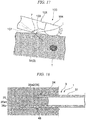
- Fig. 17 is a view for describing an action of the biopsy needle 1.
- Fig. 18 is a schematic view showing a process of performing a biopsy on the tissue using the needle tube 3.
- Fig. 19 is a schematic view showing a cross section perpendicular to a tube axis of a known needle tube.
- Fig. 20 is a schematic view showing a cross section perpendicular to the tube axis X1 of the needle tube 3 of the embodiment.
- Fig. 21 is a schematic view showing a process of performing a biopsy on the tissue using the needle tube 3.
- the biopsy needle 1 of the embodiment is inserted into tissue T of the biopsy target in a state in which the needle tip section 34 of the needle tube 3 protrudes from the sheath 7.
- the insertion end 36a ( Fig. 4 ) of the needle tube 3 pierces the tissue, and a nodal line portion between the outer circumferential surface 32 of the tubular section 31 and the first beveled surface 36 cuts the tissue open.
- the nodal line (the first nodal line 41) between the second beveled surface 37 and the inner circumferential surface 33 of the tubular section 31 and the nodal line (the second nodal line 44) between the third beveled surface 38 and the inner circumferential surface 33 of the tubular section 31 shown in Fig. 4 come in contact with the tissue.
- the tissue is cut open at the position of the first nodal line 41 and the second nodal line 44 and divided into a tissue piece guided into the tubular section 31 and a tissue piece remaining outside the tubular section 31. For this reason, as shown in Fig. 18 , when the needle tube 3 is inserted into the tissue, the tissue piece is guided into the tubular section 31 while being cut away in a substantially columnar shape.
- Fig. 19 shows a cross section of the needle tube obtained by simply cutting a tube obliquely and perpendicular to the tube axis passing a point corresponding to the middle point M shown in Fig. 5 .
- a blade angle (designated by reference numeral ⁇ in Fig. 19 ) corresponding to the blade angle ⁇ in the embodiment is larger than the blade angle ⁇ shown in Fig. 20 . Since a portion of the needle tube 3 having a small blade angle can easily intrude into the tissue, the needle tube 3 of the embodiment has better performance of cutting the tissue open in the vicinity of the middle point M than the needle tube in the related art obtained by simply cutting the tube obliquely.
- the tissue is further captured in the tubular section 31 by suction.
- a suction apparatus or the like (not shown) may be connected to the proximal side of the biopsy needle 1, and suction through the biopsy needle 1 using the suction apparatus or the like becomes possible.
- the needle tube 3 of the embodiment has a wide range of a sharp blade surface (the blade angle ⁇ is less than 90°, more preferably, less than 70°) at the proximal side of the middle point, a larger amount of tissue can be excised.
- the excised tissue can be securely captured in the tubular section 31 by suction.
- the needle tube 3 When the needle tube 3 is pulled back to the second end portion 31b side, the needle tube 3 can be pulled out of the tissue in a state in which a portion of the tissue is held in the tubular section 31 as shown in Fig. 21 . As the biopsy needle 1 is removed to the outside of the body in a state in which the portion of the tissue is held in the tubular section 31, the tissue of the biopsy target can be collected.
- the second beveled surface 37 and the third beveled surface 38 are formed such that the tissue can be cut open at the positions of the first nodal line 41 and the second nodal line 44, incision that allows the tissue to be introduced into the tubular section 31 can be performed by an insertion operation of the needle tube 3.
- a sharp blade surface configured to cut the tissue open can be formed within a wide range.
- the blade surface can be formed within a wide range at the proximal side of the opening portion of the needle tube.
- the biopsy needle of the embodiment since all of the first beveled surface 36, the second beveled surface 37, the third beveled surface 38 and the fourth beveled surface 39 are planes, machining of forming the needle tip section 34 can be easily performed without machining the entire circumference like the Menghini needle in the related art. As a result, the biopsy needle of the embodiment has high producibility.
- the biopsy needle of the present invention can be used to collect a biopsy tissue.
Landscapes
- Health & Medical Sciences (AREA)
- Life Sciences & Earth Sciences (AREA)
- Surgery (AREA)
- Veterinary Medicine (AREA)
- Public Health (AREA)
- General Health & Medical Sciences (AREA)
- Animal Behavior & Ethology (AREA)
- Engineering & Computer Science (AREA)
- Biomedical Technology (AREA)
- Heart & Thoracic Surgery (AREA)
- Pathology (AREA)
- Molecular Biology (AREA)
- Medical Informatics (AREA)
- Radiology & Medical Imaging (AREA)
- Nuclear Medicine, Radiotherapy & Molecular Imaging (AREA)
- Physics & Mathematics (AREA)
- Biophysics (AREA)
- Optics & Photonics (AREA)
- Vascular Medicine (AREA)
- Anesthesiology (AREA)
- Hematology (AREA)
- Surgical Instruments (AREA)
- Ultra Sonic Daignosis Equipment (AREA)
Abstract
Description
- The present invention relates to a biopsy needle.
- Priority is claimed on Japanese Patent Application No.
2015-030449, filed February 19, 2015 - In the related art, medical needles having various needle point shapes are known. For example,
Patent Document 1 discloses a injection needle having a needle point shape constituted of a plurality of surfaces and capable of reducing pain during injection. In addition,Patent Document 2 discloses a biopsy needle body including a needle point structure capable of supplying a cooling gas to tissue in order to limit damage to the tissue serving as a biopsy target. As a needle point shape that seems to be effective in increasing the collected amount of tissue, a Menghini type needle machined such that a sharp blade is formed throughout a circumference of a needle point opening as disclosed inPatent Document 3 is known. -
- [Patent Document 1]
Japanese Unexamined Patent Application, First Publication No.H10-057490 - [Patent Document 2]
Japanese Unexamined Patent Application, First Publication No.2011-000214 - [Patent Document 3]
Japanese Unexamined Patent Application, First Publication No.2008-154842 - The needle point of the biopsy needle is inserted into the tissue serving as a biopsy target to separate the tissue and guides a portion of the tissue into the biopsy needle. Such a biopsy needle is required to collect a sufficient amount of tissue with a small diameter of the needle. However, the Menghini type needle disclosed in
Patent Document 3 requires high machining cost in machining the entire circumference of the needle point, and thus is inappropriate for mass production. The biopsy needle is generally used as a disposable article in consideration of prevention of contamination, and is preferably easy to produce. - In consideration of the above-mentioned circumstances, the present invention is directed to provide a biopsy needle that is easily produced, increases the collected amount of tissue, and has high producibility.
- An aspect of the present invention is a biopsy needle including: a tubular section formed in a hollow tube shape and having a first end portion in a tube axis direction and a second end portion opposite thereto; and a needle tip section having an opening portion in communication with the inside of the tubular section and formed at a position including the first end portion of the tubular section, wherein the needle tip section includes: a first beveled surface constituted of a plane extended in a direction crossing a tube axis of the tubular section and configured to define a part of a contour of the opening portion; a second beveled surface adjacent to the first beveled surface and forming an angle with the first beveled surface, constituted of a plane adjacent to an inner circumferential surface of the tubular section, and configured to define a part of the contour of the opening portion using a nodal line between the inner circumferential surface and the second beveled surface; a third beveled surface adjacent to the first beveled surface and forming an angle with the first beveled surface at an opposite side of the second beveled surface with the opening portion interposed therebetween, constituted of a plane adjacent to the inner circumferential surface of the tubular section, and configured to define a part of the contour of the opening portion using a nodal line between the inner circumferential surface and the third beveled surface; a first boundary line serving as a boundary between the first beveled surface and the second beveled surface; and a second boundary line serving as a boundary between the first beveled surface and the third beveled surface, and the first boundary line and the second boundary line are non-parallel straight lines having an interval that gradually increases in a direction from the second end portion toward the first end portion in the tube axis direction of the tubular section.
- In a cross section crossing the nodal line between the second beveled surface and the inner circumferential surface in a cross section perpendicular to the tube axis of the tubular section, an angle formed between the second beveled surface and the inner circumferential surface may be constantly less than 90°, and in a cross section crossing the nodal line between the third beveled surface and the inner circumferential surface and perpendicular to the tube axis of the tubular section, an angle formed between the third beveled surface and the inner circumferential surface may be constantly less than 90°.
- The opening portion may include a first opening end portion that configures the contour of the opening portion at a position closest to the first end portion in the tube axis direction of the tubular section; and a second opening end portion that configures the contour of the opening portion at a position closest to the second end portion in the tube axis direction of the tubular section, and a cross section perpendicular to the tube axis of the tubular section through a middle point of a line segment that connects the first opening end portion and the second opening end portion may cross the nodal line between the second beveled surface and the inner circumferential surface and the nodal line between the third beveled surface and the inner circumferential surface.
- In the cross section perpendicular to the tube axis of the tubular section through the middle point of the line segment that connects the first opening end portion and the second opening end portion, the angle formed between the second beveled surface and the inner circumferential surface may be less than 70°, and in the cross section, the angle formed between the third beveled surface and the inner circumferential surface may be less than 70°.
- In a cross section crossing the nodal line between the second beveled surface and the inner circumferential surface and perpendicular to the tube axis of the tubular section, the angle formed between the second beveled surface and the inner circumferential surface may be constantly less than 70°, and in a cross section crossing the nodal line between the third beveled surface and the inner circumferential surface and perpendicular to the tube axis of the tubular section, the angle formed between the third beveled surface and the inner circumferential surface may be constantly less than 70°.
- The biopsy needle of the aspect may further have a fourth beveled surface constituted of a plane configured to define a part of the contour of the opening portion at a position closer to the second end portion than the first beveled surface, adjacent to the second beveled surface and the third beveled surface, and disposed between the second beveled surface and the third beveled surface.
- The needle tip section may have a side hole formed at an outer circumferential surface of the tubular section of an opposite side of the first beveled surface and in communication with the inside of the tubular section.
- According to the present invention, it is possible to provide a biopsy needle that is easily produced, increases a collected amount of tissue, and has high producibility.
-
-
Fig. 1 is a general view showing a state in which a biopsy needle of an embodiment of the present invention is attached to an ultrasonic endoscope. -
Fig. 2 is a cross-sectional view of a distal portion of the ultrasonic endoscope. -
Fig. 3 is a perspective view of the biopsy needle. -
Fig. 4 is a perspective view showing a needle tube of the biopsy needle. -
Fig. 5 is a plan view of the needle tube. -
Fig. 6 is a front view of the needle tube. -
Fig. 7 is a cross-sectional view taken along line A-A ofFig. 5 . -
Fig. 8 is a cross-sectional view taken along line B-B ofFig. 5 . -
Fig. 9 is a cross-sectional view taken along line C-C ofFig. 5 . -
Fig. 10 is a cross-sectional view taken along line D-D ofFig. 5 . -
Fig. 11 is a cross-sectional view taken along line E-E ofFig. 5 . -
Fig. 12 is a cross-sectional view taken along line F-F ofFig. 5 . -
Fig. 13 is a cross-sectional view taken along line H-H ofFig. 5 . -
Fig. 14 is a cross-sectional view taken along line G-G ofFig. 13 . -
Fig. 15 is a plan view of the needle tube. -
Fig. 16 is a graph showing a blade angle of the needle tube and a blade angle of another known needle tube. -
Fig. 17 is a view for describing an action of the biopsy needle. -
Fig. 18 is a schematic view showing a process of performing a biopsy on tissue using the needle tube. -
Fig. 19 is a schematic view showing a cross section perpendicular to a tube axis of a known needle tube. -
Fig. 20 is a schematic view showing a cross section perpendicular to a tube axis of the needle tube of the embodiment. -
Fig. 21 is a schematic view showing a process of performing a biopsy on the tissue using the needle tube. - An embodiment of the present invention will be described.
Fig. 1 is a general view showing a state in which a biopsy needle of the embodiment is attached to an ultrasonic endoscope.Fig. 2 is a cross-sectional view of a distal portion of the ultrasonic endoscope. - A
biopsy needle 1 for an endoscope of the embodiment shown inFig. 1 (hereinafter referred to as "thebiopsy needle 1") is a biopsy needle serving as a part of a biopsy system and is combined with anultrasonic endoscope 100 to be used in a biopsy. - First, an example of the endoscope used with the
biopsy needle 1 of the embodiment will be described. Further, a configuration of the endoscope that can be used with thebiopsy needle 1 of the embodiment is not particularly limited. - The
ultrasonic endoscope 100 includes aninsertion section 101 inserted into a body from a distal end thereof, anoperation section 109 attached to a proximal end of theinsertion section 101, auniversal cord 112 having a first end connected to a side portion of theoperation section 109, alight source apparatus 113 connected to a second end of theuniversal cord 112 via abranch cable 112a, anoptical observation unit 114 connected to the second end of theuniversal cord 112 via abranch cable 112b, and anultrasonic observation unit 115 connected to the second end of theuniversal cord 112 via abranch cable 112c. - The
insertion section 101 has a distalhard section 102, abendable section 105, and aflexible tube section 106 that are formed sequentially from a distal side thereof. - The distal
hard section 102 includes anoptical imaging mechanism 103 configured to perform optical observation, and anultrasonic scanning mechanism 104 configured to perform ultrasonic observation. - The
optical imaging mechanism 103 includes various constitutions that are not shown, such as an imaging optical system in which a field of vision is directed toward an inclined forward side of the distalhard section 102, an image sensor such as a CCD, a CMOS, or the like, configured to detect an image of a subject that enters through the imaging optical system, and a CPU or the like configured to control an operation of the image sensor. - The ultrasonic scanning mechanism (a probe) 104 includes an ultrasonic vibrator (not shown) configured to emit and receive ultrasonic waves. The ultrasonic waves which are emitted from the ultrasonic vibrator, hit an observation target, and reflected off the target are received by the ultrasonic vibrator of the
ultrasonic scanning mechanism 104. Theultrasonic scanning mechanism 104 outputs a signal to theultrasonic observation unit 115 based on the ultrasonic waves received by the ultrasonic vibrator. Theultrasonic scanning mechanism 104 of the embodiment is used to acquire an ultrasonic wave image of the tissue serving as the biopsy target and acquire an ultrasonic wave image of aneedle tube 3 in a process of the biopsy procedure. - The
bendable section 105 is formed in a tubular shape. Thebendable section 105 is bent in a predetermined direction by pulling an angle wire (not shown) fixed to adistal end 105a (seeFig. 2 ) of thebendable section 105 and extending to theoperation section 109 in theoperation section 109. Thebendable section 105 of the embodiment can be bent in two directions corresponding to a scanning direction of ultrasonic waves. - In the embodiment, for example, while the endoscope having a small outer diameter of the insertion section and bendable in two directions is used for treatment of a respiratory organ, when treatment of, for example, a digestive organ is performed, an endoscope having a large outer diameter and that is bendable in four direction with a high degree of manipulation freedom may also be used.
- The
flexible tube section 106 is a tubular member fixed to aproximal end 105b of thedistal end 105a of thebendable section 105. Theflexible tube section 106 is flexibly formed such that the distalhard section 102 can be guided to a predetermined position in the lumen tissue or the body cavity. - A
channel 107 through which thebiopsy needle 1 is inserted and a pipe line (not shown) configured to perform air supply, water supply, suction, or the like, are disposed in thebendable section 105 and theflexible tube section 106, respectively. - A first end (a distal end) of the
channel 107 is opened in the vicinity of the distal portion of the distalhard section 102, and a second end (a proximal end) of thechannel 107 is opened at a side surface of a distal side of theoperation section 109. Aproximal port member 108 formed in a flange shape is fixed to the second end (the proximal end) of thechannel 107. Thebiopsy needle 1 used with theultrasonic endoscope 100 can be fixed to theproximal port member 108 . - The
operation section 109 shown inFig. 1 has an outer surface formed such that an operator who uses theultrasonic endoscope 100 can hold theoperation section 109 with his/her hand. Further, theoperation section 109 includes abending operation mechanism 110 configured to pull the angle wire to bend thebendable section 105, and a plurality ofswitches 111 configured to perform air supply, water supply or suction through the pipe line. - The
light source apparatus 113 is an apparatus configured to emit illumination light for imaging using theoptical imaging mechanism 103. - The
optical observation unit 114 is configured to project pictures imaged by the image sensor of theoptical imaging mechanism 103 on amonitor 116. - The
ultrasonic observation unit 115 is configured to receive a signal output from theultrasonic scanning mechanism 104 and generate the image based on the signal to project the image on themonitor 116. - A configuration of the
biopsy needle 1 will be described.Fig. 3 is a perspective view of thebiopsy needle 1. - As shown in
Figs. 1 and3 , thebiopsy needle 1 includes aninsertion body 2 inserted into a body, a manipulation section (a treatment tool manipulation section) 8 configured to manipulate theinsertion body 2, and a stylet (a cored bar) 27. - The
insertion body 2 is a long member that can be attached to thechannel 107 that can protrude from the distal end of theinsertion section 101 of theultrasonic endoscope 100. Theinsertion body 2 includes theneedle tube 3 and atubular sheath 7 through which theneedle tube 3 is inserted. - A configuration of the
needle tube 3 of thebiopsy needle 1 of the embodiment will be described in detail. -
Fig. 4 is a perspective view showing the needle tube of thebiopsy needle 1.Fig. 5 is a plan view of the needle tube.Fig. 6 is a front view of the needle tube.Fig. 7 is a cross-sectional view taken along line A-A ofFig. 5 .Fig. 8 is a cross-sectional view taken along line B-B ofFig. 5 .Fig. 9 is a cross-sectional view taken along line C-C ofFig. 5 .Fig. 10 is a cross-sectional view taken along line D-D ofFig. 5 .Fig. 11 is a cross-sectional view taken along line E-E ofFig. 5 .Fig. 12 is a cross-sectional view taken along line F-F ofFig. 5 .Fig. 13 is a cross-sectional view taken along line H-H ofFig. 5 .Fig. 14 is a cross-sectional view taken along line G-G ofFig. 13 . - As shown in
Fig. 4 , theneedle tube 3 includes atubular section 31 and aneedle tip section 34. Theneedle tube 3 is manipulated to advance and retract in thesheath 7 by themanipulation section 8. Theneedle tip section 34 of theneedle tube 3 can protrude and withdraw from an opening of the distal portion of thesheath 7. - The
tubular section 31 has a hollow tubular shape having an outercircumferential surface 32 and an innercircumferential surface 33. Thetubular section 31 has afirst end portion 31a in a tube axis X1 direction and asecond end portion 31b opposite thereto. Theneedle tip section 34 is formed at thefirst end portion 31a in the tube axis X1 direction of thetubular section 31. The manipulation section 8 (to be described below) is attached to thesecond end portion 31b in the tube axis X1 direction of thetubular section 31. - The
tubular section 31 is flexible and has elasticity so as to be easily returned to a straight state when it is bent by an external force. For example, the material of thetubular section 31 may be an alloy material such as a stainless steel alloy, a nickel titanium alloy, a cobalt chromium alloy, or the like. - In the embodiment, the
first end portion 31a of thetubular section 31 is a distal end that punctures the tissue upon use of apuncture needle 1. Further, thesecond end portion 31b of thetubular section 31 is a proximal end disposed near an operator's hand together with themanipulation section 8 upon use of thepuncture needle 1. - As shown in
Figs. 4 to 6 , theneedle tip section 34 is formed to be sharp enough for theneedle tube 3 to puncture the tissue, and has an openingportion 35 to suction the tissue into theneedle tube 3. - The
needle tip section 34 includes a plurality of beveled surfaces (a firstbeveled surface 36, a secondbeveled surface 37, a thirdbeveled surface 38 and a fourth beveled surface 39) configured to define acontour 35a of the openingportion 35. In addition, theneedle tip section 34 includes afirst boundary line 40 having a linear shape serving as a boundary between the firstbeveled surface 36 and the secondbeveled surface 37, and asecond boundary line 43 having a linear shape serving as a boundary between the firstbeveled surface 36 and the thirdbeveled surface 38. - The opening
portion 35 of theneedle tip section 34 comes in communication with the outside of theneedle tube 3 and the inside of theneedle tube 3. The openingportion 35 includes a first opening end portion 35a1 that constitutes thecontour 35a of the openingportion 35 at a position closest to thefirst end portion 31a in the tube axis X1 direction of thetubular section 31, and a second opening end portion 35a2 that constitutes thecontour 35a of the openingportion 35 at a position closest to thesecond end portion 31b in the tube axis X1 direction of thetubular section 31. - The first
beveled surface 36 defines a portion constituted of a plane extended in a direction crossing the tube axis X1 of thetubular section 31 and including the first opening end portion 35a1 in thecontour 35a of the openingportion 35. In addition, the firstbeveled surface 36 includes aninsertion end 36a configured for insertion of theneedle tube 3 into the tissue. - As shown in
Fig. 6 , the secondbeveled surface 37 forms an angle with the firstbeveled surface 36 and is adjacent to the firstbeveled surface 36. Further, as shown inFig. 9 , the secondbeveled surface 37 is constituted of a plane adjacent to the innercircumferential surface 33 of thetubular section 31, and a nodal line (a first nodal line 41) to the innercircumferential surface 33 defines a part of thecontour 35a of the openingportion 35. - As shown in
Fig. 9 , in a cross section perpendicular to the tube axis X1 of thetubular section 31, an angle formed between the secondbeveled surface 37 and the innercircumferential surface 33 is an angle θ1 formed between a tangential line La of the innercircumferential surface 33 and the secondbeveled surface 37 at an intersection point Pa between the cross section and the firstnodal line 41. - In a cross-section perpendicular to the tube axis X1 of the
tubular section 31 through a middle point M (seeFig. 5 ) of a line segment that connects the first opening end portion 35a1 and the second opening end portion 35a2, the angle θ1 formed between the secondbeveled surface 37 and the innercircumferential surface 33 is less than 90°. In particular, in the embodiment, in a cross section crossing the firstnodal line 41 between the secondbeveled surface 37 and the innercircumferential surface 33 in the cross section perpendicular to the tube axis X1 of thetubular section 31, an angle formed between the secondbeveled surface 37 and the innercircumferential surface 33 is constantly less than 90°. For this reason, a region including the firstnodal line 41 functions as a blade that can cut the tissue open. - As shown in
Fig. 6 , the thirdbeveled surface 38 forms an angle with the firstbeveled surface 36 at an opposite side of the secondbeveled surface 37 with the openingportion 35 sandwiched therebetween and is adjacent to the firstbeveled surface 36. Further, as shown inFig. 9 , the thirdbeveled surface 38 is constituted of a plane adjacent to the innercircumferential surface 33 of thetubular section 31. A nodal line (a second nodal line 44) of the thirdbeveled surface 38 to the innercircumferential surface 33 of thetubular section 31 defines a part of thecontour 35a of the openingportion 35. - As shown in
Fig. 9 , in a cross section perpendicular to the tube axis X1 of thetubular section 31, an angle formed between the thirdbeveled surface 38 and the innercircumferential surface 33 is an angle θ2 formed between a tangential line Lb of the innercircumferential surface 33 and the thirdbeveled surface 38 at an intersection point Pb between the cross section and the secondnodal line 44. - In a cross section perpendicular to the tube axis X1 of the
tubular section 31 through the middle point M (seeFig. 5 ) of the line segment that connects the first opening end portion 35a1 and the second opening end portion 35a2, the angle θ2 formed between the thirdbeveled surface 38 and the innercircumferential surface 33 is less than 90°. In particular, in the embodiment, in a cross section crossing the secondnodal line 44 between the thirdbeveled surface 38 and the innercircumferential surface 33 in the cross section perpendicular to the tube axis X1 of thetubular section 31, an angle formed between the thirdbeveled surface 38 and the innercircumferential surface 33 is constantly less than 90°. For this reason, a region including the secondnodal line 44 functions as a blade that can cut the tissue open. - As shown in
Figs. 4 to 6 , thefirst boundary line 40 and thesecond boundary line 43 are non-parallel straight lines having an interval that gradually increases in a direction from thesecond end portion 31b toward thefirst end portion 31a in the tube axis X1 direction of thetubular section 31. - As shown in
Figs. 5 and6 , the fourthbeveled surface 39 is constituted of a plane adjacent to the secondbeveled surface 37 and the thirdbeveled surface 38 and disposed between the secondbeveled surface 37 and the thirdbeveled surface 38. Anodal line 42 between the fourthbeveled surface 39 and the secondbeveled surface 37 is a straight line coaxial with thefirst boundary line 40 shown inFig. 5 . Anodal line 45 between the fourthbeveled surface 39 and the thirdbeveled surface 38 is a straight line coaxial with thesecond boundary line 43 shown inFig. 5 . The fourthbeveled surface 39 defines a portion including the second opening end portion 35a2 in thecontour 35a of the openingportion 35 at a position closer to thesecond end portion 31b than the firstbeveled surface 36. - In addition, the
needle tip section 34 of thebiopsy needle 1 of the embodiment undergoes back-cut processing to be inclined from theinsertion end 36a toward an opposite side of the firstbeveled surface 36. As shown inFig. 6 , surfaces (a fifthbeveled surface 46 and a sixth beveled surface 47) formed through the back-cut processing are formed at theneedle tip section 34 of thebiopsy needle 1. As the fifthbeveled surface 46 and the sixthbeveled surface 47 are formed at theneedle tip section 34, theinsertion end 36a of theneedle tip section 34 becomes an intersection point of three planes of the firstbeveled surface 36, the fifthbeveled surface 46 and the sixthbeveled surface 47. For this reason, in the embodiment, puncture performance when theinsertion end 36a punctures the tissue is high. Further, when the back-cut processing is performed as described in the embodiment, theinsertion end 36a cannot easily pierce the inner wall of thechannel 107 in a process in which theneedle tip section 34 passes through the bent section of thechannel 107 of the endoscope. - Further, the back-cut processing may be not performed on the
needle tip section 34. - In addition, further, as shown in
Figs. 13 and 14 , theneedle tube 3 of thebiopsy needle 1 of the embodiment may have aside hole section 48 in which a substantially rectangular through-hole is formed to come in communication with the inside and the outside of thetubular section 31. - As the above-mentioned
side hole section 48 is provided, the tissue captured from the openingportion 35 can be hooked by an edge of theside hole section 48 so that it does not easily fall out, or a collected tissue amount can be further increased by further capturing the tissue in thetubular section 31 via theside hole section 48. - Further, a shape of the opening of the
side hole section 48 is not limited to a substantially rectangular shape but a shape of the opening may be a circular shape. In addition, theside hole section 48 may not come in communication with the inside and the outside of thetubular section 31 but may be a concave section formed to be recessed with respect to the innercircumferential surface 33 of thetubular section 31. - Next, a structure of the
needle tip section 34 of the embodiment will be described in more detail in comparison with the known Menghini needle and a needle in the related art in which a tube is simply cut obliquely.Fig. 15 is a plan view of theneedle tube 3.Fig. 16 is a graph showing a blade angle of theneedle tube 3 and a blade angle of another known needle tube. -
Fig. 16 shows an angle (hereinafter referred to as "a blade angle α," seeFigs. 7 to 12 ) formed between the innercircumferential surface 33 of thetubular section 31 and another surface adjacent to the innercircumferential surface 33 in the cross section perpendicular to the tube axis X1 of theneedle tube 3. A horizontal axis inFig. 16 represents a position of the cross section in the tube axis X1 direction when a position of the second opening end portion 35a2 is 1 using a position of the first opening end portion 35a1 as an origin in the tube axis X1 direction. A vertical axis represents the blade angle α at each position. - In
Fig. 16 , □ relates to thebiopsy needle 1 of the embodiment, ◆ relates to the Menghini needle, and Δ relates a needle on which back-cut processing is performed simply by diagonal cutting. □, ◆ and Δ inFig. 16 represent the blade angles α obtained by equally dividing a space between an origin (0) in the tube axis X1 direction and a position (1) of the second opening end portion 35a2 into 16 regions. In addition, inFig. 16 , ● represents the blade angles α at positions O, A, B, C, D, E and F in the tube axis X1 direction of thebiopsy needle 1 of the embodiment. - The positions O, A, B, C, D, E and F (see
Figs. 5 and15 ) in the tube axis X1 direction of thebiopsy needle 1 are positions defined as follows. - The position O is a position of a cross section including the first opening end portion 35a1.
- The position A is a position of a cross section including an end closest to the
first end portion 31a in thefirst boundary line 40 and thesecond boundary line 43. At the position A, the blade angle α is defined by the innercircumferential surface 33 and the firstbeveled surface 36. - The position B is a position of a cross section including the inner
circumferential surface 33, the firstbeveled surface 36, the secondbeveled surface 37 and the thirdbeveled surface 38. At the position B, the blade angle α is defined by the innercircumferential surface 33 and the firstbeveled surface 36. - The position C is a position of a cross section including an end closest to the
second end portion 31b in thefirst boundary line 40 and thesecond boundary line 43. At the position C, each of the blade angles α is defined by the innercircumferential surface 33 and the secondbeveled surface 37, or the innercircumferential surface 33 and the thirdbeveled surface 38. - The position D is a position of a cross section including an intersection point between the inner
circumferential surface 33, the secondbeveled surface 37 and the fourthbeveled surface 39, and an intersection point between the innercircumferential surface 33, the thirdbeveled surface 38 and the fourthbeveled surface 39. At the position D, each of the blade angles α is defined by the innercircumferential surface 33 and the secondbeveled surface 37, or the innercircumferential surface 33 and the thirdbeveled surface 38. - The position E is a position of a cross section including the inner
circumferential surface 33, the secondbeveled surface 37, the thirdbeveled surface 38 and the fourthbeveled surface 39. At the position E, the blade angle α is defined by the innercircumferential surface 33 and the fourthbeveled surface 39. - The position F is a position of a cross section including the second opening end portion 35a2.
- As shown in
Fig. 16 , in a region from the position C to the position D in thebiopsy needle 1 of the embodiment, the blade angle α is smaller than that of the needle formed by simple diagonal cutting. The blade angle α (Figs. 9 and10 ) in the region from the position C to the position D in thebiopsy needle 1 of the embodiment has substantially the same configuration as that of the Menghini needle. The position C is a position closer to thefirst end portion 31a than a middle point between the first opening end portion 35a1 and the second opening end portion 35a2 in a tube axis X direction. Here, in thebiopsy needle 1 of the embodiment, the openingportion 35 has a contour shape that forms a generally oval shape such that the width thereof is gradually reduced from a middle point between the first opening end portion 35a1 and the second opening end portion 35a2 toward thesecond end portion 31b. - The blade angle α at the position C in the
biopsy needle 1 of the embodiment is less than 90°, and the blade angle α at the middle point between the first opening end portion 35a1 and the second opening end portion 35a2 in the tube axis X direction is also less than 90°. - Further, the middle point between the first opening end portion 35a1 and the second opening end portion 35a2 is disposed in a range in which the nodal line (the first nodal line 41) between the second
beveled surface 37 and the innercircumferential surface 33 of thetubular section 31 and the nodal line (the second nodal line 44) between the thirdbeveled surface 38 and the innercircumferential surface 33 of thetubular section 31 are formed (between the position C and the position D) in the tube axis X1 direction. - In this way, in an intermediate region (including the position C and the middle point M) of the
needle tip section 34 of the embodiment in which the blade angle α of the needle obtained by simply obliquely cutting a tube is about 90°, the blade angle α is less than 90°, in particular, in the embodiment, less than 70° (more specifically, about 60°, substantially equal to the Menghini needle). That is, a blade having an action of cutting the tissue open to substantially the same or a greater extent than the Menghini needle is formed at theneedle tip section 34 of the embodiment from the position C to the position F. Further, in the region from the position D to the position F, as shown inFig. 16 , while the blade angle α (seeFigs. 11 and 12 ) is larger than that in the case of the Menghini needle, since the blade angle α from the position D to the position F is sufficiently smaller than 90°, the blade angle α is sufficient for performing an action of cutting the tissue open. - The rest of configuration of the
biopsy needle 1 will be described. - As shown in
Fig. 3 , thesheath 7 is a tubular member into which theneedle tube 3 is inserted. Thesheath 7 is formed of a resin, a metal, or the like. A distal end of thesheath 7 is opened such that theneedle tube 3 can protrude. A proximal end of thesheath 7 is fixed to a distal portion of themanipulation section 8. - As shown in
Fig. 3 , themanipulation section 8 includes a manipulationmain body 9, asheath adjuster 18 disposed at a distal side of the manipulationmain body 9, and aneedle slider 23 disposed at a proximal side of the manipulationmain body 9. - The manipulation
main body 9 is formed of, for example, ABS resin or the like, and has a lumen through which theneedle tube 3 and thesheath 7 are inserted. The distal side of the manipulationmain body 9 is inserted into thesheath adjuster 18 formed in a tubular shape. The proximal side of the manipulationmain body 9 is inserted into theneedle slider 23 formed in a tubular shape. The manipulationmain body 9 and thesheath adjuster 18, and the manipulationmain body 9 and theneedle slider 23 can slide in an axial direction while relative rotation around the axis is restricted by grooves, convex sections, or the like (not shown), formed in an outer circumferential surface engaging with each other. Astopper 10 configured to position theneedle slider 23 is provided at the manipulationmain body 9. - A distal portion of the
sheath adjuster 18 can be attached to theultrasonic endoscope 100. - A concavo-convex portion that enables easy gripping by an operator may be formed at an outer circumferential surface of the distal portion of the
sheath adjuster 18. - The
needle slider 23 shown inFig. 3 is a tubular member configured to hold thesecond end portion 31b (seeFig. 5 ) of thetubular section 31 of theneedle tube 3. The proximal portion (thesecond end portion 31b side) of theneedle tube 3 extends from the proximal end of thesheath 7 shown inFig. 3 to the inside of theneedle slider 23 shown inFig. 3 . Theneedle slider 23 is connected to the manipulationmain body 9 to be movable with respect to the manipulationmain body 9. - In the embodiment, a manipulation stroke length of the
needle tube 3 by theneedle slider 23 is 40 mm or more. Further, the manipulation stroke length of theneedle tube 3 by theneedle slider 23 is less than 40 mm. - A concavo-convex portion that enables easy gripping by an operator may be formed at an outer circumferential surface of the distal portion of the
needle slider 23. - The
stylet 27 shown inFig. 3 is a wire-shaped member having a knob that can be attached to theneedle slider 23 and a cross-sectional shape corresponding to an inner surface shape of theneedle tube 3. - An action of the
biopsy needle 1 of the embodiment will be described.Fig. 17 is a view for describing an action of thebiopsy needle 1.Fig. 18 is a schematic view showing a process of performing a biopsy on the tissue using theneedle tube 3.Fig. 19 is a schematic view showing a cross section perpendicular to a tube axis of a known needle tube.Fig. 20 is a schematic view showing a cross section perpendicular to the tube axis X1 of theneedle tube 3 of the embodiment.Fig. 21 is a schematic view showing a process of performing a biopsy on the tissue using theneedle tube 3. - As shown in
Fig. 17 , thebiopsy needle 1 of the embodiment is inserted into tissue T of the biopsy target in a state in which theneedle tip section 34 of theneedle tube 3 protrudes from thesheath 7. In a process in which theneedle tip section 34 of theneedle tube 3 is inserted into the tissue, first, theinsertion end 36a (Fig. 4 ) of theneedle tube 3 pierces the tissue, and a nodal line portion between the outercircumferential surface 32 of thetubular section 31 and the firstbeveled surface 36 cuts the tissue open. - When the
needle tube 3 is further inserted into the tissue after theinsertion end 36a of theneedle tube 3 pierces the tissue as shown inFig. 18 , the nodal line (the first nodal line 41) between the secondbeveled surface 37 and the innercircumferential surface 33 of thetubular section 31 and the nodal line (the second nodal line 44) between the thirdbeveled surface 38 and the innercircumferential surface 33 of thetubular section 31 shown inFig. 4 come in contact with the tissue. In the embodiment, since the region including the firstnodal line 41 and the secondnodal line 44 functions as a blade that can cut the tissue open, the tissue is cut open at the position of the firstnodal line 41 and the secondnodal line 44 and divided into a tissue piece guided into thetubular section 31 and a tissue piece remaining outside thetubular section 31. For this reason, as shown inFig. 18 , when theneedle tube 3 is inserted into the tissue, the tissue piece is guided into thetubular section 31 while being cut away in a substantially columnar shape. -
Fig. 19 shows a cross section of the needle tube obtained by simply cutting a tube obliquely and perpendicular to the tube axis passing a point corresponding to the middle point M shown inFig. 5 . In the above-mentioned needle tube in the related art, a blade angle (designated by reference numeral β inFig. 19 ) corresponding to the blade angle α in the embodiment is larger than the blade angle α shown inFig. 20 . Since a portion of theneedle tube 3 having a small blade angle can easily intrude into the tissue, theneedle tube 3 of the embodiment has better performance of cutting the tissue open in the vicinity of the middle point M than the needle tube in the related art obtained by simply cutting the tube obliquely. - After the
needle tube 3 is inserted into the tissue, the tissue is further captured in thetubular section 31 by suction. For example, a suction apparatus or the like (not shown) may be connected to the proximal side of thebiopsy needle 1, and suction through thebiopsy needle 1 using the suction apparatus or the like becomes possible. Here, in comparison with the needle tube in the related art obtained by simply cutting the tube obliquely, since theneedle tube 3 of the embodiment has a wide range of a sharp blade surface (the blade angle α is less than 90°, more preferably, less than 70°) at the proximal side of the middle point, a larger amount of tissue can be excised. The excised tissue can be securely captured in thetubular section 31 by suction. - When the
needle tube 3 is pulled back to thesecond end portion 31b side, theneedle tube 3 can be pulled out of the tissue in a state in which a portion of the tissue is held in thetubular section 31 as shown inFig. 21 . As thebiopsy needle 1 is removed to the outside of the body in a state in which the portion of the tissue is held in thetubular section 31, the tissue of the biopsy target can be collected. - As described above, in the embodiment, since the second
beveled surface 37 and the thirdbeveled surface 38 are formed such that the tissue can be cut open at the positions of the firstnodal line 41 and the secondnodal line 44, incision that allows the tissue to be introduced into thetubular section 31 can be performed by an insertion operation of theneedle tube 3. - In addition, in comparison with the needle tube in the related art obtained by simply cutting the tube obliquely, a sharp blade surface (the blade angle α is less than 90°, more preferably less than 70°, and further preferably about 60°, substantially equal to the Menghini needle) configured to cut the tissue open can be formed within a wide range. In particular, the blade surface can be formed within a wide range at the proximal side of the opening portion of the needle tube.
- In addition, in the embodiment, since all of the first
beveled surface 36, the secondbeveled surface 37, the thirdbeveled surface 38 and the fourthbeveled surface 39 are planes, machining of forming theneedle tip section 34 can be easily performed without machining the entire circumference like the Menghini needle in the related art. As a result, the biopsy needle of the embodiment has high producibility. - Hereinabove, while the embodiment of the present invention has been described in detail with reference to the accompanying drawings, a specific configuration is not limited to the embodiment but may include design changes and so on without departing from the spirit of the present invention.
- The biopsy needle of the present invention can be used to collect a biopsy tissue.
-
- 1 Biopsy needle
- 2 Insertion body
- 3 Needle tube
- 7 Sheath
- 8 Manipulation section (treatment tool manipulation section)
- 9 Manipulation main body
- 10 Stopper
- 18 Sheath adjuster
- 23 Needle slider
- 24 Holding section
- 27 Stylet
- 31 Tubular section
- 31a First end portion
- 31b Second end portion
- 32 Outer circumferential surface
- 33 Inner circumferential surface
- 34 Needle tip section
- 35 Opening portion
- 35a Contour
- 35a1 First opening end portion
- 35a2 Second opening end portion
- 36 First beveled surface
- 36a Insertion end
- 37 Second beveled surface
- 38 Third beveled surface
- 39 Fourth beveled surface
- 40 First boundary line
- 41 First nodal line
- 42 Nodal line
- 43 Second boundary line
- 44 Second nodal line
- 45 Nodal line
- 46 Fifth beveled surface
- 47 Sixth beveled surface
- 48 Side hole section
- 49 Distal corner section
- 50 Proximal corner section
- 100 Ultrasonic endoscope
- 101 Insertion section
- 102 Distal hard section
- 103 Optical imaging mechanism
- 104 Ultrasonic scanning mechanism
- 105 Bendable section
- 106 Flexible tube section
- 107 Channel
- 108 Proximal port member
- 109 Operation section
- 110 Bending operation mechanism
- 111 Switch
- 112 Universal cord
- 112a Branch cable
- 112b Branch cable
- 112c Branch cable
- 113 Light source apparatus
- 114 Optical observation unit
- 115 Ultrasonic observation unit
- 116 Monitor
Claims (7)
- A biopsy needle comprising:a tubular section formed in a hollow tube shape and having a first end portion in a tube axis direction and a second end portion opposite thereto; anda needle tip section having an opening portion in communication with the inside of the tubular section and formed at a position including the first end portion of the tubular section,wherein the needle tip section includes:a first beveled surface constituted of a plane extended in a direction crossing a tube axis of the tubular section and configured to define a part of a contour of the opening portion;a second beveled surface adjacent to the first beveled surface and forming an angle with the first beveled surface, constituted of a plane adjacent to an inner circumferential surface of the tubular section, and configured to define a part of the contour of the opening portion using a nodal line between the inner circumferential surface and the second beveled surface;a third beveled surface adjacent to the first beveled surface and forming an angle with the first beveled surface at an opposite side of the second beveled surface with the opening portion interposed therebetween, constituted of a plane adjacent to the inner circumferential surface of the tubular section, and configured to define a part of the contour of the opening portion using a nodal line between the inner circumferential surface and the third beveled surface;a first boundary line serving as a boundary between the first beveled surface and the second beveled surface; anda second boundary line serving as a boundary between the first beveled surface and the third beveled surface, andthe first boundary line and the second boundary line are non-parallel straight lines having an interval that gradually increases in a direction from the second end portion toward the first end portion in the tube axis direction of the tubular section.
- The biopsy needle according to claim 1, wherein, in a cross section crossing the nodal line between the second beveled surface and the inner circumferential surface and perpendicular to the tube axis of the tubular section, an angle formed between the second beveled surface and the inner circumferential surface is constantly less than 90°, and
in a cross section crossing the nodal line between the third beveled surface and the inner circumferential surface and perpendicular to the tube axis of the tubular section, an angle formed between the third beveled surface and the inner circumferential surface is constantly less than 90°. - The biopsy needle according to claim 2, wherein the opening portion includes:a first opening end portion that configures the contour of the opening portion at a position closest to the first end portion in the tube axis direction of the tubular section; anda second opening end portion that configures the contour of the opening portion at a position closest to the second end portion in the tube axis direction of the tubular section, anda cross section perpendicular to the tube axis of the tubular section through a middle point of a line segment that connects the first opening end portion and the second opening end portion crosses the nodal line between the second beveled surface and the inner circumferential surface and the nodal line between the third beveled surface and the inner circumferential surface.
- The biopsy needle according to claim 3, wherein, in the cross section perpendicular to the tube axis of the tubular section through the middle point of the line segment that connects the first opening end portion and the second opening end portion, the angle formed between the second beveled surface and the inner circumferential surface is less than 70°, and
in the cross section, the angle formed between the third beveled surface and the inner circumferential surface is less than 70°. - The biopsy needle according to claim 4, wherein, in the cross section crossing the nodal line between the second beveled surface and the inner circumferential surface and perpendicular to the tube axis of the tubular section, the angle formed between the second beveled surface and the inner circumferential surface is constantly less than 70°, and
in the cross section crossing the nodal line between the third beveled surface and the inner circumferential surface and perpendicular to the tube axis of the tubular section, the angle formed between the third beveled surface and the inner circumferential surface is constantly less than 70°. - The biopsy needle according to claim 1, further comprising a fourth beveled surface constituted of a plane configured to define a part of the contour of the opening portion at a position closer to the second end portion than the first beveled surface, adjacent to the second beveled surface and the third beveled surface, and disposed between the second beveled surface and the third beveled surface.
- The biopsy needle according to claim 1, wherein the needle tip section has a side hole formed at an outer circumferential surface of the tubular section of an opposite side of the first beveled surface and in communication with the inside of the tubular section.
Applications Claiming Priority (2)
| Application Number | Priority Date | Filing Date | Title |
|---|---|---|---|
| JP2015030449 | 2015-02-19 | ||
| PCT/JP2015/075723 WO2016132577A1 (en) | 2015-02-19 | 2015-09-10 | Biopsy needle |
Publications (3)
| Publication Number | Publication Date |
|---|---|
| EP3260050A1 true EP3260050A1 (en) | 2017-12-27 |
| EP3260050A4 EP3260050A4 (en) | 2018-11-14 |
| EP3260050B1 EP3260050B1 (en) | 2020-01-15 |
Family
ID=56692073
Family Applications (1)
| Application Number | Title | Priority Date | Filing Date |
|---|---|---|---|
| EP15882678.4A Active EP3260050B1 (en) | 2015-02-19 | 2015-09-10 | Biopsy needle |
Country Status (4)
| Country | Link |
|---|---|
| US (1) | US9610067B2 (en) |
| EP (1) | EP3260050B1 (en) |
| CN (1) | CN106068101B (en) |
| WO (1) | WO2016132577A1 (en) |
Cited By (1)
| Publication number | Priority date | Publication date | Assignee | Title |
|---|---|---|---|---|
| CN110075395A (en) * | 2019-05-22 | 2019-08-02 | 贝普医疗科技有限公司 | A kind of five inclined-plane needle tubings of injection |
Families Citing this family (4)
| Publication number | Priority date | Publication date | Assignee | Title |
|---|---|---|---|---|
| EP3437677B1 (en) * | 2016-03-28 | 2021-07-14 | Terumo Kabushiki Kaisha | Medical puncture needle and method for manufacturing puncture needle |
| CA3023978C (en) | 2016-05-25 | 2020-09-01 | 3Dbiopsy, Inc. | Biopsy needle design |
| US10820893B2 (en) * | 2017-02-15 | 2020-11-03 | Cook Medical Technologies Llc | Endoscopic tri-point biopsy needle |
| US20210154436A1 (en) * | 2019-11-22 | 2021-05-27 | Becton, Dickinson And Company | Introducer needle and related devices, systems, and methods |
Family Cites Families (15)
| Publication number | Priority date | Publication date | Assignee | Title |
|---|---|---|---|---|
| US3090384A (en) * | 1960-04-15 | 1963-05-21 | Mfg Process Lab Inc | Needle |
| US5477862A (en) * | 1994-03-14 | 1995-12-26 | Haaga; John R. | Cutting tip for biopsy needle |
| US5752942A (en) * | 1996-06-20 | 1998-05-19 | Becton Dickinson And Company | Five beveled point geometry for a hypodermic needle |
| DE10026508A1 (en) * | 2000-05-24 | 2001-11-29 | Kai Desinger | Surgical hollow tube |
| KR100706009B1 (en) * | 2000-07-03 | 2007-04-11 | 도쿠타 쟈판 가부시키가이샤 | Medical bevel needle |
| US20030069550A1 (en) * | 2001-10-06 | 2003-04-10 | Sharp M. Keith | Hypodermic needle |
| US20090204021A1 (en) * | 2004-12-16 | 2009-08-13 | Senorx, Inc. | Apparatus and method for accessing a body site |
| RU2008152754A (en) * | 2006-06-02 | 2010-07-20 | Асахи Полислайдер Компани, Лимитед (Jp) | PUNCHING NEEDLE AND Lancet FITTED WITH SUCH NEEDLE |
| JP2008154842A (en) | 2006-12-25 | 2008-07-10 | Nisshin Kogu Kk | Injection needle |
| US8622924B2 (en) * | 2008-02-27 | 2014-01-07 | Devicor Medical Products, Inc. | Needle tip for biopsy device |
| JP5524516B2 (en) | 2009-06-17 | 2014-06-18 | 株式会社パイロットコーポレーション | Biological needle body and tissue collection device |
| EP2744396B1 (en) * | 2011-10-13 | 2022-02-09 | Koninklijke Philips N.V. | Medical probe with multi-fiber lumen |
| WO2014045677A1 (en) * | 2012-09-21 | 2014-03-27 | オリンパスメディカルシステムズ株式会社 | Biopsy needle and biopsy system |
| JP5577000B1 (en) * | 2012-10-05 | 2014-08-20 | オリンパスメディカルシステムズ株式会社 | Biopsy tool |
| JP3187362U (en) * | 2013-09-11 | 2013-11-21 | 株式会社タスク | Blood collection puncture needle |
-
2015
- 2015-09-10 CN CN201580011140.1A patent/CN106068101B/en active Active
- 2015-09-10 WO PCT/JP2015/075723 patent/WO2016132577A1/en active Application Filing
- 2015-09-10 EP EP15882678.4A patent/EP3260050B1/en active Active
-
2016
- 2016-08-31 US US15/252,997 patent/US9610067B2/en active Active
Cited By (1)
| Publication number | Priority date | Publication date | Assignee | Title |
|---|---|---|---|---|
| CN110075395A (en) * | 2019-05-22 | 2019-08-02 | 贝普医疗科技有限公司 | A kind of five inclined-plane needle tubings of injection |
Also Published As
| Publication number | Publication date |
|---|---|
| US20160367232A1 (en) | 2016-12-22 |
| CN106068101A (en) | 2016-11-02 |
| WO2016132577A1 (en) | 2016-08-25 |
| EP3260050A4 (en) | 2018-11-14 |
| EP3260050B1 (en) | 2020-01-15 |
| US9610067B2 (en) | 2017-04-04 |
| CN106068101B (en) | 2019-05-28 |
Similar Documents
| Publication | Publication Date | Title |
|---|---|---|
| JP5629043B1 (en) | Biopsy system | |
| US9610067B2 (en) | Biopsy needle | |
| US8708931B2 (en) | Treatment tool for biopsy and tissue collecting method | |
| US9693803B2 (en) | Puncture needle for endoscope and biopsy system | |
| US9955956B2 (en) | Needle tube | |
| WO2015190188A1 (en) | Biopsy system | |
| WO2016047202A1 (en) | Endoscope puncture needle | |
| JP7442003B2 (en) | Puncture needle for endoscope | |
| WO2016042849A1 (en) | Biopsy system | |
| EP2762054A1 (en) | Treatment device and endoscopic treatment system | |
| JP5945651B1 (en) | Biopsy needle | |
| JP6284464B2 (en) | Endoscopic puncture needle | |
| JP5893814B1 (en) | Tissue collection system | |
| WO2015190187A1 (en) | Endoscopic treatment instrument and biopsy system | |
| US11229423B2 (en) | Tissue collecting instrument | |
| US20150094614A1 (en) | Biopsy instrument |
Legal Events
| Date | Code | Title | Description |
|---|---|---|---|
| STAA | Information on the status of an ep patent application or granted ep patent |
Free format text: STATUS: THE INTERNATIONAL PUBLICATION HAS BEEN MADE |
|
| PUAI | Public reference made under article 153(3) epc to a published international application that has entered the european phase |
Free format text: ORIGINAL CODE: 0009012 |
|
| STAA | Information on the status of an ep patent application or granted ep patent |
Free format text: STATUS: REQUEST FOR EXAMINATION WAS MADE |
|
| 17P | Request for examination filed |
Effective date: 20170904 |
|
| AK | Designated contracting states |
Kind code of ref document: A1 Designated state(s): AL AT BE BG CH CY CZ DE DK EE ES FI FR GB GR HR HU IE IS IT LI LT LU LV MC MK MT NL NO PL PT RO RS SE SI SK SM TR |
|
| AX | Request for extension of the european patent |
Extension state: BA ME |
|
| DAV | Request for validation of the european patent (deleted) | ||
| DAX | Request for extension of the european patent (deleted) | ||
| A4 | Supplementary search report drawn up and despatched |
Effective date: 20181016 |
|
| RIC1 | Information provided on ipc code assigned before grant |
Ipc: A61B 8/00 20060101ALI20181010BHEP Ipc: A61B 1/00 20060101ALI20181010BHEP Ipc: A61M 5/32 20060101ALI20181010BHEP Ipc: A61B 10/02 20060101AFI20181010BHEP Ipc: A61B 1/018 20060101ALI20181010BHEP Ipc: A61B 10/04 20060101ALI20181010BHEP Ipc: A61B 8/12 20060101ALI20181010BHEP Ipc: A61B 8/08 20060101ALI20181010BHEP |
|
| GRAP | Despatch of communication of intention to grant a patent |
Free format text: ORIGINAL CODE: EPIDOSNIGR1 |
|
| STAA | Information on the status of an ep patent application or granted ep patent |
Free format text: STATUS: GRANT OF PATENT IS INTENDED |
|
| INTG | Intention to grant announced |
Effective date: 20190531 |
|
| GRAS | Grant fee paid |
Free format text: ORIGINAL CODE: EPIDOSNIGR3 |
|
| GRAJ | Information related to disapproval of communication of intention to grant by the applicant or resumption of examination proceedings by the epo deleted |
Free format text: ORIGINAL CODE: EPIDOSDIGR1 |
|
| GRAL | Information related to payment of fee for publishing/printing deleted |
Free format text: ORIGINAL CODE: EPIDOSDIGR3 |
|
| STAA | Information on the status of an ep patent application or granted ep patent |
Free format text: STATUS: REQUEST FOR EXAMINATION WAS MADE |
|
| INTC | Intention to grant announced (deleted) | ||
| GRAP | Despatch of communication of intention to grant a patent |
Free format text: ORIGINAL CODE: EPIDOSNIGR1 |
|
| STAA | Information on the status of an ep patent application or granted ep patent |
Free format text: STATUS: GRANT OF PATENT IS INTENDED |
|
| INTG | Intention to grant announced |
Effective date: 20191113 |
|
| GRAA | (expected) grant |
Free format text: ORIGINAL CODE: 0009210 |
|
| STAA | Information on the status of an ep patent application or granted ep patent |
Free format text: STATUS: THE PATENT HAS BEEN GRANTED |
|
| AK | Designated contracting states |
Kind code of ref document: B1 Designated state(s): AL AT BE BG CH CY CZ DE DK EE ES FI FR GB GR HR HU IE IS IT LI LT LU LV MC MK MT NL NO PL PT RO RS SE SI SK SM TR |
|
| REG | Reference to a national code |
Ref country code: CH Ref legal event code: EP Ref country code: GB Ref legal event code: FG4D |
|
| REG | Reference to a national code |
Ref country code: IE Ref legal event code: FG4D |
|
| REG | Reference to a national code |
Ref country code: DE Ref legal event code: R096 Ref document number: 602015045824 Country of ref document: DE |
|
| REG | Reference to a national code |
Ref country code: AT Ref legal event code: REF Ref document number: 1224459 Country of ref document: AT Kind code of ref document: T Effective date: 20200215 |
|
| REG | Reference to a national code |
Ref country code: NL Ref legal event code: MP Effective date: 20200115 |
|
| REG | Reference to a national code |
Ref country code: LT Ref legal event code: MG4D |
|
| PG25 | Lapsed in a contracting state [announced via postgrant information from national office to epo] |
Ref country code: FI Free format text: LAPSE BECAUSE OF FAILURE TO SUBMIT A TRANSLATION OF THE DESCRIPTION OR TO PAY THE FEE WITHIN THE PRESCRIBED TIME-LIMIT Effective date: 20200115 Ref country code: PT Free format text: LAPSE BECAUSE OF FAILURE TO SUBMIT A TRANSLATION OF THE DESCRIPTION OR TO PAY THE FEE WITHIN THE PRESCRIBED TIME-LIMIT Effective date: 20200607 Ref country code: NL Free format text: LAPSE BECAUSE OF FAILURE TO SUBMIT A TRANSLATION OF THE DESCRIPTION OR TO PAY THE FEE WITHIN THE PRESCRIBED TIME-LIMIT Effective date: 20200115 Ref country code: RS Free format text: LAPSE BECAUSE OF FAILURE TO SUBMIT A TRANSLATION OF THE DESCRIPTION OR TO PAY THE FEE WITHIN THE PRESCRIBED TIME-LIMIT Effective date: 20200115 Ref country code: NO Free format text: LAPSE BECAUSE OF FAILURE TO SUBMIT A TRANSLATION OF THE DESCRIPTION OR TO PAY THE FEE WITHIN THE PRESCRIBED TIME-LIMIT Effective date: 20200415 |
|
| PG25 | Lapsed in a contracting state [announced via postgrant information from national office to epo] |
Ref country code: GR Free format text: LAPSE BECAUSE OF FAILURE TO SUBMIT A TRANSLATION OF THE DESCRIPTION OR TO PAY THE FEE WITHIN THE PRESCRIBED TIME-LIMIT Effective date: 20200416 Ref country code: BG Free format text: LAPSE BECAUSE OF FAILURE TO SUBMIT A TRANSLATION OF THE DESCRIPTION OR TO PAY THE FEE WITHIN THE PRESCRIBED TIME-LIMIT Effective date: 20200415 Ref country code: HR Free format text: LAPSE BECAUSE OF FAILURE TO SUBMIT A TRANSLATION OF THE DESCRIPTION OR TO PAY THE FEE WITHIN THE PRESCRIBED TIME-LIMIT Effective date: 20200115 Ref country code: SE Free format text: LAPSE BECAUSE OF FAILURE TO SUBMIT A TRANSLATION OF THE DESCRIPTION OR TO PAY THE FEE WITHIN THE PRESCRIBED TIME-LIMIT Effective date: 20200115 Ref country code: IS Free format text: LAPSE BECAUSE OF FAILURE TO SUBMIT A TRANSLATION OF THE DESCRIPTION OR TO PAY THE FEE WITHIN THE PRESCRIBED TIME-LIMIT Effective date: 20200515 Ref country code: LV Free format text: LAPSE BECAUSE OF FAILURE TO SUBMIT A TRANSLATION OF THE DESCRIPTION OR TO PAY THE FEE WITHIN THE PRESCRIBED TIME-LIMIT Effective date: 20200115 |
|
| REG | Reference to a national code |
Ref country code: DE Ref legal event code: R097 Ref document number: 602015045824 Country of ref document: DE |
|
| PG25 | Lapsed in a contracting state [announced via postgrant information from national office to epo] |
Ref country code: ES Free format text: LAPSE BECAUSE OF FAILURE TO SUBMIT A TRANSLATION OF THE DESCRIPTION OR TO PAY THE FEE WITHIN THE PRESCRIBED TIME-LIMIT Effective date: 20200115 Ref country code: CZ Free format text: LAPSE BECAUSE OF FAILURE TO SUBMIT A TRANSLATION OF THE DESCRIPTION OR TO PAY THE FEE WITHIN THE PRESCRIBED TIME-LIMIT Effective date: 20200115 Ref country code: DK Free format text: LAPSE BECAUSE OF FAILURE TO SUBMIT A TRANSLATION OF THE DESCRIPTION OR TO PAY THE FEE WITHIN THE PRESCRIBED TIME-LIMIT Effective date: 20200115 Ref country code: SM Free format text: LAPSE BECAUSE OF FAILURE TO SUBMIT A TRANSLATION OF THE DESCRIPTION OR TO PAY THE FEE WITHIN THE PRESCRIBED TIME-LIMIT Effective date: 20200115 Ref country code: EE Free format text: LAPSE BECAUSE OF FAILURE TO SUBMIT A TRANSLATION OF THE DESCRIPTION OR TO PAY THE FEE WITHIN THE PRESCRIBED TIME-LIMIT Effective date: 20200115 Ref country code: LT Free format text: LAPSE BECAUSE OF FAILURE TO SUBMIT A TRANSLATION OF THE DESCRIPTION OR TO PAY THE FEE WITHIN THE PRESCRIBED TIME-LIMIT Effective date: 20200115 Ref country code: SK Free format text: LAPSE BECAUSE OF FAILURE TO SUBMIT A TRANSLATION OF THE DESCRIPTION OR TO PAY THE FEE WITHIN THE PRESCRIBED TIME-LIMIT Effective date: 20200115 Ref country code: RO Free format text: LAPSE BECAUSE OF FAILURE TO SUBMIT A TRANSLATION OF THE DESCRIPTION OR TO PAY THE FEE WITHIN THE PRESCRIBED TIME-LIMIT Effective date: 20200115 |
|
| REG | Reference to a national code |
Ref country code: AT Ref legal event code: MK05 Ref document number: 1224459 Country of ref document: AT Kind code of ref document: T Effective date: 20200115 |
|
| PLBE | No opposition filed within time limit |
Free format text: ORIGINAL CODE: 0009261 |
|
| STAA | Information on the status of an ep patent application or granted ep patent |
Free format text: STATUS: NO OPPOSITION FILED WITHIN TIME LIMIT |
|
| 26N | No opposition filed |
Effective date: 20201016 |
|
| PG25 | Lapsed in a contracting state [announced via postgrant information from national office to epo] |
Ref country code: IT Free format text: LAPSE BECAUSE OF FAILURE TO SUBMIT A TRANSLATION OF THE DESCRIPTION OR TO PAY THE FEE WITHIN THE PRESCRIBED TIME-LIMIT Effective date: 20200115 Ref country code: AT Free format text: LAPSE BECAUSE OF FAILURE TO SUBMIT A TRANSLATION OF THE DESCRIPTION OR TO PAY THE FEE WITHIN THE PRESCRIBED TIME-LIMIT Effective date: 20200115 |
|
| PG25 | Lapsed in a contracting state [announced via postgrant information from national office to epo] |
Ref country code: PL Free format text: LAPSE BECAUSE OF FAILURE TO SUBMIT A TRANSLATION OF THE DESCRIPTION OR TO PAY THE FEE WITHIN THE PRESCRIBED TIME-LIMIT Effective date: 20200115 Ref country code: SI Free format text: LAPSE BECAUSE OF FAILURE TO SUBMIT A TRANSLATION OF THE DESCRIPTION OR TO PAY THE FEE WITHIN THE PRESCRIBED TIME-LIMIT Effective date: 20200115 |
|
| REG | Reference to a national code |
Ref country code: CH Ref legal event code: PL |
|
| GBPC | Gb: european patent ceased through non-payment of renewal fee |
Effective date: 20200910 |
|
| REG | Reference to a national code |
Ref country code: BE Ref legal event code: MM Effective date: 20200930 |
|
| PG25 | Lapsed in a contracting state [announced via postgrant information from national office to epo] |
Ref country code: LU Free format text: LAPSE BECAUSE OF NON-PAYMENT OF DUE FEES Effective date: 20200910 |
|
| PG25 | Lapsed in a contracting state [announced via postgrant information from national office to epo] |
Ref country code: FR Free format text: LAPSE BECAUSE OF NON-PAYMENT OF DUE FEES Effective date: 20200930 |
|
| PG25 | Lapsed in a contracting state [announced via postgrant information from national office to epo] |
Ref country code: BE Free format text: LAPSE BECAUSE OF NON-PAYMENT OF DUE FEES Effective date: 20200930 Ref country code: CH Free format text: LAPSE BECAUSE OF NON-PAYMENT OF DUE FEES Effective date: 20200930 Ref country code: IE Free format text: LAPSE BECAUSE OF NON-PAYMENT OF DUE FEES Effective date: 20200910 Ref country code: LI Free format text: LAPSE BECAUSE OF NON-PAYMENT OF DUE FEES Effective date: 20200930 Ref country code: GB Free format text: LAPSE BECAUSE OF NON-PAYMENT OF DUE FEES Effective date: 20200910 |
|
| PG25 | Lapsed in a contracting state [announced via postgrant information from national office to epo] |
Ref country code: TR Free format text: LAPSE BECAUSE OF FAILURE TO SUBMIT A TRANSLATION OF THE DESCRIPTION OR TO PAY THE FEE WITHIN THE PRESCRIBED TIME-LIMIT Effective date: 20200115 Ref country code: MT Free format text: LAPSE BECAUSE OF FAILURE TO SUBMIT A TRANSLATION OF THE DESCRIPTION OR TO PAY THE FEE WITHIN THE PRESCRIBED TIME-LIMIT Effective date: 20200115 Ref country code: CY Free format text: LAPSE BECAUSE OF FAILURE TO SUBMIT A TRANSLATION OF THE DESCRIPTION OR TO PAY THE FEE WITHIN THE PRESCRIBED TIME-LIMIT Effective date: 20200115 |
|
| PG25 | Lapsed in a contracting state [announced via postgrant information from national office to epo] |
Ref country code: MK Free format text: LAPSE BECAUSE OF FAILURE TO SUBMIT A TRANSLATION OF THE DESCRIPTION OR TO PAY THE FEE WITHIN THE PRESCRIBED TIME-LIMIT Effective date: 20200115 Ref country code: MC Free format text: LAPSE BECAUSE OF FAILURE TO SUBMIT A TRANSLATION OF THE DESCRIPTION OR TO PAY THE FEE WITHIN THE PRESCRIBED TIME-LIMIT Effective date: 20200115 Ref country code: AL Free format text: LAPSE BECAUSE OF FAILURE TO SUBMIT A TRANSLATION OF THE DESCRIPTION OR TO PAY THE FEE WITHIN THE PRESCRIBED TIME-LIMIT Effective date: 20200115 |
|
| P01 | Opt-out of the competence of the unified patent court (upc) registered |
Effective date: 20230528 |
|
| PGFP | Annual fee paid to national office [announced via postgrant information from national office to epo] |
Ref country code: DE Payment date: 20230920 Year of fee payment: 9 |