EP3259737B1 - Détection basée sur la localisation de types de fentes de plateau et de types de tubes dans un système de vision - Google Patents
Détection basée sur la localisation de types de fentes de plateau et de types de tubes dans un système de vision Download PDFInfo
- Publication number
- EP3259737B1 EP3259737B1 EP16752922.1A EP16752922A EP3259737B1 EP 3259737 B1 EP3259737 B1 EP 3259737B1 EP 16752922 A EP16752922 A EP 16752922A EP 3259737 B1 EP3259737 B1 EP 3259737B1
- Authority
- EP
- European Patent Office
- Prior art keywords
- image
- camera
- tube
- patch
- group
- Prior art date
- Legal status (The legal status is an assumption and is not a legal conclusion. Google has not performed a legal analysis and makes no representation as to the accuracy of the status listed.)
- Active
Links
Images


Classifications
-
- G—PHYSICS
- G06—COMPUTING; CALCULATING OR COUNTING
- G06T—IMAGE DATA PROCESSING OR GENERATION, IN GENERAL
- G06T7/00—Image analysis
- G06T7/0002—Inspection of images, e.g. flaw detection
- G06T7/0004—Industrial image inspection
- G06T7/0008—Industrial image inspection checking presence/absence
-
- G—PHYSICS
- G01—MEASURING; TESTING
- G01N—INVESTIGATING OR ANALYSING MATERIALS BY DETERMINING THEIR CHEMICAL OR PHYSICAL PROPERTIES
- G01N35/00—Automatic analysis not limited to methods or materials provided for in any single one of groups G01N1/00 - G01N33/00; Handling materials therefor
- G01N35/00584—Control arrangements for automatic analysers
- G01N35/00722—Communications; Identification
- G01N35/00732—Identification of carriers, materials or components in automatic analysers
-
- G—PHYSICS
- G01—MEASURING; TESTING
- G01N—INVESTIGATING OR ANALYSING MATERIALS BY DETERMINING THEIR CHEMICAL OR PHYSICAL PROPERTIES
- G01N35/00—Automatic analysis not limited to methods or materials provided for in any single one of groups G01N1/00 - G01N33/00; Handling materials therefor
- G01N35/00584—Control arrangements for automatic analysers
- G01N35/00722—Communications; Identification
- G01N35/00871—Communications between instruments or with remote terminals
-
- G—PHYSICS
- G06—COMPUTING; CALCULATING OR COUNTING
- G06F—ELECTRIC DIGITAL DATA PROCESSING
- G06F18/00—Pattern recognition
- G06F18/20—Analysing
- G06F18/21—Design or setup of recognition systems or techniques; Extraction of features in feature space; Blind source separation
- G06F18/2163—Partitioning the feature space
-
- G—PHYSICS
- G06—COMPUTING; CALCULATING OR COUNTING
- G06F—ELECTRIC DIGITAL DATA PROCESSING
- G06F18/00—Pattern recognition
- G06F18/20—Analysing
- G06F18/24—Classification techniques
-
- G—PHYSICS
- G06—COMPUTING; CALCULATING OR COUNTING
- G06F—ELECTRIC DIGITAL DATA PROCESSING
- G06F18/00—Pattern recognition
- G06F18/20—Analysing
- G06F18/285—Selection of pattern recognition techniques, e.g. of classifiers in a multi-classifier system
-
- G—PHYSICS
- G06—COMPUTING; CALCULATING OR COUNTING
- G06T—IMAGE DATA PROCESSING OR GENERATION, IN GENERAL
- G06T7/00—Image analysis
- G06T7/0002—Inspection of images, e.g. flaw detection
- G06T7/0012—Biomedical image inspection
-
- G—PHYSICS
- G06—COMPUTING; CALCULATING OR COUNTING
- G06T—IMAGE DATA PROCESSING OR GENERATION, IN GENERAL
- G06T7/00—Image analysis
- G06T7/10—Segmentation; Edge detection
- G06T7/12—Edge-based segmentation
-
- G—PHYSICS
- G06—COMPUTING; CALCULATING OR COUNTING
- G06T—IMAGE DATA PROCESSING OR GENERATION, IN GENERAL
- G06T7/00—Image analysis
- G06T7/70—Determining position or orientation of objects or cameras
- G06T7/73—Determining position or orientation of objects or cameras using feature-based methods
- G06T7/74—Determining position or orientation of objects or cameras using feature-based methods involving reference images or patches
-
- G—PHYSICS
- G01—MEASURING; TESTING
- G01N—INVESTIGATING OR ANALYSING MATERIALS BY DETERMINING THEIR CHEMICAL OR PHYSICAL PROPERTIES
- G01N35/00—Automatic analysis not limited to methods or materials provided for in any single one of groups G01N1/00 - G01N33/00; Handling materials therefor
- G01N35/00584—Control arrangements for automatic analysers
- G01N35/00722—Communications; Identification
- G01N35/00871—Communications between instruments or with remote terminals
- G01N2035/00881—Communications between instruments or with remote terminals network configurations
-
- G—PHYSICS
- G01—MEASURING; TESTING
- G01N—INVESTIGATING OR ANALYSING MATERIALS BY DETERMINING THEIR CHEMICAL OR PHYSICAL PROPERTIES
- G01N35/00—Automatic analysis not limited to methods or materials provided for in any single one of groups G01N1/00 - G01N33/00; Handling materials therefor
- G01N35/00584—Control arrangements for automatic analysers
- G01N35/00722—Communications; Identification
- G01N2035/00891—Displaying information to the operator
- G01N2035/0091—GUI [graphical user interfaces]
-
- G—PHYSICS
- G01—MEASURING; TESTING
- G01N—INVESTIGATING OR ANALYSING MATERIALS BY DETERMINING THEIR CHEMICAL OR PHYSICAL PROPERTIES
- G01N35/00—Automatic analysis not limited to methods or materials provided for in any single one of groups G01N1/00 - G01N33/00; Handling materials therefor
- G01N35/02—Automatic analysis not limited to methods or materials provided for in any single one of groups G01N1/00 - G01N33/00; Handling materials therefor using a plurality of sample containers moved by a conveyor system past one or more treatment or analysis stations
- G01N35/04—Details of the conveyor system
- G01N2035/0496—Other details
- G01N2035/0498—Drawers used as storage or dispensing means for vessels or cuvettes
-
- G—PHYSICS
- G06—COMPUTING; CALCULATING OR COUNTING
- G06T—IMAGE DATA PROCESSING OR GENERATION, IN GENERAL
- G06T2207/00—Indexing scheme for image analysis or image enhancement
- G06T2207/30—Subject of image; Context of image processing
- G06T2207/30108—Industrial image inspection
-
- H—ELECTRICITY
- H04—ELECTRIC COMMUNICATION TECHNIQUE
- H04N—PICTORIAL COMMUNICATION, e.g. TELEVISION
- H04N23/00—Cameras or camera modules comprising electronic image sensors; Control thereof
- H04N23/56—Cameras or camera modules comprising electronic image sensors; Control thereof provided with illuminating means
-
- H—ELECTRICITY
- H04—ELECTRIC COMMUNICATION TECHNIQUE
- H04N—PICTORIAL COMMUNICATION, e.g. TELEVISION
- H04N23/00—Cameras or camera modules comprising electronic image sensors; Control thereof
- H04N23/90—Arrangement of cameras or camera modules, e.g. multiple cameras in TV studios or sports stadiums
Definitions
- the embodiments disclosed herein relate in general to characterizing tray slots and tubes in a tray of an automated vision system and, more particularly, to capturing images of a tube tray to determine characteristics of the tray slots and tubes held within the tray.
- IVD In vitro diagnostics
- IVD allows labs to assist in the diagnosis of disease based on assays performed on patient fluid samples.
- IVD includes various types of analytical tests and assays related to patient diagnosis and therapy that can be performed by analysis of a liquid sample taken from a patient's bodily fluids, or abscesses. These assays are typically conducted with automated clinical chemistry analyzers (analyzers) into which tubes or vials containing patient samples have been loaded. Because of the variety of assays needed in a modern IVD lab, and the volume of testing necessary to operate a lab, multiple analyzers are often employed in a single lab. Between and amongst analyzers, automation systems may also be used. Samples may be transported from a doctor's office to a lab, stored in the lab, placed into an automation system or analyzer, and stored for subsequent testing.
- a tray is typically an array of several patient samples stored in test tubes. These trays are often stackable and facilitate easy carrying of multiple samples from one part of the laboratory to another.
- a laboratory may receive a tray of patient samples for testing from a hospital or clinic. That tray of patient samples can be stored in refrigerators in the laboratory. Trays of patient samples can also be stored in drawers.
- an analyzer can accept a tray of patient samples and handle the samples accordingly, while some analyzers may require that samples be removed from trays by the operator and placed into carriers (such as pucks) before further handling. Trays are generally passive devices that allow samples to be carried and, in some cases, arranged in an ordered relationship.
- sample handling robot arm may pick up a tube, remove it from the tray, and place it into a carrier.
- the carrier can then travel to a decapper station to remove any possible cap and pass by a barcode reader so that a barcode on the side of the tube can be read to reveal the contents of the tube.
- identity of the tube is not known until after the tube is removed from the tray. In this manner, all tubes in a tray will often be handled the same way until after a tube is placed onto a carrier in an automation system.
- WO 2014/152329 A1 discloses a system for characterization of a tube tray handled by a sample handler in an in vitro diagnostics environment which comprises an image capture system configured to aquire images based on an encoder signal generated by the sample handler.
- the method includes receiving a series of images of a tray acquired by one or more cameras.
- the tray includes a plurality of tube slots.
- the method also includes extracting, using a processor, a plurality of image patches from each image, wherein each of the plurality of image patches are substantially centered on one of a tube slot and a tube top.
- the method also includes assigning, to each image patch, a first location group that defines whether the image patch is from one of: a center of the image, a corner of the image, and a middle edge of the image and selecting, for each image patch, based on the first location group, a trained classifier to use in processing the image patch.
- the method further includes automatically determining, using the processor, from the plurality image patches, whether each tube slot in the tray contains a tube using the trained classifier for each image patch.
- the tray is configured to fit within a portion of a drawer movable between an open position and a closed position and the series of images of the tray are acquired via the one or more cameras as the drawer is moved between the open and the closed position.
- the method according to the present invention further includes assigning, to each image patch, a second location group that defines whether the image patch is from one of: the center of the image, a left corner of the image, a right corner of the image, a left middle of the image; a center middle of the image and a right middle of the image.
- the method further includes selecting, for each image patch, based on the second location group, the trained classifier to use in processing the image patch.
- the method further includes automatically determining, using the processor, from the plurality image patches, at least one property of each of the tubes contained in the one or more tube slots.
- determining at least one property of each of the tubes further comprises automatically determining, using the processor, from the plurality image patches, whether each of the tubes contained in the one or more tube slots has a cap based on the corresponding trained classifier.
- determining at least one property of each of the tubes further comprises automatically determining, using the processor, from the plurality image patches, whether each tube contained in the one or more tube slots has a tube-top sample cup or is a plain tube based on the corresponding trained classifier.
- receiving the series of images further includes receiving the series of images from a first camera and a second camera adjacent to the first camera and extracting the plurality of image patches further includes extracting image patches from each image received from the first camera and extracting image patches from each image received from the second camera.
- Assigning the second location group further includes assigning the second location group to each image patch extracted from images received from the first camera horizontally symmetric to each image patch extracted from images received from the second camera and selecting the trained classifier further includes selecting the same trained classifier for each image patch extracted from images received from the first camera that is horizontally symmetric to each image patch extracted from images received from the second camera.
- the left corner of the image, the right corner of the image, and the center middle of the image each comprise a plurality of image patches and assigning the second location group horizontally symmetrical further comprises includes using a row of image patches from of one of the first camera and the second camera as a reference location and aligning image patches from the other of the first camera and the second camera to the reference location.
- each image includes a matrix of three rows of tube slots and three columns of tube slots and the plurality of image patches comprise a matrix of three rows of image patches and three columns of image patches.
- Each image patch corresponds to a location of one of the tube slots in the image.
- Embodiments provide a method for offline image patch classifier training.
- the method includes receiving a series of images of a tray having a plurality of tube slots from a plurality of cameras and extracting a plurality of image patches from each image. Each of the plurality of image patches are substantially centered on one of a tube slot and a tube top.
- the method also includes providing, using a processor, each image patch of the plurality of images to a classifier and collecting, using the processor, image patch data for each image patch provided to the classifier, the data indicating one of: whether each tube slot in the tray contains a tube; whether each of the tubes contained in the one or more tube slots has a cap; and whether each tube contained in the one or more tube slots has a tube-top sample cup or is a plain tube.
- the method also includes determining, using the processor, image patch classifiers corresponding to each image patch based on the image patch data.
- extracting the plurality of image patches from each image further includes extracting, over time, multiple image patches substantially centered on one of the same tube slot and the same tube top.
- the classifier is a random forest classifier, a support vector machine classifier, or a probabilistic boosting tree classifier.
- the vision system for use in an in vitro diagnostics environment according to claim 6.
- the vision system according to the present invention includes a tray comprising a plurality of slots arranged in a matrix of rows and columns. Each tube slot is configured to receive a sample tube.
- the system also includes a surface configured to receive the tray and an image capture system having a first camera configured to capture a series of images of the tray.
- the system further includes a processor configured receive the series of images of the tray captured by the first camera and extract a plurality of image patches from each image of the series of images. Each of the plurality of image patches are substantially centered on one of the plurality of tube slots or a tube top.
- the processor is also configured to assign, to each image patch, a first location group that defines whether the image patch is from one of: the center of the image, a corner of the image, and a middle edge of the image and select, for each image patch, based on the first location group, a trained classifier to use in processing the image patch.
- the processor is further configured to automatically determine, from the plurality of image patches, whether each tube slot in the tray contains a corresponding sample tube using the trained classifier for each image patch.
- the image capture system further includes a second camera adjacent to the first camera and configured to capture images of the tray proximate to the images captured by the first camera.
- the surface comprises a portion of a drawer movable between an open and a closed position and the image of the tray is captured via the first camera and the second camera as the drawer is moved between the open position and the closed position.
- the processor is further configured to extract image patches from each image received from the first camera and extract image patches from each image received from the second camera and assign the second location group to each image patch extracted from images received from the first camera horizontally symmetric to each image patch extracted from images received from the second camera.
- the processor is further configured to select the same trained classifier for each image patch extracted from images received from the first camera that is horizontally symmetric to each image patch extracted from images received from the second camera.
- the left corner of the image, the right corner of the image, and the center middle of the image to each include a plurality of image patches and the processor is further configured to assign the second location group to each image patch extracted from images received from the first camera horizontally symmetric to each image patch extracted from images received from the second camera by using a row of image patches from of one of the first camera and the second camera as a reference location and aligning image patches from the other of the first camera and the second camera to the reference location.
- the image capture system further includes a light emitting diode (LED) board that includes a first hole configured to facilitate the capturing of the series of images of the tray from the first camera, a second hole configured to facilitate the capturing of the series of images of the tray from the second camera and a plurality of LEDs arranged in a circular manner around each of the first hole and the second hole and configured to provide light on the tray.
- LED light emitting diode
- the processor of the vision system is further configured to assign, to each image patch, a second location group that defines whether the image patch is from one of: the center of the image, a left corner of the image, a right corner of the image, a left middle of the image; a center middle of the image and a right middle of the image.
- the processor is further configured to select, for each image patch, based on the second location group, the trained classifier to use in processing the image patch.
- the processor is further configured to automatically determine from the plurality image patches, at least one property of each of the tubes contained in the one or more tube slots.
- the processor is further configured to automatically determine, from the plurality image patches, whether each of the tubes contained in the one or more tube slots has a cap based on the corresponding trained classifier.
- the processor is further configured to automatically determine, from the plurality image patches, whether each tube contained in the one or more tube slots has a tube-top sample cup or is a plain tube based on the corresponding trained classifier.
- each image includes a matrix of three rows of tube slots and three columns of tube slots and the plurality of image patches include a matrix of three rows of image patches and three columns of image patches, each image patch corresponding to a location of one of the tube slots in the image.
- Embodiments include systems and methods of training classifiers for image patches extracted from captured images of tubes held within a tube tray and using the trained classifiers for each patch to determine whether slots are empty or include tubes and whether the tubes have a cap or tube-top sample cup.
- image patches are grouped by location based on light distribution. In other embodiments, image patches are grouped by location based on camera view perspective.
- the trained classifiers are selected based on their grouping to use in determining slot type and tubes types.
- the automated vision system is used to acquire images of the tube trays and tubes held within the tube trays.
- Some embodiments include capturing images of trays that are manually placed and aligned in an automation system.
- automation systems may provide a flat surface with guide rails and allow the operator to manually align keying features on the trays to the rails and push the trays to the working area.
- Some embodiments may include an automated drawer vision system (DVS) comprising a drawer for loading and unloading tube trays on which sample tubes are contained.
- the images of the trays may be acquired via one or more cameras, mounted above an entrance area of the drawer, as the drawer is moved between an open position and a closed position (e.g., working area position).
- the images may be used to characterize the tray as well as the tubes held on the tray.
- various features may be determined, such as whether slots are empty or include tubes and whether the tubes have a cap or tube-top sample cup.
- FIG. 1A is a representation of an exemplary drawer vision system 100 in which tube trays 120 and tubes 130 contained thereon are characterized by obtaining and analyzing images thereof, according to an embodiment.
- One or more drawers 110 are movable between an open and a closed position and are provided in a work envelope 105 for a sample handler.
- One or more tube trays 120 may be loaded into a drawer 110 or may be a permanent feature of the drawer 110.
- Each tube tray 120 has an array of rows and columns of slots (as depicted in exemplary tray 121) in which tubes 130 may be held.
- images are taken of a tube tray 120.
- the images are analyzed to determine characteristics of the tube tray 120 and the tubes 130.
- a moving-tray/fixed camera approach is used, according to embodiments provided herein, to capture the images for analysis thereof.
- an image capture system 140 is used to take images of the tube tray 120 and the tubes 130 contained thereon.
- the image capture system 140 may include one or more cameras positioned at or near the entrance to the work envelope 105.
- the one or more cameras may be positioned above the surface of the tube tray 120.
- the cameras may be placed fifty to seventy inches above the surface to capture a high resolution image of the tube tray 120. Other distances and/or positioning may also be used depending on the features of the cameras and the desired perspective and image quality.
- the image capture system 140 may include one or more lighting sources, such as an LED flash.
- FIG. 1B shows an exemplary test harness of an exemplary drawer vision system that may be used with embodiments disclosed herein.
- an LED board 150 having cameras (not shown) disposed therein, is positioned above the surface of the tube tray 120 holding tubes 130 and disposed on drawer 110.
- the drawer 110 shown in the embodiment at FIG. 1B is configured to hold two 55-slot trays or six 15-slot trays.
- Embodiments may, however, include trays configured to hold trays having different numbers of slots and having different sizes.
- FIG. 1C shows an exemplary LED board 150 having holes 160 that include a left hole 160L and a right hole 160R.
- the LED board 150 also includes a plurality of LEDs 170 arranged in a circular manner to provide light on the tube trays 120 and tubes 130.
- the image capture system 140 captures multiple perspectives of the row of the tubes 130 as the row is advanced into the work envelope 105 as described in PCT Application No.: PCT/US14/27217 .
- FIG. 2 shows a block diagram representation of a system 200 for characterizing, through image analysis, the tube trays 120 and the tubes 130 contained thereon held in a drawer 110, according to an embodiment.
- the image capture system 140 includes two cameras, a left camera 242 and a right camera 244. Additional or fewer cameras may be included depending on the size of the drawers 110 and the tube trays 120, as well as the desired image quality and image perspective.
- a light source 246 and an image capture controller 248 are also part of the image capture system 140.
- An encoder 210 such as a quadrature encoder may be used to determine when a row of the tube tray 120 is moved into a centered or substantially centered position beneath the one or more cameras 242, 244.
- the encoder 210 transmits a signal (i.e., a pulse) to the image capture controller 248 upon detection of movement of the tube tray 120 corresponding to a new row of the tube tray 120 moving into a centered or substantially centered position beneath the one or more cameras 242, 244.
- the signal serves as an instruction for the image capture controller 248 to instruct the cameras 242, 244 to take an image upon receipt of the signal.
- a controller 220 is provided for managing the image analysis of the images taken by the cameras 242, 244. Upon detection of the closing of the drawer 110, the image capture controller 248 provides the images to the controller 220 for downloading and processing.
- the controller 220 is, according to an embodiment, part of a sample handler that is used in the IVD environment to handle and move the tube trays 120 and the tubes 130 between storage locations, such as the work envelope 105, to analyzers.
- the image analysis performed by the controller 220 serves to instruct the sample handler on the various determined characteristics of the tube tray 120 and the tubes 130, thus allowing the sample handler to accordingly handle and process the tube tray 120 and the tubes 130.
- the one or more memory devices 240 are associated with the controller 220.
- the one or more memory devices 240 may be internal or external to the controller 220.
- One or more drawer sensors 230 may be connected to the controller 220 to indicate when the drawer 110 is fully closed and/or when the drawer 110 is fully opened. According to an embodiment, the drawer 110 being fully closed serves as an indication to begin image processing of the captured and stored images. When the drawer 110 is fully closed, the drawer sensor 230 sends a signal to the controller 220.
- FIG. 3 is a flowchart illustrating a method 300 of determining tray slot types and sample tube types.
- images are acquired at step 302.
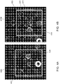
- FIG. 4A is an image 400L of an area 402 of an exemplary tray captured by the left camera 242, according to an embodiment.
- FIG. 4B is an image of an area 403 of an exemplary tray 120 captured by the right camera 244, according to an embodiment.
- the image 400L includes a 3 row x 3 column slot area 402 of the tray 120 including tubes 130.
- the image 400R includes a 3 row x 3 column slot area 403 of the tray 120 including tubes 130.
- the tray grid is aligned at 304.
- the tray 120 may be aligned using fiducial markers disposed on the trays, as described in application entitled "Image-based Tray Alignment and Tube Slot Localization for Drawer Vision System” (Docket No. 2014P22904US).
- the trays may be aligned using determined offsets between projected markers on the trays determined via offline calibration and detected markers on the trays during online operation.
- the method may include steps 306-314 to determine a tray slot type (e.g., whether slot is empty or not empty) and/or steps 316-324 to determine a tube type (e.g., plain tube, tube with a cap or tube with a tube-top sample cup).
- a tray slot type e.g., whether slot is empty or not empty
- steps 316-324 to determine a tube type (e.g., plain tube, tube with a cap or tube with a tube-top sample cup).
- the tray slot patch may be extracted. That is, a plurality of image patches may be extracted over time from each image captured by cameras 242 and 244. Each image patch is substantially centered on one of the tube slots 404 or a top of one of the tubes 130, shown in the images at FIG. 4A and FIG. 4B .
- the tray slot patch may be extracted, as described in application entitled "Image-based Tray Alignment and Tube Slot Localization for Drawer Vision System” (Docket No. 2014P22904US), by projecting tube slot grid points on the trays based on the offset obtained from the tray alignment and using the grid points to extract tube slots from the images.
- FIG. 5 is a diagram illustrating a plurality of image patches grouped into three image patch groups, according to an embodiment.
- the first location group includes a middle patch group 502, a corner patch group 504 and a center patch 506.
- the first location group is based on the camera view perspective.
- the center patch 506 corresponds to one tube slot location, and the middle patch group and corner patch group each corresponds to four tube slot locations.
- the grouping applies to both the left camera 242 and the right camera 244.
- image patch classifiers corresponding to each image patch are trained offline at step 310.
- An exemplary method for training image patch classifiers may include receiving a series of images of a tray having a plurality of tube slots from a plurality of cameras, such as cameras 242 and 244. Image patches may be extracted from each image and fed or provided to a classifier or algorithm.
- Embodiments may include using different types of classifiers, such as for example, a random forest classifier, a support vector machine classifier, and a probabilistic boosting tree classifier.
- Image patch data may be collected, using a processor, for each image patch provided to the classifier.
- the image patch data for each image patch may indicate whether or not each tube slot in the tray contains a tube.
- classifiers may be determined, using the processor, which correspond to each image patch. Methods of classifying are also described in U.S. Application No. 62/010370 to Wu et al.
- a trained classifier is selected for each image patch, based on the middle patch group 502, the corner patch group 504 and the center patch 506.
- the processor may automatically determine whether each tube slot in the tray contains a tube using the selected trained classifier for each image patch based on the three groups 502, 504 and 506.
- steps 316 to 324 to determine a tube type may be performed without first using steps 306 to 314 to determine whether each tube slot in the tray contains a tube.
- steps 316 to steps 324 may be performed under the assumption that each tube slot in the tray contains a tube. The method for determining or predicting a tube type is now described.
- the tube top patch may be extracted. That is, a plurality of image patches may be extracted over time from each image captured by cameras 242 and 244. Each image patch may be substantially centered on a top of one of the tubes 130, shown in the images at FIG. 4A and FIG. 4B .
- the tray slot patch may be extracted, as described in application entitled "Image-based Tube Top Circle Detection for Drawer Vision System” (Docket No. 2014P23281US).
- FIG. 6 is a diagram illustrating a plurality of image patches grouped into six image patch groups, according to an embodiment.
- the second location group includes the center of the image group 506, a left corner of the image group 608, a right corner of the image group 610, a left middle of the image group 602; a center middle of the image group 604 and a right middle of the image group 606.
- the center of the image 506, the left middle of the image group 602 and the right middle of the image group 606 each correspond to one tube top location.
- the center middle of the image group 604, the left corner of the image group 608 and the right corner of the image group 610 each corresponds to two tube slot locations.
- the grouping applies to both the left camera 242 and the right camera 244.
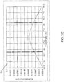
- FIG. 7A is an image 702 illustrating the light distribution of the left camera 242 along with accompanying image data, for use with embodiments described herein.
- FIG. 7B is a diagram 704 illustrating the light distribution along the X-axis of the image 702 shown in FIG. 7A .
- FIG. 7C is a diagram 706 illustrating the light distribution along the Y-axis of the image 702 shown in FIG. 7A .
- the light distribution of the left camera 242 is symmetric along the Y-axis.
- FIG. 7B however, the light distribution of the left camera 242 is asymmetric along the X-axis.
- the grouping of the right camera 244 is horizontally symmetric to that of the left camera 242. Accordingly, the six groups shown in FIG. 6 may be assigned to each image patch extracted from images received from the first camera 242 horizontally symmetric to each image patch extracted from images received from the second camera 244. By assigning the six groups shown in FIG. 6 to each image patch, consistency of the lighting across different patches may be achieved.
- Tubes which appear at each location may be varied and that variation may be learned by the classifiers.
- the same trained classifier may be selected for each image patch extracted from images received from the first camera 242 that is horizontally symmetric to each image patch extracted from images received from the second camera 244.
- the top left patch of the left camera image patches and the top right patch of the right camera image patches are horizontally symmetrical and are part of the same group, the left corner group 608. Accordingly, these two patches may be assigned the same classifier.
- a row of the image patches may be used as a reference location, and other locations may be aligned, via a processor, to the corresponding reference position.
- the alignment can be applied as a vertical or horizontal flip, or a rotation.
- image patch classifiers corresponding to each image patch are trained offline at step 320.
- An exemplary method for training image patch classifiers may be performed as described above with reference to step 310. Methods of classifying are also described in U.S. Application No. 62/010370 to Wu et al.
- a trained classifier is selected for each image patch, based on the six location groups shown in FIG. 6 .
- the processor automatically determines at least one property of each of the tubes contained in the one or more tube slots. For example, determining at least one property of each of the tubes may include automatically determining, from the plurality image patches, whether each of the tubes contained in the one or more tube slots has a cap based on the corresponding trained classifier. Determining at least one property of each of the tubes may include automatically determining, from the plurality image patches, whether each tube contained in the one or more tube slots has a tube-top sample cup or is a plain tube based on the corresponding trained classifier.
- FIG. 8 illustrates an example of a computing environment 800 within which embodiments of the invention may be implemented.
- Computing environment 800 may be implemented as part of any component described herein.
- Computing environment 800 may include computer system 810, which is one example of a computing system upon which embodiments of the invention may be implemented.
- the computer system 810 may include a communication mechanism such as a bus 821 or other communication mechanism for communicating information within the computer system 810.
- the system 810 further includes one or more processors 820 coupled with the bus 821 for processing the information.
- the processors 820 may include one or more CPUs, GPUs, or any other processor known in the art.
- the computer system 810 also includes a system memory 830 coupled to the bus 821 for storing information and instructions to be executed by processors 820.
- the system memory 830 may include computer readable storage media in the form of volatile and/or nonvolatile memory, such as read only memory (ROM) 831 and/or random access memory (RAM) 832.
- the system memory RAM 832 may include other dynamic storage device(s) (e.g., dynamic RAM, static RAM, and synchronous DRAM).
- the system memory ROM 831 may include other static storage device(s) (e.g., programmable ROM, erasable PROM, and electrically erasable PROM).
- the system memory 830 may be used for storing temporary variables or other intermediate information during the execution of instructions by the processors 820.
- a basic input/output system 833 (BIOS) containing the basic routines that help to transfer information between elements within computer system 810, such as during start-up, may be stored in ROM 831.
- RAM 832 may contain data and/or program modules that are immediately accessible to and/or presently being operated on by the processors 820.
- System memory 830 may additionally include, for example, operating system 834, application programs 835, other program modules 836 and program data 837.
- the computer system 810 also includes a disk controller 840 coupled to the bus 821 to control one or more storage devices for storing information and instructions, such as a magnetic hard disk 841 and a removable media drive 842 (e.g., floppy disk drive, compact disc drive, tape drive, and/or solid state drive).
- the storage devices may be added to the computer system 810 using an appropriate device interface (e.g., a small computer system interface (SCSI), integrated device electronics (IDE), Universal Serial Bus (USB), or FireWire).
- SCSI small computer system interface
- IDE integrated device electronics
- USB Universal Serial Bus
- FireWire FireWire
- the computer system 810 may also include a display controller 865 coupled to the bus 821 to control a display or monitor 866, such as a cathode ray tube (CRT) or liquid crystal display (LCD), for displaying information to a computer user.
- the computer system 810 includes a user input interface 860 and one or more input devices, such as a keyboard 862 and a pointing device 861, for interacting with a computer user and providing information to the processor 820.
- the pointing device 861 for example, may be a mouse, a trackball, or a pointing stick for communicating direction information and command selections to the processor 820 and for controlling cursor movement on the display 866.
- the display 866 may provide a touch screen interface which allows input to supplement or replace the communication of direction information and command selections by the pointing device 861.
- the computer system 810 may perform a portion or all of the processing steps of embodiments of the invention in response to the processors 820 executing one or more sequences of one or more instructions contained in a memory, such as the system memory 830.
- a memory such as the system memory 830.
- Such instructions may be read into the system memory 830 from another computer readable medium, such as a hard disk 841 or a removable media drive 842.
- the hard disk 841 may contain one or more data stores and data files used by embodiments of the present invention. Data store contents and data files may be encrypted to improve security.
- the processors 820 may also be employed in a multi-processing arrangement to execute the one or more sequences of instructions contained in system memory 830.
- hard-wired circuitry may be used in place of or in combination with software instructions. Thus, embodiments are not limited to any specific combination of hardware circuitry and software.
- the computer system 810 may include at least one computer readable medium or memory for holding instructions programmed according to embodiments of the invention and for containing data structures, tables, records, or other data described herein.
- the term "computer readable medium” as used herein refers to any non-transitory, tangible medium that participates in providing instructions to the processor 820 for execution.
- a computer readable medium may take many forms including, but not limited to, non-volatile media, volatile media, and transmission media.
- Non-limiting examples of non-volatile media include optical disks, solid state drives, magnetic disks, and magneto-optical disks, such as hard disk 841 or removable media drive 842.
- Non-limiting examples of volatile media include dynamic memory, such as system memory 830.
- Non-limiting examples of transmission media include coaxial cables, copper wire, and fiber optics, including the wires that make up the bus 821.
- Transmission media may also take the form of acoustic or light waves, such as those generated during radio wave and infrared data communications.
- the computing environment 800 may further include the computer system 810 operating in a networked environment using logical connections to one or more remote computers, such as remote computer 880.
- Remote computer 880 may be a personal computer (laptop or desktop), a mobile device, a server, a router, a network PC, a peer device or other common network node, and typically includes many or all of the elements described above relative to computer 810.
- computer 810 may include modem 872 for establishing communications over a network 871, such as the Internet. Modem 872 may be connected to system bus 821 via network interface 870, or via another appropriate mechanism.
- Network 871 may be any network or system generally known in the art, including the Internet, an intranet, a local area network (LAN), a wide area network (WAN), a metropolitan area network (MAN), a direct connection or series of connections, a cellular telephone network, or any other network or medium capable of facilitating communication between computer system 810 and other computers (e.g., remote computing system 880).
- the network 871 may be wired, wireless or a combination thereof. Wired connections may be implemented using Ethernet, Universal Serial Bus (USB), RJ-11 or any other wired connection generally known in the art.
- Wireless connections may be implemented using Wi-Fi, WiMAX, and Bluetooth, infrared, cellular networks, satellite or any other wireless connection methodology generally known in the art. Additionally, several networks may work alone or in communication with each other to facilitate communication in the network 871.
- a processor as used herein is a device for executing machine-readable instructions stored on a computer readable medium, for performing tasks and may comprise any one or combination of, hardware and firmware.
- a processor may also comprise memory storing machine-readable instructions executable for performing tasks.
- a processor acts upon information by manipulating, analyzing, modifying, converting or transmitting information for use by an executable procedure or an information device, and/or by routing the information to an output device.
- a processor may use or comprise the capabilities of a computer, controller or microprocessor, for example, and is conditioned using executable instructions to perform special purpose functions not performed by a general purpose computer.
- a processor may be coupled (electrically and/or as comprising executable components) with any other processor enabling interaction and/or communication therebetween.
- Computer program instructions may be loaded onto a computer, including without limitation, a general purpose computer or special purpose computer, or other programmable processing apparatus to produce a machine, such that the computer program instructions which execute on the computer or other programmable processing apparatus create means for implementing the functions specified in the block(s) of the flowchart(s).
- a user interface processor or generator is a known element comprising electronic circuitry or software or a combination of both for generating display elements or portions thereof.
- a user interface (UI) comprises one or more display elements enabling user interaction with a processor or other device.
- An executable application comprises code or machine readable instructions for conditioning the processor to implement predetermined functions, such as those of an operating system, a context data acquisition system or other information processing system, for example, in response to user command or input.
- An executable procedure is a segment of code or machine readable instruction, sub-routine, or other distinct section of code or portion of an executable application for performing one or more particular processes. These processes may include receiving input data and/or parameters, performing operations on received input data and/or performing functions in response to received input parameters, and providing resulting output data and/or parameters.
- GUI graphical user interface
- GUI comprises one or more display elements, generated by a display processor and enabling user interaction with a processor or other device and associated data acquisition and processing functions.
- the UI also includes an executable procedure or executable application.
- the executable procedure or executable application conditions the display processor to generate signals representing the UI display images. These signals are supplied to a display device which displays the elements for viewing by the user.
- the executable procedure or executable application further receives signals from user input devices, such as a keyboard, mouse, light pen, touch screen or any other means allowing a user to provide data to a processor.
- the processor under control of an executable procedure or executable application, manipulates the UI display elements in response to signals received from the input devices. In this way, the user interacts with the display elements using the input devices, enabling user interaction with the processor or other device.
- the functions and process steps herein may be performed automatically or wholly or partially in response to user command. An activity (including a step) performed automatically is performed in response to executable instruction or device operation without user direct initiation of the activity.
- a workflow processor processes data to determine tasks to add to, or remove from, a task list or modifies tasks incorporated on, or for incorporation on, a task list, as for example specified in a program(s).
- a task list is a list of tasks for performance by a worker, user of a device, or device or a combination of both.
- a workflow processor may or may not employ a workflow engine.
- a workflow engine is a processor executing in response to predetermined process definitions that implement processes responsive to events and event associated data. The workflow engine implements processes in sequence and/or concurrently, responsive to event associated data to determine tasks for performance by a device and or worker and for updating task lists of a device and a worker to include determined tasks.
- a process definition is definable by a user and comprises a sequence of process steps including one or more, of start, wait, decision and task allocation steps for performance by a device and or worker, for example.
- An event is an occurrence affecting operation of a process implemented using a process definition.
- the workflow engine includes a process definition function that allows users to define a process that is to be followed and may include an event monitor.
- a processor in the workflow engine tracks which processes are running, for which patients, physicians, and what step needs to be executed next, according to a process definition and may include a procedure for notifying physicians of a task to be performed.
Claims (10)
- Procédé pour détecter les propriétés de tubes d'échantillon dans un plateau, le plateau comprenant une pluralité de fentes de tube (404) disposées dans une matrice de rangées et de colonnes, chaque fente de tube (404) étant configurée pour recevoir un tube échantillon, comprenant les étapes consistant à :recevoir une série d'images du plateau acquises par une ou plusieurs caméras (242, 244), dans lequel chaque image comprend une matrice de trois rangées de fentes de tube (404) et trois colonnes de fentes de tube (404) ;extraire, à l'aide d'un processeur, une pluralité de régions d'image à partir de chaque image,où chacune de la pluralité de régions d'image est sensiblement centrée sur un élément parmi une fente de tube (404) ou un sommet de tube (130) et comprend une matrice de trois rangées de régions d'image et de trois colonnes de régions d'image et chaque région d'image correspond à un emplacement d'une des fentes de tube (404) dans l'image ;affecter, à chaque région d'image, un premier groupe d'emplacement comprenant un groupe de région milieu (502), un groupe de région de coin (504) et un groupe de région centre (506) qui définit si le région d'image provient de l'un des éléments suivants : un centre de l'image, un coin de l'image et un bord centre de l'image ;sélectionner pour chaque région d'image, en fonction du premier groupe d'emplacements, un classificateur formé à utiliser pour le traitement de la région d'image ;déterminer automatiquement, à l'aide du processeur, à partir de la pluralité de régions d'image, si chaque fente de tube (404) dans le plateau contient un tube en utilisant le classificateur formé pour chaque région d'image,et comprenant en outre les étapes consistant à :affecter à chaque région d'image, un second groupe d'emplacement comprenant le centre d'un groupe d'images (506), un coin gauche d'un groupe d'images (608), un coin droit d'un groupe d'images (610), un milieu gauche d'un groupe d'images (602), un milieu centre d'un groupe d'images (604) et un milieu droit d'un groupe d'images (606) qui détermine si la région d'image est issue : du centre de l'image, d'un coin gauche de l'image, d'un coin droit de l'image, d'un milieu gauche de l'image, d'un milieu centre de l'image et d'un milieu droit de l'image ; etsélectionner pour chaque région d'image, en fonction du second groupe d'emplacement, un classificateur formé à utiliser pour le traitement de la région d'image,où, lorsqu'il est déterminé qu'une ou plusieurs des fentes de tube (404) contiennent un tube, le procédé comprend en outre la détermination automatique, en utilisant le processeur, à partir de la pluralité de régions d'image, d'au moins une propriété de chacun des tubes contenus dans la ou les fentes de tube (404).
- Procédé selon la revendication 1, dans lequel le plateau est configuré pour s'adapter à une partie d'un tiroir (110) mobile entre une position ouverte et une position fermée et la série d'images du plateau est acquise via la ou les caméras (242, 244) lorsque le tiroir (110) est déplacé entre les positions ouverte et fermée.
- Procédé selon la revendication 1, dans lequel la détermination d'au moins une propriété de chacun des tubes comprend en outre la détermination automatique, à l'aide du processeur, à partir de la pluralité de régions d'image, si chacun des tubes contenus dans la ou les fentes de tube (404) a un bouchon basé sur le classificateur formé correspondant, ou a un récipient d'échantillon de sommet de tube ou est un tube lisse basé sur le classificateur formé correspondant.
- Procédé selon la revendication 1, dans lequel
la réception de la série d'images comprend en outre la réception de la série d'images d'une première caméra (242) et d'une seconde caméra (244) adjacentes à la première caméra,
l'extraction de la pluralité de régions d'image comprend en outre l'extraction de régions d'image de chaque image reçue de la première caméra (242) et l'extraction de régions d'image de chaque image reçue de la seconde caméra (244),
l'affectation du second groupe d'emplacement comprend en outre l'affectation du second groupe d'emplacement à chaque région d'image extraite d'images reçues de la première caméra (242) symétriquement horizontalement à chaque région d'image extraite d'images reçues de la seconde caméra (244), et
la sélection du classificateur formé comprend en outre la sélection du même classificateur formé pour chaque région d'image extraite d'images reçues de la première caméra (242) qui est symétrique horizontalement à chaque région d'image extraite d'images reçues de la seconde caméra (244). - Procédé selon la revendication 4, dans lequel le coin gauche de l'image, le coin droit de l'image et le milieu centre de l'image comprennent chacun une pluralité de régions d'image, et
l'affectation du second groupe d'emplacement à symétrie horizontale comprend en outre :l'utilisation d'une rangée de régions d'image provenant de l'une de la première caméra (242) et de la seconde caméra (244) comme emplacement de référence ; etl'alignement des régions d'image de l'autre de la première caméra (242) et de la seconde caméra (244) à l'emplacement de référence. - Système de vision destiné à être utilisé dans un environnement de diagnostic in vitro comprenant :un plateau comprenant une pluralité de fentes (404) disposées dans une matrice de rangées et de colonnes, chaque fente de tube (404) étant configurée pour recevoir un tube échantillon ;une surface configurée pour recevoir le plateau ;un système de capture d'image ayant une première caméra (242) configurée pour capturer une série d'images du plateau, dans lequel chaque image comprend une matrice de trois rangées de fentes de tube (404) et trois colonnes de fentes de tube (404) ; etun processeur configuré pour :recevoir la série d'images du plateau capturées par la première caméra (242) ;extraire une pluralité de régions d'image de chaque image de la série d'images,où chacune de la pluralité de régions d'image est sensiblement centrée sur l'une de la pluralité de fentes de tube (404) ou sur un sommet de tube (130) et comprend une matrice de trois rangées de régions d'image et trois colonnes de régions d'image, chaque région d'image correspondant à un emplacement d'une des fentes de tube (404) sur l'image ;assigner, à chaque région d'image, un premier groupe d'emplacements comprenant un groupe de régions de milieu (502), un groupe de région de coin (504) et un groupe de régions centres (506) qui définit si la région d'image provient de l'un des éléments suivants : le centre de l'image, un coin de l'image, et un bord centre de l'image ;sélectionner, pour chaque région d'image, en fonction du premier groupe d'emplacement, un classificateur formé à utiliser pour traiter la région d'image ; etdéterminer automatiquement, à partir de la pluralité de régions d'image, si chaque fente de tube (404) dans le plateau contient un tube échantillon correspondant en utilisant le classificateur formé pour chaque région d'image,où le processeur est en outre configuré pour :affecter, à chaque région d'image, un second groupe d'emplacement comprenant le centre d'un groupe d'images (506), un coin gauche d'un groupe d'images (608), un coin droit d'un groupe d'images (610), un milieu gauche d'un groupe d'images (602), un milieu centre d'un groupe d'images (604) et un milieu droit d'un groupe d'images (606) qui détermine si la région d'image est à partir de l'un parmi : le centre de l'image, un coin gauche de l'image, un coin droit de l'image et un milieu gauche de l'image, un milieu centre de l'image et un milieu droit de l'image ;sélectionner, pour chaque région d'image, en fonction du second groupe d'emplacement, un classificateur formé à utiliser pour traiter la région d'image, etlorsqu'il est déterminé que la ou les fentes de tube (404) contiennent un tube, déterminer automatiquement, à partir de la pluralité de régions d'image, au moins une propriété de chacun des tubes contenus dans la ou les fentes de tube (404), etdéterminer automatiquement, à partir de la pluralité de régions d'image, si chacun des tubes contenus dans la ou les fentes de tube (404) a un bouchon basé sur le classificateur formé correspondant, etdéterminer automatiquement, à partir de la pluralité de régions d'image, si chaque tube contenu dans la ou les fentes de tube (404) possède un récipient d'échantillon de sommet de tube ou est un tube lisse basé sur le classificateur formé correspondant.
- Système selon la revendication 6, dans lequel le système de capture d'image comprend en outre une seconde caméra (244) adjacente à la première caméra et configurée pour capturer des images du plateau à proximité des images capturées par la première caméra (242),
et
dans laquelle la surface comprend une partie d'un tiroir (110) mobile entre une position ouverte et une position fermée et l'image du plateau est capturée via la première caméra (242) et la seconde caméra (244) lorsque le tiroir (110) est déplacé entre la position ouverte et la position fermée. - Système selon la revendication 7, dans lequel le processeur est en outre configuré pour :extraire des régions d'image de chaque image reçue de la première caméra (242) et extraire des régions d'image de chaque image reçue de la seconde caméra (244) ;affecter le second groupe d'emplacement à chaque région d'image extraite d'images reçues de la première caméra (242) symétrique horizontalement à chaque région d'image extraite d'images reçues de la seconde caméra (244) ; etsélectionner le même classificateur formé pour chaque région d'image extraite d'images reçues de la première caméra (242) qui est symétrique horizontalement à chaque région d'image extraite d'images reçues de la seconde caméra (244).
- Système selon la revendication 7, dans lequel le coin gauche de l'image, le coin droit de l'image et le milieu centre de l'image comprennent chacun une pluralité de régions d'image, et
le processeur est en outre configuré pour affecter le second groupe d'emplacement à chaque région d'image extraite d'images reçues de la première caméra (242) symétrique horizontalement à chaque région d'image extraite d'images reçues de la seconde caméra (244) par :l'utilisation d'une rangée de régions d'image provenant de l'une de la première caméra (242) et de la seconde caméra (244) comme emplacement de référence ; etl'alignement des régions d'image de l'autre de la première caméra (242) et de la seconde caméra (244) à l'emplacement de référence. - Système selon la revendication 7, dans lequel le système de capture d'image comprend en outre une carte à diode électroluminescente (DEL) comprenant :un premier trou configuré pour faciliter la capture de la série d'images du plateau à partir de la première caméra (242) ;un seconde trou configuré pour faciliter la capture de la série d'images du plateau à partir de la seconde caméra (244) ; etune pluralité de DEL disposées de manière circulaire autour de chacun des premier et seconde trous et configurées pour fournir de la lumière sur le plateau.
Applications Claiming Priority (2)
| Application Number | Priority Date | Filing Date | Title |
|---|---|---|---|
| US201562117916P | 2015-02-18 | 2015-02-18 | |
| PCT/US2016/018112 WO2016133926A1 (fr) | 2015-02-18 | 2016-02-16 | Détection basée sur la localisation de types de fentes de plateau et de types de tubes dans un système de vision |
Publications (3)
| Publication Number | Publication Date |
|---|---|
| EP3259737A1 EP3259737A1 (fr) | 2017-12-27 |
| EP3259737A4 EP3259737A4 (fr) | 2018-03-28 |
| EP3259737B1 true EP3259737B1 (fr) | 2020-04-15 |
Family
ID=56689145
Family Applications (1)
| Application Number | Title | Priority Date | Filing Date |
|---|---|---|---|
| EP16752922.1A Active EP3259737B1 (fr) | 2015-02-18 | 2016-02-16 | Détection basée sur la localisation de types de fentes de plateau et de types de tubes dans un système de vision |
Country Status (7)
| Country | Link |
|---|---|
| US (1) | US10319092B2 (fr) |
| EP (1) | EP3259737B1 (fr) |
| JP (1) | JP6718465B2 (fr) |
| CN (1) | CN107615336B (fr) |
| CA (1) | CA2976947C (fr) |
| HK (1) | HK1244577A1 (fr) |
| WO (1) | WO2016133926A1 (fr) |
Families Citing this family (11)
| Publication number | Priority date | Publication date | Assignee | Title |
|---|---|---|---|---|
| WO2016133926A1 (fr) * | 2015-02-18 | 2016-08-25 | Siemens Healthcare Diagnostics Inc. | Détection basée sur la localisation de types de fentes de plateau et de types de tubes dans un système de vision |
| CN109414826B (zh) | 2016-07-14 | 2022-02-22 | 西门子医疗保健诊断公司 | 用于基于样品架成像数据的动态拾取和放置选择顺序的方法、系统和装置 |
| US11241788B2 (en) | 2016-07-14 | 2022-02-08 | Siemens Healthcare Diagnostics Inc. | Methods and apparatus for dynamic position adjustments of a robot gripper based on sample rack imaging data |
| KR102586862B1 (ko) | 2016-10-28 | 2023-10-11 | 베크만 컬터, 인코포레이티드 | 물질 준비 평가 시스템 |
| CN207215844U (zh) * | 2017-08-22 | 2018-04-10 | 深圳市帝迈生物技术有限公司 | 自动进样血液分析仪及其试管自动进样识别装置 |
| US10740585B2 (en) * | 2018-12-12 | 2020-08-11 | General Electric Technology Gmbh | System and apparatus for identifying boiler tubes |
| WO2021086725A1 (fr) * | 2019-10-31 | 2021-05-06 | Siemens Healthcare Diagnostics Inc. | Appareil et procédés d'entraînement de modèles d'analyseurs de diagnostic |
| EP3901633B1 (fr) | 2020-04-22 | 2022-08-17 | Roche Diagnostics GmbH | Système de distribution de récipients d'échantillons de laboratoire, procédé de fonctionnement et système de diagnostic in vitro |
| EP3979131A1 (fr) * | 2020-10-02 | 2022-04-06 | Roche Diagnostics GmbH | Procédé permettant de déterminer au moins un état d'au moins une cavité d'une interface de transport conçue pour transporter des tubes d'échantillons |
| CN113477291B (zh) * | 2021-05-21 | 2022-07-01 | 遵义医科大学 | 一种带标尺和摄像功能的新型实验托盘 |
| WO2023088600A1 (fr) | 2021-11-22 | 2023-05-25 | Roche Diagnostics Gmbh | Procédé et système pour faire fonctionner un système d'automatisation de laboratoire |
Family Cites Families (18)
| Publication number | Priority date | Publication date | Assignee | Title |
|---|---|---|---|---|
| FR2635897B1 (fr) * | 1988-08-29 | 1990-11-30 | Edelist Richard | Boite a comparaison, universelle, destinee au domaine sensoriel |
| ATE450834T1 (de) * | 2001-01-23 | 2009-12-15 | Health Discovery Corp | Rechnergestützte bildanalyse |
| AU2003235627A1 (en) * | 2002-01-19 | 2003-07-30 | Pvt Probenverteiltechnik Gmbh | Method and device for the analysis of body fluids |
| JP5211486B2 (ja) * | 2007-01-19 | 2013-06-12 | 日本電気株式会社 | 化合物の仮想スクリーニング方法及び装置 |
| US8131065B2 (en) * | 2007-12-20 | 2012-03-06 | Intel Corporation | Method and apparatus for obtaining and processing image features |
| JP5253194B2 (ja) * | 2009-01-20 | 2013-07-31 | セコム株式会社 | 物体検出装置 |
| JP5534840B2 (ja) * | 2010-02-03 | 2014-07-02 | キヤノン株式会社 | 画像処理装置、画像処理方法、画像処理システム及びプログラム |
| GB201009798D0 (en) * | 2010-06-11 | 2010-07-21 | Immunovia Ab | Method,array and use thereof |
| EP2686830B1 (fr) | 2011-03-15 | 2015-01-21 | Siemens Healthcare Diagnostics Inc. | Systèmes et procédés stéréoscopiques multi-vues pour un inventaire de tube dans des diagnostics de soins de santé |
| WO2013070756A2 (fr) * | 2011-11-07 | 2013-05-16 | Beckman Coulter, Inc. | Système et procédé de traitement d'échantillons |
| CN203083855U (zh) * | 2012-11-07 | 2013-07-24 | 贝克曼考尔特公司 | 用于自动处理样品的设备 |
| US9528915B2 (en) * | 2012-11-13 | 2016-12-27 | Ues, Inc. | Automated high speed metallographic system |
| US10145857B2 (en) * | 2013-03-14 | 2018-12-04 | Siemens Healthcare Diagnostics Inc. | Tube tray vision system |
| JP6217446B2 (ja) * | 2013-06-28 | 2017-10-25 | 株式会社Jvcケンウッド | 制御装置、診断支援装置、制御方法及び制御プログラム |
| CN107003124B (zh) | 2014-06-10 | 2020-07-07 | 西门子医疗保健诊断公司 | 抽屉视觉系统 |
| CN203935367U (zh) * | 2014-06-24 | 2014-11-12 | 湖州市中心医院 | 一种多功能安全卫生托盘 |
| CN104165896B (zh) * | 2014-08-18 | 2017-03-22 | 公安部第一研究所 | 一种液态物品安全检查的方法与装置 |
| WO2016133926A1 (fr) * | 2015-02-18 | 2016-08-25 | Siemens Healthcare Diagnostics Inc. | Détection basée sur la localisation de types de fentes de plateau et de types de tubes dans un système de vision |
-
2016
- 2016-02-16 WO PCT/US2016/018112 patent/WO2016133926A1/fr active Application Filing
- 2016-02-16 US US15/551,571 patent/US10319092B2/en active Active
- 2016-02-16 CN CN201680022459.9A patent/CN107615336B/zh active Active
- 2016-02-16 CA CA2976947A patent/CA2976947C/fr active Active
- 2016-02-16 EP EP16752922.1A patent/EP3259737B1/fr active Active
- 2016-02-16 JP JP2017543749A patent/JP6718465B2/ja active Active
-
2018
- 2018-03-06 HK HK18103151.9A patent/HK1244577A1/zh unknown
Non-Patent Citations (1)
| Title |
|---|
| None * |
Also Published As
| Publication number | Publication date |
|---|---|
| WO2016133926A1 (fr) | 2016-08-25 |
| EP3259737A4 (fr) | 2018-03-28 |
| CN107615336A (zh) | 2018-01-19 |
| EP3259737A1 (fr) | 2017-12-27 |
| US10319092B2 (en) | 2019-06-11 |
| US20180033140A1 (en) | 2018-02-01 |
| JP2018507482A (ja) | 2018-03-15 |
| CA2976947A1 (fr) | 2016-08-25 |
| HK1244577A1 (zh) | 2018-08-10 |
| CN107615336B (zh) | 2021-10-15 |
| JP6718465B2 (ja) | 2020-07-08 |
| CA2976947C (fr) | 2023-02-28 |
Similar Documents
| Publication | Publication Date | Title |
|---|---|---|
| EP3259737B1 (fr) | Détection basée sur la localisation de types de fentes de plateau et de types de tubes dans un système de vision | |
| US10290090B2 (en) | Image-based tube slot circle detection for a vision system | |
| JP6960980B2 (ja) | 視覚システムにおける画像ベーストレイ位置合わせ及びチューブスロット位置特定 | |
| US11847751B2 (en) | Method and system for implementing augmented reality (AR)-based assistance within work environment | |
| JP6975474B2 (ja) | 空気試料の自動分析を実行するためのシステム及び方法 | |
| JP6735655B2 (ja) | 電子検査室ジャーナルへの入力情報を生成するための方法 | |
| Fisher et al. | SynchWeb: a modern interface for ISPyB | |
| Oscarsson et al. | MXCuBE2: the dawn of MXCuBE Collaboration | |
| CN109817322A (zh) | 用于定位手持式分析设备的方法和系统 | |
| CN104508576A (zh) | 工业工厂中的对象检验 | |
| EP3652674B1 (fr) | Détection de cercles de sommet de tubes basée sur des images avec candidats multiples | |
| Pantanowitz | Automated pap tests | |
| CN114364986A (zh) | 远程样品递送系统 |
Legal Events
| Date | Code | Title | Description |
|---|---|---|---|
| STAA | Information on the status of an ep patent application or granted ep patent |
Free format text: STATUS: THE INTERNATIONAL PUBLICATION HAS BEEN MADE |
|
| PUAI | Public reference made under article 153(3) epc to a published international application that has entered the european phase |
Free format text: ORIGINAL CODE: 0009012 |
|
| STAA | Information on the status of an ep patent application or granted ep patent |
Free format text: STATUS: REQUEST FOR EXAMINATION WAS MADE |
|
| 17P | Request for examination filed |
Effective date: 20170918 |
|
| AK | Designated contracting states |
Kind code of ref document: A1 Designated state(s): AL AT BE BG CH CY CZ DE DK EE ES FI FR GB GR HR HU IE IS IT LI LT LU LV MC MK MT NL NO PL PT RO RS SE SI SK SM TR |
|
| AX | Request for extension of the european patent |
Extension state: BA ME |
|
| RIN1 | Information on inventor provided before grant (corrected) |
Inventor name: WU, WEN Inventor name: POLLACK, BENJAMIN Inventor name: DUMONT, GUILLAUME Inventor name: CHANG, YAO-JEN Inventor name: CHEN, TERRENCE |
|
| A4 | Supplementary search report drawn up and despatched |
Effective date: 20180222 |
|
| RIC1 | Information provided on ipc code assigned before grant |
Ipc: G01N 1/28 20060101ALI20180217BHEP Ipc: G01N 35/00 20060101ALI20180217BHEP Ipc: G01N 35/04 20060101ALN20180217BHEP Ipc: G06T 7/12 20170101AFI20180217BHEP Ipc: G06T 7/60 20170101ALI20180217BHEP |
|
| DAV | Request for validation of the european patent (deleted) | ||
| DAX | Request for extension of the european patent (deleted) | ||
| STAA | Information on the status of an ep patent application or granted ep patent |
Free format text: STATUS: EXAMINATION IS IN PROGRESS |
|
| 17Q | First examination report despatched |
Effective date: 20181015 |
|
| REG | Reference to a national code |
Ref country code: DE Ref legal event code: R079 Ref document number: 602016034091 Country of ref document: DE Free format text: PREVIOUS MAIN CLASS: G06T0007600000 Ipc: G06T0007120000 |
|
| RIC1 | Information provided on ipc code assigned before grant |
Ipc: G01N 35/04 20060101ALN20190823BHEP Ipc: G01N 35/00 20060101ALI20190823BHEP Ipc: G01N 1/28 20060101ALI20190823BHEP Ipc: G06T 7/60 20170101ALI20190823BHEP Ipc: G06T 7/12 20170101AFI20190823BHEP |
|
| RIC1 | Information provided on ipc code assigned before grant |
Ipc: G06T 7/60 20170101ALI20190925BHEP Ipc: G01N 1/28 20060101ALI20190925BHEP Ipc: G01N 35/00 20060101ALI20190925BHEP Ipc: G01N 35/04 20060101ALN20190925BHEP Ipc: G06T 7/12 20170101AFI20190925BHEP |
|
| GRAJ | Information related to disapproval of communication of intention to grant by the applicant or resumption of examination proceedings by the epo deleted |
Free format text: ORIGINAL CODE: EPIDOSDIGR1 |
|
| STAA | Information on the status of an ep patent application or granted ep patent |
Free format text: STATUS: GRANT OF PATENT IS INTENDED |
|
| GRAP | Despatch of communication of intention to grant a patent |
Free format text: ORIGINAL CODE: EPIDOSNIGR1 |
|
| INTG | Intention to grant announced |
Effective date: 20191112 |
|
| RIN1 | Information on inventor provided before grant (corrected) |
Inventor name: POLLACK, BENJAMIN Inventor name: CHEN, TERRENCE Inventor name: CHANG, YAO-JEN Inventor name: DUMONT, GUILLAUME Inventor name: WU, WEN |
|
| GRAS | Grant fee paid |
Free format text: ORIGINAL CODE: EPIDOSNIGR3 |
|
| GRAA | (expected) grant |
Free format text: ORIGINAL CODE: 0009210 |
|
| STAA | Information on the status of an ep patent application or granted ep patent |
Free format text: STATUS: THE PATENT HAS BEEN GRANTED |
|
| AK | Designated contracting states |
Kind code of ref document: B1 Designated state(s): AL AT BE BG CH CY CZ DE DK EE ES FI FR GB GR HR HU IE IS IT LI LT LU LV MC MK MT NL NO PL PT RO RS SE SI SK SM TR |
|
| REG | Reference to a national code |
Ref country code: CH Ref legal event code: EP |
|
| REG | Reference to a national code |
Ref country code: DE Ref legal event code: R096 Ref document number: 602016034091 Country of ref document: DE |
|
| REG | Reference to a national code |
Ref country code: IE Ref legal event code: FG4D |
|
| REG | Reference to a national code |
Ref country code: AT Ref legal event code: REF Ref document number: 1258167 Country of ref document: AT Kind code of ref document: T Effective date: 20200515 |
|
| REG | Reference to a national code |
Ref country code: NL Ref legal event code: MP Effective date: 20200415 |
|
| REG | Reference to a national code |
Ref country code: LT Ref legal event code: MG4D |
|
| PG25 | Lapsed in a contracting state [announced via postgrant information from national office to epo] |
Ref country code: NO Free format text: LAPSE BECAUSE OF FAILURE TO SUBMIT A TRANSLATION OF THE DESCRIPTION OR TO PAY THE FEE WITHIN THE PRESCRIBED TIME-LIMIT Effective date: 20200715 Ref country code: SE Free format text: LAPSE BECAUSE OF FAILURE TO SUBMIT A TRANSLATION OF THE DESCRIPTION OR TO PAY THE FEE WITHIN THE PRESCRIBED TIME-LIMIT Effective date: 20200415 Ref country code: GR Free format text: LAPSE BECAUSE OF FAILURE TO SUBMIT A TRANSLATION OF THE DESCRIPTION OR TO PAY THE FEE WITHIN THE PRESCRIBED TIME-LIMIT Effective date: 20200716 Ref country code: IS Free format text: LAPSE BECAUSE OF FAILURE TO SUBMIT A TRANSLATION OF THE DESCRIPTION OR TO PAY THE FEE WITHIN THE PRESCRIBED TIME-LIMIT Effective date: 20200815 Ref country code: FI Free format text: LAPSE BECAUSE OF FAILURE TO SUBMIT A TRANSLATION OF THE DESCRIPTION OR TO PAY THE FEE WITHIN THE PRESCRIBED TIME-LIMIT Effective date: 20200415 Ref country code: LT Free format text: LAPSE BECAUSE OF FAILURE TO SUBMIT A TRANSLATION OF THE DESCRIPTION OR TO PAY THE FEE WITHIN THE PRESCRIBED TIME-LIMIT Effective date: 20200415 Ref country code: PT Free format text: LAPSE BECAUSE OF FAILURE TO SUBMIT A TRANSLATION OF THE DESCRIPTION OR TO PAY THE FEE WITHIN THE PRESCRIBED TIME-LIMIT Effective date: 20200817 Ref country code: NL Free format text: LAPSE BECAUSE OF FAILURE TO SUBMIT A TRANSLATION OF THE DESCRIPTION OR TO PAY THE FEE WITHIN THE PRESCRIBED TIME-LIMIT Effective date: 20200415 |
|
| REG | Reference to a national code |
Ref country code: AT Ref legal event code: MK05 Ref document number: 1258167 Country of ref document: AT Kind code of ref document: T Effective date: 20200415 |
|
| PG25 | Lapsed in a contracting state [announced via postgrant information from national office to epo] |
Ref country code: LV Free format text: LAPSE BECAUSE OF FAILURE TO SUBMIT A TRANSLATION OF THE DESCRIPTION OR TO PAY THE FEE WITHIN THE PRESCRIBED TIME-LIMIT Effective date: 20200415 Ref country code: RS Free format text: LAPSE BECAUSE OF FAILURE TO SUBMIT A TRANSLATION OF THE DESCRIPTION OR TO PAY THE FEE WITHIN THE PRESCRIBED TIME-LIMIT Effective date: 20200415 Ref country code: HR Free format text: LAPSE BECAUSE OF FAILURE TO SUBMIT A TRANSLATION OF THE DESCRIPTION OR TO PAY THE FEE WITHIN THE PRESCRIBED TIME-LIMIT Effective date: 20200415 Ref country code: BG Free format text: LAPSE BECAUSE OF FAILURE TO SUBMIT A TRANSLATION OF THE DESCRIPTION OR TO PAY THE FEE WITHIN THE PRESCRIBED TIME-LIMIT Effective date: 20200715 |
|
| PG25 | Lapsed in a contracting state [announced via postgrant information from national office to epo] |
Ref country code: AL Free format text: LAPSE BECAUSE OF FAILURE TO SUBMIT A TRANSLATION OF THE DESCRIPTION OR TO PAY THE FEE WITHIN THE PRESCRIBED TIME-LIMIT Effective date: 20200415 |
|
| REG | Reference to a national code |
Ref country code: DE Ref legal event code: R097 Ref document number: 602016034091 Country of ref document: DE |
|
| PG25 | Lapsed in a contracting state [announced via postgrant information from national office to epo] |
Ref country code: IT Free format text: LAPSE BECAUSE OF FAILURE TO SUBMIT A TRANSLATION OF THE DESCRIPTION OR TO PAY THE FEE WITHIN THE PRESCRIBED TIME-LIMIT Effective date: 20200415 Ref country code: RO Free format text: LAPSE BECAUSE OF FAILURE TO SUBMIT A TRANSLATION OF THE DESCRIPTION OR TO PAY THE FEE WITHIN THE PRESCRIBED TIME-LIMIT Effective date: 20200415 Ref country code: CZ Free format text: LAPSE BECAUSE OF FAILURE TO SUBMIT A TRANSLATION OF THE DESCRIPTION OR TO PAY THE FEE WITHIN THE PRESCRIBED TIME-LIMIT Effective date: 20200415 Ref country code: ES Free format text: LAPSE BECAUSE OF FAILURE TO SUBMIT A TRANSLATION OF THE DESCRIPTION OR TO PAY THE FEE WITHIN THE PRESCRIBED TIME-LIMIT Effective date: 20200415 Ref country code: SM Free format text: LAPSE BECAUSE OF FAILURE TO SUBMIT A TRANSLATION OF THE DESCRIPTION OR TO PAY THE FEE WITHIN THE PRESCRIBED TIME-LIMIT Effective date: 20200415 Ref country code: AT Free format text: LAPSE BECAUSE OF FAILURE TO SUBMIT A TRANSLATION OF THE DESCRIPTION OR TO PAY THE FEE WITHIN THE PRESCRIBED TIME-LIMIT Effective date: 20200415 Ref country code: DK Free format text: LAPSE BECAUSE OF FAILURE TO SUBMIT A TRANSLATION OF THE DESCRIPTION OR TO PAY THE FEE WITHIN THE PRESCRIBED TIME-LIMIT Effective date: 20200415 Ref country code: EE Free format text: LAPSE BECAUSE OF FAILURE TO SUBMIT A TRANSLATION OF THE DESCRIPTION OR TO PAY THE FEE WITHIN THE PRESCRIBED TIME-LIMIT Effective date: 20200415 |
|
| PLBE | No opposition filed within time limit |
Free format text: ORIGINAL CODE: 0009261 |
|
| STAA | Information on the status of an ep patent application or granted ep patent |
Free format text: STATUS: NO OPPOSITION FILED WITHIN TIME LIMIT |
|
| PG25 | Lapsed in a contracting state [announced via postgrant information from national office to epo] |
Ref country code: SK Free format text: LAPSE BECAUSE OF FAILURE TO SUBMIT A TRANSLATION OF THE DESCRIPTION OR TO PAY THE FEE WITHIN THE PRESCRIBED TIME-LIMIT Effective date: 20200415 Ref country code: PL Free format text: LAPSE BECAUSE OF FAILURE TO SUBMIT A TRANSLATION OF THE DESCRIPTION OR TO PAY THE FEE WITHIN THE PRESCRIBED TIME-LIMIT Effective date: 20200415 |
|
| 26N | No opposition filed |
Effective date: 20210118 |
|
| PG25 | Lapsed in a contracting state [announced via postgrant information from national office to epo] |
Ref country code: SI Free format text: LAPSE BECAUSE OF FAILURE TO SUBMIT A TRANSLATION OF THE DESCRIPTION OR TO PAY THE FEE WITHIN THE PRESCRIBED TIME-LIMIT Effective date: 20200415 |
|
| PG25 | Lapsed in a contracting state [announced via postgrant information from national office to epo] |
Ref country code: MC Free format text: LAPSE BECAUSE OF FAILURE TO SUBMIT A TRANSLATION OF THE DESCRIPTION OR TO PAY THE FEE WITHIN THE PRESCRIBED TIME-LIMIT Effective date: 20200415 |
|
| GBPC | Gb: european patent ceased through non-payment of renewal fee |
Effective date: 20210216 |
|
| REG | Reference to a national code |
Ref country code: BE Ref legal event code: MM Effective date: 20210228 |
|
| PG25 | Lapsed in a contracting state [announced via postgrant information from national office to epo] |
Ref country code: CH Free format text: LAPSE BECAUSE OF NON-PAYMENT OF DUE FEES Effective date: 20210228 Ref country code: LI Free format text: LAPSE BECAUSE OF NON-PAYMENT OF DUE FEES Effective date: 20210228 Ref country code: LU Free format text: LAPSE BECAUSE OF NON-PAYMENT OF DUE FEES Effective date: 20210216 |
|
| PG25 | Lapsed in a contracting state [announced via postgrant information from national office to epo] |
Ref country code: GB Free format text: LAPSE BECAUSE OF NON-PAYMENT OF DUE FEES Effective date: 20210216 Ref country code: FR Free format text: LAPSE BECAUSE OF NON-PAYMENT OF DUE FEES Effective date: 20210228 Ref country code: IE Free format text: LAPSE BECAUSE OF NON-PAYMENT OF DUE FEES Effective date: 20210216 |
|
| PG25 | Lapsed in a contracting state [announced via postgrant information from national office to epo] |
Ref country code: BE Free format text: LAPSE BECAUSE OF NON-PAYMENT OF DUE FEES Effective date: 20210228 |
|
| PGFP | Annual fee paid to national office [announced via postgrant information from national office to epo] |
Ref country code: DE Payment date: 20220620 Year of fee payment: 8 |
|
| PG25 | Lapsed in a contracting state [announced via postgrant information from national office to epo] |
Ref country code: CY Free format text: LAPSE BECAUSE OF FAILURE TO SUBMIT A TRANSLATION OF THE DESCRIPTION OR TO PAY THE FEE WITHIN THE PRESCRIBED TIME-LIMIT Effective date: 20200415 |
|
| PG25 | Lapsed in a contracting state [announced via postgrant information from national office to epo] |
Ref country code: HU Free format text: LAPSE BECAUSE OF FAILURE TO SUBMIT A TRANSLATION OF THE DESCRIPTION OR TO PAY THE FEE WITHIN THE PRESCRIBED TIME-LIMIT; INVALID AB INITIO Effective date: 20160216 |