EP3259462B1 - System zur rückgewinnung der energie aus einem abgas - Google Patents
System zur rückgewinnung der energie aus einem abgas Download PDFInfo
- Publication number
- EP3259462B1 EP3259462B1 EP16713955.9A EP16713955A EP3259462B1 EP 3259462 B1 EP3259462 B1 EP 3259462B1 EP 16713955 A EP16713955 A EP 16713955A EP 3259462 B1 EP3259462 B1 EP 3259462B1
- Authority
- EP
- European Patent Office
- Prior art keywords
- gases
- heat exchanger
- turbine
- energy
- shaft
- Prior art date
- Legal status (The legal status is an assumption and is not a legal conclusion. Google has not performed a legal analysis and makes no representation as to the accuracy of the status listed.)
- Active
Links
- 239000007789 gas Substances 0.000 claims description 123
- 238000011084 recovery Methods 0.000 claims description 78
- 238000001816 cooling Methods 0.000 claims description 18
- 230000000740 bleeding effect Effects 0.000 claims 1
- 239000000463 material Substances 0.000 description 10
- 238000000034 method Methods 0.000 description 8
- 238000005070 sampling Methods 0.000 description 8
- 229910052782 aluminium Inorganic materials 0.000 description 3
- XAGFODPZIPBFFR-UHFFFAOYSA-N aluminium Chemical group [Al] XAGFODPZIPBFFR-UHFFFAOYSA-N 0.000 description 3
- 239000000446 fuel Substances 0.000 description 3
- 238000002347 injection Methods 0.000 description 3
- 239000007924 injection Substances 0.000 description 3
- 239000000243 solution Substances 0.000 description 3
- 229910000831 Steel Inorganic materials 0.000 description 2
- 238000002485 combustion reaction Methods 0.000 description 2
- 230000006835 compression Effects 0.000 description 2
- 238000007906 compression Methods 0.000 description 2
- 238000005381 potential energy Methods 0.000 description 2
- 238000004513 sizing Methods 0.000 description 2
- 239000010959 steel Substances 0.000 description 2
- 238000004378 air conditioning Methods 0.000 description 1
- 230000015572 biosynthetic process Effects 0.000 description 1
- 230000015556 catabolic process Effects 0.000 description 1
- 238000006731 degradation reaction Methods 0.000 description 1
- 230000001419 dependent effect Effects 0.000 description 1
- 230000002349 favourable effect Effects 0.000 description 1
- 238000009413 insulation Methods 0.000 description 1
- 238000004519 manufacturing process Methods 0.000 description 1
- 229910052751 metal Inorganic materials 0.000 description 1
- 239000002184 metal Substances 0.000 description 1
- 229910001092 metal group alloy Inorganic materials 0.000 description 1
- 150000002739 metals Chemical class 0.000 description 1
- 238000002156 mixing Methods 0.000 description 1
- 230000006641 stabilisation Effects 0.000 description 1
- 238000011105 stabilization Methods 0.000 description 1
- 239000013589 supplement Substances 0.000 description 1
- 230000009466 transformation Effects 0.000 description 1
- 238000005406 washing Methods 0.000 description 1
Images
Classifications
-
- F—MECHANICAL ENGINEERING; LIGHTING; HEATING; WEAPONS; BLASTING
- F02—COMBUSTION ENGINES; HOT-GAS OR COMBUSTION-PRODUCT ENGINE PLANTS
- F02C—GAS-TURBINE PLANTS; AIR INTAKES FOR JET-PROPULSION PLANTS; CONTROLLING FUEL SUPPLY IN AIR-BREATHING JET-PROPULSION PLANTS
- F02C6/00—Plural gas-turbine plants; Combinations of gas-turbine plants with other apparatus; Adaptations of gas-turbine plants for special use
- F02C6/18—Plural gas-turbine plants; Combinations of gas-turbine plants with other apparatus; Adaptations of gas-turbine plants for special use using the waste heat of gas-turbine plants outside the plants themselves, e.g. gas-turbine power heat plants
-
- F—MECHANICAL ENGINEERING; LIGHTING; HEATING; WEAPONS; BLASTING
- F02—COMBUSTION ENGINES; HOT-GAS OR COMBUSTION-PRODUCT ENGINE PLANTS
- F02C—GAS-TURBINE PLANTS; AIR INTAKES FOR JET-PROPULSION PLANTS; CONTROLLING FUEL SUPPLY IN AIR-BREATHING JET-PROPULSION PLANTS
- F02C6/00—Plural gas-turbine plants; Combinations of gas-turbine plants with other apparatus; Adaptations of gas-turbine plants for special use
- F02C6/006—Open cycle gas-turbine in which the working fluid is expanded to a pressure below the atmospheric pressure and then compressed to atmospheric pressure
-
- B—PERFORMING OPERATIONS; TRANSPORTING
- B64—AIRCRAFT; AVIATION; COSMONAUTICS
- B64C—AEROPLANES; HELICOPTERS
- B64C27/00—Rotorcraft; Rotors peculiar thereto
- B64C27/82—Rotorcraft; Rotors peculiar thereto characterised by the provision of an auxiliary rotor or fluid-jet device for counter-balancing lifting rotor torque or changing direction of rotorcraft
-
- F—MECHANICAL ENGINEERING; LIGHTING; HEATING; WEAPONS; BLASTING
- F02—COMBUSTION ENGINES; HOT-GAS OR COMBUSTION-PRODUCT ENGINE PLANTS
- F02C—GAS-TURBINE PLANTS; AIR INTAKES FOR JET-PROPULSION PLANTS; CONTROLLING FUEL SUPPLY IN AIR-BREATHING JET-PROPULSION PLANTS
- F02C6/00—Plural gas-turbine plants; Combinations of gas-turbine plants with other apparatus; Adaptations of gas-turbine plants for special use
- F02C6/02—Plural gas-turbine plants having a common power output
-
- F—MECHANICAL ENGINEERING; LIGHTING; HEATING; WEAPONS; BLASTING
- F02—COMBUSTION ENGINES; HOT-GAS OR COMBUSTION-PRODUCT ENGINE PLANTS
- F02C—GAS-TURBINE PLANTS; AIR INTAKES FOR JET-PROPULSION PLANTS; CONTROLLING FUEL SUPPLY IN AIR-BREATHING JET-PROPULSION PLANTS
- F02C7/00—Features, components parts, details or accessories, not provided for in, or of interest apart form groups F02C1/00 - F02C6/00; Air intakes for jet-propulsion plants
- F02C7/12—Cooling of plants
- F02C7/14—Cooling of plants of fluids in the plant, e.g. lubricant or fuel
- F02C7/141—Cooling of plants of fluids in the plant, e.g. lubricant or fuel of working fluid
-
- F—MECHANICAL ENGINEERING; LIGHTING; HEATING; WEAPONS; BLASTING
- F02—COMBUSTION ENGINES; HOT-GAS OR COMBUSTION-PRODUCT ENGINE PLANTS
- F02C—GAS-TURBINE PLANTS; AIR INTAKES FOR JET-PROPULSION PLANTS; CONTROLLING FUEL SUPPLY IN AIR-BREATHING JET-PROPULSION PLANTS
- F02C7/00—Features, components parts, details or accessories, not provided for in, or of interest apart form groups F02C1/00 - F02C6/00; Air intakes for jet-propulsion plants
- F02C7/12—Cooling of plants
- F02C7/16—Cooling of plants characterised by cooling medium
- F02C7/18—Cooling of plants characterised by cooling medium the medium being gaseous, e.g. air
-
- F—MECHANICAL ENGINEERING; LIGHTING; HEATING; WEAPONS; BLASTING
- F05—INDEXING SCHEMES RELATING TO ENGINES OR PUMPS IN VARIOUS SUBCLASSES OF CLASSES F01-F04
- F05D—INDEXING SCHEME FOR ASPECTS RELATING TO NON-POSITIVE-DISPLACEMENT MACHINES OR ENGINES, GAS-TURBINES OR JET-PROPULSION PLANTS
- F05D2220/00—Application
- F05D2220/30—Application in turbines
- F05D2220/32—Application in turbines in gas turbines
- F05D2220/323—Application in turbines in gas turbines for aircraft propulsion, e.g. jet engines
-
- F—MECHANICAL ENGINEERING; LIGHTING; HEATING; WEAPONS; BLASTING
- F05—INDEXING SCHEMES RELATING TO ENGINES OR PUMPS IN VARIOUS SUBCLASSES OF CLASSES F01-F04
- F05D—INDEXING SCHEME FOR ASPECTS RELATING TO NON-POSITIVE-DISPLACEMENT MACHINES OR ENGINES, GAS-TURBINES OR JET-PROPULSION PLANTS
- F05D2220/00—Application
- F05D2220/30—Application in turbines
- F05D2220/32—Application in turbines in gas turbines
- F05D2220/329—Application in turbines in gas turbines in helicopters
-
- F—MECHANICAL ENGINEERING; LIGHTING; HEATING; WEAPONS; BLASTING
- F05—INDEXING SCHEMES RELATING TO ENGINES OR PUMPS IN VARIOUS SUBCLASSES OF CLASSES F01-F04
- F05D—INDEXING SCHEME FOR ASPECTS RELATING TO NON-POSITIVE-DISPLACEMENT MACHINES OR ENGINES, GAS-TURBINES OR JET-PROPULSION PLANTS
- F05D2220/00—Application
- F05D2220/60—Application making use of surplus or waste energy
- F05D2220/62—Application making use of surplus or waste energy with energy recovery turbines
-
- F—MECHANICAL ENGINEERING; LIGHTING; HEATING; WEAPONS; BLASTING
- F05—INDEXING SCHEMES RELATING TO ENGINES OR PUMPS IN VARIOUS SUBCLASSES OF CLASSES F01-F04
- F05D—INDEXING SCHEME FOR ASPECTS RELATING TO NON-POSITIVE-DISPLACEMENT MACHINES OR ENGINES, GAS-TURBINES OR JET-PROPULSION PLANTS
- F05D2230/00—Manufacture
- F05D2230/80—Repairing, retrofitting or upgrading methods
-
- F—MECHANICAL ENGINEERING; LIGHTING; HEATING; WEAPONS; BLASTING
- F05—INDEXING SCHEMES RELATING TO ENGINES OR PUMPS IN VARIOUS SUBCLASSES OF CLASSES F01-F04
- F05D—INDEXING SCHEME FOR ASPECTS RELATING TO NON-POSITIVE-DISPLACEMENT MACHINES OR ENGINES, GAS-TURBINES OR JET-PROPULSION PLANTS
- F05D2260/00—Function
- F05D2260/20—Heat transfer, e.g. cooling
- F05D2260/213—Heat transfer, e.g. cooling by the provision of a heat exchanger within the cooling circuit
-
- Y—GENERAL TAGGING OF NEW TECHNOLOGICAL DEVELOPMENTS; GENERAL TAGGING OF CROSS-SECTIONAL TECHNOLOGIES SPANNING OVER SEVERAL SECTIONS OF THE IPC; TECHNICAL SUBJECTS COVERED BY FORMER USPC CROSS-REFERENCE ART COLLECTIONS [XRACs] AND DIGESTS
- Y02—TECHNOLOGIES OR APPLICATIONS FOR MITIGATION OR ADAPTATION AGAINST CLIMATE CHANGE
- Y02T—CLIMATE CHANGE MITIGATION TECHNOLOGIES RELATED TO TRANSPORTATION
- Y02T50/00—Aeronautics or air transport
- Y02T50/60—Efficient propulsion technologies, e.g. for aircraft
Definitions
- the invention relates to a turbine engine comprising an exhaust gas energy recovery system.
- the invention relates to a turbine engine comprising a system for recovering energy from exhaust gas equipping an aircraft, for example a helicopter.
- the state of the art includes the document FR-A-1 166 419 which describes a system for drawing mechanical energy from the sensible heat of a hot gas mass substantially at atmospheric pressure.
- Aircraft especially helicopters, are generally equipped with one or more turboshaft engines, the principle of which is to drive a turbine in rotation by combustion of a gas in which fuel is injected.
- the burnt gas that has led to the rotation of the turbine is discharged to the outside through an exhaust nozzle.
- the turbine engine cycles cause exhaust gas exit temperatures of the order of 600 ° C.
- the theoretical thermal energy contained in this exhaust gas flow is estimated at 60% of the potential energy contained in the fuel injected at the inlet of the turbine.
- the operating constraints of the heat exchanger in an exhaust nozzle (high temperatures greater than or equal to 600 ° C., pressure between 4 and 8 bars, etc.) impose a suitable dimensioning of the heat exchanger, notably resulting in an increase in its size and mass, as well as the use of materials resistant to these constraints.
- these materials adapted to the constraints generally have low thermal conduction performance, which reduces the efficiency and the utility of the heat exchanger.
- the invention aims to overcome at least some of the disadvantages of known exhaust gas energy recovery systems.
- the invention also aims to provide, in at least one embodiment of the invention, a system for energy recovery that allows not to induce loss of load affecting the operation of a turbine engine.
- the invention also aims to provide, in at least one embodiment, an energy recovery system whose failure does not affect the operation of the turbine engine.
- the invention also aims to provide, in at least one embodiment of the invention, an energy recovery system that can be implemented on existing turbine engines.
- the invention also aims to provide, in at least one embodiment, an energy recovery system allowing the use of heat exchangers made of materials with better performance for heat exchange.
- a system according to the invention therefore allows the recovery of at least a portion of the exhaust gas energy of at least one turbine engine, and deported, unlike the state of the art.
- a part of the exhaust gas is here taken to perform the heat exchange via the heat exchanger under more favorable conditions than in the prior art where the heat exchanger was located in an exhaust nozzle turbine engine.
- the turbine to collect the exhaust gas, further reduces the pressure of the exhaust gas, and thus a decrease in the temperature of the exhaust gas.
- the heat exchanger is therefore subjected to a lower pressure and a lower temperature, making it possible to use materials having a better efficiency for heat exchange.
- the pressure of the circulating gases between the turbine and the compressor is a low pressure, lower than the atmospheric pressure, generally makes it possible to limit the internal stresses of these gases on the components of the energy recovery system.
- the energy recovery system does not collect the totality exhaust gases, to maintain a good efficiency mainly by taking the gases at high temperature, the part of the exhaust gas taken depending on the aerodynamics of a turbine engine exhaust nozzle allowing the evacuation of gases from exhaust.
- the sampling may advantageously be performed in a bent portion of the exhaust nozzle. Such an angled portion is for example generally present in the exhaust nozzles of the turbine engines fitted to the helicopters.
- the energy recovered from the exhaust gas comes from the difference between the mechanical energy produced during the passage of the turbine by the exhaust gas and transmitted to the recovery shaft, and the energy consumed by the shaft.
- recovery device for rotating the compressor to compress the exhaust gas cooled by the first heat exchanger At this recovered energy may optionally be subtracted the possible energy required for the supply of the cold source to the exchanger.
- the recovered energy is therefore usable in the form of mechanical energy transmitted by the recovery tree.
- the recovery shaft is then for example connected to other shafts, through a relay box, to provide these other trees with additional mechanical energy.
- the trees that can use the energy recovered at the level of the recovery shaft are, for example, a shaft of the free turbine of the turbine engine, a shaft of the gas generator of the turbine engine, a shaft of the main gearbox of a helicopter, a rear axle connected to the tail rotor of a helicopter, etc.
- This energy recovered at the level of the recovery tree is in the form of mechanical energy, but can then be converted into another form (electrical, pneumatic, etc.).
- the removal of a portion of the exhaust gas also makes it possible not to induce pressure drops in the turbine engine.
- the sampling of the exhaust gas by the turbine makes it possible not to disturb the normal operation of the turbine engine and thus to limit the pressure losses.
- a possible failure of the energy recovery system will not affect the operation of the turbine engine, the entire exhaust gas will be rejected through the exhaust nozzle.
- the energy recovery system is thus adaptable to existing turbine engines, and does not require a change of operation of the turbine engine on which it is installed and therefore does not affect its performance.
- a system according to the invention comprises a second heat exchanger, adapted to carry out a pre-cooling of the expanded gases, before passing through the first heat exchanger.
- the second exchanger makes it possible to reduce the temperature of the exhaust gases before they pass through the first heat exchanger, in order to allow a further reduction in the temperature constraints of the first heat exchanger, thus being able to be designed to in order to allow a high thermal exchange performance via more efficient materials and a reduced dimensioning.
- the material used by the first heat exchanger is aluminum, allowing a good compromise between good thermal exchange performance (thermal conductivity of the order of 150 W / m / ° C) for a reduced weight. (density of the order of 2700 kg / m 3 ).
- a system according to the invention comprises an external air inlet, adapted to carry out a pre-cooling of the expanded gases, before passing through the first heat exchanger.
- the air inlet mixes the expanded gas with air from outside to lower its temperature.
- the injection of outside air through the air inlet is facilitated by the fact that the expanded gases are at a pressure lower than the atmospheric pressure of the outside air.
- the gases thus cooled are transmitted to the first exchanger.
- the air inlet can replace or supplement the second exchanger described above.
- a system according to the invention comprises a plurality of pipes connecting the turbine to a plurality of exhaust nozzles for withdrawing exhaust gases from a plurality of turbine engines.
- a single energy recovery system makes it possible to recover a portion of the energy of the exhaust gases coming from a plurality of turbine engines.
- the invention also relates to a turbine engine, equipped with a system for recovering energy according to the invention.
- a turbine engine according to the invention allows a better overall efficiency of operation by recovering a portion of the potential energy in the form of heat contained in the exhaust gas, by the energy recovery system.
- a turbine engine further comprises a gas generator rotated by a gas generator shaft, and the recovery shaft is connected to the gas generator shaft.
- the mechanical energy recovered by the energy recovery system is used at the level of the gas generator shaft, thus increasing the performance of the turbine engine.
- the gas generator can operate normally, with the only consequence a reduction in the performance of the turbine engine.
- the turbine engine according to the invention further comprises a free turbine driving in rotation a free turbine shaft, and the recovery shaft is connected to the free turbine shaft.
- the mechanical energy recovered by the energy recovery system is used at the level of the free turbine shaft, intended for example to cause the rotation of a helix, thus increasing the performance of the turbine engine.
- the gas generator can operate normally, with the only consequence a reduction in the performance of the turbine engine.
- the invention also relates to a helicopter comprising a turbine engine according to the invention.
- the helicopter further comprising a tail rotor driven by a rear shaft, the recovery shaft is connected to said rear shaft.
- the energy recovery method according to the invention is implemented by the energy recovery system according to the invention.
- the energy recovery system according to the invention implements the energy recovery method according to the invention.
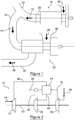
- the figure 1 schematically represents a turbine engine 10 equipped with a system 12 of energy recovery according to one embodiment of the invention.
- the energy recovery system 12 is adapted to recover at least a portion 14 of the exhaust gas from the turbine engine 10 in order to recover a portion of the thermal energy from the exhaust gases.
- These exhaust gases 16 are formed of gas 18 entering the turbine engine 10 via an inlet pipe, then mixed with fuel and burned in the turbine engine 10 in order to cause the rotation of a free turbine 20 at the turbine engine output. 10.
- the majority of the kinetic energy of the burned gases is recovered by the rotation of the free turbine, the residual kinetic energy allowing the evacuation of the exhaust gases at the outlet of this free turbine.
- the exhaust gases 16 are evacuated via an exhaust nozzle 22, allowing, in the context of the use of the turbine engine 10 in an aircraft, the evacuation of exhaust gases in the open air, outside the aircraft.
- the energy recovery system 12 makes it possible to extract a portion of these exhaust gases, represented by the arrow 14, for example by means of a sampling pipe 24 connected to the exhaust nozzle 22 of the turbine engine. 10. Part 14 of the exhaust gas is taken off by means of a turbine that allows the exhaust gases taken off to be exhausted, allowing the exhaust part 14 to be exhausted into the exhaust nozzle via the exhaust pipe. sampling line 24.
- the energy recovery system 12 comprises a plurality of sampling lines connected to a plurality of exhaust nozzles, for taking a portion of the exhaust gas from a plurality of turbine engines.
- the energy recovery system 12 also comprises an external air intake pipe 26, allowing the cooling of the gas taken off by the turbine by means of a heat exchanger present in the energy recovery system 12. Once the energy of the exhaust gas portion 14 has been recovered, the exhaust gases are discharged through a discharge line 32.
- This evacuation pipe 32 can also be used for evacuating the outside air after passing through the heat exchanger.
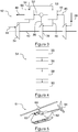
- the figure 2 schematically shows the system 12 of energy recovery according to a first embodiment.
- the turbine 34, a compressor 36 and a fan 38 are connected to a recovery shaft 40.
- the turbine 34 removes a part 14 of the exhaust gas from the exhaust nozzle 10, and allows the expansion of these exhaust gases and therefore a decrease in their temperature, thus forming relaxed gases, represented by the arrow 42.
- the pressure of the expanded gases 42 resulting from expansion by the turbine 34 is lower than the atmospheric pressure.
- the gases 42 expanded pass through a first heat exchanger 44 to allow their cooling, thereby forming cooled gases, represented by the arrow 46.
- the cooling of the gas 42 is relaxed at the first heat exchanger 44 through a cold source 45, brought here to the first heat exchanger 44 by the fan 38 rotated by the shaft 40 for recovery and allowing the supply of air 28 outside.
- the gases 46 cooled by the first heat exchanger 44 are transmitted to the compressor 36, connected to the recovery shaft 40.
- the compressor compresses the gases 46 cooled to obtain gases at a pressure substantially equal to atmospheric pressure, said outlet gases which are for example discharged through a discharge pipe 32 as previously shown with reference to FIG. figure 1 .
- the evacuation pipe also allows the evacuation of the cold source 45 after passing through the first heat exchanger 44.
- the evacuation of the cold source and the exit gases is represented by the arrow 48.
- the energy recovered by the energy recovery system 12 is usable in the form of mechanical energy transmitted by the recovery shaft 40.
- This recovered mechanical energy comes from the difference between the mechanical energy supplied to the shaft 40 of recovery by the rotation of the turbine 34 due to the passage of the portion 14 of the exhaust gas, and the mechanical energy from the recovery shaft 40 and consumed by the compressor 36 to compress the gases 46 cooled to a pressure substantially equal to atmospheric pressure.
- Cooling of the gases expanded by the first heat exchanger 44 makes it possible to reduce the temperature of the expanded gases and thus reduce the energy required for the compressor 36 to compress the gases cooled to atmospheric pressure.
- the amount of energy recovered is therefore dependent on the efficiency of the cooling by the first heat exchanger 44.
- the energy consumed by the fan 38 is also to be deduced from the recovered energy.
- the energy recovered at the recovery shaft 40 is then for example transmissible to other shafts of an aircraft, through a relay box, or converted into another form of energy.
- the expanded gases 42 have a temperature which remains high at the outlet of the turbine and at their passage through the first heat exchanger 44.
- the first heat exchanger 44 must be sized and in a material compatible with these high temperatures even if lower than the temperatures encountered in the exhaust nozzle 22 of the turbine engine 10.
- the energy recovery system 12 comprises a second heat exchanger 50 for previously cooling the gas 42 expanded before passing into said first heat exchanger 40, as shown with reference to the figure 3 .
- the elements unchanged compared to the embodiment of the figure 2 bear the same references.
- the pre-cooling in the second heat exchanger 50 is carried out by means of a second cold source 52, composed for example of the output gases at the outlet of the compressor and of the cold source 45 after passing through the first heat exchanger 44.
- the temperature of the gases 53 at the inlet of the first heat exchanger is lower.
- the first exchanger thus, thermal insulation can be made of a material with more suitable operating temperature constraints and allowing more efficient cooling and / or smaller and lighter sizing.
- a material resistant to high temperatures such as steel, has a thermal conductivity of the order of 15 W / m / ° C and a density of about 7800 kg / m 3 .
- the second heat exchanger 50 can thus be made of steel, for example.
- Aluminum has a lower high temperature resistance, but has a higher thermal conductivity, of the order of 150 W / m / ° C and a density of the order of 2700 kg / m 3 .
- the first heat exchanger 44 can thus be made, for example, of aluminum, allowing a more efficient cooling of the gases 53 passing therethrough, for a reduced weight.
- first heat exchanger 44 and the second heat exchanger 50 may be used for the manufacture of the first heat exchanger 44 and the second heat exchanger 50, depending on the temperature constraints, sizing and the desired performance, which may vary depending on the turboshaft engines of which at least a portion of the exhaust gases are taken, and according to the embodiments, to one or two exchangers.
- the heat exchangers and / or the materials used in these heat exchangers are already tested for application in an aircraft.
- the energy recovery system can use heat exchangers of the type used in air conditioning systems of a cabin of an aircraft, already proven for aeronautics.
- Prior cooling prior to passage into the first heat exchanger 44 is also performed, in this embodiment, through an inlet 51 of air, allowing the injection of outside air into the gas to the first heat exchanger 44.
- the mixing of the gases with the outside air thus makes it possible to lower the temperature. Outside air injection is further facilitated by the fact that the gases present in the energy recovery system 12 are at a pressure below atmospheric pressure.
- the energy recovery system 12 can comprise only the first heat exchanger 44, or the first heat exchanger 44 accompanied by the second heat exchanger 50, or accompanied by the air inlet 51, or else accompanied a combination of the second heat exchanger 50 thermal and air inlet 51.
- the figure 4 schematically represents a method 54 of energy recovery according to one embodiment of the invention.
- the method 54 of energy recovery comprises a step 55 of sampling at least a portion of the exhaust gases, called collected gases, coming from a turbine engine, as described with reference to FIG. figure 1 .
- the withdrawn gases are then expanded in a step 56 of expansion of the gases taken, for example by the turbine 34 in the energy recovery system 12 as described above.
- This step 56 of relaxation allows the formation of relaxed gas which, because of the drop in pressure, have a lower temperature than the gases taken.
- the expanded gases are then cooled in a cooling step 58 to form cooled gases. These cooled gases are then compressed during a compression step 60.
- the energy recovery method 54 thus implemented follows a thermodynamic cycle of Brayton cycle inverted vacuum type.
- the mechanical energy recovered by this cycle comes from the thermal energy included in the exhaust gases taken.
- the figure 5 schematically represents a helicopter 61 comprising a turbine engine 10 according to one embodiment of the invention.
- the turbine engine is equipped with a system 12 for energy recovery according to one embodiment of the invention.
- the energy-producing system 12 is connected to a rear shaft 62 of the helicopter 61.
- This rear shaft 62 allows the rotation of a tail rotor 64 of the helicopter 61, allowing the stabilization thereof, in particular by compensation of the torque exerted by the main rotor 66 driven by the turbine engine 10 via a main gearbox.
- the mechanical energy recovered by the energy recovery system 12 is thus transmitted by the recovery shaft 40 to the rear shaft 62 of the helicopter 61.
- the start of the energy recovery system 12 requires the prior rotation of the recovery shaft 40 connected to the turbine 34 and the compressor 36 by supplying an external energy, for example by the rear shaft 62. a helicopter.
- the system 12 of energy recovery is therefore energy receiver during startup. Once the operating point has been reached, the energy recovery system 12 reaches an equilibrium in which it becomes an engine by taking at least a portion of the exhaust gases that make it possible to recover mechanical energy.
- the cold source used at the exchanger or exchangers can be in various forms, for example an electric fan air inlet or a horn, etc.
- the reuse of the mechanical energy generated by the system can be performed in a different form, for example by the level of the main gearbox (BTP) of the helicopter, or by transformation into pneumatic energy, electrical, etc.
- the energy recovery system may include more than two exchangers.
Landscapes
- Engineering & Computer Science (AREA)
- Chemical & Material Sciences (AREA)
- Combustion & Propulsion (AREA)
- Mechanical Engineering (AREA)
- General Engineering & Computer Science (AREA)
- Aviation & Aerospace Engineering (AREA)
- Engine Equipment That Uses Special Cycles (AREA)
Claims (6)
- Turbomotor (10), umfassend ein System zur Rückgewinnung von Energie aus Abgas (16) des Turbomotors (10), umfassend:- eine Turbine (34), die drehbeweglich um eine Rückgewinnungswelle (40) befestigt ist, angepasst, um mindestens einen Teil (14) der Abgase, als entnommene Gase bezeichnet, zu entnehmen, und um die entnommenen Gase zu entspannten Gasen (42) auf einen Druck unter dem Atmosphärendruck zu entspannen,- einen ersten Wärmetauscher (44), der angepasst ist, um die entspannten Gase (42) mithilfe einer kalten Quelle (45) zu abgekühlten Gasen (46) abzukühlen,- einen Verdichter (36), der drehbeweglich um die Rückgewinnungswelle (40) befestigt ist, angepasst, um die abgekühlten Gase (46) auf den Atmosphärendruck zu verdichten,- einen Lüfter (38), der konfiguriert ist, um die kalte Quelle (45) zum ersten Wärmetauscher (44) zu bringen, wobei der Lüfter (38) durch die Rückgewinnungswelle (40) in Drehbewegung versetzt wird,wobei der Turbomotor weiter eine freie Turbine (20) umfasst, die eine freie Turbinenwelle in Drehbewegung versetzt, und dadurch gekennzeichnet ist, dass die Rückgewinnungswelle (40) mit der freien Turbinenwelle verbunden ist.
- Turbomotor (10) nach Anspruch 1, wobei das System zur Rückgewinnung von Energie einen zweiten Wärmetauscher (50) umfasst, angepasst, um vor dem Durchgang in den ersten Wärmetauscher (44) eine Vorabkühlung der entspannten Gase (42) durchzuführen.
- Turbomotor (10) nach einem der Ansprüche 1 oder 2, wobei das System zur Rückgewinnung von Energie einen Lufteingang (51) umfasst, angepasst, um vor dem Durchgang in den ersten Wärmetauscher (44) eine Vorabkühlung der entspannten Gase (42) durchzuführen.
- Turbomotor (10) nach einem der Ansprüche 1 bis 3, wobei das System zur Rückgewinnung von Energie eine Vielzahl von Leitungen (24) umfasst, die die Turbine (34) mit einer Vielzahl von Abgasdüsen (22) verbindet, um Abgase (16), die aus einer Vielzahl von Turbomotoren (10) stammen, zu entnehmen.
- Hubschrauber, umfassend einen Turbomotor (10) nach einem der Ansprüche 1 bis 4.
- Hubschrauber nach Anspruch 5, weiter einen Heckrotor (64) umfassend, der durch eine hintere Welle (62) angetrieben wird, dadurch gekennzeichnet, dass die Rückgewinnungswelle (40) mit der hinteren Welle (62) verbunden ist.
Priority Applications (1)
| Application Number | Priority Date | Filing Date | Title |
|---|---|---|---|
| PL16713955T PL3259462T3 (pl) | 2015-02-17 | 2016-02-15 | Układ odzyskiwania energii gazów spalinowych |
Applications Claiming Priority (2)
| Application Number | Priority Date | Filing Date | Title |
|---|---|---|---|
| FR1551319A FR3032747B1 (fr) | 2015-02-17 | 2015-02-17 | Systeme de recuperation d'energie de gaz d'echappement |
| PCT/FR2016/050341 WO2016132057A1 (fr) | 2015-02-17 | 2016-02-15 | Systeme de recuperation d'energie de gaz d'echappement |
Publications (2)
| Publication Number | Publication Date |
|---|---|
| EP3259462A1 EP3259462A1 (de) | 2017-12-27 |
| EP3259462B1 true EP3259462B1 (de) | 2019-11-06 |
Family
ID=52829167
Family Applications (1)
| Application Number | Title | Priority Date | Filing Date |
|---|---|---|---|
| EP16713955.9A Active EP3259462B1 (de) | 2015-02-17 | 2016-02-15 | System zur rückgewinnung der energie aus einem abgas |
Country Status (10)
| Country | Link |
|---|---|
| US (1) | US10683804B2 (de) |
| EP (1) | EP3259462B1 (de) |
| JP (1) | JP6637510B2 (de) |
| KR (1) | KR20170117385A (de) |
| CN (1) | CN107110023B (de) |
| CA (1) | CA2973056A1 (de) |
| FR (1) | FR3032747B1 (de) |
| PL (1) | PL3259462T3 (de) |
| RU (1) | RU2703886C2 (de) |
| WO (1) | WO2016132057A1 (de) |
Families Citing this family (7)
| Publication number | Priority date | Publication date | Assignee | Title |
|---|---|---|---|---|
| FR3082225B1 (fr) * | 2018-06-07 | 2020-06-05 | Safran Helicopter Engines | Systeme propulsif asymetrique a recuperation de chaleur |
| GB202203460D0 (en) * | 2019-09-13 | 2022-04-27 | Lavrentiev Vladimir | Gas turbine engine |
| US11428162B2 (en) | 2020-01-17 | 2022-08-30 | Raytheon Technologies Corporation | Supercritical CO2 cycle for gas turbine engines using powered cooling flow |
| US11480103B2 (en) | 2020-01-17 | 2022-10-25 | Raytheon Technologies Corporation | Supercritical CO2 cycle for gas turbine engines using partial core exhaust flow |
| US11946415B2 (en) | 2021-09-09 | 2024-04-02 | General Electric Company | Waste heat recovery system |
| US11939913B2 (en) | 2022-02-11 | 2024-03-26 | Rtx Corporation | Turbine engine with inverse Brayton cycle |
| US12037943B2 (en) | 2022-10-07 | 2024-07-16 | General Electric Company | Waste heat recovery system |
Family Cites Families (13)
| Publication number | Priority date | Publication date | Assignee | Title |
|---|---|---|---|---|
| US2623357A (en) * | 1945-09-06 | 1952-12-30 | Birmann Rudolph | Gas turbine power plant having means to cool and means to compress combustion products passing through the turbine |
| US2524066A (en) * | 1947-01-03 | 1950-10-03 | Soren K Andersen | Aircraft heat exchanger |
| FR1166419A (fr) * | 1955-07-08 | 1958-11-12 | Procédé et moyens de mise en oeuvre pour tirer de l'énergie mécanique de la chaleur sensible d'une masse gazeuse chaude, sensiblement à la pression atmosphérique ambiante, et application aux turbines à gaz | |
| IT1071240B (it) * | 1976-07-09 | 1985-04-02 | Fiat Spa | Motore a combustione interna munito di dispositivo per diminuire la pressione dei gas di scarico |
| GB1557817A (en) * | 1977-08-25 | 1979-12-12 | Penny Turbines Ltd Noel | Gas turbine ducted fan engines having expansion to sub atmospheric pressure |
| US4700542A (en) * | 1984-09-21 | 1987-10-20 | Wang Lin Shu | Internal combustion engines and methods of operation |
| RU2110692C1 (ru) * | 1996-05-23 | 1998-05-10 | Борис Хаимович Перельштейн | Газотурбинная установка |
| RU2189546C2 (ru) * | 2000-07-05 | 2002-09-20 | Открытое акционерное общество "Рыбинские моторы" | Энергетическая установка |
| JP2003193865A (ja) * | 2001-12-27 | 2003-07-09 | Kansai Tlo Kk | ガスタービン発電システム及びガスタービン動力システムおよびその起動方法 |
| WO2010058356A2 (en) * | 2008-11-20 | 2010-05-27 | Etv Motors Ltd. | Valves for gas-turbines and multipressure gas-turbines, and gas-turbines therewith |
| CN101509426B (zh) * | 2009-03-31 | 2011-07-27 | 严政 | 一种涡轮轴发动机 |
| CN101875399B (zh) * | 2009-10-30 | 2013-06-19 | 北京航空航天大学 | 一种采用并列式共轴双旋翼的倾转旋翼飞机 |
| FR3011277B1 (fr) * | 2013-09-30 | 2018-04-06 | Turbomeca | Turbomachine adaptee a fonctionner en mode vireur |
-
2015
- 2015-02-17 FR FR1551319A patent/FR3032747B1/fr active Active
-
2016
- 2016-02-15 WO PCT/FR2016/050341 patent/WO2016132057A1/fr not_active Ceased
- 2016-02-15 CA CA2973056A patent/CA2973056A1/fr not_active Abandoned
- 2016-02-15 JP JP2017536265A patent/JP6637510B2/ja not_active Expired - Fee Related
- 2016-02-15 PL PL16713955T patent/PL3259462T3/pl unknown
- 2016-02-15 CN CN201680005308.2A patent/CN107110023B/zh active Active
- 2016-02-15 KR KR1020177019007A patent/KR20170117385A/ko not_active Withdrawn
- 2016-02-15 EP EP16713955.9A patent/EP3259462B1/de active Active
- 2016-02-15 RU RU2017124002A patent/RU2703886C2/ru not_active IP Right Cessation
- 2016-02-15 US US15/542,057 patent/US10683804B2/en active Active
Non-Patent Citations (1)
| Title |
|---|
| None * |
Also Published As
| Publication number | Publication date |
|---|---|
| FR3032747B1 (fr) | 2019-03-15 |
| WO2016132057A1 (fr) | 2016-08-25 |
| RU2703886C2 (ru) | 2019-10-22 |
| JP2018510281A (ja) | 2018-04-12 |
| RU2017124002A (ru) | 2019-03-18 |
| PL3259462T3 (pl) | 2020-05-18 |
| CA2973056A1 (fr) | 2016-08-25 |
| KR20170117385A (ko) | 2017-10-23 |
| FR3032747A1 (fr) | 2016-08-19 |
| CN107110023A (zh) | 2017-08-29 |
| US20180274441A1 (en) | 2018-09-27 |
| JP6637510B2 (ja) | 2020-01-29 |
| US10683804B2 (en) | 2020-06-16 |
| EP3259462A1 (de) | 2017-12-27 |
| RU2017124002A3 (de) | 2019-08-12 |
| CN107110023B (zh) | 2019-12-06 |
Similar Documents
| Publication | Publication Date | Title |
|---|---|---|
| EP3259462B1 (de) | System zur rückgewinnung der energie aus einem abgas | |
| FR3027624A1 (fr) | Circuit de degivrage d'une levre d'entree d'air d'un ensemble propulsif d'aeronef | |
| EP3070317B1 (de) | Kühlung für turbomaschine durch verdampfung | |
| CA2888717C (fr) | Procede et systeme de conditionnement d'air pour aeronef | |
| FR2859500A1 (fr) | Procede d'assemblage d'un moteur a turbines prevenant l'accumulation de glace dans le moteur et systeme de protection contre le gel | |
| EP3418194B1 (de) | Klimaanlage und entsprechendes verfahren für die kabine eines luftfahrzeugs, und luftfahrzeug, das mit einer solchen anlage ausgestattet ist | |
| FR3048999A1 (fr) | Turboreacteur a faible jeu entre la soufflante et le carter de soufflante | |
| FR2980836A1 (fr) | Echangeur de chaleur formant prerefroidisseur d'avion | |
| FR3065490A1 (fr) | Ensemble propulsif pour aeronef comportant des echangeurs de chaleur air-liquide | |
| WO2017085406A1 (fr) | Ensemble propulsif comprenant un moteur principal et un moteur auxiliaire | |
| FR2481747A1 (fr) | Moteur a turbine a gaz comportant un dispositif perfectionne de refroidissement par air | |
| WO2014057227A1 (fr) | Moteur thermique pour l'entrainement d'un arbre moteur | |
| WO2017109330A1 (fr) | Turboréacteur avec un moyen de reprise de poussée sur le carter inter-compresseurs | |
| FR3040736A1 (fr) | Entretoise de cadre d'echappement a ailettes de refroidissement | |
| WO2023084176A1 (fr) | Procédé de fabrication d'un dispositif de protection métallique du bord d'attaque d'une aube intégrant un système de dégivrage et dispositif de protection obtenu par ce procédé | |
| FR3084909A1 (fr) | Moteur à turbine à gaz efficace | |
| FR2931193A1 (fr) | Systemes et procedes pour refroidir des organes chauffes d'une turbine. | |
| FR3084908A1 (fr) | Moteur d'aéronef à rendement propulsif et thermique élevé | |
| FR3128971A1 (fr) | Turbomachine d'aéronef et procédé associé | |
| FR3107307A1 (fr) | Système de récupération de chaleur pour système propulsif | |
| FR3107308A1 (fr) | Système de soufflage pour système propulsif d’aéronef | |
| FR2966522A1 (fr) | Turbomachine a double soufflante et triple flux | |
| FR3057301A1 (fr) | Procede de chauffage et de sechage d'une entree d'air d'un moteur a combustion interne | |
| FR3062972A1 (fr) | Dispositif de generation d'energie electrique auxiliaire et turbomachine comportant un tel dispositif | |
| CH97143A (fr) | Procédé pour la production de force motrice au moyen d'une turbine à combustion. |
Legal Events
| Date | Code | Title | Description |
|---|---|---|---|
| STAA | Information on the status of an ep patent application or granted ep patent |
Free format text: STATUS: THE INTERNATIONAL PUBLICATION HAS BEEN MADE |
|
| PUAI | Public reference made under article 153(3) epc to a published international application that has entered the european phase |
Free format text: ORIGINAL CODE: 0009012 |
|
| STAA | Information on the status of an ep patent application or granted ep patent |
Free format text: STATUS: REQUEST FOR EXAMINATION WAS MADE |
|
| 17P | Request for examination filed |
Effective date: 20170803 |
|
| AK | Designated contracting states |
Kind code of ref document: A1 Designated state(s): AL AT BE BG CH CY CZ DE DK EE ES FI FR GB GR HR HU IE IS IT LI LT LU LV MC MK MT NL NO PL PT RO RS SE SI SK SM TR |
|
| AX | Request for extension of the european patent |
Extension state: BA ME |
|
| DAV | Request for validation of the european patent (deleted) | ||
| DAX | Request for extension of the european patent (deleted) | ||
| RAP1 | Party data changed (applicant data changed or rights of an application transferred) |
Owner name: SAFRAN HELICOPTER ENGINES |
|
| STAA | Information on the status of an ep patent application or granted ep patent |
Free format text: STATUS: EXAMINATION IS IN PROGRESS |
|
| 17Q | First examination report despatched |
Effective date: 20181019 |
|
| GRAJ | Information related to disapproval of communication of intention to grant by the applicant or resumption of examination proceedings by the epo deleted |
Free format text: ORIGINAL CODE: EPIDOSDIGR1 |
|
| GRAP | Despatch of communication of intention to grant a patent |
Free format text: ORIGINAL CODE: EPIDOSNIGR1 |
|
| GRAP | Despatch of communication of intention to grant a patent |
Free format text: ORIGINAL CODE: EPIDOSNIGR1 |
|
| STAA | Information on the status of an ep patent application or granted ep patent |
Free format text: STATUS: GRANT OF PATENT IS INTENDED |
|
| INTG | Intention to grant announced |
Effective date: 20190722 |
|
| GRAS | Grant fee paid |
Free format text: ORIGINAL CODE: EPIDOSNIGR3 |
|
| GRAA | (expected) grant |
Free format text: ORIGINAL CODE: 0009210 |
|
| STAA | Information on the status of an ep patent application or granted ep patent |
Free format text: STATUS: THE PATENT HAS BEEN GRANTED |
|
| AK | Designated contracting states |
Kind code of ref document: B1 Designated state(s): AL AT BE BG CH CY CZ DE DK EE ES FI FR GB GR HR HU IE IS IT LI LT LU LV MC MK MT NL NO PL PT RO RS SE SI SK SM TR |
|
| REG | Reference to a national code |
Ref country code: GB Ref legal event code: FG4D Free format text: NOT ENGLISH |
|
| REG | Reference to a national code |
Ref country code: CH Ref legal event code: EP Ref country code: AT Ref legal event code: REF Ref document number: 1199004 Country of ref document: AT Kind code of ref document: T Effective date: 20191115 |
|
| REG | Reference to a national code |
Ref country code: IE Ref legal event code: FG4D Free format text: LANGUAGE OF EP DOCUMENT: FRENCH |
|
| REG | Reference to a national code |
Ref country code: DE Ref legal event code: R096 Ref document number: 602016023738 Country of ref document: DE |
|
| REG | Reference to a national code |
Ref country code: NL Ref legal event code: MP Effective date: 20191106 |
|
| REG | Reference to a national code |
Ref country code: LT Ref legal event code: MG4D |
|
| PG25 | Lapsed in a contracting state [announced via postgrant information from national office to epo] |
Ref country code: NL Free format text: LAPSE BECAUSE OF FAILURE TO SUBMIT A TRANSLATION OF THE DESCRIPTION OR TO PAY THE FEE WITHIN THE PRESCRIBED TIME-LIMIT Effective date: 20191106 Ref country code: SE Free format text: LAPSE BECAUSE OF FAILURE TO SUBMIT A TRANSLATION OF THE DESCRIPTION OR TO PAY THE FEE WITHIN THE PRESCRIBED TIME-LIMIT Effective date: 20191106 Ref country code: LV Free format text: LAPSE BECAUSE OF FAILURE TO SUBMIT A TRANSLATION OF THE DESCRIPTION OR TO PAY THE FEE WITHIN THE PRESCRIBED TIME-LIMIT Effective date: 20191106 Ref country code: GR Free format text: LAPSE BECAUSE OF FAILURE TO SUBMIT A TRANSLATION OF THE DESCRIPTION OR TO PAY THE FEE WITHIN THE PRESCRIBED TIME-LIMIT Effective date: 20200207 Ref country code: NO Free format text: LAPSE BECAUSE OF FAILURE TO SUBMIT A TRANSLATION OF THE DESCRIPTION OR TO PAY THE FEE WITHIN THE PRESCRIBED TIME-LIMIT Effective date: 20200206 Ref country code: BG Free format text: LAPSE BECAUSE OF FAILURE TO SUBMIT A TRANSLATION OF THE DESCRIPTION OR TO PAY THE FEE WITHIN THE PRESCRIBED TIME-LIMIT Effective date: 20200206 Ref country code: FI Free format text: LAPSE BECAUSE OF FAILURE TO SUBMIT A TRANSLATION OF THE DESCRIPTION OR TO PAY THE FEE WITHIN THE PRESCRIBED TIME-LIMIT Effective date: 20191106 Ref country code: PT Free format text: LAPSE BECAUSE OF FAILURE TO SUBMIT A TRANSLATION OF THE DESCRIPTION OR TO PAY THE FEE WITHIN THE PRESCRIBED TIME-LIMIT Effective date: 20200306 Ref country code: LT Free format text: LAPSE BECAUSE OF FAILURE TO SUBMIT A TRANSLATION OF THE DESCRIPTION OR TO PAY THE FEE WITHIN THE PRESCRIBED TIME-LIMIT Effective date: 20191106 |
|
| PG25 | Lapsed in a contracting state [announced via postgrant information from national office to epo] |
Ref country code: HR Free format text: LAPSE BECAUSE OF FAILURE TO SUBMIT A TRANSLATION OF THE DESCRIPTION OR TO PAY THE FEE WITHIN THE PRESCRIBED TIME-LIMIT Effective date: 20191106 Ref country code: IS Free format text: LAPSE BECAUSE OF FAILURE TO SUBMIT A TRANSLATION OF THE DESCRIPTION OR TO PAY THE FEE WITHIN THE PRESCRIBED TIME-LIMIT Effective date: 20200306 Ref country code: RS Free format text: LAPSE BECAUSE OF FAILURE TO SUBMIT A TRANSLATION OF THE DESCRIPTION OR TO PAY THE FEE WITHIN THE PRESCRIBED TIME-LIMIT Effective date: 20191106 |
|
| PG25 | Lapsed in a contracting state [announced via postgrant information from national office to epo] |
Ref country code: AL Free format text: LAPSE BECAUSE OF FAILURE TO SUBMIT A TRANSLATION OF THE DESCRIPTION OR TO PAY THE FEE WITHIN THE PRESCRIBED TIME-LIMIT Effective date: 20191106 |
|
| PG25 | Lapsed in a contracting state [announced via postgrant information from national office to epo] |
Ref country code: ES Free format text: LAPSE BECAUSE OF FAILURE TO SUBMIT A TRANSLATION OF THE DESCRIPTION OR TO PAY THE FEE WITHIN THE PRESCRIBED TIME-LIMIT Effective date: 20191106 Ref country code: RO Free format text: LAPSE BECAUSE OF FAILURE TO SUBMIT A TRANSLATION OF THE DESCRIPTION OR TO PAY THE FEE WITHIN THE PRESCRIBED TIME-LIMIT Effective date: 20191106 Ref country code: EE Free format text: LAPSE BECAUSE OF FAILURE TO SUBMIT A TRANSLATION OF THE DESCRIPTION OR TO PAY THE FEE WITHIN THE PRESCRIBED TIME-LIMIT Effective date: 20191106 Ref country code: DK Free format text: LAPSE BECAUSE OF FAILURE TO SUBMIT A TRANSLATION OF THE DESCRIPTION OR TO PAY THE FEE WITHIN THE PRESCRIBED TIME-LIMIT Effective date: 20191106 |
|
| REG | Reference to a national code |
Ref country code: DE Ref legal event code: R097 Ref document number: 602016023738 Country of ref document: DE |
|
| REG | Reference to a national code |
Ref country code: AT Ref legal event code: MK05 Ref document number: 1199004 Country of ref document: AT Kind code of ref document: T Effective date: 20191106 |
|
| PG25 | Lapsed in a contracting state [announced via postgrant information from national office to epo] |
Ref country code: SM Free format text: LAPSE BECAUSE OF FAILURE TO SUBMIT A TRANSLATION OF THE DESCRIPTION OR TO PAY THE FEE WITHIN THE PRESCRIBED TIME-LIMIT Effective date: 20191106 Ref country code: SK Free format text: LAPSE BECAUSE OF FAILURE TO SUBMIT A TRANSLATION OF THE DESCRIPTION OR TO PAY THE FEE WITHIN THE PRESCRIBED TIME-LIMIT Effective date: 20191106 |
|
| PLBE | No opposition filed within time limit |
Free format text: ORIGINAL CODE: 0009261 |
|
| STAA | Information on the status of an ep patent application or granted ep patent |
Free format text: STATUS: NO OPPOSITION FILED WITHIN TIME LIMIT |
|
| REG | Reference to a national code |
Ref country code: CH Ref legal event code: PL |
|
| 26N | No opposition filed |
Effective date: 20200807 |
|
| REG | Reference to a national code |
Ref country code: BE Ref legal event code: MM Effective date: 20200229 |
|
| PG25 | Lapsed in a contracting state [announced via postgrant information from national office to epo] |
Ref country code: LU Free format text: LAPSE BECAUSE OF NON-PAYMENT OF DUE FEES Effective date: 20200215 Ref country code: MC Free format text: LAPSE BECAUSE OF FAILURE TO SUBMIT A TRANSLATION OF THE DESCRIPTION OR TO PAY THE FEE WITHIN THE PRESCRIBED TIME-LIMIT Effective date: 20191106 |
|
| PG25 | Lapsed in a contracting state [announced via postgrant information from national office to epo] |
Ref country code: LI Free format text: LAPSE BECAUSE OF NON-PAYMENT OF DUE FEES Effective date: 20200229 Ref country code: AT Free format text: LAPSE BECAUSE OF FAILURE TO SUBMIT A TRANSLATION OF THE DESCRIPTION OR TO PAY THE FEE WITHIN THE PRESCRIBED TIME-LIMIT Effective date: 20191106 Ref country code: SI Free format text: LAPSE BECAUSE OF FAILURE TO SUBMIT A TRANSLATION OF THE DESCRIPTION OR TO PAY THE FEE WITHIN THE PRESCRIBED TIME-LIMIT Effective date: 20191106 Ref country code: CH Free format text: LAPSE BECAUSE OF NON-PAYMENT OF DUE FEES Effective date: 20200229 |
|
| PG25 | Lapsed in a contracting state [announced via postgrant information from national office to epo] |
Ref country code: IE Free format text: LAPSE BECAUSE OF NON-PAYMENT OF DUE FEES Effective date: 20200215 |
|
| PG25 | Lapsed in a contracting state [announced via postgrant information from national office to epo] |
Ref country code: BE Free format text: LAPSE BECAUSE OF NON-PAYMENT OF DUE FEES Effective date: 20200229 |
|
| PG25 | Lapsed in a contracting state [announced via postgrant information from national office to epo] |
Ref country code: TR Free format text: LAPSE BECAUSE OF FAILURE TO SUBMIT A TRANSLATION OF THE DESCRIPTION OR TO PAY THE FEE WITHIN THE PRESCRIBED TIME-LIMIT Effective date: 20191106 Ref country code: MT Free format text: LAPSE BECAUSE OF FAILURE TO SUBMIT A TRANSLATION OF THE DESCRIPTION OR TO PAY THE FEE WITHIN THE PRESCRIBED TIME-LIMIT Effective date: 20191106 Ref country code: CY Free format text: LAPSE BECAUSE OF FAILURE TO SUBMIT A TRANSLATION OF THE DESCRIPTION OR TO PAY THE FEE WITHIN THE PRESCRIBED TIME-LIMIT Effective date: 20191106 |
|
| PG25 | Lapsed in a contracting state [announced via postgrant information from national office to epo] |
Ref country code: MK Free format text: LAPSE BECAUSE OF FAILURE TO SUBMIT A TRANSLATION OF THE DESCRIPTION OR TO PAY THE FEE WITHIN THE PRESCRIBED TIME-LIMIT Effective date: 20191106 |
|
| PGFP | Annual fee paid to national office [announced via postgrant information from national office to epo] |
Ref country code: DE Payment date: 20250122 Year of fee payment: 10 |
|
| PGFP | Annual fee paid to national office [announced via postgrant information from national office to epo] |
Ref country code: FR Payment date: 20250122 Year of fee payment: 10 Ref country code: PL Payment date: 20250122 Year of fee payment: 10 Ref country code: CZ Payment date: 20250128 Year of fee payment: 10 |
|
| PGFP | Annual fee paid to national office [announced via postgrant information from national office to epo] |
Ref country code: IT Payment date: 20250121 Year of fee payment: 10 Ref country code: GB Payment date: 20250123 Year of fee payment: 10 |