EP3259083B1 - Verfahren zum hochtemperaturschmieden eines vorgeformten metallteils und zum schmieden geeignete formgebungsausrüstung - Google Patents
Verfahren zum hochtemperaturschmieden eines vorgeformten metallteils und zum schmieden geeignete formgebungsausrüstung Download PDFInfo
- Publication number
- EP3259083B1 EP3259083B1 EP16707886.4A EP16707886A EP3259083B1 EP 3259083 B1 EP3259083 B1 EP 3259083B1 EP 16707886 A EP16707886 A EP 16707886A EP 3259083 B1 EP3259083 B1 EP 3259083B1
- Authority
- EP
- European Patent Office
- Prior art keywords
- metal part
- preformed metal
- die
- forging
- tooling
- Prior art date
- Legal status (The legal status is an assumption and is not a legal conclusion. Google has not performed a legal analysis and makes no representation as to the accuracy of the status listed.)
- Active
Links
Images


Classifications
-
- B—PERFORMING OPERATIONS; TRANSPORTING
- B21—MECHANICAL METAL-WORKING WITHOUT ESSENTIALLY REMOVING MATERIAL; PUNCHING METAL
- B21D—WORKING OR PROCESSING OF SHEET METAL OR METAL TUBES, RODS OR PROFILES WITHOUT ESSENTIALLY REMOVING MATERIAL; PUNCHING METAL
- B21D53/00—Making other particular articles
- B21D53/78—Making other particular articles propeller blades; turbine blades
-
- B—PERFORMING OPERATIONS; TRANSPORTING
- B21—MECHANICAL METAL-WORKING WITHOUT ESSENTIALLY REMOVING MATERIAL; PUNCHING METAL
- B21K—MAKING FORGED OR PRESSED METAL PRODUCTS, e.g. HORSE-SHOES, RIVETS, BOLTS OR WHEELS
- B21K3/00—Making engine or like machine parts not covered by sub-groups of B21K1/00; Making propellers or the like
- B21K3/04—Making engine or like machine parts not covered by sub-groups of B21K1/00; Making propellers or the like blades, e.g. for turbines; Upsetting of blade roots
-
- B—PERFORMING OPERATIONS; TRANSPORTING
- B21—MECHANICAL METAL-WORKING WITHOUT ESSENTIALLY REMOVING MATERIAL; PUNCHING METAL
- B21K—MAKING FORGED OR PRESSED METAL PRODUCTS, e.g. HORSE-SHOES, RIVETS, BOLTS OR WHEELS
- B21K25/00—Uniting components to form integral members, e.g. turbine wheels and shafts, caulks with inserts, with or without shaping of the components
-
- F—MECHANICAL ENGINEERING; LIGHTING; HEATING; WEAPONS; BLASTING
- F01—MACHINES OR ENGINES IN GENERAL; ENGINE PLANTS IN GENERAL; STEAM ENGINES
- F01D—NON-POSITIVE DISPLACEMENT MACHINES OR ENGINES, e.g. STEAM TURBINES
- F01D5/00—Blades; Blade-carrying members; Heating, heat-insulating, cooling or antivibration means on the blades or the members
- F01D5/12—Blades
- F01D5/14—Form or construction
- F01D5/147—Construction, i.e. structural features, e.g. of weight-saving hollow blades
-
- F—MECHANICAL ENGINEERING; LIGHTING; HEATING; WEAPONS; BLASTING
- F01—MACHINES OR ENGINES IN GENERAL; ENGINE PLANTS IN GENERAL; STEAM ENGINES
- F01D—NON-POSITIVE DISPLACEMENT MACHINES OR ENGINES, e.g. STEAM TURBINES
- F01D5/00—Blades; Blade-carrying members; Heating, heat-insulating, cooling or antivibration means on the blades or the members
- F01D5/12—Blades
- F01D5/28—Selecting particular materials; Particular measures relating thereto; Measures against erosion or corrosion
- F01D5/282—Selecting composite materials, e.g. blades with reinforcing filaments
-
- F—MECHANICAL ENGINEERING; LIGHTING; HEATING; WEAPONS; BLASTING
- F01—MACHINES OR ENGINES IN GENERAL; ENGINE PLANTS IN GENERAL; STEAM ENGINES
- F01D—NON-POSITIVE DISPLACEMENT MACHINES OR ENGINES, e.g. STEAM TURBINES
- F01D5/00—Blades; Blade-carrying members; Heating, heat-insulating, cooling or antivibration means on the blades or the members
- F01D5/12—Blades
- F01D5/28—Selecting particular materials; Particular measures relating thereto; Measures against erosion or corrosion
- F01D5/286—Particular treatment of blades, e.g. to increase durability or resistance against corrosion or erosion
-
- F—MECHANICAL ENGINEERING; LIGHTING; HEATING; WEAPONS; BLASTING
- F04—POSITIVE - DISPLACEMENT MACHINES FOR LIQUIDS; PUMPS FOR LIQUIDS OR ELASTIC FLUIDS
- F04D—NON-POSITIVE-DISPLACEMENT PUMPS
- F04D29/00—Details, component parts, or accessories
- F04D29/02—Selection of particular materials
- F04D29/023—Selection of particular materials especially adapted for elastic fluid pumps
-
- F—MECHANICAL ENGINEERING; LIGHTING; HEATING; WEAPONS; BLASTING
- F04—POSITIVE - DISPLACEMENT MACHINES FOR LIQUIDS; PUMPS FOR LIQUIDS OR ELASTIC FLUIDS
- F04D—NON-POSITIVE-DISPLACEMENT PUMPS
- F04D29/00—Details, component parts, or accessories
- F04D29/26—Rotors specially for elastic fluids
- F04D29/32—Rotors specially for elastic fluids for axial flow pumps
- F04D29/321—Rotors specially for elastic fluids for axial flow pumps for axial flow compressors
- F04D29/324—Blades
-
- B—PERFORMING OPERATIONS; TRANSPORTING
- B21—MECHANICAL METAL-WORKING WITHOUT ESSENTIALLY REMOVING MATERIAL; PUNCHING METAL
- B21J—FORGING; HAMMERING; PRESSING METAL; RIVETING; FORGE FURNACES
- B21J13/00—Details of machines for forging, pressing, or hammering
- B21J13/02—Dies or mountings therefor
-
- F—MECHANICAL ENGINEERING; LIGHTING; HEATING; WEAPONS; BLASTING
- F05—INDEXING SCHEMES RELATING TO ENGINES OR PUMPS IN VARIOUS SUBCLASSES OF CLASSES F01-F04
- F05D—INDEXING SCHEME FOR ASPECTS RELATING TO NON-POSITIVE-DISPLACEMENT MACHINES OR ENGINES, GAS-TURBINES OR JET-PROPULSION PLANTS
- F05D2220/00—Application
- F05D2220/30—Application in turbines
- F05D2220/36—Application in turbines specially adapted for the fan of turbofan engines
-
- F—MECHANICAL ENGINEERING; LIGHTING; HEATING; WEAPONS; BLASTING
- F05—INDEXING SCHEMES RELATING TO ENGINES OR PUMPS IN VARIOUS SUBCLASSES OF CLASSES F01-F04
- F05D—INDEXING SCHEME FOR ASPECTS RELATING TO NON-POSITIVE-DISPLACEMENT MACHINES OR ENGINES, GAS-TURBINES OR JET-PROPULSION PLANTS
- F05D2230/00—Manufacture
- F05D2230/20—Manufacture essentially without removing material
- F05D2230/25—Manufacture essentially without removing material by forging
-
- F—MECHANICAL ENGINEERING; LIGHTING; HEATING; WEAPONS; BLASTING
- F05—INDEXING SCHEMES RELATING TO ENGINES OR PUMPS IN VARIOUS SUBCLASSES OF CLASSES F01-F04
- F05D—INDEXING SCHEME FOR ASPECTS RELATING TO NON-POSITIVE-DISPLACEMENT MACHINES OR ENGINES, GAS-TURBINES OR JET-PROPULSION PLANTS
- F05D2240/00—Components
- F05D2240/20—Rotors
- F05D2240/30—Characteristics of rotor blades, i.e. of any element transforming dynamic fluid energy to or from rotational energy and being attached to a rotor
- F05D2240/303—Characteristics of rotor blades, i.e. of any element transforming dynamic fluid energy to or from rotational energy and being attached to a rotor related to the leading edge of a rotor blade
-
- Y—GENERAL TAGGING OF NEW TECHNOLOGICAL DEVELOPMENTS; GENERAL TAGGING OF CROSS-SECTIONAL TECHNOLOGIES SPANNING OVER SEVERAL SECTIONS OF THE IPC; TECHNICAL SUBJECTS COVERED BY FORMER USPC CROSS-REFERENCE ART COLLECTIONS [XRACs] AND DIGESTS
- Y02—TECHNOLOGIES OR APPLICATIONS FOR MITIGATION OR ADAPTATION AGAINST CLIMATE CHANGE
- Y02T—CLIMATE CHANGE MITIGATION TECHNOLOGIES RELATED TO TRANSPORTATION
- Y02T50/00—Aeronautics or air transport
- Y02T50/60—Efficient propulsion technologies, e.g. for aircraft
Definitions
- the field of the invention is that of turbomachines, in particular that of the fan blades, made of composite material, of turbomachines whose leading edge comprises a metallic structural reinforcement, and the present invention more particularly relates to a method of forging at high temperature.
- metal parts such as, for example, a metal structural reinforcement of a turbomachine composite blade leading edge.
- the invention is equally applicable to the production of all pieces of complex geometrical shape and to the production of metal reinforcements intended to reinforce a leading edge or a blade trailing edge of any type of turbomachine, whether terrestrial or aeronautics, and in particular a helicopter turbine engine or an airplane turbojet engine.
- the metallic structural reinforcement protects the leading edge of the composite blade by avoiding risks of delamination, fiber breakage or damage by fiber / matrix decohesion.
- it is made either entirely by milling from a titanium block, which requires many rework operations and complex tools involving significant production costs or from a preform obtained from a simple metal bar and a succession of forging steps, as described in particular in the patent application FR2961866 filed in the name of the plaintiff.
- said metal part comprises a trunnion at each of its two ends and said locking of said metal part in said tooling is obtained by embedding one of said two trunnions and pivoting the other of said two trunnions.
- the displacement of said movable central insert is guided by the displacement of said first matrix and said single extraction direction is perpendicular to said common direction of displacement.
- said at least two cutting zones comprise at least two truncated portions made at both ends of said movable central insert.
- said first matrix is a fixed lower matrix and said second matrix is a mobile upper matrix.
- the invention also relates to a form of tooling suitable for high temperature forging of a preformed metal part obtained by the forging process mentioned above.
- the figure 1 is a partial sectional view of a composite blade comprising a metallic leading edge structural reinforcement obtained by means of the forging method according to the invention.
- the blade 10 illustrated is for example a mobile blade of a turbine engine (not shown) extending between a leading edge and a trailing edge from a blade root and to a peak of this blade and typically obtained by draping (bonding) of a woven composite material.
- the composite material used may be composed of an assembly of woven carbon fibers and a resinous matrix, the assembly being formed by molding using a conventional vacuum resin injection molding method. type RTM (for "Resin Transfer Molding").
- the blade 10 comprises a metal structural reinforcement 18, preferably based on titanium (for its high energy absorption capacity due to shocks), glued at its leading edge 16 whose shape it conforms and that it extends to form a leading edge 20, said leading edge of the reinforcement.
- the metal structural reinforcement is glued on the blade 10 by means of an adhesive known to those skilled in the art, such as for example a cyano-acrylic or epoxy glue.
- the metallic structural reinforcement 18 is a one-piece piece having a substantially V-shaped section having a base 22 forming the leading edge 20 and extended by two lateral flanks 24 and 26 respectively fitting the intrados 12 and extrados 14 of the blade 10.
- the flanks 24, 26 have a tapered or thinned profile towards the trailing edge of the blade.
- the base 22 has a rounded internal profile 28 capable of conforming to the rounded shape of the leading edge 16 of the blade 10.
- the forging process according to the invention makes it possible to finalize the production of a metallic structural reinforcement as illustrated in FIG. figure 1 (the reinforcement being illustrated in its final state mounted on a movable turbine engine fan blade), from a preformed metal part 30 as illustrated by the perspective of FIG. figure 2 .
- the preformed metal part 30 is obtained, as is known from the first steps of the process of the application FR2961866 above, from a metal bar of circular section, the diameter and length are dependent on the desired blade.
- This bar is first deformed in two directions to obtain a double camber, by means of an isothermal press at a temperature between 700 ° C and 940 ° C (in the case of a titanium bar).
- the bar thus twisted is subject to a press stuffing, by means of a hydraulic or screw press at a temperature of the order of 940 ° C, before being shaped by reverse spinning at means of a punch (or more according to the particular amount of material to be spun) whose V-shape corresponds to the internal final shape of the internal profile 28 of the base 22 of the metal reinforcement 18, that is to say the shape rounded complementary to that of the leading edge 16 of the blade 10.
- the preformed metal part 30 is an intermediate piece of manufacture substantially V-shaped (or more exactly Y) having two lateral fins 32, 34 having an angle 60 ° to 90 ° opening and extending from a solid nose 36 corresponding substantially to the final shape of the base 22 of the metal structural reinforcement 18.
- the thicknesses of the lateral wings have a thinner profile while moving away of the nose to correspond with the faces intrados and extrados of the dawn.
- journals 38A, 38B resulting from the initial metal bar facilitate handling of the workpiece.
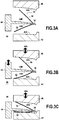
- FIGS. 3A to 3F illustrate the different stages of production by forging of the metallic structural reinforcement 18 from the preformed metal part 30 resulting from the above-mentioned steps by means of a form tool capable of forging at high temperature of this part.
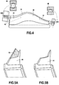
- This tooling is intended to bring the lateral wings 32, 34 and thus reduce the opening angle to obtain the desired final shape. It implements in a closed enclosure 40 (see figure 4 ) and at a temperature between 750 and 850 ° C, a first matrix 42, a movable central insert 44 and a second matrix 46.
- the first matrix is advantageously a fixed lower matrix and the second matrix a movable upper matrix without this provision being limiting, the important is to obtain a relative movement of approach of the first and second dies relative to the central insert.
- the movable central insert 44 being disposed in a first so-called high position, the preformed metal part 30 is first put in place on this insert until it comes into contact with the inner part of the nose 36 and it is then blocked at the ends for example by means of a connection having with respect to the frame (enclosure 40) of the shaped tool a recess of the first pin on the one hand, for example the trunnion 38A of lower blade, and a pivoting of the second trunnion, the trunnion 38B of upper blade on the other hand, to ensure a coaxiality of the trunnions while allowing a positioning isostatism.
- the figure 3B illustrates the next step of the method in which the movable central insert 44 and the movable upper die 46 are moved, simultaneously or not, to the fixed lower die 42 in a direction of movement 48A (vertical in the drawing) to engage the conformage the first lateral fin 32 by closing gradually, by bringing the insert with the lower die, the opening angle of the first lateral fin.
- the displacement is simultaneous, the displacement of the insert is advantageously guided by the displacement of the movable upper die.
- the displacement of the movable central insert 44 is stopped in a so-called intermediate position allowing a partial conformation of the first lateral fin 32 taken between this insert and the fixed lower die 42.
- the displacement of the movable upper die 46 becomes continues or begins according to whether respectively this movement has already begun or not, to engage the conformation of the second lateral fin 34 by closing gradually, by the bringing together this time of the upper die with the insert, the opening angle of this second lateral fin.
- the objective of this partial conformation being to avoid residual deformation and ruin of the tool, the degree of closure chosen will depend on various parameters including the forming temperature, the characteristics of the materials forming the tool and the workpiece.
- the displacement of the movable central insert 44 resumes in the direction 48A towards a so-called low end position, accompanied by the further movement of the movable upper die 46 in the same direction, proceed to the conformation (not more partial but total) simultaneous first and second lateral fins 32,34 which will then perfectly fit the inner contour of the tool shape.
- the facing faces of the movable central insert 44A and the lower die 42A are of course shaped to leave between them the only space necessary to receive the first lateral fin 32 of the preformed metal piece in its final form, that is, aligned with the nose 36.
- the upper wall 44B of the movable central insert and the lower wall 46A of the movable upper die have conformed facing faces to leave between them the only space necessary for the forming the second lateral fin 34 of the preformed metal part in its final form. In this total conformation position, it will be noted that the tool is kept closed on the workpiece for a few minutes to avoid any risk of elastic return of the workpiece.
- the preformed metal part 30 has the final Y shape of the metal structural reinforcement 18 with its two lateral flanks 24, 26 extending from its base 22 and having its required final opening angle. by the technical specifications. It will then only remain to proceed with the successive displacement of the mobile upper matrix 46 ( figure 3E ) and then the movable central insert 44 ( figure 3F ) in the common direction of displacement 48A (but in opposite directions to their previous movements) to allow the extraction (preferably hot) of this metal structural reinforcement, this extraction being effected in a direction perpendicular to this common direction.
- the central insert 44 shown in FIG. figure 4 with the piece 30 covering it, has at least two cutting areas 50, 52 at its two ends.
- the truncated portion 50 to overcome the undercut 49 appears more precisely at the Figure 5A while Figure 5B shows the central insert in its final form devoid of this missing part.
- a deposition of a protective layer of boron nitride on the movable central insert can be made beforehand to obtain better sliding and once extracted a polishing of the metallic structural reinforcement can also be achieved to obtain a better rendering.
Landscapes
- Engineering & Computer Science (AREA)
- Mechanical Engineering (AREA)
- General Engineering & Computer Science (AREA)
- Chemical & Material Sciences (AREA)
- Materials Engineering (AREA)
- Composite Materials (AREA)
- Architecture (AREA)
- Forging (AREA)
Claims (8)
- Schmiedeverfahren, das ein Formwerkzeug verwendet, welches für das Hochtemperaturschmieden eines vorgeformten Metallteils (30) geeignet ist, das in seiner endgültigen Form winkelige Verwindungshinterschneidungen (49) aufweist, wobei das Verfahren die folgenden Schritte umfasst:- Anordnen des vorgeformten Metallteils an einem beweglichen mittleren Einsatz (44) des Werkzeugs, der wenigstens zwei Abtrennbereiche zum Beseitigen der winkeligen Verwindungshinterschneidungen umfasst,- Festlegen des vorgeformten Metallteils in dem Werkzeug,- Gestaltung von seitlichen Flügeln (32, 34) des vorgeformten Metallteils in seiner endgültigen Form durch das Relativbewegen, in einer gemeinsamen Richtung (48A), eines ersten Gesenks (46) und des beweglichen mittleren Einsatzes zu einem zweiten Gesenk (42) hin,- Freilegen des vorgeformten Metallteils in endgültiger Form in einer einzigen Herausziehrichtung.
- Schmiedeverfahren nach Anspruch 1, dadurch gekennzeichnet, dass die wenigstens zwei Abtrennbereiche zwei abgestumpfte Teile (50, 52) umfassen, die an zwei Enden des beweglichen mittleren Einsatzes ausgebildet sind.
- Schmiedeverfahren nach Anspruch 1, dadurch gekennzeichnet, dass das Bewegen des beweglichen mittleren Einsatzes durch das Bewegen des ersten Gesenks geführt wird.
- Schmiedeverfahren nach Anspruch 1, dadurch gekennzeichnet, dass die einzige Herausziehrichtung zu der gemeinsamen Bewegungsrichtung senkrecht verläuft.
- Schmiedeverfahren nach Anspruch 1, dadurch gekennzeichnet, dass das vorgeformte Metallteil an jedem seiner beiden Enden einen Zapfen (38A, 38B) aufweist und das Festlegen des vorgeformten Metallteils in dem Werkzeug durch Einfügen von einem der beiden Zapfen und durch Verschwenken des anderen der beiden Zapfen erreicht wird.
- Formwerkzeug, geeignet für das Hochtemperaturschmieden eines vorgeformten Metallteils (30), das in seiner endgültigen Form winkelige Verwindungshinterschneidungen (49) aufweist, in einem Gehäuse (40), wobei das Formwerkzeug umfasst:• ein erstes Gesenk (42) zum Formen eines (32) seitlichen Flügels des vorgeformten Metallteils in seiner endgültigen Form,• einen beweglichen mittleren Einsatz (44), an dem das vorgeformte Metallteil angeordnet wird, wobei das vorgeformte Metallteil ferner in dem Gehäuse des Formwerkzeugs festgelegt wird,• ein zweites Gesenk (46) zum Formen eines weiteren (34) seitlichen Flügels des vorgeformten Metallteils in seiner endgültigen Form,wobei der bewegliche mittlere Einsatz wenigstens zwei Abtrennbereiche (50, 52) umfasst, um die winkeligen Verwindungshinterschneidungen zu entfernen und um somit ein Freilegen des vorgeformten Metallteils in endgültiger Form in einer einzigen Herausziehrichtung zu ermöglichen.
- Formwerkzeug nach Anspruch 6, dadurch gekennzeichnet, dass der bewegliche mittlere Einsatz zwei abgestumpfte Teile (50, 52) an seinen beiden Enden umfasst.
- Formwerkzeug nach Anspruch 6, dadurch gekennzeichnet, dass das erste Gesenk ein festes Untergesenk und das zweite Gesenk ein bewegliches Obergesenk ist.
Applications Claiming Priority (2)
| Application Number | Priority Date | Filing Date | Title |
|---|---|---|---|
| FR1551403A FR3032898B1 (fr) | 2015-02-19 | 2015-02-19 | Procede de forgeage a haute temperature d'une piece metallique preformee |
| PCT/FR2016/050283 WO2016132044A1 (fr) | 2015-02-19 | 2016-02-09 | Procédé de forgeage a haute température d'une pièce métallique préformée et outillage de forme apte au forgeage |
Publications (2)
| Publication Number | Publication Date |
|---|---|
| EP3259083A1 EP3259083A1 (de) | 2017-12-27 |
| EP3259083B1 true EP3259083B1 (de) | 2019-04-03 |
Family
ID=53200120
Family Applications (1)
| Application Number | Title | Priority Date | Filing Date |
|---|---|---|---|
| EP16707886.4A Active EP3259083B1 (de) | 2015-02-19 | 2016-02-09 | Verfahren zum hochtemperaturschmieden eines vorgeformten metallteils und zum schmieden geeignete formgebungsausrüstung |
Country Status (5)
| Country | Link |
|---|---|
| US (1) | US10668523B2 (de) |
| EP (1) | EP3259083B1 (de) |
| CN (1) | CN107249776B (de) |
| FR (1) | FR3032898B1 (de) |
| WO (1) | WO2016132044A1 (de) |
Families Citing this family (2)
| Publication number | Priority date | Publication date | Assignee | Title |
|---|---|---|---|---|
| CN112238195B (zh) * | 2020-10-23 | 2022-07-26 | 浙江三新科技有限公司 | 一种风机用翼型叶片的制造方法 |
| FR3138668B1 (fr) * | 2022-08-02 | 2024-07-05 | Safran Aircraft Engines | Aube comprenant un renfort métallique provisoire |
Family Cites Families (13)
| Publication number | Priority date | Publication date | Assignee | Title |
|---|---|---|---|---|
| US2544447A (en) * | 1944-11-24 | 1951-03-06 | Curtiss Wright Corp | Apparatus for producing shaped sections |
| US2799919A (en) * | 1951-11-01 | 1957-07-23 | Gen Motors Corp | Sheet metal blade and manufacture |
| US3057393A (en) * | 1957-06-03 | 1962-10-09 | Stalker Corp | Fabrication of blade blanks |
| US5168741A (en) * | 1990-11-20 | 1992-12-08 | Braunheim Stephen T | Method for forming a leading edge cover for jet engine blades |
| US5694683A (en) * | 1993-04-20 | 1997-12-09 | Chromalloy Gas Turbine Corporation | Hot forming process |
| FR2906320B1 (fr) | 2006-09-26 | 2008-12-26 | Snecma Sa | Aube composite de turbomachine a renfort metallique |
| US7805839B2 (en) * | 2007-12-31 | 2010-10-05 | Turbine Engine Components Technologies Corporation | Method of manufacturing a turbine fan blade |
| RU2012127372A (ru) * | 2009-11-30 | 2014-01-10 | Снекма | Способ выполнения металлического усилительного элемента лопатки турбомашины |
| FR2961866B1 (fr) | 2010-06-24 | 2014-09-26 | Snecma | Procede de realisation d’un renfort metallique d’aube de turbomachine |
| FR2965496B1 (fr) | 2010-09-30 | 2013-07-12 | Snecma | Outillage de forme « multi-effets » apte au formage a haute temperature. |
| RU2570254C2 (ru) * | 2011-03-01 | 2015-12-10 | Снекма | Способ изготовления металлической части, такой как усиление лопатки турбинного двигателя |
| FR2978926B1 (fr) * | 2011-08-11 | 2014-05-09 | Snecma | Dispositif pour la mise en forme d'une tole par matricage |
| FR3009982B1 (fr) * | 2013-09-02 | 2016-02-19 | Snecma | Procede de forgeage a haute temperature d'un renfort metallique d'aube |
-
2015
- 2015-02-19 FR FR1551403A patent/FR3032898B1/fr active Active
-
2016
- 2016-02-09 CN CN201680010822.5A patent/CN107249776B/zh active Active
- 2016-02-09 WO PCT/FR2016/050283 patent/WO2016132044A1/fr not_active Ceased
- 2016-02-09 US US15/552,149 patent/US10668523B2/en active Active
- 2016-02-09 EP EP16707886.4A patent/EP3259083B1/de active Active
Non-Patent Citations (1)
| Title |
|---|
| None * |
Also Published As
| Publication number | Publication date |
|---|---|
| FR3032898A1 (fr) | 2016-08-26 |
| EP3259083A1 (de) | 2017-12-27 |
| WO2016132044A1 (fr) | 2016-08-25 |
| US10668523B2 (en) | 2020-06-02 |
| US20180043423A1 (en) | 2018-02-15 |
| CN107249776B (zh) | 2019-05-14 |
| CN107249776A (zh) | 2017-10-13 |
| FR3032898B1 (fr) | 2017-03-10 |
Similar Documents
| Publication | Publication Date | Title |
|---|---|---|
| EP2507010B1 (de) | Verfahren zur herstellung einer metallverstärkung für eine turbomaschinenschaufel | |
| EP2585721B1 (de) | Verfahren zur fertigung des metallischen schutzschildes einer turbomaschinenschaufel | |
| EP2547489B1 (de) | Verfahren zur herstellung einer metallverstärkung für eine turbomaschinenschaufel | |
| EP2516107B1 (de) | Verfahren zur herstellung einer metallverstärkung für ein turbinenmotorblatt | |
| EP3041619B1 (de) | Verfahren zum hochtemperaturformen einer metallklingenverstärkung | |
| EP2681345B1 (de) | Verfahren zur herstellung eines metallbauteils wie einer turbomaschinenschaufelverstärkung | |
| EP2838692B1 (de) | Verfahren zur erzeugung eines metallischen verstärkungsstücks zum schützen einer vorderkante oder einer hinterkante einer kompositschaufel und entsprechendes metallisches verstärkungsstück | |
| EP2681004B1 (de) | Verfahren zur herstellung eines metallbauteils wie einer turbomaschinenschaufelkantenverstärkung | |
| EP2627809B1 (de) | Verfahren zur herstellung einer metallfaserstruktur durch weben | |
| FR2929149A1 (fr) | Procede de fabrication d'une aube creuse | |
| FR2970891A1 (fr) | Procede de realisation d’une piece metallique renforcee, telle qu’un renfort d’aube de turbomachine | |
| EP2621648A2 (de) | Multieffekt-formwerkzeug für hochtemperaturformen | |
| EP3259083B1 (de) | Verfahren zum hochtemperaturschmieden eines vorgeformten metallteils und zum schmieden geeignete formgebungsausrüstung | |
| EP3898073A1 (de) | Verfahren zur herstellung einer metallverstärkung für eine turbomaschinenschaufel | |
| FR2972127A1 (fr) | Procede de realisation d'une piece metallique telle qu'un renfort d'aube de turbomachine | |
| WO2012117202A1 (fr) | Procede de realisation d'une piece metallique telle qu'un renfort d'aube de turbomachine | |
| FR2972126A1 (fr) | Procede de realisation d'une piece metallique telle qu'un renfort d'aube de turbomachine | |
| FR2976204A1 (fr) | Procede d'usinage final d'un insert metallique pour la protection d'un bord d'attaque en materiau composite | |
| FR2972128A1 (fr) | Procede de realisation d'une piece metallique telle qu'un renfort de turbomachine |
Legal Events
| Date | Code | Title | Description |
|---|---|---|---|
| STAA | Information on the status of an ep patent application or granted ep patent |
Free format text: STATUS: THE INTERNATIONAL PUBLICATION HAS BEEN MADE |
|
| PUAI | Public reference made under article 153(3) epc to a published international application that has entered the european phase |
Free format text: ORIGINAL CODE: 0009012 |
|
| STAA | Information on the status of an ep patent application or granted ep patent |
Free format text: STATUS: REQUEST FOR EXAMINATION WAS MADE |
|
| 17P | Request for examination filed |
Effective date: 20170808 |
|
| AK | Designated contracting states |
Kind code of ref document: A1 Designated state(s): AL AT BE BG CH CY CZ DE DK EE ES FI FR GB GR HR HU IE IS IT LI LT LU LV MC MK MT NL NO PL PT RO RS SE SI SK SM TR |
|
| AX | Request for extension of the european patent |
Extension state: BA ME |
|
| DAV | Request for validation of the european patent (deleted) | ||
| DAX | Request for extension of the european patent (deleted) | ||
| GRAP | Despatch of communication of intention to grant a patent |
Free format text: ORIGINAL CODE: EPIDOSNIGR1 |
|
| STAA | Information on the status of an ep patent application or granted ep patent |
Free format text: STATUS: GRANT OF PATENT IS INTENDED |
|
| INTG | Intention to grant announced |
Effective date: 20181016 |
|
| D17P | Request for examination filed (deleted) | ||
| GRAS | Grant fee paid |
Free format text: ORIGINAL CODE: EPIDOSNIGR3 |
|
| R17P | Request for examination filed (corrected) |
Effective date: 20170808 |
|
| RBV | Designated contracting states (corrected) |
Designated state(s): AL AT BE BG CH CY CZ DE DK EE ES FI FR GB GR HR HU IE IS IT LI LT LU LV MC MK MT NL NO PL PT RO RS SE SI SK SM TR |
|
| GRAA | (expected) grant |
Free format text: ORIGINAL CODE: 0009210 |
|
| STAA | Information on the status of an ep patent application or granted ep patent |
Free format text: STATUS: THE PATENT HAS BEEN GRANTED |
|
| AK | Designated contracting states |
Kind code of ref document: B1 Designated state(s): AL AT BE BG CH CY CZ DE DK EE ES FI FR GB GR HR HU IE IS IT LI LT LU LV MC MK MT NL NO PL PT RO RS SE SI SK SM TR |
|
| REG | Reference to a national code |
Ref country code: GB Ref legal event code: FG4D Free format text: NOT ENGLISH |
|
| REG | Reference to a national code |
Ref country code: CH Ref legal event code: EP Ref country code: AT Ref legal event code: REF Ref document number: 1115096 Country of ref document: AT Kind code of ref document: T Effective date: 20190415 |
|
| REG | Reference to a national code |
Ref country code: DE Ref legal event code: R096 Ref document number: 602016011875 Country of ref document: DE |
|
| REG | Reference to a national code |
Ref country code: IE Ref legal event code: FG4D Free format text: LANGUAGE OF EP DOCUMENT: FRENCH |
|
| REG | Reference to a national code |
Ref country code: SE Ref legal event code: TRGR |
|
| REG | Reference to a national code |
Ref country code: NL Ref legal event code: MP Effective date: 20190403 |
|
| REG | Reference to a national code |
Ref country code: LT Ref legal event code: MG4D |
|
| REG | Reference to a national code |
Ref country code: AT Ref legal event code: MK05 Ref document number: 1115096 Country of ref document: AT Kind code of ref document: T Effective date: 20190403 |
|
| PG25 | Lapsed in a contracting state [announced via postgrant information from national office to epo] |
Ref country code: NL Free format text: LAPSE BECAUSE OF FAILURE TO SUBMIT A TRANSLATION OF THE DESCRIPTION OR TO PAY THE FEE WITHIN THE PRESCRIBED TIME-LIMIT Effective date: 20190403 |
|
| PG25 | Lapsed in a contracting state [announced via postgrant information from national office to epo] |
Ref country code: CZ Free format text: LAPSE BECAUSE OF FAILURE TO SUBMIT A TRANSLATION OF THE DESCRIPTION OR TO PAY THE FEE WITHIN THE PRESCRIBED TIME-LIMIT Effective date: 20190403 Ref country code: ES Free format text: LAPSE BECAUSE OF FAILURE TO SUBMIT A TRANSLATION OF THE DESCRIPTION OR TO PAY THE FEE WITHIN THE PRESCRIBED TIME-LIMIT Effective date: 20190403 Ref country code: LT Free format text: LAPSE BECAUSE OF FAILURE TO SUBMIT A TRANSLATION OF THE DESCRIPTION OR TO PAY THE FEE WITHIN THE PRESCRIBED TIME-LIMIT Effective date: 20190403 Ref country code: HR Free format text: LAPSE BECAUSE OF FAILURE TO SUBMIT A TRANSLATION OF THE DESCRIPTION OR TO PAY THE FEE WITHIN THE PRESCRIBED TIME-LIMIT Effective date: 20190403 Ref country code: FI Free format text: LAPSE BECAUSE OF FAILURE TO SUBMIT A TRANSLATION OF THE DESCRIPTION OR TO PAY THE FEE WITHIN THE PRESCRIBED TIME-LIMIT Effective date: 20190403 Ref country code: AL Free format text: LAPSE BECAUSE OF FAILURE TO SUBMIT A TRANSLATION OF THE DESCRIPTION OR TO PAY THE FEE WITHIN THE PRESCRIBED TIME-LIMIT Effective date: 20190403 Ref country code: PT Free format text: LAPSE BECAUSE OF FAILURE TO SUBMIT A TRANSLATION OF THE DESCRIPTION OR TO PAY THE FEE WITHIN THE PRESCRIBED TIME-LIMIT Effective date: 20190803 Ref country code: NO Free format text: LAPSE BECAUSE OF FAILURE TO SUBMIT A TRANSLATION OF THE DESCRIPTION OR TO PAY THE FEE WITHIN THE PRESCRIBED TIME-LIMIT Effective date: 20190703 |
|
| PG25 | Lapsed in a contracting state [announced via postgrant information from national office to epo] |
Ref country code: LV Free format text: LAPSE BECAUSE OF FAILURE TO SUBMIT A TRANSLATION OF THE DESCRIPTION OR TO PAY THE FEE WITHIN THE PRESCRIBED TIME-LIMIT Effective date: 20190403 Ref country code: PL Free format text: LAPSE BECAUSE OF FAILURE TO SUBMIT A TRANSLATION OF THE DESCRIPTION OR TO PAY THE FEE WITHIN THE PRESCRIBED TIME-LIMIT Effective date: 20190403 Ref country code: GR Free format text: LAPSE BECAUSE OF FAILURE TO SUBMIT A TRANSLATION OF THE DESCRIPTION OR TO PAY THE FEE WITHIN THE PRESCRIBED TIME-LIMIT Effective date: 20190704 Ref country code: RS Free format text: LAPSE BECAUSE OF FAILURE TO SUBMIT A TRANSLATION OF THE DESCRIPTION OR TO PAY THE FEE WITHIN THE PRESCRIBED TIME-LIMIT Effective date: 20190403 Ref country code: BG Free format text: LAPSE BECAUSE OF FAILURE TO SUBMIT A TRANSLATION OF THE DESCRIPTION OR TO PAY THE FEE WITHIN THE PRESCRIBED TIME-LIMIT Effective date: 20190703 |
|
| PG25 | Lapsed in a contracting state [announced via postgrant information from national office to epo] |
Ref country code: AT Free format text: LAPSE BECAUSE OF FAILURE TO SUBMIT A TRANSLATION OF THE DESCRIPTION OR TO PAY THE FEE WITHIN THE PRESCRIBED TIME-LIMIT Effective date: 20190403 Ref country code: IS Free format text: LAPSE BECAUSE OF FAILURE TO SUBMIT A TRANSLATION OF THE DESCRIPTION OR TO PAY THE FEE WITHIN THE PRESCRIBED TIME-LIMIT Effective date: 20190803 |
|
| REG | Reference to a national code |
Ref country code: DE Ref legal event code: R097 Ref document number: 602016011875 Country of ref document: DE |
|
| PG25 | Lapsed in a contracting state [announced via postgrant information from national office to epo] |
Ref country code: RO Free format text: LAPSE BECAUSE OF FAILURE TO SUBMIT A TRANSLATION OF THE DESCRIPTION OR TO PAY THE FEE WITHIN THE PRESCRIBED TIME-LIMIT Effective date: 20190403 Ref country code: EE Free format text: LAPSE BECAUSE OF FAILURE TO SUBMIT A TRANSLATION OF THE DESCRIPTION OR TO PAY THE FEE WITHIN THE PRESCRIBED TIME-LIMIT Effective date: 20190403 Ref country code: DK Free format text: LAPSE BECAUSE OF FAILURE TO SUBMIT A TRANSLATION OF THE DESCRIPTION OR TO PAY THE FEE WITHIN THE PRESCRIBED TIME-LIMIT Effective date: 20190403 Ref country code: SK Free format text: LAPSE BECAUSE OF FAILURE TO SUBMIT A TRANSLATION OF THE DESCRIPTION OR TO PAY THE FEE WITHIN THE PRESCRIBED TIME-LIMIT Effective date: 20190403 |
|
| PLBE | No opposition filed within time limit |
Free format text: ORIGINAL CODE: 0009261 |
|
| STAA | Information on the status of an ep patent application or granted ep patent |
Free format text: STATUS: NO OPPOSITION FILED WITHIN TIME LIMIT |
|
| PG25 | Lapsed in a contracting state [announced via postgrant information from national office to epo] |
Ref country code: SM Free format text: LAPSE BECAUSE OF FAILURE TO SUBMIT A TRANSLATION OF THE DESCRIPTION OR TO PAY THE FEE WITHIN THE PRESCRIBED TIME-LIMIT Effective date: 20190403 |
|
| 26N | No opposition filed |
Effective date: 20200106 |
|
| PG25 | Lapsed in a contracting state [announced via postgrant information from national office to epo] |
Ref country code: TR Free format text: LAPSE BECAUSE OF FAILURE TO SUBMIT A TRANSLATION OF THE DESCRIPTION OR TO PAY THE FEE WITHIN THE PRESCRIBED TIME-LIMIT Effective date: 20190403 |
|
| PG25 | Lapsed in a contracting state [announced via postgrant information from national office to epo] |
Ref country code: SI Free format text: LAPSE BECAUSE OF FAILURE TO SUBMIT A TRANSLATION OF THE DESCRIPTION OR TO PAY THE FEE WITHIN THE PRESCRIBED TIME-LIMIT Effective date: 20190403 |
|
| REG | Reference to a national code |
Ref country code: CH Ref legal event code: PL |
|
| REG | Reference to a national code |
Ref country code: BE Ref legal event code: MM Effective date: 20200229 |
|
| PG25 | Lapsed in a contracting state [announced via postgrant information from national office to epo] |
Ref country code: LU Free format text: LAPSE BECAUSE OF NON-PAYMENT OF DUE FEES Effective date: 20200209 Ref country code: MC Free format text: LAPSE BECAUSE OF FAILURE TO SUBMIT A TRANSLATION OF THE DESCRIPTION OR TO PAY THE FEE WITHIN THE PRESCRIBED TIME-LIMIT Effective date: 20190403 |
|
| PG25 | Lapsed in a contracting state [announced via postgrant information from national office to epo] |
Ref country code: LI Free format text: LAPSE BECAUSE OF NON-PAYMENT OF DUE FEES Effective date: 20200229 Ref country code: CH Free format text: LAPSE BECAUSE OF NON-PAYMENT OF DUE FEES Effective date: 20200229 |
|
| PG25 | Lapsed in a contracting state [announced via postgrant information from national office to epo] |
Ref country code: IE Free format text: LAPSE BECAUSE OF NON-PAYMENT OF DUE FEES Effective date: 20200209 |
|
| PG25 | Lapsed in a contracting state [announced via postgrant information from national office to epo] |
Ref country code: BE Free format text: LAPSE BECAUSE OF NON-PAYMENT OF DUE FEES Effective date: 20200229 |
|
| PG25 | Lapsed in a contracting state [announced via postgrant information from national office to epo] |
Ref country code: MT Free format text: LAPSE BECAUSE OF FAILURE TO SUBMIT A TRANSLATION OF THE DESCRIPTION OR TO PAY THE FEE WITHIN THE PRESCRIBED TIME-LIMIT Effective date: 20190403 Ref country code: CY Free format text: LAPSE BECAUSE OF FAILURE TO SUBMIT A TRANSLATION OF THE DESCRIPTION OR TO PAY THE FEE WITHIN THE PRESCRIBED TIME-LIMIT Effective date: 20190403 |
|
| PG25 | Lapsed in a contracting state [announced via postgrant information from national office to epo] |
Ref country code: MK Free format text: LAPSE BECAUSE OF FAILURE TO SUBMIT A TRANSLATION OF THE DESCRIPTION OR TO PAY THE FEE WITHIN THE PRESCRIBED TIME-LIMIT Effective date: 20190403 |
|
| PGFP | Annual fee paid to national office [announced via postgrant information from national office to epo] |
Ref country code: SE Payment date: 20240123 Year of fee payment: 9 |
|
| PGFP | Annual fee paid to national office [announced via postgrant information from national office to epo] |
Ref country code: DE Payment date: 20250122 Year of fee payment: 10 |
|
| PGFP | Annual fee paid to national office [announced via postgrant information from national office to epo] |
Ref country code: FR Payment date: 20250121 Year of fee payment: 10 |
|
| PGFP | Annual fee paid to national office [announced via postgrant information from national office to epo] |
Ref country code: GB Payment date: 20250123 Year of fee payment: 10 Ref country code: IT Payment date: 20250121 Year of fee payment: 10 |
|
| REG | Reference to a national code |
Ref country code: SE Ref legal event code: EUG |