EP3258754A1 - Rack system and slide rail assemblies thereof - Google Patents
Rack system and slide rail assemblies thereof Download PDFInfo
- Publication number
- EP3258754A1 EP3258754A1 EP16207077.5A EP16207077A EP3258754A1 EP 3258754 A1 EP3258754 A1 EP 3258754A1 EP 16207077 A EP16207077 A EP 16207077A EP 3258754 A1 EP3258754 A1 EP 3258754A1
- Authority
- EP
- European Patent Office
- Prior art keywords
- rail
- slide rail
- feature
- rail assembly
- rack
- Prior art date
- Legal status (The legal status is an assumption and is not a legal conclusion. Google has not performed a legal analysis and makes no representation as to the accuracy of the status listed.)
- Granted
Links
Images





Classifications
-
- H—ELECTRICITY
- H05—ELECTRIC TECHNIQUES NOT OTHERWISE PROVIDED FOR
- H05K—PRINTED CIRCUITS; CASINGS OR CONSTRUCTIONAL DETAILS OF ELECTRIC APPARATUS; MANUFACTURE OF ASSEMBLAGES OF ELECTRICAL COMPONENTS
- H05K7/00—Constructional details common to different types of electric apparatus
- H05K7/14—Mounting supporting structure in casing or on frame or rack
- H05K7/1421—Drawers for printed circuit boards
-
- A—HUMAN NECESSITIES
- A47—FURNITURE; DOMESTIC ARTICLES OR APPLIANCES; COFFEE MILLS; SPICE MILLS; SUCTION CLEANERS IN GENERAL
- A47B—TABLES; DESKS; OFFICE FURNITURE; CABINETS; DRAWERS; GENERAL DETAILS OF FURNITURE
- A47B88/00—Drawers for tables, cabinets or like furniture; Guides for drawers
- A47B88/40—Sliding drawers; Slides or guides therefor
- A47B88/49—Sliding drawers; Slides or guides therefor with double extensible guides or parts
- A47B88/493—Sliding drawers; Slides or guides therefor with double extensible guides or parts with rollers, ball bearings, wheels, or the like
-
- H—ELECTRICITY
- H05—ELECTRIC TECHNIQUES NOT OTHERWISE PROVIDED FOR
- H05K—PRINTED CIRCUITS; CASINGS OR CONSTRUCTIONAL DETAILS OF ELECTRIC APPARATUS; MANUFACTURE OF ASSEMBLAGES OF ELECTRICAL COMPONENTS
- H05K7/00—Constructional details common to different types of electric apparatus
- H05K7/14—Mounting supporting structure in casing or on frame or rack
- H05K7/1485—Servers; Data center rooms, e.g. 19-inch computer racks
- H05K7/1488—Cabinets therefor, e.g. chassis or racks or mechanical interfaces between blades and support structures
- H05K7/1489—Cabinets therefor, e.g. chassis or racks or mechanical interfaces between blades and support structures characterized by the mounting of blades therein, e.g. brackets, rails, trays
-
- H—ELECTRICITY
- H05—ELECTRIC TECHNIQUES NOT OTHERWISE PROVIDED FOR
- H05K—PRINTED CIRCUITS; CASINGS OR CONSTRUCTIONAL DETAILS OF ELECTRIC APPARATUS; MANUFACTURE OF ASSEMBLAGES OF ELECTRICAL COMPONENTS
- H05K7/00—Constructional details common to different types of electric apparatus
- H05K7/14—Mounting supporting structure in casing or on frame or rack
- H05K7/1485—Servers; Data center rooms, e.g. 19-inch computer racks
- H05K7/1488—Cabinets therefor, e.g. chassis or racks or mechanical interfaces between blades and support structures
- H05K7/1491—Cabinets therefor, e.g. chassis or racks or mechanical interfaces between blades and support structures having cable management arrangements
Definitions
- the present invention relates to a rack system and its slide rail assemblies. More particularly, the invention relates to a rack system whose slide rail assemblies are configured to be mounted with a relatively wide chassis.
- Haney discloses a rack with four posts and a pair of slide rail assemblies mounted on the rack in order to support a chassis.
- EIA Electronic Industries Association
- the distance between the inner sides of two corresponding posts of such a rack is generally 450 mm.
- chassis manufacturers tend to design and produce chassis of increasing width, and this trend has reduced the slide rail mounting space between a chassis and its rack, if not compromising the arrangement of slide rails.
- the present invention was conceived in response to this current market trend.
- Another objective of the present invention is to provide a slide rail assembly to which a chassis can be mounted and which can be connected with a cable management arm for arranging the cables behind the chassis.
- Yet another objective of the present invention is to provide a slide rail assembly to which a chassis can be mounted securely.
- a rack system includes a rack, a chassis, a first slide rail assembly, and a second slide rail assembly.
- the rack includes a first post and a second post.
- the first post and the second post define a width therebetween.
- the chassis has a first lateral side and a second lateral side.
- the first slide rail assembly and the second slide rail assembly are mounted on the first post and the second post of the rack respectively.
- the first lateral side of the chassis is mounted to the first slide rail assembly while the second lateral side of the chassis is mounted to the second slide rail assembly.
- Each of the slide rail assemblies includes a first rail, a second rail, and a third rail.
- Each first rail has a rail-thickness-wise cross section, which is outside the space in which the width defined by the rack extends.
- the second rails and the third rails are within the space in which the width defined by the rack extends.
- a slide rail assembly includes a first rail, a second rail, a third rail, and an extension member.
- the first rail has a first channel.
- the second rail can be displaced with respect to the first rail.
- the third rail is movably provided between the first channel of the first rail and the second rail.
- the extension member is connected to the first rail and has a surface lying substantially in the same plane as an outer surface of the third rail.
- a slide rail assembly includes a first rail, a second rail, a third rail, and an extension member.
- the first rail has a first channel.
- the second rail can be displaced with respect to the first rail.
- the third rail is movably provided between the first channel of the first rail and the second rail and has a second channel.
- the extension member is connected to the first rail and has a thickness not greater than the width of the second channel of the third rail.
- a slide rail assembly to be mounted with a chassis includes a first rail and a second rail.
- the second rail can be displaced with respect to the first rail and includes a first feature and a second feature different from the first feature.
- the chassis includes a first mounting feature and a second mounting feature to be mounted respectively to the first feature and the second feature of the second rail.
- the rack includes a third post and a fourth post, which correspond to the first post and the second post respectively in order for the first slide rail assembly to be mounted on the first post and the third post and for the second slide rail assembly to be mounted on the second post and the fourth post.
- the rack system further includes a cable management arm and an extension member.
- the cable management arm is mounted to the first slide rail assembly and includes a first arm section and a second arm section connected to and movable with respect to the first arm section.
- the extension member is connected to one of the first rail of the first slide rail assembly and the first post of the rack.
- the first arm section of the cable management arm is mounted to the extension member while the second arm section of the cable management arm is mounted to the second rail of the first slide rail assembly.
- the extension member has a thickness-wise cross section within the space in which the width defined by the rack extends.
- the second rail of each slide rail assembly includes a first feature and a second feature different from the first feature
- the chassis includes a first mounting feature and a second mounting feature to be mounted respectively to the first feature and the second feature.
- the first feature and the second feature of the second rail of each slide rail assembly are a first hole and a first projection respectively
- the first mounting feature and the second mounting feature of the chassis are respectively a second projection to be mounted to the first hole and a second hole to be mounted to the first projection.
- the extension member extends from the first rail.
- the rack system in an embodiment of the present invention includes a slide rail unit 10 adapted for mounting a chassis 12 to a rack 14.
- the rack 14 at least includes a first post 16a and a second post 16b.
- the first post 16a and the second post 16b define a first width W1 therebetween.
- the chassis 12 has a first lateral side 18a and a second lateral side 18b.
- the slide rail unit 10 includes a first slide rail assembly 20 and a second slide rail assembly 22, which are mounted on the first post 16a and the second post 16b of the rack 14 respectively.
- the first lateral side 18a and the second lateral side 18b of the chassis 12 are mounted to the first slide rail assembly 20 and the second slide rail assembly 22 respectively.
- the rack 14 further includes a third post 16c and a fourth post 16d, which correspond to the first post 16a and the second post 16b respectively so that the first slide rail assembly 20 can be mounted on the first post 16a and the third post 16c while the second slide rail assembly 22 can be mounted on the second post 16b and the fourth post 16d.
- the first slide rail assembly 20 includes a first rail 24, a second rail 26, and a third rail 28.
- the first rail 24 functions as a stationary rail and has a first channel 30.
- the second rail 26 at least includes a first feature 32 and a second feature 34 different from the first feature 32.
- the chassis 12 at least includes a first mounting feature 36 and a second mounting feature 38, which are configured to be mounted to the first feature 32 and the second feature 34 of the second rail 26 respectively.
- the first feature 32 of the second rail 26 is shaped as a first hole (e.g., a keyhole), and the second feature 34 is a first projection (e.g., a columnar fixing member with a T-shaped profile), to which the second mounting feature 38 can be mounted in a detachable manner.
- the second feature 34 may be provided at a first position P1 or a second positon P2 of the second rail 26, and the second mounting feature 38 is provided at a first mounting position M1 or a second mounting position M2 of the chassis 12 in order to be mounted to the second feature 34 as appropriate.
- the first mounting feature 36 of the chassis 12 is a second projection, e.g., a columnar fixing member to be mounted to the first feature 32 (e.g., the first hole) of the second rail 26.
- the second mounting feature 38 of the chassis 12 is shaped as a second hole, e.g., a keyhole to be mounted to the second feature 34 (e.g., the first projection) of the second rail 26.
- the third rail 28 is movably mounted between the first channel 30 of the first rail 24 and the second rail 26.
- the third rail 28 serves to increase the distance by which the second rail 26 can be extended with respect to the first rail 24.
- the third rail 28 has a second channel 31, in and along which the second rail 26 can be displaced.
- FIG. 4 and FIG. 5 show how the chassis 12 is mounted to the rack 14 via the first slide rail assembly 20 and the second slide rail assembly 22.
- the rail-thickness-wise cross section of the first rail 24 of each of the first slide rail assembly 20 and the second slide rail assembly 22 is outside the space in which the first width W1 defined by the rack 14 extends (hereinafter referred to as the extension space of the first width W1 for short) whereas the second rail 26 and the third rail 28 of each slide rail assembly 20 or 22 are within the extension space of the first width W1 of the rack 14.
- the second channel 31 of the third rail 28 has a second width W2.
- the present invention further includes an extension member 40 connected to the first rail 24 of the first slide rail assembly 20 and a cable management arm 42 mounted to the first slide rail assembly 20.
- the cable management arm 42 includes a first arm section 44 and a second arm section 46 connected to and also movable with respect to the first arm section 44.
- the first arm section 44 of the cable management arm 42 is mounted to the extension member 40 while the second arm section 46 of the cable management arm 42 is mounted to the second rail 26 of the first slide rail assembly 20.
- extension member 40 is provided with a first connecting feature 48 for detachable connection with the first arm section 44 of the cable management arm 42
- second rail 26 of the first slide rail assembly 20 is provided with a second connecting feature 50 for detachable connection with the second arm section 46 of the cable management arm 42.
- the cable management arm 42 performs cable management by having its first arm section 44 connected to a fixed position (i.e., the extension member 40) and its second arm section 46 connected to a movable position (i.e., the second rail 26 of the first slide rail assembly 20).
- a fixed position i.e., the extension member 40
- a movable position i.e., the second rail 26 of the first slide rail assembly 20.
- FIG. 7 shows how the first slide rail assembly 20 mounts the chassis 12 to the rack 14.
- the length of the third rail 28 does not extend beyond the first post 16a of the rack 14.
- the extension member 40 can be connected (either fixedly or by mechanical engagement) to the first rail 24 of the first slide rail assembly 20, or the extension member 40 can be connected (either fixedly or by mechanical engagement) to the first post 16a of the rack 14.
- the extension member 40 has a surface 52 lying substantially in the same plane as an outer surface 54 of the third rail 28.
- the thickness-wise cross section of the extension member 40 is within the extension space of the first width W1 of the rack 14, or the thickness T of the extension member 40 is not greater than the second width W2 of the second channel 31 of the third rail 28 (see FIG. 5 ).
- the extension member 40 extends the length of the first rail 24, provides a fixed position to which the cable management arm 42 can be connected, but does not interfere with displacement of the second rail 26 with respect to the first rail 24. According to this arrangement, referring back to FIG.
- the first arm section 44 of the cable management arm 42 can be connected to the extension member 40 (which serves as a fixed position), and the second arm section 46 of the cable management arm 42 can be connected to the second rail 26 (which serves as a movable position), in order for the cable management arm 42 to be extended or folded up (see FIG. 1 ) as needed.
- the extension member 56 extends from the first rail 24.
Landscapes
- Engineering & Computer Science (AREA)
- Microelectronics & Electronic Packaging (AREA)
- Computer Hardware Design (AREA)
- General Engineering & Computer Science (AREA)
- Drawers Of Furniture (AREA)
- Bearings For Parts Moving Linearly (AREA)
Abstract
Description
- The present invention relates to a rack system and its slide rail assemblies. More particularly, the invention relates to a rack system whose slide rail assemblies are configured to be mounted with a relatively wide chassis.
- In
US Utility Patent No. 6,220,456 B1, Jensen et al. disclose a rack with two posts for supporting at least one chassis. - In
US Utility Patent No. 6,974,037 B2, Haney discloses a rack with four posts and a pair of slide rail assemblies mounted on the rack in order to support a chassis. According to EIA (Electronic Industries Association) standards, the distance between the inner sides of two corresponding posts of such a rack is generally 450 mm. Recently, however, chassis manufacturers tend to design and produce chassis of increasing width, and this trend has reduced the slide rail mounting space between a chassis and its rack, if not compromising the arrangement of slide rails. The present invention was conceived in response to this current market trend. - It is an objective of the present invention to provide a rack system that allows a relatively wide chassis to be mounted to a rack via a pair of slide rail assemblies.
- Another objective of the present invention is to provide a slide rail assembly to which a chassis can be mounted and which can be connected with a cable management arm for arranging the cables behind the chassis.
- Yet another objective of the present invention is to provide a slide rail assembly to which a chassis can be mounted securely.
- According to one aspect of the present invention, a rack system includes a rack, a chassis, a first slide rail assembly, and a second slide rail assembly. The rack includes a first post and a second post. The first post and the second post define a width therebetween. The chassis has a first lateral side and a second lateral side. The first slide rail assembly and the second slide rail assembly are mounted on the first post and the second post of the rack respectively. The first lateral side of the chassis is mounted to the first slide rail assembly while the second lateral side of the chassis is mounted to the second slide rail assembly. Each of the slide rail assemblies includes a first rail, a second rail, and a third rail. Each first rail has a rail-thickness-wise cross section, which is outside the space in which the width defined by the rack extends. The second rails and the third rails, on the other hand, are within the space in which the width defined by the rack extends.
- According to another aspect of the present invention, a slide rail assembly includes a first rail, a second rail, a third rail, and an extension member. The first rail has a first channel. The second rail can be displaced with respect to the first rail. The third rail is movably provided between the first channel of the first rail and the second rail. The extension member is connected to the first rail and has a surface lying substantially in the same plane as an outer surface of the third rail.
- According to still another aspect of the present invention, a slide rail assembly includes a first rail, a second rail, a third rail, and an extension member. The first rail has a first channel. The second rail can be displaced with respect to the first rail. The third rail is movably provided between the first channel of the first rail and the second rail and has a second channel. The extension member is connected to the first rail and has a thickness not greater than the width of the second channel of the third rail.
- According to yet another aspect of the present invention, a slide rail assembly to be mounted with a chassis includes a first rail and a second rail. The second rail can be displaced with respect to the first rail and includes a first feature and a second feature different from the first feature. The chassis includes a first mounting feature and a second mounting feature to be mounted respectively to the first feature and the second feature of the second rail.
- Preferably, the rack includes a third post and a fourth post, which correspond to the first post and the second post respectively in order for the first slide rail assembly to be mounted on the first post and the third post and for the second slide rail assembly to be mounted on the second post and the fourth post.
- Preferably, the rack system further includes a cable management arm and an extension member. The cable management arm is mounted to the first slide rail assembly and includes a first arm section and a second arm section connected to and movable with respect to the first arm section. The extension member is connected to one of the first rail of the first slide rail assembly and the first post of the rack. The first arm section of the cable management arm is mounted to the extension member while the second arm section of the cable management arm is mounted to the second rail of the first slide rail assembly.
- Preferably, the extension member has a thickness-wise cross section within the space in which the width defined by the rack extends.
- Preferably, the second rail of each slide rail assembly includes a first feature and a second feature different from the first feature, and the chassis includes a first mounting feature and a second mounting feature to be mounted respectively to the first feature and the second feature.
- Preferably, the first feature and the second feature of the second rail of each slide rail assembly are a first hole and a first projection respectively, and the first mounting feature and the second mounting feature of the chassis are respectively a second projection to be mounted to the first hole and a second hole to be mounted to the first projection.
- Preferably, the extension member extends from the first rail.
-
-
FIG. 1 is a perspective view of the rack system in an embodiment of the present invention, showing the arrangement of a pair of slide rail assemblies, a chassis, and a cable management arm; -
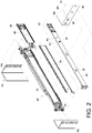
FIG. 2 is an exploded perspective view of a slide rail assembly in an embodiment of the present invention; -
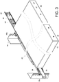
FIG. 3 is a perspective view showing how a chassis is mounted to a slide rail assembly in an embodiment of the present invention; -
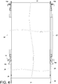
FIG. 4 is a top view showing a chassis mounted on a rack in an embodiment of the present invention; -
FIG. 5 is a sectional view showing how a pair of slide rail assemblies are mounted to a rack in an embodiment of the present invention; -
FIG. 6 is a top view showing a chassis pulled out of a rack in an embodiment of the present invention; -
FIG. 7 is a top sectional view showing the mounting arrangement of a slide rail assembly in relation to a chassis and a rack in an embodiment of the present invention; and -
FIG. 8 is a top sectional view showing how the extension member of a slide rail assembly in another embodiment of the present invention extends from the first rail. - Referring to
FIG. 1 , the rack system in an embodiment of the present invention includes aslide rail unit 10 adapted for mounting achassis 12 to arack 14. Therack 14 at least includes afirst post 16a and asecond post 16b. Thefirst post 16a and thesecond post 16b define a first width W1 therebetween. Thechassis 12 has a firstlateral side 18a and a secondlateral side 18b. Theslide rail unit 10 includes a firstslide rail assembly 20 and a secondslide rail assembly 22, which are mounted on thefirst post 16a and thesecond post 16b of therack 14 respectively. The firstlateral side 18a and the secondlateral side 18b of thechassis 12 are mounted to the firstslide rail assembly 20 and the secondslide rail assembly 22 respectively. In a preferred embodiment, therack 14 further includes athird post 16c and afourth post 16d, which correspond to thefirst post 16a and thesecond post 16b respectively so that the firstslide rail assembly 20 can be mounted on thefirst post 16a and thethird post 16c while the secondslide rail assembly 22 can be mounted on thesecond post 16b and thefourth post 16d. - As shown in
FIG. 2 andFIG. 3 , the firstslide rail assembly 20 includes afirst rail 24, asecond rail 26, and athird rail 28. Thefirst rail 24 functions as a stationary rail and has afirst channel 30. Thesecond rail 26 at least includes afirst feature 32 and asecond feature 34 different from thefirst feature 32. Thechassis 12 at least includes a first mountingfeature 36 and asecond mounting feature 38, which are configured to be mounted to thefirst feature 32 and thesecond feature 34 of thesecond rail 26 respectively. In a preferred embodiment, thefirst feature 32 of thesecond rail 26 is shaped as a first hole (e.g., a keyhole), and thesecond feature 34 is a first projection (e.g., a columnar fixing member with a T-shaped profile), to which the second mountingfeature 38 can be mounted in a detachable manner. In this embodiment, depending on the length of thechassis 12, thesecond feature 34 may be provided at a first position P1 or a second positon P2 of thesecond rail 26, and the second mountingfeature 38 is provided at a first mounting position M1 or a second mounting position M2 of thechassis 12 in order to be mounted to thesecond feature 34 as appropriate. Thefirst mounting feature 36 of thechassis 12 is a second projection, e.g., a columnar fixing member to be mounted to the first feature 32 (e.g., the first hole) of thesecond rail 26. Thesecond mounting feature 38 of thechassis 12 is shaped as a second hole, e.g., a keyhole to be mounted to the second feature 34 (e.g., the first projection) of thesecond rail 26. Thethird rail 28 is movably mounted between thefirst channel 30 of thefirst rail 24 and thesecond rail 26. Thethird rail 28 serves to increase the distance by which thesecond rail 26 can be extended with respect to thefirst rail 24. Thethird rail 28 has asecond channel 31, in and along which thesecond rail 26 can be displaced. -
FIG. 4 andFIG. 5 show how thechassis 12 is mounted to therack 14 via the firstslide rail assembly 20 and the secondslide rail assembly 22. The rail-thickness-wise cross section of thefirst rail 24 of each of the firstslide rail assembly 20 and the secondslide rail assembly 22 is outside the space in which the first width W1 defined by therack 14 extends (hereinafter referred to as the extension space of the first width W1 for short) whereas thesecond rail 26 and thethird rail 28 of eachslide rail assembly rack 14. This arrangement ensures that the width of thefirst rail 24 of eachslide rail assembly rack 14 but makes room for thechassis 12, allowing a relativelywide chassis 12 to be mounted to therack 14. Thesecond channel 31 of thethird rail 28 has a second width W2. - In a preferred embodiment, referring again to
FIG. 1 through FIG. 3 , the present invention further includes anextension member 40 connected to thefirst rail 24 of the firstslide rail assembly 20 and acable management arm 42 mounted to the firstslide rail assembly 20. Thecable management arm 42 includes afirst arm section 44 and asecond arm section 46 connected to and also movable with respect to thefirst arm section 44. Thefirst arm section 44 of thecable management arm 42 is mounted to theextension member 40 while thesecond arm section 46 of thecable management arm 42 is mounted to thesecond rail 26 of the firstslide rail assembly 20. More specifically, theextension member 40 is provided with a first connectingfeature 48 for detachable connection with thefirst arm section 44 of thecable management arm 42, and thesecond rail 26 of the firstslide rail assembly 20 is provided with a second connectingfeature 50 for detachable connection with thesecond arm section 46 of thecable management arm 42. - Referring to
FIG. 6 , it should be noted that thecable management arm 42 performs cable management by having itsfirst arm section 44 connected to a fixed position (i.e., the extension member 40) and itssecond arm section 46 connected to a movable position (i.e., thesecond rail 26 of the first slide rail assembly 20). When thechassis 12 is pulled out of therack 14 in the arrow direction F, thecable management arm 42 is driven by thechassis 12 to an extended state. -
FIG. 7 shows how the firstslide rail assembly 20 mounts thechassis 12 to therack 14. As depicted in the drawing, the length of thethird rail 28 does not extend beyond thefirst post 16a of therack 14. When there is a need to arrange the cables at the rear end of thechassis 12, theextension member 40 can be connected (either fixedly or by mechanical engagement) to thefirst rail 24 of the firstslide rail assembly 20, or theextension member 40 can be connected (either fixedly or by mechanical engagement) to thefirst post 16a of therack 14. In a preferred embodiment, theextension member 40 has asurface 52 lying substantially in the same plane as anouter surface 54 of thethird rail 28. More specifically, the thickness-wise cross section of theextension member 40 is within the extension space of the first width W1 of therack 14, or the thickness T of theextension member 40 is not greater than the second width W2 of thesecond channel 31 of the third rail 28 (seeFIG. 5 ). Thus, theextension member 40 extends the length of thefirst rail 24, provides a fixed position to which thecable management arm 42 can be connected, but does not interfere with displacement of thesecond rail 26 with respect to thefirst rail 24. According to this arrangement, referring back toFIG. 6 , thefirst arm section 44 of thecable management arm 42 can be connected to the extension member 40 (which serves as a fixed position), and thesecond arm section 46 of thecable management arm 42 can be connected to the second rail 26 (which serves as a movable position), in order for thecable management arm 42 to be extended or folded up (seeFIG. 1 ) as needed. In another embodiment as shown inFIG. 8 , theextension member 56 extends from thefirst rail 24. - While the present invention has been disclosed through the foregoing preferred embodiments, it should be understood that the embodiments provided herein are not intended to be restrictive of the invention. The scope of patent protection sought by the applicant is defined by the appended claims.
Claims (14)
- A rack system, comprising:a rack (14) including a first post (16a) and a second post (16b), the first post (16a) and the second post (16b) defining a width (W1) therebetween;a chassis (12) having a first lateral side (18a) and a second lateral side (18b); anda first slide rail assembly (20) and a second slide rail assembly (22) mounted respectively on the first post (16a) and the second post (16b) of the rack (14), the first lateral side (18a) of the chassis (12) being mounted to the first slide rail assembly (20), the second lateral side (18b) of the chassis (12) being mounted to the second slide rail assembly (22), each said slide rail assembly (20, 22) including a first rail (24), a second rail (26), and a third rail (28),characterized in thateach said first rail (24) has a rail-thickness-wise cross section outside a space in which the width (W1) defined by the rack (14) extends, and the second rails (26) and the third rails (28) are within the space in which the width (W1) defined by the rack (14) extends.
- The rack system as claimed in claim 1, wherein the rack (14) includes a third post (16c) and a fourth post (16d) corresponding respectively to the first post (16a) and the second post (16b) in order for the first slide rail assembly (20) to be mounted on the first post (16a) and the third post (16c) and for the second slide rail assembly (22) to be mounted on the second post (16b) and the fourth post (16d).
- The rack system as claimed in claim 1 or 2, further comprising a cable management arm (42) and an extension member (40, 56), wherein the cable management arm (42) is mounted to the first slide rail assembly (20) and includes a first arm section (44) and a second arm section (46) connected to and movable with respect to the first arm section (44), the extension member (40, 56) is connected to one of the first rail (24) of the first slide rail assembly (20) and the first post (16a) of the rack (14), the first arm section (44) of the cable management arm (42) is mounted to the extension member (40, 56), and the second arm section (46) of the cable management arm (42) is mounted to the second rail (26) of the first slide rail assembly (20).
- The rack system as claimed in claim 3, wherein the extension member (40, 56) has a thickness-wise cross section within the space in which the width (W1) defined by the rack (14) extends.
- The rack system as claimed in any of claims 1-4, wherein the second rail (26) of each said slide rail assembly (20, 22) includes a first feature (32) and a second feature (34) different from the first feature (32), and the chassis (12) includes a first mounting feature (36) and a second mounting feature (38) to be mounted respectively to the first feature (32) and the second feature (34).
- The rack system as claimed in claim 5, wherein the first feature (32) and the second feature (34) of the second rail (26) of each said slide rail assembly (20, 22) are a first hole and a first projection respectively, and the first mounting feature (36) and the second mounting feature (38) of the chassis (12) are respectively a second projection to be mounted to the first hole and a second hole to be mounted to the first projection.
- A slide rail assembly (20, 22) adapted to being mounted with a rack (14), comprising:a first rail (24) including a first channel (30);a second rail (26) displaceable with respect to the first rail (24); anda third rail (28) movably provided between the first channel (30) of the first rail (24) and the second rail (26);characterized in thatthe slide rail assembly (20, 22) further comprises an extension member (40, 56) connected to the first rail (24), the extension member (40, 56) having a surface (52) lying substantially in a same plane as an outer surface (54) of the third rail (28).
- The slide rail assembly (20, 22) as claimed in claim 7, wherein the third rail (28) includes a second channel (31), and the extension member (40, 56) has a thickness not greater than a width of the second channel (31) of the third rail (28).
- The slide rail assembly (20, 22) as claimed in claim 7 or 8, wherein the extension member (56) extends from the first rail (24).
- The slide rail assembly (20, 22) as claimed in any of claims 7-9, further comprising a cable management arm (42) mounted to the slide rail assembly (20, 22), wherein the cable management arm (42) includes a first arm section (44) and a second arm section (46) connected to and movable with respect to the first arm section (44), the first arm section (44) of the cable management arm (42) is mounted to the extension member (40, 56) of the slide rail assembly (20, 22), and the second arm section (46) of the cable management arm (42) is mounted to the second rail (26) of the slide rail assembly (20, 22).
- The slide rail assembly (20, 22) as claimed in any of claims 7-10, wherein the second rail (26) of the slide rail assembly (20, 22) includes a first feature (32) and a second feature (34) different from the first feature (32).
- The slide rail assembly (20, 22) as claimed in claim 11, wherein the first feature (32) and the second feature (34) of the second rail (26) of the slide rail assembly (20, 22) are a first hole and a first projection respectively.
- The slide rail assembly (20, 22) as claimed in claim 11, wherein the first feature (32) and the second feature (34) of the second rail (26) are configured to be respectively mounted with a first mounting feature (36) and a second mounting feature (38) of a chassis (12) in order to mount the chassis (12) to the rack (14).
- The slide rail assembly (20, 22) as claimed in claim 13, wherein the first feature (32) and the second feature (34) of the second rail (26) of the slide rail assembly (20, 22) are a first hole and a first projection respectively, and the first mounting feature (36) and the second mounting feature (38) of the chassis (12) are respectively a second projection to be mounted to the first hole and a second hole to be mounted to the first projection.
Applications Claiming Priority (1)
| Application Number | Priority Date | Filing Date | Title |
|---|---|---|---|
| TW105119024A TWI645769B (en) | 2016-06-16 | 2016-06-16 | Slide rail assembly and slide rail assembly for use in a rack system |
Publications (2)
| Publication Number | Publication Date |
|---|---|
| EP3258754A1 true EP3258754A1 (en) | 2017-12-20 |
| EP3258754B1 EP3258754B1 (en) | 2020-02-05 |
Family
ID=57629434
Family Applications (1)
| Application Number | Title | Priority Date | Filing Date |
|---|---|---|---|
| EP16207077.5A Active EP3258754B1 (en) | 2016-06-16 | 2016-12-28 | Rack system and slide rail assemblies thereof |
Country Status (4)
| Country | Link |
|---|---|
| US (1) | US10225945B2 (en) |
| EP (1) | EP3258754B1 (en) |
| JP (1) | JP6438501B2 (en) |
| TW (1) | TWI645769B (en) |
Families Citing this family (7)
| Publication number | Priority date | Publication date | Assignee | Title |
|---|---|---|---|---|
| US10356931B1 (en) * | 2017-05-26 | 2019-07-16 | King Slide Works Co., Ltd. | Rack mounting system |
| TWI649046B (en) | 2018-03-08 | 2019-02-01 | 川湖科技股份有限公司 | Slide rail assembly and bracket device thereof |
| CN111343809B (en) * | 2018-12-19 | 2021-03-19 | 金竣企业股份有限公司 | Quick-dismantling device for slide rail and wire arranging frame |
| US11277933B2 (en) * | 2019-07-31 | 2022-03-15 | Hewlett Packard Enterprise Development Lp | Cable management arm |
| US11464130B2 (en) | 2019-07-31 | 2022-10-04 | Hewlett Packard Enterprise Development Lp | Cable management arm extension |
| US12127365B1 (en) * | 2022-10-10 | 2024-10-22 | ZT Group Int'l, Inc. | Multi-position PDU mounting bracket |
| TWI902091B (en) | 2023-12-18 | 2025-10-21 | 川湖科技股份有限公司 | Slide rail kit |
Citations (4)
| Publication number | Priority date | Publication date | Assignee | Title |
|---|---|---|---|---|
| US6220456B1 (en) | 2000-04-19 | 2001-04-24 | Dell Products, L.P. | Method and apparatus for supporting a computer chassis |
| US6974037B2 (en) | 1999-10-27 | 2005-12-13 | Hewlett-Packard Development Company, L.P. | Rack mount assembly |
| US20130140408A1 (en) * | 2011-12-05 | 2013-06-06 | King Slide Technology Co., Ltd. | Slide assembly |
| US20140265790A1 (en) * | 2013-03-13 | 2014-09-18 | Accuride International Inc. | Slim drawer slide |
Family Cites Families (26)
| Publication number | Priority date | Publication date | Assignee | Title |
|---|---|---|---|---|
| US6938967B2 (en) * | 2001-12-12 | 2005-09-06 | Pentair Electronic Packaging Co. | Telescoping slide assembly |
| US7554819B2 (en) * | 2004-10-15 | 2009-06-30 | King Slide Works Co., Ltd. | Cable management arm assembly |
| TWI276276B (en) * | 2005-04-19 | 2007-03-11 | King Slide Works Co Ltd | Cable management arm assembly |
| TWI256295B (en) * | 2005-07-22 | 2006-06-11 | King Slide Works Co Ltd | Quick-mount mechanism for telescoping slide |
| US20070263949A1 (en) * | 2006-05-15 | 2007-11-15 | Ken-Ching Chen | Supporting structure for a slide assembly |
| US8251321B2 (en) * | 2007-07-11 | 2012-08-28 | King Slide Works Co., Ltd. | Cable management arm connection system |
| GB2450941B (en) * | 2007-07-13 | 2009-11-25 | King Slide Works Co Ltd | Cable management arm connection system |
| TW200912172A (en) * | 2007-09-06 | 2009-03-16 | King Slide Works Co Ltd | Supporting device of wire-arranging frame |
| CN101562959B (en) * | 2008-04-16 | 2013-02-13 | 鸿富锦精密工业(深圳)有限公司 | Server wire-management device |
| CN102137580B (en) * | 2010-01-27 | 2016-02-10 | 鸿富锦精密工业(深圳)有限公司 | Wire-management device |
| CN102197927A (en) * | 2010-03-23 | 2011-09-28 | 鸿富锦精密工业(深圳)有限公司 | slide rail |
| JP5454316B2 (en) * | 2010-04-07 | 2014-03-26 | 富士通株式会社 | rack |
| TWI425903B (en) * | 2011-06-10 | 2014-02-01 | King Slide Technology Co Ltd | Connecting device of a cable management arm |
| US8634198B2 (en) * | 2011-07-01 | 2014-01-21 | King Slide Works Co., Ltd. | Connection device of cable management arm |
| TWI421047B (en) * | 2011-07-27 | 2014-01-01 | King Slide Works Co Ltd | Slide assembly with mounting mechanism |
| US8562085B2 (en) * | 2011-08-08 | 2013-10-22 | King Slide Works Co. Ltd. | Installation device for slide assembly |
| US9167717B2 (en) * | 2012-03-12 | 2015-10-20 | King Slide Works Co., Ltd. | Connection device for cable management arm and slide assembly |
| US9152325B2 (en) * | 2012-07-26 | 2015-10-06 | International Business Machines Corporation | Logical and physical block addressing for efficiently storing data |
| JP2015037153A (en) * | 2013-08-15 | 2015-02-23 | 富士通株式会社 | Case for electronic device and work table for case |
| JP6241263B2 (en) | 2013-12-20 | 2017-12-06 | 富士通株式会社 | Electronic device, rail structure and rack |
| US20150342081A1 (en) * | 2014-05-22 | 2015-11-26 | Nan Juen International Co., Ltd. | Case cable organizer structure |
| US9640961B2 (en) * | 2015-01-28 | 2017-05-02 | King Slide Works Co., Ltd. | Cable management assembly |
| JP3197090U (en) * | 2015-02-06 | 2015-04-16 | 川湖科技股▲分▼有限公司 | Cable management kit |
| JP3197171U (en) | 2015-02-11 | 2015-04-23 | 川湖科技股▲分▼有限公司 | Slide rail kit |
| TWI581736B (en) * | 2015-03-12 | 2017-05-11 | King Slide Works Co | Slide rail assembly |
| US9474182B1 (en) * | 2015-03-26 | 2016-10-18 | King Slide Works Co., Ltd. | Slide rail assembly |
-
2016
- 2016-06-16 TW TW105119024A patent/TWI645769B/en active
- 2016-12-19 US US15/383,086 patent/US10225945B2/en active Active
- 2016-12-28 EP EP16207077.5A patent/EP3258754B1/en active Active
-
2017
- 2017-01-19 JP JP2017007456A patent/JP6438501B2/en active Active
Patent Citations (4)
| Publication number | Priority date | Publication date | Assignee | Title |
|---|---|---|---|---|
| US6974037B2 (en) | 1999-10-27 | 2005-12-13 | Hewlett-Packard Development Company, L.P. | Rack mount assembly |
| US6220456B1 (en) | 2000-04-19 | 2001-04-24 | Dell Products, L.P. | Method and apparatus for supporting a computer chassis |
| US20130140408A1 (en) * | 2011-12-05 | 2013-06-06 | King Slide Technology Co., Ltd. | Slide assembly |
| US20140265790A1 (en) * | 2013-03-13 | 2014-09-18 | Accuride International Inc. | Slim drawer slide |
Also Published As
| Publication number | Publication date |
|---|---|
| US10225945B2 (en) | 2019-03-05 |
| US20170367207A1 (en) | 2017-12-21 |
| TWI645769B (en) | 2018-12-21 |
| TW201801597A (en) | 2018-01-01 |
| JP6438501B2 (en) | 2018-12-12 |
| JP2017224800A (en) | 2017-12-21 |
| EP3258754B1 (en) | 2020-02-05 |
Similar Documents
| Publication | Publication Date | Title |
|---|---|---|
| EP3258754B1 (en) | Rack system and slide rail assemblies thereof | |
| EP3154320B1 (en) | Slide rail assembly and bracket device thereof | |
| EP3258755B1 (en) | Rack system | |
| EP3094165B1 (en) | Slide rail assembly | |
| US11439036B2 (en) | Slide rail assembly | |
| TWI578882B (en) | Slide rail assembly | |
| EP3068200B1 (en) | Slide rail assembly | |
| EP3291660B1 (en) | Slide rail assembly and cable management device thereof | |
| US20160097229A1 (en) | Slide rail assembly | |
| EP3614816B1 (en) | Coupling assembly and cable management device thereof | |
| US20160235196A1 (en) | Slide rail assembly | |
| EP3422830B1 (en) | Connecting assembly for rack system | |
| US20060118685A1 (en) | Telescoping lacer bar for electronics storage rack | |
| TW201424631A (en) | Slide rail assembly for use in a rack system | |
| JP6226509B2 (en) | Mounting structure for cable wire-shaping members | |
| EP3005901B1 (en) | Slide rail assembly | |
| US10729032B1 (en) | Slide rail assembly | |
| EP3419397B1 (en) | Slide rail assembly | |
| EP3772243A1 (en) | Slide rail mechanism | |
| JP6881849B2 (en) | Electronic device support frame and cable support method for electronic devices | |
| EP2777431B1 (en) | Support structure for support bracket and rail | |
| CN110087432B (en) | Slide rail assembly and rack system | |
| JP5879619B2 (en) | Mounting structure for cable wire-shaping members | |
| EP4576959A1 (en) | Slide rail kit | |
| EP2813160A1 (en) | Fixing device for a slide assembly |
Legal Events
| Date | Code | Title | Description |
|---|---|---|---|
| PUAI | Public reference made under article 153(3) epc to a published international application that has entered the european phase |
Free format text: ORIGINAL CODE: 0009012 |
|
| STAA | Information on the status of an ep patent application or granted ep patent |
Free format text: STATUS: THE APPLICATION HAS BEEN PUBLISHED |
|
| AK | Designated contracting states |
Kind code of ref document: A1 Designated state(s): AL AT BE BG CH CY CZ DE DK EE ES FI FR GB GR HR HU IE IS IT LI LT LU LV MC MK MT NL NO PL PT RO RS SE SI SK SM TR |
|
| AX | Request for extension of the european patent |
Extension state: BA ME |
|
| STAA | Information on the status of an ep patent application or granted ep patent |
Free format text: STATUS: REQUEST FOR EXAMINATION WAS MADE |
|
| 17P | Request for examination filed |
Effective date: 20171218 |
|
| RBV | Designated contracting states (corrected) |
Designated state(s): AL AT BE BG CH CY CZ DE DK EE ES FI FR GB GR HR HU IE IS IT LI LT LU LV MC MK MT NL NO PL PT RO RS SE SI SK SM TR |
|
| GRAP | Despatch of communication of intention to grant a patent |
Free format text: ORIGINAL CODE: EPIDOSNIGR1 |
|
| STAA | Information on the status of an ep patent application or granted ep patent |
Free format text: STATUS: GRANT OF PATENT IS INTENDED |
|
| INTG | Intention to grant announced |
Effective date: 20190731 |
|
| GRAS | Grant fee paid |
Free format text: ORIGINAL CODE: EPIDOSNIGR3 |
|
| GRAA | (expected) grant |
Free format text: ORIGINAL CODE: 0009210 |
|
| STAA | Information on the status of an ep patent application or granted ep patent |
Free format text: STATUS: THE PATENT HAS BEEN GRANTED |
|
| AK | Designated contracting states |
Kind code of ref document: B1 Designated state(s): AL AT BE BG CH CY CZ DE DK EE ES FI FR GB GR HR HU IE IS IT LI LT LU LV MC MK MT NL NO PL PT RO RS SE SI SK SM TR |
|
| REG | Reference to a national code |
Ref country code: GB Ref legal event code: FG4D |
|
| REG | Reference to a national code |
Ref country code: AT Ref legal event code: REF Ref document number: 1230855 Country of ref document: AT Kind code of ref document: T Effective date: 20200215 |
|
| REG | Reference to a national code |
Ref country code: DE Ref legal event code: R096 Ref document number: 602016029081 Country of ref document: DE |
|
| REG | Reference to a national code |
Ref country code: IE Ref legal event code: FG4D |
|
| REG | Reference to a national code |
Ref country code: CH Ref legal event code: EP |
|
| REG | Reference to a national code |
Ref country code: NL Ref legal event code: MP Effective date: 20200205 |
|
| PG25 | Lapsed in a contracting state [announced via postgrant information from national office to epo] |
Ref country code: RS Free format text: LAPSE BECAUSE OF FAILURE TO SUBMIT A TRANSLATION OF THE DESCRIPTION OR TO PAY THE FEE WITHIN THE PRESCRIBED TIME-LIMIT Effective date: 20200205 Ref country code: FI Free format text: LAPSE BECAUSE OF FAILURE TO SUBMIT A TRANSLATION OF THE DESCRIPTION OR TO PAY THE FEE WITHIN THE PRESCRIBED TIME-LIMIT Effective date: 20200205 Ref country code: PT Free format text: LAPSE BECAUSE OF FAILURE TO SUBMIT A TRANSLATION OF THE DESCRIPTION OR TO PAY THE FEE WITHIN THE PRESCRIBED TIME-LIMIT Effective date: 20200628 Ref country code: NO Free format text: LAPSE BECAUSE OF FAILURE TO SUBMIT A TRANSLATION OF THE DESCRIPTION OR TO PAY THE FEE WITHIN THE PRESCRIBED TIME-LIMIT Effective date: 20200505 |
|
| REG | Reference to a national code |
Ref country code: LT Ref legal event code: MG4D |
|
| PG25 | Lapsed in a contracting state [announced via postgrant information from national office to epo] |
Ref country code: SE Free format text: LAPSE BECAUSE OF FAILURE TO SUBMIT A TRANSLATION OF THE DESCRIPTION OR TO PAY THE FEE WITHIN THE PRESCRIBED TIME-LIMIT Effective date: 20200205 Ref country code: IS Free format text: LAPSE BECAUSE OF FAILURE TO SUBMIT A TRANSLATION OF THE DESCRIPTION OR TO PAY THE FEE WITHIN THE PRESCRIBED TIME-LIMIT Effective date: 20200605 Ref country code: BG Free format text: LAPSE BECAUSE OF FAILURE TO SUBMIT A TRANSLATION OF THE DESCRIPTION OR TO PAY THE FEE WITHIN THE PRESCRIBED TIME-LIMIT Effective date: 20200505 Ref country code: LV Free format text: LAPSE BECAUSE OF FAILURE TO SUBMIT A TRANSLATION OF THE DESCRIPTION OR TO PAY THE FEE WITHIN THE PRESCRIBED TIME-LIMIT Effective date: 20200205 Ref country code: HR Free format text: LAPSE BECAUSE OF FAILURE TO SUBMIT A TRANSLATION OF THE DESCRIPTION OR TO PAY THE FEE WITHIN THE PRESCRIBED TIME-LIMIT Effective date: 20200205 Ref country code: GR Free format text: LAPSE BECAUSE OF FAILURE TO SUBMIT A TRANSLATION OF THE DESCRIPTION OR TO PAY THE FEE WITHIN THE PRESCRIBED TIME-LIMIT Effective date: 20200506 |
|
| PG25 | Lapsed in a contracting state [announced via postgrant information from national office to epo] |
Ref country code: NL Free format text: LAPSE BECAUSE OF FAILURE TO SUBMIT A TRANSLATION OF THE DESCRIPTION OR TO PAY THE FEE WITHIN THE PRESCRIBED TIME-LIMIT Effective date: 20200205 |
|
| PG25 | Lapsed in a contracting state [announced via postgrant information from national office to epo] |
Ref country code: SM Free format text: LAPSE BECAUSE OF FAILURE TO SUBMIT A TRANSLATION OF THE DESCRIPTION OR TO PAY THE FEE WITHIN THE PRESCRIBED TIME-LIMIT Effective date: 20200205 Ref country code: EE Free format text: LAPSE BECAUSE OF FAILURE TO SUBMIT A TRANSLATION OF THE DESCRIPTION OR TO PAY THE FEE WITHIN THE PRESCRIBED TIME-LIMIT Effective date: 20200205 Ref country code: LT Free format text: LAPSE BECAUSE OF FAILURE TO SUBMIT A TRANSLATION OF THE DESCRIPTION OR TO PAY THE FEE WITHIN THE PRESCRIBED TIME-LIMIT Effective date: 20200205 Ref country code: ES Free format text: LAPSE BECAUSE OF FAILURE TO SUBMIT A TRANSLATION OF THE DESCRIPTION OR TO PAY THE FEE WITHIN THE PRESCRIBED TIME-LIMIT Effective date: 20200205 Ref country code: DK Free format text: LAPSE BECAUSE OF FAILURE TO SUBMIT A TRANSLATION OF THE DESCRIPTION OR TO PAY THE FEE WITHIN THE PRESCRIBED TIME-LIMIT Effective date: 20200205 Ref country code: SK Free format text: LAPSE BECAUSE OF FAILURE TO SUBMIT A TRANSLATION OF THE DESCRIPTION OR TO PAY THE FEE WITHIN THE PRESCRIBED TIME-LIMIT Effective date: 20200205 Ref country code: RO Free format text: LAPSE BECAUSE OF FAILURE TO SUBMIT A TRANSLATION OF THE DESCRIPTION OR TO PAY THE FEE WITHIN THE PRESCRIBED TIME-LIMIT Effective date: 20200205 Ref country code: CZ Free format text: LAPSE BECAUSE OF FAILURE TO SUBMIT A TRANSLATION OF THE DESCRIPTION OR TO PAY THE FEE WITHIN THE PRESCRIBED TIME-LIMIT Effective date: 20200205 |
|
| REG | Reference to a national code |
Ref country code: DE Ref legal event code: R097 Ref document number: 602016029081 Country of ref document: DE |
|
| REG | Reference to a national code |
Ref country code: AT Ref legal event code: MK05 Ref document number: 1230855 Country of ref document: AT Kind code of ref document: T Effective date: 20200205 |
|
| PLBE | No opposition filed within time limit |
Free format text: ORIGINAL CODE: 0009261 |
|
| STAA | Information on the status of an ep patent application or granted ep patent |
Free format text: STATUS: NO OPPOSITION FILED WITHIN TIME LIMIT |
|
| 26N | No opposition filed |
Effective date: 20201106 |
|
| PG25 | Lapsed in a contracting state [announced via postgrant information from national office to epo] |
Ref country code: IT Free format text: LAPSE BECAUSE OF FAILURE TO SUBMIT A TRANSLATION OF THE DESCRIPTION OR TO PAY THE FEE WITHIN THE PRESCRIBED TIME-LIMIT Effective date: 20200205 Ref country code: AT Free format text: LAPSE BECAUSE OF FAILURE TO SUBMIT A TRANSLATION OF THE DESCRIPTION OR TO PAY THE FEE WITHIN THE PRESCRIBED TIME-LIMIT Effective date: 20200205 |
|
| PG25 | Lapsed in a contracting state [announced via postgrant information from national office to epo] |
Ref country code: SI Free format text: LAPSE BECAUSE OF FAILURE TO SUBMIT A TRANSLATION OF THE DESCRIPTION OR TO PAY THE FEE WITHIN THE PRESCRIBED TIME-LIMIT Effective date: 20200205 Ref country code: PL Free format text: LAPSE BECAUSE OF FAILURE TO SUBMIT A TRANSLATION OF THE DESCRIPTION OR TO PAY THE FEE WITHIN THE PRESCRIBED TIME-LIMIT Effective date: 20200205 |
|
| REG | Reference to a national code |
Ref country code: CH Ref legal event code: PL |
|
| PG25 | Lapsed in a contracting state [announced via postgrant information from national office to epo] |
Ref country code: MC Free format text: LAPSE BECAUSE OF FAILURE TO SUBMIT A TRANSLATION OF THE DESCRIPTION OR TO PAY THE FEE WITHIN THE PRESCRIBED TIME-LIMIT Effective date: 20200205 |
|
| REG | Reference to a national code |
Ref country code: BE Ref legal event code: MM Effective date: 20201231 |
|
| PG25 | Lapsed in a contracting state [announced via postgrant information from national office to epo] |
Ref country code: FR Free format text: LAPSE BECAUSE OF NON-PAYMENT OF DUE FEES Effective date: 20201231 Ref country code: LU Free format text: LAPSE BECAUSE OF NON-PAYMENT OF DUE FEES Effective date: 20201228 |
|
| PG25 | Lapsed in a contracting state [announced via postgrant information from national office to epo] |
Ref country code: LI Free format text: LAPSE BECAUSE OF NON-PAYMENT OF DUE FEES Effective date: 20201231 Ref country code: CH Free format text: LAPSE BECAUSE OF NON-PAYMENT OF DUE FEES Effective date: 20201231 |
|
| PG25 | Lapsed in a contracting state [announced via postgrant information from national office to epo] |
Ref country code: TR Free format text: LAPSE BECAUSE OF FAILURE TO SUBMIT A TRANSLATION OF THE DESCRIPTION OR TO PAY THE FEE WITHIN THE PRESCRIBED TIME-LIMIT Effective date: 20200205 Ref country code: MT Free format text: LAPSE BECAUSE OF FAILURE TO SUBMIT A TRANSLATION OF THE DESCRIPTION OR TO PAY THE FEE WITHIN THE PRESCRIBED TIME-LIMIT Effective date: 20200205 Ref country code: CY Free format text: LAPSE BECAUSE OF FAILURE TO SUBMIT A TRANSLATION OF THE DESCRIPTION OR TO PAY THE FEE WITHIN THE PRESCRIBED TIME-LIMIT Effective date: 20200205 |
|
| PG25 | Lapsed in a contracting state [announced via postgrant information from national office to epo] |
Ref country code: MK Free format text: LAPSE BECAUSE OF FAILURE TO SUBMIT A TRANSLATION OF THE DESCRIPTION OR TO PAY THE FEE WITHIN THE PRESCRIBED TIME-LIMIT Effective date: 20200205 Ref country code: AL Free format text: LAPSE BECAUSE OF FAILURE TO SUBMIT A TRANSLATION OF THE DESCRIPTION OR TO PAY THE FEE WITHIN THE PRESCRIBED TIME-LIMIT Effective date: 20200205 |
|
| PG25 | Lapsed in a contracting state [announced via postgrant information from national office to epo] |
Ref country code: BE Free format text: LAPSE BECAUSE OF NON-PAYMENT OF DUE FEES Effective date: 20201231 |
|
| PGFP | Annual fee paid to national office [announced via postgrant information from national office to epo] |
Ref country code: DE Payment date: 20251013 Year of fee payment: 10 |
|
| PGFP | Annual fee paid to national office [announced via postgrant information from national office to epo] |
Ref country code: GB Payment date: 20251008 Year of fee payment: 10 |
|
| PGFP | Annual fee paid to national office [announced via postgrant information from national office to epo] |
Ref country code: IE Payment date: 20251008 Year of fee payment: 10 |