EP3258631A1 - Transmitting method, receiving method, transmitter and receiver - Google Patents
Transmitting method, receiving method, transmitter and receiver Download PDFInfo
- Publication number
- EP3258631A1 EP3258631A1 EP17183530.9A EP17183530A EP3258631A1 EP 3258631 A1 EP3258631 A1 EP 3258631A1 EP 17183530 A EP17183530 A EP 17183530A EP 3258631 A1 EP3258631 A1 EP 3258631A1
- Authority
- EP
- European Patent Office
- Prior art keywords
- symbols
- real
- complex
- symbol sequence
- valued
- Prior art date
- Legal status (The legal status is an assumption and is not a legal conclusion. Google has not performed a legal analysis and makes no representation as to the accuracy of the status listed.)
- Granted
Links
Images







Classifications
-
- H—ELECTRICITY
- H04—ELECTRIC COMMUNICATION TECHNIQUE
- H04B—TRANSMISSION
- H04B7/00—Radio transmission systems, i.e. using radiation field
- H04B7/02—Diversity systems; Multi-antenna system, i.e. transmission or reception using multiple antennas
- H04B7/04—Diversity systems; Multi-antenna system, i.e. transmission or reception using multiple antennas using two or more spaced independent antennas
- H04B7/06—Diversity systems; Multi-antenna system, i.e. transmission or reception using multiple antennas using two or more spaced independent antennas at the transmitting station
-
- H—ELECTRICITY
- H04—ELECTRIC COMMUNICATION TECHNIQUE
- H04L—TRANSMISSION OF DIGITAL INFORMATION, e.g. TELEGRAPHIC COMMUNICATION
- H04L1/00—Arrangements for detecting or preventing errors in the information received
- H04L1/004—Arrangements for detecting or preventing errors in the information received by using forward error control
- H04L1/0041—Arrangements at the transmitter end
- H04L1/0042—Encoding specially adapted to other signal generation operation, e.g. in order to reduce transmit distortions, jitter, or to improve signal shape
-
- H—ELECTRICITY
- H04—ELECTRIC COMMUNICATION TECHNIQUE
- H04L—TRANSMISSION OF DIGITAL INFORMATION, e.g. TELEGRAPHIC COMMUNICATION
- H04L1/00—Arrangements for detecting or preventing errors in the information received
- H04L1/004—Arrangements for detecting or preventing errors in the information received by using forward error control
- H04L1/0056—Systems characterized by the type of code used
- H04L1/0071—Use of interleaving
-
- H—ELECTRICITY
- H04—ELECTRIC COMMUNICATION TECHNIQUE
- H04L—TRANSMISSION OF DIGITAL INFORMATION, e.g. TELEGRAPHIC COMMUNICATION
- H04L27/00—Modulated-carrier systems
- H04L27/32—Carrier systems characterised by combinations of two or more of the types covered by groups H04L27/02, H04L27/10, H04L27/18 or H04L27/26
- H04L27/34—Amplitude- and phase-modulated carrier systems, e.g. quadrature-amplitude modulated carrier systems
- H04L27/3405—Modifications of the signal space to increase the efficiency of transmission, e.g. reduction of the bit error rate, bandwidth, or average power
- H04L27/3444—Modifications of the signal space to increase the efficiency of transmission, e.g. reduction of the bit error rate, bandwidth, or average power by applying a certain rotation to regular constellations
-
- H—ELECTRICITY
- H04—ELECTRIC COMMUNICATION TECHNIQUE
- H04L—TRANSMISSION OF DIGITAL INFORMATION, e.g. TELEGRAPHIC COMMUNICATION
- H04L27/00—Modulated-carrier systems
- H04L27/32—Carrier systems characterised by combinations of two or more of the types covered by groups H04L27/02, H04L27/10, H04L27/18 or H04L27/26
- H04L27/34—Amplitude- and phase-modulated carrier systems, e.g. quadrature-amplitude modulated carrier systems
- H04L27/345—Modifications of the signal space to allow the transmission of additional information
Definitions
- the present invention relates to the field of digital communications, and more specifically to the technology for transmission and reception employing multi-dimensional rotated constellations.
- Such a transmitter has a function of multiplying each of vectors by an orthogonal matrix (rotating each of vectors), each of the vectors having, as elements thereof, a predetermined number of real-valued pulse amplitude modulation (PAM) symbols output from a symbol mapper.
- PAM pulse amplitude modulation
- Patent Literature 1 European Patent Application Publication No. 2288048
- time diversity relies on the spreading of the predetermined number of elements of each rotated vector along the time axis.
- an object of the present invention is to provide a transmission method that achieves excellent time diversity by appropriately spreading the predetermined number of elements of each rotated vector along the time axis.
- the transmission method described above achieves excellent time diversity.
- Fig. 1 is a block diagram showing the structure of a transmitter that employs generalized multi-dimensional rotated constellations.
- a transmitter 100 includes a forward-error-correction (FEC) encoder 110, a demultiplexer 115, a PAM mapper 120, a demultiplexer 125, a constellation rotation unit 130, a cell mapper 140, a cell interleayer 150, a frame interleaver 160, a frame mapper 170, a modulator 180, and a transmit antenna 190.
- FEC forward-error-correction
- the transmitter 100 receives, as input, binary blocks of a predetermined length, which contain the information to be transmitted.
- the FEC encoder 110 encodes each information block using a forward-error-correction (FEC) code. This yields a FEC codeword.
- the encoding processing includes calculation of redundancy bits and addition of the redundancy bits to the information block in order to make decoding of the information block by the receiver more robust against errors.
- FEC code families are a low-density parity-check (LDPC) code and a turbo code.
- LDPC low-density parity-check
- the present invention does not particularly limit the type of FEC code used by the FEC encoder 110.
- the most important parameter in a FEC code is a code rate.
- the FEC codeword yielded by the encoding processing is provided to the demultiplexer 115.
- a FEC codeword is referred to as a FEC block.
- the demultiplexer 115 demultiplexes the bits of the FEC block into groups or B bits, and provides the groups of B bits to the PAM mapper 120.
- the PAM mapper 120 maps the groups of B bits onto real-valued pulse amplitude modulation (PAM) symbols. Each PAM symbol takes a value from a discrete set of 2 B values. How the B bits are mapped onto PAM symbols is well understood and not directly relevant to the present invention.
- the relevant aspect is that each FEC block is transformed into a block of PAM symbols. In the following, the number of RAM symbol per FEC block will be denoted by N S .
- the FEC block may undergo additional processing steps, such as bit permutation or puncturing. These aspects are well known in the art.
- the N S real-valued PAM symbols produced by the PAM mapper 120 are then provided to the demultiplexer 125.
- the demultiplexer 125 demultiplexes the N S real-valued PAM symbols into D-dimensional vectors that each have D real-valued PAM symbols as elements. These vectors can be regarded as identifying unique points in a D-dimensional space.
- the resulting (2 B ) D combinations form a D-dimensional constellation.
- Each D-dimensional vector is provided from the demultiplexer 125 to the constellation rotation unit 130.
- the constellation rotation unit 130 multiplies each D-dimensional vector by a D-by-D orthogonal matrix (hereinafter "DxD orthogonal matrix").
- DxD orthogonal matrix a D-by-D orthogonal matrix
- the orthogonal matrix used for matrix multiplication be R
- the D-dimensional rotated vector resulting from matrix multiplication V'
- V' RV.
- the multiplication of the orthogonal matrix can be regarded as a generalized vector rotation in the D-dimensional space, hence the term "rotated constellations".
- any orthogonal matrix may be used.
- Rotation matrix also referred to as "rotation matrix”
- any orthogonal matrix may be used.
- Use of rotated constellations is a well-known technique in this technical field, and therefore a detailed explanation thereof is omitted. Precise details can be found in Patent Literature 1 ( EP 2288048 ), which is incorporated herewith in its entirety.
- D is a power of 2, such as 2, 4, or 8.
- N S is a multiple of D. If this is not the case, the last 1 to D-1 PAM symbols in the FEC block can be left unchanged, i.e. non-rotated. This affects none of the aspects of the present invention.
- N S is a multiple of 2.
- D-dimensional rotated vectors obtained by rotating vectors that each have D real-valued PAM symbols as elements are referred to as D-dimensional rotated constellation blocks or simply D-dimensional constellation blocks.
- the real symbols constituting a D-dimensional constellation block are referred to as components or dimensions.
- two-dimensional rotated constellation blocks are referred to as 2D rotated constellation blocks or as 2D-RC.
- four-dimensional rotated constellation blocks are referred to as 4D rotated constellation blocks or as 4D-RC.
- the N S real symbols (components) of each FEC block are provided from the constellation rotation unit 130 to the cell mapper 140.
- the complex symbols are also referred to as complex cells or simply cells.
- the cell interleaver 150 receives the complex cells from the cell mapper 140, and interleaves the complex cells (cell interleaving).
- the frame interleaver 160 performs interleaving so as to spread the N C complex cells of each FEC block along the time axis (frame interleaving).
- the frame mapper 170 maps the complex cells spread along the time axis onto a frame (frame mapping).
- the frame interleaver 160 may be a block interleaver, a convolutional interleaver, or a combination of both.
- the frame interleaver 160 is a block interleaver and is referred to as a time interleaver.
- the transmitted signal is organized in one or more frames of identical duration.
- the N C complex cells of each FEC block can be transmitted in one or more frames N 1 .
- the number of complex cells in each frame is the same.
- the complex cells can be transmitted in a single burst or interleaved with other complex cells over a longer duration. Spreading the complex cells over the entire frame provides the best diversity and robustness.
- the mechanism for frame interleaving and frame mapping is not limited to a particular mechanism.
- the complex cells are further processed by a processing block including at least the modulator 180, an up-converter (not shown), and a radio-frequency (RF) power amplifier (not shown).
- the modulator 180 uses, for example, orthogonal frequency-division multiplexing (OFDM) modulation. Also, the modulator 180 may include a function of frequency interleaving for increased frequency diversity.
- the up-converter converts a digital baseband signal into an analog radio-frequency (RF) signal.
- the RF power amplifier amplifies the power of the analog RH signal.
- the analog RF signal whose power has been amplified is then transmitted from the transmit antenna 190.
- Figs. 2A to 2E show example of possible combinations of frame interleaving and frame mapping.
- the horizontal (lateral) axis and the vertical (longitudinal) axis represent time and frequency, respectively.
- Fig. 2A shows the case when a FEC block is transmitted in a small portion of a frame. The resulting time diversity is low. If the region of the frame in which the FEC block is transmitted is affected by, for example, impulsive noise, all the complex cells of the FEC block will be affected by the impulsive noise and the FEC block may no longer be decodable.
- Fig. 2B shows the case when a FEC block is transmitted as two bursts over a frame.
- the time diversity increases as compared to the case shown in Fig. 2A .
- the bursts are also referred to as slices.
- Fig. 2C shows the case when a FEC block is spread over an entire frame and transmitted.
- the time diversity increases significantly as compared to the cases shown in Figs. 2A and 2B . If an impulsive noise destroys, for example, the beginning of the frame, only a part of the complex cells in the FEC block will be affected by the impulsive noise (the remaining part of the complex cells will not be affected). As a result, the probability of decoding failure is reduced.
- Fig. 2D shown the case when each FEC block is interleaved and spread over two adjacent frames and transmitted.
- the time diversity increases as compared to the cases shown in Figs. 2A. 2B, and 2C .
- the required memory for interleaving and deinterleaving doubles in size.
- Fig. 2E shows the case when each FEC block is interleaved and spread over two non-adjacent frames with a gap of one frame in between and transmitted.
- the complex cells are transmitted as short bursts. This is known as time slicing and allows the receiver to save power consumption between bursts.
- the interleaving period is four frames, which further increases the amount of memory required for interleaving and deinterleaving, as compared to the case shown in Fig. 2C .
- the time diversity may be maximized by (i) transmitting the complex cells of a FEC block in multiple frames and (ii) spreading the complex cells in each frame over as much of the frame duration as possible.
- These two aspects are referred to as inter-frame time diversity and intra-frame time diversity, respectively.
- Non-Patent Literature I for rotated constellations in two dimensions.
- the conventional solution includes the following steps (I) to (3).
- Non-Patent Literature 1 Details on the above steps are disclosed in the Non-Patent Literature 1, and are well-known in this technical field. Accordingly, a detailed explanation about these steps is omitted here.
- the aforementioned conventional solution reduces the average correlation of the fading experienced by the two components (dimensions) of each constellation block.
- two components of the same constellation block may end up being very close to or far from each other, Therefore, time diversity of the conventional solution is not optimal.
- the D components of a D-dimensional constellation block experience uncorrelated channel fading. Therefore, the D components in the D-dimensional constellation block are preferably mapped to D different complex cells and the channel fading experienced by these complex cells should be as uncorrelated as possible. In this way, the gain of the rotated constellations, and thus the performance of the system, is maximized.
- the inventor has realized that the best system performance is obtained if the time intervals (distances) between two components of the same constellation block are as evenly distributed as possible and as large as possible, for all constellation blocks of a FEC block.
- N 1 the D components (dimensions) of each constellation block must be distributed as evenly as possible among the N F frames. If D is larger than N F , some frames will carry two or more components from some constellation blocks. In that case, these components must be spread over the frame as evenly as possible.
- the present invention ensures that all these conditions can be easily fulfilled
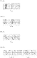
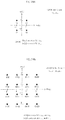
- Figs. 3A to 3D show examples of spreading the components of a 2D-RC and a 4D-RC.
- Figs, 3A, 3B, 3C, and 3D each show an example of mapping two components of a 2D-RC and of mapping four components of a 4D-RC when a FEC block is mapped to one frame, two frames, three frames, and four frames respectively.
- each of the smallest squares corresponds to one component.
- the groups of shaded squares in each figure represent two components of the same 2D-RC and four components of the same 4D-RC.
- mapping the two components of a 2D-RC one each onto frame 1 and frame 3, or onto frame 2 and frame 4 guarantees that the time interval between two components of every 2D-RC is two frames. Therefore, it can easily be seen that the mapping shown by the example, in Fig. 3D is optimal.
- mapping the two components of a 2D-RC one each onto frame 1 and frame 2, or onto frame 3 and frame 4 makes the time interval between the two components of every 2D-RC the same, but the time interval is only one frame. Furthermore, mapping the two components of a 2D-RC one each onto frame 1 and frame 4, or onto frame 2 and frame 3, makes the average time interval between the two components of every 2D-RC two frames, but the time interval between the two components of a 2D-RC is not the same for every 2D-RC (i.e. the time interval is either one frame or three frames). Accordingly, as compared to the mapping shown by the example in Fig. 3D , these are not good mappings.
- a transmitter, a transmission method, a receiver, and a reception method according to Embodiment of the present invention are based on the ⁇ Examination and Discovery by the Inventor>> above, and are described below with reference to the drawings.
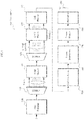
- Fig. 4 is a block diagram showing the structure of a transmitter 100A in Embodiment of the present invention.
- the same reference signs are used and a description is omitted for constituent elements to which applies the description of the constituent elements of the transmitter 100 in Fig. 1 as described in the section ⁇ Examination and Discovery by the Inventor>> above.
- the transmitter 100A in Fig. 4 includes a FEC encoder 110, a demultiplexer 115, a PAM mapper 120, a demultiplexer 125, a constellation rotation unit 130, a cell mapper 140A, a cell interleaver 150A, a frame interleaver 160A, a frame mapper 170A, a modulator 180, and a transmit antenna 190.
- the cell mapper 140A maps D components of each D-dimensional constellation block provided from the constellation rotation unit 130 onto D adjacent (contiguous) complex cells in a complex cell sequence including N C complex cells. Note that the present invention does not particularly limit the details of the mapping processing as long as the D components in each D-dimensional constellation block are mapped in D contiguous complex cells,
- the following describes two different procedures employed by the cell mapper 140A to map the D components of each D-dimensional constellation block onto D contiguous complex cells.
- the cell mapper 140A maps the D components of each D-dimensional constellation block onto a real component and an imaginary component of each of D/2 contiguous complex cells, and inserts a relative delay of D/2 complex cells between the real component and the imaginary component of each of the complex cells.
- the relative delay is cyclical with a specified period.
- the specified period is generally a multiple of D and a divisor of N C .
- the specified period is referred to as a cyclic delay period.
- Figs. 5 and 6 show specific examples of this processing. Note that in each of Figs. 5 and 6 , and Fig 7, 8 , 11, 12 , 13 , 14 , 20, and 21 which are described later, each of the smallest squares corresponds to one component of a 2D-RC or 4D-RC, and each pair of the smallest squares, which are adjacent vertically (the top square being a real component Re and the bottom square being an imaginary component Im), corresponds to one complex cell. In Figs. 5 and 6 , and Figs. 7, 8 . 11, 12 , 13 , 14 , 20, and 21 which are described later, the values in the smallest squares (1, 2,...) are indexes that each indicate a 2D-RC or a 4D-RC.
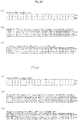
- Fig. 5 shows an example of cell mapping performed by the cell mapper 140A shown in Fig. 4 for two-dimensional rotated constellation blocks (2D-RC).
- the portions (b), (c), (d), and (e) of Fig. 5 show the cases where the cyclic delay periods are 24, 8, 4, and 2, respectively.
- Fig. 6 shows an example of cell mapping performed by the cell mapper 140A shown in Fig. 4 for four-dimensional rotated constellation blocks (4D-RC).
- the portions (b), (c), and (d) of Fig. 6 show the cases where the cyclic delay periods are 24, 8, and 4, respectively. For obvious reasons, a cyclic delay period of 2 is not possible in the case of 4D-RC.
- the cyclic delay period for 2D-RC may be 12 or 6, and the cyclic delay period for 4D-RC may be 12.
- the cell mapper 140A may cyclically delay the real components by D/2 complex cells instead of cyclically delaying the imaginary components by D/2 complex cells as shown in Figs. 5 and 6 .
- the cell mapper 140A maps each pair of D-dimensional constellation blocks onto D contiguous complex cells. This cell mapping is equivalent to the case where the cyclic delay period is D in the aforementioned cell mapping procedure. Specifically, the cell mapper 140A maps D components of one of the pair of constellation blocks onto the real components of D complex cells, and maps D components of the other constellation block onto the imaginary components of D complex cells.
- Figs. 7 and 8 show specific examples of this processing.
- Fig. 7 shows an example of cell mapping performed by the cell mapper 140A shown in Fig. 4 for two-dimensional rotated constellation blocks (2D-RC).
- the cell mapper 140A maps, for each pair of 2D-RC. two components of one of the pair of 2D-RC onto the real components of two contiguous complex cells, and maps two components of the other one of the pair of 2D-RC onto the imaginary components of the same two contiguous complex cells.
- the cell mapper 140A maps two components of the 2D-RC of index 1 onto the real components of two contiguous complex cells, and maps two components of the 2D-RC of index 2 onto the imaginary components of the same two contiguous complex cells.
- Fig. 8 shows an example of cell mapping performed by the cell mapper 140A shown in Fig. 4 for four-dimensional rotated constellation blocks (4D-RC).
- the cell mapper 140A maps, for each pair af 4D-RC, four components of one of the pair of 4D-RC onto the real components of four contiguous complex cells, and maps four components of the other one of the pair of 4D-RC onto the imaginary components of the same four contiguous complex cells. For example, concerning a 4D-RC indicated by index 1 and a 4D-RC indicated by index 2, the cell mapper 140A maps four components of the 4D-RC of index 1 onto the real components of four contiguous complex cells, and maps four components of the 4D-RC of index 2 onto the imaginary components of the same four contiguous complex cells.
- the complex cells of a FEC block resulting from the cell mapping by the cell mapper 140A are provided to the cell interleaver 150A.
- the cell interleaver 150A applies a permutation (cell interleaving) to the complex cells af the FEC block so that D components of each D-dimensional constellation block are evenly spread over the entire FEC block.
- the parameters relating to this permutation are: N C which indicates the number of complex cells per FEC block; and D which indicates the number of dimensions (the number of components) of each constellation block.
- the permutation by the cell interleaver 150A corresponds to the pseudo-random cell permutation in the DVB-T2 standard, although the details of the processing are different from the pseudo-random cell permutation.
- the permutation by the cell interleaver 150A ensures an approximately even spreading of the D components of each D-dimensional constellation block. This improves the performance of the rotated constellation.
- the following describes a preferred permutation performed by the cell interleaver 150A on the complex cells in a FEC block.
- the cell interleaver 150A writes N C complex cells or the FEC block column by column into an interleaver matrix with D rows and ceil(N C /D) columns, in the order in which the N C complex cells are provided from upstream. Then. the cell interleaver 150A reads the complex cells that have been written from the interleave matrix, row by row, and outputs the complex cells to downstream in the order in which the (complex cells are read.
- the function ceil(A) is a function that returns the smallest integer greater than or equal to A.
- N C is not a divisor of D.
- N C is always a multiple of D/2, only D/2 complex cells will be missing in the last column (i.e. half the column).
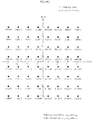
- Figs. 9 and 10 show specific examples of this processing. Note that the values (1, 2, ...) in Figs. 9 and 10 are not indexes indicating the components of constellation blocks, but are indexes indicating the complex cells of a FEC block. The arrows in each of Figs. 9 and 10 indicate a write order and a read order.
- Fig. 9 shows an example of cell interleaving performed by the cell interleaver 150A shown in Fig. 4 for two-dimensional rotated constellation blocks (2D-RC).
- Fig. 10 shows an example of cell interleaving performed by the cell interleaver 150A shown in Fig. 4 for four-dimensional rotated constellation blocks (4D-RC).
- the aforementioned permutation by the cell interleaver 150A shown in Fig. 4 may also be expressed in mathematical terms.
- N C is a multiple of D.
- index i denoting the index of a complex cell input to the cell interleaver 150A
- index j denoting the index of a complex cell output from the cell interleaver 150A.
- i and j are each 0, 1, ..., N C -1.
- the function rem(i. D) is a function that returns the remainder obtained by dividing i by D.
- the function floor(A) is a function that returns the largest integer less than or equal to A.
- the resulting FEC block consists of D contiguous regions, each region containing one component from each constellation block.
- the distance (interval) between the components of each constellation block is N C /D complex cells or N C /D-1 complex cells with no exception, or except for a predetermined number (a value obtained by dividing N C by the cyclic delay period) of constellation blocks. In other words, the spreading is as even as possible.
- the cell mapper 140A and the cell interleaver 150A generate N C complex cells from the N S components in the FEC block in such a manner that. in a complex cell sequence including the N C complex cells, the distance between D components of each constellation block is N C /D complex cells or N C /D-1 complex cells with no exception, or except for the predetermined number (the value obtained by dividing N C by the cyclic delay period) of constellation blocks.
- Figs. 11 and 12 show examples of the results of cell mapping and cell interleaving described above.
- Fig. 11 shows an example of the results of cell mapping and cell interleaving for two-dimensional rotated constellation blocks (2D-RC)
- Fig. 12 shows an example of the results of cell mapping and cell interleaving for four-dimensional rotated constellation blocks (4D-RC).
- the cyclic delay period consists of the maximum number of complex cells, i.e., 24 complex cells.
- each 2D-RC is respectively included in two regions of component indexes 1 and 2.
- four components of each 4D-RC are respectively included in four regions of component indexes 1 to 4.
- the D components are approximately evenly spread over the entire FEC block.
- 4D-RC the minimum distance between the complex cells each having a component of the same constellation block.
- the permutated FEC block is mapped onto one or more frames in sequential order. If the FEC block is spread over N F > 1 frames, the FEC block is first divided into N F contiguous slices, and each slice is mapped onto exactly one of the N F frames. The FEC block is divided into N F slices in such a manner that the difference in size between the N F slices is one complex cell at a maximum, Preferably, the N F slices are of equal size in order to ensure optimum time diversity. This processing is performed by the frame interleaver 160A and the frame mapper 170A.
- Figs. 13 and 14 show examples of the slicing of the FEC block.
- Fig. 13 shows examples of the slicing of the FEC block for two-dimensional rotated constellation blocks (2D-RC).
- the portion (a) of Fig. 13 shows the FEC block permuted by the cell interleaver 150A,
- the portions (b), (c), and (d) of Fig. 13 show the slicing of the FEC block over two. three, and four frames, respectively.
- Fig. 14 shows examples of the slicing of the FEC block for four-dimensional rotated constellation blocks (4D-RC).
- the portion (a) of Fig. 14 shows the FEC block permuted by the cell interleaver 150A.
- the portions (b), (c), and (d) of Fig, 14 show the slicing of the FEC block over two, three, and four frames. respectively.
- each frame When slicing is used (cf. Fig, 2B ), i.e. the data is transmitted in several bursts (or slices) in each frame instead of being distributed over the frame, each frame will be divided into slices of almost equal size. Preferably, the difference in the number of complex cells included in each slice is one at a maximum. The resulting distribution of the D components of each constellation block is still optimal.
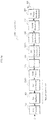
- Fig. 15 is a block diagram showing the structure of the frame interleaver 160A of Fig. 4 .
- the frame interleaver 160A includes a demultiplexer 161A and an interleaver 165A.
- frames 1, 2, 3 are sequentially input to the frame interleaver 160A in the stated order.
- the demultiplexer 161A divides each FEC block into N F blocks, and feeds the N F blocks one by one to N F interleaver branches of the interleaver 165A.
- the demultiplexer 161A divides each FEC block into N F blocks where the difference in the number of complex cells included in each of the N F blocks is one at a maximum.
- the demultiplexer 161 A divides each FEC block into N F blocks of equal size. Note that the N F blocks are referred to as interleaving units (IUs).
- IUs interleaving units
- the interleaver 165A applies a delay, which depends on a branch index, to an input from the demultiplexer 161A.
- the branch delay is equal to a delay in the number of frames corresponding to a zero-based branch index, i.e., 0 frames, frame, or 2 frames in the example of Fig. 15 .
- the interleaver 165A is such that, in order to perform the branch delay, the branch of branch index 0 does not include any memory block.
- the branch of branch index 1 includes one memory block M
- the branch of branch index 2 includes two memory blocks M.
- Each memory block M accommodates the complex cells of the same number of interleaving units as the number of FEC blocks within a frame, i.e., the complex cells of four interleaving units in this example.
- the frame mapper 170A maps the output of the interleaver 165A in the frame interleaver 160A onto frames.
- each FEC block is spread over three adjacent frames.
- Fig. 16 shows an example where four FEC blocks in frame are spread over three frames.
- the interleaved data for each frame may be further divided into several slices.
- the effect is that each interleaving unit is divided into many slices. Accordingly, each FEC block is divided first into interleaving units and then into slices.
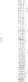
- Fig. 17 shows an example for 24 complex cells per FEC block, interleaving over four frames, and two slices per frame.
- Fig. 18 is a block diagram showing the structure of a receiver 300 according to Embodiment I of the present invention.
- the receiver 300 in Fig. 18 corresponds to the transmitter 100A in Fig. 4 , and mirrors the functionality of the transmitter 100A.
- the receiver 300 includes a receive antenna 310.
- a demodulator 320 a frame demapper 330, a frame deinterleaver 340, a cell deinterleaver 350, a cell demapper 360, a constellation demapper 370, and a forward error correction (FEC) decoder 380.
- FEC forward error correction
- the demodulator 320 receives a baseband signal from a radio-frequency (RF) frontend.
- the RF frontend typically includes the receive antenna 310, a tuner (not shown) for tuning into a desired channel. and a down-converter (not shown) for converting an analog RF signal into a digital baseband signal.
- the demodulator 320 demodulates the digital baseband signal received from the RF frontend. In other words, the demodulator 320 calculates channel fading coefficients based on the digital baseband signal and calculates complex symbols (complex cells) based on the calculated channel fading coefficients. Then, the demodulator 320 outputs a stream of complex cells to the frame demapper 330.
- the frame demapper 330 has a function corresponding to the frame mapping performed by the frame mapper 170A in the transmitter 100A, and extracts, from the frame (cell stream), complex cells belonging, to a desired service or program according to a schedule notified by the transmitter.
- the frame deinterleaver 340 deinterleaves (frame deinterleaving) the extracted complex cells so as to return the complex cells to the order before interleaving by the frame interleaver 160A of the transmitter 100A.
- the output of the frame dcinterleaver 340 consists of a plurality of FEC blocks per frame.
- the cell deinterleaver 350 deinterleaves (cell deinterleaving) N C complex cells of each FEC block so as to return the N C complex cells to the order before interleaving by the cell interleaver 150A of the transmitter 100A.
- the cell demapper 360 extracts D real symbols in each D-dimensional constellation block mapped onto the complex cells of a FEC block. This extraction is performed based on the mapping positions of the D real symbols mapped onto complex cells by the cell mapper 140A of the transmitter 100A.
- the constellation demapper 370 demodulates the D-dimensional constellation blocks. For example. the constellation demapper 370 jointly demodulates the D real symbols of each D-dimensional constellation block, and produces D ⁇ B "soft" bits for each D-dimensional constellation block. Note that in one processing step, the constellation demapper 370 performs derotation corresponding to the rotation by the constellation rotation unit 130 of the transmitter 100A and demapping corresponding to the mapping by the PAM mapper 120 of the transmitter 100A.
- the FEC decoder 380 decodes the soft bits of each FEC block in accordance with the FEC code used by the FEC encoder 110 of the transmitter 100A and provides the results of decoding to subsequent processing blocks for further processing.
- the DVB-T2 Digital Video Broadcasting-Second Generation Terrestrial
- DVB-T2 Digital Video Broadcasting-Second Generation Terrestrial
- DVB-T2 Digital Video Broadcasting-Second Generation Terrestrial
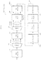
- Fig, 19 is a block diagram showing the structure of a transmitter 500 that employs rotated quadrature amplitude modulation (QAM) constellations according to the DVB-T2 standard.
- QAM quadrature amplitude modulation
- the transmitter 500 includes a FEC encoder 510, a bit interleaver 520, a QAM mapper 530, a constellation rotation unit 540, an RC component separation unit 550 (including a Q-delay insertion unit 551 and a cell interleaver 555), a time/frequency interleaver 560, an OFDM modulator 570, an RF power amplifier 580, and a transmit antenna 590.
- the transmitter 500 receives, as input, binary blocks of a predetermined length, which contain the information to be transmitted.
- the FEC encoder 510 encodes each information block using a FEC code.
- a FEC code According to the DVB-T2 standard, a low-density parity-check (LDPC) code is used as the FEC code.
- LDPC low-density parity-check
- the bit interleaver 520 interleaves the bits of a FEC codeword (FEC block) yielded by the encoding processing (bit interleaving), and provides the bit-interleaved FEC block to the QAM mapper 530. This improves the robustness of the system.
- the QAM mapper 530 maps the bit-interleaved FEC block onto complex QAM symbols a predetermined number of bits at a time.
- a set of B bits modulates the real component of a complex QAM symbol and another set of B bits modulates the imaginary component of the complex QAM symbol.
- Each of the real and imaginary components of the complex QAM symbols is therefore independent and can be regarded as a real-valued pulse amplitude modulation (PAM) symbol (the same PAM symbol as the PAM symbol produced by the PAM mapper 120 shown in Figs. 1 and 4 ).
- PAM pulse amplitude modulation
- the constellation rotation unit 540 rotates the complex QAM symbols produced by the QAM mapper 530 in order to introduce a dependence between the two real-valued PAM symbols that constitute each of the complex QAM symbols. This increases the robustness in fading channels.
- This rotation processing is also referred to as the processing of jointly encoding the two real-valued PAM symbols.
- the rotated complex QAM symbols are regarded as indicators indicating unique points in a two-dimensional space.
- the resulting (2 B ) 2 combinations form a two-dimensional constellation.
- the rotation by the constellation rotation unit 540 is performed by multiplying a vector, which has two real-valued PAM symbols as vector elements, by a 2 ⁇ 2 orthogonal matrix.
- the constellation rotation unit 540 performs joint encoding by multiplying a D-dimensional vector, which has D real-valued PAM symbols as elements, by a D ⁇ D orthogonal matrix.
- N S real symbols (components) of each FEC block are provided from the constellation rotation unit 540 to the RC component separation unit 550.
- the D real symbols of each D-dimensional rotated constellation block be spread as much as possible in time and frequency. In this way, the channel fading that the D real symbols experience becomes as uncorrelated as possible.
- the Q-delay insertion unit 551 of the RC component separation unit 550 first maps the D real symbols of each D-dimensional constellation block onto D/2 complex cells, and thereby maps the real symbols of a FEC block onto N C complex cells. Next, the Q-delay insertion unit 551 cyclically delays the imaginary (or quadrature, hence the name Q-delay) components by D/2 complex cells, and outputs the resulting complex cells to the cell interleaver 555.
- Figs. 20 and 21 show specific examples of this processing, In Figs. 20 and 21 , it is assumed that each FEC block includes 24 complex cells.
- Fig. 20 shows examples of the processing performed by the Q-delay insertion unit 551 shown in Fig. 19 for two-dimensional rotated constellation blocks (2D-RC).
- the portion (a) of Fig. 20 shows the state before the real symbols (components) of 2D-RC are mapped to the complex cells.
- Fig. 21 shows examples of the processing performed by the Q-delay insertion unit 551 shown in Fig. 19 for four-dimensional rotated constellation blocks (4D-RC).
- the portion (a) of Fig. 21 shows the state before the components of 4D-RC are mapped to the complex cells.
- the cell interleaver 555 in the RC component separation unit 550 permutes (shuffles) the N C complex cells obtained as a result of the Q-delay.
- the cell permutation applied by the cell interleaver 555 is a pseudo-random permutation generated using a linear feedback shift register (LFSR).
- LFSR linear feedback shift register
- the cell permutation applied by the cell interleaver 555 is different for each FEC block.
- the time/frequency interleaver 560 performs time interleaving and frequency interleaving to spread the complex cells of each FEC block in time and frequency.
- the time interleaving and the frequency interleaving are performed by two different blocks.
- the OFDM modulator 570 uses orthogonal frequency-division multiplexing (OFDM) modulation.
- An up-converter (not shown) converts a digital baseband signal into an analog radio-frequency (RF) signal.
- the RF power amplifier 580 amplifies the power of the analog RF signal.
- the analog RF signal whose power has been amplified is then transmitted from the transmit antenna 590.
- bit interleaver 520 shown in Fig. 19 , with reference to Figs. 22 and 23 .
- Fig. 22 is a block diagram showing the structure of the bit interleaver 520 of Fig. 19 .
- the bit interleaver 520 according to the DVB-T2 standard includes a parity interleaver 522, a column-row interleaver 524. and a bit-to-cell demultiplexer 526.
- the parity interleaver 522 interleaves the parity bits of the systematic LDPC codeword obtained as a result of the encoding processing by the FEC encoder 510.
- the column-row interleaver 524 interleaves the bits of systematic LDPC codeword whose parity bits have been interleaved by the parity interleaver 522.
- bit-to-cell demultiplexer 526 demultiplexes the bits of the systematic LDPC codeword which have been interleaved by the column-row interleaver 524 to cell words prior to the mapping to a QAM constellation.
- the demultiplexing includes processing equivalent to the permutation of the columns of an interleaver matrix of the column-row interleaver 524.
- the column-row interleaver 524 and the associated bit-to-cell demultiplexer 526 are used only for higher-order constellations, such as 16-QAM constellations. 64-QAM constellations, and 256-QAM constellations. For QPSK (4-QAM) constellations, only the parity interleaver 522 is used.
- Fig. 23 a write order in which to write data bits to an interleaver matrix and a read order in which to read the data bits from the interleaver matrix are indicated by dotted lines.
- the column-row interleaver 524 serially writes the data bits received from the parity interleaver 522 (the bits of a FEC codeword whose parity bits have been interleaved) column by column into an interleaver matrix, while twisting the write start position of each column by a specified number of bits. Also, the column-row interleaver 524 serially reads the data bits written in the interleaver matrix row by row.
- the first bit (the most significant bit (MSB) of a baseband header) of the FEC codeword (FEC frame) is written first in the interleaver matrix and read first from the interleave matrix. Note that the "LSB of FECFRAME" in Fig. 23 indicates the least significant bit (LSB) of the FEC codeword (FEC frame) after the column-row interleaving,
- the number of columns in the column-row interleaver is equal to the number of bits encoded onto a complex QAM symbol, i.e., 2 ⁇ B, or to twice this number (1 ⁇ 2 ⁇ B).
- Each cell word includes the same number of bits as the bits encoded onto one complex QAM symbol. i.e.. 2 ⁇ B bits.
- the number of bits of each cell word is two for a QPSK (4-QAM) symbol. four for a 16-QAM symbol, six for a 64-QAM symbol, and eight for a 256-QAM symbol.
- Each cell word is modulated by the QAM mapper 530 with use of a particular mapping constellation, such as QPSK (4-QAM), 16-QAM, 64-QAM or 256-QAM.
- the constellations and the details of Gray mapping applied to the bits according to the DVB-T2 standard are illustrated in Figs. 24A, 24B , and 24C for QPSK (4-QAM). 16-QAM. and 64-QAM, respectively,
- the inventor has realized that the cell interlcaver 555 in the DVB-T2 standard includes two distinct functions.
- first function is to spread the burst errors that occur in the channel as irregularly as possible throughout a FEC block. This function is performed very well by the pseudo-random permutation by the cell interleaver 555 in the DVB-T2 standard, and is applicable to both rotated and non-rotated constellations.
- the other one of the functions (hereinafter "second function"), which is achieved in conjunction with the time/frequency interleaver, is to spread the rotated constellation components over time and frequency.
- This function is of course relevant only for rotated constellations.
- the pseudo-random permutation by the cell interleaver 555 as used in the DVB-T2 standard achieves a sub-optimal separation of the D real symbols of each D-dimensional rotated constellation block in time and frequency. This results in sub-optimal performance in fading or erasure channels.
- the separation of the D real symbols of each D-dimensional rotated constellation block can be achieved by replacing the cell interleaver 555 that applies the pseudo-random permutation according to the DVB-T2 standard with an interleaver that is specifically optimized for separating the D real symbols as far as possible in time and frequency.
- interleaves have regular structures, which make them sub-optimal with respect to the first function.
- a transmitter, a transmission method, a receiver, and a reception method according to Embodiment 2 of the present invention are based on the ⁇ Further Examination and Further Discovery by the Inventor>> above, and are described below with reference to the drawings.
- Fig. 25 is a block diagram showing the structure of a transmitter 500A according to Embodiment 2 of the present invention.
- the same reference signs are used and a description is omitted for constituent elements to which applies the description of the constituent elements of the transmitter 500 in Fig. 19 as described in the section ⁇ Further Examination and Further Discovery by the Inventor>> above.
- the transmitter 500A is basically the same as the transmitter 500 except that a cell interleaver 535A is arranged between the QAM mapper 530 and the constellation rotation unit 540, and that the RC component separation unit 550 is replaced with an RC component separation unit 550A which differs from the RC component separation unit 550 in terms of processing.
- the cell interleaver 535A achieves the first function of spreading the burst errors that occur in the channel as irregularly as possible throughout a FEC block.
- the cell interleaver 535A permutes complex QAM symbols (i.e.. groups of two real-valued PAM symbols) output from the QAM mapper 530. which are complex QAM symbols prior to being subjected to the rotation processing by the constellation rotation unit 540.
- a pseudo-random permutation is suitable as the permutation by the cell interleaver 535A to realize the first function.
- a pseudo-random interleaver such as the cell interleaver 555 according to the DVB-T2 standard is suitable as the cell interleaver 535A.
- a cell interleaver 535B may be arranged upstream of the QAM mapper 530, instead of the cell interleaver 535A arranged downstream of the QAM mapper 530.
- the cell interleaver 535B of a transmitter 500B. which is shown in Fig. 26 , interleaves groups of 2 ⁇ B bits instead of interleaving QAM symbols. Each group modulates one QAM symbol. Note that a combination of the bit interleaver 520 and the cell interleaver 535B may be regarded as a new bit interleaver.
- the RC component separation unit 550A is arranged downstream of the constellation rotation unit 540, and achieves the second function of spreading the components of rotated constellation blocks.
- the RC component separation unit 550A performs the same processing performed by the cell mapper 140A and the cell interleaver 150A in the transmitter 100A according to Embodiment I.
- a detailed description of the RC component separation unit 550A is omitted here, since the description of the cell mapper 140A and the cell interleaver 150A of Embodiment 1 is applicable as the description of the RC component separation unit 550A.
- a FEC block permutated by the RC component separation unit 550A is mapped onto one or more frames in sequential order, and/or onto one or more channels or frequencies. This step is performed by the time/frequency interleaver 560. If the FEC block is spread over N F > 1 frames, the FEC block is first divided into N F contiguous slices, and each slice is mapped onto exactly one of the N F frames. The FEC block is divided into N F slices in such a manner that the difference in size between the N F slices is one complex cell at a maximum. Preferably, the N F slices are of equal size in order to ensure optimum time diversity.
- Fig. 27 is a block diagram showing the structure of a receiver 700 according to Embodiment 2 of the present invention.
- the receiver 700 shown in Fig. 27 corresponds to the transmitter 500A shown in Fig. 25 or the transmitter 500B shown in Fig. 26 , and mirrors the functionality of the transmitter 500A or the transmitter 500B.
- the receiver 700 includes a receive antenna 710, a radio-frequency (RF) frontend 720, an OFDM demodulator 730, a time/frequency deinterleaver 740, an RC component combining unit 750, a constellation demapper 760, a cell deinterleaver 770, a bit deinterleaver 780, and a FEC decoder 790.
- RF radio-frequency
- a combination of the cell deinterleaver 770 and the bit deinterleaver 780 may be regarded as a new bit deinterleaver.
- the RF frontend 720 typically includes a tuner (not shown) for tuning into a desired channel, and a down-converter (not shown) for converting an analog RF signal into a digital baseband signal.
- the OFDM demodulator 730 demodulates a digital baseband signal. In other words, the OFDM demodulator 730 calculates channel fading coefficients based on the digital baseband signal and calculates complex symbols (complex cells) based on the calculated channel fading coefficients. Then, the OFDM demodulator 730 outputs a stream of complex cells to the time/frequency deinterleaver 740.
- the time/frequency deinterleaver 740 extracts, from the frame (stream), complex cells belonging to a desired service or program according to a schedule notified by the transmitter.
- the time/frequency deinterleaver 740 deinterleaves (time/frame deinterleaving) the extracted complex cells so as to return the complex cells to the order before interleaving by the time/frequency interleaver 560 of the transmitter 500A or the transmitter 500B.
- the time/frequency deinterleaver 740 outputs a plurality of FEC blocks each consisting of a plurality of complex cells.
- the RC component combining unit 750 extracts D real symbols of each of N S /D D-dimensional constellation blocks that have been separated by the RC component separation unit 550A of the transmitter 500A or the transmitter 500B. Here, the extraction is based on the processing of the RC component separation unit 550A of the transmitter 500A or the transmitter 500B. The, the RC component combining unit 750 combines the D real symbols thus extracted into D/2 contiguous complex cells.
- the constellation demapper 760 sequentially demodulates the N S /D D-dimensional constellation blocks. For example, the constellation demapper 760 jointly demodulates the D real symbols of each D-dimensional constellation block, and produces D ⁇ B "soft" bits for each D-dimensional constellation block. Note that in one processing step, the constellation demapper 760 performs derotation corresponding to the rotation by the constellation rotation unit 540 of the transmitter 500A or the transmitter 500B and demapping corresponding to the mapping by the QAM mapper 530.
- the cell deinterleaver 770 deinterleaves groups of 2 ⁇ B "soft" bits output from the constellation demapper 760 (cell deinterleaving).
- the bit deinterleaver 780 deinterleaves the groups of bits output from the cell deinterleaver 770 so as to return the groups of bits to the order before interleaving by the bit interleaver 520 of the transmitter 500A or the transmitter 500B (bit deinterleaving),
- the FEC decoder 790 decodes the soft bits of each FEC block in accordance with the FEC code used by the FEC encoder 510 of the transmitter 500A or the transmitter 500B, and provides the results of decoding to subsequent processing blocks for further processing.
- the present invention is not limited to the above-described embodiments, but rather may be embodied in a variety of ways, such as those described below, for achieving the aim of the present invention or other aims related or associated thereto. For example, the following modifications are possible.
- the first, second, and third transmission methods and the first, second, and third transmission transmitters can spread D real symbols of a D-dimensional rotated constellation block so as to be even and to have a large minimum distance, thereby achieving excellent time diversity.
- a fourth transmission method is any of the first, second, and third transmission methods, wherein the complex symbol sequence is divided into N F slices, and the N S /2 complex symbols are mapped onto N F frames, so that all the complex symbols of each of the N F slices are mapped onto the same frame.
- a fifth transmission method is the fourth transmission method, wherein the division of the complex symbol sequence is performed in a manner that a difference in the number of complex symbols included in each of the N F slices is one at a maximum.
- the fourth and fifth transmission methods further improve time diversity.
- a sixth transmission method is any of the first, second, and third transmission methods, further comprising interleaving groups that are each made up of two of the real-valued symbols in the real-valued symbol sequence, the interleaving being performed between the generation of the real-valued symbols sequence and the conversion of the D-dimensional vectors.
- a fourth transmitter is any of the first, second, and third transmitters, further comprising an interleaver interleaving groups that are each made up of two of the real-valued symbols in the real-valued symbol sequence, the interleaver being provided between the real-valued symbol sequence generator and the converter.
- the sixth transmission method and the fourth transmitter can spread the burst errors that occur in the channel, thereby improving robustness against the burst errors that occur in the channel.
- a seventh transmission method is any of the first, second, and third transmission methods, wherein each of the real-valued symbols is obtained as a result of mapping of B bits, and the seventh transmission method further comprises interleaving groups of 2 ⁇ B bits in a bit sequence including a plurality of bits of the encoded block of data, the interleaving being performed between the encoding of the block of data and the generation of the real-valued symbol sequence.
- a fifth transmitter is any of the first, second, and third transmitters, wherein each of the real-valued symbols is obtained as a result of mapping of B bits, and the fifth transmitter further comprises an interleaver interleaving groups of 2 ⁇ B bits in a bit sequence including a plurality of bits of the encoded block of data, the interleaver being provided between the encoder and the real-valued symbol sequence generator.
- the seventh transmission method and the fifth transmitter can spread the burst errors that occur in the channel, thereby improving robustness against the burst errors that occur in the channel.
- a first reception method is for receiving digital data comprising: receiving a complex symbol sequence including N C complex symbols obtained through any of the first, second, and third transmission methods; extracting, for each of ⁇ N S /D D-dimensional rotated vectors. D real symbols of the D-dimensional rotated vector from the complex symbols sequence; generating an encoded block of data by sequentially demapping the N S /D D-diniensional rotated vectors; and decoding the encoded block of data by an error correction code.
- a first receiver is for receiving digital data comprising; a receiving unit receiving a complex symbol sequence including N C complex symbols obtained by the transmitter of any of the first, second, and third transmitters; a real-valued symbol extractor extracting, for each of N S /D D-dimensional rotated vectors, D real symbols of the D-dimensional rotated vector from the complex symbol sequence; a demapper generating an encoded block of data by sequentially demapping the N S /D D-dimensional rotated vectors; and a decoder decoding the encoded block of data by an error correction code.
- the first reception method and the first receiver can spread D real symbols of D-dimensional rotated constellation block so as to be even and to have a large minium distance, thereby achieving excellent time diversity.
- a second reception method is for receiving digital data comprising: receiving a complex symbol sequence including N C complex symbols obtained through either of the sixth and seventh transmission methods; extracting, for each of N S /D D-dimensional rotated vectors, D real symbols of the D-dimensional rotated vector from the complex symbol sequence; generating an encoded block of data by sequentially demapping the N S /D D-dimensional rotated vectors; deinterleaving a plurality of bits of the encoded block of data based on the interleaving of the groups; and decoding the encoded block of data that has been deinterleaved, with use of an error correction code.
- a second receiver is for receiving digital data comprising: a receiving unit receiving a complex symbol sequence including N C complex symbols obtained by either of the fourth and fifth transmitters; a real-valued symbol extractor extracting, for each of N S /D D-dimensional rotated vectors, D real symbols of the D-dimensional rotated vector from the complex symbol sequence; a demapper generating an encoded block of data by sequentially demapping the N S /D D-dimensional rotated vectors; a deinterleaver deinterleaving a plurality of bits of the encoded block of data based on the interleaving of the groups by the interleaver; and a decoder decoding the encoded block of data that has been deinterleaved, with use of an error correction code.
- the second reception method and the second receiver can spread D real symbols of a D-dimensional rotated constellation block so as to be even and to have a large minimum distance, thereby achieving excellent time diversity and improving robustness against the burst errors that occur in the channel.
- the transmission method may include the complex symbol sequence being divided into N F slices, and the N S /2 complex symbols being mapped into N F frames, so that all the complex symbols of each of the N F slices are mapped onto the same frame.
- the transmission method can also include that
- the transmission method may further comprise
- reception methods for receiving digital data comprises
- One application is a
- Another application is a
- the transmitter further comprises
- a further application is a
- Another application is a
- the present invention is applicable to communications using rotated constellations.
Landscapes
- Engineering & Computer Science (AREA)
- Computer Networks & Wireless Communication (AREA)
- Signal Processing (AREA)
- Error Detection And Correction (AREA)
- Digital Transmission Methods That Use Modulated Carrier Waves (AREA)
Abstract
Description
- The present invention relates to the field of digital communications, and more specifically to the technology for transmission and reception employing multi-dimensional rotated constellations.
- In recent years, there have been transmitters that use multi-dimensional rotated constellations (e.g., rotated quadrature amplitude modulation (QAM) constellations) (see
Patent Literature 1 and Non-PatentLiterature 1, for example). - Such a transmitter has a function of multiplying each of vectors by an orthogonal matrix (rotating each of vectors), each of the vectors having, as elements thereof, a predetermined number of real-valued pulse amplitude modulation (PAM) symbols output from a symbol mapper. In such a transmitter, the predetermined number of elements of each vector resulting from the rotation process (i.e., each rotated vector) are spread along the time axis.
- [Patent Literature 1]
European Patent Application Publication No.2288048 - [Non-Patent Literature 1]
ETSI EN 302 755 V1.1.1 (DVB-T2 Standard) - 'time diversity relies on the spreading of the predetermined number of elements of each rotated vector along the time axis.
- Accordingly, an object of the present invention is to provide a transmission method that achieves excellent time diversity by appropriately spreading the predetermined number of elements of each rotated vector along the time axis.
- To achieve the above-described object, the present invention provides a transmission method for transmitting digital data, comprising: encoding a block of data of a predetermined length with an error correction code; generating a real-valued symbol sequence including NS real-valued symbols by mapping the encoded block of data onto real-valued symbols a predetermined number of bits at a time; converting D-dimensional vectors into D-dimensional rotated vectors by multiplying each of the D-dimensional vectors by a D×D orthogonal matrix, each of the D-dimensional vectors having D of the real-valued symbols in the real-valued symbol sequence as elements, each of the D-dimensional rotated vectors having D real symbols as elements; and generating a complex symbol sequence from NS real symbols resulting from the conversion, the complex symbol sequence including NC = NS/2 complex symbols, wherein the complex symbol sequence is generated such that a distance between any two of the D real symbols of each of the D-dimensional rotated vectors is NC/D complex symbols or NC/D-1 complex symbols, or such that the distance between any two of the D real symbols of each of the D-dimensional rotated vectors, except for part of the D-dimensional rotated vectors, is NC/D complex symbols or NC/D-1 complex symbols.
- The transmission method described above achieves excellent time diversity.
-
-
Fig. 1 is a block diagram showing the structure of atransmitter 100 that employs generalized rotated constellations. -
Fig. 2A shows an example of combining frame interleaving and frame mapping. -
Fig. 2B shows another example of combining frame interleaving and frame mapping. -
Fig. 2C shows another example of combining frame interleaving and frame mapping. -
Fig. 2D shows another example of combining frame interleaving and frame mapping. -
Fig. 2E shows another example of combining frame interleaving and frame mapping. -
Fig. 3A schematically shows an example of spreading a FEC block over one frame according to an embodiment of the present invention. -
Fig. 3B schematically shows an example of spreading a FEC block over two frames according to an embodiment of the present invention. -
Fig. 3C schematically shows an example of spreading a FEC block over three frames according to an embodiment of the present invention. -
Fig. 3D schematically shows an example of spreading a FEC block over four frames according to an embodiment of the present invention. -
Fig. 4 is a block diagram showing the structure of atransmitter 100A that employs rotated constellations according toEmbodiment 1 of the present invention. -
Fig. 5 shows an example of cell mapping performed by acell mapper 140A shown inFig. 4 for two-dimensional rotated constellation blocks. -
Fig. 6 shows an example of cell mapping performed by thecell mapper 140A shown inFig. 4 for four-dimensional rotated constellation blocks. -
Fig. 7 shows another example of cell mapping performed by thecell mapper 140A shown inFig. 4 for two-dimensional rotated constellation blocks. -
Fig. 8 shows another example of cell mapping performed by thecell mapper 140A shown inFig. 4 for four-dimensional rotated constellation blocks. -
Fig. 9 shows an example of cell interleaving performed by acell interleaver 150A shown inFig. 4 for two-dimensional rotated constellation blocks. -
Fig. 10 shows an example of cell interleaving performed by thecell interleaver 150A shown inFig. 4 for four-dimensional rotated constellation blocks. -
Fig. 11 shows an example of a result of cell mapping and cell interleaving for two-dimensional rotated constellation blocks. -
Fig. 12 shows an example of a result of cell mapping and cell interleaving for four-dimensional rotated constellation blocks. -
Fig. 13 shows an example of slicing a FEC block for two-dimensional rotated constellation blocks. -
Fig. 14 shows an example of slicing a FEC block for four-dimensional rotated constellation blocks. -
Fig. 15 is a block diagram showing the structure of aframe interleaver 160A shown inFig. 4 . -
Fig. 16 schematically shows an example of spreading a FEC block over a plurality of frames, which is performed by aframe interleaver 160A shown inFig. 15 . -
Fig. 17 shows an example of splitting a FEC block into interleaving units and further splitting the interleaving units into slices. -
Fig. 18 is a block diagram showing the structure of areceiver 300 that employs rotated constellations according to Embodiment I of the present invention. -
Fig. 19 is a block diagram showing the structure of atransmitter 500 that employs rotated quadrature amplitude modulation (QAM) constellations according to the DVB-T2 standard. -
Fig. 20 shows an example of processing performed by a Q-delay insertion unit 551 shown inFig. 19 for two-dimensional rotated constellation blocks. -
Fig. 21 shows an example of processing performed by the Q-delay insertion unit 551 shown inFig. 19 for four-dimensional rotated constellation blocks. -
Fig. 22 is a block diagram showing the structure of abit interleaver 520 shown inFig. 19 . -
Fig. 23 shows the outline of an operation by a column-row interleaver 524 shown inFig. 22 . -
Fig. 24A shows bit mapping for a QPSK constellation. -
Fig. 24B shows bit mapping for 16-QAM constellation. -
Fig. 24C shows bit mapping for a 64-QAM constellation. -
Fig. 25 is a block diagram showing the structure of atransmitter 500A that employs rotated constellations according toEmbodiment 2 of the present invention. -
Fig. 26 is a block diagram showing the structure of atransmitter 500B that employs rotated constellations according toEmbodiment 2 of the present invention. -
Fig. 27 is a block diagram showing the structure of areceiver 700 that employs rotated constellations according toEmbodiment 2 of the present invention. - First, description is provided on a transmission technology that employs generalized multi-dimensiona) rotated constellations (e.g.. rotated quadrature amplitude modulation (QAM) constellations), with reference to the drawings.
-
Fig. 1 is a block diagram showing the structure of a transmitter that employs generalized multi-dimensional rotated constellations. - A
transmitter 100 includes a forward-error-correction (FEC)encoder 110, ademultiplexer 115, aPAM mapper 120, ademultiplexer 125, aconstellation rotation unit 130, acell mapper 140, acell interleayer 150, aframe interleaver 160, aframe mapper 170, amodulator 180, and a transmitantenna 190. - The
transmitter 100 receives, as input, binary blocks of a predetermined length, which contain the information to be transmitted. - The
FEC encoder 110 encodes each information block using a forward-error-correction (FEC) code. This yields a FEC codeword. The encoding processing includes calculation of redundancy bits and addition of the redundancy bits to the information block in order to make decoding of the information block by the receiver more robust against errors. Two notable examples of FEC code families are a low-density parity-check (LDPC) code and a turbo code. The present invention, however, does not particularly limit the type of FEC code used by theFEC encoder 110. The most important parameter in a FEC code is a code rate. The code rate is a ratio between the number of information bits and the number of codeword bits (code rate = number of information bits/number of codeword bits). Note that the present invention does not particularly limit the code rate. - The FEC codeword yielded by the encoding processing is provided to the
demultiplexer 115. Hereinafter, a FEC codeword is referred to as a FEC block. Thedemultiplexer 115 demultiplexes the bits of the FEC block into groups or B bits, and provides the groups of B bits to thePAM mapper 120. ThePAM mapper 120 maps the groups of B bits onto real-valued pulse amplitude modulation (PAM) symbols. Each PAM symbol takes a value from a discrete set of 2B values. How the B bits are mapped onto PAM symbols is well understood and not directly relevant to the present invention. The relevant aspect is that each FEC block is transformed into a block of PAM symbols. In the following, the number of RAM symbol per FEC block will be denoted by NS. - Prior to being mapped to PAM symbols, the FEC block may undergo additional processing steps, such as bit permutation or puncturing. These aspects are well known in the art.
- The NS real-valued PAM symbols produced by the
PAM mapper 120 are then provided to thedemultiplexer 125. Thedemultiplexer 125 demultiplexes the NS real-valued PAM symbols into D-dimensional vectors that each have D real-valued PAM symbols as elements. These vectors can be regarded as identifying unique points in a D-dimensional space. The resulting (2B)D combinations form a D-dimensional constellation. - Each D-dimensional vector is provided from the
demultiplexer 125 to theconstellation rotation unit 130. Theconstellation rotation unit 130 multiplies each D-dimensional vector by a D-by-D orthogonal matrix (hereinafter "DxD orthogonal matrix"). Here, letting the D-dimensional vector provided to theconstellation rotation unit 130 be V, the orthogonal matrix used for matrix multiplication be R, and the D-dimensional rotated vector resulting from matrix multiplication be V', then V' = RV. The multiplication of the orthogonal matrix can be regarded as a generalized vector rotation in the D-dimensional space, hence the term "rotated constellations". As the present invention does not limit the orthogonal matrix (also referred to as "rotation matrix") used by theconstellation rotation unit 130 to an orthogonal matrix with a particular structure, any orthogonal matrix may be used. Use of rotated constellations is a well-known technique in this technical field, and therefore a detailed explanation thereof is omitted. Precise details can be found in Patent Literature 1 (EP 2288048 ), which is incorporated herewith in its entirety. - Preferably, D is a power of 2, such as 2, 4, or 8. Typically NS is a multiple of D. If this is not the case, the last 1 to D-1 PAM symbols in the FEC block can be left unchanged, i.e. non-rotated. This affects none of the aspects of the present invention.
- It is also preferred that NS is a multiple of 2.
- In the following, the D-dimensional rotated vectors obtained by rotating vectors that each have D real-valued PAM symbols as elements are referred to as D-dimensional rotated constellation blocks or simply D-dimensional constellation blocks. The real symbols constituting a D-dimensional constellation block are referred to as components or dimensions.
- Note that two-dimensional rotated constellation blocks are referred to as 2D rotated constellation blocks or as 2D-RC. Similarly, four-dimensional rotated constellation blocks are referred to as 4D rotated constellation blocks or as 4D-RC.
- After the multiplication of the orthogonal matrix (after the rotation process), the NS real symbols (components) of each FEC block are provided from the
constellation rotation unit 130 to thecell mapper 140. Thecell mapper 140 maps the NS real symbols onto NC =NS/2 complex symbols (cell mapping). The complex symbols are also referred to as complex cells or simply cells. - The cell interleaver 150 receives the complex cells from the
cell mapper 140, and interleaves the complex cells (cell interleaving). - In order to increase the time diversity of the system, the
frame interleaver 160 performs interleaving so as to spread the NC complex cells of each FEC block along the time axis (frame interleaving). Theframe mapper 170 maps the complex cells spread along the time axis onto a frame (frame mapping). - The frame interleaver 160 may be a block interleaver, a convolutional interleaver, or a combination of both. In the DVB-T2 standard for example, the
frame interleaver 160 is a block interleaver and is referred to as a time interleaver. - The time diversity of the system increases with the interleaving duration, which should be maximized. Very long interleaving durations, however, lead to high latency, slow initial acquisition (e.g. for TV channel zapping), and high memory requirements in both the transmitter and the receiver.
- Typically, the transmitted signal is organized in one or more frames of identical duration. The NC complex cells of each FEC block can be transmitted in one or more frames N1. Preferably, the number of complex cells in each frame is the same. Within a frame, the complex cells can be transmitted in a single burst or interleaved with other complex cells over a longer duration. Spreading the complex cells over the entire frame provides the best diversity and robustness. In the present invention, however, the mechanism for frame interleaving and frame mapping is not limited to a particular mechanism.
- After being subjected to frame, interleaving and frame mapping, the complex cells are further processed by a processing block including at least the
modulator 180, an up-converter (not shown), and a radio-frequency (RF) power amplifier (not shown). Themodulator 180 uses, for example, orthogonal frequency-division multiplexing (OFDM) modulation. Also, themodulator 180 may include a function of frequency interleaving for increased frequency diversity. The up-converter converts a digital baseband signal into an analog radio-frequency (RF) signal. The RF power amplifier amplifies the power of the analog RH signal. The analog RF signal whose power has been amplified is then transmitted from the transmitantenna 190. -
Figs. 2A to 2E show example of possible combinations of frame interleaving and frame mapping. InFigs. 2A to 2E , as well as in later-describedFigs. 3A to 3D , the horizontal (lateral) axis and the vertical (longitudinal) axis represent time and frequency, respectively. -
Fig. 2A shows the case when a FEC block is transmitted in a small portion of a frame. The resulting time diversity is low. If the region of the frame in which the FEC block is transmitted is affected by, for example, impulsive noise, all the complex cells of the FEC block will be affected by the impulsive noise and the FEC block may no longer be decodable. -
Fig. 2B shows the case when a FEC block is transmitted as two bursts over a frame. In the case ofFig. 2B , the time diversity increases as compared to the case shown inFig. 2A . Hereinafter, the bursts are also referred to as slices. -
Fig. 2C shows the case when a FEC block is spread over an entire frame and transmitted. In the case ofFig. 2C , the time diversity increases significantly as compared to the cases shown inFigs. 2A and 2B . If an impulsive noise destroys, for example, the beginning of the frame, only a part of the complex cells in the FEC block will be affected by the impulsive noise (the remaining part of the complex cells will not be affected). As a result, the probability of decoding failure is reduced. -
Fig. 2D shown the case when each FEC block is interleaved and spread over two adjacent frames and transmitted. In the case ofFig. 2D , the time diversity increases as compared to the cases shown inFigs. 2A. 2B, and 2C . However, the required memory for interleaving and deinterleaving doubles in size. -
Fig. 2E shows the case when each FEC block is interleaved and spread over two non-adjacent frames with a gap of one frame in between and transmitted. In each of the two frames, the complex cells are transmitted as short bursts. This is known as time slicing and allows the receiver to save power consumption between bursts. The interleaving period is four frames, which further increases the amount of memory required for interleaving and deinterleaving, as compared to the case shown inFig. 2C . - Generally, the time diversity may be maximized by (i) transmitting the complex cells of a FEC block in multiple frames and (ii) spreading the complex cells in each frame over as much of the frame duration as possible. These two aspects are referred to as inter-frame time diversity and intra-frame time diversity, respectively.
- A conventional solution for maximizing time diversity is known from Non-Patent Literature I for rotated constellations in two dimensions. The conventional solution includes the following steps (I) to (3).
- (1) Apply a 2D rotation between the real and imaginary components of each complex QAM symbol. Note that each of the real and imaginary components of each complex QAM symbol corresponds to one real-valued PAM symbol described above.
- (2) After the application of 2D rotation, apply a relative cyclic delay of one complex cell between the real and the imaginary components of the NC complex cells in each FEC block.
- (3) After the application of the cyclic delay, apply a pseudo-random permutation to the complex cells of each FEC block. The pseudo-random permutation is described as "cell interleaver" in the DVB-T2 standard.
- Details on the above steps are disclosed in the
Non-Patent Literature 1, and are well-known in this technical field. Accordingly, a detailed explanation about these steps is omitted here. - The aforementioned conventional solution reduces the average correlation of the fading experienced by the two components (dimensions) of each constellation block. However, due to a random number used for the pseudo-random permutation, two components of the same constellation block may end up being very close to or far from each other, Therefore, time diversity of the conventional solution is not optimal.
- In a communication system that employs rotated constellations, it is important that the D components of a D-dimensional constellation block experience uncorrelated channel fading. Therefore, the D components in the D-dimensional constellation block are preferably mapped to D different complex cells and the channel fading experienced by these complex cells should be as uncorrelated as possible. In this way, the gain of the rotated constellations, and thus the performance of the system, is maximized.
- In the general case of rotated constellations in D dimensions, the inventor has realized that the best system performance is obtained if the time intervals (distances) between two components of the same constellation block are as evenly distributed as possible and as large as possible, for all constellation blocks of a FEC block.
- When a FEC block is spread over N1 (> 1) frames, the D components (dimensions) of each constellation block must be distributed as evenly as possible among the NF frames. If D is larger than NF, some frames will carry two or more components from some constellation blocks. In that case, these components must be spread over the frame as evenly as possible.
- The present invention ensures that all these conditions can be easily fulfilled,
-
Figs. 3A to 3D show examples of spreading the components of a 2D-RC and a 4D-RC. -
Figs, 3A, 3B, 3C, and 3D each show an example of mapping two components of a 2D-RC and of mapping four components of a 4D-RC when a FEC block is mapped to one frame, two frames, three frames, and four frames respectively. - In each of
Figs. 3A to 3D , each of the smallest squares corresponds to one component. The groups of shaded squares in each figure represent two components of the same 2D-RC and four components of the same 4D-RC. - When each 2D-RC is spread over four frames, mapping the two components of a 2D-RC one each onto
frame 1 andframe 3, or ontoframe 2 andframe 4, guarantees that the time interval between two components of every 2D-RC is two frames. Therefore, it can easily be seen that the mapping shown by the example, inFig. 3D is optimal. - Mapping the two components of a 2D-RC one each onto
frame 1 andframe 2, or ontoframe 3 andframe 4, makes the time interval between the two components of every 2D-RC the same, but the time interval is only one frame. Furthermore, mapping the two components of a 2D-RC one each ontoframe 1 andframe 4, or ontoframe 2 andframe 3, makes the average time interval between the two components of every 2D-RC two frames, but the time interval between the two components of a 2D-RC is not the same for every 2D-RC (i.e. the time interval is either one frame or three frames). Accordingly, as compared to the mapping shown by the example inFig. 3D , these are not good mappings. - A transmitter, a transmission method, a receiver, and a reception method according to Embodiment of the present invention are based on the <<Examination and Discovery by the Inventor>> above, and are described below with reference to the drawings.
-
Fig. 4 is a block diagram showing the structure of atransmitter 100A in Embodiment of the present invention. InEmbodiment 1, the same reference signs are used and a description is omitted for constituent elements to which applies the description of the constituent elements of thetransmitter 100 inFig. 1 as described in the section <<Examination and Discovery by the Inventor>> above. - The
transmitter 100A inFig. 4 includes aFEC encoder 110, ademultiplexer 115, aPAM mapper 120, ademultiplexer 125, aconstellation rotation unit 130, acell mapper 140A, acell interleaver 150A, aframe interleaver 160A, aframe mapper 170A, amodulator 180, and a transmitantenna 190. - To facilitate understanding of the description in
Embodiment 1, the following description is provided with an example where a FEC block contains 24 complex cells, and the rotated constellation blocks are either 2D-RC or 4D-RC. - The
cell mapper 140A maps D components of each D-dimensional constellation block provided from theconstellation rotation unit 130 onto D adjacent (contiguous) complex cells in a complex cell sequence including NC complex cells. Note that the present invention does not particularly limit the details of the mapping processing as long as the D components in each D-dimensional constellation block are mapped in D contiguous complex cells, - The following describes two different procedures employed by the
cell mapper 140A to map the D components of each D-dimensional constellation block onto D contiguous complex cells. - In one cell mapping procedure, the
cell mapper 140A maps the D components of each D-dimensional constellation block onto a real component and an imaginary component of each of D/2 contiguous complex cells, and inserts a relative delay of D/2 complex cells between the real component and the imaginary component of each of the complex cells. The relative delay is cyclical with a specified period. The specified period is generally a multiple of D and a divisor of NC. The specified period is referred to as a cyclic delay period. -
Figs. 5 and6 show specific examples of this processing. Note that in each ofFigs. 5 and6 , andFig 7, 8 ,11, 12 ,13 ,14 ,20, and 21 which are described later, each of the smallest squares corresponds to one component of a 2D-RC or 4D-RC, and each pair of the smallest squares, which are adjacent vertically (the top square being a real component Re and the bottom square being an imaginary component Im), corresponds to one complex cell. InFigs. 5 and6 , andFigs. 7, 8 .11, 12 ,13 ,14 ,20, and 21 which are described later, the values in the smallest squares (1, 2,...) are indexes that each indicate a 2D-RC or a 4D-RC. -
Fig. 5 shows an example of cell mapping performed by thecell mapper 140A shown inFig. 4 for two-dimensional rotated constellation blocks (2D-RC). - ; As shown in the portion (a) of
Fig. 5 , D = 2 components of each 2D-RC are mapped onto the real component and the imaginary component of a D/2 = 1 complex cell by thecell mapper 140A. Then, as shown in the portions (b), (c), (d), and (e) ofFig. 5 , thecell mapper 140A cyclically delays the imaginary component or each complex cell by a D/2 = 1 complex cell within the cyclic delay period (simply denoted as "period" inFig. 5 ). The portions (b), (c), (d), and (e) ofFig. 5 show the cases where the cyclic delay periods are 24, 8, 4, and 2, respectively. -
Fig. 6 shows an example of cell mapping performed by thecell mapper 140A shown inFig. 4 for four-dimensional rotated constellation blocks (4D-RC). - As shown in the portion (a) of
Fig. 6 , D = 4 components of each 4D-RC are mapped onto the real components and the imaginary components of D/2 = 2 adjacent complex cells by thecell mapper 140A. Then, as shown in the portions (b), (c), and (d) ofFig. 6 , thecell mapper 140A cyclically delays the imaginary component of each complex cell by D/2 -= 2 complex cells within the cyclic delay period (simply denoted as "period" inFig. 6 ). The portions (b), (c), and (d) ofFig. 6 show the cases where the cyclic delay periods are 24, 8, and 4, respectively. For obvious reasons, a cyclic delay period of 2 is not possible in the case of 4D-RC. Although not shown inFigs. 5 and6 , the cyclic delay period for 2D-RC may be 12 or 6, and the cyclic delay period for 4D-RC may be 12. - Note that in order to insert a relative cyclic delay of D/2 between the real components and the imaginary components, the
cell mapper 140A may cyclically delay the real components by D/2 complex cells instead of cyclically delaying the imaginary components by D/2 complex cells as shown inFigs. 5 and6 . - Alternatively, in another cell mapping procedure, the
cell mapper 140A maps each pair of D-dimensional constellation blocks onto D contiguous complex cells. This cell mapping is equivalent to the case where the cyclic delay period is D in the aforementioned cell mapping procedure. Specifically, thecell mapper 140A maps D components of one of the pair of constellation blocks onto the real components of D complex cells, and maps D components of the other constellation block onto the imaginary components of D complex cells. -
Figs. 7 and 8 show specific examples of this processing. -
Fig. 7 shows an example of cell mapping performed by thecell mapper 140A shown inFig. 4 for two-dimensional rotated constellation blocks (2D-RC). - As shown in
Fig. 7 , thecell mapper 140A maps, for each pair of 2D-RC. two components of one of the pair of 2D-RC onto the real components of two contiguous complex cells, and maps two components of the other one of the pair of 2D-RC onto the imaginary components of the same two contiguous complex cells. For evample, concerning a 2D-RC indicated byindex 1 and a 2D-RC indicated byindex 2, thecell mapper 140A maps two components of the 2D-RC ofindex 1 onto the real components of two contiguous complex cells, and maps two components of the 2D-RC ofindex 2 onto the imaginary components of the same two contiguous complex cells. -
Fig. 8 shows an example of cell mapping performed by thecell mapper 140A shown inFig. 4 for four-dimensional rotated constellation blocks (4D-RC). - As shown in
Fig. 8 , thecell mapper 140A maps, for eachpair af 4D-RC, four components of one of the pair of 4D-RC onto the real components of four contiguous complex cells, and maps four components of the other one of the pair of 4D-RC onto the imaginary components of the same four contiguous complex cells. For example, concerning a 4D-RC indicated byindex 1 and a 4D-RC indicated byindex 2, thecell mapper 140A maps four components of the 4D-RC ofindex 1 onto the real components of four contiguous complex cells, and maps four components of the 4D-RC ofindex 2 onto the imaginary components of the same four contiguous complex cells. - The complex cells of a FEC block resulting from the cell mapping by the
cell mapper 140A are provided to thecell interleaver 150A. The cell interleaver 150A applies a permutation (cell interleaving) to the complex cells af the FEC block so that D components of each D-dimensional constellation block are evenly spread over the entire FEC block. Here. the parameters relating to this permutation are: NC which indicates the number of complex cells per FEC block; and D which indicates the number of dimensions (the number of components) of each constellation block. The permutation by the cell interleaver 150A corresponds to the pseudo-random cell permutation in the DVB-T2 standard, although the details of the processing are different from the pseudo-random cell permutation. The permutation by the cell interleaver 150A ensures an approximately even spreading of the D components of each D-dimensional constellation block. This improves the performance of the rotated constellation. - The following describes a preferred permutation performed by the
cell interleaver 150A on the complex cells in a FEC block. - This preferred permutation is equivalent to the following processing.
- The cell interleaver 150A writes NC complex cells or the FEC block column by column into an interleaver matrix with D rows and ceil(NC/D) columns, in the order in which the NC complex cells are provided from upstream. Then. the cell interleaver 150A reads the complex cells that have been written from the interleave matrix, row by row, and outputs the complex cells to downstream in the order in which the (complex cells are read. Note that the function ceil(A) is a function that returns the smallest integer greater than or equal to A.
- Suppose that NC is not a divisor of D. In this case, when the NC complex cells in the FEC block are written in the interleaver matrix, no complex cells will be written in a part of the last column of the interleaver matrix. However. since NC is always a multiple of D/2, only D/2 complex cells will be missing in the last column (i.e. half the column).
-
Figs. 9 and 10 show specific examples of this processing. Note that the values (1, 2, ...) inFigs. 9 and 10 are not indexes indicating the components of constellation blocks, but are indexes indicating the complex cells of a FEC block. The arrows in each ofFigs. 9 and 10 indicate a write order and a read order. -
Fig. 9 shows an example of cell interleaving performed by thecell interleaver 150A shown inFig. 4 for two-dimensional rotated constellation blocks (2D-RC). - As shown in the portion (a) of
Fig. 9 , the cell interleaver 150A writes 24 complex cells in the FEC block column by column into an interleaver matrix with 2 (= D) rows and 12 (= ceil(24/2)) columns, in the order in which the complex cells are input from upstream, i.e., "1, 2, 3, "1 21, 22, 23. and 24". Then, as shown in the portion (b) ofFig. 9 , the cell interleaver 150A reads the 24 complex cells of the FEC block that have been written, row by row, from the interleaver matrix, and outputs the complex cells to downstream in the order in which the complex cells are read, i.e., "1, 3, ..., 21, 23, 2. 4...., 22, and 24". -
Fig. 10 shows an example of cell interleaving performed by thecell interleaver 150A shown inFig. 4 for four-dimensional rotated constellation blocks (4D-RC). - As shown in the portion (a) of
Fig. 10 . the cell interleaver 150A writes 24 complex cells in the FEC block column by column into an interleaver matrix with 4 (= D) rows and 6 (=ceil(24/4)) columns, in the order in which the complex cells arc input from upstream. i.e., "1, 2, 3. 4..... 21, 22, 23. and 24". Then, as shown in the portion (b) ofFig. 10 , the cell interleaver 150A reads the 24 complex cells of the FEC block that have been written, row by row, from the interleaver matrix, and outputs the (complex cells to downstream in the order in which the complex cells are read, i.e.. "1, 5...., 21, 2, 6, 20, and 24". - The aforementioned permutation by the
cell interleaver 150A shown inFig. 4 may also be expressed in mathematical terms. - Suppose that NC is a multiple of D. In this case, with index i denoting the index of a complex cell input to the
cell interleaver 150A and index j denoting the index of a complex cell output from thecell interleaver 150A. the index j can be expressed as a function of index i.
- Here, i and j are each 0, 1, ..., NC-1.
- Note that the function rem(i. D) is a function that returns the remainder obtained by dividing i by D. The function floor(A) is a function that returns the largest integer less than or equal to A.
- After the cell interleaver 150A applies the permutation, the resulting FEC block consists of D contiguous regions, each region containing one component from each constellation block. The distance (interval) between the components of each constellation block is NC/D complex cells or NC/D-1 complex cells with no exception, or except for a predetermined number (a value obtained by dividing NC by the cyclic delay period) of constellation blocks. In other words, the spreading is as even as possible.
- This means that the
cell mapper 140A and thecell interleaver 150A generate NCcomplex cells from the NS components in the FEC block in such a manner that. in a complex cell sequence including the NC complex cells, the distance between D components of each constellation block is NC/D complex cells or NC/D-1 complex cells with no exception, or except for the predetermined number (the value obtained by dividing NC by the cyclic delay period) of constellation blocks. -
Figs. 11 and 12 show examples of the results of cell mapping and cell interleaving described above. -
Fig. 11 shows an example of the results of cell mapping and cell interleaving for two-dimensional rotated constellation blocks (2D-RC), andFig. 12 shows an example of the results of cell mapping and cell interleaving for four-dimensional rotated constellation blocks (4D-RC). In each of the example, the cyclic delay period consists of the maximum number of complex cells, i.e., 24 complex cells. - As shown in
Fig. 11 , two components of each 2D-RC are respectively included in two regions ofcomponent indexes Fig. 12 , four components of each 4D-RC are respectively included in four regions ofcomponent indexes 1 to 4. - It can be seen from
Figs. 11 and 12 that the D components are approximately evenly spread over the entire FEC block. As shown inFig. 11 , in 2D-RC. the minimum distance between the complex cells each having a component of the same constellation block is 12 (= NC/D) complex cells in the case of odd-numbered constellation blocks; 11 (= NC/D-I) complex cells in the case of even-numbered constellation blocks, except for the 241h constellation block; and 23 complex cells in the case of the 24th constellation block. As shown inFig. 12 , in 4D-RC. the minimum distance between the complex cells each having a component of the same constellation block is 6 (= NC/D) complex cells in the case of odd-numbered constellation blocks; 5 (= NC/D-1) complex cells in the case of even-numbered constellation blocks, except for the 12th constellation block; and 6 (= NC/D) complex cells in the case of the 12th constellation block. - The permutated FEC block is mapped onto one or more frames in sequential order. If the FEC block is spread over NF > 1 frames, the FEC block is first divided into NF contiguous slices, and each slice is mapped onto exactly one of the NF frames. The FEC block is divided into NF slices in such a manner that the difference in size between the NF slices is one complex cell at a maximum, Preferably, the NF slices are of equal size in order to ensure optimum time diversity. This processing is performed by the
frame interleaver 160A and theframe mapper 170A. -
Figs. 13 and14 show examples of the slicing of the FEC block. -
Fig. 13 shows examples of the slicing of the FEC block for two-dimensional rotated constellation blocks (2D-RC). The portion (a) ofFig. 13 shows the FEC block permuted by thecell interleaver 150A, The portions (b), (c), and (d) ofFig. 13 show the slicing of the FEC block over two. three, and four frames, respectively. -
Fig. 14 shows examples of the slicing of the FEC block for four-dimensional rotated constellation blocks (4D-RC). The portion (a) ofFig. 14 shows the FEC block permuted by thecell interleaver 150A. The portions (b), (c), and (d) ofFig, 14 show the slicing of the FEC block over two, three, and four frames. respectively. - The spreading of the D components of each constellation. block (two components of each 2D-RC and four components of each 4D-RC) is as good as it can be.
- When slicing is used (cf.
Fig, 2B ), i.e. the data is transmitted in several bursts (or slices) in each frame instead of being distributed over the frame, each frame will be divided into slices of almost equal size. Preferably, the difference in the number of complex cells included in each slice is one at a maximum. The resulting distribution of the D components of each constellation block is still optimal. - The following describes a preferred embodiment for spreading each FEC block over NF frames.
-
Fig. 15 is a block diagram showing the structure of theframe interleaver 160A ofFig. 4 . Theframe interleaver 160A inFig. 15 is a convolutional interleaver. and frame interleaving is performed over NF = 3 frames. Each frame consists of four FEC blocks. Note that "1'" to "4" inFig. 15 are values that identify FEC blocks. - The frame interleaver 160A includes a
demultiplexer 161A and aninterleaver 165A. In the example ofFig. 15 , frames 1, 2, 3 are sequentially input to theframe interleaver 160A in the stated order. - The
demultiplexer 161A divides each FEC block into NF blocks, and feeds the NF blocks one by one to NF interleaver branches of theinterleaver 165A. Thedemultiplexer 161A divides each FEC block into NF blocks where the difference in the number of complex cells included in each of the NF blocks is one at a maximum. Ideally, thedemultiplexer 161 A divides each FEC block into NF blocks of equal size. Note that the NF blocks are referred to as interleaving units (IUs). - The
interleaver 165A applies a delay, which depends on a branch index, to an input from thedemultiplexer 161A. Typically, the branch delay is equal to a delay in the number of frames corresponding to a zero-based branch index, i.e., 0 frames, frame, or 2 frames in the example ofFig. 15 . Note that in the example ofFig. 15 , theinterleaver 165A is such that, in order to perform the branch delay, the branch ofbranch index 0 does not include any memory block. the branch ofbranch index 1 includes one memory block M, and the branch ofbranch index 2 includes two memory blocks M. Each memory block M accommodates the complex cells of the same number of interleaving units as the number of FEC blocks within a frame, i.e., the complex cells of four interleaving units in this example. - The
frame mapper 170A maps the output of theinterleaver 165A in theframe interleaver 160A onto frames. - As a result, each FEC block is spread over three adjacent frames.
Fig. 16 shows an example where four FEC blocks in frame are spread over three frames. - The interleaved data for each frame may be further divided into several slices. The effect is that each interleaving unit is divided into many slices. Accordingly, each FEC block is divided first into interleaving units and then into slices.
-
Fig. 17 shows an example for 24 complex cells per FEC block, interleaving over four frames, and two slices per frame. In the example ofFig. 17 , all slices have the same size, i.e., 24/(4 × 2) = 3 cells. If this number is not an integer, each FEC block is divided such that the difference in the number of complex cells included in each slice is one at a maximum. -
Fig. 18 is a block diagram showing the structure of areceiver 300 according to Embodiment I of the present invention. Thereceiver 300 inFig. 18 corresponds to thetransmitter 100A inFig. 4 , and mirrors the functionality of thetransmitter 100A. - The
receiver 300 includes a receiveantenna 310. ademodulator 320, aframe demapper 330, aframe deinterleaver 340, acell deinterleaver 350, acell demapper 360, aconstellation demapper 370, and a forward error correction (FEC)decoder 380. - The
demodulator 320 receives a baseband signal from a radio-frequency (RF) frontend. The RF frontend typically includes the receiveantenna 310, a tuner (not shown) for tuning into a desired channel. and a down-converter (not shown) for converting an analog RF signal into a digital baseband signal. - The
demodulator 320 demodulates the digital baseband signal received from the RF frontend. In other words, thedemodulator 320 calculates channel fading coefficients based on the digital baseband signal and calculates complex symbols (complex cells) based on the calculated channel fading coefficients. Then, thedemodulator 320 outputs a stream of complex cells to theframe demapper 330. - The
frame demapper 330 has a function corresponding to the frame mapping performed by theframe mapper 170A in thetransmitter 100A, and extracts, from the frame (cell stream), complex cells belonging, to a desired service or program according to a schedule notified by the transmitter. The frame deinterleaver 340 deinterleaves (frame deinterleaving) the extracted complex cells so as to return the complex cells to the order before interleaving by theframe interleaver 160A of thetransmitter 100A. The output of theframe dcinterleaver 340 consists of a plurality of FEC blocks per frame. - The cell deinterleaver 350 deinterleaves (cell deinterleaving) NC complex cells of each FEC block so as to return the NC complex cells to the order before interleaving by the
cell interleaver 150A of thetransmitter 100A. - The cell demapper 360 extracts D real symbols in each D-dimensional constellation block mapped onto the complex cells of a FEC block. This extraction is performed based on the mapping positions of the D real symbols mapped onto complex cells by the
cell mapper 140A of thetransmitter 100A. - The
constellation demapper 370 demodulates the D-dimensional constellation blocks. For example. theconstellation demapper 370 jointly demodulates the D real symbols of each D-dimensional constellation block, and produces D×B "soft" bits for each D-dimensional constellation block. Note that in one processing step, theconstellation demapper 370 performs derotation corresponding to the rotation by theconstellation rotation unit 130 of thetransmitter 100A and demapping corresponding to the mapping by thePAM mapper 120 of thetransmitter 100A. - The
FEC decoder 380 decodes the soft bits of each FEC block in accordance with the FEC code used by theFEC encoder 110 of thetransmitter 100A and provides the results of decoding to subsequent processing blocks for further processing. - The DVB-T2 (Digital Video Broadcasting-Second Generation Terrestrial) standard is an improvement of the television standard DVB-T standard, and discloses a second generation transmission system for digital terrestrial television broadcasting. It specifies the channel coding/modulation system intended for digital television services and generic data.
-
Fig, 19 is a block diagram showing the structure of atransmitter 500 that employs rotated quadrature amplitude modulation (QAM) constellations according to the DVB-T2 standard. - The
transmitter 500 includes aFEC encoder 510, abit interleaver 520, aQAM mapper 530, aconstellation rotation unit 540, an RC component separation unit 550 (including a Q-delay insertion unit 551 and a cell interleaver 555), a time/frequency interleaver 560, anOFDM modulator 570, anRF power amplifier 580, and a transmitantenna 590. - The
transmitter 500 receives, as input, binary blocks of a predetermined length, which contain the information to be transmitted. - The
FEC encoder 510 encodes each information block using a FEC code. According to the DVB-T2 standard, a low-density parity-check (LDPC) code is used as the FEC code. - The bit interleaver 520 interleaves the bits of a FEC codeword (FEC block) yielded by the encoding processing (bit interleaving), and provides the bit-interleaved FEC block to the
QAM mapper 530. This improves the robustness of the system. - The
QAM mapper 530 maps the bit-interleaved FEC block onto complex QAM symbols a predetermined number of bits at a time. Typically, a set of B bits modulates the real component of a complex QAM symbol and another set of B bits modulates the imaginary component of the complex QAM symbol. Each of the real and imaginary components of the complex QAM symbols is therefore independent and can be regarded as a real-valued pulse amplitude modulation (PAM) symbol (the same PAM symbol as the PAM symbol produced by thePAM mapper 120 shown inFigs. 1 and4 ). As a result of the mapping processing, each FEC block is transformed into a block of complex QAM symbols. - The
constellation rotation unit 540 rotates the complex QAM symbols produced by theQAM mapper 530 in order to introduce a dependence between the two real-valued PAM symbols that constitute each of the complex QAM symbols. This increases the robustness in fading channels. This rotation processing is also referred to as the processing of jointly encoding the two real-valued PAM symbols. The rotated complex QAM symbols are regarded as indicators indicating unique points in a two-dimensional space. The resulting (2B)2 combinations form a two-dimensional constellation. The rotation by theconstellation rotation unit 540 is performed by multiplying a vector, which has two real-valued PAM symbols as vector elements, by a 2×2 orthogonal matrix. - The explanation on the
constellation rotation unit 130 shown inFig. 1 is applicable when joint encoding of two real-valued PAM symbols is generalized as joint encoding of D real-valued PAM symbols. Briefly, theconstellation rotation unit 540 performs joint encoding by multiplying a D-dimensional vector, which has D real-valued PAM symbols as elements, by a D×D orthogonal matrix. - After the multiplication of the orthogonal matrix (after the rotation process), NS real symbols (components) of each FEC block are provided from the
constellation rotation unit 540 to the RCcomponent separation unit 550. The RCcomponent separation unit 550 maps the NS real symbols of each FEC block onto NC = NS/2 complex symbols (complex cells), so that the D real symbols of each D-dimensional constellation block are mapped onto D different complex symbols (complex cells). In order to achieve good performance with rotated constellations, it is necessary that the D real symbols of each D-dimensional rotated constellation block be spread as much as possible in time and frequency. In this way, the channel fading that the D real symbols experience becomes as uncorrelated as possible. - According to the DVB-T2 standard. the Q-
delay insertion unit 551 of the RCcomponent separation unit 550 first maps the D real symbols of each D-dimensional constellation block onto D/2 complex cells, and thereby maps the real symbols of a FEC block onto NC complex cells. Next, the Q-delay insertion unit 551 cyclically delays the imaginary (or quadrature, hence the name Q-delay) components by D/2 complex cells, and outputs the resulting complex cells to thecell interleaver 555. -
Figs. 20 and 21 show specific examples of this processing, InFigs. 20 and 21 , it is assumed that each FEC block includes 24 complex cells. -
Fig. 20 shows examples of the processing performed by the Q-delay insertion unit 551 shown inFig. 19 for two-dimensional rotated constellation blocks (2D-RC). The portion (a) ofFig. 20 shows the state before the real symbols (components) of 2D-RC are mapped to the complex cells. - As shown in the portion (b) of
Fig. 20 , the Q-delay insertion unit 551 maps D = 2 components of each 2D-RC onto the real component and the imaginary component of a D/2 complex cell. Then. as shown in the portion (c) ofFig. 20 . the Q-delay insertion unit 551 cyclically delays the imaginary component of each complex cell by a D/2 = 1 complex cell. -
Fig. 21 shows examples of the processing performed by the Q-delay insertion unit 551 shown inFig. 19 for four-dimensional rotated constellation blocks (4D-RC). The portion (a) ofFig. 21 shows the state before the components of 4D-RC are mapped to the complex cells. - As shown in the portion (b) of
Fig. 21 , the Q-delay insertion unit 551 maps D = 4 components of each 4D-RC onto the real components and the imaginary components of D/2 = 2 contiguous (complex cells. Then, as shown in the portion (c) ofFig. 21 . the Q-delay insertion unit 551 cyclically delays the imaginary component of each complex cell by D/2 = 2 complex cells. - The cell interleaver 555 in the RC
component separation unit 550 permutes (shuffles) the NC complex cells obtained as a result of the Q-delay. In the DVB-T2 standard, the cell permutation applied by thecell interleaver 555 is a pseudo-random permutation generated using a linear feedback shift register (LFSR). In the DVB-T2 standard, the cell permutation applied by thecell interleaver 555 is different for each FEC block. - In order to increase the diversity of the system, the time/
frequency interleaver 560 performs time interleaving and frequency interleaving to spread the complex cells of each FEC block in time and frequency. According to the DVB-T2 standard, the time interleaving and the frequency interleaving are performed by two different blocks. - The OFDM modulator 570 uses orthogonal frequency-division multiplexing (OFDM) modulation. An up-converter (not shown) converts a digital baseband signal into an analog radio-frequency (RF) signal. The
RF power amplifier 580 amplifies the power of the analog RF signal. The analog RF signal whose power has been amplified is then transmitted from the transmitantenna 590. - The following describes details of the
bit interleaver 520 shown inFig. 19 , with reference toFigs. 22 and23 . -
Fig. 22 is a block diagram showing the structure of the bit interleaver 520 ofFig. 19 . - The bit interleaver 520 according to the DVB-T2 standard includes a
parity interleaver 522, a column-row interleaver 524. and a bit-to-cell demultiplexer 526. - The parity interleaver 522 interleaves the parity bits of the systematic LDPC codeword obtained as a result of the encoding processing by the
FEC encoder 510. - The column-
row interleaver 524 interleaves the bits of systematic LDPC codeword whose parity bits have been interleaved by theparity interleaver 522. - Subsequently, the bit-to-
cell demultiplexer 526 demultiplexes the bits of the systematic LDPC codeword which have been interleaved by the column-row interleaver 524 to cell words prior to the mapping to a QAM constellation. The demultiplexing includes processing equivalent to the permutation of the columns of an interleaver matrix of the column-row interleaver 524. - The column-
row interleaver 524 and the associated bit-to-cell demultiplexer 526 are used only for higher-order constellations, such as 16-QAM constellations. 64-QAM constellations, and 256-QAM constellations. For QPSK (4-QAM) constellations, only theparity interleaver 522 is used. - The following describes the outline of the operation of the column-
row interleaver 524 according to the DVB-T2 standard inFig. 22 . The description is provided with use ofFig. 23 . InFig. 23 , a write order in which to write data bits to an interleaver matrix and a read order in which to read the data bits from the interleaver matrix are indicated by dotted lines. - The column-
row interleaver 524 serially writes the data bits received from the parity interleaver 522 (the bits of a FEC codeword whose parity bits have been interleaved) column by column into an interleaver matrix, while twisting the write start position of each column by a specified number of bits. Also, the column-row interleaver 524 serially reads the data bits written in the interleaver matrix row by row. The first bit (the most significant bit (MSB) of a baseband header) of the FEC codeword (FEC frame) is written first in the interleaver matrix and read first from the interleave matrix. Note that the "LSB of FECFRAME" inFig. 23 indicates the least significant bit (LSB) of the FEC codeword (FEC frame) after the column-row interleaving, - The number of columns in the column-row interleaver is equal to the number of bits encoded onto a complex QAM symbol, i.e., 2 × B, or to twice this number (1 × 2 × B).
- Each cell word includes the same number of bits as the bits encoded onto one complex QAM symbol. i.e.. 2×B bits. For example, the number of bits of each cell word is two for a QPSK (4-QAM) symbol. four for a 16-QAM symbol, six for a 64-QAM symbol, and eight for a 256-QAM symbol. Each cell word is modulated by the
QAM mapper 530 with use of a particular mapping constellation, such as QPSK (4-QAM), 16-QAM, 64-QAM or 256-QAM. The constellations and the details of Gray mapping applied to the bits according to the DVB-T2 standard are illustrated inFigs. 24A, 24B , and24C for QPSK (4-QAM). 16-QAM. and 64-QAM, respectively, - The inventor has realized that the
cell interlcaver 555 in the DVB-T2 standard includes two distinct functions. - One of the functions (hereinafter "first function") is to spread the burst errors that occur in the channel as irregularly as possible throughout a FEC block. This function is performed very well by the pseudo-random permutation by the
cell interleaver 555 in the DVB-T2 standard, and is applicable to both rotated and non-rotated constellations. - The other one of the functions (hereinafter "second function"), which is achieved in conjunction with the time/frequency interleaver, is to spread the rotated constellation components over time and frequency. This function is of course relevant only for rotated constellations. However, the pseudo-random permutation by the
cell interleaver 555 as used in the DVB-T2 standard achieves a sub-optimal separation of the D real symbols of each D-dimensional rotated constellation block in time and frequency. This results in sub-optimal performance in fading or erasure channels. - The separation of the D real symbols of each D-dimensional rotated constellation block can be achieved by replacing the
cell interleaver 555 that applies the pseudo-random permutation according to the DVB-T2 standard with an interleaver that is specifically optimized for separating the D real symbols as far as possible in time and frequency. However, such interleaves have regular structures, which make them sub-optimal with respect to the first function. - A transmitter, a transmission method, a receiver, and a reception method According to
Embodiment 2 of the present invention are based on the <<Further Examination and Further Discovery by the Inventor>> above, and are described below with reference to the drawings. -
Fig. 25 is a block diagram showing the structure of atransmitter 500A according toEmbodiment 2 of the present invention. InEmbodiment 2, the same reference signs are used and a description is omitted for constituent elements to which applies the description of the constituent elements of thetransmitter 500 inFig. 19 as described in the section <<Further Examination and Further Discovery by the Inventor>> above. - The
transmitter 500A is basically the same as thetransmitter 500 except that a cell interleaver 535A is arranged between theQAM mapper 530 and theconstellation rotation unit 540, and that the RCcomponent separation unit 550 is replaced with an RCcomponent separation unit 550A which differs from the RCcomponent separation unit 550 in terms of processing. - The cell interleaver 535A achieves the first function of spreading the burst errors that occur in the channel as irregularly as possible throughout a FEC block. The cell interleaver 535A permutes complex QAM symbols (i.e.. groups of two real-valued PAM symbols) output from the
QAM mapper 530. which are complex QAM symbols prior to being subjected to the rotation processing by theconstellation rotation unit 540. A pseudo-random permutation is suitable as the permutation by thecell interleaver 535A to realize the first function. In other words, a pseudo-random interleaver such as thecell interleaver 555 according to the DVB-T2 standard is suitable as thecell interleaver 535A. - The permutation by the cell interleaver 535A is directly applied to the QAM symbols produced by the
QAM mapper 530. Accordingly, as shown inFig. 26 . acell interleaver 535B may be arranged upstream of theQAM mapper 530, instead of the cell interleaver 535A arranged downstream of theQAM mapper 530. The cell interleaver 535B of a transmitter 500B. which is shown inFig. 26 , interleaves groups of 2×B bits instead of interleaving QAM symbols. Each group modulates one QAM symbol. Note that a combination of the bit interleaver 520 and thecell interleaver 535B may be regarded as a new bit interleaver. - The RC
component separation unit 550A is arranged downstream of theconstellation rotation unit 540, and achieves the second function of spreading the components of rotated constellation blocks. - The RC
component separation unit 550A performs the same processing performed by thecell mapper 140A and thecell interleaver 150A in thetransmitter 100A according to Embodiment I. A detailed description of the RCcomponent separation unit 550A is omitted here, since the description of thecell mapper 140A and thecell interleaver 150A ofEmbodiment 1 is applicable as the description of the RCcomponent separation unit 550A. - A FEC block permutated by the RC
component separation unit 550A is mapped onto one or more frames in sequential order, and/or onto one or more channels or frequencies. This step is performed by the time/frequency interleaver 560. If the FEC block is spread over NF > 1 frames, the FEC block is first divided into NF contiguous slices, and each slice is mapped onto exactly one of the NF frames. The FEC block is divided into NF slices in such a manner that the difference in size between the NF slices is one complex cell at a maximum. Preferably, the NF slices are of equal size in order to ensure optimum time diversity. -
Fig. 27 is a block diagram showing the structure of areceiver 700 according toEmbodiment 2 of the present invention. Thereceiver 700 shown inFig. 27 corresponds to thetransmitter 500A shown inFig. 25 or thetransmitter 500B shown inFig. 26 , and mirrors the functionality of thetransmitter 500A or thetransmitter 500B. - The
receiver 700 includes a receiveantenna 710, a radio-frequency (RF)frontend 720, anOFDM demodulator 730, a time/frequency deinterleaver 740, an RCcomponent combining unit 750, aconstellation demapper 760, acell deinterleaver 770, abit deinterleaver 780, and aFEC decoder 790. Note that a combination of thecell deinterleaver 770 and thebit deinterleaver 780 may be regarded as a new bit deinterleaver. - A signal received by the receive
antenna 710 is input to theRF frontend 720. The RF frontend 720 typically includes a tuner (not shown) for tuning into a desired channel, and a down-converter (not shown) for converting an analog RF signal into a digital baseband signal. - The OFDM demodulator 730 demodulates a digital baseband signal. In other words, the
OFDM demodulator 730 calculates channel fading coefficients based on the digital baseband signal and calculates complex symbols (complex cells) based on the calculated channel fading coefficients. Then, theOFDM demodulator 730 outputs a stream of complex cells to the time/frequency deinterleaver 740. - The time/
frequency deinterleaver 740 extracts, from the frame (stream), complex cells belonging to a desired service or program according to a schedule notified by the transmitter. The time/frequency deinterleaver 740 deinterleaves (time/frame deinterleaving) the extracted complex cells so as to return the complex cells to the order before interleaving by the time/frequency interleaver 560 of thetransmitter 500A or thetransmitter 500B. The time/frequency deinterleaver 740 outputs a plurality of FEC blocks each consisting of a plurality of complex cells. - The RC
component combining unit 750 extracts D real symbols of each of NS/D D-dimensional constellation blocks that have been separated by the RCcomponent separation unit 550A of thetransmitter 500A or thetransmitter 500B. Here, the extraction is based on the processing of the RCcomponent separation unit 550A of thetransmitter 500A or thetransmitter 500B. The, the RCcomponent combining unit 750 combines the D real symbols thus extracted into D/2 contiguous complex cells. - The constellation demapper 760 sequentially demodulates the NS/D D-dimensional constellation blocks. For example, the
constellation demapper 760 jointly demodulates the D real symbols of each D-dimensional constellation block, and produces D×B "soft" bits for each D-dimensional constellation block. Note that in one processing step, theconstellation demapper 760 performs derotation corresponding to the rotation by theconstellation rotation unit 540 of thetransmitter 500A or thetransmitter 500B and demapping corresponding to the mapping by theQAM mapper 530. - In order to cancel group interleaving for a group made up of two real-valued symbols, which is performed by the cell interleave 535A of the
transmitter 500A, or to cancel group interleaving for a group made up of 2×B bits, which is performed by thecell interleaver 535B of thetransmitter 500B shown inFig. 26 , thecell deinterleaver 770 deinterleaves groups of 2×B "soft" bits output from the constellation demapper 760 (cell deinterleaving). - The bit deinterleaver 780 deinterleaves the groups of bits output from the
cell deinterleaver 770 so as to return the groups of bits to the order before interleaving by the bit interleaver 520 of thetransmitter 500A or thetransmitter 500B (bit deinterleaving), - The
FEC decoder 790 decodes the soft bits of each FEC block in accordance with the FEC code used by theFEC encoder 510 of thetransmitter 500A or thetransmitter 500B, and provides the results of decoding to subsequent processing blocks for further processing. - The present invention is not limited to the above-described embodiments, but rather may be embodied in a variety of ways, such as those described below, for achieving the aim of the present invention or other aims related or associated thereto. For example, the following modifications are possible.
- (1) In
Embodiments Embodiments - (2) The above embodiments may be implemented using hardware and software. The above embodiments may be implemented or executed with a computing device (processor). The computing device or processor may, for example, be a main processor/general-purpose processor, a digital signal processor (DSP), an application specific integrated circuit (ASIC), a field programmable gate array (FPGA), or another programmable logical device. The above embodiments may be executed or implemented as a combination of these devices.
- (3) The above embodiments may be implemented by a combination of software modules that are executed by a processor or directly by hardware. A combination of software modules and hardware implementation is also possible. The software modules may be stored on a variety of computer-readable storage media, such as a RAM, EPROM. EEPROM. flash memory, register, hard disk. CD-ROM. DVD. and the like.
- The following summarizes a transmission method, a transmitter, a reception method, and a receiver according to the embodiments, as well as the effects thereof.
- A first transmission method is for a transmission method for transmitting digital data, comprising: encoding a block of data of a predetermined length with an error correction code; generating a real-valued symbol sequence including NS real-valued symbols by mapping the encoded block of data onto real-valued symbols a predetermined number of bits at a time; converting D-dimensional vectors into D-dimensional rotated vectors by multipiying each of the D-dimensional vectors by a D×D orthogonal matrix, each of the D-dimensional vectors having D of the real-valued symbols in the real-valued symbol sequence as elements, each of the D-dimensional rotated vectors having D real symbols as elements; and generating a complex symbol sequence from NS real symbols resulting from the conversion, the complex symbol sequence including NC = NS/2 complex symbols, wherein the complex symbol sequence is generated such that a distance between any two of the D real symbols of each of the D-dimensional rotated vectors is NC/D complex symbols or NC/D-1 complex symbols, or such that the distance between any two of the D real symbols of each of the D-dimensional rotated vectors, except for part of the D-dimensional rotated vectors, is NC/D complex symbols or NC/D-1 complex symbols.
- A second transmission method is for transmitting digital data, comprising: encoding a block of data of a predetermined length with an error correction code; generating a real-valued symbol sequence including NS real-valued symbols by mapping the encoded block of data onto real-valued symbols a predetermined number of bits at a time; converting D-dimensional vectors into D-dimensional rotated vectors by multiplying each of the D-dimensional vectors by a D×D orthogonal matrix, each of the D-dimensional vectors having D of the real-valued symbols in the real-valued symbol sequence as elements, each of the D-dimensional rotated vectors having D real symbols as elements; and generating a complex symbol sequence from NS real symbols resulting from the conversion, the complex symbol sequence including NC = NS/2 complex symbol, wherein the complex symbol sequence is generated by: mapping the D real symbols of each D-dimensional rotated vector onto D contiguous complex symbols, and thereby generating a first complex symbol sequence including the NC complex symbols from the NS real symbols resulting from the conversion; and performing processing equivalent to writing the complex symbols in the first complex symbol sequence column by column into an interleaver matrix having D rows, and to reading the NC complex symbols row by row from the interleaver matrix.
- A third transmission method is for transmitting digital data, comprising: encoding a block of data of a predetermined length with an error correction code; generating a real-valued symbol sequence including NS real-valued symbols by mapping the encoded block of data onto real-valued symbols a predetermined number of bits at a time: converting D-dimensional vectors into D-dimensional rotated vectors by multiplying each of the D-dimensional vectors by a D×D orthogonal matrix, each of the D-dimensional vectors having D of the real-valued symbols in the real-valued symbol sequence as elements, each of the D-dimensional rotated vectors having D real symbols as elements; and generating a complex symbol sequence from NS real symbols resulting from the conversion, the complex symbol sequence including NC = NS/2 complex symbols, wherein the complex symbol sequence is generated by: mapping the D real symbols of each D-dimensional rotated vector onto D/2 contiguous complex symbols, and thereby generating a first complex symbol sequence including NC first complex symbols from the NS real symbols resulting from the conversion; generating a second complex symbol sequence including the NC complex symbols by inserting a delay of' D/2 symbols with a predetermined period between a real component and an imaginary component of each of the NC first complex symbols in the first complex symbol sequence; and performing processing equivalent to writing the NC complex symbols in the second complex symbol sequence column by column into an interleaver matrix having D rows, and to reading the NC complex symbols row by row from the interleaver matrix.
- A first transmitter is for transmitting digital data, comprising: an encoder encoding a block of data of predetermined length with an error correction code; a real-valued symbol sequence generator generating a real-valued symbol sequence including NS real-valued symbols by mapping the encoded block of data onto real-valued symbols a predetermined number of bits at a time; a converter converting D-dimensional vectors into D-dimensional rotated vectors by multiplying each of the D-dimensional vectors by a D×D orthogonal matrix, each of the D-dimensional vectors having D of the real-valued symbols in the real-valued symbol sequence as elements, each of the D-dimensional rotated vectors having D real symbols as elements; and a complex symbol sequence generator generating a complex symbols sequence from NS real symbols resulting from the conversion, the complex symbol sequence including NC = NS/2 complex symbols, wherein the complex symbol sequence generator generates the complex symbol sequence such that a distance between any two of the D real symbols of each of the D-dimensional rotated vectors is NC/D complex symbols or NC/D-1 complex symbols, or such that the distance between any two of the D real symbols of each of the D-dimensional rotated vectors, except for part of the D-dimensianal rotated vectors, is NC/D (complex symbols or NC/D -1 complex symbols.
- A second transmitter is for transmitting digital data, comprising: an encoder encoding a block of data of a predetermined length with an error correction code; a real-valued symbol sequence generator generating a real-valued symbol sequence including NS real-valued symbols by mapping the encoded block of data onto real-valued symbols a predetermined number of bits at a time: a converter converting D-dimensional vectors into D-dimensional rotated vectors by multiplying each of the D-dimensional vectors by a D×D orthogonal matrix, each of the D-dimensional vectors having D of the real-valued symbols in the real-valued symbol sequence as elements, each of the D-dimensional rotated vectors having D real symbols as elements; and a complex symbol sequence generator generating a complex symbol sequence from NS real symbols resulting from the conversion, the complex symbol sequence including NC = NS/2 complex symbols, wherein the complex symbol sequence generator generates the complex symbol sequence: mapping the D real symbols of each D-dimensional rotated vector onto D contiguous complex symbols, and thereby generating a first complex symbol sequence including the NC complex symbols from the NS real symbols resulting from the conversion; and performing processing equivalent to writing the NC complex symbols in the first complex symbol sequence column by column into an interleaver matrix having D rows, and to reading the NC complex symbols row by row from the interleaver matrix.
- A third transmitter is for transmitting digital data, comprising: an encoder encoding a block of data of a predetermined length with an error correction code; a real-valued symbol sequence generator generating a real-valued symbol sequence including NS real-valued symbols by mapping the encoded block of data onto real-valued symbols a predetermined number of bits at a time; a converter converting D-dimensional vectors into D-dimensional rotated vectors by multiplying each of the D-dimensional vectors by a D×D orthogonal matrix, each of the D-dimensional vectors having D of the real-valued symbols in the real-valued symbol sequence as elements, each of the D-dimensional rotated vectors having D real symbols as elements; and a complex symbol sequence generator generating a complex symbol sequence from NS real symbols resulting from the conversion, the complex symbol sequence including NC = NS/2 complex symbols, wherein the complex symbol sequence generator generates the complex symbol sequence by: mapping the D real symbols of each D-dimensianal rotated vector onto D/2 contiguous complex symbols, and thereby generating a first complex symbol sequence including NC first complex symbols from the NS real symbols resulting from the conversion; generating a second complex symbol sequence including the NC complex symbols by inserting a delay of D/2 symbols with a predetermined period between a real component and an imaginary component of each of the NC first complex symbols in the first complex symbol sequence; and performing processing equivalent to writing the NC complex symbols in the second complex symbol sequence column by column into an interleaver matrix having D rows, and to reading the NC complex symbols row by row from the interleaver matrix.
- The first, second, and third transmission methods and the first, second, and third transmission transmitters can spread D real symbols of a D-dimensional rotated constellation block so as to be even and to have a large minimum distance, thereby achieving excellent time diversity.
- A fourth transmission method is any of the first, second, and third transmission methods, wherein the complex symbol sequence is divided into NF slices, and the NS/2 complex symbols are mapped onto NF frames, so that all the complex symbols of each of the NF slices are mapped onto the same frame.
- A fifth transmission method is the fourth transmission method, wherein the division of the complex symbol sequence is performed in a manner that a difference in the number of complex symbols included in each of the NF slices is one at a maximum.
- The fourth and fifth transmission methods further improve time diversity.
- A sixth transmission method is any of the first, second, and third transmission methods, further comprising interleaving groups that are each made up of two of the real-valued symbols in the real-valued symbol sequence, the interleaving being performed between the generation of the real-valued symbols sequence and the conversion of the D-dimensional vectors.
- A fourth transmitter is any of the first, second, and third transmitters, further comprising an interleaver interleaving groups that are each made up of two of the real-valued symbols in the real-valued symbol sequence, the interleaver being provided between the real-valued symbol sequence generator and the converter.
- The sixth transmission method and the fourth transmitter can spread the burst errors that occur in the channel, thereby improving robustness against the burst errors that occur in the channel.
- A seventh transmission method is any of the first, second, and third transmission methods, wherein each of the real-valued symbols is obtained as a result of mapping of B bits, and the seventh transmission method further comprises interleaving groups of 2×B bits in a bit sequence including a plurality of bits of the encoded block of data, the interleaving being performed between the encoding of the block of data and the generation of the real-valued symbol sequence.
- A fifth transmitter is any of the first, second, and third transmitters, wherein each of the real-valued symbols is obtained as a result of mapping of B bits, and the fifth transmitter further comprises an interleaver interleaving groups of 2×B bits in a bit sequence including a plurality of bits of the encoded block of data, the interleaver being provided between the encoder and the real-valued symbol sequence generator.
- The seventh transmission method and the fifth transmitter can spread the burst errors that occur in the channel, thereby improving robustness against the burst errors that occur in the channel.
- A first reception method is for receiving digital data comprising: receiving a complex symbol sequence including NC complex symbols obtained through any of the first, second, and third transmission methods; extracting, for each of` NS/D D-dimensional rotated vectors. D real symbols of the D-dimensional rotated vector from the complex symbols sequence; generating an encoded block of data by sequentially demapping the NS/D D-diniensional rotated vectors; and decoding the encoded block of data by an error correction code.
- A first receiver is for receiving digital data comprising; a receiving unit receiving a complex symbol sequence including NC complex symbols obtained by the transmitter of any of the first, second, and third transmitters; a real-valued symbol extractor extracting, for each of NS/D D-dimensional rotated vectors, D real symbols of the D-dimensional rotated vector from the complex symbol sequence; a demapper generating an encoded block of data by sequentially demapping the NS/D D-dimensional rotated vectors; and a decoder decoding the encoded block of data by an error correction code.
- The first reception method and the first receiver can spread D real symbols of D-dimensional rotated constellation block so as to be even and to have a large minium distance, thereby achieving excellent time diversity.
- A second reception method is for receiving digital data comprising: receiving a complex symbol sequence including NC complex symbols obtained through either of the sixth and seventh transmission methods; extracting, for each of NS/D D-dimensional rotated vectors, D real symbols of the D-dimensional rotated vector from the complex symbol sequence; generating an encoded block of data by sequentially demapping the NS/D D-dimensional rotated vectors; deinterleaving a plurality of bits of the encoded block of data based on the interleaving of the groups; and decoding the encoded block of data that has been deinterleaved, with use of an error correction code.
- A second receiver is for receiving digital data comprising: a receiving unit receiving a complex symbol sequence including NC complex symbols obtained by either of the fourth and fifth transmitters; a real-valued symbol extractor extracting, for each of NS/D D-dimensional rotated vectors, D real symbols of the D-dimensional rotated vector from the complex symbol sequence; a demapper generating an encoded block of data by sequentially demapping the NS/D D-dimensional rotated vectors; a deinterleaver deinterleaving a plurality of bits of the encoded block of data based on the interleaving of the groups by the interleaver; and a decoder decoding the encoded block of data that has been deinterleaved, with use of an error correction code.
- The second reception method and the second receiver can spread D real symbols of a D-dimensional rotated constellation block so as to be even and to have a large minimum distance, thereby achieving excellent time diversity and improving robustness against the burst errors that occur in the channel.
- An additional example is a
- transmission method for transmitting digital data. comprising:
- encoding a block of data of a predetermined length with an error correction code;
- generating a real-valued symbol sequence including NS real-valued symbols by mapping the encoded block of data onto real-valued symbols a predetermined number of bits at a time;
- converting D-dimensional vectors into D-dimensional rotated vectors by multiplying each of the D-dimensional vectors by a D×D orthogonal matrix, each of the D-dimensional vectors having D of the real-valued symbols in the real-valued symbol sequence as elements, each of the D-dimensional rotated vectors having D real symbols as elements; and
- generating a complex symbol sequence from NS real symbols resulting from the conversion, the complex symbol sequence including NC = NS/2 complex symbols, wherein
- the complex symbol sequence is generated such that a distance between any two of the D real symbols of each of the D-dimensional rotated vectors is NC/D complex symbols or NC/D-1 complex symbols, or such that the distance between any two of the D real symbols of each of the D-dimensional rotated vectors, except for part of the D-dimensional rotated vectors, is NC/D complex symbols or NC/D-1 complex symbols.
- In another configuration, a
- transmission method for transmitting digital data, comprising:
- encoding a block of data of a predetermined length with an error correction code;
- generating a real-valued symbol sequence including NS real-valued symbols by mapping the encoded block of data onto real-valued symbols a predetermined number of bits at a time;
- converting D-dimensional vectors into D-dimensional rotated vectors by multiplying each of the D-dimensional vectors by a D×D orthogonal matrix, each of the D-dimensional vectors having D of the real-valued symbols in the real-valued symbol sequence as elements, each of the D-dimensional rotated vectors having D real symbols as elements; and
- generating a complex symbol sequence from NS real symbols resulting from the conversion, the complex symbol sequence including NC = NS/2 complex symbols, wherein
- the complex symbol sequence is generated by:
- mapping the D real symbols of each D-dimensional rotated vector onto D contiguous complex symbols. and thereby generating a first complex symbol sequence including the NC complex symbols from the NS real symbol resulting from the conversion; and
- performing processing equivalent to writing the NC complex symbols in the first complex symbol sequence column by column into an interleaver matrix having D rows, and to reading the NC complex symbols row by row from the interleaver matrix.
- In a further possibility, a
- transmission method for transmitting digital data, comprising:
- encoding a block of data of a predetermined length with an error correction code;
- generating a real-valued symbols sequence including NS real-valued symbols by mapping the encoded block of data onto real-valued symbols a predetermined number of bits at a time;
- converting D-dimensional vectors into D-dimensional rotated vectors by multiplying each of the D-dimensional vectors by a D×D orthogonal matrix, each of the D-dimensional vectors having D of the real-valued symbols in the real-valued symbol sequence as elements, each of the D-dimensional rotated vectors having D real symbols as elements; and
- generating a complex symbol sequence from NS real symbols resulting from the conversion, the complex symbol sequence including NC = NS/2 complex symbols, wherein
- the complex symbol sequence is generated by:
- mapping the D real symbols of each D-dimensional rotated vector onto D/2 contiguous complex symbols, and thereby generating a first complex symbol sequence including NC first complex symbols from the NS real symbols resulting from the conversion;
- generating a second complex symbol sequence including the NC complex symbols by inserting a delay of D/2 symbols with a predetermined period between a real component and an imaginary component of each of the NC first complex symbols in the first complex symbol sequence; and
- performing processing equivalent to writing the NC complex symbols in the second complex symbol sequence column by column into an interleaver matrix having D rows, and to reading the NC complex symbols row by row from the interleaver matrix.
- In addition, the transmission method may include
the complex symbol sequence being divided into NF slices, and the NS/2 complex symbols being mapped into NF frames, so that all the complex symbols of each of the NF slices are mapped onto the same frame. - The transmission method can also include that
- the division of the complex symbol sequence is performed in a manner that a difference in the number of complex symbols included in each of the NF slices is one at a maximum.
- The transmission method may further comprise
- interleaving groups that are each made up of two of the real-valued symbols in the real-valued symbols sequence, the interleaving being performed between the generation of the real-valued symbol sequence and the conversion of the D-dimensional vectors.
- In one configuration, when performing the transmission method
- each of the real-valued symbols is obtained as a result of mapping of B bits, and
- the transmission method further comprises interleaving groups of 2×B bits in a bit sequence including a plurality of bits of the encoded block of data, the interleaving being performed between the encoding of the block of data and the generation of the real-valued symbol sequence.
- Another possibility is a reception methods for receiving digital data comprises
- receiving a complex symbol sequence including NC complex symbols obtained through the transmission method
- extracting, for each of NS/D D-dimensional rotated vectors, D real symbols of the D-dimensional rotated vector from the complex symbol sequence;
- generating an encoded block of data by sequentially demapping the NS/D D-dimensional rotated vectors; and
- decoding the encoded block of data by an error correction code.
- Alternatively, a
- reception method for receiving digital data comprises
- receiving a complex symbol sequence including NC complex symbols obtained through the transmission method;
- extracting, for each of NS/D D-dimensional rotated vectors, D real symbols of the D-dimensional rotated vector from the complex symbol sequence;
- generating an encoded block of data by sequentially demapping the NS/D D-dimensional rotated vectors;
- deinterleaving a plurality of bits of the encoded block of data based on the interleaving of the groups; and
- decoding the encoded block of data that has been deinterleaved, with use of an error correction code.
- One application is a
- transmitter for transmitting digital data, comprising:
- an encoder encoding a block of data of a predetermined length with an error correction code;
- a real-valued symbol sequence generator generating a real-valued symbol sequence including NS real-valued symbols by mapping the encoded block of data onto real-valued symbols a predetermined number of bits at a time;
- a converter converting D-dimensional vectors into D-dimensional rotated vectors by multiplying each of the D-dimensional vectors by a D×D orthogonal matrix, each of the D-dimensional vectors having D of the real-valued symbols in the real-valued symbol sequence as elements, each of the D-dimensional rotated vectors having D real symbols as elements; and
- a complex symbol sequence generator generating a complex symbol sequence from NS real symbols resulting from the conversion, the complex symbol sequence including NC = NS/2 complex symbols, wherein
- the complex symbol sequence generator generates the complex symbol sequence such that a distance between any two of the D real symbols of each of the D-dimensional rotated vectors is NC/D complex symbols or NC/D-I complex symbols, or such that the distance between any two of the D real symbols of each of the D-dimensional rotated vectors, except for part of the D-dimensional rotated vectors, is NC/D complex symbols or NC/D-I complex symbols.
- Another application is a
- transmitter for transmitting digital data, comprising:
- an encoder encoding a block of data of a predetermined length with an error correction code;
- a real-valued symbol sequence generator generating a real-valued symbol sequence including NS real-valued symbols by mapping the encoded block of data onto real-valued symbols a predetermined number of bits at a time;
- a converter converting D-dimensional vectors into D-dimensional rotated vectors by multiplying each of the D-dimensional vectors by a D×D orthogonal matrix, each of the D-dimensional vectors having D of the real-valued symbols in the real-valued symbol sequence as elements, each of the D-dimensional rotated vectors having D real symbols as elements; and
- a complex symbol sequence generator generating a complex symbol sequence from NS real symbols resulting from the conversion, the complex symbol sequence including NC = NS/2 complex symbols, wherein
- the complex symbol sequence generator generates the complex symbol sequence by:
- mapping the D real symbols of each D-dimensional rotated vector onto D contiguous complex symbols, and thereby generating a first complex symbol sequence including the NC complex symbols, from the NS real symbols resulting from the conversion; and
- performing processing equivalent to writing the NC complex symbols in the first complex symbol sequence column by column into an interleaver matrix having D rows, and to reading the NC complex symbols row by row from the interleaver matrix.
- An alternative application is a
- transmitter for transmitting digital data, comprising:
- an encoder encoding a block of data of a predetermined length with an error correction code;
- a real-valued symbol sequence generator generating a real-valued symbol sequence including NS real-valued symbols by mapping the encoded block of data onto real-valued symbols a predetermined number of bits at a time;
- a converter converting D-dimensional vectors into D-dimensional rotated vectors by multiplying each of the D-dimensional vectors by a D×D orthogonal matrix, each of the D-dimensional vectors having D of the real-valued symbols in the real-valued symbol sequence as elements, each of the D-dimensional rotated vectors having D real symbols as elements: and
- a complex symbol sequence generator generating a complex symbol sequence from NS real symbols resulting from the conversion, the complex symbol sequence including NC = NS/2 complex symbols, wherein
- the complex symbol sequence generator generates the complex symbol sequence by:
- mapping the D real symbols of each D-dimensional rotated vector onto D/2 contiguous complex symbols, and thereby generating a first complex symbol sequence including NC first complex symbols from the NS real symbols resulting from the conversion;
- generating a second complex symbol sequence including the NC complex symbols by inserting a delay of D/2 symbols with a predetermined period between a real component and an imaginary component of each of the NC first complex symbols in the first complex symbol sequence; and
- performing processing equivalent to writing the NC complex symbols in the second complex symbol sequence column by column into an interleaver matrix having D rows, and to reading the NC complex symbols row by row from the interleaver matrix.
- In addition, the transmitter further comprises
- an interleaver interleaving groups that are each made up of two of the real-valued symbols in the real-valued symbol sequence, the interleaver being provided between the real-valued symbol sequence generator and the converter.
- Another possibility is the transmitter wherein
- each of the real-valued symbols is obtained as a result of mapping of B bits, and
- the transmitter further comprises an interleaver interleaving groups of 2×B bits in a bit sequence including a plurality of bits of the encoded block of data, the interleaver being provided between the encoder and the real-valued symbol sequence generator.
- A further application is a
- receiver for receiving digital data comprising:
- a receiving unit receiving a complex symbol sequence including NC complex symbols obtained by the transmitter ;
- a real-valued symbol extractor extracting, for each of NS/D D-dimensional rotated vectors. D real symbols of the D-dimensional rotated vector from the complex symbol sequence;
- a demapper generating an encoded block of data by sequentially demapping the NS/D D-dimensional rotated vectors; and
- a decoder decoding the encoded block of data by an error correction code.
- Another application is a
- receiver for receiving digital data comprising:
- a receiving unit receiving a complex symbol sequence including NC complex symbols obtained by the transmitter;
- a real-valued symbol extractor extracting, for each of NS/D D-dimensional rotated vectors, D real symbols of the D-dimensional rotated vector from the complex symbol sequence;
- a demapper generating an encoded block of data by sequentially demapping the NS/D D-dimensional rotated vectors;
- a deinterleaver deinterleaving a plurality of bits of the encoded block of data based on the interleaving of the groups by the interleaver; and
- a decoder decoding the encoded block of data that has been deinterleaved, with use of an error correction code.
- The present invention is applicable to communications using rotated constellations.
-
- 100A
- transmitter
- 110
- FEC encoder
- 115
- demultiplexer
- 120
- PAM mapper
- 125
- demultiplexer
- 130
- constellation rotation unit
- 140
- cell mapper
- 150a
- cell interleaver
- 160a
- frame interleaver
- 170a
- frame mapper
- 180
- modulator
- 190
- transmit antenna
- 300
- receiver
- 310
- receive antenna
- 320
- demodulator
- 330
- frame demapper
- 340
- frame deinterleaver
- 350
- cell deinterleaver
- 360
- cell demapper
- 370
- constellation demapper
- 380
- FEC decoder
- 500A, 500B
- transmitter
- 510
- FEC encoder
- 520
- bit interleaver
- 520
- QAM mapper
- 535A. 535B
- cell interleaver
- 540
- constellation rotation unit
- 550A RC
- component separation unit
- 560
- time/frequency interleaver
- 570
- OFDM modulator
- 580
- RF power amplifier
- 590
- transmit antenna
- 700
- receiver
- 710
- receive antenna
- 720
- RF frontend
- 730
- OFDM demodulator
- 740
- time/frequency deinterleaver
- 750
- RC component combining unit
- 760
- constellation demapper
- 770
- cell deinterleaver
- 780
- bit deinterleaver
- 790
- FEC decoder
Claims (12)
- A transmission method for transmitting digital data, comprising:encoding a block of data of a predetermined length with an error correction code;generating a real-valued symbol sequence including NS real-valued symbols by mapping the encoded block of data onto real-valued symbols a predetermined number of bits at a time;converting D-dimensional vectors into D-dimensional rotated vectors by multiplying each of the D-dimensional vectors by a D×D orthogonal matrix, each of the D-dimensional vectors having D of the real-valued symbols in the real-valued symbol sequence as elements, each of the D-dimensional rotated vectors having D of NS real symbols as elements; andgenerating a complex symbol sequence from the NS real symbols resulting from the conversion, the complex symbol sequence including NC = NS/2 complex symbols, whereinthe complex symbol sequence is generated by:mapping the D real symbols of each D-dimensional rotated vector onto D contiguous complex symbols, and thereby generating a first complex symbol sequence including the NC complex symbols from the NS real symbols resulting from the conversion; andperforming processing equivalent to inserting a delay of D/2 symbols with a predetermined period between a real component and an imaginary component of each of the NC complex symbols.
- The transmission method of claim 1, wherein
the complex symbol sequence is divided into NF slices, and the NS/2 complex symbols are mapped onto NF frames, so that all the complex symbols of each of the NF slices are mapped onto the same frame. - The transmission method of claim 2, wherein
the division of the complex symbol sequence is performed in a manner that a difference in the number of complex symbols included in each of the NF slices is one at a maximum. - The transmission method of claim 1, further comprising
interleaving groups that are each made up of two of the real-valued symbols in the real-valued symbol sequence, the interleaving being performed between the generation of the real-valued symbol sequence and the conversion of the D-dimensional vectors. - The transmission method of claim 1, wherein
each of the real-valued symbols is obtained as a result of mapping of B bits, and
the transmission method further comprises interleaving groups of 2xB bits in a bit sequence including a plurality of bits of the encoded block of data, the interleaving being performed between the encoding of the block of data and the generation of the real-valued symbol sequence. - A reception method for receiving digital data comprising:receiving a complex symbol sequence including NC complex symbols obtained through the transmission method of claim 1;extracting, for each of NS/D D-dimensional rotated vectors, D real symbols of the D-dimensional rotated vector from the complex symbol sequence;generating an encoded block of data by sequentially demapping the NS/D D-dimensional rotated vectors; anddecoding the encoded block of data by an error correction code.
- A reception method for receiving digital data comprising:receiving a complex symbol sequence including NC complex symbols obtained through the transmission method of either claim 4 or 5;extracting, for each of NS/D D-dimensional rotated vectors, D real symbols of the D-dimensional rotated vector from the complex symbol sequence;generating an encoded block of data by sequentially demapping the NS/D D-dimensional rotated vectors;deinterleaving a plurality of bits of the encoded block of data based on the interleaving of the groups; anddecoding the encoded block of data that has been deinterleaved, with use of an error correction code.
- A transmitter for transmitting digital data, comprising:an encoder encoding a block of data of a predetermined length with an error correction code;a real-valued symbol sequence generator generating a real-valued symbol sequence including NS real-valued symbols by mapping the encoded block of data onto real-valued symbols a predetermined number of bits at a time;a converter converting D-dimensional vectors into D-dimensional rotated vectors by multiplying each of the D-dimensional vectors by a DxD orthogonal matrix, each of the D-dimensional vectors having D of the real-valued symbols in the real-valued symbol sequence as elements, each of the D-dimensional rotated vectors having D of NS real symbols as elements; anda complex symbol sequence generator generating a complex symbol sequence from the NS real symbols resulting from the conversion, the complex symbol sequence including NC = NS/2 complex symbols, whereinthe complex symbol sequence generator generates the complex symbol sequence by:mapping the D real symbols of each D-dimensional rotated vector onto D contiguous complex symbols, and thereby generating a first complex symbol sequence including the NC complex symbols from the NS real symbols resulting from the conversion; andperforming processing equivalent to inserting a delay of D/2 symbols with a predetermined period between a real component and an imaginary component of each of the NC complex symbols.
- The transmitter of claim 8, further comprising
an interleaver interleaving groups that are each made up of two of the real-valued symbols in the real-valued symbol sequence, the interleaver being provided between the real-valued symbol sequence generator and the converter. - The transmitter of claim 8, wherein
each of the real-valued symbols is obtained as a result of mapping of B bits, and
the transmitter further comprises an interleaver interleaving groups of 2xB bits in a bit sequence including a plurality of bits of the encoded block of data, the interleaver being provided between the encoder and the real-valued symbol sequence generator. - A receiver for receiving digital data comprising:a receiving unit receiving a complex symbol sequence including NC complex symbols obtained by the transmitter of claim 8;a real-valued symbol extractor extracting, for each of NS/D D-dimensional rotated vectors, D real symbols of the D-dimensional rotated vector from the complex symbol sequence;a demapper generating an encoded block of data by sequentially demapping the NS/D D-dimensional rotated vectors; anda decoder decoding the encoded block of data by an error correction code.
- A receiver for receiving digital data comprising:a receiving unit receiving a complex symbol sequence including NC complex symbols obtained by the transmitter of either claim 9 or 10;a real-valued symbol extractor extracting, for each of NS/D D-dimensional rotated vectors, D real symbols of the D-dimensional rotated vector from the complex symbol sequence;a demapper generating an encoded block of data by sequentially demapping the NS/D D-dimensional rotated vectors;a deinterleaver deinterleaving a plurality of bits of the encoded block of data based on the interleaving of the groups by the interleaver; anda decoder decoding the encoded block of data that has been deinterleaved.
Applications Claiming Priority (4)
| Application Number | Priority Date | Filing Date | Title |
|---|---|---|---|
| EP11188627.1A EP2592772A1 (en) | 2011-11-10 | 2011-11-10 | Improved time diversity for rotated constellations |
| EP11190793.7A EP2597837A1 (en) | 2011-11-25 | 2011-11-25 | Improved cell interleaving and component separation for rotated constellations |
| PCT/JP2012/007137 WO2013069272A1 (en) | 2011-11-10 | 2012-11-07 | Transmitting method, receiving method, transmitter and receiver |
| EP12847614.0A EP2779560B1 (en) | 2011-11-10 | 2012-11-07 | Transmitting method, receiving method, transmitter and receiver |
Related Parent Applications (2)
| Application Number | Title | Priority Date | Filing Date |
|---|---|---|---|
| EP12847614.0A Division EP2779560B1 (en) | 2011-11-10 | 2012-11-07 | Transmitting method, receiving method, transmitter and receiver |
| EP12847614.0A Division-Into EP2779560B1 (en) | 2011-11-10 | 2012-11-07 | Transmitting method, receiving method, transmitter and receiver |
Publications (2)
| Publication Number | Publication Date |
|---|---|
| EP3258631A1 true EP3258631A1 (en) | 2017-12-20 |
| EP3258631B1 EP3258631B1 (en) | 2019-08-14 |
Family
ID=48289479
Family Applications (2)
| Application Number | Title | Priority Date | Filing Date |
|---|---|---|---|
| EP17183530.9A Active EP3258631B1 (en) | 2011-11-10 | 2012-11-07 | Transmitting method, receiving method, transmitter and receiver |
| EP12847614.0A Active EP2779560B1 (en) | 2011-11-10 | 2012-11-07 | Transmitting method, receiving method, transmitter and receiver |
Family Applications After (1)
| Application Number | Title | Priority Date | Filing Date |
|---|---|---|---|
| EP12847614.0A Active EP2779560B1 (en) | 2011-11-10 | 2012-11-07 | Transmitting method, receiving method, transmitter and receiver |
Country Status (7)
| Country | Link |
|---|---|
| US (1) | US8982927B2 (en) |
| EP (2) | EP3258631B1 (en) |
| JP (1) | JP5739546B2 (en) |
| CN (1) | CN103907326B (en) |
| ES (2) | ES2750847T3 (en) |
| TW (1) | TWI572175B (en) |
| WO (1) | WO2013069272A1 (en) |
Families Citing this family (23)
| Publication number | Priority date | Publication date | Assignee | Title |
|---|---|---|---|---|
| CN104429033B (en) | 2012-07-09 | 2018-06-29 | 索尼公司 | Coding and modulation devices using non-uniform constellations |
| WO2014148785A1 (en) * | 2013-03-17 | 2014-09-25 | 엘지전자 주식회사 | Broadcast signal transmitting method, broadcast signal receiving method, broadcast signal transmitting apparatus, and broadcast signal receiving apparatus |
| EP2992656B1 (en) | 2013-04-30 | 2017-03-22 | Sony Corporation | Coding and modulation apparatus using non-uniform constellation |
| KR102104937B1 (en) * | 2013-06-14 | 2020-04-27 | 삼성전자주식회사 | Method and apparatus for encoding and decoding of low density parity check codes |
| JP6420333B2 (en) | 2013-07-05 | 2018-11-07 | ソニー株式会社 | Coded modulation device using non-uniform constellation |
| US10305632B2 (en) * | 2013-09-17 | 2019-05-28 | Samsung Electronics Co., Ltd. | Transmitting apparatus and signal processing method thereof |
| KR102285934B1 (en) | 2013-09-17 | 2021-08-04 | 삼성전자주식회사 | Transmitting apparatus and signal processing method thereof |
| KR102264832B1 (en) | 2013-09-26 | 2021-06-14 | 삼성전자주식회사 | Transmitting apparatus and signal processing method thereof |
| US10396822B2 (en) * | 2013-09-26 | 2019-08-27 | Samsung Electronics Co., Ltd. | Transmitting apparatus and signal processing method thereof |
| US9954708B2 (en) * | 2013-11-15 | 2018-04-24 | Intel Corporation | Method and apparatus for frequency interleaving |
| CA2933602C (en) * | 2013-12-19 | 2018-11-06 | Lg Electronics Inc. | Broadcast transmitting device and operating method thereof, and broadcast receiving device and operating method thereof |
| US10425110B2 (en) * | 2014-02-19 | 2019-09-24 | Samsung Electronics Co., Ltd. | Transmitting apparatus and interleaving method thereof |
| CN106134185B (en) | 2014-04-08 | 2019-04-16 | Lg电子株式会社 | Apparatus for transmitting broadcast signal, apparatus for receiving broadcast signal, method for transmitting broadcast signal, and method for receiving broadcast signal |
| WO2015186938A1 (en) | 2014-06-02 | 2015-12-10 | 엘지전자 주식회사 | Apparatus for transmitting broadcast signals, apparatus for receiving broadcast signals, method for transmitting broadcast signals, and method for receiving broadcast signals |
| CN111600726B (en) * | 2014-08-21 | 2022-11-04 | Lg 电子株式会社 | Apparatus and method for transmitting broadcast signal and apparatus and method for receiving broadcast signal |
| CN111934816A (en) * | 2014-10-12 | 2020-11-13 | Lg 电子株式会社 | Broadcast signal transmitting method and device and broadcast signal receiving method and device |
| DE102014119071A1 (en) * | 2014-12-18 | 2016-06-23 | Intel IP Corporation | An apparatus and method for generating a transmission signal |
| EP3244619B1 (en) * | 2015-01-05 | 2019-09-04 | LG Electronics Inc. -1- | Broadcast signal transmission apparatus, broadcast signal reception apparatus, broadcast signal transmission method, and broadcast signal reception method |
| WO2016122061A1 (en) * | 2015-01-27 | 2016-08-04 | 엘지전자 주식회사 | Broadcast signal transmitting apparatus, broadcast signal receiving apparatus, broadcast signal transmitting method, and broadcast signal receiving method |
| KR102465856B1 (en) * | 2015-03-27 | 2022-11-11 | 한국전자통신연구원 | Apparatus for generating broadcasting signal frame using bboundary of core layer plps and method using the same |
| US10700913B2 (en) * | 2017-05-15 | 2020-06-30 | Qualcomm Incorporated | Frequency-hopping in frequency-first mapping for enhanced coverage |
| CN108039937B (en) * | 2017-12-20 | 2021-01-08 | 北京数码视讯科技股份有限公司 | Resource optimization method and device in baseband processing and electronic equipment |
| WO2021175430A1 (en) * | 2020-03-05 | 2021-09-10 | Huawei Technologies Co., Ltd. | Transmitting device, receiving device, and methods for random-access communication |
Citations (2)
| Publication number | Priority date | Publication date | Assignee | Title |
|---|---|---|---|---|
| WO2010143861A2 (en) * | 2009-06-09 | 2010-12-16 | Lg Electronics Inc. | Transmitting and receiving digital broadcasting signals |
| EP2288048A1 (en) | 2009-08-21 | 2011-02-23 | Panasonic Corporation | Rotated multi-dimensional constellations for improved diversity in fading channels |
Family Cites Families (17)
| Publication number | Priority date | Publication date | Assignee | Title |
|---|---|---|---|---|
| AU2001250329B2 (en) * | 2001-02-21 | 2003-10-30 | Panasonic Intellectual Property Corporation Of America | Hybrid ARQ method with signal constellation rearrangement |
| EP1241824A1 (en) * | 2001-03-14 | 2002-09-18 | TELEFONAKTIEBOLAGET LM ERICSSON (publ) | Multiplexing method in a multicarrier transmit diversity system |
| US7158579B2 (en) * | 2001-08-09 | 2007-01-02 | Nokia Corporation | Diversity transmitter and diversity transmission method |
| KR20060097721A (en) * | 2003-09-30 | 2006-09-14 | 마쓰시다 일렉트릭 인더스트리얼 컴패니 리미티드 | Radio transmitter, radio receiver and radio transmission method |
| EP1690360A1 (en) * | 2003-12-03 | 2006-08-16 | Nokia Corporation | Exploiting selection diversity in communications systems with non-orthonormal matrix and vector modulation |
| US8019023B2 (en) * | 2006-08-18 | 2011-09-13 | Marvell World Trade Ltd. | Low-complexity scalable architecture for concatenation-assisted symbol-level combining |
| US8630223B2 (en) * | 2006-09-18 | 2014-01-14 | Availink, Inc. | Efficient frame structure for digital satellite communication |
| CN101183919B (en) * | 2007-11-26 | 2011-09-14 | 华中科技大学 | Self-adaptive mixture automatic request retransmission method |
| TW200943735A (en) | 2007-11-26 | 2009-10-16 | Sony Corp | Data process device and data process method |
| FR2927754B1 (en) | 2008-02-19 | 2010-03-26 | Get Enst Bretagne Groupe Des E | TRANSMISSION METHOD, DEVICE, COMPUTER PROGRAM PRODUCT AND CORRESPONDING SIGNAL. |
| US8503928B2 (en) * | 2008-06-18 | 2013-08-06 | Mediatek Inc. | Method and system for beamforming training and communications apparatuses utilizing the same |
| US8644407B2 (en) * | 2008-06-23 | 2014-02-04 | Blackberry Limited | Apparatus, and associated method of phase-offset modulation, for space-time coded wireless communication systems |
| WO2010085024A1 (en) * | 2009-01-22 | 2010-07-29 | Lg Electronics Inc. | Apparatus for transmitting and receiving a signal and method of transmitting and receiving a signal |
| CN101873209A (en) * | 2009-04-27 | 2010-10-27 | 三星电子株式会社 | Multi-antenna retransmission sending method and device |
| DE102009030676A1 (en) * | 2009-06-26 | 2010-12-30 | Rohde & Schwarz Gmbh & Co. Kg | Method and device for resource-saving interleaving |
| WO2011010180A1 (en) * | 2009-07-22 | 2011-01-27 | Thomson Licensing | Method and apparatus for non-binary low density party check coding |
| EP2618532A1 (en) * | 2012-01-19 | 2013-07-24 | Panasonic Corporation | Improved Component Interleaving for Rotated Constellations |
-
2012
- 2012-11-07 CN CN201280054024.4A patent/CN103907326B/en active Active
- 2012-11-07 ES ES17183530T patent/ES2750847T3/en active Active
- 2012-11-07 ES ES12847614.0T patent/ES2651262T3/en active Active
- 2012-11-07 WO PCT/JP2012/007137 patent/WO2013069272A1/en not_active Ceased
- 2012-11-07 EP EP17183530.9A patent/EP3258631B1/en active Active
- 2012-11-07 US US14/352,088 patent/US8982927B2/en active Active
- 2012-11-07 JP JP2013542845A patent/JP5739546B2/en active Active
- 2012-11-07 EP EP12847614.0A patent/EP2779560B1/en active Active
- 2012-11-08 TW TW101141559A patent/TWI572175B/en active
Patent Citations (2)
| Publication number | Priority date | Publication date | Assignee | Title |
|---|---|---|---|---|
| WO2010143861A2 (en) * | 2009-06-09 | 2010-12-16 | Lg Electronics Inc. | Transmitting and receiving digital broadcasting signals |
| EP2288048A1 (en) | 2009-08-21 | 2011-02-23 | Panasonic Corporation | Rotated multi-dimensional constellations for improved diversity in fading channels |
Non-Patent Citations (2)
| Title |
|---|
| MIKEL MENDICUTE ET AL: "DVB-T2: New Signal Processing Algorithmsfor a Challenging Digital VideoBroadcasting Standard", INTERNET CITATION, 1 February 2010 (2010-02-01), pages 185 - 206, XP002675633, ISBN: 978-953-7619-70-1, Retrieved from the Internet <URL:http://cdn.intechopen.com/pdfs/8519/InTech-Dvb_t2_new_signal_process ing_algorithms_for_a_challenging_digital_video_broadcasting_standard.pdf> [retrieved on 20120509] * |
| WU ZHANJI ET AL: "A novel Joint-Coding-Modulation-Diversity OFDM system", MOBILE CONGRESS (GMC), 2010 GLOBAL, IEEE, PISCATAWAY, NJ, USA, 18 October 2010 (2010-10-18), pages 1 - 6, XP031800622, ISBN: 978-1-4244-9001-1 * |
Also Published As
| Publication number | Publication date |
|---|---|
| EP2779560A4 (en) | 2015-04-29 |
| JP5739546B2 (en) | 2015-06-24 |
| TW201334475A (en) | 2013-08-16 |
| EP3258631B1 (en) | 2019-08-14 |
| EP2779560B1 (en) | 2017-09-13 |
| WO2013069272A1 (en) | 2013-05-16 |
| CN103907326A (en) | 2014-07-02 |
| US20140269960A1 (en) | 2014-09-18 |
| JPWO2013069272A1 (en) | 2015-04-02 |
| EP2779560A1 (en) | 2014-09-17 |
| ES2651262T3 (en) | 2018-01-25 |
| CN103907326B (en) | 2017-03-01 |
| TWI572175B (en) | 2017-02-21 |
| ES2750847T3 (en) | 2020-03-27 |
| US8982927B2 (en) | 2015-03-17 |
Similar Documents
| Publication | Publication Date | Title |
|---|---|---|
| EP3258631B1 (en) | Transmitting method, receiving method, transmitter and receiver | |
| US9160402B2 (en) | Transmission method, transmitter, reception method, and receiver | |
| US8660203B2 (en) | Data reception using low density parity check coding and constellation mapping | |
| US8654880B2 (en) | Data transmission using low density parity check coding and constellation mapping | |
| EP2814181B1 (en) | LDPC coded modulation in combination with 256QAM and OFDM | |
| US8385445B2 (en) | Method for processing digital signals, and transmission/reception system implementing said method | |
| US9680505B2 (en) | Transmitting apparatus and interleaving method thereof | |
| US10340954B2 (en) | Transmitting apparatus and interleaving method thereof | |
| EP2597837A1 (en) | Improved cell interleaving and component separation for rotated constellations | |
| EP2592772A1 (en) | Improved time diversity for rotated constellations | |
| EP2592773A1 (en) | Improved diversity fo rotated constellations with time-frequency slicing |
Legal Events
| Date | Code | Title | Description |
|---|---|---|---|
| PUAI | Public reference made under article 153(3) epc to a published international application that has entered the european phase |
Free format text: ORIGINAL CODE: 0009012 |
|
| STAA | Information on the status of an ep patent application or granted ep patent |
Free format text: STATUS: THE APPLICATION HAS BEEN PUBLISHED |
|
| AC | Divisional application: reference to earlier application |
Ref document number: 2779560 Country of ref document: EP Kind code of ref document: P |
|
| AK | Designated contracting states |
Kind code of ref document: A1 Designated state(s): AL AT BE BG CH CY CZ DE DK EE ES FI FR GB GR HR HU IE IS IT LI LT LU LV MC MK MT NL NO PL PT RO RS SE SI SK SM TR |
|
| STAA | Information on the status of an ep patent application or granted ep patent |
Free format text: STATUS: REQUEST FOR EXAMINATION WAS MADE |
|
| 17P | Request for examination filed |
Effective date: 20180606 |
|
| RBV | Designated contracting states (corrected) |
Designated state(s): AL AT BE BG CH CY CZ DE DK EE ES FI FR GB GR HR HU IE IS IT LI LT LU LV MC MK MT NL NO PL PT RO RS SE SI SK SM TR |
|
| GRAP | Despatch of communication of intention to grant a patent |
Free format text: ORIGINAL CODE: EPIDOSNIGR1 |
|
| STAA | Information on the status of an ep patent application or granted ep patent |
Free format text: STATUS: GRANT OF PATENT IS INTENDED |
|
| INTG | Intention to grant announced |
Effective date: 20190423 |
|
| GRAS | Grant fee paid |
Free format text: ORIGINAL CODE: EPIDOSNIGR3 |
|
| GRAA | (expected) grant |
Free format text: ORIGINAL CODE: 0009210 |
|
| STAA | Information on the status of an ep patent application or granted ep patent |
Free format text: STATUS: THE PATENT HAS BEEN GRANTED |
|
| AC | Divisional application: reference to earlier application |
Ref document number: 2779560 Country of ref document: EP Kind code of ref document: P |
|
| AK | Designated contracting states |
Kind code of ref document: B1 Designated state(s): AL AT BE BG CH CY CZ DE DK EE ES FI FR GB GR HR HU IE IS IT LI LT LU LV MC MK MT NL NO PL PT RO RS SE SI SK SM TR |
|
| REG | Reference to a national code |
Ref country code: GB Ref legal event code: FG4D |
|
| REG | Reference to a national code |
Ref country code: CH Ref legal event code: EP Ref country code: AT Ref legal event code: REF Ref document number: 1168273 Country of ref document: AT Kind code of ref document: T Effective date: 20190815 |
|
| REG | Reference to a national code |
Ref country code: IE Ref legal event code: FG4D |
|
| REG | Reference to a national code |
Ref country code: DE Ref legal event code: R096 Ref document number: 602012063051 Country of ref document: DE |
|
| REG | Reference to a national code |
Ref country code: NL Ref legal event code: MP Effective date: 20190814 |
|
| REG | Reference to a national code |
Ref country code: LT Ref legal event code: MG4D |
|
| PG25 | Lapsed in a contracting state [announced via postgrant information from national office to epo] |
Ref country code: PT Free format text: LAPSE BECAUSE OF FAILURE TO SUBMIT A TRANSLATION OF THE DESCRIPTION OR TO PAY THE FEE WITHIN THE PRESCRIBED TIME-LIMIT Effective date: 20191216 Ref country code: LT Free format text: LAPSE BECAUSE OF FAILURE TO SUBMIT A TRANSLATION OF THE DESCRIPTION OR TO PAY THE FEE WITHIN THE PRESCRIBED TIME-LIMIT Effective date: 20190814 Ref country code: BG Free format text: LAPSE BECAUSE OF FAILURE TO SUBMIT A TRANSLATION OF THE DESCRIPTION OR TO PAY THE FEE WITHIN THE PRESCRIBED TIME-LIMIT Effective date: 20191114 Ref country code: NL Free format text: LAPSE BECAUSE OF FAILURE TO SUBMIT A TRANSLATION OF THE DESCRIPTION OR TO PAY THE FEE WITHIN THE PRESCRIBED TIME-LIMIT Effective date: 20190814 Ref country code: SE Free format text: LAPSE BECAUSE OF FAILURE TO SUBMIT A TRANSLATION OF THE DESCRIPTION OR TO PAY THE FEE WITHIN THE PRESCRIBED TIME-LIMIT Effective date: 20190814 Ref country code: NO Free format text: LAPSE BECAUSE OF FAILURE TO SUBMIT A TRANSLATION OF THE DESCRIPTION OR TO PAY THE FEE WITHIN THE PRESCRIBED TIME-LIMIT Effective date: 20191114 Ref country code: HR Free format text: LAPSE BECAUSE OF FAILURE TO SUBMIT A TRANSLATION OF THE DESCRIPTION OR TO PAY THE FEE WITHIN THE PRESCRIBED TIME-LIMIT Effective date: 20190814 Ref country code: FI Free format text: LAPSE BECAUSE OF FAILURE TO SUBMIT A TRANSLATION OF THE DESCRIPTION OR TO PAY THE FEE WITHIN THE PRESCRIBED TIME-LIMIT Effective date: 20190814 |
|
| REG | Reference to a national code |
Ref country code: AT Ref legal event code: MK05 Ref document number: 1168273 Country of ref document: AT Kind code of ref document: T Effective date: 20190814 |
|
| PG25 | Lapsed in a contracting state [announced via postgrant information from national office to epo] |
Ref country code: IS Free format text: LAPSE BECAUSE OF FAILURE TO SUBMIT A TRANSLATION OF THE DESCRIPTION OR TO PAY THE FEE WITHIN THE PRESCRIBED TIME-LIMIT Effective date: 20191214 Ref country code: LV Free format text: LAPSE BECAUSE OF FAILURE TO SUBMIT A TRANSLATION OF THE DESCRIPTION OR TO PAY THE FEE WITHIN THE PRESCRIBED TIME-LIMIT Effective date: 20190814 Ref country code: RS Free format text: LAPSE BECAUSE OF FAILURE TO SUBMIT A TRANSLATION OF THE DESCRIPTION OR TO PAY THE FEE WITHIN THE PRESCRIBED TIME-LIMIT Effective date: 20190814 Ref country code: GR Free format text: LAPSE BECAUSE OF FAILURE TO SUBMIT A TRANSLATION OF THE DESCRIPTION OR TO PAY THE FEE WITHIN THE PRESCRIBED TIME-LIMIT Effective date: 20191115 Ref country code: AL Free format text: LAPSE BECAUSE OF FAILURE TO SUBMIT A TRANSLATION OF THE DESCRIPTION OR TO PAY THE FEE WITHIN THE PRESCRIBED TIME-LIMIT Effective date: 20190814 |
|
| REG | Reference to a national code |
Ref country code: ES Ref legal event code: FG2A Ref document number: 2750847 Country of ref document: ES Kind code of ref document: T3 Effective date: 20200327 |
|
| PG25 | Lapsed in a contracting state [announced via postgrant information from national office to epo] |
Ref country code: TR Free format text: LAPSE BECAUSE OF FAILURE TO SUBMIT A TRANSLATION OF THE DESCRIPTION OR TO PAY THE FEE WITHIN THE PRESCRIBED TIME-LIMIT Effective date: 20190814 |
|
| PG25 | Lapsed in a contracting state [announced via postgrant information from national office to epo] |
Ref country code: RO Free format text: LAPSE BECAUSE OF FAILURE TO SUBMIT A TRANSLATION OF THE DESCRIPTION OR TO PAY THE FEE WITHIN THE PRESCRIBED TIME-LIMIT Effective date: 20190814 Ref country code: EE Free format text: LAPSE BECAUSE OF FAILURE TO SUBMIT A TRANSLATION OF THE DESCRIPTION OR TO PAY THE FEE WITHIN THE PRESCRIBED TIME-LIMIT Effective date: 20190814 Ref country code: DK Free format text: LAPSE BECAUSE OF FAILURE TO SUBMIT A TRANSLATION OF THE DESCRIPTION OR TO PAY THE FEE WITHIN THE PRESCRIBED TIME-LIMIT Effective date: 20190814 Ref country code: AT Free format text: LAPSE BECAUSE OF FAILURE TO SUBMIT A TRANSLATION OF THE DESCRIPTION OR TO PAY THE FEE WITHIN THE PRESCRIBED TIME-LIMIT Effective date: 20190814 Ref country code: PL Free format text: LAPSE BECAUSE OF FAILURE TO SUBMIT A TRANSLATION OF THE DESCRIPTION OR TO PAY THE FEE WITHIN THE PRESCRIBED TIME-LIMIT Effective date: 20190814 |
|
| PG25 | Lapsed in a contracting state [announced via postgrant information from national office to epo] |
Ref country code: CZ Free format text: LAPSE BECAUSE OF FAILURE TO SUBMIT A TRANSLATION OF THE DESCRIPTION OR TO PAY THE FEE WITHIN THE PRESCRIBED TIME-LIMIT Effective date: 20190814 Ref country code: SK Free format text: LAPSE BECAUSE OF FAILURE TO SUBMIT A TRANSLATION OF THE DESCRIPTION OR TO PAY THE FEE WITHIN THE PRESCRIBED TIME-LIMIT Effective date: 20190814 Ref country code: IS Free format text: LAPSE BECAUSE OF FAILURE TO SUBMIT A TRANSLATION OF THE DESCRIPTION OR TO PAY THE FEE WITHIN THE PRESCRIBED TIME-LIMIT Effective date: 20200224 Ref country code: SM Free format text: LAPSE BECAUSE OF FAILURE TO SUBMIT A TRANSLATION OF THE DESCRIPTION OR TO PAY THE FEE WITHIN THE PRESCRIBED TIME-LIMIT Effective date: 20190814 |
|
| REG | Reference to a national code |
Ref country code: DE Ref legal event code: R097 Ref document number: 602012063051 Country of ref document: DE |
|
| REG | Reference to a national code |
Ref country code: CH Ref legal event code: PL |
|
| PLBE | No opposition filed within time limit |
Free format text: ORIGINAL CODE: 0009261 |
|
| STAA | Information on the status of an ep patent application or granted ep patent |
Free format text: STATUS: NO OPPOSITION FILED WITHIN TIME LIMIT |
|
| PG2D | Information on lapse in contracting state deleted |
Ref country code: IS |
|
| PG25 | Lapsed in a contracting state [announced via postgrant information from national office to epo] |
Ref country code: MC Free format text: LAPSE BECAUSE OF FAILURE TO SUBMIT A TRANSLATION OF THE DESCRIPTION OR TO PAY THE FEE WITHIN THE PRESCRIBED TIME-LIMIT Effective date: 20190814 Ref country code: CH Free format text: LAPSE BECAUSE OF NON-PAYMENT OF DUE FEES Effective date: 20191130 Ref country code: LI Free format text: LAPSE BECAUSE OF NON-PAYMENT OF DUE FEES Effective date: 20191130 Ref country code: LU Free format text: LAPSE BECAUSE OF NON-PAYMENT OF DUE FEES Effective date: 20191107 |
|
| 26N | No opposition filed |
Effective date: 20200603 |
|
| REG | Reference to a national code |
Ref country code: BE Ref legal event code: MM Effective date: 20191130 |
|
| PG25 | Lapsed in a contracting state [announced via postgrant information from national office to epo] |
Ref country code: SI Free format text: LAPSE BECAUSE OF FAILURE TO SUBMIT A TRANSLATION OF THE DESCRIPTION OR TO PAY THE FEE WITHIN THE PRESCRIBED TIME-LIMIT Effective date: 20190814 |
|
| PG25 | Lapsed in a contracting state [announced via postgrant information from national office to epo] |
Ref country code: IE Free format text: LAPSE BECAUSE OF NON-PAYMENT OF DUE FEES Effective date: 20191107 |
|
| PG25 | Lapsed in a contracting state [announced via postgrant information from national office to epo] |
Ref country code: BE Free format text: LAPSE BECAUSE OF NON-PAYMENT OF DUE FEES Effective date: 20191130 |
|
| PG25 | Lapsed in a contracting state [announced via postgrant information from national office to epo] |
Ref country code: CY Free format text: LAPSE BECAUSE OF FAILURE TO SUBMIT A TRANSLATION OF THE DESCRIPTION OR TO PAY THE FEE WITHIN THE PRESCRIBED TIME-LIMIT Effective date: 20190814 |
|
| PG25 | Lapsed in a contracting state [announced via postgrant information from national office to epo] |
Ref country code: HU Free format text: LAPSE BECAUSE OF FAILURE TO SUBMIT A TRANSLATION OF THE DESCRIPTION OR TO PAY THE FEE WITHIN THE PRESCRIBED TIME-LIMIT; INVALID AB INITIO Effective date: 20121107 Ref country code: MT Free format text: LAPSE BECAUSE OF FAILURE TO SUBMIT A TRANSLATION OF THE DESCRIPTION OR TO PAY THE FEE WITHIN THE PRESCRIBED TIME-LIMIT Effective date: 20190814 |
|
| PG25 | Lapsed in a contracting state [announced via postgrant information from national office to epo] |
Ref country code: MK Free format text: LAPSE BECAUSE OF FAILURE TO SUBMIT A TRANSLATION OF THE DESCRIPTION OR TO PAY THE FEE WITHIN THE PRESCRIBED TIME-LIMIT Effective date: 20190814 |
|
| PGFP | Annual fee paid to national office [announced via postgrant information from national office to epo] |
Ref country code: DE Payment date: 20251119 Year of fee payment: 14 |
|
| PGFP | Annual fee paid to national office [announced via postgrant information from national office to epo] |
Ref country code: GB Payment date: 20251121 Year of fee payment: 14 |
|
| PGFP | Annual fee paid to national office [announced via postgrant information from national office to epo] |
Ref country code: IT Payment date: 20251125 Year of fee payment: 14 |
|
| PGFP | Annual fee paid to national office [announced via postgrant information from national office to epo] |
Ref country code: FR Payment date: 20251126 Year of fee payment: 14 |
|
| PGFP | Annual fee paid to national office [announced via postgrant information from national office to epo] |
Ref country code: ES Payment date: 20251229 Year of fee payment: 14 |