EP3258474B1 - Switch device - Google Patents
Switch device Download PDFInfo
- Publication number
- EP3258474B1 EP3258474B1 EP16776402.6A EP16776402A EP3258474B1 EP 3258474 B1 EP3258474 B1 EP 3258474B1 EP 16776402 A EP16776402 A EP 16776402A EP 3258474 B1 EP3258474 B1 EP 3258474B1
- Authority
- EP
- European Patent Office
- Prior art keywords
- unit
- actuation
- spring
- actuation unit
- force
- Prior art date
- Legal status (The legal status is an assumption and is not a legal conclusion. Google has not performed a legal analysis and makes no representation as to the accuracy of the status listed.)
- Active
Links
- 230000001105 regulatory effect Effects 0.000 claims description 14
- 230000005291 magnetic effect Effects 0.000 claims description 13
- 230000001133 acceleration Effects 0.000 claims description 11
- 230000004907 flux Effects 0.000 claims description 5
- 230000007246 mechanism Effects 0.000 description 43
- 230000000717 retained effect Effects 0.000 description 14
- 230000007423 decrease Effects 0.000 description 11
- 238000010586 diagram Methods 0.000 description 10
- 230000009471 action Effects 0.000 description 8
- 238000010248 power generation Methods 0.000 description 6
- 230000004044 response Effects 0.000 description 6
- 230000006835 compression Effects 0.000 description 5
- 238000007906 compression Methods 0.000 description 5
- 239000000853 adhesive Substances 0.000 description 4
- 230000001070 adhesive effect Effects 0.000 description 4
- 230000008859 change Effects 0.000 description 4
- 238000006073 displacement reaction Methods 0.000 description 4
- XEEYBQQBJWHFJM-UHFFFAOYSA-N Iron Chemical compound [Fe] XEEYBQQBJWHFJM-UHFFFAOYSA-N 0.000 description 2
- 230000000694 effects Effects 0.000 description 2
- 239000003302 ferromagnetic material Substances 0.000 description 2
- 230000001939 inductive effect Effects 0.000 description 2
- 230000000994 depressogenic effect Effects 0.000 description 1
- 238000001514 detection method Methods 0.000 description 1
- 230000005484 gravity Effects 0.000 description 1
- 229910052742 iron Inorganic materials 0.000 description 1
Images


Classifications
-
- H—ELECTRICITY
- H01—ELECTRIC ELEMENTS
- H01H—ELECTRIC SWITCHES; RELAYS; SELECTORS; EMERGENCY PROTECTIVE DEVICES
- H01H36/00—Switches actuated by change of magnetic field or of electric field, e.g. by change of relative position of magnet and switch, by shielding
- H01H36/02—Switches actuated by change of magnetic field or of electric field, e.g. by change of relative position of magnet and switch, by shielding actuated by movement of a float carrying a magnet
-
- H—ELECTRICITY
- H01—ELECTRIC ELEMENTS
- H01H—ELECTRIC SWITCHES; RELAYS; SELECTORS; EMERGENCY PROTECTIVE DEVICES
- H01H5/00—Snap-action arrangements, i.e. in which during a single opening operation or a single closing operation energy is first stored and then released to produce or assist the contact movement
- H01H5/04—Energy stored by deformation of elastic members
- H01H5/06—Energy stored by deformation of elastic members by compression or extension of coil springs
- H01H5/08—Energy stored by deformation of elastic members by compression or extension of coil springs one end of spring transmitting movement to the contact member when the other end is moved by the operating part
-
- H—ELECTRICITY
- H01—ELECTRIC ELEMENTS
- H01H—ELECTRIC SWITCHES; RELAYS; SELECTORS; EMERGENCY PROTECTIVE DEVICES
- H01H3/00—Mechanisms for operating contacts
- H01H3/02—Operating parts, i.e. for operating driving mechanism by a mechanical force external to the switch
- H01H3/16—Operating parts, i.e. for operating driving mechanism by a mechanical force external to the switch adapted for actuation at a limit or other predetermined position in the path of a body, the relative movement of switch and body being primarily for a purpose other than the actuation of the switch, e.g. for a door switch, a limit switch, a floor-levelling switch of a lift
-
- H—ELECTRICITY
- H01—ELECTRIC ELEMENTS
- H01H—ELECTRIC SWITCHES; RELAYS; SELECTORS; EMERGENCY PROTECTIVE DEVICES
- H01H5/00—Snap-action arrangements, i.e. in which during a single opening operation or a single closing operation energy is first stored and then released to produce or assist the contact movement
- H01H5/04—Energy stored by deformation of elastic members
- H01H5/06—Energy stored by deformation of elastic members by compression or extension of coil springs
-
- H—ELECTRICITY
- H01—ELECTRIC ELEMENTS
- H01H—ELECTRIC SWITCHES; RELAYS; SELECTORS; EMERGENCY PROTECTIVE DEVICES
- H01H5/00—Snap-action arrangements, i.e. in which during a single opening operation or a single closing operation energy is first stored and then released to produce or assist the contact movement
- H01H5/04—Energy stored by deformation of elastic members
- H01H5/14—Energy stored by deformation of elastic members by twisting of torsion members
-
- H—ELECTRICITY
- H01—ELECTRIC ELEMENTS
- H01H—ELECTRIC SWITCHES; RELAYS; SELECTORS; EMERGENCY PROTECTIVE DEVICES
- H01H2221/00—Actuators
- H01H2221/036—Return force
- H01H2221/044—Elastic part on actuator or casing
-
- H—ELECTRICITY
- H01—ELECTRIC ELEMENTS
- H01H—ELECTRIC SWITCHES; RELAYS; SELECTORS; EMERGENCY PROTECTIVE DEVICES
- H01H2235/00—Springs
- H01H2235/01—Spiral spring
-
- H—ELECTRICITY
- H01—ELECTRIC ELEMENTS
- H01H—ELECTRIC SWITCHES; RELAYS; SELECTORS; EMERGENCY PROTECTIVE DEVICES
- H01H2239/00—Miscellaneous
- H01H2239/076—Key stroke generating power
Definitions
- the present invention relates to a switch device.
- a switch device switches in accordance with the position of a member that moves in response to an operation.
- the switch device typically includes a spring to allow the moving member to return to its original position.
- a switch device described in Patent Literature 1 includes a compression coil spring for resetting a movable contact, and a plate spring for adjusting an operation load.
- the plate spring with a particular shape arranged at a particular position can achieve a snap action.
- Patent Literature 1 Japanese Unexamined Patent Application Publication No. 2007-227308 (published on September 6, 2007 )
- a switch device according to the preamble of claim 1 is known from JP 5 679093 B1 .
- JP 5 679093 B1 discloses a return mechanism including: a first spring that acts between an operating section and a working section; and a second spring that acts between the operating section and a base.
- a direction in which the second spring acts when the operating section is in a first position is not parallel to a direction in which the second spring acts when the operating section is in a second position.
- a component which, of a force of the second spring, acts in a direction of motion of the operating section is smaller when the operating section is in the second position than in the first position.
- a switch device incorporating a power generator intends to have more power.
- the power generator generates power by moving its member in response to an operation. Setting a longer stroke for the member that moves in response to an operation increases the amount of power generation.
- a switch device incorporating a power generator may thus need a longer stroke set for a member that moves in response to an operation.
- a switch device including no power generator may also need a longer stroke set for a member that moves in response to an operation.
- a compression coil spring or a plate spring used for returning movement can increase the size of the switch device.
- a smaller compression coil spring or a smaller plate spring cannot achieve an intended lifetime, operation load, and stroke.
- One or more aspects of the present invention are directed to a switch device that is small and has a longer stroke for a member that moves in response to an operation.
- a switch device is switchable in accordance with a position of an actuation unit.
- the switch device includes the actuation unit, a movable unit, a base, and a torsion coil spring that acts between the actuation unit and the movable unit.
- the movable unit is movable with respect to the base supporting the movable unit.
- the actuation unit is movable between a first actuation position and a second actuation position, and when the actuation unit is at the first actuation position, the torsion coil spring applies a force to the actuation unit in a direction that is not parallel to a direction in which the torsion coil spring applies a force to the actuation unit when the actuation unit is at the second actuation position.
- Embodiments of the present invention can set a longer stroke for an actuation unit and can reduce the size of a switch device.
- a switch device includes a power generator, a transmitter, and a return mechanism for an operation unit.
- the structure of the return mechanism will first be described schematically. Structure of Return Mechanism 50
- Fig. 1 is a schematic diagram (dynamic model) of a return mechanism 50 according to the present embodiment.
- the return mechanism 50 includes an operation unit 11 and an actuation unit 12, which both self-return.
- the actuation unit 12 moves at high speed independently of the speed at which the actuation unit 12 is operated.
- a second spring 2 enables the actuation unit 12 to move at high speed.
- a third spring 3 enables the operation unit 11 and the actuation unit 12 to self-return.
- the return mechanism 50 (acceleration mechanism) includes the operation unit 11, the actuation unit 12, a movable unit 13, a first base 14 (base), a second base 15, a first spring 1 (acceleration spring), the second spring 2, and the third spring 3 (return spring).
- the first spring 1 connects the operation unit 11 and the actuation unit 12.
- the second spring 2 connects the actuation unit 12 and the movable unit 13.
- the third spring 3 connects the actuation unit 12 and the second base 15.
- the first spring 1 and the third spring 3 may be any springs, such as coil springs, torsion coil springs, or plate springs.
- the second spring 2 is a torsion coil spring having an axis portion 2a (coil shaft) and ends 2b at one side (arms at one side) fixed to the movable unit 13.
- the movable unit 13 is supported by the first base 14 and is movable with respect to the first base 14. More specifically, the movable unit 13 is rotatable about an axis portion 13a.
- the first base 14 and the second base 15 are stationary.
- the first base 14 and the second base 15 may be an integral single component, or may be separate components.
- the movable unit 13 rotates about the axis portion 13a fixed to the first base 14.
- the axis portion 2a and the ends 2b of the second spring 2 are fixed to the movable unit 13.
- the relative positions of the axis portion 2a and the ends 2b of the second spring 2 and the axis portion 13a remain unchanged.
- the operation unit 11 and the actuation unit 12 are movable along a stroke axis S.
- the first spring 1 applies a force to the operation unit 11 in a direction parallel to a direction in which the operation unit 11 is movable.
- the third spring 3 applies a force to the actuation unit 12 in a direction parallel to a direction in which the actuation unit 12 is movable.
- the second spring 2 applies a force to the actuation unit 12 in a direction diagonal to the direction in which the actuation unit 12 is movable.
- the direction in which the second spring 2 applies a force to the actuation unit 12 and the stroke axis S form an angle ⁇ .
- the axis portion 13a fixed to the first base 14 does not move.
- the second spring 2 has the other end (arm at the other side) that is connected to the actuation unit 12 and moves as the actuation unit 12 moves.
- the angle ⁇ thus changes as the actuation unit 12 moves along the stroke axis S.
- the operation unit 11 has an operation point 11a, which is used as a reference of displacement of the operation unit 11.
- a point on the operation unit 11 also translates.
- the operation point 11a may be any point on the operation unit 11.
- the actuation unit 12 has an action point 12a, which also translates, used as a reference of displacement of the actuation unit 12.
- the operation point 11a on the operation unit 11 is displaceable along the stroke axis S between a first position (first operation position) and a second position (second operation position).
- the action point 12a on the actuation unit 12 is displaceable along the stroke axis S between a third position (first actuation position) and a fourth position (second actuation position).
- the actuation unit 12 is connected to the second spring 2 at a joint 12b.
- the joint 12b, at which the actuation unit 12 is connected to the second spring 2 is displaced together with the actuation unit 12 in the same directions as the directions in which the first spring 1 stretches and contracts.
- a retaining force acts on the actuation unit 12 to retain the action point 12a at the third position.
- a retaining force acts on the actuation unit 12 to retain the action point 12a at the fourth position. More specifically, the actuation unit 12 is retained at the third position or the fourth position under a magnetic force acting at that position.
- the operation point 11a being at the first position may be referred to as the operation unit 11 being at the first position.
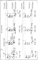
- Figs. 2A to 2H are schematic diagrams showing the operation and the returning of the return mechanism 50 according to the present embodiment.
- a user applies an operational force as an external force to the operation unit 11 to move the operation unit 11.
- the actuation unit 12 is displaced as the operation unit 11 is displaced.
- the return mechanism 50 functions.
- a power generator included in the switch device generates power as the actuation unit 12 moves, as described later.
- the switch device uses the generated power to externally output a signal indicating that the operation unit 11 has been operated.
- Fig. 2A shows the initial state of the return mechanism 50.
- spring forces acting on the operation unit 11 and the actuation unit 12 are indicated by arrows, each with the length not exactly showing the magnitude of the force.
- the actuation unit 12 In the initial state, no external force is applied to the operation unit 11.
- the actuation unit 12 In the initial state, the actuation unit 12 is retained at the third position under a restoring force of the compressed third spring 3, a restoring force of the deformed second spring 2, and the retaining force (not shown).
- the operation unit 11 is pressed against the first position under a restoring force of the compressed first spring 1.
- the actuation unit 12 has an angle ⁇ 1 at the third position.
- the angle ⁇ is formed between the direction in which the actuation unit 12 (joint 12b) returns and the direction in which the second spring 2 applies its restoring force to the actuation unit 12.
- the restoring force of the second spring 2 acting on the actuation unit 12 includes a force component cos ⁇ 1 along the stroke axis S (component in the direction in which the actuation unit 12 moves).
- the force acting upward on the actuation unit 12 (force acting in the direction in which the actuation unit 12 returns) is positive.
- Fig. 2B shows the operation unit 11 displaced under a force applied for operating the operation unit 11 (operational force).
- the operational force applied as an external force to the operation unit 11 displaces the operation unit 11 from the first position to the second position.
- the first spring 1 is compressed as the operation unit 11 is displaced.
- the restoring force of the compressed first spring 1 exceeds the sum of the restoring force of the second spring 2, the restoring force of the third spring 3, and the retaining force, which act on the actuation unit 12, the restoring force of the compressed first spring 1 displaces the actuation unit 12 from the third position to the fourth position ( Fig. 2C ).
- the actuation unit 12 displaced to the fourth position is retained at the fourth position under the retaining force ( Fig. 2D ).
- the second spring 2 changes its orientation (the second spring 2 rotates) to change the direction of its restoring force.
- the second spring 2 applies a force to the actuation unit 12 at the third position in a direction that is not parallel to a direction in which the second spring 2 applies a force to the actuation unit 12 at the fourth position.
- the actuation unit 12 has an angle ⁇ 2 at the fourth position.
- the restoring force of the second spring 2 acting on the actuation unit 12 includes a force component cos ⁇ 2 along the stroke axis S.
- the restoring force of the second spring 2 acting on the actuation unit 12 includes a force component along the stroke axis S (force component having a direction in which the actuation unit 12 returns defined as positive) that is smaller when the actuation unit 12 is at the fourth position than when the actuation unit 12 is at the third position, showing a monotonic decrease.
- the actuation unit 12 is moved by the first spring 1 when the restoring force of the compressed first spring 1 exceeds the sum of the component of the restoring force of the second spring 2 along the stroke axis S, the restoring force of the third spring 3, and the retaining force, and the accumulated elastic energy is released.
- the actuation unit 12 is moved by the first spring 1 at high speed independently of the moving speed of the operation unit 11.
- the operation unit 11 starts moving from the second position toward the first position under the restoring force of the compressed first spring 1 ( Fig. 2E ).
- the actuation unit 12 is retained at the fourth position under the retaining force and the restoring force of the first spring 1.
- the restoring force of the first spring 1 gradually decreases as the operation unit 11 is displaced.
- the operation unit 11 then moves to the first position ( Fig. 2F ).
- an upward force of the second spring 2 increases gradually.
- the actuation unit 12 starts moving, and then accelerates further.
- the second spring 2 also moves the actuation unit 12 at high speed when the actuation unit 12 returns. This completes the movement of the operation unit 11 and the actuation unit 12 during returning.
- the actuation unit 12 is moved by the third spring 3 when elastic energy accumulated in the third spring 3 is released. In other words, the actuation unit 12 is moved by the third spring 3 at high speed independently of the returning speed of the operation unit 11.
- the third spring 3, which causes the actuation unit 12 to return, may be eliminated.
- the restoring force of the second spring 2 can cause the actuation unit 12 at the fourth position to return to the third position when the restoring force of the second spring 2 includes a force component along the stroke axis S that is upward ( ⁇ 2 ⁇ 90°) and is greater than the sum of the retaining force and the restoring force of the first spring 1.
- the angle ⁇ 1 at the third position may be greater than 90°.
- Fig. 3 is a diagram showing the structure of the return mechanism 50 according to the present embodiment and its force-stroke (FS) characteristics.
- the horizontal axis indicates the stroke S of the operation unit 11, and the vertical axis indicates the force F.
- Fig. 3 shows the operational force.
- the operational force equal to the repulsive force of the first spring 1 is to be applied at each stroke position.
- the force being positive refers to the force being upward applied to the operation unit 11 (a direction from the second position to the first position).
- the operational force to be applied may be an upward force (return force) that causes the operation unit 11 to return.
- the retaining force acting on the actuation unit 12 allows for the hysteresis FS characteristics.
- the first position of the operation unit 11 may be between a top dead center (S0) of the operation unit 11 and a stroke S1.
- the second position of the operation unit 11 may be between a stroke S2 and a bottom dead center (S3) of the operation unit 11.
- An operational force applied to the operation unit 11 displaces the operation unit 11 from the top dead center (S0).
- the operation unit 11 reaches the stroke S2
- the restoring force of the compressed first spring 1 exceeds the sum (resultant force) of the retaining force of the actuation unit 12 at the third position, the force of the second spring 2, and the force of the third spring 3.
- the actuation unit 12 is thus displaced from the third position to the fourth position. This displacement frees the compressed first spring 1.
- the operational force decreases at the same time.
- the force of the first spring 1 causes the operation unit 11 to return.
- the operation unit 11 returns from the second position toward the first position, the first spring 1 is compressed by a lesser degree.
- the restoring force of the third spring 3 exceeds the sum of the retaining force of the actuation unit 12 at the fourth position, the force of the second spring 2, and the force of the first spring 1.
- the actuation unit 12 is thus displaced from the fourth position to the third position. This displacement compresses the first spring 1.
- the return force increases at the same time.
- the return mechanism 50 includes the second spring 2.
- This structure uses a larger operational force to be applied to the operation unit 11 to displace the actuation unit 12 from the third position to the fourth position than the structure without the second spring 2.
- the force of the second spring 2 includes a smaller force component along the stroke axis S when the direction in which the actuation unit 12 returns from the fourth position to the third position is defined as positive.
- Setting a greater moving distance (stroke) for the actuation unit 12 causes the first spring 1 to be compressed by a still lesser degree.
- the operational force decreases more in the stroke S2.
- the hatched area in the figure shows the energy applied to the actuation unit 12 during operation and during returning.
- the return mechanism 50 can apply greater energy to the actuation unit 12.
- the return mechanism 50 can move the actuation unit 12 at high speed.
- the actuation unit 12 of the return mechanism 50 is combined with a power generator to generate power. This increases the kinetic energy of the actuation unit 12, and thus increases the amount of power generation.
- This structure can also increase the amount of power generation (allows the actuation unit to move at high speed) without increasing the magnetic force (retaining force) from a magnet included in the power generator.
- the return mechanism 50 used in a switch device enables a high-speed switching operation.
- the return mechanism 50 may be used as a switch device when its actuation unit 12 includes a movable contact for an electrode terminal.
- the contact can be open quickly. This structure shortens the period in which an arc occurs between the contacts, and can reduce wear.
- the second spring 2 may not be connected to the actuation unit 12 and the movable unit 13 in a fixed manner.
- the second spring 2 may be at least arranged between the actuation unit 12 and the movable unit 13 to apply a repulsive force to these units.
- Each of the operation unit 11 and the actuation unit 12 may include a plurality of components.
- the return mechanism 50 may include the first spring 1 that is stretched during operation and is compressed during returning.
- the operation unit 11 and the first spring 1 shown in Fig. 1 may be arranged opposite to the actuation unit 12.
- the first spring 1 is stretched as the operation unit 11 is displaced downward (toward the second position).
- the stretched first spring 1 displaces the actuation unit 12 downward (toward the fourth position).
- the operation unit 11 and the first spring 1 may be connected using another component, such as a plunger.
- the first spring 1 (or the second spring 2 or the third spring 3) and the actuation unit 12 may also be connected using another component.
- Fig. 4 is a perspective view of a torsion coil spring as the second spring 2 showing its detailed structure.
- the second spring 2 includes two coil portions 2c, two arms 2d, and a connecting arm 2e.
- the two coil portions 2c have coaxial axis portions 2a.
- the two coil portions 2c are connected by the connecting arm 2e, which is substantially U-shaped, and extends externally from one of the coil portions 2c and bends toward the other coil portion 2c.
- the arms 2d extend in the same direction from the opposite sides of the coil portions 2c.
- the coil portions 2c are wound in opposite directions.
- the positions of the two arms 2d and the connecting arm 2e may be reversed.
- the connecting arm 2e may not be U-shaped but may have any other shape that extends externally from the two coil portions 2c and connects the two coil portions 2c.
- Fig. 5 is a perspective view of the return mechanism 50 showing the detailed structure of the actuation unit 12, the movable units 13, the first base 14, and the second springs 2. Fig. 5 does not show the operation unit 11, the first spring 1, the third spring 3, and the second base 15.
- Two pairs of the second springs 2 and the movable units 13 are arranged symmetric to each other on both sides of the actuation unit 12.
- the two second springs 2 arranged symmetric to each other on both sides of the actuation unit 12 can cancel components of the restoring forces of the second springs 2 perpendicular to the stroke axis S. This reduces a friction force acting on the actuation unit 12.
- a shaft 16 is placed through a hole in each movable unit 13 (axis portion 2a) and the coil portions 2c of each second spring 2.
- a shaft 17 is placed through another hole in each movable unit 13 (axis portion 13a) and a hole in the first base 14.
- each of the shafts 16 and 17 has a flange at one end, and an E-ring at the other end.
- the movable units 13 and the first base 14 have the holes with closed ends. This structure prevents the shafts 16 and 17 placed in these holes from being removed under, for example, impact.
- the shaft 16 placed through the two coil portions 2c of each second spring 2 prevents misalignment of the axes of the two coil portions 2c under a force applied to the second spring 2.
- the second springs 2 can allow stable operation and achieve a longer lifetime.
- Each movable unit 13 has two ridges (a support 18 and a position regulating ridge 19) on its side surface at one end. Each movable unit 13 further has a support 18 and a position regulating ridge 19 on its side surface at the other end.
- the arms (ends 2b) on one side of each second spring 2 are between the support 18 and the position regulating ridge 19.
- the support 18 supports the arms on one side of each second spring 2 while receiving a force from the arms.
- the position regulating ridges 19 are at positions where no force is applied from the arms.
- the arms, which are placed between the position regulating ridge 19 and the support 18, are prevented from being removed from the movable unit 13 when the switch device receives a large impact.
- each position regulating ridge 19 can ease the assembly of the switch device.
- the connecting arm 2e of each second spring 2 is between two ridges on the actuation unit 12. The positions of the connecting arm 2e and the arms 2d may be reversed.
- Each second spring 2 includes the two coil portions 2c arranged on both sides of the central connecting arm 2e.
- the two coil portions 2c are supported by the shaft 16.
- the two arms 2d extend externally from the two coil portions 2c.
- the two arms 2d are supported by the support 18 on each movable unit 13.
- the central connecting arm 2e supported on its both sides is prevented from being twisted with respect to the axis of the second spring 2.
- the second springs 2 allow the actuation unit 12 to operate in a stable manner.
- the two second springs 2 are arranged symmetric to each other with respect to the actuation unit 12. In total, the four coil portions 2c surround the center of gravity of the actuation unit 12.
- the two second springs 2 can thus apply forces to the actuation unit 12 in a stable manner.
- Each connecting arm 2e supported by the two coil portions 2c on its both sides is less likely to be twisted.
- the second springs 2 each having the connecting arms 2e are appropriately fixed to the movable units 13 that rotate.
- the two second springs 2 may not be used.
- a single second spring 2 may be used to move the actuation unit 12.
- each second spring 2 includes the two coil portions 2c connected by the connecting arm 2e
- the second spring 2 may have another structure.
- the second spring 2 may include two torsion coil springs that are separate at the center of the connecting arm 2e, or may simply be a single torsion coil spring having two arms and a single coil portion.
- the first base 14 includes a guide groove 14a for guiding the sliding actuation unit 12.
- the actuation unit 12 partly fits in the guide groove 14a. This structure prevents the actuation unit 12 from being twisted.
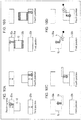
- Figs. 6A to 6C are front views of the actuation unit 12 for describing its movement.
- Fig. 6A shows the initial state of movement.
- Fig. 6B shows the intermediate state of movement.
- Fig. 6C shows the state of completed movement.
- Fig. 6A shows the initial state ( Fig. 6A ).
- the actuation unit 12 starts moving downward.
- Fig. 6B shows the actuation unit 12 that is moving.
- the connecting arms 2e are depressed while receiving a torque. This deflects (elastically deforms) the second springs 2. This movement changes the angle between the connecting arm 2e and the arms 2d, and also causes the second spring 2 and the movable unit 13 to rotate about the shaft 17.
- Fig. 6C shows the state of the completely moved actuation unit 12, or the actuation unit 12 at the fourth position.
- the axes of the second springs 2 (the positions of the shafts 16) move downward.
- This also changes the angle of each arm 2d fixed to each movable unit 13 in the same direction of rotation as the angle of the connecting arm 2e.
- the connecting arm 2e has its top end in contact with the side surface of the actuation unit 12, and can be displaced in accordance with the movement of the actuation unit 12. This extends the stroke of the actuation unit 12 in the present embodiment, as compared with the structure in which the axes of the second springs 2 and the positions of the arms 2d are fixed.
- Fig. 7 is a front view of an actuation unit 112 according to a reference example showing its structure.
- Torsion coil springs 102 are arranged on both sides of the actuation unit 112.
- Each torsion coil spring 102 includes a connecting arm 102e engaged in the recess in the actuation unit 112, and the other arm 102d engaged in the recess in a base 114.
- the base 114 is fixed.
- Each torsion coil spring 102 includes a coil portion (axis) fixed to the base 114.
- the distance between the pivot of each connecting arm 102e (the position at which the coil is connected) and the corresponding recess in the actuation unit 112 changes.
- the structure of the reference example thus cannot extend the stroke of the actuation unit 112.
- Forcibly extending the stroke of the actuation unit 112 in this structure can greatly deform the torsion coil springs 102, and shorten the lifetime of the torsion coil springs 102.
- longer connecting arms 102e are to be used to place the axes of the torsion coil springs 102 more away from the actuation unit 112.
- torsion coil springs 102 can increase the size of the switch device.
- the arms 102d can change their orientations (angles) as the actuation unit 112 is displaced.
- the recesses in the base 114 in contact with the arms 102d can wear. This can lower the durability.
- the movable units 13 are arranged between the actuation unit 12 and the first base 14.
- the second springs 2 that are torsion coil springs act between the actuation unit 12 and the movable units 13.
- the movable units 13 move as the actuation unit 12 is displaced. This structure can reduce the size of the switch device and extend the lifetime of the second springs 2, while extending the stroke of the actuation unit 12.
- the second springs 2 accelerate the actuation unit 12, and thus increase the amount of power generation.
- each second spring 2 The arms 2d of each second spring 2 are fixed between the support 18 and the position regulating ridge 19.
- the angle of each arm 2d with the movable unit 13 is fixed, causing no sliding between the arm 2d and the movable unit 13 when the actuation unit 12 is displaced. This prevents wear of the arms 2d and the movable units 13.
- the movable unit 13 increases the angle between the connecting arm 2e and each arm 2d (to near a straight line). A relatively large angle between the connecting arm 2e and each arm 2d eases the assembly.
- the use of other springs e.g., plate springs or compression coil springs replacing the second springs 2 for achieving the long lifetime and the long stroke as in the present embodiment may need large plate springs or compression coil springs.
- the torsion coil springs may be used as in the present embodiment.
- each movable unit 13 may be arranged between each movable unit 13 and the first base 14.
- another movable unit (second movable unit) may be arranged between each movable unit 13 and the first base 14.
- each movable unit 13 rotates relative to the connected second movable unit
- the second movable unit rotates relative to the connected first base 14.
- Another torsion coil spring may be arranged between each movable unit 13 and the second movable unit.
- the other torsion coil spring may have its one arm fixed to each movable unit 13, and the other arm fixed to the second movable unit.
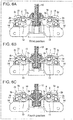
- Fig. 8 is a perspective view of a power generator 46 showing its structure.
- the switch device includes the return mechanism 50, the power generator 46, and a transmitter.
- the power generator 46 includes an armature 41, a coil 42, two yokes 43a and 43b, and a magnet 44.
- the armature 41 is connected to the actuation unit 12 with, for example, a plunger, and moves together with the actuation unit 12.
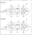
- Figs. 9A and 9B are front views of the power generator 46 showing its structure.
- Fig. 9A shows the power generator 46 when the actuation unit 12 is at the third position.
- Fig. 9B shows the power generator 46 when the actuation unit 12 at the fourth position.
- the armature 41 is formed from a ferromagnetic material such as iron.
- the armature 41 is U-shaped.
- the armature 41 is rotatable about a pivot around the center (around the magnet 44) between the two yokes 43a and 43b.
- the armature 41 rotates between the two yokes 43a and 43b as the actuation unit 12 is displaced.
- the two yokes 43a and 43b are magnetized by the magnet 44 (permanent magnet) arranged between the yokes 43a and 43b.
- the armature 41 is placed through the coil 42.
- the armature 41 When the actuation unit 12 is at the third position (the state shown in Fig. 9A ), the armature 41 has its one end in contact with the yoke 43a, and has its other end in contact with the yoke 43b. The armature 41 is retained at this position (a position corresponding to the third position) under the magnetic force (retaining force) acting on these two ends. The actuation unit 12, which moves in cooperation with the armature 41, is also retained at the third position. The armature 41 can be a part of the actuation unit 12.
- the armature 41 When the actuation unit 12 is at the fourth position (the state shown in Fig. 9B ), the armature 41 has its one end in contact with the yoke 43b, and has its other end in contact with the yoke 43a. The armature 41 is retained at this position (a position corresponding to the fourth position) under the magnetic force (retaining force) acting on these two ends. The actuation unit 12, which moves in cooperation with the armature 41, is also retained at the fourth position.
- the opposing faces of the two yokes 43a and 43b have opposite magnetic poles.
- the magnetizing direction of the armature 41 is reversed. This reverses the direction of the magnetic flux passing through the coil 42, causing an inductive current to flow through the coil 42 in accordance with the variation in the magnetic flux.
- the power generator 46 generates power in this manner. A greater change in the magnetic flux per unit time causes a larger inductive current to flow.
- the return mechanism 50 in the switch device uses the first spring 1 and the second springs 2 to move the actuation unit 12 at high speed, and thus allows highly efficient power generation.
- the structure also extends the stroke of the actuation unit 12, and thus allows highly efficient power generation.
- the coil 42 is connected to the transmitter (not shown) with, for example, lead wires.
- the transmitter uses power generated by the coil 42 to transmit signals to an external device either wirelessly or with wires.
- the transmitter transmits, to the external device, a signal indicating that the operation unit 11 is at the second position (or the actuation unit 12 is at the fourth position).
- the transmitter transmits, to the external device, a signal indicating that the operation unit 11 is at the first position (or the actuation unit 12 is at the third position).
- the switch device functions as a switch for transmitting a signal corresponding to the position of the operation unit 11 or the position of the actuation unit 12 to the external device.
- the switch device can be used as a switch, such as an operation switch operable by a user, or a limit switch (detection switch) for detecting the position of an object.
- the transmitter may transmit a predetermined signal using generated power independently of the position of the operation unit 11 or the actuation unit 12.
- the power generator 46 and the return mechanism 50 may simply be used as a power generator.
- the switch device may include a battery or an external power supply, instead of the power generator 46.
- the transmitter generates a signal corresponding to the position of the actuation unit 12 using power supplied from the battery or the external power supply.
- the operation unit 11 may be directly operable by a user or an object for which its position is to be detected, or may be indirectly operated. For example, the rotational operation of a lever operated by a user may be converted into the movement of the operation unit 11.
- Figs. 10A to 10D are diagrams describing retaining forces in examples.
- Fig. 10A shows a magnetic force used as a retaining force.
- a return mechanism includes two magnets 21a and 21b facing each other with an actuation unit 12 between them.
- the actuation unit 12 is formed from a ferromagnetic material.
- the actuation unit 12 at the third position is retained at the third position under a magnetic force of the upper magnet 21a.
- the actuation unit 12 at the fourth position is retained at the fourth position under a magnetic force of the lower magnet 21b.
- the two magnets 21a and 21b may be joined to each other at a position not shown in the figure.
- Fig. 10B shows an adhesive force used as a retaining force.
- a return mechanism includes two supports 22a and 22b facing each other with an actuation unit 12 between them.
- the actuation unit 12 includes adhesive members 23a and 23b on its upper and lower surfaces.
- the adhesive members 23a and 23b are adhered to supports 22a and 22b to retain the actuation unit 12 at the third position and the fourth position.
- the adhesive members 23a and 23b may be arranged on the opposing surfaces of the two supports 22a and 22b.
- Fig. 10C shows a snap fit used as a holding mechanism.
- a return mechanism includes two supports 22a and 22b facing each other with an actuation unit 12 between them.
- the return mechanism includes an elastic body 24 that presses the actuation unit 12 against the third position or the fourth position. As the actuation unit 12 moves, the elastic body 24 deforms elastically.
- Fig. 10D shows a spring force used as a retaining force.
- a return mechanism includes two supports 22a and 22b facing each other with an actuation unit 12 between them, and a fifth spring 5.
- the fifth spring 5 has its one end fixed to another member, and its other end connected to the actuation unit 12. When the actuation unit 12 is at the third position, the fifth spring 5 is compressed to apply a restoring force acting upward. When the actuation unit 12 is at the fourth position, the fifth spring 5 is compressed to apply a restoring force acting downward.
- the second spring 2 may replace the fifth spring 5.
- the retaining force may act on the actuation unit 12 at one of the third position and the fourth position, and may not act on the actuation unit 12 at the other position.
- the actuation unit 12 moves at high speed with the first spring 1 during operation, whereas the actuation unit 12 returns at a speed corresponding to the speed of the operation unit 11 during returning.
- the actuation unit 12 moves at a speed corresponding to the speed of the operation unit 11 during operation, whereas the actuation unit 12 returns at high speed with the first spring 1 during returning.
- No retaining force may act on the actuation unit at both the third position and the fourth position.
- the actuation unit 12 can be accelerated by the varying component of the force of the second spring 2 along the stroke axis S as the actuation unit 12 moves.
- the operation unit 11 and the first spring 1 may be eliminated, and a user may operate the actuation unit 12.
- a switch device differs from the switch device according to the first embodiment in a fourth spring for returning movement, which replaces the third spring.
- FIGs. 11A to 11H are schematic diagrams showing the operation and the returning of a return mechanism 51 included in the switch device according to the present embodiment.
- a fourth spring 4 allows an operation unit 11 and an actuation unit 12 to self-return.
- the return mechanism 51 (acceleration mechanism) includes the operation unit 11, the actuation unit 12, a movable unit 13, a first base 14 (not shown), a second base 15, a first spring 1, a second spring 2, and the fourth spring 4.
- the fourth spring 4 connects the operation unit 11 and the second base 15.
- the fourth spring 4 applies a force to the operation unit 11 in a direction parallel to a direction in which the operation unit 11 is movable.
- the operation unit 11 is displaced between a first position and a second position in accordance with an operational force
- the actuation unit 12 is displaced between a third position and a fourth position.
- the fourth spring 4 causes the operation unit 11 to return from the second position to the first position.
- the stretched first spring 1 pulls the actuation unit 12 to cause the actuation unit 12 to return from the fourth position to the third position.
- the second spring 2 (torsion coil spring) has a force acting obliquely to the direction in which the actuation unit 12 is movable.
- the restoring force of the second spring 2 acting on the actuation unit 12 includes a force component along a stroke axis S (force component having a direction in which the actuation unit 12 returns defined as positive) that is smaller when the actuation unit 12 is at the fourth position than when the actuation unit 12 is at the third position, showing a monotonic decrease.
- the repulsive force of the second spring 2 decreases gradually.
- the actuation unit 12 starts moving, and then accelerates further.
- the actuation unit 12 starts moving from the fourth position to the third position, and then accelerates under an increasing force component of the second spring 2 along the stroke axis S.
- Fig. 11A shows the initial state of the return mechanism 51.
- spring forces acting on the operation unit 11 and the actuation unit 12 are indicated by arrows, each with the length not exactly showing the magnitude of the force.
- the actuation unit 12 In the initial state, no external force is applied to the operation unit 11.
- the actuation unit 12 In the initial state, the actuation unit 12 is retained at the third position under a restoring force (repulsive force) of the deformed second spring 2, and the retaining force (not shown).
- the operation unit 11 is pressed against the first position under a restoring force of the compressed first spring 1 and a restoring force of the compressed fourth spring 4.
- Fig. 11B shows the operation unit 11 displaced under a force applied for operating the operation unit 11 (operational force).
- the operational force applied as an external force to the operation unit 11 displaces the operation unit 11 from the first position to the second position.
- the first spring 1 is compressed as the operation unit 11 is displaced.
- the restoring force of the compressed first spring 1 exceeds the sum of the restoring force of the second spring 2 and the retaining force, which act on the actuation unit 12, the restoring force of the compressed first spring 1 displaces the actuation unit 12 from the third position to the fourth position ( Fig. 11C ).
- the actuation unit 12 displaced to the fourth position is retained at the fourth position under the retaining force ( Fig. 11D ).
- the second spring 2 changes its orientation (the second spring 2 rotates) to change the direction of its restoring force.
- the restoring force of the second spring 2 acting on the actuation unit 12 includes a force component along the stroke axis S (force component having a direction in which the actuation unit 12 returns defined as positive) that is smaller when the actuation unit 12 is at the fourth position than when the actuation unit 12 is at the third position, showing a monotonic decrease.
- the repulsive force of the second spring 2 decreases gradually.
- the actuation unit 12 starts moving, and then accelerates further. This completes the movement of the operation unit 11 and the actuation unit 12 during operation.
- the operation unit 11 When the operational force on the operation unit 11 is eliminated, the operation unit 11 starts moving from the second position to the first position under the restoring force of the compressed fourth spring 4 ( Fig. 11E ). In this state, the actuation unit 12 is retained at the fourth position under the retaining force and the restoring force of the first spring 1.
- the first spring 1 When the operation unit 11 returns to the first position, the first spring 1 stretches longer than its equilibrium length ( Fig. 11F ). The restoring force of the stretched first spring 1 acts in a direction to pull the actuation unit 12 upward. When the restoring force of the stretched first spring 1 exceeds the sum of the component of the restoring force of the second spring 2 acting on the actuation unit 12 along the stroke axis S and the retaining force, the restoring force of the stretched first spring 1 displaces the actuation unit 12 from the fourth position to the third position ( Fig. 11G ). Although the first spring 1 is compressed while the actuation unit 12 is returning, the component of the restoring force of the second spring 2 along the stroke axis S acts upward on the actuation unit 12. The operation unit 11 thus returns to the third position ( Fig. 11H ). This completes the movement of the operation unit 11 and the actuation unit 12 during returning.
- the actuation unit 12 is moved by the first spring 1 when the elastic energy accumulated in the first spring 1 is released. In other words, the actuation unit 12 is moved by the first spring 1 at high speed independently of the returning speed of the operation unit 11.
- the operation unit 11 in each of the return mechanisms 50 and 51 may rotate. As the operation unit 11 rotates, the first spring 1 connected at an operation point of the operation unit 11 is either compressed or stretched. Summary
- a switch device is switchable in accordance with a position of an actuation unit.
- the switch device includes the actuation unit, a movable unit, a base, and a torsion coil spring that acts between the actuation unit and the movable unit.
- the movable unit is movable with respect to the base supporting the movable unit.
- the actuation unit is movable between a first actuation position and a second actuation position.
- the torsion coil spring When the actuation unit is at the first actuation position, the torsion coil spring applies a force to the actuation unit in a direction that is not parallel to a direction in which the torsion coil spring applies a force to the actuation unit when the actuation unit is at the second actuation position.
- the direction in which the torsion coil spring applies a force to the actuation unit changes in accordance with the position of the actuation unit (actuation position).
- the movable unit can move in accordance with the movement of the actuation unit (in accordance with the direction of the force of the torsion coil spring).
- the torsion coil spring can have less deflection as the actuation unit moves. This can extend the stroke of the actuation unit.
- the torsion coil spring with less deflection can be smaller. This can reduce the size of the switch device, and can also extend the stroke of the actuation unit.
- the torsion coil spring may have an arm fixed to the movable unit.
- the torsion coil spring and the movable unit move together as the actuation unit moves.
- the torsion coil spring can thus have less deflection as the actuation unit moves. This allows a longer stroke to be set for the actuation unit.
- the movable unit may include a position regulating ridge, and a support that receives a force from the arm of the torsion coil spring.
- the arm of the torsion coil spring may be between the support and the position regulating ridge.
- the arm of the torsion coil spring is between the support and the position regulating ridge and is thus prevented from being removed under impact.
- This structure also prevents the arm from being removed from the movable unit during the assembly of the switch device, and thus improves the workability in the assembly.
- the movable unit may be rotatable with respect to the base in accordance with movement of the actuation unit.
- the movable unit rotates in accordance with the movement of the actuation unit.
- the torsion coil spring can thus have less deflection as the actuation unit moves.
- the movable unit may be fixed to the base in a rotatable manner with a shaft placed through the movable unit and the base.
- the shaft is placed through the movable unit and the base to prevent the movable unit from being removed from the base under, for example, impact.
- the torsion coil spring may have an axis portion fixed to the movable unit.
- the torsion coil spring may have an axis portion fixed to the movable unit with a shaft placed through a coil portion of the torsion coil spring.
- the axis portion of the torsion coil spring is fixed to the movable unit. This structure prevents the axis portion of the torsion coil spring from being twisted (changing the axis orientation).
- the torsion coil spring can thus apply a force to the actuation unit in a stable manner.
- the torsion coil spring may include two coil portions that are coaxial, a connecting arm connecting the two coil portions, and two arms extending from the respective two coil portions.
- the connecting arm can be supported by the two coil portions. This stabilizes the direction in which the connecting arm applies a force to the actuation unit.
- the torsion coil spring may apply a force including, in a moving direction of the actuation unit, a force component that is smaller when the actuation unit is at the second actuation position than when the actuation unit is at the first actuation position.
- the force component has a direction in which the actuation unit returns from the second actuation position to the first actuation position defined as positive.
- the component of the force of the torsion coil spring in the direction in which the actuation unit moves is smaller when the actuation unit is at the second actuation position than when the actuation unit is at first actuation position.
- the actuation unit starts moving and then can accelerate further.
- the switch device may include an operation unit, and an acceleration spring that acts between the operation unit and the actuation unit.
- the operation unit may move under an external force from a first operation position to a second operation position.
- the actuation unit may move between the first actuation position and the second actuation position in accordance with movement of the operation unit between the first operation position and the second operation position.
- the acceleration spring may move the actuation unit with elastic energy accumulated under an external force applied to the operation unit.
- the actuation unit When the actuation unit is at the first actuation position and/or the second actuation position, the actuation unit may receive a retaining force for retaining the actuation unit at the first actuation position and/or the second actuation position.
- the switch device may include a magnet, and a coil that induces a current by varying a magnetic flux of the magnet passing through the coil in accordance with movement of the actuation unit.
- the actuation unit can move to generate power.
- the present invention is applicable to switch devices.
Description
- The present invention relates to a switch device.
- A switch device switches in accordance with the position of a member that moves in response to an operation. The switch device typically includes a spring to allow the moving member to return to its original position.
- A switch device described in
Patent Literature 1 includes a compression coil spring for resetting a movable contact, and a plate spring for adjusting an operation load. The plate spring with a particular shape arranged at a particular position can achieve a snap action. - Patent Literature 1: Japanese Unexamined Patent Application Publication No.
2007-227308 (published on September 6, 2007 - A switch device according to the preamble of
claim 1 is known fromJP 5 679093 B1 -
JP 5 679093 B1 - Documents
JP 2007 227308 A CN 1 151 602 ADE 23 03 332 A1 ;US 4 112 284 A ;EP 2 151 837 A2 ;EP 2 362 403 A1 andEP 1 182 673 A2 are further examples of related art. - A switch device incorporating a power generator intends to have more power. The power generator generates power by moving its member in response to an operation. Setting a longer stroke for the member that moves in response to an operation increases the amount of power generation. A switch device incorporating a power generator may thus need a longer stroke set for a member that moves in response to an operation. A switch device including no power generator may also need a longer stroke set for a member that moves in response to an operation.
- A compression coil spring or a plate spring used for returning movement can increase the size of the switch device. A smaller compression coil spring or a smaller plate spring cannot achieve an intended lifetime, operation load, and stroke.
- One or more aspects of the present invention are directed to a switch device that is small and has a longer stroke for a member that moves in response to an operation.
- A switch device according to one or more aspects of the present invention is switchable in accordance with a position of an actuation unit. The switch device includes the actuation unit, a movable unit, a base, and a torsion coil spring that acts between the actuation unit and the movable unit. The movable unit is movable with respect to the base supporting the movable unit. The actuation unit is movable between a first actuation position and a second actuation position, and when the actuation unit is at the first actuation position, the torsion coil spring applies a force to the actuation unit in a direction that is not parallel to a direction in which the torsion coil spring applies a force to the actuation unit when the actuation unit is at the second actuation position.
- Embodiments of the present invention can set a longer stroke for an actuation unit and can reduce the size of a switch device.
-
-
Fig. 1 is a schematic diagram of a return mechanism included in a switch device according to one embodiment of the present invention. -
Figs. 2A to 2H are schematic diagrams showing the operation and the returning of the return mechanism. -
Fig. 3 is a diagram showing the structure of the return mechanism and its force-stroke (FS) characteristics. -
Fig. 4 is a perspective view of a torsion coil spring as a second spring showing its detailed structure. -
Fig. 5 is a perspective view of the return mechanism showing the detailed structure of an actuation unit, movable units, a first base, and second springs. -
Figs. 6A to 6C are front views of the actuation unit for describing its movement. -
Fig. 7 is a front view of an actuation unit according to a reference example showing its structure. -
Fig. 8 is a perspective view of a power generator included in the switch device according to the embodiment of the present invention. -
Figs. 9A and 9B are front views of the power generator showing its structure. -
Figs. 10A to 10D are diagrams describing retaining forces in examples. -
Figs. 11A to 11H are schematic diagrams showing the operation and the returning of a return mechanism included in a switch device according to another embodiment of the present invention. - For ease of explanation, components with the same functions are given the same numerals, and may not be described.
- A switch device according to one embodiment includes a power generator, a transmitter, and a return mechanism for an operation unit. The structure of the return mechanism will first be described schematically. Structure of
Return Mechanism 50 -
Fig. 1 is a schematic diagram (dynamic model) of areturn mechanism 50 according to the present embodiment. Thereturn mechanism 50 includes anoperation unit 11 and anactuation unit 12, which both self-return. Theactuation unit 12 moves at high speed independently of the speed at which theactuation unit 12 is operated. Asecond spring 2 enables theactuation unit 12 to move at high speed. Athird spring 3 enables theoperation unit 11 and theactuation unit 12 to self-return. - The return mechanism 50 (acceleration mechanism) includes the
operation unit 11, theactuation unit 12, amovable unit 13, a first base 14 (base), asecond base 15, a first spring 1 (acceleration spring), thesecond spring 2, and the third spring 3 (return spring). Thefirst spring 1 connects theoperation unit 11 and theactuation unit 12. Thesecond spring 2 connects theactuation unit 12 and themovable unit 13. Thethird spring 3 connects theactuation unit 12 and thesecond base 15. Thefirst spring 1 and thethird spring 3 may be any springs, such as coil springs, torsion coil springs, or plate springs. Thesecond spring 2 is a torsion coil spring having anaxis portion 2a (coil shaft) andends 2b at one side (arms at one side) fixed to themovable unit 13. Themovable unit 13 is supported by thefirst base 14 and is movable with respect to thefirst base 14. More specifically, themovable unit 13 is rotatable about anaxis portion 13a. Thefirst base 14 and thesecond base 15 are stationary. Thefirst base 14 and thesecond base 15 may be an integral single component, or may be separate components. Themovable unit 13 rotates about theaxis portion 13a fixed to thefirst base 14. Theaxis portion 2a and theends 2b of thesecond spring 2 are fixed to themovable unit 13. The relative positions of theaxis portion 2a and theends 2b of thesecond spring 2 and theaxis portion 13a remain unchanged. - The
operation unit 11 and theactuation unit 12 are movable along a stroke axis S. Thefirst spring 1 applies a force to theoperation unit 11 in a direction parallel to a direction in which theoperation unit 11 is movable. Thethird spring 3 applies a force to theactuation unit 12 in a direction parallel to a direction in which theactuation unit 12 is movable. - The
second spring 2 applies a force to theactuation unit 12 in a direction diagonal to the direction in which theactuation unit 12 is movable. The direction in which thesecond spring 2 applies a force to theactuation unit 12 and the stroke axis S form an angle η. Theaxis portion 13a fixed to thefirst base 14 does not move. Thesecond spring 2 has the other end (arm at the other side) that is connected to theactuation unit 12 and moves as theactuation unit 12 moves. The angle η thus changes as theactuation unit 12 moves along the stroke axis S. - The
operation unit 11 has anoperation point 11a, which is used as a reference of displacement of theoperation unit 11. When theoperation unit 11 translates under an external force, a point on theoperation unit 11 also translates. In this translation, theoperation point 11a may be any point on theoperation unit 11. Similarly, theactuation unit 12 has anaction point 12a, which also translates, used as a reference of displacement of theactuation unit 12. - The
operation point 11a on theoperation unit 11 is displaceable along the stroke axis S between a first position (first operation position) and a second position (second operation position). Theaction point 12a on theactuation unit 12 is displaceable along the stroke axis S between a third position (first actuation position) and a fourth position (second actuation position). Theactuation unit 12 is connected to thesecond spring 2 at a joint 12b. The joint 12b, at which theactuation unit 12 is connected to thesecond spring 2, is displaced together with theactuation unit 12 in the same directions as the directions in which thefirst spring 1 stretches and contracts. - When the
action point 12a is at the third position, a retaining force acts on theactuation unit 12 to retain theaction point 12a at the third position. When theaction point 12a is at the fourth position, a retaining force acts on theactuation unit 12 to retain theaction point 12a at the fourth position. More specifically, theactuation unit 12 is retained at the third position or the fourth position under a magnetic force acting at that position. - For convenience, the
operation point 11a being at the first position may be referred to as theoperation unit 11 being at the first position. The same applies to theaction point 12a and theactuation unit 12. -
Figs. 2A to 2H are schematic diagrams showing the operation and the returning of thereturn mechanism 50 according to the present embodiment. A user applies an operational force as an external force to theoperation unit 11 to move theoperation unit 11. Theactuation unit 12 is displaced as theoperation unit 11 is displaced. As theactuation unit 12 moves, thereturn mechanism 50 functions. For example, a power generator included in the switch device generates power as theactuation unit 12 moves, as described later. The switch device uses the generated power to externally output a signal indicating that theoperation unit 11 has been operated. -
Fig. 2A shows the initial state of thereturn mechanism 50. In the figures, spring forces acting on theoperation unit 11 and theactuation unit 12 are indicated by arrows, each with the length not exactly showing the magnitude of the force. In the initial state, no external force is applied to theoperation unit 11. In the initial state, theactuation unit 12 is retained at the third position under a restoring force of the compressedthird spring 3, a restoring force of the deformedsecond spring 2, and the retaining force (not shown). In the initial state, theoperation unit 11 is pressed against the first position under a restoring force of the compressedfirst spring 1. Theactuation unit 12 has an angle η1 at the third position. The angle η is formed between the direction in which the actuation unit 12 (joint 12b) returns and the direction in which thesecond spring 2 applies its restoring force to theactuation unit 12. When theactuation unit 12 is at the third position, the restoring force of thesecond spring 2 acting on theactuation unit 12 includes a force component cos η1 along the stroke axis S (component in the direction in which theactuation unit 12 moves). The force acting upward on the actuation unit 12 (force acting in the direction in which theactuation unit 12 returns) is positive. -
Fig. 2B shows theoperation unit 11 displaced under a force applied for operating the operation unit 11 (operational force). The operational force applied as an external force to theoperation unit 11 displaces theoperation unit 11 from the first position to the second position. Thefirst spring 1 is compressed as theoperation unit 11 is displaced. - When the restoring force of the compressed
first spring 1 exceeds the sum of the restoring force of thesecond spring 2, the restoring force of thethird spring 3, and the retaining force, which act on theactuation unit 12, the restoring force of the compressedfirst spring 1 displaces theactuation unit 12 from the third position to the fourth position (Fig. 2C ). Theactuation unit 12 displaced to the fourth position is retained at the fourth position under the retaining force (Fig. 2D ). As the joint 12b on theactuation unit 12 is displaced, thesecond spring 2 changes its orientation (thesecond spring 2 rotates) to change the direction of its restoring force. Thesecond spring 2 applies a force to theactuation unit 12 at the third position in a direction that is not parallel to a direction in which thesecond spring 2 applies a force to theactuation unit 12 at the fourth position. - The
actuation unit 12 has an angle η2 at the fourth position. When theactuation unit 12 is at the fourth position, the restoring force of thesecond spring 2 acting on theactuation unit 12 includes a force component cos η2 along the stroke axis S. In this state, 0° < η1 < η2 < 180°, and cos η1 > cos η2. In other words, the restoring force of thesecond spring 2 acting on theactuation unit 12 includes a force component along the stroke axis S (force component having a direction in which theactuation unit 12 returns defined as positive) that is smaller when theactuation unit 12 is at the fourth position than when theactuation unit 12 is at the third position, showing a monotonic decrease. When theactuation unit 12 starts moving from the third position toward the fourth position, the repulsive force of thesecond spring 2 decreases gradually. Theactuation unit 12 starts moving, and then accelerates further. This completes the movement of theoperation unit 11 and theactuation unit 12 during operation. - The
actuation unit 12 is moved by thefirst spring 1 when the restoring force of the compressedfirst spring 1 exceeds the sum of the component of the restoring force of thesecond spring 2 along the stroke axis S, the restoring force of thethird spring 3, and the retaining force, and the accumulated elastic energy is released. In other words, theactuation unit 12 is moved by thefirst spring 1 at high speed independently of the moving speed of theoperation unit 11. - When the operational force on the
operation unit 11 is eliminated, theoperation unit 11 starts moving from the second position toward the first position under the restoring force of the compressed first spring 1 (Fig. 2E ). In this state, theactuation unit 12 is retained at the fourth position under the retaining force and the restoring force of thefirst spring 1. The restoring force of thefirst spring 1 gradually decreases as theoperation unit 11 is displaced. Theoperation unit 11 then moves to the first position (Fig. 2F ). - When the sum of the restoring force of the compressed
first spring 1 and the retaining force decreases below the sum of the component of the restoring force of thesecond spring 2 acting on theactuation unit 12 along the stroke axis S and the restoring force of thethird spring 3, the restoring force of the compressedthird spring 3 displaces theactuation unit 12 from the fourth position to the third position (Fig. 2G ). Theactuation unit 12 moved to the third position is retained under the retaining force (Fig. 2H ). - When the
actuation unit 12 starts moving from the third position to the fourth position, an upward force of the second spring 2 (force component having a direction in which theactuation unit 12 returns defined as positive) increases gradually. Theactuation unit 12 starts moving, and then accelerates further. In this manner, thesecond spring 2 also moves theactuation unit 12 at high speed when theactuation unit 12 returns. This completes the movement of theoperation unit 11 and theactuation unit 12 during returning. - The
actuation unit 12 is moved by thethird spring 3 when elastic energy accumulated in thethird spring 3 is released. In other words, theactuation unit 12 is moved by thethird spring 3 at high speed independently of the returning speed of theoperation unit 11. - The
third spring 3, which causes theactuation unit 12 to return, may be eliminated. For example, the restoring force of thesecond spring 2 can cause theactuation unit 12 at the fourth position to return to the third position when the restoring force of thesecond spring 2 includes a force component along the stroke axis S that is upward (η2 < 90°) and is greater than the sum of the retaining force and the restoring force of thefirst spring 1. When the return spring (third spring 3) is used, the angle η1 at the third position may be greater than 90°. -
Fig. 3 is a diagram showing the structure of thereturn mechanism 50 according to the present embodiment and its force-stroke (FS) characteristics. The horizontal axis indicates the stroke S of theoperation unit 11, and the vertical axis indicates the force F.Fig. 3 shows the operational force. The operational force equal to the repulsive force of thefirst spring 1 is to be applied at each stroke position. The force being positive refers to the force being upward applied to the operation unit 11 (a direction from the second position to the first position). In other words, the operational force to be applied may be an upward force (return force) that causes theoperation unit 11 to return. - The retaining force acting on the
actuation unit 12 allows for the hysteresis FS characteristics. The first position of theoperation unit 11 may be between a top dead center (S0) of theoperation unit 11 and a stroke S1. The second position of theoperation unit 11 may be between a stroke S2 and a bottom dead center (S3) of theoperation unit 11. - An operational force applied to the
operation unit 11 displaces theoperation unit 11 from the top dead center (S0). When theoperation unit 11 reaches the stroke S2, the restoring force of the compressedfirst spring 1 exceeds the sum (resultant force) of the retaining force of theactuation unit 12 at the third position, the force of thesecond spring 2, and the force of thethird spring 3. In the stroke S2, theactuation unit 12 is thus displaced from the third position to the fourth position. This displacement frees the compressedfirst spring 1. The operational force decreases at the same time. - When the
operation unit 11 further moves beyond the stroke S2, thefirst spring 1 is compressed again, and the operational force increases accordingly. - In contrast, when the external force (operational force) applied to the
operation unit 11 decreases, the force of thefirst spring 1 causes theoperation unit 11 to return. As theoperation unit 11 returns from the second position toward the first position, thefirst spring 1 is compressed by a lesser degree. When theoperation unit 11 reaches the stroke S1, the restoring force of thethird spring 3 exceeds the sum of the retaining force of theactuation unit 12 at the fourth position, the force of thesecond spring 2, and the force of thefirst spring 1. In the stroke S1, theactuation unit 12 is thus displaced from the fourth position to the third position. This displacement compresses thefirst spring 1. The return force increases at the same time. - When the
operation unit 11 further moves back from the stroke S1, thefirst spring 1 is compressed by a lesser degree. - The
return mechanism 50 includes thesecond spring 2. This structure uses a larger operational force to be applied to theoperation unit 11 to displace theactuation unit 12 from the third position to the fourth position than the structure without thesecond spring 2. As described above, when theactuation unit 12 is displaced to the fourth position, the force of thesecond spring 2 includes a smaller force component along the stroke axis S when the direction in which theactuation unit 12 returns from the fourth position to the third position is defined as positive. Setting a greater moving distance (stroke) for theactuation unit 12 causes thefirst spring 1 to be compressed by a still lesser degree. As a result, the operational force decreases more in the stroke S2. The hatched area in the figure shows the energy applied to theactuation unit 12 during operation and during returning. - The
return mechanism 50 according to the present embodiment can apply greater energy to theactuation unit 12. In other words, thereturn mechanism 50 can move theactuation unit 12 at high speed. Theactuation unit 12 of thereturn mechanism 50 is combined with a power generator to generate power. This increases the kinetic energy of theactuation unit 12, and thus increases the amount of power generation. This structure can also increase the amount of power generation (allows the actuation unit to move at high speed) without increasing the magnetic force (retaining force) from a magnet included in the power generator. - The
return mechanism 50 used in a switch device enables a high-speed switching operation. Thereturn mechanism 50 may be used as a switch device when itsactuation unit 12 includes a movable contact for an electrode terminal. When theactuation unit 12 is used as a movable contact for an electrode terminal, the contact can be open quickly. This structure shortens the period in which an arc occurs between the contacts, and can reduce wear. - The
second spring 2 may not be connected to theactuation unit 12 and themovable unit 13 in a fixed manner. Thesecond spring 2 may be at least arranged between theactuation unit 12 and themovable unit 13 to apply a repulsive force to these units. Each of theoperation unit 11 and theactuation unit 12 may include a plurality of components. - The
return mechanism 50 may include thefirst spring 1 that is stretched during operation and is compressed during returning. For example, theoperation unit 11 and thefirst spring 1 shown inFig. 1 may be arranged opposite to theactuation unit 12. In this case, thefirst spring 1 is stretched as theoperation unit 11 is displaced downward (toward the second position). The stretchedfirst spring 1 displaces theactuation unit 12 downward (toward the fourth position). - The
operation unit 11 and thefirst spring 1 may be connected using another component, such as a plunger. The first spring 1 (or thesecond spring 2 or the third spring 3) and theactuation unit 12 may also be connected using another component. -
Fig. 4 is a perspective view of a torsion coil spring as thesecond spring 2 showing its detailed structure. Thesecond spring 2 includes twocoil portions 2c, twoarms 2d, and a connectingarm 2e. The twocoil portions 2c havecoaxial axis portions 2a. The twocoil portions 2c are connected by the connectingarm 2e, which is substantially U-shaped, and extends externally from one of thecoil portions 2c and bends toward theother coil portion 2c. Thearms 2d extend in the same direction from the opposite sides of thecoil portions 2c. Thecoil portions 2c are wound in opposite directions. The positions of the twoarms 2d and the connectingarm 2e may be reversed. The connectingarm 2e may not be U-shaped but may have any other shape that extends externally from the twocoil portions 2c and connects the twocoil portions 2c. -
Fig. 5 is a perspective view of thereturn mechanism 50 showing the detailed structure of theactuation unit 12, themovable units 13, thefirst base 14, and the second springs 2.Fig. 5 does not show theoperation unit 11, thefirst spring 1, thethird spring 3, and thesecond base 15. - Two pairs of the
second springs 2 and themovable units 13 are arranged symmetric to each other on both sides of theactuation unit 12. The twosecond springs 2 arranged symmetric to each other on both sides of theactuation unit 12 can cancel components of the restoring forces of thesecond springs 2 perpendicular to the stroke axis S. This reduces a friction force acting on theactuation unit 12. - A
shaft 16 is placed through a hole in each movable unit 13 (axis portion 2a) and thecoil portions 2c of eachsecond spring 2. Ashaft 17 is placed through another hole in each movable unit 13 (axis portion 13a) and a hole in thefirst base 14. To prevent theshafts shafts movable units 13 and thefirst base 14 have the holes with closed ends. This structure prevents theshafts shaft 16 placed through the twocoil portions 2c of eachsecond spring 2 prevents misalignment of the axes of the twocoil portions 2c under a force applied to thesecond spring 2. Thesecond springs 2 can allow stable operation and achieve a longer lifetime. - Each
movable unit 13 has two ridges (asupport 18 and a position regulating ridge 19) on its side surface at one end. Eachmovable unit 13 further has asupport 18 and aposition regulating ridge 19 on its side surface at the other end. The arms (ends 2b) on one side of eachsecond spring 2 are between thesupport 18 and theposition regulating ridge 19. Thesupport 18 supports the arms on one side of eachsecond spring 2 while receiving a force from the arms. Theposition regulating ridges 19 are at positions where no force is applied from the arms. The arms, which are placed between theposition regulating ridge 19 and thesupport 18, are prevented from being removed from themovable unit 13 when the switch device receives a large impact. The arms at positions regulated by eachposition regulating ridge 19 can ease the assembly of the switch device. The connectingarm 2e of eachsecond spring 2 is between two ridges on theactuation unit 12. The positions of the connectingarm 2e and thearms 2d may be reversed. - Each
second spring 2 includes the twocoil portions 2c arranged on both sides of the central connectingarm 2e. The twocoil portions 2c are supported by theshaft 16. The twoarms 2d extend externally from the twocoil portions 2c. The twoarms 2d are supported by thesupport 18 on eachmovable unit 13. When receiving a force from theactuation unit 12, the central connectingarm 2e supported on its both sides is prevented from being twisted with respect to the axis of thesecond spring 2. In this manner, thesecond springs 2 allow theactuation unit 12 to operate in a stable manner. In the present embodiment, the twosecond springs 2 are arranged symmetric to each other with respect to theactuation unit 12. In total, the fourcoil portions 2c surround the center of gravity of theactuation unit 12. The twosecond springs 2 can thus apply forces to theactuation unit 12 in a stable manner. Each connectingarm 2e supported by the twocoil portions 2c on its both sides is less likely to be twisted. Thesecond springs 2 each having the connectingarms 2e are appropriately fixed to themovable units 13 that rotate. The twosecond springs 2 may not be used. A singlesecond spring 2 may be used to move theactuation unit 12. - Although each
second spring 2 includes the twocoil portions 2c connected by the connectingarm 2e, thesecond spring 2 may have another structure. For example, thesecond spring 2 may include two torsion coil springs that are separate at the center of the connectingarm 2e, or may simply be a single torsion coil spring having two arms and a single coil portion. - The
first base 14 includes aguide groove 14a for guiding the slidingactuation unit 12. Theactuation unit 12 partly fits in theguide groove 14a. This structure prevents theactuation unit 12 from being twisted. -
Figs. 6A to 6C are front views of theactuation unit 12 for describing its movement.Fig. 6A shows the initial state of movement.Fig. 6B shows the intermediate state of movement.Fig. 6C shows the state of completed movement. - In the initial state (
Fig. 6A ), theactuation unit 12 is at the third position. When theoperation unit 11 reaches the stroke S2, theactuation unit 12 starts moving downward.Fig. 6B shows theactuation unit 12 that is moving. As theactuation unit 12 moves, the connectingarms 2e are depressed while receiving a torque. This deflects (elastically deforms) the second springs 2. This movement changes the angle between the connectingarm 2e and thearms 2d, and also causes thesecond spring 2 and themovable unit 13 to rotate about theshaft 17.Fig. 6C shows the state of the completely movedactuation unit 12, or theactuation unit 12 at the fourth position. - As the
actuation unit 12 moves downward, the axes of the second springs 2 (the positions of the shafts 16) move downward. This also changes the angle of eacharm 2d fixed to eachmovable unit 13 in the same direction of rotation as the angle of the connectingarm 2e. The connectingarm 2e has its top end in contact with the side surface of theactuation unit 12, and can be displaced in accordance with the movement of theactuation unit 12. This extends the stroke of theactuation unit 12 in the present embodiment, as compared with the structure in which the axes of thesecond springs 2 and the positions of thearms 2d are fixed. -
Fig. 7 is a front view of anactuation unit 112 according to a reference example showing its structure. Torsion coil springs 102 are arranged on both sides of theactuation unit 112. Eachtorsion coil spring 102 includes a connectingarm 102e engaged in the recess in theactuation unit 112, and theother arm 102d engaged in the recess in abase 114. Thebase 114 is fixed. Eachtorsion coil spring 102 includes a coil portion (axis) fixed to thebase 114. When theactuation unit 112 moves downward in this reference example, only the connectingarms 102e of the torsion coil springs 102 are displaced. As theactuation unit 112 is displaced, the distance between the pivot of each connectingarm 102e (the position at which the coil is connected) and the corresponding recess in theactuation unit 112 changes. The structure of the reference example thus cannot extend the stroke of theactuation unit 112. Forcibly extending the stroke of theactuation unit 112 in this structure can greatly deform the torsion coil springs 102, and shorten the lifetime of the torsion coil springs 102. To extend the stroke of theactuation unit 112 while extending the lifetime, longer connectingarms 102e are to be used to place the axes of the torsion coil springs 102 more away from theactuation unit 112. However, the use of larger torsion coil springs 102 can increase the size of the switch device. When the coil portion (axis) of eachtorsion coil spring 102 is not fixed and is freely movable, thearms 102d can change their orientations (angles) as theactuation unit 112 is displaced. The recesses in the base 114 in contact with thearms 102d can wear. This can lower the durability. - In the present embodiment, the
movable units 13 are arranged between theactuation unit 12 and thefirst base 14. Thesecond springs 2 that are torsion coil springs act between theactuation unit 12 and themovable units 13. Themovable units 13 move as theactuation unit 12 is displaced. This structure can reduce the size of the switch device and extend the lifetime of thesecond springs 2, while extending the stroke of theactuation unit 12. Thesecond springs 2 accelerate theactuation unit 12, and thus increase the amount of power generation. - The
arms 2d of eachsecond spring 2 are fixed between thesupport 18 and theposition regulating ridge 19. The angle of eacharm 2d with themovable unit 13 is fixed, causing no sliding between thearm 2d and themovable unit 13 when theactuation unit 12 is displaced. This prevents wear of thearms 2d and themovable units 13. Themovable unit 13 increases the angle between the connectingarm 2e and eacharm 2d (to near a straight line). A relatively large angle between the connectingarm 2e and eacharm 2d eases the assembly. - The use of other springs (e.g., plate springs or compression coil springs) replacing the
second springs 2 for achieving the long lifetime and the long stroke as in the present embodiment may need large plate springs or compression coil springs. To reduce the size of the switch device, the torsion coil springs may be used as in the present embodiment. - Another component may be arranged between each
movable unit 13 and thefirst base 14. For example, another movable unit (second movable unit) may be arranged between eachmovable unit 13 and thefirst base 14. For example, eachmovable unit 13 rotates relative to the connected second movable unit, and the second movable unit rotates relative to the connectedfirst base 14. Another torsion coil spring may be arranged between eachmovable unit 13 and the second movable unit. The other torsion coil spring may have its one arm fixed to eachmovable unit 13, and the other arm fixed to the second movable unit. Structure of Power Generator -
Fig. 8 is a perspective view of apower generator 46 showing its structure. The switch device according to the present embodiment includes thereturn mechanism 50, thepower generator 46, and a transmitter. Thepower generator 46 includes anarmature 41, acoil 42, twoyokes magnet 44. Thearmature 41 is connected to theactuation unit 12 with, for example, a plunger, and moves together with theactuation unit 12. -
Figs. 9A and 9B are front views of thepower generator 46 showing its structure.Fig. 9A shows thepower generator 46 when theactuation unit 12 is at the third position.Fig. 9B shows thepower generator 46 when theactuation unit 12 at the fourth position. - The
armature 41 is formed from a ferromagnetic material such as iron. Thearmature 41 is U-shaped. Thearmature 41 is rotatable about a pivot around the center (around the magnet 44) between the twoyokes armature 41 rotates between the twoyokes actuation unit 12 is displaced. The twoyokes yokes armature 41 is placed through thecoil 42. - When the
actuation unit 12 is at the third position (the state shown inFig. 9A ), thearmature 41 has its one end in contact with theyoke 43a, and has its other end in contact with theyoke 43b. Thearmature 41 is retained at this position (a position corresponding to the third position) under the magnetic force (retaining force) acting on these two ends. Theactuation unit 12, which moves in cooperation with thearmature 41, is also retained at the third position. Thearmature 41 can be a part of theactuation unit 12. - When the
actuation unit 12 is at the fourth position (the state shown inFig. 9B ), thearmature 41 has its one end in contact with theyoke 43b, and has its other end in contact with theyoke 43a. Thearmature 41 is retained at this position (a position corresponding to the fourth position) under the magnetic force (retaining force) acting on these two ends. Theactuation unit 12, which moves in cooperation with thearmature 41, is also retained at the fourth position. - The opposing faces of the two
yokes actuation unit 12 moves from the third position to the fourth position, the magnetizing direction of thearmature 41 is reversed. This reverses the direction of the magnetic flux passing through thecoil 42, causing an inductive current to flow through thecoil 42 in accordance with the variation in the magnetic flux. Thepower generator 46 generates power in this manner. A greater change in the magnetic flux per unit time causes a larger inductive current to flow. Thereturn mechanism 50 in the switch device uses thefirst spring 1 and thesecond springs 2 to move theactuation unit 12 at high speed, and thus allows highly efficient power generation. The structure also extends the stroke of theactuation unit 12, and thus allows highly efficient power generation. - The
coil 42 is connected to the transmitter (not shown) with, for example, lead wires. The transmitter uses power generated by thecoil 42 to transmit signals to an external device either wirelessly or with wires. When theoperation unit 11 is operated to move from the first position to the second position (or when theactuation unit 12 moves from the third position to the fourth position), the transmitter transmits, to the external device, a signal indicating that theoperation unit 11 is at the second position (or theactuation unit 12 is at the fourth position). When theoperation unit 11 returns from the second position to the first position (or when theactuation unit 12 returns from the fourth position to the third position), the transmitter transmits, to the external device, a signal indicating that theoperation unit 11 is at the first position (or theactuation unit 12 is at the third position). - The switch device functions as a switch for transmitting a signal corresponding to the position of the
operation unit 11 or the position of theactuation unit 12 to the external device. The switch device can be used as a switch, such as an operation switch operable by a user, or a limit switch (detection switch) for detecting the position of an object. - The transmitter may transmit a predetermined signal using generated power independently of the position of the
operation unit 11 or theactuation unit 12. Thepower generator 46 and thereturn mechanism 50 may simply be used as a power generator. - The switch device may include a battery or an external power supply, instead of the
power generator 46. In this case, the transmitter generates a signal corresponding to the position of theactuation unit 12 using power supplied from the battery or the external power supply. - The
operation unit 11 may be directly operable by a user or an object for which its position is to be detected, or may be indirectly operated. For example, the rotational operation of a lever operated by a user may be converted into the movement of theoperation unit 11. -
Figs. 10A to 10D are diagrams describing retaining forces in examples.Fig. 10A shows a magnetic force used as a retaining force. In this example, a return mechanism includes twomagnets actuation unit 12 between them. Theactuation unit 12 is formed from a ferromagnetic material. Theactuation unit 12 at the third position is retained at the third position under a magnetic force of theupper magnet 21a. Theactuation unit 12 at the fourth position is retained at the fourth position under a magnetic force of thelower magnet 21b. The twomagnets -
Fig. 10B shows an adhesive force used as a retaining force. In this example, a return mechanism includes twosupports actuation unit 12 between them. Theactuation unit 12 includesadhesive members adhesive members supports actuation unit 12 at the third position and the fourth position. Theadhesive members supports -
Fig. 10C shows a snap fit used as a holding mechanism. In this example, a return mechanism includes twosupports actuation unit 12 between them. The return mechanism includes anelastic body 24 that presses theactuation unit 12 against the third position or the fourth position. As theactuation unit 12 moves, theelastic body 24 deforms elastically. -
Fig. 10D shows a spring force used as a retaining force. In this example, a return mechanism includes twosupports actuation unit 12 between them, and afifth spring 5. Thefifth spring 5 has its one end fixed to another member, and its other end connected to theactuation unit 12. When theactuation unit 12 is at the third position, thefifth spring 5 is compressed to apply a restoring force acting upward. When theactuation unit 12 is at the fourth position, thefifth spring 5 is compressed to apply a restoring force acting downward. Thesecond spring 2 may replace thefifth spring 5. - The retaining force may act on the
actuation unit 12 at one of the third position and the fourth position, and may not act on theactuation unit 12 at the other position. For example, when the retaining force only acts on theactuation unit 12 at the third position, theactuation unit 12 moves at high speed with thefirst spring 1 during operation, whereas theactuation unit 12 returns at a speed corresponding to the speed of theoperation unit 11 during returning. When the retaining force only acts on theactuation unit 12 at the fourth position, theactuation unit 12 moves at a speed corresponding to the speed of theoperation unit 11 during operation, whereas theactuation unit 12 returns at high speed with thefirst spring 1 during returning. No retaining force may act on the actuation unit at both the third position and the fourth position. In this case as well, theactuation unit 12 can be accelerated by the varying component of the force of thesecond spring 2 along the stroke axis S as theactuation unit 12 moves. Theoperation unit 11 and thefirst spring 1 may be eliminated, and a user may operate theactuation unit 12. - Another embodiment of the present invention will now be described. A switch device according to the present embodiment differs from the switch device according to the first embodiment in a fourth spring for returning movement, which replaces the third spring.
-
Figs. 11A to 11H are schematic diagrams showing the operation and the returning of areturn mechanism 51 included in the switch device according to the present embodiment. A fourth spring 4 allows anoperation unit 11 and anactuation unit 12 to self-return. - The return mechanism 51 (acceleration mechanism) includes the
operation unit 11, theactuation unit 12, amovable unit 13, a first base 14 (not shown), asecond base 15, afirst spring 1, asecond spring 2, and the fourth spring 4. The fourth spring 4 connects theoperation unit 11 and thesecond base 15. The fourth spring 4 applies a force to theoperation unit 11 in a direction parallel to a direction in which theoperation unit 11 is movable. - As in the first embodiment, the
operation unit 11 is displaced between a first position and a second position in accordance with an operational force, and theactuation unit 12 is displaced between a third position and a fourth position. In the present embodiment, when theactuation unit 12 returns, the fourth spring 4 causes theoperation unit 11 to return from the second position to the first position. The stretchedfirst spring 1 pulls theactuation unit 12 to cause theactuation unit 12 to return from the fourth position to the third position. - The second spring 2 (torsion coil spring) has a force acting obliquely to the direction in which the
actuation unit 12 is movable. The restoring force of thesecond spring 2 acting on theactuation unit 12 includes a force component along a stroke axis S (force component having a direction in which theactuation unit 12 returns defined as positive) that is smaller when theactuation unit 12 is at the fourth position than when theactuation unit 12 is at the third position, showing a monotonic decrease. When theactuation unit 12 starts moving from the third position toward the fourth position, the repulsive force of thesecond spring 2 decreases gradually. Theactuation unit 12 starts moving, and then accelerates further. During returning as well, theactuation unit 12 starts moving from the fourth position to the third position, and then accelerates under an increasing force component of thesecond spring 2 along the stroke axis S. -
Fig. 11A shows the initial state of thereturn mechanism 51. In the figures, spring forces acting on theoperation unit 11 and theactuation unit 12 are indicated by arrows, each with the length not exactly showing the magnitude of the force. In the initial state, no external force is applied to theoperation unit 11. In the initial state, theactuation unit 12 is retained at the third position under a restoring force (repulsive force) of the deformedsecond spring 2, and the retaining force (not shown). In the initial state, theoperation unit 11 is pressed against the first position under a restoring force of the compressedfirst spring 1 and a restoring force of the compressed fourth spring 4. -
Fig. 11B shows theoperation unit 11 displaced under a force applied for operating the operation unit 11 (operational force). The operational force applied as an external force to theoperation unit 11 displaces theoperation unit 11 from the first position to the second position. Thefirst spring 1 is compressed as theoperation unit 11 is displaced. - When the restoring force of the compressed
first spring 1 exceeds the sum of the restoring force of thesecond spring 2 and the retaining force, which act on theactuation unit 12, the restoring force of the compressedfirst spring 1 displaces theactuation unit 12 from the third position to the fourth position (Fig. 11C ). Theactuation unit 12 displaced to the fourth position is retained at the fourth position under the retaining force (Fig. 11D ). As the joint 12b on theactuation unit 12 is displaced, thesecond spring 2 changes its orientation (thesecond spring 2 rotates) to change the direction of its restoring force. - The restoring force of the
second spring 2 acting on theactuation unit 12 includes a force component along the stroke axis S (force component having a direction in which theactuation unit 12 returns defined as positive) that is smaller when theactuation unit 12 is at the fourth position than when theactuation unit 12 is at the third position, showing a monotonic decrease. When theactuation unit 12 starts moving from the third position toward the fourth position, the repulsive force of thesecond spring 2 decreases gradually. Theactuation unit 12 starts moving, and then accelerates further. This completes the movement of theoperation unit 11 and theactuation unit 12 during operation. - When the operational force on the
operation unit 11 is eliminated, theoperation unit 11 starts moving from the second position to the first position under the restoring force of the compressed fourth spring 4 (Fig. 11E ). In this state, theactuation unit 12 is retained at the fourth position under the retaining force and the restoring force of thefirst spring 1. - When the
operation unit 11 returns to the first position, thefirst spring 1 stretches longer than its equilibrium length (Fig. 11F ). The restoring force of the stretchedfirst spring 1 acts in a direction to pull theactuation unit 12 upward. When the restoring force of the stretchedfirst spring 1 exceeds the sum of the component of the restoring force of thesecond spring 2 acting on theactuation unit 12 along the stroke axis S and the retaining force, the restoring force of the stretchedfirst spring 1 displaces theactuation unit 12 from the fourth position to the third position (Fig. 11G ). Although thefirst spring 1 is compressed while theactuation unit 12 is returning, the component of the restoring force of thesecond spring 2 along the stroke axis S acts upward on theactuation unit 12. Theoperation unit 11 thus returns to the third position (Fig. 11H ). This completes the movement of theoperation unit 11 and theactuation unit 12 during returning. - The
actuation unit 12 is moved by thefirst spring 1 when the elastic energy accumulated in thefirst spring 1 is released. In other words, theactuation unit 12 is moved by thefirst spring 1 at high speed independently of the returning speed of theoperation unit 11. - The
operation unit 11 in each of thereturn mechanisms operation unit 11 rotates, thefirst spring 1 connected at an operation point of theoperation unit 11 is either compressed or stretched. Summary - A switch device according to one aspect of the present invention is switchable in accordance with a position of an actuation unit. The switch device includes the actuation unit, a movable unit, a base, and a torsion coil spring that acts between the actuation unit and the movable unit. The movable unit is movable with respect to the base supporting the movable unit. The actuation unit is movable between a first actuation position and a second actuation position. When the actuation unit is at the first actuation position, the torsion coil spring applies a force to the actuation unit in a direction that is not parallel to a direction in which the torsion coil spring applies a force to the actuation unit when the actuation unit is at the second actuation position.
- In the above structure, the direction in which the torsion coil spring applies a force to the actuation unit changes in accordance with the position of the actuation unit (actuation position). The movable unit can move in accordance with the movement of the actuation unit (in accordance with the direction of the force of the torsion coil spring). The torsion coil spring can have less deflection as the actuation unit moves. This can extend the stroke of the actuation unit. The torsion coil spring with less deflection can be smaller. This can reduce the size of the switch device, and can also extend the stroke of the actuation unit.
- The torsion coil spring may have an arm fixed to the movable unit.
- In the above structure, the torsion coil spring and the movable unit move together as the actuation unit moves. The torsion coil spring can thus have less deflection as the actuation unit moves. This allows a longer stroke to be set for the actuation unit.
- The movable unit may include a position regulating ridge, and a support that receives a force from the arm of the torsion coil spring. The arm of the torsion coil spring may be between the support and the position regulating ridge.
- In the above structure, the arm of the torsion coil spring is between the support and the position regulating ridge and is thus prevented from being removed under impact. This structure also prevents the arm from being removed from the movable unit during the assembly of the switch device, and thus improves the workability in the assembly.
- The movable unit may be rotatable with respect to the base in accordance with movement of the actuation unit.
- In the above structure, the movable unit rotates in accordance with the movement of the actuation unit. The torsion coil spring can thus have less deflection as the actuation unit moves.
- The movable unit may be fixed to the base in a rotatable manner with a shaft placed through the movable unit and the base.
- In the above structure, the shaft is placed through the movable unit and the base to prevent the movable unit from being removed from the base under, for example, impact.
- The torsion coil spring may have an axis portion fixed to the movable unit. The torsion coil spring may have an axis portion fixed to the movable unit with a shaft placed through a coil portion of the torsion coil spring.
- In the above structure, the axis portion of the torsion coil spring is fixed to the movable unit. This structure prevents the axis portion of the torsion coil spring from being twisted (changing the axis orientation). The torsion coil spring can thus apply a force to the actuation unit in a stable manner.
- The torsion coil spring may include two coil portions that are coaxial, a connecting arm connecting the two coil portions, and two arms extending from the respective two coil portions.
- In the above structure, the connecting arm can be supported by the two coil portions. This stabilizes the direction in which the connecting arm applies a force to the actuation unit.
- The torsion coil spring may apply a force including, in a moving direction of the actuation unit, a force component that is smaller when the actuation unit is at the second actuation position than when the actuation unit is at the first actuation position. The force component has a direction in which the actuation unit returns from the second actuation position to the first actuation position defined as positive.
- In the above structure, the component of the force of the torsion coil spring in the direction in which the actuation unit moves is smaller when the actuation unit is at the second actuation position than when the actuation unit is at first actuation position. The actuation unit starts moving and then can accelerate further.
- The switch device may include an operation unit, and an acceleration spring that acts between the operation unit and the actuation unit. The operation unit may move under an external force from a first operation position to a second operation position. The actuation unit may move between the first actuation position and the second actuation position in accordance with movement of the operation unit between the first operation position and the second operation position. The acceleration spring may move the actuation unit with elastic energy accumulated under an external force applied to the operation unit. When the actuation unit is at the first actuation position and/or the second actuation position, the actuation unit may receive a retaining force for retaining the actuation unit at the first actuation position and/or the second actuation position.
- In the above structure, when the retaining force acts on the actuation unit at the first actuation position, for example, elastic energy accumulates in the acceleration spring as the operation unit moves from the first operation position to the second operation position. When the effect of the restoring force of the acceleration spring exceeds the sum of the component of the restoring force of the torsion coil spring in the movement direction and the retaining force, the elastic energy accumulated in the acceleration spring is released, and thus the actuation unit can move at high speed independently of the operation speed. In the same manner, when the retaining force acts on the actuation unit at the fourth position, the actuation unit can return at high speed.
- The switch device may include a magnet, and a coil that induces a current by varying a magnetic flux of the magnet passing through the coil in accordance with movement of the actuation unit.
- In the above structure, the actuation unit can move to generate power.
- The present invention is applicable to switch devices.
-
- 1
- first spring (acceleration spring)
- 2
- second spring (torsion coil spring)
- 2c
- coil portion
- 2d
- arm
- 2e
- connecting arm
- 3
- third spring
- 4
- fourth spring
- 5
- fifth spring
- 11
- operation unit
- 12
- actuation unit
- 13
- movable unit
- 14
- first base (base)
- 15
- second base
- 16, 17
- shaft
- 18
- support
- 19
- position regulating ridge
- 21a, 21b, 44
- magnet
- 41
- armature
- 42
- coil
- 43a, 43b
- yoke
- 46
- power generator
- 50, 51
- return mechanism
Claims (11)
- A switch device that is switchable in accordance with a position of an actuation unit (12), the switch device comprising:the actuation unita movable unit (13);a base (14); anda torsion coil spring (2),wherein the actuation unit (12) is movable between a first actuation position and a second actuation position, andwhen the actuation unit (12) is at the first actuation position, the torsion coil spring (2) applies a force to the actuation unit (12) in a direction that is not parallel to a direction in which the torsion coil spring (2) applies a force to the actuation unit (12) when the actuation unit (12) is at the second actuation position,characterized in thatthe torsion coil spring (2) acts between the actuation unit (12) and the movable unit (13), wherein the movable unit (13) is movable with respect to the base (14) supporting the movable unit (13).
- The switch device according to claim 1, wherein
the torsion coil spring (2) has an arm (2b) fixed to the movable unit (13). - The switch device according to claim 2, wherein
the movable unit (13) includes a position regulating ridge (19), and a support (18) configured to receive a force from the arm (2b) of the torsion coil spring (2), and
the arm (2b) of the torsion coil spring (2) is between the support (18) and the position regulating ridge (19). - The switch device according to any one of claims 1 to 3, wherein
the movable unit (13) is rotatable with respect to the base (14) in accordance with movement of the actuation unit (12). - The switch device according to claim 4, wherein
the movable unit (13) is fixed to the base (14) in a rotatable manner with a shaft placed through the movable unit (13) and the base (14). - The switch device according to any one of claims 1 to 5, wherein
the torsion coil spring (2) has an axis portion fixed to the movable unit (13). - The switch device according to claim 6, wherein
the torsion coil spring (2) has the axis portion fixed to the movable unit (13) with a shaft placed through a coil portion of the torsion coil spring (2). - The switch device according to any one of claims 1 to 7, wherein
the torsion coil spring (2) includestwo coil portions (2c) that are coaxial,a connecting arm (2e) connecting the two coil portions (2c), andtwo arms (2d) extending from the respective two coil portions (2c). - The switch device according to any one of claims 1 to 8, wherein
the torsion coil spring (2) applies a force including, in a moving direction of the actuation unit (12), a force component that is smaller when the actuation unit (12) is at the second actuation position than when the actuation unit (12) is at the first actuation position, and the force component has a direction in which the actuation unit (12) returns from the second actuation position to the first actuation position defined as positive. - The switch device according to any one of claims 1 to 9, further comprising:an operation unit (11); andan acceleration spring (1) that acts between the operation unit (11) and the actuation unit (12),wherein the operation unit (11) moves under an external force from a first operation position to a second operation position,the actuation unit (12) moves between the first actuation position and the second actuation position in accordance with movement of the operation unit (11) between the first operation position and the second operation position,the acceleration spring (1) moves the actuation unit (12) with elastic energy accumulated under an external force applied to the operation unit (11), andwhen the actuation unit (12) is at the first actuation position and/or the second actuation position, the actuation unit (12) receives a retaining force for retaining the actuation unit (12) at the first actuation position and/or the second actuation position.
- The switch device according to any one of claims 1 to 10, further comprising:a magnet (44); anda coil (42) configured to induce a current by varying a magnetic flux of the magnet (44) passing through the coil in accordance with movement of the actuation unit (12).
Applications Claiming Priority (2)
| Application Number | Priority Date | Filing Date | Title |
|---|---|---|---|
| JP2015081221A JP6451471B2 (en) | 2015-04-10 | 2015-04-10 | Switch device |
| PCT/JP2016/059197 WO2016163234A1 (en) | 2015-04-10 | 2016-03-23 | Switch device |
Publications (3)
| Publication Number | Publication Date |
|---|---|
| EP3258474A1 EP3258474A1 (en) | 2017-12-20 |
| EP3258474A4 EP3258474A4 (en) | 2018-05-30 |
| EP3258474B1 true EP3258474B1 (en) | 2021-05-05 |
Family
ID=57072436
Family Applications (1)
| Application Number | Title | Priority Date | Filing Date |
|---|---|---|---|
| EP16776402.6A Active EP3258474B1 (en) | 2015-04-10 | 2016-03-23 | Switch device |
Country Status (6)
| Country | Link |
|---|---|
| US (1) | US10629398B2 (en) |
| EP (1) | EP3258474B1 (en) |
| JP (1) | JP6451471B2 (en) |
| CN (1) | CN107408467B (en) |
| TW (1) | TWI584322B (en) |
| WO (1) | WO2016163234A1 (en) |
Families Citing this family (2)
| Publication number | Priority date | Publication date | Assignee | Title |
|---|---|---|---|---|
| JP6451471B2 (en) * | 2015-04-10 | 2019-01-16 | オムロン株式会社 | Switch device |
| CN113035649A (en) | 2019-12-24 | 2021-06-25 | 施耐德电器工业公司 | Contactor reaches electrical control cabinet including it |
Family Cites Families (25)
| Publication number | Priority date | Publication date | Assignee | Title |
|---|---|---|---|---|
| DE2303332C3 (en) * | 1973-01-19 | 1979-10-11 | Licentia Patent-Verwaltungs-Gmbh, 6000 Frankfurt | Cam-operated switching device, in particular for multi-voltage heating in rail vehicles |
| GB1555764A (en) * | 1975-08-22 | 1979-11-14 | Gen Electric Co Ltd | Push-botton swtich mechanismus |
| JP2500277B2 (en) * | 1990-11-27 | 1996-05-29 | 三井東圧化学株式会社 | Extrusion molding method and apparatus for phenol resin pipe |
| JP3234857B2 (en) * | 1995-10-17 | 2001-12-04 | アルプス電気株式会社 | Switch device |
| JP3854789B2 (en) | 2000-08-11 | 2006-12-06 | アルプス電気株式会社 | Switch device |
| JP2005011672A (en) * | 2003-06-19 | 2005-01-13 | Omron Corp | Pushbutton switch |
| JP2005123119A (en) * | 2003-10-20 | 2005-05-12 | Omron Corp | Rotating/pressing operation type electronic component, and electronic apparatus using it |
| JP2005183285A (en) * | 2003-12-22 | 2005-07-07 | Omron Corp | Switching device |
| JP4100409B2 (en) * | 2005-04-01 | 2008-06-11 | オムロン株式会社 | Operation input device and electronic apparatus using the same |
| JP2007227308A (en) * | 2006-02-27 | 2007-09-06 | Yamatake Corp | Switching device |
| TWI293512B (en) * | 2006-03-17 | 2008-02-11 | Foxlink Image Tech Co Ltd | Method and package to adjust the lens tilt compensation for an imaging sensor |
| JP4779892B2 (en) * | 2006-09-06 | 2011-09-28 | オムロン株式会社 | Switch and contact module |
| JP5088264B2 (en) * | 2008-08-05 | 2012-12-05 | オムロン株式会社 | switch |
| US8490955B2 (en) * | 2008-09-19 | 2013-07-23 | The Boeing Company | Electromagnetic clamping device |
| JP5556237B2 (en) * | 2010-02-26 | 2014-07-23 | オムロン株式会社 | switch |
| US8970331B2 (en) * | 2011-06-09 | 2015-03-03 | Darfon Electronics Corp. | Keyswitch assembly and keyboard |
| JP5979028B2 (en) * | 2013-01-31 | 2016-08-24 | オムロン株式会社 | Power generator, transmitter, switching device |
| JP6044378B2 (en) * | 2013-02-13 | 2016-12-14 | オムロン株式会社 | Switching device |
| JP5882245B2 (en) * | 2013-02-26 | 2016-03-09 | シナノケンシ株式会社 | Manufacturing method of electric fluid pump |
| JP2014175181A (en) * | 2013-03-08 | 2014-09-22 | Omron Corp | Switching device |
| JP5679093B1 (en) * | 2013-09-10 | 2015-03-04 | オムロン株式会社 | Return mechanism, acceleration mechanism, power generation device, transmission device, and switch device |
| JP6002718B2 (en) * | 2014-06-30 | 2016-10-05 | シナノケンシ株式会社 | Bearing device and motor |
| JP6451471B2 (en) * | 2015-04-10 | 2019-01-16 | オムロン株式会社 | Switch device |
| JP6432487B2 (en) * | 2015-11-06 | 2018-12-05 | オムロン株式会社 | switch |
| JP6733368B2 (en) * | 2016-06-29 | 2020-07-29 | オムロン株式会社 | Terminal connection mechanism and switch |
-
2015
- 2015-04-10 JP JP2015081221A patent/JP6451471B2/en active Active
-
2016
- 2016-03-16 TW TW105108003A patent/TWI584322B/en active
- 2016-03-23 EP EP16776402.6A patent/EP3258474B1/en active Active
- 2016-03-23 CN CN201680016401.3A patent/CN107408467B/en active Active
- 2016-03-23 WO PCT/JP2016/059197 patent/WO2016163234A1/en active Application Filing
-
2017
- 2017-09-20 US US15/709,510 patent/US10629398B2/en active Active
Also Published As
| Publication number | Publication date |
|---|---|
| EP3258474A1 (en) | 2017-12-20 |
| US20180005785A1 (en) | 2018-01-04 |
| EP3258474A4 (en) | 2018-05-30 |
| CN107408467A (en) | 2017-11-28 |
| TW201643915A (en) | 2016-12-16 |
| JP6451471B2 (en) | 2019-01-16 |
| JP2016201274A (en) | 2016-12-01 |
| TWI584322B (en) | 2017-05-21 |
| WO2016163234A1 (en) | 2016-10-13 |
| CN107408467B (en) | 2019-06-11 |
| US10629398B2 (en) | 2020-04-21 |
Similar Documents
| Publication | Publication Date | Title |
|---|---|---|
| JP5303574B2 (en) | Operation elements with improved tilting operation feeling | |
| JP4259458B2 (en) | Piezoelectric power generation mechanism | |
| US8686814B2 (en) | Electric switching device with ultra-fast actuating mechanism and hybrid switch comprising one such device | |
| US9368294B2 (en) | Solenoid operated device | |
| US10629398B2 (en) | Switch device | |
| CN105723609A (en) | Power generation device | |
| WO2014021196A1 (en) | Power generation device | |
| JP5679093B1 (en) | Return mechanism, acceleration mechanism, power generation device, transmission device, and switch device | |
| EP2395519A1 (en) | Bistable permanent magnetic actuator | |
| KR101638800B1 (en) | Apparatus for generating linear vibration | |
| KR101681966B1 (en) | Cantilever type relay device with movable core | |
| CN111162652A (en) | Power generation device and self-generating switch | |
| KR101660864B1 (en) | Relay device | |
| JP2016110920A (en) | Breaker, actuator and opening/closing device | |
| KR101671814B1 (en) | Cantilever type relay device with movable core having plunger | |
| KR101638949B1 (en) | Relay device | |
| CN101989517A (en) | Double-break moving contact system of molded case circuit breaker | |
| KR101644945B1 (en) | Relay device | |
| KR101671820B1 (en) | Relay device | |
| CN113130264A (en) | Electromagnetic mechanism and circuit breaker | |
| CN111082633A (en) | Linear motor | |
| KR20160050430A (en) | Relay device | |
| JP2014191956A (en) | Electromagnetic operation mechanism and switch |
Legal Events
| Date | Code | Title | Description |
|---|---|---|---|
| STAA | Information on the status of an ep patent application or granted ep patent |
Free format text: STATUS: THE INTERNATIONAL PUBLICATION HAS BEEN MADE |
|
| PUAI | Public reference made under article 153(3) epc to a published international application that has entered the european phase |
Free format text: ORIGINAL CODE: 0009012 |
|
| STAA | Information on the status of an ep patent application or granted ep patent |
Free format text: STATUS: REQUEST FOR EXAMINATION WAS MADE |
|
| 17P | Request for examination filed |
Effective date: 20170915 |
|
| AK | Designated contracting states |
Kind code of ref document: A1 Designated state(s): AL AT BE BG CH CY CZ DE DK EE ES FI FR GB GR HR HU IE IS IT LI LT LU LV MC MK MT NL NO PL PT RO RS SE SI SK SM TR |
|
| AX | Request for extension of the european patent |
Extension state: BA ME |
|
| A4 | Supplementary search report drawn up and despatched |
Effective date: 20180426 |
|
| RIC1 | Information provided on ipc code assigned before grant |
Ipc: H01H 5/06 20060101AFI20180420BHEP |
|
| DAV | Request for validation of the european patent (deleted) | ||
| DAX | Request for extension of the european patent (deleted) | ||
| GRAP | Despatch of communication of intention to grant a patent |
Free format text: ORIGINAL CODE: EPIDOSNIGR1 |
|
| STAA | Information on the status of an ep patent application or granted ep patent |
Free format text: STATUS: GRANT OF PATENT IS INTENDED |
|
| GRAJ | Information related to disapproval of communication of intention to grant by the applicant or resumption of examination proceedings by the epo deleted |
Free format text: ORIGINAL CODE: EPIDOSDIGR1 |
|
| GRAP | Despatch of communication of intention to grant a patent |
Free format text: ORIGINAL CODE: EPIDOSNIGR1 |
|
| INTG | Intention to grant announced |
Effective date: 20201022 |
|
| GRAJ | Information related to disapproval of communication of intention to grant by the applicant or resumption of examination proceedings by the epo deleted |
Free format text: ORIGINAL CODE: EPIDOSDIGR1 |
|
| STAA | Information on the status of an ep patent application or granted ep patent |
Free format text: STATUS: REQUEST FOR EXAMINATION WAS MADE |
|
| INTG | Intention to grant announced |
Effective date: 20201026 |
|
| GRAP | Despatch of communication of intention to grant a patent |
Free format text: ORIGINAL CODE: EPIDOSNIGR1 |
|
| STAA | Information on the status of an ep patent application or granted ep patent |
Free format text: STATUS: GRANT OF PATENT IS INTENDED |
|
| GRAJ | Information related to disapproval of communication of intention to grant by the applicant or resumption of examination proceedings by the epo deleted |
Free format text: ORIGINAL CODE: EPIDOSDIGR1 |
|
| GRAJ | Information related to disapproval of communication of intention to grant by the applicant or resumption of examination proceedings by the epo deleted |
Free format text: ORIGINAL CODE: EPIDOSDIGR1 |
|
| GRAP | Despatch of communication of intention to grant a patent |
Free format text: ORIGINAL CODE: EPIDOSNIGR1 |
|
| STAA | Information on the status of an ep patent application or granted ep patent |
Free format text: STATUS: REQUEST FOR EXAMINATION WAS MADE |
|
| INTG | Intention to grant announced |
Effective date: 20201110 |
|
| GRAP | Despatch of communication of intention to grant a patent |
Free format text: ORIGINAL CODE: EPIDOSNIGR1 |
|
| INTG | Intention to grant announced |
Effective date: 20201119 |
|
| STAA | Information on the status of an ep patent application or granted ep patent |
Free format text: STATUS: GRANT OF PATENT IS INTENDED |
|
| INTC | Intention to grant announced (deleted) | ||
| INTG | Intention to grant announced |
Effective date: 20201130 |
|
| INTG | Intention to grant announced |
Effective date: 20201210 |
|
| INTG | Intention to grant announced |
Effective date: 20201217 |
|
| GRAS | Grant fee paid |
Free format text: ORIGINAL CODE: EPIDOSNIGR3 |
|
| GRAA | (expected) grant |
Free format text: ORIGINAL CODE: 0009210 |
|
| STAA | Information on the status of an ep patent application or granted ep patent |
Free format text: STATUS: THE PATENT HAS BEEN GRANTED |
|
| AK | Designated contracting states |
Kind code of ref document: B1 Designated state(s): AL AT BE BG CH CY CZ DE DK EE ES FI FR GB GR HR HU IE IS IT LI LT LU LV MC MK MT NL NO PL PT RO RS SE SI SK SM TR |
|
| REG | Reference to a national code |
Ref country code: GB Ref legal event code: FG4D |
|
| REG | Reference to a national code |
Ref country code: CH Ref legal event code: EP |
|
| REG | Reference to a national code |
Ref country code: AT Ref legal event code: REF Ref document number: 1390851 Country of ref document: AT Kind code of ref document: T Effective date: 20210515 |
|
| REG | Reference to a national code |
Ref country code: DE Ref legal event code: R096 Ref document number: 602016057449 Country of ref document: DE |
|
| REG | Reference to a national code |
Ref country code: IE Ref legal event code: FG4D |
|
| REG | Reference to a national code |
Ref country code: LT Ref legal event code: MG9D |
|
| REG | Reference to a national code |
Ref country code: AT Ref legal event code: MK05 Ref document number: 1390851 Country of ref document: AT Kind code of ref document: T Effective date: 20210505 |
|
| PG25 | Lapsed in a contracting state [announced via postgrant information from national office to epo] |
Ref country code: HR Free format text: LAPSE BECAUSE OF FAILURE TO SUBMIT A TRANSLATION OF THE DESCRIPTION OR TO PAY THE FEE WITHIN THE PRESCRIBED TIME-LIMIT Effective date: 20210505 Ref country code: BG Free format text: LAPSE BECAUSE OF FAILURE TO SUBMIT A TRANSLATION OF THE DESCRIPTION OR TO PAY THE FEE WITHIN THE PRESCRIBED TIME-LIMIT Effective date: 20210805 Ref country code: AT Free format text: LAPSE BECAUSE OF FAILURE TO SUBMIT A TRANSLATION OF THE DESCRIPTION OR TO PAY THE FEE WITHIN THE PRESCRIBED TIME-LIMIT Effective date: 20210505 Ref country code: FI Free format text: LAPSE BECAUSE OF FAILURE TO SUBMIT A TRANSLATION OF THE DESCRIPTION OR TO PAY THE FEE WITHIN THE PRESCRIBED TIME-LIMIT Effective date: 20210505 Ref country code: LT Free format text: LAPSE BECAUSE OF FAILURE TO SUBMIT A TRANSLATION OF THE DESCRIPTION OR TO PAY THE FEE WITHIN THE PRESCRIBED TIME-LIMIT Effective date: 20210505 |
|
| PG25 | Lapsed in a contracting state [announced via postgrant information from national office to epo] |
Ref country code: RS Free format text: LAPSE BECAUSE OF FAILURE TO SUBMIT A TRANSLATION OF THE DESCRIPTION OR TO PAY THE FEE WITHIN THE PRESCRIBED TIME-LIMIT Effective date: 20210505 Ref country code: SE Free format text: LAPSE BECAUSE OF FAILURE TO SUBMIT A TRANSLATION OF THE DESCRIPTION OR TO PAY THE FEE WITHIN THE PRESCRIBED TIME-LIMIT Effective date: 20210505 Ref country code: PL Free format text: LAPSE BECAUSE OF FAILURE TO SUBMIT A TRANSLATION OF THE DESCRIPTION OR TO PAY THE FEE WITHIN THE PRESCRIBED TIME-LIMIT Effective date: 20210505 Ref country code: PT Free format text: LAPSE BECAUSE OF FAILURE TO SUBMIT A TRANSLATION OF THE DESCRIPTION OR TO PAY THE FEE WITHIN THE PRESCRIBED TIME-LIMIT Effective date: 20210906 Ref country code: NO Free format text: LAPSE BECAUSE OF FAILURE TO SUBMIT A TRANSLATION OF THE DESCRIPTION OR TO PAY THE FEE WITHIN THE PRESCRIBED TIME-LIMIT Effective date: 20210805 Ref country code: IS Free format text: LAPSE BECAUSE OF FAILURE TO SUBMIT A TRANSLATION OF THE DESCRIPTION OR TO PAY THE FEE WITHIN THE PRESCRIBED TIME-LIMIT Effective date: 20210905 Ref country code: GR Free format text: LAPSE BECAUSE OF FAILURE TO SUBMIT A TRANSLATION OF THE DESCRIPTION OR TO PAY THE FEE WITHIN THE PRESCRIBED TIME-LIMIT Effective date: 20210806 Ref country code: LV Free format text: LAPSE BECAUSE OF FAILURE TO SUBMIT A TRANSLATION OF THE DESCRIPTION OR TO PAY THE FEE WITHIN THE PRESCRIBED TIME-LIMIT Effective date: 20210505 |
|
| REG | Reference to a national code |
Ref country code: NL Ref legal event code: MP Effective date: 20210505 |
|
| PG25 | Lapsed in a contracting state [announced via postgrant information from national office to epo] |
Ref country code: NL Free format text: LAPSE BECAUSE OF FAILURE TO SUBMIT A TRANSLATION OF THE DESCRIPTION OR TO PAY THE FEE WITHIN THE PRESCRIBED TIME-LIMIT Effective date: 20210505 |
|
| PG25 | Lapsed in a contracting state [announced via postgrant information from national office to epo] |
Ref country code: SK Free format text: LAPSE BECAUSE OF FAILURE TO SUBMIT A TRANSLATION OF THE DESCRIPTION OR TO PAY THE FEE WITHIN THE PRESCRIBED TIME-LIMIT Effective date: 20210505 Ref country code: SM Free format text: LAPSE BECAUSE OF FAILURE TO SUBMIT A TRANSLATION OF THE DESCRIPTION OR TO PAY THE FEE WITHIN THE PRESCRIBED TIME-LIMIT Effective date: 20210505 Ref country code: DK Free format text: LAPSE BECAUSE OF FAILURE TO SUBMIT A TRANSLATION OF THE DESCRIPTION OR TO PAY THE FEE WITHIN THE PRESCRIBED TIME-LIMIT Effective date: 20210505 Ref country code: CZ Free format text: LAPSE BECAUSE OF FAILURE TO SUBMIT A TRANSLATION OF THE DESCRIPTION OR TO PAY THE FEE WITHIN THE PRESCRIBED TIME-LIMIT Effective date: 20210505 Ref country code: EE Free format text: LAPSE BECAUSE OF FAILURE TO SUBMIT A TRANSLATION OF THE DESCRIPTION OR TO PAY THE FEE WITHIN THE PRESCRIBED TIME-LIMIT Effective date: 20210505 Ref country code: RO Free format text: LAPSE BECAUSE OF FAILURE TO SUBMIT A TRANSLATION OF THE DESCRIPTION OR TO PAY THE FEE WITHIN THE PRESCRIBED TIME-LIMIT Effective date: 20210505 Ref country code: ES Free format text: LAPSE BECAUSE OF FAILURE TO SUBMIT A TRANSLATION OF THE DESCRIPTION OR TO PAY THE FEE WITHIN THE PRESCRIBED TIME-LIMIT Effective date: 20210505 |
|
| REG | Reference to a national code |
Ref country code: DE Ref legal event code: R097 Ref document number: 602016057449 Country of ref document: DE |
|
| PLBE | No opposition filed within time limit |
Free format text: ORIGINAL CODE: 0009261 |
|
| STAA | Information on the status of an ep patent application or granted ep patent |
Free format text: STATUS: NO OPPOSITION FILED WITHIN TIME LIMIT |
|
| 26N | No opposition filed |
Effective date: 20220208 |
|
| PG25 | Lapsed in a contracting state [announced via postgrant information from national office to epo] |
Ref country code: IS Free format text: LAPSE BECAUSE OF FAILURE TO SUBMIT A TRANSLATION OF THE DESCRIPTION OR TO PAY THE FEE WITHIN THE PRESCRIBED TIME-LIMIT Effective date: 20210905 Ref country code: AL Free format text: LAPSE BECAUSE OF FAILURE TO SUBMIT A TRANSLATION OF THE DESCRIPTION OR TO PAY THE FEE WITHIN THE PRESCRIBED TIME-LIMIT Effective date: 20210505 |
|
| PG25 | Lapsed in a contracting state [announced via postgrant information from national office to epo] |
Ref country code: IT Free format text: LAPSE BECAUSE OF FAILURE TO SUBMIT A TRANSLATION OF THE DESCRIPTION OR TO PAY THE FEE WITHIN THE PRESCRIBED TIME-LIMIT Effective date: 20210505 |
|
| PG25 | Lapsed in a contracting state [announced via postgrant information from national office to epo] |
Ref country code: MC Free format text: LAPSE BECAUSE OF FAILURE TO SUBMIT A TRANSLATION OF THE DESCRIPTION OR TO PAY THE FEE WITHIN THE PRESCRIBED TIME-LIMIT Effective date: 20210505 |
|
| REG | Reference to a national code |
Ref country code: CH Ref legal event code: PL |
|
| GBPC | Gb: european patent ceased through non-payment of renewal fee |
Effective date: 20220323 |
|
| REG | Reference to a national code |
Ref country code: BE Ref legal event code: MM Effective date: 20220331 |
|
| PG25 | Lapsed in a contracting state [announced via postgrant information from national office to epo] |
Ref country code: LU Free format text: LAPSE BECAUSE OF NON-PAYMENT OF DUE FEES Effective date: 20220323 Ref country code: LI Free format text: LAPSE BECAUSE OF NON-PAYMENT OF DUE FEES Effective date: 20220331 Ref country code: IE Free format text: LAPSE BECAUSE OF NON-PAYMENT OF DUE FEES Effective date: 20220323 Ref country code: GB Free format text: LAPSE BECAUSE OF NON-PAYMENT OF DUE FEES Effective date: 20220323 Ref country code: FR Free format text: LAPSE BECAUSE OF NON-PAYMENT OF DUE FEES Effective date: 20220331 Ref country code: CH Free format text: LAPSE BECAUSE OF NON-PAYMENT OF DUE FEES Effective date: 20220331 |
|
| PG25 | Lapsed in a contracting state [announced via postgrant information from national office to epo] |
Ref country code: BE Free format text: LAPSE BECAUSE OF NON-PAYMENT OF DUE FEES Effective date: 20220331 |
|
| PGFP | Annual fee paid to national office [announced via postgrant information from national office to epo] |
Ref country code: DE Payment date: 20230131 Year of fee payment: 8 |
|
| PG25 | Lapsed in a contracting state [announced via postgrant information from national office to epo] |
Ref country code: HU Free format text: LAPSE BECAUSE OF FAILURE TO SUBMIT A TRANSLATION OF THE DESCRIPTION OR TO PAY THE FEE WITHIN THE PRESCRIBED TIME-LIMIT; INVALID AB INITIO Effective date: 20160323 |