EP3258314A1 - Enclosure device - Google Patents
Enclosure device Download PDFInfo
- Publication number
- EP3258314A1 EP3258314A1 EP17001008.6A EP17001008A EP3258314A1 EP 3258314 A1 EP3258314 A1 EP 3258314A1 EP 17001008 A EP17001008 A EP 17001008A EP 3258314 A1 EP3258314 A1 EP 3258314A1
- Authority
- EP
- European Patent Office
- Prior art keywords
- casing
- flap
- light source
- enclosure device
- actuator
- Prior art date
- Legal status (The legal status is an assumption and is not a legal conclusion. Google has not performed a legal analysis and makes no representation as to the accuracy of the status listed.)
- Withdrawn
Links
- 238000007789 sealing Methods 0.000 claims description 16
- 238000005259 measurement Methods 0.000 claims 1
- 238000003466 welding Methods 0.000 abstract description 5
- 239000012530 fluid Substances 0.000 description 6
- 238000000034 method Methods 0.000 description 6
- 230000007246 mechanism Effects 0.000 description 5
- 239000000463 material Substances 0.000 description 4
- 230000004048 modification Effects 0.000 description 3
- 238000012986 modification Methods 0.000 description 3
- 229910000838 Al alloy Inorganic materials 0.000 description 2
- 230000004075 alteration Effects 0.000 description 2
- 229910052782 aluminium Inorganic materials 0.000 description 2
- XAGFODPZIPBFFR-UHFFFAOYSA-N aluminium Chemical compound [Al] XAGFODPZIPBFFR-UHFFFAOYSA-N 0.000 description 2
- 239000000853 adhesive Substances 0.000 description 1
- 230000001070 adhesive effect Effects 0.000 description 1
- 238000010276 construction Methods 0.000 description 1
- 239000000356 contaminant Substances 0.000 description 1
- 230000003247 decreasing effect Effects 0.000 description 1
- 238000002845 discoloration Methods 0.000 description 1
- 238000005553 drilling Methods 0.000 description 1
- 239000003517 fume Substances 0.000 description 1
- 239000011521 glass Substances 0.000 description 1
- 229910052751 metal Inorganic materials 0.000 description 1
- 239000002184 metal Substances 0.000 description 1
- 229910001092 metal group alloy Inorganic materials 0.000 description 1
- 229920000642 polymer Polymers 0.000 description 1
- 239000002861 polymer material Substances 0.000 description 1
- 239000000126 substance Substances 0.000 description 1
- 229920002994 synthetic fiber Polymers 0.000 description 1
- 239000003496 welding fume Substances 0.000 description 1
Images




Classifications
-
- G—PHYSICS
- G03—PHOTOGRAPHY; CINEMATOGRAPHY; ANALOGOUS TECHNIQUES USING WAVES OTHER THAN OPTICAL WAVES; ELECTROGRAPHY; HOLOGRAPHY
- G03B—APPARATUS OR ARRANGEMENTS FOR TAKING PHOTOGRAPHS OR FOR PROJECTING OR VIEWING THEM; APPARATUS OR ARRANGEMENTS EMPLOYING ANALOGOUS TECHNIQUES USING WAVES OTHER THAN OPTICAL WAVES; ACCESSORIES THEREFOR
- G03B11/00—Filters or other obturators specially adapted for photographic purposes
- G03B11/04—Hoods or caps for eliminating unwanted light from lenses, viewfinders or focusing aids
- G03B11/043—Protective lens closures or lens caps built into cameras
-
- B—PERFORMING OPERATIONS; TRANSPORTING
- B23—MACHINE TOOLS; METAL-WORKING NOT OTHERWISE PROVIDED FOR
- B23P—METAL-WORKING NOT OTHERWISE PROVIDED FOR; COMBINED OPERATIONS; UNIVERSAL MACHINE TOOLS
- B23P13/00—Making metal objects by operations essentially involving machining but not covered by a single other subclass
-
- G—PHYSICS
- G01—MEASURING; TESTING
- G01S—RADIO DIRECTION-FINDING; RADIO NAVIGATION; DETERMINING DISTANCE OR VELOCITY BY USE OF RADIO WAVES; LOCATING OR PRESENCE-DETECTING BY USE OF THE REFLECTION OR RERADIATION OF RADIO WAVES; ANALOGOUS ARRANGEMENTS USING OTHER WAVES
- G01S7/00—Details of systems according to groups G01S13/00, G01S15/00, G01S17/00
- G01S7/48—Details of systems according to groups G01S13/00, G01S15/00, G01S17/00 of systems according to group G01S17/00
- G01S7/481—Constructional features, e.g. arrangements of optical elements
- G01S7/4811—Constructional features, e.g. arrangements of optical elements common to transmitter and receiver
- G01S7/4813—Housing arrangements
-
- G—PHYSICS
- G02—OPTICS
- G02B—OPTICAL ELEMENTS, SYSTEMS OR APPARATUS
- G02B27/00—Optical systems or apparatus not provided for by any of the groups G02B1/00 - G02B26/00, G02B30/00
- G02B27/0006—Optical systems or apparatus not provided for by any of the groups G02B1/00 - G02B26/00, G02B30/00 with means to keep optical surfaces clean, e.g. by preventing or removing dirt, stains, contamination, condensation
-
- G—PHYSICS
- G03—PHOTOGRAPHY; CINEMATOGRAPHY; ANALOGOUS TECHNIQUES USING WAVES OTHER THAN OPTICAL WAVES; ELECTROGRAPHY; HOLOGRAPHY
- G03B—APPARATUS OR ARRANGEMENTS FOR TAKING PHOTOGRAPHS OR FOR PROJECTING OR VIEWING THEM; APPARATUS OR ARRANGEMENTS EMPLOYING ANALOGOUS TECHNIQUES USING WAVES OTHER THAN OPTICAL WAVES; ACCESSORIES THEREFOR
- G03B11/00—Filters or other obturators specially adapted for photographic purposes
- G03B11/04—Hoods or caps for eliminating unwanted light from lenses, viewfinders or focusing aids
- G03B11/041—Lens caps as separate accessory
-
- G—PHYSICS
- G03—PHOTOGRAPHY; CINEMATOGRAPHY; ANALOGOUS TECHNIQUES USING WAVES OTHER THAN OPTICAL WAVES; ELECTROGRAPHY; HOLOGRAPHY
- G03B—APPARATUS OR ARRANGEMENTS FOR TAKING PHOTOGRAPHS OR FOR PROJECTING OR VIEWING THEM; APPARATUS OR ARRANGEMENTS EMPLOYING ANALOGOUS TECHNIQUES USING WAVES OTHER THAN OPTICAL WAVES; ACCESSORIES THEREFOR
- G03B17/00—Details of cameras or camera bodies; Accessories therefor
- G03B17/02—Bodies
-
- G—PHYSICS
- G03—PHOTOGRAPHY; CINEMATOGRAPHY; ANALOGOUS TECHNIQUES USING WAVES OTHER THAN OPTICAL WAVES; ELECTROGRAPHY; HOLOGRAPHY
- G03B—APPARATUS OR ARRANGEMENTS FOR TAKING PHOTOGRAPHS OR FOR PROJECTING OR VIEWING THEM; APPARATUS OR ARRANGEMENTS EMPLOYING ANALOGOUS TECHNIQUES USING WAVES OTHER THAN OPTICAL WAVES; ACCESSORIES THEREFOR
- G03B17/00—Details of cameras or camera bodies; Accessories therefor
- G03B17/02—Bodies
- G03B17/08—Waterproof bodies or housings
-
- G—PHYSICS
- G03—PHOTOGRAPHY; CINEMATOGRAPHY; ANALOGOUS TECHNIQUES USING WAVES OTHER THAN OPTICAL WAVES; ELECTROGRAPHY; HOLOGRAPHY
- G03B—APPARATUS OR ARRANGEMENTS FOR TAKING PHOTOGRAPHS OR FOR PROJECTING OR VIEWING THEM; APPARATUS OR ARRANGEMENTS EMPLOYING ANALOGOUS TECHNIQUES USING WAVES OTHER THAN OPTICAL WAVES; ACCESSORIES THEREFOR
- G03B17/00—Details of cameras or camera bodies; Accessories therefor
- G03B17/56—Accessories
- G03B17/561—Support related camera accessories
-
- G—PHYSICS
- G03—PHOTOGRAPHY; CINEMATOGRAPHY; ANALOGOUS TECHNIQUES USING WAVES OTHER THAN OPTICAL WAVES; ELECTROGRAPHY; HOLOGRAPHY
- G03B—APPARATUS OR ARRANGEMENTS FOR TAKING PHOTOGRAPHS OR FOR PROJECTING OR VIEWING THEM; APPARATUS OR ARRANGEMENTS EMPLOYING ANALOGOUS TECHNIQUES USING WAVES OTHER THAN OPTICAL WAVES; ACCESSORIES THEREFOR
- G03B9/00—Exposure-making shutters; Diaphragms
- G03B9/08—Shutters
-
- G—PHYSICS
- G03—PHOTOGRAPHY; CINEMATOGRAPHY; ANALOGOUS TECHNIQUES USING WAVES OTHER THAN OPTICAL WAVES; ELECTROGRAPHY; HOLOGRAPHY
- G03B—APPARATUS OR ARRANGEMENTS FOR TAKING PHOTOGRAPHS OR FOR PROJECTING OR VIEWING THEM; APPARATUS OR ARRANGEMENTS EMPLOYING ANALOGOUS TECHNIQUES USING WAVES OTHER THAN OPTICAL WAVES; ACCESSORIES THEREFOR
- G03B15/00—Special procedures for taking photographs; Apparatus therefor
- G03B15/02—Illuminating scene
- G03B15/03—Combinations of cameras with lighting apparatus; Flash units
- G03B15/04—Combinations of cameras with non-electronic flash apparatus; Non-electronic flash units
-
- G—PHYSICS
- G03—PHOTOGRAPHY; CINEMATOGRAPHY; ANALOGOUS TECHNIQUES USING WAVES OTHER THAN OPTICAL WAVES; ELECTROGRAPHY; HOLOGRAPHY
- G03B—APPARATUS OR ARRANGEMENTS FOR TAKING PHOTOGRAPHS OR FOR PROJECTING OR VIEWING THEM; APPARATUS OR ARRANGEMENTS EMPLOYING ANALOGOUS TECHNIQUES USING WAVES OTHER THAN OPTICAL WAVES; ACCESSORIES THEREFOR
- G03B17/00—Details of cameras or camera bodies; Accessories therefor
- G03B17/55—Details of cameras or camera bodies; Accessories therefor with provision for heating or cooling, e.g. in aircraft
-
- G—PHYSICS
- G03—PHOTOGRAPHY; CINEMATOGRAPHY; ANALOGOUS TECHNIQUES USING WAVES OTHER THAN OPTICAL WAVES; ELECTROGRAPHY; HOLOGRAPHY
- G03B—APPARATUS OR ARRANGEMENTS FOR TAKING PHOTOGRAPHS OR FOR PROJECTING OR VIEWING THEM; APPARATUS OR ARRANGEMENTS EMPLOYING ANALOGOUS TECHNIQUES USING WAVES OTHER THAN OPTICAL WAVES; ACCESSORIES THEREFOR
- G03B2215/00—Special procedures for taking photographs; Apparatus therefor
- G03B2215/05—Combinations of cameras with electronic flash units
- G03B2215/0503—Built-in units
-
- Y—GENERAL TAGGING OF NEW TECHNOLOGICAL DEVELOPMENTS; GENERAL TAGGING OF CROSS-SECTIONAL TECHNOLOGIES SPANNING OVER SEVERAL SECTIONS OF THE IPC; TECHNICAL SUBJECTS COVERED BY FORMER USPC CROSS-REFERENCE ART COLLECTIONS [XRACs] AND DIGESTS
- Y10—TECHNICAL SUBJECTS COVERED BY FORMER USPC
- Y10S—TECHNICAL SUBJECTS COVERED BY FORMER USPC CROSS-REFERENCE ART COLLECTIONS [XRACs] AND DIGESTS
- Y10S901/00—Robots
- Y10S901/30—End effector
- Y10S901/41—Tool
- Y10S901/42—Welding
Definitions
- the present invention relates to an enclosure device according to the preamble of claim 1, for protecting Items positioned within the device, and more specifically, to an enclosure device for a camera and light source, wherein the enclosure device includes a shutter.
- a camera casing and light source casing are secured to a plate frame, and the enclosure device is configured to be mounted to an arm, such as a robotic welding arm.
- a shutter mounting arm may also be secured to the plate frame.
- a flap may be pivotally mounted to the distal end of the shutter mounting arm, such that the flap may be actuated between a first and second position by an actuator cooperatively engaged with the flap.
- the first position may be defined as to protect a camera lens positioned in the camera casing and a light source lens positioned In the light source casing.
- the second position may be defined as to not obscure a line-of-sight from either the light source and/or the camera to the work piece on the arm,
- a light source casing may be sandwiched between two side plates that are generally configured as mirror images of one another.
- the light source casing housing a light source may be configured as a laser designed to measure distances.
- the invention provides an enclosure device configured to be attached to an arm, said enclosure device comprises a shutter mounting arm operatively engaged with a plate frame at a first end of the shutter mounting arm; a camera casing positioned in a first casing aperture of the plate frame; light source casIng positioned in a second casing aperture of the plate frame; a flap pivotally engaged with a second end of the shutter mounting arm; and a actuator configured to actuate the flap between a first and a second position wherein the first and second positions of said flap are substantially perpendicular to one another.
- FIG. 1 provides a perspective view of one embodiment of an enclosure device 10 with the flap 42 in the closed position.
- the enclosure device 10 allows a user to protect a camera and/or camera lens 23 from damage during welding or other operations performed by a work piece adjacent the distal end of an arm 12, which operations may be performed on any piece of material.
- One embodiment of the enclosure device 10 affixed to an arm 12 with a weld tip 14 thereon is shown in FIG. 4 .
- the enclosure device 10 are specifically adapted for use with welding, other embodiments may be adapted for sue with arms 12 performing other functions, including but not limited to drilling, boring, cutting, and/or combinations thereof. Accordingly, the scope of the enclosure device 10 is not limited by the type of work the arm 12 performs. Additionally, the enclosure device 10 may be mounted on structures other than arms 12 without limitation.
- the illustrative embodiment of the enclosure device 10 includes a camera casing 20 and a light source casing 30, which are oriented parallel with respect to one another.
- the camera casing 20 and light source casing 30 are configured to be parallel to provide the enclosure device 10 with a lower profile.
- the casings 20, 30 are virtually identical, but in other embodiments the casings 20, 30 may have differing dimensions, configurations, and/or orientations (with respect to one another or with respect to those shown In the illustrative embodiment) without departing from the spirit and scope of the enclosure device 10.
- Either casing 20, 30 may be constructed of several pieces that are later joined to one another.
- a camera lens 23 may be mounted in the end of the camera casing 20 adjacent the flap 42.
- a light source lens 33 may be mounted in the end of the light source casing 30 adjacent the flap 42. Both the camera lens 23 and light source lens 33 may be transparent such that a camera 22 may be positioned in the camera casing 20, and a light source 32 may be positioned in the light source casing 30.
- the lens 23, 33 may be formed from glass, polymer materials, or any other suitable material without limitation.
- a sealing cap 24 may be positioned on the end of each casing 20, 30 opposite the flap 42.
- the sealing cap 24 may be formed with a sealing cap aperture 24a therein.
- the sealing cap serves to hermetically seal the interior of the casings 20, 30, while the sealing cap aperture 24a provides an inlet/outlet for various conduits from the exterior environment to the interior of the casings 20, 30.
- Such conduits include but are not limited to electrical conduit to provide power to the camera 22 and/or light source 32, information conduits to relay information from the camera 32 to an external location, and pressurized fluid conduits that may be used to deliver a cooled, pressurized fluid stream to the interior of the casings 20, 30. It is contemplated that most applications for the enclosure device 10 will require sealing caps 24 having sealing cap apertures 24a that hermetically seal the interior of the casings 20, 30 from the exterior environment.
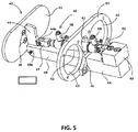
- FIG. 5 A detailed view of the support structure for the illustrative embodiment of the enclosure device 10 is shown In FIG. 5 .
- the plate frame 60 in the illustrative embodiment is formed with two casing apertures 62 therein.
- the casing apertures 62 are configured to accept one of the two casings 20, 30 previously described.
- a flange 34 on each casing 20, 30 abuts the respective casing aperture 62, and screws are used to affix the flange 34 to the plate frame.
- each casing 20, 30 may be secured to the plate frame 60 using any suitable structure and/or method, including but not limited to chemical adhesives, welding, rivets, pins, screws, and/or combinations thereof, and flanges 34 may not be necessary in other embodiments.
- An actuator aperture 61 may also be positioned in the plate frame 60, which is show oriented between the two casing apertures 62 in the Illustrative embodiment.
- a shutter mounting arm 68 may be affixed to one face of the plate frame 60, and an adaptor plate 66 may be affixed to the opposite face thereof using any suitable method and/or structure.
- the shutter mounting arm 68 is configured to extend out from the plate frame 60, and may be configured with a translator pivot 68a at the distal end of the shutter mounting arm 68.
- the translator pivot 68a Is simply configured as vertical groove into which the mounting arm connector 44c may fit, which is described in detail below.
- a rear block 64 may be affixed to the face of the adaptor plate 66 opposite the plate frame 60 using any method and/or structure suitable for the particular application of the enclosure device 10.
- An actuator mount 63 may be affixed to the top side of the rear block 64 as oriented in FIG. 5 using any method and/or structure suitable for the application.
- a translator 44 may be pivotally engaged with the shutter mounting arm 68 at the translator pivot 68a.
- this pivotal engagement is achieved through a tongue-and-groove arrangement, wherein the mounting arm connector 44c functions as the tongue, wherein a pin extends through the translator pivot 68a and the mounting arm connector 44c.
- the translator 44 may also be formed with a flap connector 44a.
- the flap connector 44a may be configured to pass through a flap slot 42a formed in the flap 42, as best shown in FIG. 6 .
- the translator 44 is secured to the flap 42 via two connector blocks 46 positioned on either side of the flap slot 42a and a connector pin 48 passing through an aperture in each connector block 46 and another aperture In the flap connector 44a. Accordingly, mechanical forces placed upon the translator 44 may be directly communicated to the flap 42.
- the connector blocks 46 are affixed to the flap 42 via a plurality of screws 16, but any suitable method and/or structure may be used without departing from the spirit and scope of the enclosure device 10. This arrangement allows the flap 42 to be replaced simply by removing the connector pin 48. Accordingly, as the flap 42 becomes damaged and/or worn due to use, it may be changed using minimal effort.
- the translator may be formed with an actuator connector 44b opposite the flap connector 44a, which is best shown in FIG. 6 .
- the actuator connector 44b is configured in a manner similar to that of the flap connector 44a and mounting arm connector 44c.
- the actuator connector 44b provides a pivotal connection point between the actuator 50 and the translator 44.
- the actuator connector 44b may be configured to fit within a groove formed on the actuator arm 54 to create a tongue- and-groove arrangement similar to that previously described for the mounting arm connector 44c and translator pivot 68a.
- the actuator body 52 may be secured to an actuator base 56, as shown in FIGS. 5 & 6 .
- the actuator base 56 may be secured to the actuator mount 63 described above.
- the actuator 50 may be configured such that the actuator body 52 passes through the actuator aperture 61 formed in the plate frame 60. If the actuator 50 is operated via pressurized fluid, as shown for the illustrative embodiment, one or more fluid ports 58 may be positioned on the actuator body 52. However, electrical actuators 50 will not require fluid ports 58.
- FIG. 1 shows the flap 42 In a first position, wherein the flap 42 is closed (i.e., positioned Immediately adjacent the camera lens 23 and light source lens 33). It is contemplated that the flap 42 will be so positioned when there is a high probability the work performed by the arm 12 may damage the camera lens 23 and/or light source lens 33.
- FIG. 2 shown the flap 42 in a second position, wherein the flap 42 is open (i.e., positioned away from the camera lens 23 and light source lens 33). It is contemplated that the flap 42 will be in the second position when there is a low probability that the work performed by the arm 12 may damage the camera lens 23 and/or light source lens 33.
- the inside surface of the flap 42 may be configured with one or more cushions and/or seals.
- the cushions and/or seals may be configured to provide a tighter seal between the portion of the casings 20, 30 adjacent the flap 42 and/or to protect the camera lens 23 and/or light source lens 33 during actuation of the flap 42 from the second position to the first position.
- the casings 20, 30 may be configured with cushions and/or seals adjacent the periphery of the camera lens 23 and/or light source lens 33 to fulfill a similar function.
- the enclosure device 10 includes two flaps 42, wherein a first flap 42 Is positioned adjacent the camera casing 20 and a second flap 42 is positioned the light source casing 30.
- Each flap 42 is operatively engaged with an actuator 50, such that either flap 42 may be actuated between a first and second position independently from the other flap 42.
- Such an embodiment may be configured in a manner similar to that shown for the illustrative embodiment of the enclosure device 10, wherein both actuators are parallel with the shutter mounting arm.
- the flap 42, translator 44, and connector blocks 46 are but one of an infinite number of shutter mechanisms 40, and variations and/or modifications of the illustrative embodiment of the enclosure device 10 will occur to those skilled in the art without departing from the spirit and scope thereof.
- the shutter mechanism 40 as disclosed protects both the camera lens 23 and light source lens 33 from damage due to molten weld spatter, sparks, debris, fumes, or other hazards. It also protects the camera lens 23 and light source lens 33 from discoloration and/or obscuring caused by welding fumes or other contaminants that may result from the work of the arm 12.
- the flap 42 may open to allow the camera 22 to record needed images and then close during work performed by the arm 12. This protection of the camera lens 23 during work of the arm 12 ensures the camera 22 captures an accurate image of consist quality, which is crucial for the arm 12 to function properly.
- mounting the camera casing 20 and light source casing 30 parallel with respect to one another with the actuator 50 positioned between the casings 20, 30 lends the enclosure device a lower profile.
- the enclosure device 10 may be positioned closer to the distal end of the arm 12 without concern that mobility of the arm will be decreased, as the arm 12 may still work in small spaces.
- the enclosure device 10 may be used with any arm 12, and is not limited by whether the arm 12 is robotic or otherwise. Additionally, the enclosure device 10 may be used with a robotic arm 12 that is manipulated by an operator in real-time, or one that is controlled by a preprogrammed computer or other control device to perform a certain function given certain input values and/or conditions.
- FIGS. 7-9 Another embodiment of an enclosure device in accordance with the present disclosure is shown in FIGS. 7-9 .
- the flap 42 may be generally rectangular shaped and the side plates 67 may be generally triangular shaped.
- One or more cross members 67a may extend from one side plate 67 to the other to add rigidity and strength to the enclosure device 10.
- a light source casing 30 may be sandwiched between two side plates 67 that are generally configured as mirror images of one another.
- the second embodiment of the enclosure device 10 may be configured specifically for a light source casing 30 housing a light source 32 configured as a laser designed to measure distances, but such a light source casing 30 and/or light source 32 In no way limits the scope of the enclosure device 10 as disclosed and claimed herein.
- an angled translator 44 may be pivotally mounted to the two side plates 67 via a plate connector 44d.
- the translator 44 may pivot with respect to the side plates 67 about a translator pivot 68a.
- An actuator connector 44b may be formed in the translator 44 adjacent the plate connector 44d.
- a flap connector 44a may be angled with respect to the actuator connector 44b and plate connector 44d to engage at least one connector block 46.
- One or more connector blocks 46 may be engaged with a flap 42 that covers a portion of the area between the two side plates 67 when in the closed position (as shown in FIGS. 7-9 ).
- a connector pin 48 may be used to engage the flap connector 44a and the connector blocks 46.
- an actuator 50 may be positioned within the enclosure device 10 to move the flap 42 between an open and a closed position.
- the actuator 50 may be pivotally mounted between the side plates 67 at the actuator base 56.
- the actuator arm 54 may pivotally engage the translator 44 at the actuator connector 44b. Accordingly, when the actuator arm 54 retracts into the actuator body 52, the translator 44 pivots causing the flap connector 44a to move upward from the vantage shown in FIGS. 7-9 , thereby opening the flap 42. Conversely, when the actuator arm 54 extends from the actuator body 52, the translator pivots in the opposite direction causing the flap connector 44a to move downward, thereby closing the flap 42.
- enclosure devices 10 may be used alone or in conjunction with other enclosure devices 10. Accordingly, the scope of the enclosure device 10 as disclosed and claim herein is in no way limited by the number of camera casings 20, cameras 22, light source casings 30, light sources 32, flaps 42, translators 44, actuators 50, or any other component of an enclosure device 10.
- the optimal dimensions and/or configuration of the camera casing 20, camera lens 23, sealing cap(s) 24 (if present), light source casing 30, light source lens 33, flange(s) 34 (if present), shutter mechanism 40, actuator 50, plate frame 60, actuator mount 63 (If present), rear block 64 (if present), adaptor plate 66 (if present), and shutter mounting arm 68 (If present) will vary from one embodiment of the enclosure device 10 to the next, and are therefore in no way limiting to the scope thereof.
- the various elements of the enclosure device 10 may be formed of any material that is suitable for the application for which the enclosure device 10 is used. Such materials include but are not limited to aluminum, metal, metallic alloys, aluminum alloys, polymers, other synthetic materials, and/or combinations thereof. However, it is contemplated that in the illustrative embodiment of the enclosure device 10, the various elements will be constructed of aluminum and/or an aluminum alloy that provides the proper balance of weight and structural integrity.
- enclosure device 10 is not limited to the specific embodiments pictured and described herein, but are intended to apply to all similar apparatuses for protecting a camera lens 23 and/or light source lens 33 at one time while not obscuring the line-of-sight therefore at another time. Modifications and alterations from the described embodiments will occur to those skilled in the art without departure from the scope of the enclosure device 10.
Landscapes
- Physics & Mathematics (AREA)
- General Physics & Mathematics (AREA)
- Engineering & Computer Science (AREA)
- Computer Networks & Wireless Communication (AREA)
- Radar, Positioning & Navigation (AREA)
- Remote Sensing (AREA)
- Optics & Photonics (AREA)
- Mechanical Engineering (AREA)
- Studio Devices (AREA)
- Blocking Light For Cameras (AREA)
- Accessories Of Cameras (AREA)
Abstract
Description
- CROSS REFERENCE TO RELATED APPLICATIONS: This application claims priority from and is a continuation of
U.S. Pat. App. No. 14/136,832 filed on December 20, 2013 U.S. Pat. App. No. 14/037,066 filed on September 25, 2013 (now US Patent #8,783,976 ), which claims priority from and is a continuation ofU.S. Pat App. No. 12/849,312 filed on August 3, 2010 8,571,398 ), which application claimed priority under 35 U.S.C. § 119(e) of provisionalU.S. Pat. App. Ser. No. 61/273,268 filed on August 3, 2009 U.S. Pat. App. No. 14/136,832 filed on December 20, 2013 U.S. Pat. App. Ser. No. 61/740,355 filed on December 20, 2012 - The present invention relates to an enclosure device according to the preamble of claim 1, for protecting Items positioned within the device, and more specifically, to an enclosure device for a camera and light source, wherein the enclosure device includes a shutter.
- In one embodiment of an enclosure device, a camera casing and light source casing are secured to a plate frame, and the enclosure device is configured to be mounted to an arm, such as a robotic welding arm. A shutter mounting arm may also be secured to the plate frame. A flap may be pivotally mounted to the distal end of the shutter mounting arm, such that the flap may be actuated between a first and second position by an actuator cooperatively engaged with the flap. The first position may be defined as to protect a camera lens positioned in the camera casing and a light source lens positioned In the light source casing. The second position may be defined as to not obscure a line-of-sight from either the light source and/or the camera to the work piece on the arm, A light source casing may be sandwiched between two side plates that are generally configured as mirror images of one another. The light source casing housing a light source may be configured as a laser designed to measure distances.
- In one embodiment, the invention provides an enclosure device configured to be attached to an arm, said enclosure device comprises a shutter mounting arm operatively engaged with a plate frame at a first end of the shutter mounting arm; a camera casing positioned in a first casing aperture of the plate frame; light source casIng positioned in a second casing aperture of the plate frame; a flap pivotally engaged with a second end of the shutter mounting arm; and a actuator configured to actuate the flap between a first and a second position wherein the first and second positions of said flap are substantially perpendicular to one another.
- Further embodiment and aspects of the invention are given in the claims, drawings and detailed description.
- In order that the advantages of the invention will be readily understood, a more particular description of the invention briefly described above will be rendered by reference to specific embodiments illustrated in the appended drawings. Understanding that these drawings depict only typical embodiments of the invention and are not therefore to be considered limited of its scope, the invention will be described and explained with additional specificity and detail through the use of the accompanying drawings.
-
FIG. 1 Is a perspective view of one embodiment of the enclosure device with the shutter closed. -
FIG. 2 is a perspective view of one embodiment of the enclosure device with the shutter open. -
FIG. 3A is a front plane view of one embodiment of the enclosure device with the shutter open. -
FIG. 3B is a rear plane view of one embodiment of the enclosure device. -
FIG. 4 is a perspective view of one embodiment of the enclosure device mounted to an arm, wherein the shutter is open. -
FIG. 5 is a perspective view of one embodiment of the enclosure device with the camera and light source casings and camera and light source removed for clarity. -
FIG. 6 is a detailed exploded view of one embodiment of the shutter mechanism. -
FIG. 7 is a perspective view of a second embodiment of the enclosure device with the shutter closed. -
FIG. 8 is a second perspective view of the second embodiment of the enclosure device with the shutter closed. -
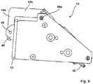
FIG. 9 is a side view of the second embodiment of the enclosure device with the shutter closed. - Before the various embodiments of the present invention are explained in detail, it is to be understood that the invention is not limited in its application to the details of construction and the arrangements of components set forth in the following description or illustrated in the drawings. The invention is capable of other embodiments and of being practiced or of being carried out in various ways. Also, it is to be understood that phraseology and terminology used herein with reference to device or element orientation (such as, for example, terms like "front", "back", "up", "down", "top", "bottom", and the like) are only used to simplify description of the present invention, and do not alone indicate or imply that the device or element referred to must have a particular orientation. In addition, terms such as "first", "second", and "third" are used herein and in the appended claims for purposes of description and are not intended to indicate or imply relative importance or significance.
- Referring now to the drawings, wherein like reference numerals designate identical or corresponding parts throughout the several views,
FIG. 1 provides a perspective view of one embodiment of anenclosure device 10 with theflap 42 in the closed position. Generally, theenclosure device 10 allows a user to protect a camera and/orcamera lens 23 from damage during welding or other operations performed by a work piece adjacent the distal end of anarm 12, which operations may be performed on any piece of material. One embodiment of theenclosure device 10 affixed to anarm 12 with aweld tip 14 thereon is shown inFIG. 4 . Although the illustrative embodiments of theenclosure device 10 are specifically adapted for use with welding, other embodiments may be adapted for sue witharms 12 performing other functions, including but not limited to drilling, boring, cutting, and/or combinations thereof. Accordingly, the scope of theenclosure device 10 is not limited by the type of work thearm 12 performs. Additionally, theenclosure device 10 may be mounted on structures other thanarms 12 without limitation. - As shown in
FIGS. 1 and2 , the illustrative embodiment of theenclosure device 10 includes acamera casing 20 and alight source casing 30, which are oriented parallel with respect to one another. Thecamera casing 20 andlight source casing 30 are configured to be parallel to provide theenclosure device 10 with a lower profile. In the illustrative embodiment, thecasings casings enclosure device 10. Eithercasing - A
camera lens 23 may be mounted in the end of thecamera casing 20 adjacent theflap 42. Alight source lens 33 may be mounted in the end of thelight source casing 30 adjacent theflap 42. Both thecamera lens 23 andlight source lens 33 may be transparent such that a camera 22 may be positioned in thecamera casing 20, and a light source 32 may be positioned in thelight source casing 30. Thelens - A sealing
cap 24 may be positioned on the end of eachcasing flap 42. The sealingcap 24 may be formed with a sealingcap aperture 24a therein. The sealing cap serves to hermetically seal the interior of thecasings cap aperture 24a provides an inlet/outlet for various conduits from the exterior environment to the interior of thecasings casings enclosure device 10 will require sealingcaps 24 havingsealing cap apertures 24a that hermetically seal the interior of thecasings - A detailed view of the support structure for the illustrative embodiment of the
enclosure device 10 is shown InFIG. 5 . As shown, theplate frame 60 in the illustrative embodiment is formed with twocasing apertures 62 therein. The casing apertures 62 are configured to accept one of the twocasings flange 34 on eachcasing respective casing aperture 62, and screws are used to affix theflange 34 to the plate frame. However, eachcasing plate frame 60 using any suitable structure and/or method, including but not limited to chemical adhesives, welding, rivets, pins, screws, and/or combinations thereof, andflanges 34 may not be necessary in other embodiments. Anactuator aperture 61 may also be positioned in theplate frame 60, which is show oriented between the twocasing apertures 62 in the Illustrative embodiment. - A
shutter mounting arm 68 may be affixed to one face of theplate frame 60, and anadaptor plate 66 may be affixed to the opposite face thereof using any suitable method and/or structure. Theshutter mounting arm 68 is configured to extend out from theplate frame 60, and may be configured with atranslator pivot 68a at the distal end of theshutter mounting arm 68. In the illustrative embodiment, thetranslator pivot 68a Is simply configured as vertical groove into which the mountingarm connector 44c may fit, which is described in detail below. Arear block 64 may be affixed to the face of theadaptor plate 66 opposite theplate frame 60 using any method and/or structure suitable for the particular application of theenclosure device 10. Anactuator mount 63 may be affixed to the top side of therear block 64 as oriented inFIG. 5 using any method and/or structure suitable for the application. - As best shown in
FIG. 6 , atranslator 44 may be pivotally engaged with theshutter mounting arm 68 at thetranslator pivot 68a. In the Illustrative embodiment of theenclosure device 10 this pivotal engagement is achieved through a tongue-and-groove arrangement, wherein the mountingarm connector 44c functions as the tongue, wherein a pin extends through thetranslator pivot 68a and the mountingarm connector 44c. - The
translator 44 may also be formed with aflap connector 44a. Theflap connector 44a may be configured to pass through aflap slot 42a formed in theflap 42, as best shown inFIG. 6 . In the illustrative embodiment, thetranslator 44 is secured to theflap 42 via twoconnector blocks 46 positioned on either side of theflap slot 42a and aconnector pin 48 passing through an aperture in eachconnector block 46 and another aperture In theflap connector 44a. Accordingly, mechanical forces placed upon thetranslator 44 may be directly communicated to theflap 42. In the illustrative embodiment, the connector blocks 46 are affixed to theflap 42 via a plurality ofscrews 16, but any suitable method and/or structure may be used without departing from the spirit and scope of theenclosure device 10. This arrangement allows theflap 42 to be replaced simply by removing theconnector pin 48. Accordingly, as theflap 42 becomes damaged and/or worn due to use, it may be changed using minimal effort. - The translator may be formed with an
actuator connector 44b opposite theflap connector 44a, which is best shown inFIG. 6 . Theactuator connector 44b is configured in a manner similar to that of theflap connector 44a and mountingarm connector 44c. Theactuator connector 44b provides a pivotal connection point between the actuator 50 and thetranslator 44. Theactuator connector 44b may be configured to fit within a groove formed on theactuator arm 54 to create a tongue- and-groove arrangement similar to that previously described for the mountingarm connector 44c andtranslator pivot 68a. - The
actuator body 52 may be secured to anactuator base 56, as shown inFIGS. 5 &6 . In turn, theactuator base 56 may be secured to theactuator mount 63 described above. Using anactuator base 56 simplifies the removal and/or replacement of theactuator 50, but other embodiments of theenclosure device 10 do not employ anactuator base 56. Theactuator 50 may be configured such that theactuator body 52 passes through theactuator aperture 61 formed in theplate frame 60. If theactuator 50 is operated via pressurized fluid, as shown for the illustrative embodiment, one or morefluid ports 58 may be positioned on theactuator body 52. However,electrical actuators 50 will not requirefluid ports 58. - As will be apparent in light of the preceding description and figures, the
actuator 50 causes theflap 42 to move between first and second positions.FIG. 1 shows theflap 42 In a first position, wherein theflap 42 is closed (i.e., positioned Immediately adjacent thecamera lens 23 and light source lens 33). It is contemplated that theflap 42 will be so positioned when there is a high probability the work performed by thearm 12 may damage thecamera lens 23 and/orlight source lens 33.FIG. 2 shown theflap 42 in a second position, wherein theflap 42 is open (i.e., positioned away from thecamera lens 23 and light source lens 33). It is contemplated that theflap 42 will be in the second position when there is a low probability that the work performed by thearm 12 may damage thecamera lens 23 and/orlight source lens 33. - The inside surface of the flap 42 (i.e., the surface that abuts the
camera lens 23 and/orlight source lens 33 when theflap 42 is closed) may be configured with one or more cushions and/or seals. The cushions and/or seals may be configured to provide a tighter seal between the portion of thecasings flap 42 and/or to protect thecamera lens 23 and/orlight source lens 33 during actuation of theflap 42 from the second position to the first position. Alternatively, thecasings camera lens 23 and/orlight source lens 33 to fulfill a similar function. - In another embodiment of the
enclosure device 10 not pictured herein, theenclosure device 10 includes twoflaps 42, wherein afirst flap 42 Is positioned adjacent thecamera casing 20 and asecond flap 42 is positioned thelight source casing 30. Eachflap 42 is operatively engaged with anactuator 50, such that eitherflap 42 may be actuated between a first and second position independently from theother flap 42. Such an embodiment may be configured in a manner similar to that shown for the illustrative embodiment of theenclosure device 10, wherein both actuators are parallel with the shutter mounting arm. Furthermore, theflap 42,translator 44, and connector blocks 46 are but one of an infinite number ofshutter mechanisms 40, and variations and/or modifications of the illustrative embodiment of theenclosure device 10 will occur to those skilled in the art without departing from the spirit and scope thereof. - The
shutter mechanism 40 as disclosed protects both thecamera lens 23 andlight source lens 33 from damage due to molten weld spatter, sparks, debris, fumes, or other hazards. It also protects thecamera lens 23 andlight source lens 33 from discoloration and/or obscuring caused by welding fumes or other contaminants that may result from the work of thearm 12. Theflap 42 may open to allow the camera 22 to record needed images and then close during work performed by thearm 12. This protection of thecamera lens 23 during work of thearm 12 ensures the camera 22 captures an accurate image of consist quality, which is crucial for thearm 12 to function properly. Furthermore, mounting thecamera casing 20 and light source casing 30 parallel with respect to one another with theactuator 50 positioned between thecasings enclosure device 10 may be positioned closer to the distal end of thearm 12 without concern that mobility of the arm will be decreased, as thearm 12 may still work in small spaces. Theenclosure device 10 may be used with anyarm 12, and is not limited by whether thearm 12 is robotic or otherwise. Additionally, theenclosure device 10 may be used with arobotic arm 12 that is manipulated by an operator in real-time, or one that is controlled by a preprogrammed computer or other control device to perform a certain function given certain input values and/or conditions. - Another embodiment of an enclosure device in accordance with the present disclosure Is shown in
FIGS. 7-9 . In this embodiment, theflap 42 may be generally rectangular shaped and theside plates 67 may be generally triangular shaped. One ormore cross members 67a may extend from oneside plate 67 to the other to add rigidity and strength to theenclosure device 10. A light source casing 30 may be sandwiched between twoside plates 67 that are generally configured as mirror images of one another. It is contemplated that the second embodiment of theenclosure device 10 may be configured specifically for a light source casing 30 housing a light source 32 configured as a laser designed to measure distances, but such a light source casing 30 and/or light source 32 In no way limits the scope of theenclosure device 10 as disclosed and claimed herein. - Generally, an
angled translator 44 may be pivotally mounted to the twoside plates 67 via aplate connector 44d. Thetranslator 44 may pivot with respect to theside plates 67 about atranslator pivot 68a. Anactuator connector 44b may be formed in thetranslator 44 adjacent theplate connector 44d. Aflap connector 44a may be angled with respect to theactuator connector 44b andplate connector 44d to engage at least oneconnector block 46. One or more connector blocks 46 may be engaged with aflap 42 that covers a portion of the area between the twoside plates 67 when in the closed position (as shown inFIGS. 7-9 ). Aconnector pin 48 may be used to engage theflap connector 44a and the connector blocks 46. - As with the previous embodiment, an
actuator 50 may be positioned within theenclosure device 10 to move theflap 42 between an open and a closed position. Theactuator 50 may be pivotally mounted between theside plates 67 at theactuator base 56. Theactuator arm 54 may pivotally engage thetranslator 44 at theactuator connector 44b. Accordingly, when theactuator arm 54 retracts into theactuator body 52, thetranslator 44 pivots causing theflap connector 44a to move upward from the vantage shown inFIGS. 7-9 , thereby opening theflap 42. Conversely, when theactuator arm 54 extends from theactuator body 52, the translator pivots in the opposite direction causing theflap connector 44a to move downward, thereby closing theflap 42. - One or more of the embodiments of
enclosure devices 10 disclosed herein may be used alone or in conjunction withother enclosure devices 10. Accordingly, the scope of theenclosure device 10 as disclosed and claim herein is in no way limited by the number ofcamera casings 20, cameras 22,light source casings 30, light sources 32, flaps 42,translators 44,actuators 50, or any other component of anenclosure device 10. - The optimal dimensions and/or configuration of the
camera casing 20,camera lens 23, sealing cap(s) 24 (if present), light source casing 30,light source lens 33, flange(s) 34 (if present),shutter mechanism 40,actuator 50,plate frame 60, actuator mount 63 (If present), rear block 64 (if present), adaptor plate 66 (if present), and shutter mounting arm 68 (If present) will vary from one embodiment of theenclosure device 10 to the next, and are therefore in no way limiting to the scope thereof. The various elements of theenclosure device 10 may be formed of any material that is suitable for the application for which theenclosure device 10 is used. Such materials include but are not limited to aluminum, metal, metallic alloys, aluminum alloys, polymers, other synthetic materials, and/or combinations thereof. However, it is contemplated that in the illustrative embodiment of theenclosure device 10, the various elements will be constructed of aluminum and/or an aluminum alloy that provides the proper balance of weight and structural integrity. - Having described the preferred embodiment, other features, advantages, and/or efficiencies of the
enclosure device 10 will undoubtedly occur to those versed in the art, as will numerous modifications and alterations of the disclosed embodiments and methods, all of which may be achieved without departing from the spirit and scope of theenclosure device 10. It should be noted that theenclosure device 10 is not limited to the specific embodiments pictured and described herein, but are intended to apply to all similar apparatuses for protecting acamera lens 23 and/orlight source lens 33 at one time while not obscuring the line-of-sight therefore at another time. Modifications and alterations from the described embodiments will occur to those skilled in the art without departure from the scope of theenclosure device 10.
| ELEMENT DESCRIPTION | Element No. |
| | 10 |
| | 12 |
| Weld | 14 |
| | 16 |
| | 20 |
| Camera | 22 |
| | 23 |
| | 24 |
| | 24a |
| | 30 |
| Light source | 32 |
| | 33 |
| | 34 |
| | 40 |
| | 42 |
| | 42a |
| | 44 |
| | |
| Actuator connector | |
| 44b | |
| | |
| Plate connector | |
| | |
| Connector block | |
| 46 | |
| | 48 |
| | 50 |
| | 52 |
| | 54 |
| | 56 |
| | 58 |
| | 60 |
| | 61 |
| | 62 |
| | 63 |
| Rear | 64 |
| | 66 |
| | 67 |
| Cross | 67a |
| Shutter | 68 |
| | 68a |
Claims (14)
- An enclosure device (10) configured to be attached to an arm (12), characterized in that said enclosure device (10) comprises:a) a shutter mounting arm (12) operatively engaged with a plate frame (60) at a first end of the shutter mounting arm (12);b) a camera casing (20) positioned in a first casing aperture (62) of the plate frame (60);c) a light source casing (30) positioned in a second casing aperture (62) of the plate frame (60);d) a flap (42) pivotally engaged with a second end of the shutter mounting arm (12); and,e) an actuator (50) configured to actuate the flap (42) between a first and a second position wherein the first and second positions of said flap are substantially perpendicular to one another.
- The enclosure device according to claim 1 wherein the enclosure device (10) further comprises a translator (44), wherein the translator (44) is pivotally secured to the shutter mounting arm (12), and wherein the translator (44) communicates mechanical forces from the retractable actuator (50) to the flap (42).
- The enclosure device according to claim 1 or 2 wherein a light source (32), such as a laser, is positioned in the second casing aperture of the plate frame for measurement of distances.
- The enclosure device according to one of the claims 1 to 3, wherein the actuator is retractable.
- The enclosure device according to one of the claims 1 to 4, wherein said first position is defined so that in said first position said flap (42) abuts said camera casing (20) and said light source casing (30), and wherein said second position is defined so that in said second position said flap (42) does not abut said camera casing (20) or said light source casing (30).
- The enclosure device according to one of the claims 1 to 5, wherein said camera casing (20) and said light source casing (30) are further defined as being parallel with respect to one another.
- The enclosure device according to one of the claims 1 to 6, wherein said enclosure device (10) further comprises at least one cross member (67a) extending from at least one side plate (67).
- The enclosure device according to one of the claims 1 to 7, wherein said enclosure device (10) further comprises at least one light source casing (30) positioned between a pair of side plates (67), wherein said side plates (67) are preferably generally configured as mirror images of one another.
- An enclosure device, in particular according to one of the claims 1 to 8, comprising:a) a plate frame (60) having an actuator aperture (61) and first and second casing apertures (62);b) a rear block (64) operatively engaged with said plate frame (60), wherein said rear block (64) is configured to couple said enclosure device (10) to an arm (12);c) an actuator (63) mount affixed to said rear block (64);d) a shutter mounting arm (12) operatively engaged with said plate frame (60) at a first end of said shutter mounting arm (12), wherein said shutter mounting arm (12) extends from said plate frame (60l in a direction opposite said rear bock (64);e) a camera casing (20) positioned in said first casing aperture (62) of said plate frame (60), wherein said camera casing (20) includes a camera lens at a first end of said camera casing and a sealing cap at a second end thereof;f) a light source casing (30) positioned in said second casing aperture (62) of said plate frame (60), wherein said light source casing (30) includes a light source lens (33) at a first end of said light source casing (30) and a sealing cap (24) at a second end thereof;g) a translator pivotally engaged with said shutter mounting arm (12) adjacent the distal end of said shutter mounting arm (12), wherein said translator includes a flap connector (44a) and an actuator connector (44d);h) a flap (42) substantially planar in orientation, wherein said flap (42) is engaged with said translator at said flap connector (44a); andi) an actuator (50) configured to actuate said flap (42) between a first and a second position, wherein said first and second positions are substantially perpendicular to one another.
- The enclosure device according to one of the claims 1 to 9, wherein said flap (42) is further defined as including a flap slot, wherein said flap connector (44a) passes through said flap slot, and wherein a plurality of connector blocks are engaged with said flap (42) on either side of said flap slot.
- The enclosure device according to one of the claims 1 to 10 wherein said actuator is further defined as passing through said actuator aperture in said frame plate (60).
- The enclosure device according to one of the claims 1 to 11, wherein said sealIng cap (24) on said camera casing (20) is further defined as including a sealing cap aperture, and wherein said sealing cap (24) on said light source casing (30) is further defined as Including a sealing cap aperture.
- The enclosure device according to one of the claims 1 to 13, wherein said camera casing (20) and said light source casing (30) are further defined as being parallel with respect to one another.
- The enclosure device according to one of the claims 1 to 13, wherein said camera casing (20) further comprises a first flange and wherein said light source casing (30) further comprises a second flange, wherein said camera casing (20) Is secured to said plate frame (60) about said first flange, and wherein said light source casing (30) is secured to said plate frame (60) about said second flange.
Applications Claiming Priority (7)
| Application Number | Priority Date | Filing Date | Title |
|---|---|---|---|
| US27326809P | 2009-08-03 | 2009-08-03 | |
| US12/849,312 US8571398B1 (en) | 2009-08-03 | 2010-08-03 | Enclosure device |
| US201261740355P | 2012-12-20 | 2012-12-20 | |
| US14/037,066 US8783976B1 (en) | 2009-08-03 | 2013-09-25 | Enclosure device |
| US14/136,832 US9389486B1 (en) | 2009-08-03 | 2013-12-20 | Enclosure device |
| US15/183,630 US9759986B2 (en) | 2009-08-03 | 2016-06-15 | Enclosure device |
| US15/455,661 US9785035B2 (en) | 2009-08-03 | 2017-03-10 | Enclosure device |
Publications (1)
| Publication Number | Publication Date |
|---|---|
| EP3258314A1 true EP3258314A1 (en) | 2017-12-20 |
Family
ID=56321000
Family Applications (1)
| Application Number | Title | Priority Date | Filing Date |
|---|---|---|---|
| EP17001008.6A Withdrawn EP3258314A1 (en) | 2009-08-03 | 2017-06-14 | Enclosure device |
Country Status (4)
| Country | Link |
|---|---|
| US (4) | US9389486B1 (en) |
| EP (1) | EP3258314A1 (en) |
| JP (1) | JP2018025753A (en) |
| CN (1) | CN107526230B (en) |
Families Citing this family (4)
| Publication number | Priority date | Publication date | Assignee | Title |
|---|---|---|---|---|
| US10262516B2 (en) * | 2016-06-01 | 2019-04-16 | Green Power Monitoring Systems, Inc. | Integrated hanger bearing monitor |
| CN107471064A (en) * | 2017-09-06 | 2017-12-15 | 湖南宇环智能装备有限公司 | It is a kind of to be automatically positioned calibration devices for motor stator base notch |
| CN110727161A (en) * | 2019-10-28 | 2020-01-24 | 宝钢工程技术集团有限公司 | Camera support |
| CN114839203A (en) * | 2022-04-29 | 2022-08-02 | 光阱(北京)科技有限公司 | Assembly supporting frame and glass curtain wall monitor |
Citations (5)
| Publication number | Priority date | Publication date | Assignee | Title |
|---|---|---|---|---|
| FR2564606A1 (en) * | 1984-05-19 | 1985-11-22 | Vinten Ltd | IMPROVEMENTS IN CLOSURE ARRANGEMENTS, IN PARTICULAR FOR AIR-TAKING APPARATUSES |
| US20040263666A1 (en) * | 2003-04-21 | 2004-12-30 | Kiyoaki Tsuji | Lens barrier mechanism and image pickup apparatus |
| US20130155238A1 (en) * | 2010-06-11 | 2013-06-20 | Huf Hulsbeck & Furst Gmbh & Co. Kg | Device Having A Camera Unit |
| US8571398B1 (en) * | 2009-08-03 | 2013-10-29 | Vizient, L.L.C. | Enclosure device |
| EP2743768A1 (en) * | 2012-12-14 | 2014-06-18 | CLAAS Tractor S.A.S. | Optical system for an agricultural machine |
Family Cites Families (32)
| Publication number | Priority date | Publication date | Assignee | Title |
|---|---|---|---|---|
| AT301331B (en) * | 1968-11-25 | 1972-08-25 | Eumig | Device for distance measurement |
| IT970289B (en) | 1972-06-02 | 1974-04-10 | Balda Werke Photographische | MINIMUM DIMENSIONS PHOTOGRAPHIC APPARATUS |
| US4492847A (en) | 1981-09-30 | 1985-01-08 | Unimation, Inc. | Manipulator welding apparatus with sensing arrangements for weld slam tracking |
| DE3480271D1 (en) | 1984-02-13 | 1989-11-30 | Boeing Co | Automatic traversing drilling unit and method of using |
| US4649426A (en) | 1984-06-12 | 1987-03-10 | The United States Of America As Represented By The United States Department Of Energy | Electronic imaging system and technique |
| JPS61279491A (en) | 1985-05-31 | 1986-12-10 | 株式会社安川電機 | Industrial robot with visual equipment |
| EP0275322B1 (en) | 1986-07-15 | 1993-07-07 | Kabushiki Kaisha Yaskawa Denki Seisakusho | Method of detecting position data in arc welding |
| FR2615966B1 (en) | 1987-06-01 | 1992-02-14 | Framatome Sa | DEVICE FOR TELEVISION MONITORING OF AN ARC WELDING OPERATION |
| US4918517A (en) | 1989-01-26 | 1990-04-17 | Westinghouse Electric Corp. | System and process for video monitoring a welding operation |
| US5255088A (en) | 1992-01-29 | 1993-10-19 | Arc Machines, Inc. | System and process for video monitoring a welding operation |
| US5520371A (en) | 1992-12-30 | 1996-05-28 | General Electric Company | Apparatus and method for viewing an industrial process such as a molten metal atomization process |
| US5391137A (en) | 1993-10-29 | 1995-02-21 | The Omega Company Inc. | Airbag folding apparatus and method |
| US6318951B1 (en) | 1999-07-09 | 2001-11-20 | Semitool, Inc. | Robots for microelectronic workpiece handling |
| US5694839A (en) | 1996-09-18 | 1997-12-09 | Trans Tech America, Inc. | Method and apparatus for pad printing cylindrical items |
| JPH10229518A (en) | 1997-02-13 | 1998-08-25 | Konica Corp | Electronic camera |
| JP2000102869A (en) * | 1998-09-30 | 2000-04-11 | Daihen Corp | Welding robot with sensor |
| JP3546422B2 (en) | 1999-02-23 | 2004-07-28 | 豊和工業株式会社 | Connection structure between base and drive unit and linear actuator |
| US6556245B1 (en) | 1999-03-08 | 2003-04-29 | Larry Allan Holmberg | Game hunting video camera |
| JP3543065B2 (en) | 1999-04-16 | 2004-07-14 | Smc株式会社 | Linear actuator |
| JP4146984B2 (en) | 2000-03-09 | 2008-09-10 | 富士フイルム株式会社 | Imaging device |
| JP3726699B2 (en) * | 2001-04-20 | 2005-12-14 | 日本ビクター株式会社 | Optical imaging device, optical distance measuring device |
| US20050107004A1 (en) | 2003-11-13 | 2005-05-19 | Brampton Brick Limited | Method and apparatus for removing flash from a brick |
| JP4393356B2 (en) * | 2004-11-22 | 2010-01-06 | キヤノン株式会社 | Camera case |
| US7412880B2 (en) * | 2005-11-23 | 2008-08-19 | Pioneer Hi-Bred International, Inc. | Device and method for screening a plant population for wind damage resistance traits |
| US7909551B2 (en) * | 2007-11-15 | 2011-03-22 | Southern Cross Cooperage Pty Ltd | Apparatus and method for shaving the inside of barrels |
| US8502866B2 (en) | 2008-03-14 | 2013-08-06 | Illinois Tool Works Inc. | Video recording device for a welder's helmet |
| WO2010041004A1 (en) * | 2008-10-09 | 2010-04-15 | Nauticam International Limited | Positioning devices |
| US8144193B2 (en) | 2009-02-09 | 2012-03-27 | Recognition Robotics, Inc. | Work piece tracking system and method |
| US20120075518A1 (en) * | 2010-09-29 | 2012-03-29 | Hoya Corporation | Imaging unit |
| US20120325781A1 (en) * | 2011-06-23 | 2012-12-27 | Deere & Company | Protective enclosure |
| TWM463365U (en) * | 2013-02-08 | 2013-10-11 | Qiu-Ming Lin | Paper camera and housing thereof |
| CN203561818U (en) * | 2013-10-21 | 2014-04-23 | 苏州恒远精密数控设备有限公司 | Waterproof industrial camera assembly |
-
2013
- 2013-12-20 US US14/136,832 patent/US9389486B1/en not_active Expired - Fee Related
-
2016
- 2016-06-15 US US15/183,630 patent/US9759986B2/en active Active
-
2017
- 2017-03-10 US US15/455,661 patent/US9785035B2/en active Active
- 2017-06-09 US US15/618,856 patent/US10139705B2/en active Active
- 2017-06-13 CN CN201710441702.7A patent/CN107526230B/en not_active Expired - Fee Related
- 2017-06-14 EP EP17001008.6A patent/EP3258314A1/en not_active Withdrawn
- 2017-06-14 JP JP2017116806A patent/JP2018025753A/en active Pending
Patent Citations (5)
| Publication number | Priority date | Publication date | Assignee | Title |
|---|---|---|---|---|
| FR2564606A1 (en) * | 1984-05-19 | 1985-11-22 | Vinten Ltd | IMPROVEMENTS IN CLOSURE ARRANGEMENTS, IN PARTICULAR FOR AIR-TAKING APPARATUSES |
| US20040263666A1 (en) * | 2003-04-21 | 2004-12-30 | Kiyoaki Tsuji | Lens barrier mechanism and image pickup apparatus |
| US8571398B1 (en) * | 2009-08-03 | 2013-10-29 | Vizient, L.L.C. | Enclosure device |
| US20130155238A1 (en) * | 2010-06-11 | 2013-06-20 | Huf Hulsbeck & Furst Gmbh & Co. Kg | Device Having A Camera Unit |
| EP2743768A1 (en) * | 2012-12-14 | 2014-06-18 | CLAAS Tractor S.A.S. | Optical system for an agricultural machine |
Also Published As
| Publication number | Publication date |
|---|---|
| US9389486B1 (en) | 2016-07-12 |
| US10139705B2 (en) | 2018-11-27 |
| US20160291444A1 (en) | 2016-10-06 |
| US9759986B2 (en) | 2017-09-12 |
| US20170343884A1 (en) | 2017-11-30 |
| US20170184943A1 (en) | 2017-06-29 |
| CN107526230A (en) | 2017-12-29 |
| US9785035B2 (en) | 2017-10-10 |
| CN107526230B (en) | 2021-05-11 |
| JP2018025753A (en) | 2018-02-15 |
Similar Documents
| Publication | Publication Date | Title |
|---|---|---|
| US8783976B1 (en) | Enclosure device | |
| US10139705B2 (en) | Enclosure device | |
| US20120325781A1 (en) | Protective enclosure | |
| EP3002080B1 (en) | Machine tool | |
| JP4600872B2 (en) | Industrial robot controller and its robot system | |
| CN107710068B (en) | Camera cover and imaging system provided with same | |
| CN107175534B (en) | Machine tool | |
| WO2006106258A3 (en) | Photographing device in particular for video surveillance and working methods of same | |
| CN101970982B (en) | Shape measuring device and robot device with the same | |
| EP4146431B1 (en) | Laser processing head and laser processing system including the same | |
| US6108072A (en) | Protection for optical sensors in industrial applications | |
| CN115629458A (en) | Dismounting device | |
| CN107390338B (en) | Lens assembly of light irradiation unit | |
| CN213754678U (en) | Working equipment | |
| JP7001884B2 (en) | Electronic device assembly equipment and electronic device assembly method | |
| JP4269207B2 (en) | Work machine with operation panel with protective cover | |
| CN209793797U (en) | Protection mechanism and manipulator | |
| EP1253817A3 (en) | Apparatus for picking and placing small objects | |
| CN116810247B (en) | Flat series shell limiting device and use method thereof | |
| JP2017040798A (en) | Finder device, imaging device | |
| CN223748843U (en) | A robotic arm camera protection bracket and welding robot | |
| CN112492187A (en) | Working equipment | |
| CN119111025A (en) | Positioning method of electric wire tool and electric wire construction device | |
| JP7113215B2 (en) | ELECTRONIC DEVICE ASSEMBLY DEVICE AND ELECTRONIC DEVICE ASSEMBLY METHOD | |
| CN121057639A (en) | robot |
Legal Events
| Date | Code | Title | Description |
|---|---|---|---|
| PUAI | Public reference made under article 153(3) epc to a published international application that has entered the european phase |
Free format text: ORIGINAL CODE: 0009012 |
|
| STAA | Information on the status of an ep patent application or granted ep patent |
Free format text: STATUS: THE APPLICATION HAS BEEN PUBLISHED |
|
| AK | Designated contracting states |
Kind code of ref document: A1 Designated state(s): AL AT BE BG CH CY CZ DE DK EE ES FI FR GB GR HR HU IE IS IT LI LT LU LV MC MK MT NL NO PL PT RO RS SE SI SK SM TR |
|
| AX | Request for extension of the european patent |
Extension state: BA ME |
|
| STAA | Information on the status of an ep patent application or granted ep patent |
Free format text: STATUS: REQUEST FOR EXAMINATION WAS MADE |
|
| 17P | Request for examination filed |
Effective date: 20180620 |
|
| RAX | Requested extension states of the european patent have changed |
Extension state: BA Payment date: 20180620 Extension state: ME Payment date: 20180620 |
|
| RBV | Designated contracting states (corrected) |
Designated state(s): AL AT BE BG CH CY CZ DE DK EE ES FI FR GB GR HR HU IE IS IT LI LT LU LV MC MK MT NL NO PL PT RO RS SE SI SK SM TR |
|
| STAA | Information on the status of an ep patent application or granted ep patent |
Free format text: STATUS: EXAMINATION IS IN PROGRESS |
|
| 17Q | First examination report despatched |
Effective date: 20200103 |
|
| STAA | Information on the status of an ep patent application or granted ep patent |
Free format text: STATUS: THE APPLICATION IS DEEMED TO BE WITHDRAWN |
|
| 18D | Application deemed to be withdrawn |
Effective date: 20200603 |