EP3258290B1 - Survey system - Google Patents
Survey system Download PDFInfo
- Publication number
- EP3258290B1 EP3258290B1 EP17175616.6A EP17175616A EP3258290B1 EP 3258290 B1 EP3258290 B1 EP 3258290B1 EP 17175616 A EP17175616 A EP 17175616A EP 3258290 B1 EP3258290 B1 EP 3258290B1
- Authority
- EP
- European Patent Office
- Prior art keywords
- section
- tracking
- target
- scanner
- optical axis
- Prior art date
- Legal status (The legal status is an assumption and is not a legal conclusion. Google has not performed a legal analysis and makes no representation as to the accuracy of the status listed.)
- Active
Links
- 230000003287 optical effect Effects 0.000 claims description 30
- 238000005259 measurement Methods 0.000 claims description 24
- 238000012986 modification Methods 0.000 description 8
- 230000004048 modification Effects 0.000 description 8
- 238000013461 design Methods 0.000 description 2
- 238000010586 diagram Methods 0.000 description 2
- 238000005070 sampling Methods 0.000 description 2
- 238000012790 confirmation Methods 0.000 description 1
- 238000001514 detection method Methods 0.000 description 1
- 230000000694 effects Effects 0.000 description 1
- 238000000034 method Methods 0.000 description 1
- 230000000007 visual effect Effects 0.000 description 1
Images


Classifications
-
- G—PHYSICS
- G01—MEASURING; TESTING
- G01C—MEASURING DISTANCES, LEVELS OR BEARINGS; SURVEYING; NAVIGATION; GYROSCOPIC INSTRUMENTS; PHOTOGRAMMETRY OR VIDEOGRAMMETRY
- G01C3/00—Measuring distances in line of sight; Optical rangefinders
- G01C3/02—Details
- G01C3/04—Adaptation of rangefinders for combination with telescopes or binoculars
-
- G—PHYSICS
- G01—MEASURING; TESTING
- G01C—MEASURING DISTANCES, LEVELS OR BEARINGS; SURVEYING; NAVIGATION; GYROSCOPIC INSTRUMENTS; PHOTOGRAMMETRY OR VIDEOGRAMMETRY
- G01C15/00—Surveying instruments or accessories not provided for in groups G01C1/00 - G01C13/00
- G01C15/002—Active optical surveying means
-
- G—PHYSICS
- G01—MEASURING; TESTING
- G01S—RADIO DIRECTION-FINDING; RADIO NAVIGATION; DETERMINING DISTANCE OR VELOCITY BY USE OF RADIO WAVES; LOCATING OR PRESENCE-DETECTING BY USE OF THE REFLECTION OR RERADIATION OF RADIO WAVES; ANALOGOUS ARRANGEMENTS USING OTHER WAVES
- G01S17/00—Systems using the reflection or reradiation of electromagnetic waves other than radio waves, e.g. lidar systems
- G01S17/02—Systems using the reflection of electromagnetic waves other than radio waves
- G01S17/06—Systems determining position data of a target
- G01S17/42—Simultaneous measurement of distance and other co-ordinates
-
- G—PHYSICS
- G01—MEASURING; TESTING
- G01S—RADIO DIRECTION-FINDING; RADIO NAVIGATION; DETERMINING DISTANCE OR VELOCITY BY USE OF RADIO WAVES; LOCATING OR PRESENCE-DETECTING BY USE OF THE REFLECTION OR RERADIATION OF RADIO WAVES; ANALOGOUS ARRANGEMENTS USING OTHER WAVES
- G01S17/00—Systems using the reflection or reradiation of electromagnetic waves other than radio waves, e.g. lidar systems
- G01S17/66—Tracking systems using electromagnetic waves other than radio waves
-
- G—PHYSICS
- G01—MEASURING; TESTING
- G01S—RADIO DIRECTION-FINDING; RADIO NAVIGATION; DETERMINING DISTANCE OR VELOCITY BY USE OF RADIO WAVES; LOCATING OR PRESENCE-DETECTING BY USE OF THE REFLECTION OR RERADIATION OF RADIO WAVES; ANALOGOUS ARRANGEMENTS USING OTHER WAVES
- G01S17/00—Systems using the reflection or reradiation of electromagnetic waves other than radio waves, e.g. lidar systems
- G01S17/87—Combinations of systems using electromagnetic waves other than radio waves
-
- G—PHYSICS
- G01—MEASURING; TESTING
- G01S—RADIO DIRECTION-FINDING; RADIO NAVIGATION; DETERMINING DISTANCE OR VELOCITY BY USE OF RADIO WAVES; LOCATING OR PRESENCE-DETECTING BY USE OF THE REFLECTION OR RERADIATION OF RADIO WAVES; ANALOGOUS ARRANGEMENTS USING OTHER WAVES
- G01S17/00—Systems using the reflection or reradiation of electromagnetic waves other than radio waves, e.g. lidar systems
- G01S17/88—Lidar systems specially adapted for specific applications
- G01S17/89—Lidar systems specially adapted for specific applications for mapping or imaging
Definitions
- the present invention relates to a survey system that acquires three-dimensional data of a survey site.
- Patent Literature 1 shows a surveying instrument having a tracking section and a laser pointer. The optical axis of the laser pointer beam is offset from an optical axis of the tracking light by a predetermined angle.
- An object of the present invention is to provide a survey system capable of acquiring point group data of a three-dimensional object desired to be measured without complicated setting.
- point group data of a three-dimensional object desired to be measured can be acquired without complicated setting.
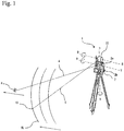
- Fig. 1 is an external perspective view of a survey system according to a first example.
- the reference sign 1 in Fig. 1 denotes a survey system according to the present example.
- the survey system 1 includes a surveying instrument 2 and a scanner 22 in appearance.
- the reference sign 9 denotes a prism as a target of the surveying instrument 2.
- Fig. 2 is a control block diagram of the survey system 1.
- the survey system 1 includes a horizontal angle detector 11, a vertical angle detector 12, a horizontal rotation driving section 13, a vertical rotation driving section 14, a display section 15, an operation section 16, an arithmetic control section 17, a tracking light transmitting section 18, a tracking light receiving section 19, a measurement section 20, a storage section 21, and a scanner 22.
- the horizontal angle detector 11, the vertical angle detector 12, the horizontal rotation driving section 13, the vertical rotation driving section 14, the arithmetic control section 17, and the storage section 21 are housed in a bracket portion 2b (described below) of the surveying instrument 2, and the display section 15 and the operation section 16 are provided outside the bracket portion 2b.
- the tracking light transmitting section 18, the tracking light receiving section 19, and the measurement section 20 are housed in a telescope 2a (described below) of the surveying instrument 2.
- the scanner 22 is fixed to the telescope 2a so as to be disposed as described below.
- the surveying instrument 2 is a so-called motor drive total station, and installed at a known point by using a tripod.
- the surveying instrument 2 includes, in order from the lower side, a leveling section, a base portion provided on the leveling section, the bracket portion 2b that rotates around a horizontal rotary shaft H-H on the base portion, and the telescope 2a that rotates around a vertical rotary shaft V-V at the center of the bracket portion 2b.
- the horizontal rotation driving section 13 and the vertical rotation driving section 14 are motors, and are controlled by the arithmetic control section 17 and respectively drive the horizontal rotary shaft H-H and the vertical rotary shaft V-V.
- the arithmetic control section 17 In the surveying instrument 2, by collaboration of horizontal rotation of the bracket portion 2b and vertical rotation of the telescope 2a, distance measuring light or tracking light is emitted from the telescope 2a.
- the display section 15 and the operation section 16 are interfaces of the survey system 1, and by these sections, commanding and setting of a survey operation and confirmation of operation status and measurement results can be performed.
- Each of the horizontal angle detector 11 and the vertical angle detector 12 is an absolute encoder or an incremental encoder including a rotary disk, a slit, a light emitting diode, and an image sensor.
- the horizontal angle detector 11 is provided with respect to the horizontal rotary shaft H-H and detects a rotation angle in the horizontal direction of the bracket portion 2b.
- the vertical angle detector 12 is provided with respect to the vertical rotary shaft V-V and detects a rotation angle in the vertical direction of the telescope 2a.
- the tracking light transmitting section 18 emits, as tracking light, an infrared laser, etc., with a wavelength different from that of distance measuring light.
- the reference sign 4 in Fig. 1 denotes an optical axis of tracking light. The design is made so that the optical axis 4 of the tracking light is on the horizontal rotary shaft H-H of the surveying instrument 2.
- the tracking light receiving section 19 is an image sensor, for example, a CCD sensor or a CMOS sensor.
- the tracking light receiving section 19 acquires a landscape image including the tracking light and a landscape image excluding the tracking light. Both of these images are transmitted to the arithmetic control section 17.
- a center of a target image is obtained from a difference between the both of these images, a position at which a deviation of the center of the target image from a center of a visual axis of the telescope 2a falls within a predetermined value is detected as a position of the target, and tracking is automatically performed so that the telescope 2a always faces a direction of the target.
- the tracking light transmitting section 18, the tracking light receiving section 19, and the arithmetic control section 17 are "tracking section.”
- the measurement section 20 includes a distance measuring light transmitting section and a distance measuring light receiving section, and emits a distance measuring light, for example, an infrared laser, etc., to a target and receives a light reflected on the target. Then, similarly to the tracking section, the measurement section 20 captures the target from a difference between an image including the distance measuring light and an image excluding the distance measuring light, and after collimating is completed, performs distance measuring and angle measuring to the target.
- a distance measuring light transmitting section and a distance measuring light receiving section and emits a distance measuring light, for example, an infrared laser, etc.
- the scanner 22 is a so-called uniaxial laser scanner, and the reference sign 5 denotes an optical axis of the scanner 22 at a certain time, and the reference sign 10 denotes an irradiation point (measurement position) at this time.
- the scanner 22 irradiates a pulsed laser around a rotary shaft R-R as a single axis, detects reflected light of the pulsed laser, and performs distance measuring and angle measuring for each pulsed laser beam to acquire point group data.
- the arithmetic control section 17 is a microcontroller including, for example, a CPU, a ROM, and a RAM, etc., mounted on an integrated circuit, and performs control of the rotation driving sections 13 and 14 and light emission control of the measurement section 20 and the tracking section, performs automatic tracking, automatic collimating, and distance measuring and angle measuring of a target, and acquires survey data.
- the arithmetic control section 17 performs rotation control and light emission control of the scanner 22, and acquires point group data of the irradiation point 10.
- the storage section 21 is, for example, a hard disk drive, saves programs for the arithmetic control described above, and stores acquired survey data and point group data.
- the survey system 1 has the above-described elements, and the following disposition.
- the scanner 22 is disposed so that the rotary shaft R-R extends in the horizontal direction and a scanning line SL in the vertical direction is obtained.
- the scanner 22 is fixed to an upper portion of the telescope 2a so that an optical axis 5 of the scanner is on the horizontal rotary shaft H-H of the surveying instrument 2, and the optical axis 5 of the scanner is offset by a fixed angle ⁇ in the horizontal direction from the optical axis 4 of the tracking light.
- the fixed angle ⁇ is an angle at which the scanner 22 does not scan the prism 9, and is preferably set to a minimum value.
- point group data can be acquired as follows.
- a tracking program is executed. Thereafter, a survey program using the scanner 22 is also started. Then, the telescope 2a is controlled so as to always face the prism 9 by automatic tracking.
- the scanner 22 fixed to the telescope 2a also faces the prism 9 similarly to the telescope 2a, however, the optical axis 5 of the scanner is offset by the fixed angle ⁇ in the horizontal direction from the optical axis 4 of the tracking light, so that the scanning line SL does not match the prism 9, and is always controlled around the prism 9 (at a position at a distance from the prism 9).
- a three-dimensional position of the irradiation point 10 in a coordinate system of the surveying instrument 2 can be calculated from a rotation angle obtained by the horizontal angle detector 11 and the vertical angle detector 12 of the surveying instrument 2 and a measured distance value obtained by the scanner 22.
- the scanning line SL can be moved in accordance with movement of the prism 9. That is, the scanning line SL can be controlled around the target, so that even without setting a measurement area, data of a measuring object and the surrounding thereof can be acquired.
- the following usage is also possible.
- the survey system 1 when it is desired to acquire point group data of a certain location, by reciprocating the target in this location, automatic tracking is performed, and even without setting a measurement area, point group data of the location can be acquired. That is, by moving the target at a location desired to be measured, a measurement area can be actively determined. At this time, by displaying the acquired point group data in real time on the display section 15 or a personal computer, etc., connected by wire or wirelessly, a survey can be performed while a scanning density is confirmed on the spot.
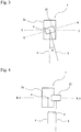
- Fig. 4 is a plan view of a survey system 1 according to an embodiment.
- the same elements as in the first example are designated by the same reference signs and description thereof is omitted.
- the optical axis 5 of the scanner and the optical axis 4 of tracking light are parallel to each other, and the optical axis 5 of the scanner is not on the horizontal rotary shaft H-H of the surveying instrument 2.
- the scanner 22 is fixed to an upper portion of the telescope 2a so that the optical axis 5 of the scanner is offset by a distance d in the horizontal direction from the optical axis 4 of the tracking light.
- the scanner 22 is fixed to a position offset in the horizontal direction with respect to the telescope 2a (tracking section), therefore, the scanning line SL does not match the prism 9, and is always controlled around the prism 9 (controlled at a position at a distance from the prism 9). Since the value of the offset distance d is known in advance, a three-dimensional position of the irradiation point 10 in a coordinate system of the surveying instrument 2 can be calculated from a rotation angle obtained by the horizontal angle detector 11 and the vertical angle detector 12 of the surveying instrument 2 and a measured distance value obtained by the scanner 22. Therefore, as in the case of the first example, even without setting a measurement area, data of a measuring object and the surrounding thereof can be acquired, and by moving the target in a location desired to be measured, a measurement area can be actively determined.
- the position to which the scanner 22 is fixed is not limited to the position shown in the drawing, and may be any position or distance as long as the optical axis 5 of the scanner is offset in the horizontal direction from the optical axis 4 of the tracking light.
- the position to which the scanner is fixed may be a lower portion or a side portion of the telescope 2a, or a lower portion of the main body of the surveying instrument 2 (for example, lower portion of the display section 15) as long as the design of the surveying instrument 2 allows.
- the optical axis 5 of the scanner is on the horizontal rotary shaft H-H of the surveying instrument 2 as shown in Fig. 3 , and the fixed angle ⁇ is an arbitrary angle including 0.
- the same elements as in the first example are designated by the same reference signs, and description thereof is omitted.
- Fig. 5 is a view of an image acquired by a survey system 1 according to the third example.
- Fig. 5 shows an image acquired by the tracking light receiving section 19, and a reference sign 8 denotes an image of reflected light of tracking light.
- Different wavelengths are adopted for the scanner light and the tracking light, so that an image of the scanner is not projected on the tracking light receiving section 19. Therefore, in Fig. 5 , scanner light is imaginarily shown as a scanning line SL although the scanner light is not projected in actuality.
- the reference sign O denotes an image center of the tracking light receiving section 19.
- control is performed so that the image 8 of reflected light of the tracking light is projected on a position S at a predetermined distance in the horizontal direction from the scanning line SL.
- a position at which the image 8 (center of the target image) of the reflected light of the tracking light falls within a predetermined value from the position S is detected as a target position, and tracking is performed. Then, according to a distance to the target, the position S of the tracking light receiving section 19 is varied, and by arbitrarily changing an angle ⁇ 3 between the optical axis 4 of the tracking light and the optical axis 5 of the scanner in actuality, the above-mentioned distance between the target (prism 9) and the irradiation point 10 in actuality can be always offset by a fixed distance D.
- the distance to the target can be obtained by, for example, a method in which (1) tracking is performed at the position of the image center O at the start of tracking, distance measuring is performed by the measurement section 20, a tracking position (position S) is determined according to an acquired value, and thereafter, the position S is not changed, (2) the image center O is tracked at the start of tracking, distance measuring is performed by the measurement section 20, and then, after the tracking position (position S) is changed, a size of the prism image according to the distance is measured to obtain the distance, and (3) the tracking position is sometimes returned to the image center O and distance measuring is performed during tracking.
- the dashed line in Fig. 5 is a line obtained by projecting the optical axis 5 of the scanner on the same plane as the optical axis 4 of the tracking light.
- the scanning line SL can always be controlled to a position offset by the fixed distance D with respect to the prism 9. Therefore, as in the case of the first embodiment, even without setting a measurement area, data of a measuring object and the surrounding thereof can be acquired, and by moving the target in a location desired to be measured, a measurement area can be actively determined.
- the tracking position is required to be separated at least in the horizontal direction and may be displaced in the vertical direction. That is, the tracking position on the tracking image sensor may be offset by a fixed angle from the detection position of the scanner.
- the surveying instrument 2 being a total station can measure an elevation angle of the prism 9 from a measured distance value and a measured angle value of the prism 9. Therefore, in a survey system 1 of Modification 1, point group data of other than an area extended by a predetermined angle upward and downward in the vertical direction around the elevation angle of the prism 9 is not saved in the storage section 21.
- Fig. 6 is a view describing Modification 1.
- the arrows in Fig. 6 show movements of the scanning line SL in accordance with movements of the prism 9.
- a reference sign 31 denotes a horizontal line of a position corresponding to the elevation angle of the prism 9, and the reference signs 32 denote horizontal lines extended by ⁇ (several to several tens of degrees) in the vertical direction from a horizontal line 31.
- the reference sign ⁇ that defines a range in the vertical direction of the measurement area may be an angle as described above, or may be set as a length, for example, ⁇ 1 m. In the case that ⁇ is set as a length, setting may be made so that the angle is automatically determined according to the distance.
- a laser beam of the scanner 22 may be invisible light or visible light, and in the case of invisible light, there is a problem that an operator cannot identify the irradiation point 10. Therefore, a visible light line laser having an optical axis matching the optical axis 5 of the scanner in the horizontal direction is also preferably provided on, for example, a lower portion of the main body of the surveying instrument 2, so as to emit light as guide light. Accordingly, an operator can clearly identify the scanning direction.
- the scanner 22 is scanned in the vertical direction, however, when a sampling position is fixed, even by repeating reciprocating scanning, there is a possibility that only point group data at positions at which the vertical angle is the same can be obtained. Therefore, it is also preferable to shift the scanning start point in increments of a minute angle. For example, at the time of turning back of reciprocating movement, by randomly delaying a laser beam emission timing of the scanner 22 or regularly delaying the timing in increments of, for example, 0.5 seconds, the sampling position (vertical angle) of scanning differs between upward scanning and downward scanning, so that more accurate and fine point group data can be obtained.
Description
- The present invention relates to a survey system that acquires three-dimensional data of a survey site.
- In recent years, a three-dimensional survey of a three-dimensional object is frequently conducted, and demand for images with three-dimensional data of a three-dimensional object has increased. Therefore, at a survey site, by using a laser scanner, a pulsed laser is scanned on a predetermined measurement area and distance measuring is performed for three-dimensional position data of an irradiation point of the pulsed laser to acquire point group data of the measurement area (for example, refer to Patent Literature 1).
Patent Literature 2 shows a surveying instrument having a tracking section and a laser pointer. The optical axis of the laser pointer beam is offset from an optical axis of the tracking light by a predetermined angle. -
- Patent Literature 1:
Japanese Patent No. 5057734 - Patent Literature 2:
European patent application No. 2889576 A1 - However, with a conventional laser scanner, in order to sufficiently obtain point group data of a three-dimensional object desired to be measured, it is necessary to preferably set a measurement area, and in particular, when it is desired to obtain detailed point group data, more accurate setting is necessary.
- An object of the present invention is to provide a survey system capable of acquiring point group data of a three-dimensional object desired to be measured without complicated setting.
- In order to solve the above-described problem a survey system defined by
claim 1 is provided. - With the survey system according to the present invention, point group data of a three-dimensional object desired to be measured can be acquired without complicated setting.
-
-
Fig. 1 is an external perspective view of a survey system according to a first example not forming part of the invention. -
Fig. 2 is a block diagram of a configuration of the survey system according to the first example. -
Fig. 3 is a plan view of the survey system according to the first example. -
Fig. 4 is a plan view of a survey system according to an embodiment. -
Fig. 5 is an external perspective view of a survey system according to a third example not forming part of the invention, together with an image drawing acquired by the survey system. -
Fig. 6 is a view describing amodification 1 of the embodiment and examples described above. - Next, a preferred embodiment of the present invention and examples are described with reference to the drawings.
-
Fig. 1 is an external perspective view of a survey system according to a first example. Thereference sign 1 inFig. 1 denotes a survey system according to the present example. Thesurvey system 1 includes asurveying instrument 2 and ascanner 22 in appearance. Thereference sign 9 denotes a prism as a target of thesurveying instrument 2. -
Fig. 2 is a control block diagram of thesurvey system 1. Thesurvey system 1 includes ahorizontal angle detector 11, avertical angle detector 12, a horizontalrotation driving section 13, a verticalrotation driving section 14, adisplay section 15, anoperation section 16, anarithmetic control section 17, a trackinglight transmitting section 18, a trackinglight receiving section 19, ameasurement section 20, astorage section 21, and ascanner 22. - The
horizontal angle detector 11, thevertical angle detector 12, the horizontalrotation driving section 13, the verticalrotation driving section 14, thearithmetic control section 17, and thestorage section 21 are housed in abracket portion 2b (described below) of thesurveying instrument 2, and thedisplay section 15 and theoperation section 16 are provided outside thebracket portion 2b. The trackinglight transmitting section 18, the trackinglight receiving section 19, and themeasurement section 20 are housed in atelescope 2a (described below) of thesurveying instrument 2. Thescanner 22 is fixed to thetelescope 2a so as to be disposed as described below. - The
surveying instrument 2 is a so-called motor drive total station, and installed at a known point by using a tripod. Thesurveying instrument 2 includes, in order from the lower side, a leveling section, a base portion provided on the leveling section, thebracket portion 2b that rotates around a horizontal rotary shaft H-H on the base portion, and thetelescope 2a that rotates around a vertical rotary shaft V-V at the center of thebracket portion 2b. - The horizontal
rotation driving section 13 and the verticalrotation driving section 14 are motors, and are controlled by thearithmetic control section 17 and respectively drive the horizontal rotary shaft H-H and the vertical rotary shaft V-V. In thesurveying instrument 2, by collaboration of horizontal rotation of thebracket portion 2b and vertical rotation of thetelescope 2a, distance measuring light or tracking light is emitted from thetelescope 2a. - The
display section 15 and theoperation section 16 are interfaces of thesurvey system 1, and by these sections, commanding and setting of a survey operation and confirmation of operation status and measurement results can be performed. - Each of the
horizontal angle detector 11 and thevertical angle detector 12 is an absolute encoder or an incremental encoder including a rotary disk, a slit, a light emitting diode, and an image sensor. Thehorizontal angle detector 11 is provided with respect to the horizontal rotary shaft H-H and detects a rotation angle in the horizontal direction of thebracket portion 2b. Thevertical angle detector 12 is provided with respect to the vertical rotary shaft V-V and detects a rotation angle in the vertical direction of thetelescope 2a. - The tracking
light transmitting section 18 emits, as tracking light, an infrared laser, etc., with a wavelength different from that of distance measuring light. Thereference sign 4 inFig. 1 denotes an optical axis of tracking light. The design is made so that theoptical axis 4 of the tracking light is on the horizontal rotary shaft H-H of thesurveying instrument 2. The trackinglight receiving section 19 is an image sensor, for example, a CCD sensor or a CMOS sensor. The trackinglight receiving section 19 acquires a landscape image including the tracking light and a landscape image excluding the tracking light. Both of these images are transmitted to thearithmetic control section 17. In thearithmetic control section 17, a center of a target image is obtained from a difference between the both of these images, a position at which a deviation of the center of the target image from a center of a visual axis of thetelescope 2a falls within a predetermined value is detected as a position of the target, and tracking is automatically performed so that thetelescope 2a always faces a direction of the target. The trackinglight transmitting section 18, the trackinglight receiving section 19, and thearithmetic control section 17 are "tracking section." - The
measurement section 20 includes a distance measuring light transmitting section and a distance measuring light receiving section, and emits a distance measuring light, for example, an infrared laser, etc., to a target and receives a light reflected on the target. Then, similarly to the tracking section, themeasurement section 20 captures the target from a difference between an image including the distance measuring light and an image excluding the distance measuring light, and after collimating is completed, performs distance measuring and angle measuring to the target. - The
scanner 22 is a so-called uniaxial laser scanner, and thereference sign 5 denotes an optical axis of thescanner 22 at a certain time, and thereference sign 10 denotes an irradiation point (measurement position) at this time. Thescanner 22 irradiates a pulsed laser around a rotary shaft R-R as a single axis, detects reflected light of the pulsed laser, and performs distance measuring and angle measuring for each pulsed laser beam to acquire point group data. - The
arithmetic control section 17 is a microcontroller including, for example, a CPU, a ROM, and a RAM, etc., mounted on an integrated circuit, and performs control of therotation driving sections measurement section 20 and the tracking section, performs automatic tracking, automatic collimating, and distance measuring and angle measuring of a target, and acquires survey data. In addition, thearithmetic control section 17 performs rotation control and light emission control of thescanner 22, and acquires point group data of theirradiation point 10. Thestorage section 21 is, for example, a hard disk drive, saves programs for the arithmetic control described above, and stores acquired survey data and point group data. - The
survey system 1 has the above-described elements, and the following disposition. In thesurvey system 1, as shown inFig. 1 , thescanner 22 is disposed so that the rotary shaft R-R extends in the horizontal direction and a scanning line SL in the vertical direction is obtained. Further, as shown inFig. 3 as a plan view of thesurvey system 1, thescanner 22 is fixed to an upper portion of thetelescope 2a so that anoptical axis 5 of the scanner is on the horizontal rotary shaft H-H of thesurveying instrument 2, and theoptical axis 5 of the scanner is offset by a fixed angle θ in the horizontal direction from theoptical axis 4 of the tracking light. The fixed angle θ is an angle at which thescanner 22 does not scan theprism 9, and is preferably set to a minimum value. - By using the
survey system 1 described above, point group data can be acquired as follows. - First, with the
survey system 1, a tracking program is executed. Thereafter, a survey program using thescanner 22 is also started. Then, thetelescope 2a is controlled so as to always face theprism 9 by automatic tracking. Thescanner 22 fixed to thetelescope 2a also faces theprism 9 similarly to thetelescope 2a, however, theoptical axis 5 of the scanner is offset by the fixed angle θ in the horizontal direction from theoptical axis 4 of the tracking light, so that the scanning line SL does not match theprism 9, and is always controlled around the prism 9 (at a position at a distance from the prism 9). (The arrow inFig. 1 shows movement of the scanning line SL along with movement of theprism 9.) Since the value of the fixed angle θ is known in advance, a three-dimensional position of theirradiation point 10 in a coordinate system of the surveyinginstrument 2 can be calculated from a rotation angle obtained by thehorizontal angle detector 11 and thevertical angle detector 12 of the surveyinginstrument 2 and a measured distance value obtained by thescanner 22. - As described above, by using the
survey system 1, without scanning theprism 9, the scanning line SL can be moved in accordance with movement of theprism 9. That is, the scanning line SL can be controlled around the target, so that even without setting a measurement area, data of a measuring object and the surrounding thereof can be acquired. - In addition, the following usage is also possible. By using the
survey system 1, when it is desired to acquire point group data of a certain location, by reciprocating the target in this location, automatic tracking is performed, and even without setting a measurement area, point group data of the location can be acquired. That is, by moving the target at a location desired to be measured, a measurement area can be actively determined. At this time, by displaying the acquired point group data in real time on thedisplay section 15 or a personal computer, etc., connected by wire or wirelessly, a survey can be performed while a scanning density is confirmed on the spot. -
Fig. 4 is a plan view of asurvey system 1 according to an embodiment. The same elements as in the first example are designated by the same reference signs and description thereof is omitted. In the embodiment, theoptical axis 5 of the scanner and theoptical axis 4 of tracking light are parallel to each other, and theoptical axis 5 of the scanner is not on the horizontal rotary shaft H-H of the surveyinginstrument 2. Instead, thescanner 22 is fixed to an upper portion of thetelescope 2a so that theoptical axis 5 of the scanner is offset by a distance d in the horizontal direction from theoptical axis 4 of the tracking light. - In the embodiment, the
scanner 22 is fixed to a position offset in the horizontal direction with respect to thetelescope 2a (tracking section), therefore, the scanning line SL does not match theprism 9, and is always controlled around the prism 9 (controlled at a position at a distance from the prism 9). Since the value of the offset distance d is known in advance, a three-dimensional position of theirradiation point 10 in a coordinate system of the surveyinginstrument 2 can be calculated from a rotation angle obtained by thehorizontal angle detector 11 and thevertical angle detector 12 of the surveyinginstrument 2 and a measured distance value obtained by thescanner 22. Therefore, as in the case of the first example, even without setting a measurement area, data of a measuring object and the surrounding thereof can be acquired, and by moving the target in a location desired to be measured, a measurement area can be actively determined. - The position to which the
scanner 22 is fixed is not limited to the position shown in the drawing, and may be any position or distance as long as theoptical axis 5 of the scanner is offset in the horizontal direction from theoptical axis 4 of the tracking light. The position to which the scanner is fixed may be a lower portion or a side portion of thetelescope 2a, or a lower portion of the main body of the surveying instrument 2 (for example, lower portion of the display section 15) as long as the design of the surveyinginstrument 2 allows. - In a third example, the
optical axis 5 of the scanner is on the horizontal rotary shaft H-H of the surveyinginstrument 2 as shown inFig. 3 , and the fixed angle θ is an arbitrary angle including 0. The same elements as in the first example are designated by the same reference signs, and description thereof is omitted. -
Fig. 5 is a view of an image acquired by asurvey system 1 according to the third example.Fig. 5 shows an image acquired by the trackinglight receiving section 19, and a reference sign 8 denotes an image of reflected light of tracking light. Different wavelengths are adopted for the scanner light and the tracking light, so that an image of the scanner is not projected on the trackinglight receiving section 19. Therefore, inFig. 5 , scanner light is imaginarily shown as a scanning line SL although the scanner light is not projected in actuality. The reference sign O denotes an image center of the trackinglight receiving section 19. In the third embodiment, control is performed so that the image 8 of reflected light of the tracking light is projected on a position S at a predetermined distance in the horizontal direction from the scanning line SL. - That is, in the third example, a position at which the image 8 (center of the target image) of the reflected light of the tracking light falls within a predetermined value from the position S is detected as a target position, and tracking is performed. Then, according to a distance to the target, the position S of the tracking
light receiving section 19 is varied, and by arbitrarily changing an angle θ3 between theoptical axis 4 of the tracking light and theoptical axis 5 of the scanner in actuality, the above-mentioned distance between the target (prism 9) and theirradiation point 10 in actuality can be always offset by a fixed distance D. The distance to the target can be obtained by, for example, a method in which (1) tracking is performed at the position of the image center O at the start of tracking, distance measuring is performed by themeasurement section 20, a tracking position (position S) is determined according to an acquired value, and thereafter, the position S is not changed, (2) the image center O is tracked at the start of tracking, distance measuring is performed by themeasurement section 20, and then, after the tracking position (position S) is changed, a size of the prism image according to the distance is measured to obtain the distance, and (3) the tracking position is sometimes returned to the image center O and distance measuring is performed during tracking. The dashed line inFig. 5 is a line obtained by projecting theoptical axis 5 of the scanner on the same plane as theoptical axis 4 of the tracking light. Thus, even by displacing the tracking position on the tracking image sensor in the horizontal direction, the scanning line SL can always be controlled to a position offset by the fixed distance D with respect to theprism 9. Therefore, as in the case of the first embodiment, even without setting a measurement area, data of a measuring object and the surrounding thereof can be acquired, and by moving the target in a location desired to be measured, a measurement area can be actively determined. The tracking position is required to be separated at least in the horizontal direction and may be displaced in the vertical direction. That is, the tracking position on the tracking image sensor may be offset by a fixed angle from the detection position of the scanner. - Preferred modifications of the embodiment and examples described above are described. The same elements as in the embodiments are designated by the same reference signs, and description thereof is omitted.
- The surveying
instrument 2 being a total station can measure an elevation angle of theprism 9 from a measured distance value and a measured angle value of theprism 9. Therefore, in asurvey system 1 ofModification 1, point group data of other than an area extended by a predetermined angle upward and downward in the vertical direction around the elevation angle of theprism 9 is not saved in thestorage section 21.Fig. 6 is aview describing Modification 1. The arrows inFig. 6 show movements of the scanning line SL in accordance with movements of theprism 9. Areference sign 31 denotes a horizontal line of a position corresponding to the elevation angle of theprism 9, and the reference signs 32 denote horizontal lines extended by ±α (several to several tens of degrees) in the vertical direction from ahorizontal line 31. That is, inModification 1, point group data of a measurement area (shaded area inFig. 6 ) surrounded by the locus of the scanning line SL and the extendedhorizontal lines - In the
survey system 1, a laser beam of thescanner 22 may be invisible light or visible light, and in the case of invisible light, there is a problem that an operator cannot identify theirradiation point 10. Therefore, a visible light line laser having an optical axis matching theoptical axis 5 of the scanner in the horizontal direction is also preferably provided on, for example, a lower portion of the main body of the surveyinginstrument 2, so as to emit light as guide light. Accordingly, an operator can clearly identify the scanning direction. - In the
survey system 1, thescanner 22 is scanned in the vertical direction, however, when a sampling position is fixed, even by repeating reciprocating scanning, there is a possibility that only point group data at positions at which the vertical angle is the same can be obtained. Therefore, it is also preferable to shift the scanning start point in increments of a minute angle. For example, at the time of turning back of reciprocating movement, by randomly delaying a laser beam emission timing of thescanner 22 or regularly delaying the timing in increments of, for example, 0.5 seconds, the sampling position (vertical angle) of scanning differs between upward scanning and downward scanning, so that more accurate and fine point group data can be obtained. -
- 1
- Survey system
- 2
- Surveying instrument
- 2a
- Telescope
- 4
- Optical axis of tracking light
- 5
- Optical axis of scanner
- 7
- Image of reflected light of tracking light
- 8
- Image of reflected light of scanner
- 9
- Prism (target)
- 10
- Irradiation point
- 17
- Arithmetic control section (tracking section)
- 18
- Tracking light transmitting section (tracking section)
- 19
- Tracking light receiving section (tracking section)
- 20
- Measurement section
- 21
- Storage section
- 22
- Scanner
- H-H
- line Horizontal rotary shaft of surveying instrument
Claims (2)
- A survey system (1) comprising:a surveying instrument (2) having a tracking section (17, 18, 19) that tracks a target (9) by emitting tracking light and receiving the tracking light reflected on the target; anda scanner (22) that rotates horizontally and integrally with the surveying instrument and performs scanning vertically around a single axis (R-R), wherein
an optical axis (5) of the scanner and an optical axis (4) of the tracking section are offset in a horizontal direction,
characterized in that
the optical axis (5) of the scanner (22) is not on a rotary shaft (H-H) of the surveying instrument (2) about which it rotates horizontally, and is offset by a distance d in the horizontal direction with respect to the optical axis (4) of the tracking section. - The survey system (1) according to Claim 1 , wherein the surveying instrument (2) further comprises a measurement section (20) including a distance measuring light transmitting section and a distance measuring light receiving section to perform distance measuring and angle measuring to the target (9), the surveying instrument (2) measures an elevation angle of the target (9) from a measured distance value and a measured angle value of the target (9), and the survey system (1) does not save point group data of other than an area extended by a predetermined angle upward and downward in the vertical direction around the elevation angle of the target (9) in a storage section (21) so as not to acquire point group data except for point group data near an elevation angle of the measured target (9).
Applications Claiming Priority (1)
| Application Number | Priority Date | Filing Date | Title |
|---|---|---|---|
| JP2016117721A JP6713847B2 (en) | 2016-06-14 | 2016-06-14 | Surveying system |
Publications (2)
| Publication Number | Publication Date |
|---|---|
| EP3258290A1 EP3258290A1 (en) | 2017-12-20 |
| EP3258290B1 true EP3258290B1 (en) | 2021-08-25 |
Family
ID=59055063
Family Applications (1)
| Application Number | Title | Priority Date | Filing Date |
|---|---|---|---|
| EP17175616.6A Active EP3258290B1 (en) | 2016-06-14 | 2017-06-13 | Survey system |
Country Status (3)
| Country | Link |
|---|---|
| US (1) | US10591290B2 (en) |
| EP (1) | EP3258290B1 (en) |
| JP (1) | JP6713847B2 (en) |
Families Citing this family (7)
| Publication number | Priority date | Publication date | Assignee | Title |
|---|---|---|---|---|
| EP3450915B1 (en) * | 2017-08-30 | 2020-11-25 | Hexagon Technology Center GmbH | Total station or theodolite with scan functionality and adjustable receiving areas of the receiver |
| JP7060377B2 (en) * | 2017-12-26 | 2022-04-26 | 株式会社トプコン | Surveying device, surveying control device, surveying control method and surveying control processing program |
| JP7022601B2 (en) * | 2018-01-23 | 2022-02-18 | 株式会社トプコン | Surveying equipment and surveying method |
| JP7120723B2 (en) * | 2018-08-03 | 2022-08-17 | 株式会社トプコン | laser scanner system |
| JP7287793B2 (en) * | 2019-02-26 | 2023-06-06 | 株式会社トプコン | Target device and survey system |
| JP7234011B2 (en) * | 2019-04-02 | 2023-03-07 | 株式会社トプコン | Location information display device and surveying system |
| JP7299669B2 (en) * | 2019-08-28 | 2023-06-28 | 株式会社トプコン | A surveying instrument equipped with a guide light irradiation unit |
Family Cites Families (17)
| Publication number | Priority date | Publication date | Assignee | Title |
|---|---|---|---|---|
| JPS63287063A (en) | 1987-05-19 | 1988-11-24 | Nec Corp | Manufacture of semiconductor device |
| US6171018B1 (en) * | 1997-11-10 | 2001-01-09 | Kabushiki Kaisha Topcon | Automatic control system for construction machinery |
| JP5057734B2 (en) | 2006-09-25 | 2012-10-24 | 株式会社トプコン | Surveying method, surveying system, and surveying data processing program |
| TWI358606B (en) * | 2007-12-28 | 2012-02-21 | Ind Tech Res Inst | Method for three-dimension (3d) measurement and an |
| JP5124319B2 (en) * | 2008-03-21 | 2013-01-23 | 株式会社トプコン | Surveying instrument, surveying system, measuring object detection method, and measuring object detection program |
| JP5150329B2 (en) | 2008-03-26 | 2013-02-20 | 株式会社トプコン | Surveying device and surveying system |
| US8681317B2 (en) * | 2009-06-23 | 2014-03-25 | Leica Geosystems Ag | Tracking method and measuring system having a laser tracker |
| JP5378328B2 (en) * | 2010-08-30 | 2013-12-25 | 株式会社日立製作所 | Shape measurement method using laser scanner |
| EP2620745A1 (en) * | 2012-01-30 | 2013-07-31 | Hexagon Technology Center GmbH | Measuring system with a measuring device and a scan module |
| JP2013190272A (en) * | 2012-03-13 | 2013-09-26 | Kyushu Univ | Three-dimensional laser measuring apparatus and three-dimensional laser measuring method |
| US9746560B2 (en) | 2013-02-12 | 2017-08-29 | Faro Technologies, Inc. | Combination scanner and tracker device having a focusing mechanism |
| EP2787322B1 (en) * | 2013-04-05 | 2017-10-04 | Leica Geosystems AG | Georeferencing of point clouds |
| EP2789972B1 (en) * | 2013-04-12 | 2017-08-16 | Hexagon Technology Center GmbH | Measuring device with deformable optical element |
| EP2860550B1 (en) * | 2013-10-09 | 2016-03-02 | Hexagon Technology Center GmbH | Scanner for spatial measurement |
| JP6253973B2 (en) * | 2013-12-27 | 2017-12-27 | 株式会社トプコン | Surveying equipment |
| JP6490401B2 (en) * | 2014-11-12 | 2019-03-27 | 株式会社トプコン | Tilt detection system and tilt detection method |
| EP3265885A4 (en) * | 2015-03-03 | 2018-08-29 | Prenav Inc. | Scanning environments and tracking unmanned aerial vehicles |
-
2016
- 2016-06-14 JP JP2016117721A patent/JP6713847B2/en active Active
-
2017
- 2017-06-09 US US15/619,079 patent/US10591290B2/en active Active
- 2017-06-13 EP EP17175616.6A patent/EP3258290B1/en active Active
Non-Patent Citations (1)
| Title |
|---|
| None * |
Also Published As
| Publication number | Publication date |
|---|---|
| US20170356741A1 (en) | 2017-12-14 |
| EP3258290A1 (en) | 2017-12-20 |
| JP6713847B2 (en) | 2020-06-24 |
| US10591290B2 (en) | 2020-03-17 |
| JP2017223489A (en) | 2017-12-21 |
Similar Documents
| Publication | Publication Date | Title |
|---|---|---|
| EP3258290B1 (en) | Survey system | |
| EP2503284B1 (en) | Survey system with survey apparatus, survey pole and mobile wireless transceiver system | |
| EP3264134B1 (en) | Laser scanner system and registration method of point cloud data | |
| US10895632B2 (en) | Surveying system | |
| JP5688876B2 (en) | Calibration method for laser scanner measurement system | |
| EP3514489B1 (en) | Surveying device and surveying method | |
| EP3677872A1 (en) | Surveying instrument | |
| JP7009180B2 (en) | Surveying device | |
| US11460299B2 (en) | Survey system | |
| JP7313955B2 (en) | Surveying instrument, surveying method and surveying program | |
| US20200105043A1 (en) | Point cloud data display system | |
| US11500096B2 (en) | Surveying instrument | |
| US11789126B2 (en) | Handheld laser distance meter | |
| JP6786325B2 (en) | Surveying equipment and measuring method | |
| JP7448397B2 (en) | Surveying equipment and surveying systems | |
| CN111308485A (en) | Measuring device and photographic measuring method | |
| JP7289252B2 (en) | Scanner system and scanning method | |
| US20210080577A1 (en) | Three-dimensional survey apparatus, three-dimensional survey method, and three-dimensional survey program | |
| JP6749191B2 (en) | Scanner and surveying equipment | |
| US10895456B1 (en) | Three-dimensional survey apparatus, three-dimensional survey method, and three-dimensional survey program | |
| JP2019015602A (en) | Survey system | |
| JP2023100945A (en) | Measurement device, measurement method, and measurement program | |
| JP2022054848A (en) | Tracking method, laser scanner, and tracking program |
Legal Events
| Date | Code | Title | Description |
|---|---|---|---|
| PUAI | Public reference made under article 153(3) epc to a published international application that has entered the european phase |
Free format text: ORIGINAL CODE: 0009012 |
|
| STAA | Information on the status of an ep patent application or granted ep patent |
Free format text: STATUS: THE APPLICATION HAS BEEN PUBLISHED |
|
| AK | Designated contracting states |
Kind code of ref document: A1 Designated state(s): AL AT BE BG CH CY CZ DE DK EE ES FI FR GB GR HR HU IE IS IT LI LT LU LV MC MK MT NL NO PL PT RO RS SE SI SK SM TR |
|
| AX | Request for extension of the european patent |
Extension state: BA ME |
|
| STAA | Information on the status of an ep patent application or granted ep patent |
Free format text: STATUS: REQUEST FOR EXAMINATION WAS MADE |
|
| 17P | Request for examination filed |
Effective date: 20180613 |
|
| RBV | Designated contracting states (corrected) |
Designated state(s): AL AT BE BG CH CY CZ DE DK EE ES FI FR GB GR HR HU IE IS IT LI LT LU LV MC MK MT NL NO PL PT RO RS SE SI SK SM TR |
|
| STAA | Information on the status of an ep patent application or granted ep patent |
Free format text: STATUS: EXAMINATION IS IN PROGRESS |
|
| 17Q | First examination report despatched |
Effective date: 20190507 |
|
| STAA | Information on the status of an ep patent application or granted ep patent |
Free format text: STATUS: EXAMINATION IS IN PROGRESS |
|
| GRAP | Despatch of communication of intention to grant a patent |
Free format text: ORIGINAL CODE: EPIDOSNIGR1 |
|
| STAA | Information on the status of an ep patent application or granted ep patent |
Free format text: STATUS: GRANT OF PATENT IS INTENDED |
|
| INTG | Intention to grant announced |
Effective date: 20210318 |
|
| GRAS | Grant fee paid |
Free format text: ORIGINAL CODE: EPIDOSNIGR3 |
|
| GRAA | (expected) grant |
Free format text: ORIGINAL CODE: 0009210 |
|
| STAA | Information on the status of an ep patent application or granted ep patent |
Free format text: STATUS: THE PATENT HAS BEEN GRANTED |
|
| AK | Designated contracting states |
Kind code of ref document: B1 Designated state(s): AL AT BE BG CH CY CZ DE DK EE ES FI FR GB GR HR HU IE IS IT LI LT LU LV MC MK MT NL NO PL PT RO RS SE SI SK SM TR |
|
| REG | Reference to a national code |
Ref country code: CH Ref legal event code: EP |
|
| REG | Reference to a national code |
Ref country code: IE Ref legal event code: FG4D Ref country code: AT Ref legal event code: REF Ref document number: 1424355 Country of ref document: AT Kind code of ref document: T Effective date: 20210915 |
|
| REG | Reference to a national code |
Ref country code: DE Ref legal event code: R096 Ref document number: 602017044589 Country of ref document: DE |
|
| REG | Reference to a national code |
Ref country code: LT Ref legal event code: MG9D |
|
| REG | Reference to a national code |
Ref country code: NL Ref legal event code: MP Effective date: 20210825 |
|
| REG | Reference to a national code |
Ref country code: AT Ref legal event code: MK05 Ref document number: 1424355 Country of ref document: AT Kind code of ref document: T Effective date: 20210825 |
|
| PG25 | Lapsed in a contracting state [announced via postgrant information from national office to epo] |
Ref country code: BG Free format text: LAPSE BECAUSE OF FAILURE TO SUBMIT A TRANSLATION OF THE DESCRIPTION OR TO PAY THE FEE WITHIN THE PRESCRIBED TIME-LIMIT Effective date: 20211125 Ref country code: AT Free format text: LAPSE BECAUSE OF FAILURE TO SUBMIT A TRANSLATION OF THE DESCRIPTION OR TO PAY THE FEE WITHIN THE PRESCRIBED TIME-LIMIT Effective date: 20210825 Ref country code: LT Free format text: LAPSE BECAUSE OF FAILURE TO SUBMIT A TRANSLATION OF THE DESCRIPTION OR TO PAY THE FEE WITHIN THE PRESCRIBED TIME-LIMIT Effective date: 20210825 Ref country code: NO Free format text: LAPSE BECAUSE OF FAILURE TO SUBMIT A TRANSLATION OF THE DESCRIPTION OR TO PAY THE FEE WITHIN THE PRESCRIBED TIME-LIMIT Effective date: 20211125 Ref country code: PT Free format text: LAPSE BECAUSE OF FAILURE TO SUBMIT A TRANSLATION OF THE DESCRIPTION OR TO PAY THE FEE WITHIN THE PRESCRIBED TIME-LIMIT Effective date: 20211227 Ref country code: ES Free format text: LAPSE BECAUSE OF FAILURE TO SUBMIT A TRANSLATION OF THE DESCRIPTION OR TO PAY THE FEE WITHIN THE PRESCRIBED TIME-LIMIT Effective date: 20210825 Ref country code: FI Free format text: LAPSE BECAUSE OF FAILURE TO SUBMIT A TRANSLATION OF THE DESCRIPTION OR TO PAY THE FEE WITHIN THE PRESCRIBED TIME-LIMIT Effective date: 20210825 Ref country code: HR Free format text: LAPSE BECAUSE OF FAILURE TO SUBMIT A TRANSLATION OF THE DESCRIPTION OR TO PAY THE FEE WITHIN THE PRESCRIBED TIME-LIMIT Effective date: 20210825 Ref country code: RS Free format text: LAPSE BECAUSE OF FAILURE TO SUBMIT A TRANSLATION OF THE DESCRIPTION OR TO PAY THE FEE WITHIN THE PRESCRIBED TIME-LIMIT Effective date: 20210825 Ref country code: SE Free format text: LAPSE BECAUSE OF FAILURE TO SUBMIT A TRANSLATION OF THE DESCRIPTION OR TO PAY THE FEE WITHIN THE PRESCRIBED TIME-LIMIT Effective date: 20210825 |
|
| PG25 | Lapsed in a contracting state [announced via postgrant information from national office to epo] |
Ref country code: PL Free format text: LAPSE BECAUSE OF FAILURE TO SUBMIT A TRANSLATION OF THE DESCRIPTION OR TO PAY THE FEE WITHIN THE PRESCRIBED TIME-LIMIT Effective date: 20210825 Ref country code: LV Free format text: LAPSE BECAUSE OF FAILURE TO SUBMIT A TRANSLATION OF THE DESCRIPTION OR TO PAY THE FEE WITHIN THE PRESCRIBED TIME-LIMIT Effective date: 20210825 Ref country code: GR Free format text: LAPSE BECAUSE OF FAILURE TO SUBMIT A TRANSLATION OF THE DESCRIPTION OR TO PAY THE FEE WITHIN THE PRESCRIBED TIME-LIMIT Effective date: 20211126 |
|
| PG25 | Lapsed in a contracting state [announced via postgrant information from national office to epo] |
Ref country code: NL Free format text: LAPSE BECAUSE OF FAILURE TO SUBMIT A TRANSLATION OF THE DESCRIPTION OR TO PAY THE FEE WITHIN THE PRESCRIBED TIME-LIMIT Effective date: 20210825 |
|
| PG25 | Lapsed in a contracting state [announced via postgrant information from national office to epo] |
Ref country code: DK Free format text: LAPSE BECAUSE OF FAILURE TO SUBMIT A TRANSLATION OF THE DESCRIPTION OR TO PAY THE FEE WITHIN THE PRESCRIBED TIME-LIMIT Effective date: 20210825 |
|
| REG | Reference to a national code |
Ref country code: DE Ref legal event code: R097 Ref document number: 602017044589 Country of ref document: DE |
|
| PG25 | Lapsed in a contracting state [announced via postgrant information from national office to epo] |
Ref country code: SM Free format text: LAPSE BECAUSE OF FAILURE TO SUBMIT A TRANSLATION OF THE DESCRIPTION OR TO PAY THE FEE WITHIN THE PRESCRIBED TIME-LIMIT Effective date: 20210825 Ref country code: SK Free format text: LAPSE BECAUSE OF FAILURE TO SUBMIT A TRANSLATION OF THE DESCRIPTION OR TO PAY THE FEE WITHIN THE PRESCRIBED TIME-LIMIT Effective date: 20210825 Ref country code: RO Free format text: LAPSE BECAUSE OF FAILURE TO SUBMIT A TRANSLATION OF THE DESCRIPTION OR TO PAY THE FEE WITHIN THE PRESCRIBED TIME-LIMIT Effective date: 20210825 Ref country code: EE Free format text: LAPSE BECAUSE OF FAILURE TO SUBMIT A TRANSLATION OF THE DESCRIPTION OR TO PAY THE FEE WITHIN THE PRESCRIBED TIME-LIMIT Effective date: 20210825 Ref country code: CZ Free format text: LAPSE BECAUSE OF FAILURE TO SUBMIT A TRANSLATION OF THE DESCRIPTION OR TO PAY THE FEE WITHIN THE PRESCRIBED TIME-LIMIT Effective date: 20210825 Ref country code: AL Free format text: LAPSE BECAUSE OF FAILURE TO SUBMIT A TRANSLATION OF THE DESCRIPTION OR TO PAY THE FEE WITHIN THE PRESCRIBED TIME-LIMIT Effective date: 20210825 |
|
| PLBE | No opposition filed within time limit |
Free format text: ORIGINAL CODE: 0009261 |
|
| STAA | Information on the status of an ep patent application or granted ep patent |
Free format text: STATUS: NO OPPOSITION FILED WITHIN TIME LIMIT |
|
| PG25 | Lapsed in a contracting state [announced via postgrant information from national office to epo] |
Ref country code: IT Free format text: LAPSE BECAUSE OF FAILURE TO SUBMIT A TRANSLATION OF THE DESCRIPTION OR TO PAY THE FEE WITHIN THE PRESCRIBED TIME-LIMIT Effective date: 20210825 |
|
| 26N | No opposition filed |
Effective date: 20220527 |
|
| PG25 | Lapsed in a contracting state [announced via postgrant information from national office to epo] |
Ref country code: SI Free format text: LAPSE BECAUSE OF FAILURE TO SUBMIT A TRANSLATION OF THE DESCRIPTION OR TO PAY THE FEE WITHIN THE PRESCRIBED TIME-LIMIT Effective date: 20210825 |
|
| PG25 | Lapsed in a contracting state [announced via postgrant information from national office to epo] |
Ref country code: MC Free format text: LAPSE BECAUSE OF FAILURE TO SUBMIT A TRANSLATION OF THE DESCRIPTION OR TO PAY THE FEE WITHIN THE PRESCRIBED TIME-LIMIT Effective date: 20210825 |
|
| REG | Reference to a national code |
Ref country code: BE Ref legal event code: MM Effective date: 20220630 |
|
| GBPC | Gb: european patent ceased through non-payment of renewal fee |
Effective date: 20220613 |
|
| PG25 | Lapsed in a contracting state [announced via postgrant information from national office to epo] |
Ref country code: LU Free format text: LAPSE BECAUSE OF NON-PAYMENT OF DUE FEES Effective date: 20220613 Ref country code: IE Free format text: LAPSE BECAUSE OF NON-PAYMENT OF DUE FEES Effective date: 20220613 Ref country code: FR Free format text: LAPSE BECAUSE OF NON-PAYMENT OF DUE FEES Effective date: 20220630 |
|
| PG25 | Lapsed in a contracting state [announced via postgrant information from national office to epo] |
Ref country code: GB Free format text: LAPSE BECAUSE OF NON-PAYMENT OF DUE FEES Effective date: 20220613 Ref country code: BE Free format text: LAPSE BECAUSE OF NON-PAYMENT OF DUE FEES Effective date: 20220630 |
|
| PGFP | Annual fee paid to national office [announced via postgrant information from national office to epo] |
Ref country code: DE Payment date: 20230502 Year of fee payment: 7 |
|
| PGFP | Annual fee paid to national office [announced via postgrant information from national office to epo] |
Ref country code: CH Payment date: 20230702 Year of fee payment: 7 |
|
| PG25 | Lapsed in a contracting state [announced via postgrant information from national office to epo] |
Ref country code: HU Free format text: LAPSE BECAUSE OF FAILURE TO SUBMIT A TRANSLATION OF THE DESCRIPTION OR TO PAY THE FEE WITHIN THE PRESCRIBED TIME-LIMIT; INVALID AB INITIO Effective date: 20170613 |