EP3258280A1 - Insulation resistance measuring system and device - Google Patents
Insulation resistance measuring system and device Download PDFInfo
- Publication number
- EP3258280A1 EP3258280A1 EP16866639.4A EP16866639A EP3258280A1 EP 3258280 A1 EP3258280 A1 EP 3258280A1 EP 16866639 A EP16866639 A EP 16866639A EP 3258280 A1 EP3258280 A1 EP 3258280A1
- Authority
- EP
- European Patent Office
- Prior art keywords
- resistance
- voltage
- unit
- insulation resistance
- electrode insulation
- Prior art date
- Legal status (The legal status is an assumption and is not a legal conclusion. Google has not performed a legal analysis and makes no representation as to the accuracy of the status listed.)
- Granted
Links
Images


Classifications
-
- G—PHYSICS
- G01—MEASURING; TESTING
- G01R—MEASURING ELECTRIC VARIABLES; MEASURING MAGNETIC VARIABLES
- G01R27/00—Arrangements for measuring resistance, reactance, impedance, or electric characteristics derived therefrom
- G01R27/02—Measuring real or complex resistance, reactance, impedance, or other two-pole characteristics derived therefrom, e.g. time constant
- G01R27/025—Measuring very high resistances, e.g. isolation resistances, i.e. megohm-meters
-
- G—PHYSICS
- G01—MEASURING; TESTING
- G01R—MEASURING ELECTRIC VARIABLES; MEASURING MAGNETIC VARIABLES
- G01R31/00—Arrangements for testing electric properties; Arrangements for locating electric faults; Arrangements for electrical testing characterised by what is being tested not provided for elsewhere
- G01R31/12—Testing dielectric strength or breakdown voltage ; Testing or monitoring effectiveness or level of insulation, e.g. of a cable or of an apparatus, for example using partial discharge measurements; Electrostatic testing
- G01R31/1227—Testing dielectric strength or breakdown voltage ; Testing or monitoring effectiveness or level of insulation, e.g. of a cable or of an apparatus, for example using partial discharge measurements; Electrostatic testing of components, parts or materials
-
- G—PHYSICS
- G01—MEASURING; TESTING
- G01R—MEASURING ELECTRIC VARIABLES; MEASURING MAGNETIC VARIABLES
- G01R27/00—Arrangements for measuring resistance, reactance, impedance, or electric characteristics derived therefrom
- G01R27/02—Measuring real or complex resistance, reactance, impedance, or other two-pole characteristics derived therefrom, e.g. time constant
-
- G—PHYSICS
- G01—MEASURING; TESTING
- G01R—MEASURING ELECTRIC VARIABLES; MEASURING MAGNETIC VARIABLES
- G01R27/00—Arrangements for measuring resistance, reactance, impedance, or electric characteristics derived therefrom
- G01R27/02—Measuring real or complex resistance, reactance, impedance, or other two-pole characteristics derived therefrom, e.g. time constant
- G01R27/08—Measuring resistance by measuring both voltage and current
-
- G—PHYSICS
- G01—MEASURING; TESTING
- G01R—MEASURING ELECTRIC VARIABLES; MEASURING MAGNETIC VARIABLES
- G01R31/00—Arrangements for testing electric properties; Arrangements for locating electric faults; Arrangements for electrical testing characterised by what is being tested not provided for elsewhere
- G01R31/12—Testing dielectric strength or breakdown voltage ; Testing or monitoring effectiveness or level of insulation, e.g. of a cable or of an apparatus, for example using partial discharge measurements; Electrostatic testing
- G01R31/14—Circuits therefor, e.g. for generating test voltages, sensing circuits
-
- G—PHYSICS
- G01—MEASURING; TESTING
- G01R—MEASURING ELECTRIC VARIABLES; MEASURING MAGNETIC VARIABLES
- G01R31/00—Arrangements for testing electric properties; Arrangements for locating electric faults; Arrangements for electrical testing characterised by what is being tested not provided for elsewhere
- G01R31/36—Arrangements for testing, measuring or monitoring the electrical condition of accumulators or electric batteries, e.g. capacity or state of charge [SoC]
Definitions
- the present invention relates to an insulation resistance measuring system and device, and more particularly, to an insulation resistance measuring system and device which determine whether first voltage of a first measurement resistance connected with a positive electrode insulation resistance in parallel and second voltage of a second measurement resistance connected with a negative electrode insulation resistance in parallel converge, respectively, control connection between the positive electrode insulation resistance and the negative electrode insulation resistance and the first and second measurement resistances according to whether the first voltage and the second voltage converge, respectively, and calculate resistance values of the positive electrode insulation resistance and the negative electrode insulation resistance by using convergence values of the first voltage and the second voltage, in order to measure the positive electrode insulation resistance and the negative electrode insulation resistance connected to both terminals of a battery pack with a capacitor, respectively.
- An energy storage system (ESS), an electric vehicle (EV), and the like, which use a high-voltage battery pack, are equipped with a system that automatically interrupts power when an emergency situation occurs.
- the "emergency situation" refers to an excessive short circuit, insulation breakdown, etc., which are caused by aging of an associated component, and an excessive short circuit, insulation breakage, etc., which are caused by a short circuit caused by component breakage due to an external impact.
- a command for interrupting main power is transmitted from a higher-order component for controlling high-voltage components such as a battery management system (BMS) or a hybrid control unit (HCU), thereby controlling the power.
- BMS battery management system
- HCU hybrid control unit
- the high-voltage associated component monitors voltage and current of a line connecting the power through a series of programs or sensors, and interrupts the main power through CAN communication or signal transmission when voltage and current, which are out of a normal range, are detected or there occurs leakage current, which is equal to or higher than an allowable value, and when there occurs insulation resistance breakage, which is equal or higher than the allowable value.
- Examples of a method for measuring the leakage current of the battery pack include a method of forcing direct current (DC) to flow by breaking insulation, and such a method has a disadvantage in that the insulation is broken while the insulation resistance is measured.
- DC direct current
- the present inventors have invented an insulation resistance measuring system and device, which determine whether first voltage of a first measurement resistance connected with a positive electrode insulation resistance in parallel and second voltages of second measurement resistances connected with a negative electrode insulation resistance in parallel converge, respectively, control connection of the positive electrode insulation resistance and the negative electrode insulation resistance and the first and second measurement resistances according to whether the first and second voltages converge, respectively, and calculate resistance values of the positive electrode insulation resistance and the negative electrode insulation resistance by using convergence values of the first and second voltages.
- the present invention is contrived to solve the problem and an object of the present invention is to provide an insulation resistance measuring system and device, which can rapidly detect insulation breakage by determining whether voltage of measurement voltage connected to the insulation resistance in parallel converges when insulation breakage occurs due to a delay of voltage falling and rising by a capacitor provided in a battery packet.
- a system for measuring insulation resistance includes: a first resistance unit which is connected with a positive electrode insulation resistance in parallel; a first switch unit which applies current to the positive electrode insulation resistance and the first resistance unit or interrupts the positive electrode insulation resistance and the first resistance unit; a second resistance unit which is connected with the negative electrode insulation resistance in parallel; a second switch unit which applies the current to the negative electrode insulation resistance and the second resistance unit or interrupts the negative electrode insulation resistance and the second resistance unit; a determination unit which determines whether first voltage and second voltage converge, respectively, based on change values of the first voltage and the second voltage applied to the first resistance unit and the second resistance unit, respectively; a control unit which controls the first and second switch units in response to whether the first voltage and the second voltage converge, respectively; and a calculation unit which calculates a resistance value of each of the positive electrode insulation resistance and the negative electrode insulation resistance by using convergence values of the first voltage and the second voltage.
- the first resistance unit may include: a first measurement resistance; and a first scale resistance which is connected with the first measurement resistance in series and has a resistance value of a predetermined resistance ratio to the resistance value of the first measurement resistance.
- the second resistance unit may include: a second measurement resistance; and a second scale resistance which is connected with the second measurement resistance in series and has a resistance value of a predetermined resistance ratio to the resistance value of the second measurement resistance.
- the insulation resistance apparatus may further include a voltage measuring unit which measures voltage applied between the first measurement resistance and a ground to output the measured voltage as the first voltage and measures voltage applied between the second measurement resistance and the ground to output the measured voltage as the second voltage.
- the determination unit may determine that the first voltage converges when the change value of the first voltage is equal to or less than a predetermined change value.
- the control unit may turn off the first switch unit and turn on the second switch unit when it is determined that the first voltage converges according to the determination result of the determination unit.
- the determination unit may determine that the second voltage converges when the change value of the second voltage is equal to or less than the predetermined change value.
- the control unit may turn off the second switch unit and turn on the first switch unit when it is determined that the second voltage converges according to the determination result of the determination unit.
- An apparatus for measuring insulation resistance includes: a determination unit which determines whether first voltage and second voltage converge, respectively, based on change values of the first voltage and the second voltage applied to a first resistance unit connected with the positive electrode insulation resistance in parallel and a second resistance unit connected with the negative electrode insulation resistance in parallel, respectively; a control unit which controls a first switch applying current to the positive electrode insulation resistance or interrupting the positive electrode insulation resistance and the first resistance unit and a second switch unit applying the current to the negative electrode insulation resistance and the second resistance unit or interrupting the negative electrode insulation resistance and the second resistance unit, in response to whether the first voltage and the second voltage converge, respectively; and a calculation unit which calculates a resistance value of each of the positive electrode insulation resistance and the negative electrode insulation resistance by using convergence values of the first voltage and the second voltage.
- the apparatus for measuring insulation resistance may further include a voltage measuring unit which measures voltage applied between a first measurement resistance included in the first resistance unit and a ground to output the measured voltage as the first voltage and measures voltage applied between a second measurement resistance included in the second resistance unit and the ground to output the measured voltage as the second voltage.
- the determination unit may determine that the first voltage converges when the change value of the first voltage is equal to or less than a predetermined change value.
- the control unit may turn off the first switch unit and turn on the second switch unit when it is determined that the first voltage converges according to the determination result of the determination unit.
- the determination unit may determine that the second voltage converges when the change value of the second voltage is equal to or less than the predetermined change value.
- the control unit may turn off the second switch unit and turn on the first switch unit when it is determined that the second voltage converges according to the determination result of the determination unit.
- An insulation resistance measuring system and device has an effect in that an insulation resistance value is calculated by detecting that voltage of measurement resistance connected with the insulation resistance in parallel more rapidly converges than a normal state as insulation breakage occurs, thereby rapidly determining the insulation breakage.
- the present invention has an effect in which a measurement period of the insulation resistance can be shortened by not controlling electrical connection of the measurement resistance connected with the insulation resistance in parallel every predetermined period but controlling the electrical connection according to whether the voltage of the measurement resistance converges.
- unit means a unit that processes at least one function or operation, and the unit may be implemented by hardware or software or a combination of hardware and software.
- FIG. 1 is a block diagram illustrating a configuration of a system 100 for measuring insulation resistance according to an embodiment of the present invention
- FIG. 2 is a circuit diagram illustrating electrical connection of an apparatus for measuring insulation resistance according to the embodiment of the present invention.
- the insulation resistance measuring system 100 may include a first resistance unit 110, a second resistance unit 120, a first switch unit 130, a second switch unit 140, a control unit 150, a voltage measuring unit 160, a determination unit 170, and a calculation unit 180.
- the insulation resistance measuring system 100 illustrated in FIGS. 1 and 2 is just an embodiment, and the constituent elements thereof are not limited to the embodiment illustrated in FIGS. 1 and 2 , and as necessary, the constituent elements may be added, modified, or deleted.
- the insulation resistance measuring system 100 may measure a positive electrode insulation resistance 11 and a negative electrode insulation resistance 12 connected to a positive electrode (+) and a negative electrode (-) of a battery pack, respectively.
- a positive electrode capacitor 13 and a negative electrode capacitor 14 may be connected to the positive electrode insulation resistance 11 and the negative electrode insulation resistance 12, respectively, in parallel.
- a delay of voltage falling and rising may occur in the positive electrode insulation resistance 11 and the negative electrode insulation resistance 12 due to the positive electrode capacitor 13 and the negative electrode capacitor 14.
- the delay of the voltage falling and rising may be changed according to conditions such as whether voltage, current, and the insulation resistance of the battery pack are normal.
- the insulation resistance measuring system 100 may change measurement times of the positive electrode insulation resistance 11 and the negative electrode insulation resistance 12 in response to the delay of the voltage falling and rising.
- the first resistance unit 110 may be connected with the positive electrode insulation resistance 11 in parallel
- the second resistance unit 120 may be connected with the negative electrode insulation resistance 12 in parallel.
- the first resistance unit 110 may include a first measurement resistance 111 and may further include a first scale resistance 112 connected with the first measurement resistance 111 in series.
- a ratio of a resistance value of the first measurement resistance 111 and a resistance value of the first scale resistance 112 may be a predetermined resistance ratio.
- the predetermined resistance ratio may be the ratio of the resistance value of the first measurement resistance 111 and the resistance value of the first scale resistance 112 set to lower and measure the voltage of a battery pack 10, which is applied to the first measurement resistance 111.
- the second resistance unit 120 may include a second measurement resistance 121 and may further include a second scale resistance 122 connected with the second measurement resistance 121 in series.
- a ratio of a resistance value of the second measurement resistance 121 and a resistance value of the second scale resistance 122 may be a predetermined resistance ratio.
- the predetermined resistance ratio may be the ratio of the resistance value of the second measurement resistance 121 and the resistance value of the second scale resistance 122, which are set to lower and measure the voltage of the battery pack 10, which is applied to the second measurement resistance 121.
- the second resistance unit 120 may further include a voltage source 123 connected with the second measurement resistance 121 in series.
- the voltage source 123 is connected between the second measurement resistance 121 and a ground to serve to apply the voltage so that the voltage applied between the second measurement resistance 121 and the ground has a positive value.
- the first switch unit 130 may serve to apply current to the positive electrode insulation resistance 11 and the first resistance unit 110 or interrupts the positive electrode insulation resistance 11 and the first resistance unit 110
- the second switch unit 140 may serve to apply the current to the positive electrode insulation resistance 12 and the second resistance unit 120 or interrupts the positive electrode insulation resistance 12 and the second resistance unit 120.
- control unit 150 may control operation states of the first switch unit 130 and the second switch unit 140 to an on or off state.
- the control unit 150 may control the first switch unit 130 to the on state and the second switch unit 140 to the off state at the time of an initial insulation resistance measurement.
- control unit 150 may serve to control the operation states of the first switch unit 130 and the second switch unit 140 in response to a determination result of the determination unit 170 to be described below.
- the control of the operation states of the first and second switch units 130 and 140 of the control unit 150 according to the determination result of the determination unit 170 will be described below.
- the voltage measuring unit 160 may serve to measure the voltage applied between the first measurement resistance 111 and the ground and output the measured voltage as the first voltage.
- the voltage measuring unit 160 may serve to measure the voltage applied between the second measurement resistance 121 and the ground and output the measured voltage as the second voltage.
- the voltage measuring unit 160 may further include an AD converter that converts an analog voltage signal into a digital voltage signal.
- the digital voltage signal may be a digital signal acquired by outputting the voltage value according to the time by a graph.
- FIG. 3 is a graph illustrating first voltage V p and second voltage V n measured by the voltage measuring unit 160 according to the time.
- the voltage measured by the voltage measuring unit 160 may be the first voltage V p and the second voltage V n .
- the first measurement resistance 111 is connected with the battery pack 10, the first voltage rises, and then the first voltage may converge to predetermined voltage due to the positive electrode capacitor 13.
- the voltage measured by the voltage measuring unit 160 may be the first voltage and the second voltage.
- the second measurement resistance 121 is connected with the battery pack 10
- the second voltage falls from the voltage boosted from the voltage source 123, and then the second voltage may converge to predetermined voltage due to the negative electrode capacitor 14.
- the intervals of t 5 to t 8 may be the first voltage and the second voltage measured from the voltage measuring unit 160 at the time when the insulation resistance is broken.
- the first voltage and the second voltage may converge to predetermined voltage earlier than the case where the insulation resistance is in the normal state.
- the determination unit 170 may serve to determine whether the first voltage and the second voltage measured by the voltage measuring unit 160 converges, respectively.
- the determination unit 170 may determine whether the first voltage and the second voltage converge, respectively, based on change values of the first voltage and the second voltage and transmit a determination result to the control unit 150 and the calculation unit 180 to be described below.
- the determination unit 170 compares the change value of the first voltage with a predetermined change value, and when the change value of the first voltage is equal to or less than the predetermined change value, the determination unit 170 may determine that the first voltage converges.
- the determination unit 170 compares the change value of the second voltage with a predetermined change value, and when the change value of the second voltage is equal to or less than the predetermined change value, the determination unit 170 may determine that the second voltage converges.
- the change values of the first voltage and the second voltage may be voltage values in which the first voltage and the second voltage are changed per unit time
- the predetermined change value may be a criterion value for determining that the voltage change ends as the delay of the voltage falling and rising ends due to the capacitor 13 in the case of the first voltage and the second voltage.
- control unit 150 may turn off the first switch unit 130 and turn on the second switch unit 140.
- control unit 150 may turn off the second switch unit 140 and turn on the first switch unit 130.
- control unit 150 does not previously set a period of changing the on or off states of the first switch unit and the second switch unit but flexibly changes the period according to whether the first voltage and the second voltage converge, respectively, in order to measure the insulation resistance, thereby shortening a time required for measuring the insulation resistance.
- the calculation unit 180 may calculate the resistance values of the positive electrode insulation resistance 11 and the negative electrode insulation resistance 12 by using the first voltage at the time when it is determined by the determination unit 170 that the first voltage converges, that is, the convergence value of the first voltage, the second voltage at the time when it is determined by the determination unit 170 hat the second voltage converges, that is, the convergence value of the second voltage, and the voltage of the battery pack 10 at the calculation time.
- the voltage of the battery pack 10 may be received from a battery management system (BMS) managing the battery pack.
- BMS battery management system
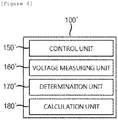
- FIG. 4 is a block diagram illustrating a configuration of an apparatus 100' for measuring insulation resistance according to an embodiment of the present invention.
- the insulation resistance measuring apparatus 100' may include a control unit 150', a voltage measuring unit 160', a determination unit 170', and a calculation unit 180'.
- the insulation resistance measuring apparatus 100' does not include only the first resistance unit 110, the second resistance unit 120, the first switch unit 130, and the second switch unit 140 of the insulation resistance measuring system 100, and may include the control unit 150', the voltage measuring unit 160', the determination unit 170', and the calculation unit 180', which play the same roles as the control unit 150, the voltage measuring unit 160, the determination unit 170, and the calculation unit 180.
- control unit 150', the voltage measuring unit 160', the determination unit 170', and the calculation unit 180' of the insulation resistance measuring apparatus 100' are components that play the same roles as the control unit 150, the voltage measuring unit 160, the determination unit 170, and the calculation unit 180 of the insulation resistance measuring system 100, a repeated description will be omitted.
- the insulation resistance measuring apparatus 100' is connected to the battery pack 10, which previously includes the first resistance unit 110, the second resistance unit 120, the first switch unit 130, and the second switch unit 140 of the insulation resistance measuring system 100, thereby measuring the insulation resistance of the battery pack 10.
Landscapes
- Physics & Mathematics (AREA)
- General Physics & Mathematics (AREA)
- Measurement Of Resistance Or Impedance (AREA)
- Testing Of Short-Circuits, Discontinuities, Leakage, Or Incorrect Line Connections (AREA)
Abstract
Description
- This application claims priority to and the benefit of Korean Patent Application No.
10-2015-0160566 - The present invention relates to an insulation resistance measuring system and device, and more particularly, to an insulation resistance measuring system and device which determine whether first voltage of a first measurement resistance connected with a positive electrode insulation resistance in parallel and second voltage of a second measurement resistance connected with a negative electrode insulation resistance in parallel converge, respectively, control connection between the positive electrode insulation resistance and the negative electrode insulation resistance and the first and second measurement resistances according to whether the first voltage and the second voltage converge, respectively, and calculate resistance values of the positive electrode insulation resistance and the negative electrode insulation resistance by using convergence values of the first voltage and the second voltage, in order to measure the positive electrode insulation resistance and the negative electrode insulation resistance connected to both terminals of a battery pack with a capacitor, respectively.
- An energy storage system (ESS), an electric vehicle (EV), and the like, which use a high-voltage battery pack, are equipped with a system that automatically interrupts power when an emergency situation occurs. The "emergency situation" refers to an excessive short circuit, insulation breakdown, etc., which are caused by aging of an associated component, and an excessive short circuit, insulation breakage, etc., which are caused by a short circuit caused by component breakage due to an external impact.
- When an emergency situation occurs, a command for interrupting main power is transmitted from a higher-order component for controlling high-voltage components such as a battery management system (BMS) or a hybrid control unit (HCU), thereby controlling the power. The high-voltage associated component monitors voltage and current of a line connecting the power through a series of programs or sensors, and interrupts the main power through CAN communication or signal transmission when voltage and current, which are out of a normal range, are detected or there occurs leakage current, which is equal to or higher than an allowable value, and when there occurs insulation resistance breakage, which is equal or higher than the allowable value.
- As described above, it is very important to measure insulation resistance in the ESS, the EV, and the like using the high-voltage battery pack. Examples of a method for measuring the leakage current of the battery pack include a method of forcing direct current (DC) to flow by breaking insulation, and such a method has a disadvantage in that the insulation is broken while the insulation resistance is measured.
- There is a method of measuring an insulation resistance component by connecting a capacitor to a battery pack and applying an AC signal to the capacitor in order to solve the disadvantage. However, the method also has a disadvantage in that since current charging the capacitor and discharged current need to pass through the same circuit, there are a lot of limits in designing the circuit.
- Further, when a voltage measurement time for measuring the insulation resistance is delayed due to a delay of voltage falling and rising by a capacitor component, such that the insulation breakage occurs, there is a problem in that the insulation breakage cannot be rapidly detected.
- Therefore, in order to solve the aforementioned problem, the present inventors have invented an insulation resistance measuring system and device, which determine whether first voltage of a first measurement resistance connected with a positive electrode insulation resistance in parallel and second voltages of second measurement resistances connected with a negative electrode insulation resistance in parallel converge, respectively, control connection of the positive electrode insulation resistance and the negative electrode insulation resistance and the first and second measurement resistances according to whether the first and second voltages converge, respectively, and calculate resistance values of the positive electrode insulation resistance and the negative electrode insulation resistance by using convergence values of the first and second voltages.
- Korean Patent Unexamined Publication No.
10-2012-0136211 - The present invention is contrived to solve the problem and an object of the present invention is to provide an insulation resistance measuring system and device, which can rapidly detect insulation breakage by determining whether voltage of measurement voltage connected to the insulation resistance in parallel converges when insulation breakage occurs due to a delay of voltage falling and rising by a capacitor provided in a battery packet.
- A system for measuring insulation resistance according to an exemplary embodiment of the present invention includes: a first resistance unit which is connected with a positive electrode insulation resistance in parallel; a first switch unit which applies current to the positive electrode insulation resistance and the first resistance unit or interrupts the positive electrode insulation resistance and the first resistance unit; a second resistance unit which is connected with the negative electrode insulation resistance in parallel; a second switch unit which applies the current to the negative electrode insulation resistance and the second resistance unit or interrupts the negative electrode insulation resistance and the second resistance unit; a determination unit which determines whether first voltage and second voltage converge, respectively, based on change values of the first voltage and the second voltage applied to the first resistance unit and the second resistance unit, respectively; a control unit which controls the first and second switch units in response to whether the first voltage and the second voltage converge, respectively; and a calculation unit which calculates a resistance value of each of the positive electrode insulation resistance and the negative electrode insulation resistance by using convergence values of the first voltage and the second voltage.
- The first resistance unit may include: a first measurement resistance; and a first scale resistance which is connected with the first measurement resistance in series and has a resistance value of a predetermined resistance ratio to the resistance value of the first measurement resistance.
- The second resistance unit may include: a second measurement resistance; and a second scale resistance which is connected with the second measurement resistance in series and has a resistance value of a predetermined resistance ratio to the resistance value of the second measurement resistance.
- The insulation resistance apparatus may further include a voltage measuring unit which measures voltage applied between the first measurement resistance and a ground to output the measured voltage as the first voltage and measures voltage applied between the second measurement resistance and the ground to output the measured voltage as the second voltage.
- The determination unit may determine that the first voltage converges when the change value of the first voltage is equal to or less than a predetermined change value.
- The control unit may turn off the first switch unit and turn on the second switch unit when it is determined that the first voltage converges according to the determination result of the determination unit.
- The determination unit may determine that the second voltage converges when the change value of the second voltage is equal to or less than the predetermined change value.
- The control unit may turn off the second switch unit and turn on the first switch unit when it is determined that the second voltage converges according to the determination result of the determination unit.
- An apparatus for measuring insulation resistance according to an exemplary embodiment of the present invention includes: a determination unit which determines whether first voltage and second voltage converge, respectively, based on change values of the first voltage and the second voltage applied to a first resistance unit connected with the positive electrode insulation resistance in parallel and a second resistance unit connected with the negative electrode insulation resistance in parallel, respectively; a control unit which controls a first switch applying current to the positive electrode insulation resistance or interrupting the positive electrode insulation resistance and the first resistance unit and a second switch unit applying the current to the negative electrode insulation resistance and the second resistance unit or interrupting the negative electrode insulation resistance and the second resistance unit, in response to whether the first voltage and the second voltage converge, respectively; and a calculation unit which calculates a resistance value of each of the positive electrode insulation resistance and the negative electrode insulation resistance by using convergence values of the first voltage and the second voltage.
- The apparatus for measuring insulation resistance may further include a voltage measuring unit which measures voltage applied between a first measurement resistance included in the first resistance unit and a ground to output the measured voltage as the first voltage and measures voltage applied between a second measurement resistance included in the second resistance unit and the ground to output the measured voltage as the second voltage.
- The determination unit may determine that the first voltage converges when the change value of the first voltage is equal to or less than a predetermined change value.
- The control unit may turn off the first switch unit and turn on the second switch unit when it is determined that the first voltage converges according to the determination result of the determination unit.
- The determination unit may determine that the second voltage converges when the change value of the second voltage is equal to or less than the predetermined change value.
- The control unit may turn off the second switch unit and turn on the first switch unit when it is determined that the second voltage converges according to the determination result of the determination unit.
- An insulation resistance measuring system and device according to the embodiments of the present invention has an effect in that an insulation resistance value is calculated by detecting that voltage of measurement resistance connected with the insulation resistance in parallel more rapidly converges than a normal state as insulation breakage occurs, thereby rapidly determining the insulation breakage.
- Further, the present invention has an effect in which a measurement period of the insulation resistance can be shortened by not controlling electrical connection of the measurement resistance connected with the insulation resistance in parallel every predetermined period but controlling the electrical connection according to whether the voltage of the measurement resistance converges.
-
-
FIG. 1 is a block diagram illustrating a configuration of a system for measuring insulation resistance according to an embodiment of the present invention. -
FIG. 2 is a circuit diagram illustrating electrical connection of the system for measuring insulation resistance according to an embodiment of the present invention. -
FIG. 3 is a graph illustrating first voltage and second voltage measured by a voltage measuring unit according to the time. -
FIG. 4 is a block diagram illustrating a configuration of an apparatus for measuring insulation resistance according to an embodiment of the present invention. - The present invention will be described below in detail with reference to the accompanying drawings. Herein, the repeated description and the detailed description of publicly-known function and configuration that may make the gist of the present invention unnecessarily ambiguous will be omitted. Embodiments of the present invention are provided for more completely describing the present invention to those skilled in the art. Accordingly, shapes, sizes, and the like of elements in the drawings may be exaggerated for clearer explanation.
- Throughout the specification, unless explicitly described to the contrary, a case where any part "includes" any component will be understood to imply the inclusion of stated components but not the exclusion of any other component.
- In addition, the term "unit" disclosed in the specification means a unit that processes at least one function or operation, and the unit may be implemented by hardware or software or a combination of hardware and software.
-
FIG. 1 is a block diagram illustrating a configuration of asystem 100 for measuring insulation resistance according to an embodiment of the present invention, andFIG. 2 is a circuit diagram illustrating electrical connection of an apparatus for measuring insulation resistance according to the embodiment of the present invention. - Referring to
FIGS. 1 and2 , the insulationresistance measuring system 100 may include afirst resistance unit 110, asecond resistance unit 120, afirst switch unit 130, asecond switch unit 140, acontrol unit 150, avoltage measuring unit 160, adetermination unit 170, and acalculation unit 180. The insulationresistance measuring system 100 illustrated inFIGS. 1 and2 is just an embodiment, and the constituent elements thereof are not limited to the embodiment illustrated inFIGS. 1 and2 , and as necessary, the constituent elements may be added, modified, or deleted. - The insulation
resistance measuring system 100 according to the exemplary embodiment of the present invention may measure a positiveelectrode insulation resistance 11 and a negativeelectrode insulation resistance 12 connected to a positive electrode (+) and a negative electrode (-) of a battery pack, respectively. In this case, apositive electrode capacitor 13 and anegative electrode capacitor 14 may be connected to the positiveelectrode insulation resistance 11 and the negativeelectrode insulation resistance 12, respectively, in parallel. As a result, a delay of voltage falling and rising may occur in the positiveelectrode insulation resistance 11 and the negativeelectrode insulation resistance 12 due to thepositive electrode capacitor 13 and thenegative electrode capacitor 14. - The delay of the voltage falling and rising may be changed according to conditions such as whether voltage, current, and the insulation resistance of the battery pack are normal.
- Therefore, the insulation
resistance measuring system 100 according to the present invention may change measurement times of the positiveelectrode insulation resistance 11 and the negativeelectrode insulation resistance 12 in response to the delay of the voltage falling and rising. - To this end, the
first resistance unit 110 may be connected with the positiveelectrode insulation resistance 11 in parallel, and thesecond resistance unit 120 may be connected with the negativeelectrode insulation resistance 12 in parallel. - In more detail, the
first resistance unit 110 may include afirst measurement resistance 111 and may further include afirst scale resistance 112 connected with thefirst measurement resistance 111 in series. - In this case, a ratio of a resistance value of the
first measurement resistance 111 and a resistance value of thefirst scale resistance 112 may be a predetermined resistance ratio. - Herein, the predetermined resistance ratio may be the ratio of the resistance value of the
first measurement resistance 111 and the resistance value of thefirst scale resistance 112 set to lower and measure the voltage of abattery pack 10, which is applied to thefirst measurement resistance 111. - The
second resistance unit 120 may include asecond measurement resistance 121 and may further include asecond scale resistance 122 connected with thesecond measurement resistance 121 in series. - In this case, a ratio of a resistance value of the
second measurement resistance 121 and a resistance value of thesecond scale resistance 122 may be a predetermined resistance ratio. - Herein, the predetermined resistance ratio may be the ratio of the resistance value of the
second measurement resistance 121 and the resistance value of thesecond scale resistance 122, which are set to lower and measure the voltage of thebattery pack 10, which is applied to thesecond measurement resistance 121. - Meanwhile, the
second resistance unit 120 may further include avoltage source 123 connected with thesecond measurement resistance 121 in series. - The
voltage source 123 is connected between thesecond measurement resistance 121 and a ground to serve to apply the voltage so that the voltage applied between thesecond measurement resistance 121 and the ground has a positive value. - The
first switch unit 130 may serve to apply current to the positiveelectrode insulation resistance 11 and thefirst resistance unit 110 or interrupts the positiveelectrode insulation resistance 11 and thefirst resistance unit 110, and thesecond switch unit 140 may serve to apply the current to the positiveelectrode insulation resistance 12 and thesecond resistance unit 120 or interrupts the positiveelectrode insulation resistance 12 and thesecond resistance unit 120. - In this case, the
control unit 150 may control operation states of thefirst switch unit 130 and thesecond switch unit 140 to an on or off state. - The
control unit 150 may control thefirst switch unit 130 to the on state and thesecond switch unit 140 to the off state at the time of an initial insulation resistance measurement. - Thereafter, the
control unit 150 may serve to control the operation states of thefirst switch unit 130 and thesecond switch unit 140 in response to a determination result of thedetermination unit 170 to be described below. The control of the operation states of the first andsecond switch units control unit 150 according to the determination result of thedetermination unit 170 will be described below. - The
voltage measuring unit 160 may serve to measure the voltage applied between thefirst measurement resistance 111 and the ground and output the measured voltage as the first voltage. - Further, the
voltage measuring unit 160 may serve to measure the voltage applied between thesecond measurement resistance 121 and the ground and output the measured voltage as the second voltage. - To this end, the
voltage measuring unit 160 may further include an AD converter that converts an analog voltage signal into a digital voltage signal. Herein, the digital voltage signal may be a digital signal acquired by outputting the voltage value according to the time by a graph. -
FIG. 3 is a graph illustrating first voltage Vp and second voltage Vn measured by thevoltage measuring unit 160 according to the time. - Referring to
FIG. 3 , during intervals of t1, t3, t5, and t7, when thefirst switch unit 130 is controlled to the on state and thesecond switch unit 140 is controlled to on the off state, the voltage measured by thevoltage measuring unit 160 may be the first voltage Vp and the second voltage Vn. - In more detail, when the
first switch unit 130 is controlled to the on state and thesecond switch unit 140 is controlled to the off state, thefirst measurement resistance 111 is connected with thebattery pack 10, the first voltage rises, and then the first voltage may converge to predetermined voltage due to thepositive electrode capacitor 13. - On the contrary, during intervals of t2, t4, t6, and t8, when the
second switch unit 140 is controlled to the on state and thefirst switch unit 130 is controlled to the off state, the voltage measured by thevoltage measuring unit 160 may be the first voltage and the second voltage. - When the
second switch unit 140 is controlled to the on state and thefirst switch unit 130 is controlled to the off state, thesecond measurement resistance 121 is connected with thebattery pack 10, the second voltage falls from the voltage boosted from thevoltage source 123, and then the second voltage may converge to predetermined voltage due to thenegative electrode capacitor 14. - The intervals of t5 to t8 may be the first voltage and the second voltage measured from the
voltage measuring unit 160 at the time when the insulation resistance is broken. - When the insulation resistance is broken, magnitudes of the voltages, which are applied to the
first measurement resistance 111 and thesecond measurement resistance 121 connected with the positiveelectrode insulation resistance 13 and the negativeelectrode insulation resistance 14, respectively, in parallel, may increase. - As a result, after the
first switch unit 130 and thesecond switch unit 140 are changed to the on or off state, the first voltage and the second voltage may converge to predetermined voltage earlier than the case where the insulation resistance is in the normal state. - The
determination unit 170 may serve to determine whether the first voltage and the second voltage measured by thevoltage measuring unit 160 converges, respectively. - In more detail, the
determination unit 170 may determine whether the first voltage and the second voltage converge, respectively, based on change values of the first voltage and the second voltage and transmit a determination result to thecontrol unit 150 and thecalculation unit 180 to be described below. - In order to determine whether the first voltage converges, the
determination unit 170 compares the change value of the first voltage with a predetermined change value, and when the change value of the first voltage is equal to or less than the predetermined change value, thedetermination unit 170 may determine that the first voltage converges. - Similarly thereto, in order to determine whether the second voltage converges, the
determination unit 170 compares the change value of the second voltage with a predetermined change value, and when the change value of the second voltage is equal to or less than the predetermined change value, thedetermination unit 170 may determine that the second voltage converges. Herein, the change values of the first voltage and the second voltage may be voltage values in which the first voltage and the second voltage are changed per unit time, and the predetermined change value may be a criterion value for determining that the voltage change ends as the delay of the voltage falling and rising ends due to thecapacitor 13 in the case of the first voltage and the second voltage. - When it is determined that the first voltage converges according to the determination result of the
determination unit 170, thecontrol unit 150 may turn off thefirst switch unit 130 and turn on thesecond switch unit 140. - On the contrary, when it is determined that the second voltage converges according to the determination result of the
determination unit 170, thecontrol unit 150 may turn off thesecond switch unit 140 and turn on thefirst switch unit 130. - Therefore, the
control unit 150 does not previously set a period of changing the on or off states of the first switch unit and the second switch unit but flexibly changes the period according to whether the first voltage and the second voltage converge, respectively, in order to measure the insulation resistance, thereby shortening a time required for measuring the insulation resistance. - The
calculation unit 180 may calculate the resistance values of the positiveelectrode insulation resistance 11 and the negativeelectrode insulation resistance 12 by using the first voltage at the time when it is determined by thedetermination unit 170 that the first voltage converges, that is, the convergence value of the first voltage, the second voltage at the time when it is determined by thedetermination unit 170 hat the second voltage converges, that is, the convergence value of the second voltage, and the voltage of thebattery pack 10 at the calculation time. - In this case, the voltage of the
battery pack 10 may be received from a battery management system (BMS) managing the battery pack. -
FIG. 4 is a block diagram illustrating a configuration of an apparatus 100' for measuring insulation resistance according to an embodiment of the present invention. - Referring to
FIG. 4 , the insulation resistance measuring apparatus 100' may include a control unit 150', a voltage measuring unit 160', a determination unit 170', and a calculation unit 180'. When the insulationresistance measuring system 100 illustrated inFIGS. 1 and2 and the insulation resistance measuring apparatus 100' illustrated inFIG. 4 are compared with each other, the insulation resistance measuring apparatus 100' does not include only thefirst resistance unit 110, thesecond resistance unit 120, thefirst switch unit 130, and thesecond switch unit 140 of the insulationresistance measuring system 100, and may include the control unit 150', the voltage measuring unit 160', the determination unit 170', and the calculation unit 180', which play the same roles as thecontrol unit 150, thevoltage measuring unit 160, thedetermination unit 170, and thecalculation unit 180. - Therefore, as described above, since the control unit 150', the voltage measuring unit 160', the determination unit 170', and the calculation unit 180' of the insulation resistance measuring apparatus 100' are components that play the same roles as the
control unit 150, thevoltage measuring unit 160, thedetermination unit 170, and thecalculation unit 180 of the insulationresistance measuring system 100, a repeated description will be omitted. - Meanwhile, the insulation resistance measuring apparatus 100' is connected to the
battery pack 10, which previously includes thefirst resistance unit 110, thesecond resistance unit 120, thefirst switch unit 130, and thesecond switch unit 140 of the insulationresistance measuring system 100, thereby measuring the insulation resistance of thebattery pack 10. - The present invention has been described with reference to the preferred embodiments, but those skilled in the art will understand that the present invention can be variously modified and changed without departing from the spirit and the scope of the present invention which are defined in the appended claims.
-
- 100:
- Insulation resistance measuring system
- 100':
- Insulation resistance measuring apparatus
- 110:
- First resistance unit
- 111:
- First measurement resistance
- 112:
- First scale resistance
- 120:
- First resistance unit
- 121:
- Second measurement resistance
- 122:
- Second scale resistance
- 123:
- Voltage source
- 130:
- First switch unit
- 140:
- Second switch unit
- 150:
- Control unit
- 160:
- Voltage measuring unit
- 170:
- Determination unit
- 180:
- Calculation unit
Claims (14)
- A system for measuring insulation resistance, which measures a positive electrode insulation resistance and a negative electrode insulation resistance connected to both terminals of a battery pack with a capacitor, respectively, the system comprising:a first resistance unit which is connected with the positive electrode insulation resistance in parallel;a first switch unit which applies current to the positive electrode insulation resistance and the first resistance unit or interrupts the positive electrode insulation resistance and the first resistance unit;a second resistance unit which is connected with the negative electrode insulation resistance in parallel;a second switch unit which applies the current to the negative electrode insulation resistance and the second resistance unit or interrupts the negative electrode insulation resistance and the second resistance unit;a determination unit which determines whether first voltage and second voltage converge, respectively, based on change values of the first voltage and the second voltage applied to the first resistance unit and the second resistance unit, respectively;a control unit which controls the first and second switch units in response to whether the first voltage and the second voltage converge, respectively; anda calculation unit which calculates a resistance value of each of the positive electrode insulation resistance and the negative electrode insulation resistance by using convergence values of the first voltage and the second voltage.
- The system of claim 1, wherein the first resistance unit includes
a first measurement resistance, and
a first scale resistance which is connected with the first measurement resistance in series and has a resistance value of a predetermined resistance ratio to the resistance value of the first measurement resistance. - The system of claim 2, wherein the second resistance unit includes
a second measurement resistance, and
a second scale resistance which is connected with the second measurement resistance in series and has a resistance value of a predetermined resistance ratio to the resistance value of the second measurement resistance. - The system of claim 3, further comprising:a voltage measuring unit which measures voltage applied between the first measurement resistance and a ground to output the measured voltage as the first voltage and measures voltage applied between the second measurement resistance and the ground to output the measured voltage as the second voltage.
- The system of claim 1, wherein the determination unit determines that the first voltage converges when the change value of the first voltage is equal to or less than the predetermined change value.
- The system of claim 5, wherein the control unit turns off the first switch unit and turns on the second switch unit when it is determined that the first voltage converges according to the determination result of the determination unit.
- The system of claim 1, wherein the determination unit determines that the second voltage converges when the change value of the second voltage is equal to or less than the predetermined change value.
- The system of claim 7, wherein the control unit turns off the second switch unit and turns on the first switch unit when it is determined that the second voltage converges according to the determination result of the determination unit.
- An apparatus for measuring insulation resistance, which measures a positive electrode insulation resistance and a negative electrode insulation resistance connected to both terminals of a battery pack with a capacitor, respectively, the apparatus comprising:a determination unit which determines whether first voltage and second voltage converge, respectively, based on change values of the first voltage and the second voltage applied to a first resistance unit connected with the positive electrode insulation resistance in parallel and a second resistance unit connected with the negative electrode insulation resistance in parallel, respectively;a control unit which controls a first switch applying current to the positive electrode insulation resistance and the first resistance unit or interrupting the positive electrode insulation resistance and the first resistance unit and a second switch unit applying the current to the negative electrode insulation resistance and the second resistance unit or interrupting the negative electrode insulation resistance and the second resistance unit, in response to whether the first voltage and the second voltage converge, respectively; anda calculation unit which calculates a resistance value of each of the positive electrode insulation resistance and the negative electrode insulation resistance by using convergence values of the first voltage and the second voltage.
- The apparatus of claim 9, further comprising:a voltage measuring unit which measures voltage applied between a first measurement resistance included in the first resistance unit and a ground to output the measured voltage as the first voltage and measures voltage applied between a second measurement resistance included in the second resistance unit and the ground to output the measured voltage as the second voltage.
- The apparatus of claim 10, wherein the determination unit determines that the first voltage converges when the change value of the first voltage is equal to or less than a predetermined change value.
- The apparatus of claim 11, wherein the control unit turns off the first switch unit and turns on the second switch unit when it is determined that the first voltage converges according to the determination result of the determination unit.
- The apparatus of claim 10, wherein the determination unit determines that the second voltage converges when a change value of the second voltage is equal to or less than a predetermined change value.
- The apparatus of claim 13, wherein the control unit turns off the second switch unit and turns on the first switch unit when it is determined that the second voltage converges according to the determination result of the determination unit.
Applications Claiming Priority (2)
| Application Number | Priority Date | Filing Date | Title |
|---|---|---|---|
| KR1020150160566A KR101936220B1 (en) | 2015-11-16 | 2015-11-16 | System and apparatus for measuring of insulation resistance |
| PCT/KR2016/013185 WO2017086687A1 (en) | 2015-11-16 | 2016-11-16 | Insulation resistance measuring system and device |
Publications (3)
| Publication Number | Publication Date |
|---|---|
| EP3258280A1 true EP3258280A1 (en) | 2017-12-20 |
| EP3258280A4 EP3258280A4 (en) | 2018-07-11 |
| EP3258280B1 EP3258280B1 (en) | 2022-07-27 |
Family
ID=58719044
Family Applications (1)
| Application Number | Title | Priority Date | Filing Date |
|---|---|---|---|
| EP16866639.4A Active EP3258280B1 (en) | 2015-11-16 | 2016-11-16 | Insulation resistance measuring system and device |
Country Status (7)
| Country | Link |
|---|---|
| US (1) | US10534032B2 (en) |
| EP (1) | EP3258280B1 (en) |
| JP (1) | JP2018508785A (en) |
| KR (1) | KR101936220B1 (en) |
| CN (1) | CN107407713B (en) |
| PL (1) | PL3258280T3 (en) |
| WO (1) | WO2017086687A1 (en) |
Cited By (4)
| Publication number | Priority date | Publication date | Assignee | Title |
|---|---|---|---|---|
| CN109917240A (en) * | 2019-03-07 | 2019-06-21 | 深圳市盛弘电气股份有限公司 | A kind of bilateral D.C. isolation detection method and system |
| CN111751744A (en) * | 2020-06-30 | 2020-10-09 | 上海瓶安新能源科技有限公司 | Insulation monitoring circuit and monitoring method for lithium battery pack |
| EP4145161A1 (en) * | 2021-09-06 | 2023-03-08 | Volvo Truck Corporation | An electric insulation monitoring arrangement |
| CN117413187A (en) * | 2021-11-22 | 2024-01-16 | 株式会社Lg新能源 | Insulation resistance measuring device and battery system including the insulation resistance measuring device |
Families Citing this family (21)
| Publication number | Priority date | Publication date | Assignee | Title |
|---|---|---|---|---|
| KR102065822B1 (en) | 2017-06-27 | 2020-02-11 | 주식회사 엘지화학 | System and method for calculating insulation resistance |
| DE102017119992A1 (en) * | 2017-08-31 | 2019-02-28 | Lisa Dräxlmaier GmbH | A monitoring device for monitoring an electrical energy source in terms of its source voltage and its insulation resistances and high-voltage system and method for operating the monitoring device |
| CN108333428B (en) * | 2017-12-30 | 2020-09-18 | 宁德时代新能源科技股份有限公司 | Insulation resistance measuring equipment and method |
| TWI661204B (en) * | 2018-07-16 | 2019-06-01 | 昆山富士錦電子有限公司 | Insulation resistance measuring device |
| CN109061309B (en) * | 2018-10-11 | 2021-03-26 | 沃尔特电子(苏州)有限公司 | Vehicle body insulation measuring circuit and measuring method |
| CN109444549B (en) * | 2018-10-24 | 2021-04-06 | 宁波普瑞均胜汽车电子有限公司 | Rapid detection method for vehicle body insulation |
| KR102742037B1 (en) | 2019-01-03 | 2024-12-13 | 주식회사 엘지에너지솔루션 | Insulation resistance measurement apparatus and method thereof |
| KR102672495B1 (en) * | 2019-03-15 | 2024-06-07 | 에스케이온 주식회사 | Apparatus for measuring insulation resistance |
| KR102145926B1 (en) * | 2019-04-02 | 2020-08-20 | 가보 주식회사 | Voltage-type ground detection apparatus and method using multiple DC power supply voltages mixed together |
| KR102181229B1 (en) * | 2019-06-28 | 2020-11-24 | (주)에이치엠지 | Apparatus and method for measuring resistance measurement |
| JP2021050963A (en) * | 2019-09-24 | 2021-04-01 | 矢崎総業株式会社 | Insulation resistance detection circuit |
| JP7365225B2 (en) * | 2019-12-20 | 2023-10-19 | 新電元工業株式会社 | Insulation monitoring device and power supply device equipped with the same |
| KR102804359B1 (en) | 2020-04-13 | 2025-05-09 | 에스케이온 주식회사 | Apparatus for measuring insulation resistance |
| WO2022000206A1 (en) * | 2020-06-29 | 2022-01-06 | 华为数字能源技术有限公司 | Insulation resistance detection circuit, method and device and storage medium thereof |
| CN111965428B (en) * | 2020-08-05 | 2023-03-24 | 东软睿驰汽车技术(沈阳)有限公司 | Insulation resistance detection method, device, equipment and storage medium |
| KR102861599B1 (en) * | 2020-09-29 | 2025-09-17 | 주식회사 엘지에너지솔루션 | ISOLATION STATE diagnosis METHOD AND BATTERY SYSTEM USING THE SAME |
| KR102920220B1 (en) | 2021-11-12 | 2026-01-30 | 주식회사 엘지에너지솔루션 | Apparatus for measuring insulation resistance |
| KR102818543B1 (en) * | 2022-01-17 | 2025-06-11 | 두원중공업(주) | Apparatus for Motor Isolation Failure Detection in Electric Compressor |
| JP2023107032A (en) * | 2022-01-21 | 2023-08-02 | 株式会社デンソーテン | INSULATION RESISTANCE DETECTION DEVICE AND FAILURE DETECTION METHOD |
| KR102750696B1 (en) * | 2022-04-25 | 2025-01-09 | 충북대학교 산학협력단 | Insulation monitoring device having a system connection check function with power line and operating method thereof |
| KR102909907B1 (en) * | 2025-03-05 | 2026-01-08 | 주식회사 아이엑스 | Electric Vehicle Charging Port Insulation Resistance Measuring Device |
Family Cites Families (17)
| Publication number | Priority date | Publication date | Assignee | Title |
|---|---|---|---|---|
| DE10300539B4 (en) * | 2003-01-09 | 2007-05-24 | Daimlerchrysler Ag | Circuit and method for detecting insulation faults |
| JP4064292B2 (en) * | 2003-04-28 | 2008-03-19 | 本田技研工業株式会社 | Ground fault detector |
| JP2006343267A (en) * | 2005-06-10 | 2006-12-21 | Chugoku Electric Power Co Inc:The | Insulation resistance measuring instrument of dc circuit, electrostatic capacitance measuring instrument, insulation resistance measuring method and electrostatic capacitance measuring method |
| KR101114317B1 (en) | 2009-03-23 | 2012-02-14 | 에스케이이노베이션 주식회사 | Insulation resistance measuring circuit not affected by battery voltage |
| EP2333568A1 (en) * | 2009-12-10 | 2011-06-15 | Johnson Controls Saft Advanced Power Solutions LLC | Determination of insulation resistance of an electric DC circuit |
| KR101354583B1 (en) | 2010-09-17 | 2014-01-22 | 에스케이이노베이션 주식회사 | Insulation resistance measurement circuit |
| KR20120136211A (en) | 2011-06-08 | 2012-12-18 | 이영희 | Self-tapping screw hvaing curved area in rear flank |
| EP2570289B1 (en) * | 2011-09-16 | 2018-08-15 | Samsung SDI Co., Ltd. | Device for determining the insulation resistance of a high-voltage battery system |
| WO2013147494A1 (en) * | 2012-03-26 | 2013-10-03 | 주식회사 엘지화학 | Device and method for measuring insulation resistance of battery |
| JP5947584B2 (en) * | 2012-03-27 | 2016-07-06 | 矢崎総業株式会社 | Insulation state detector |
| PL2796887T3 (en) * | 2012-03-27 | 2020-05-18 | Lg Chem, Ltd. | Isolation resistance measurement apparatus having fault self-diagnosis function and fault self-diagnosing method using the same |
| PL2720056T3 (en) | 2012-04-04 | 2021-07-12 | Lg Chem, Ltd. | Isolation resistance measuring apparatus having fault self-diagnosing function and self-diagnosing method using the same |
| KR101473396B1 (en) * | 2012-05-15 | 2014-12-16 | 주식회사 엘지화학 | Apparatus and method for measuring isolation resistance of battery using extended kalman filter |
| KR20130128597A (en) | 2012-05-17 | 2013-11-27 | 현대모비스 주식회사 | Insulation resistance sensing circuit and battery management system including the same |
| KR101361285B1 (en) * | 2012-09-12 | 2014-02-11 | 기아자동차주식회사 | Fault detecting method of vehicle |
| KR101771226B1 (en) * | 2014-10-02 | 2017-09-05 | 주식회사 엘지화학 | Isolation resistance measurement apparatus that can rapidly measure isolation resistance |
| JP6633585B2 (en) * | 2017-10-04 | 2020-01-22 | 矢崎総業株式会社 | Ground fault detector |
-
2015
- 2015-11-16 KR KR1020150160566A patent/KR101936220B1/en active Active
-
2016
- 2016-11-16 EP EP16866639.4A patent/EP3258280B1/en active Active
- 2016-11-16 PL PL16866639.4T patent/PL3258280T3/en unknown
- 2016-11-16 CN CN201680017975.2A patent/CN107407713B/en active Active
- 2016-11-16 JP JP2017548920A patent/JP2018508785A/en active Pending
- 2016-11-16 WO PCT/KR2016/013185 patent/WO2017086687A1/en not_active Ceased
- 2016-11-16 US US15/559,937 patent/US10534032B2/en active Active
Cited By (8)
| Publication number | Priority date | Publication date | Assignee | Title |
|---|---|---|---|---|
| CN109917240A (en) * | 2019-03-07 | 2019-06-21 | 深圳市盛弘电气股份有限公司 | A kind of bilateral D.C. isolation detection method and system |
| CN109917240B (en) * | 2019-03-07 | 2021-04-06 | 深圳市盛弘电气股份有限公司 | Bilateral direct-current insulation detection method and system |
| CN111751744A (en) * | 2020-06-30 | 2020-10-09 | 上海瓶安新能源科技有限公司 | Insulation monitoring circuit and monitoring method for lithium battery pack |
| EP4145161A1 (en) * | 2021-09-06 | 2023-03-08 | Volvo Truck Corporation | An electric insulation monitoring arrangement |
| US12044749B2 (en) | 2021-09-06 | 2024-07-23 | Volvo Truck Corporation | Electric insulation monitoring arrangement |
| CN117413187A (en) * | 2021-11-22 | 2024-01-16 | 株式会社Lg新能源 | Insulation resistance measuring device and battery system including the insulation resistance measuring device |
| EP4332586A4 (en) * | 2021-11-22 | 2024-10-02 | LG Energy Solution, Ltd. | DEVICE FOR MEASURING INSULATION RESISTANCE AND BATTERY SYSTEM THEREOF |
| US12535517B2 (en) | 2021-11-22 | 2026-01-27 | Lg Energy Solution, Ltd. | Insulation resistance measuring device and battery system including the same |
Also Published As
| Publication number | Publication date |
|---|---|
| US20180074113A1 (en) | 2018-03-15 |
| EP3258280A4 (en) | 2018-07-11 |
| WO2017086687A1 (en) | 2017-05-26 |
| EP3258280B1 (en) | 2022-07-27 |
| KR101936220B1 (en) | 2019-01-08 |
| PL3258280T3 (en) | 2022-11-21 |
| US10534032B2 (en) | 2020-01-14 |
| KR20170057004A (en) | 2017-05-24 |
| CN107407713A (en) | 2017-11-28 |
| JP2018508785A (en) | 2018-03-29 |
| CN107407713B (en) | 2020-09-08 |
Similar Documents
| Publication | Publication Date | Title |
|---|---|---|
| EP3258280B1 (en) | Insulation resistance measuring system and device | |
| US10749148B2 (en) | Scalable modular design of a 48-volt li-ion battery management system | |
| EP2866038B1 (en) | Leak detection device | |
| US10495692B2 (en) | Battery monitor | |
| US9880224B2 (en) | Battery system monitoring device | |
| US9130381B2 (en) | Systems and methods for identifying and monitoring a battery charger | |
| US20160372940A1 (en) | Battery Management System for Controlling an Energy Storage Assembly and Method for Charging and Discharging an Energy Storage Assembly | |
| US8963503B2 (en) | Safety discharge apparatus for an electrical storage element | |
| US20180358837A1 (en) | Charging control device | |
| US20120306436A1 (en) | Electric storage device condition determination device, electrically chargeable device, and method of determining electric storage device condition | |
| US9847663B2 (en) | Secondary-battery charging system and method and battery pack | |
| EP3050209B1 (en) | Pre-charging system for a capacitor in a voltage inverter for an electric motor | |
| KR102082380B1 (en) | Method and system for controling driving current of load | |
| WO2016132514A1 (en) | Electricity storage system, electricity storage control method, and electricity storage control program | |
| US10177560B2 (en) | Battery monitoring device | |
| US9350168B2 (en) | Voltage equalization apparatus for connecting power storage unit racks and power storage system including the same | |
| CN105322612A (en) | Charge and discharge control circuit and battery device | |
| WO2017131164A1 (en) | Charging circuit | |
| US10972017B2 (en) | Control unit for controlling an inverter, inverter and method for operating an inverter | |
| JP2016082642A (en) | Overcurrent abnormality detection device and overcurrent abnormality detection method | |
| KR20140131174A (en) | Apparatus for battery management having precharge function with pulse width modulation and method thereof | |
| JP2018137058A (en) | Battery device and battery device control method | |
| KR101595935B1 (en) | Apparatus for interrupt battery use by measuring intensity of magnetic field and method thereof | |
| CN112549964B (en) | Contactor sintering state monitoring method, battery manager, vehicle and medium | |
| CN108124465A (en) | Method and system for monitoring and controlling battery load capacity |
Legal Events
| Date | Code | Title | Description |
|---|---|---|---|
| STAA | Information on the status of an ep patent application or granted ep patent |
Free format text: STATUS: THE INTERNATIONAL PUBLICATION HAS BEEN MADE |
|
| PUAI | Public reference made under article 153(3) epc to a published international application that has entered the european phase |
Free format text: ORIGINAL CODE: 0009012 |
|
| STAA | Information on the status of an ep patent application or granted ep patent |
Free format text: STATUS: REQUEST FOR EXAMINATION WAS MADE |
|
| 17P | Request for examination filed |
Effective date: 20170911 |
|
| AK | Designated contracting states |
Kind code of ref document: A1 Designated state(s): AL AT BE BG CH CY CZ DE DK EE ES FI FR GB GR HR HU IE IS IT LI LT LU LV MC MK MT NL NO PL PT RO RS SE SI SK SM TR |
|
| AX | Request for extension of the european patent |
Extension state: BA ME |
|
| RIC1 | Information provided on ipc code assigned before grant |
Ipc: G01R 27/02 20060101ALI20180529BHEP Ipc: G01R 31/36 20060101AFI20180529BHEP Ipc: G01R 27/08 20060101ALI20180529BHEP |
|
| A4 | Supplementary search report drawn up and despatched |
Effective date: 20180607 |
|
| DAV | Request for validation of the european patent (deleted) | ||
| DAX | Request for extension of the european patent (deleted) | ||
| RAP1 | Party data changed (applicant data changed or rights of an application transferred) |
Owner name: LG ENERGY SOLUTION LTD. |
|
| GRAJ | Information related to disapproval of communication of intention to grant by the applicant or resumption of examination proceedings by the epo deleted |
Free format text: ORIGINAL CODE: EPIDOSDIGR1 |
|
| GRAP | Despatch of communication of intention to grant a patent |
Free format text: ORIGINAL CODE: EPIDOSNIGR1 |
|
| GRAP | Despatch of communication of intention to grant a patent |
Free format text: ORIGINAL CODE: EPIDOSNIGR1 |
|
| STAA | Information on the status of an ep patent application or granted ep patent |
Free format text: STATUS: GRANT OF PATENT IS INTENDED |
|
| INTG | Intention to grant announced |
Effective date: 20220216 |
|
| INTC | Intention to grant announced (deleted) | ||
| INTG | Intention to grant announced |
Effective date: 20220302 |
|
| RAP3 | Party data changed (applicant data changed or rights of an application transferred) |
Owner name: LG ENERGY SOLUTION, LTD. |
|
| GRAS | Grant fee paid |
Free format text: ORIGINAL CODE: EPIDOSNIGR3 |
|
| GRAA | (expected) grant |
Free format text: ORIGINAL CODE: 0009210 |
|
| STAA | Information on the status of an ep patent application or granted ep patent |
Free format text: STATUS: THE PATENT HAS BEEN GRANTED |
|
| AK | Designated contracting states |
Kind code of ref document: B1 Designated state(s): AL AT BE BG CH CY CZ DE DK EE ES FI FR GB GR HR HU IE IS IT LI LT LU LV MC MK MT NL NO PL PT RO RS SE SI SK SM TR |
|
| REG | Reference to a national code |
Ref country code: CH Ref legal event code: EP |
|
| REG | Reference to a national code |
Ref country code: AT Ref legal event code: REF Ref document number: 1507415 Country of ref document: AT Kind code of ref document: T Effective date: 20220815 |
|
| REG | Reference to a national code |
Ref country code: DE Ref legal event code: R096 Ref document number: 602016073856 Country of ref document: DE |
|
| REG | Reference to a national code |
Ref country code: IE Ref legal event code: FG4D |
|
| REG | Reference to a national code |
Ref country code: SE Ref legal event code: TRGR |
|
| REG | Reference to a national code |
Ref country code: LT Ref legal event code: MG9D |
|
| REG | Reference to a national code |
Ref country code: NL Ref legal event code: MP Effective date: 20220727 |
|
| PG25 | Lapsed in a contracting state [announced via postgrant information from national office to epo] |
Ref country code: RS Free format text: LAPSE BECAUSE OF FAILURE TO SUBMIT A TRANSLATION OF THE DESCRIPTION OR TO PAY THE FEE WITHIN THE PRESCRIBED TIME-LIMIT Effective date: 20220727 Ref country code: PT Free format text: LAPSE BECAUSE OF FAILURE TO SUBMIT A TRANSLATION OF THE DESCRIPTION OR TO PAY THE FEE WITHIN THE PRESCRIBED TIME-LIMIT Effective date: 20221128 Ref country code: NO Free format text: LAPSE BECAUSE OF FAILURE TO SUBMIT A TRANSLATION OF THE DESCRIPTION OR TO PAY THE FEE WITHIN THE PRESCRIBED TIME-LIMIT Effective date: 20221027 Ref country code: NL Free format text: LAPSE BECAUSE OF FAILURE TO SUBMIT A TRANSLATION OF THE DESCRIPTION OR TO PAY THE FEE WITHIN THE PRESCRIBED TIME-LIMIT Effective date: 20220727 Ref country code: LV Free format text: LAPSE BECAUSE OF FAILURE TO SUBMIT A TRANSLATION OF THE DESCRIPTION OR TO PAY THE FEE WITHIN THE PRESCRIBED TIME-LIMIT Effective date: 20220727 Ref country code: LT Free format text: LAPSE BECAUSE OF FAILURE TO SUBMIT A TRANSLATION OF THE DESCRIPTION OR TO PAY THE FEE WITHIN THE PRESCRIBED TIME-LIMIT Effective date: 20220727 Ref country code: FI Free format text: LAPSE BECAUSE OF FAILURE TO SUBMIT A TRANSLATION OF THE DESCRIPTION OR TO PAY THE FEE WITHIN THE PRESCRIBED TIME-LIMIT Effective date: 20220727 Ref country code: ES Free format text: LAPSE BECAUSE OF FAILURE TO SUBMIT A TRANSLATION OF THE DESCRIPTION OR TO PAY THE FEE WITHIN THE PRESCRIBED TIME-LIMIT Effective date: 20220727 |
|
| REG | Reference to a national code |
Ref country code: AT Ref legal event code: MK05 Ref document number: 1507415 Country of ref document: AT Kind code of ref document: T Effective date: 20220727 |
|
| PG25 | Lapsed in a contracting state [announced via postgrant information from national office to epo] |
Ref country code: IS Free format text: LAPSE BECAUSE OF FAILURE TO SUBMIT A TRANSLATION OF THE DESCRIPTION OR TO PAY THE FEE WITHIN THE PRESCRIBED TIME-LIMIT Effective date: 20221127 Ref country code: HR Free format text: LAPSE BECAUSE OF FAILURE TO SUBMIT A TRANSLATION OF THE DESCRIPTION OR TO PAY THE FEE WITHIN THE PRESCRIBED TIME-LIMIT Effective date: 20220727 Ref country code: GR Free format text: LAPSE BECAUSE OF FAILURE TO SUBMIT A TRANSLATION OF THE DESCRIPTION OR TO PAY THE FEE WITHIN THE PRESCRIBED TIME-LIMIT Effective date: 20221028 |
|
| PG25 | Lapsed in a contracting state [announced via postgrant information from national office to epo] |
Ref country code: SM Free format text: LAPSE BECAUSE OF FAILURE TO SUBMIT A TRANSLATION OF THE DESCRIPTION OR TO PAY THE FEE WITHIN THE PRESCRIBED TIME-LIMIT Effective date: 20220727 Ref country code: RO Free format text: LAPSE BECAUSE OF FAILURE TO SUBMIT A TRANSLATION OF THE DESCRIPTION OR TO PAY THE FEE WITHIN THE PRESCRIBED TIME-LIMIT Effective date: 20220727 Ref country code: DK Free format text: LAPSE BECAUSE OF FAILURE TO SUBMIT A TRANSLATION OF THE DESCRIPTION OR TO PAY THE FEE WITHIN THE PRESCRIBED TIME-LIMIT Effective date: 20220727 Ref country code: CZ Free format text: LAPSE BECAUSE OF FAILURE TO SUBMIT A TRANSLATION OF THE DESCRIPTION OR TO PAY THE FEE WITHIN THE PRESCRIBED TIME-LIMIT Effective date: 20220727 Ref country code: AT Free format text: LAPSE BECAUSE OF FAILURE TO SUBMIT A TRANSLATION OF THE DESCRIPTION OR TO PAY THE FEE WITHIN THE PRESCRIBED TIME-LIMIT Effective date: 20220727 |
|
| REG | Reference to a national code |
Ref country code: DE Ref legal event code: R097 Ref document number: 602016073856 Country of ref document: DE |
|
| PG25 | Lapsed in a contracting state [announced via postgrant information from national office to epo] |
Ref country code: SK Free format text: LAPSE BECAUSE OF FAILURE TO SUBMIT A TRANSLATION OF THE DESCRIPTION OR TO PAY THE FEE WITHIN THE PRESCRIBED TIME-LIMIT Effective date: 20220727 Ref country code: EE Free format text: LAPSE BECAUSE OF FAILURE TO SUBMIT A TRANSLATION OF THE DESCRIPTION OR TO PAY THE FEE WITHIN THE PRESCRIBED TIME-LIMIT Effective date: 20220727 |
|
| PLBE | No opposition filed within time limit |
Free format text: ORIGINAL CODE: 0009261 |
|
| STAA | Information on the status of an ep patent application or granted ep patent |
Free format text: STATUS: NO OPPOSITION FILED WITHIN TIME LIMIT |
|
| P01 | Opt-out of the competence of the unified patent court (upc) registered |
Effective date: 20230512 |
|
| PG25 | Lapsed in a contracting state [announced via postgrant information from national office to epo] |
Ref country code: MC Free format text: LAPSE BECAUSE OF FAILURE TO SUBMIT A TRANSLATION OF THE DESCRIPTION OR TO PAY THE FEE WITHIN THE PRESCRIBED TIME-LIMIT Effective date: 20220727 Ref country code: AL Free format text: LAPSE BECAUSE OF FAILURE TO SUBMIT A TRANSLATION OF THE DESCRIPTION OR TO PAY THE FEE WITHIN THE PRESCRIBED TIME-LIMIT Effective date: 20220727 |
|
| REG | Reference to a national code |
Ref country code: CH Ref legal event code: PL |
|
| 26N | No opposition filed |
Effective date: 20230502 |
|
| REG | Reference to a national code |
Ref country code: BE Ref legal event code: MM Effective date: 20221130 |
|
| PG25 | Lapsed in a contracting state [announced via postgrant information from national office to epo] |
Ref country code: LI Free format text: LAPSE BECAUSE OF NON-PAYMENT OF DUE FEES Effective date: 20221130 Ref country code: CH Free format text: LAPSE BECAUSE OF NON-PAYMENT OF DUE FEES Effective date: 20221130 |
|
| PG25 | Lapsed in a contracting state [announced via postgrant information from national office to epo] |
Ref country code: SI Free format text: LAPSE BECAUSE OF FAILURE TO SUBMIT A TRANSLATION OF THE DESCRIPTION OR TO PAY THE FEE WITHIN THE PRESCRIBED TIME-LIMIT Effective date: 20220727 Ref country code: LU Free format text: LAPSE BECAUSE OF NON-PAYMENT OF DUE FEES Effective date: 20221116 |
|
| PG25 | Lapsed in a contracting state [announced via postgrant information from national office to epo] |
Ref country code: IE Free format text: LAPSE BECAUSE OF NON-PAYMENT OF DUE FEES Effective date: 20221116 |
|
| PG25 | Lapsed in a contracting state [announced via postgrant information from national office to epo] |
Ref country code: BE Free format text: LAPSE BECAUSE OF NON-PAYMENT OF DUE FEES Effective date: 20221130 |
|
| PG25 | Lapsed in a contracting state [announced via postgrant information from national office to epo] |
Ref country code: HU Free format text: LAPSE BECAUSE OF FAILURE TO SUBMIT A TRANSLATION OF THE DESCRIPTION OR TO PAY THE FEE WITHIN THE PRESCRIBED TIME-LIMIT; INVALID AB INITIO Effective date: 20161116 |
|
| PG25 | Lapsed in a contracting state [announced via postgrant information from national office to epo] |
Ref country code: CY Free format text: LAPSE BECAUSE OF FAILURE TO SUBMIT A TRANSLATION OF THE DESCRIPTION OR TO PAY THE FEE WITHIN THE PRESCRIBED TIME-LIMIT Effective date: 20220727 |
|
| PG25 | Lapsed in a contracting state [announced via postgrant information from national office to epo] |
Ref country code: MK Free format text: LAPSE BECAUSE OF FAILURE TO SUBMIT A TRANSLATION OF THE DESCRIPTION OR TO PAY THE FEE WITHIN THE PRESCRIBED TIME-LIMIT Effective date: 20220727 Ref country code: IT Free format text: LAPSE BECAUSE OF FAILURE TO SUBMIT A TRANSLATION OF THE DESCRIPTION OR TO PAY THE FEE WITHIN THE PRESCRIBED TIME-LIMIT Effective date: 20220727 |
|
| PG25 | Lapsed in a contracting state [announced via postgrant information from national office to epo] |
Ref country code: TR Free format text: LAPSE BECAUSE OF FAILURE TO SUBMIT A TRANSLATION OF THE DESCRIPTION OR TO PAY THE FEE WITHIN THE PRESCRIBED TIME-LIMIT Effective date: 20220727 |
|
| PG25 | Lapsed in a contracting state [announced via postgrant information from national office to epo] |
Ref country code: BG Free format text: LAPSE BECAUSE OF FAILURE TO SUBMIT A TRANSLATION OF THE DESCRIPTION OR TO PAY THE FEE WITHIN THE PRESCRIBED TIME-LIMIT Effective date: 20220727 |
|
| PG25 | Lapsed in a contracting state [announced via postgrant information from national office to epo] |
Ref country code: MT Free format text: LAPSE BECAUSE OF FAILURE TO SUBMIT A TRANSLATION OF THE DESCRIPTION OR TO PAY THE FEE WITHIN THE PRESCRIBED TIME-LIMIT Effective date: 20220727 |
|
| PGFP | Annual fee paid to national office [announced via postgrant information from national office to epo] |
Ref country code: DE Payment date: 20251020 Year of fee payment: 10 |
|
| PGFP | Annual fee paid to national office [announced via postgrant information from national office to epo] |
Ref country code: GB Payment date: 20251023 Year of fee payment: 10 |
|
| PGFP | Annual fee paid to national office [announced via postgrant information from national office to epo] |
Ref country code: FR Payment date: 20251021 Year of fee payment: 10 |
|
| PGFP | Annual fee paid to national office [announced via postgrant information from national office to epo] |
Ref country code: SE Payment date: 20251021 Year of fee payment: 10 |
|
| PGFP | Annual fee paid to national office [announced via postgrant information from national office to epo] |
Ref country code: PL Payment date: 20251021 Year of fee payment: 10 |