EP3258156A1 - Oxy-fuel torch having quick connection means - Google Patents
Oxy-fuel torch having quick connection means Download PDFInfo
- Publication number
- EP3258156A1 EP3258156A1 EP16425058.1A EP16425058A EP3258156A1 EP 3258156 A1 EP3258156 A1 EP 3258156A1 EP 16425058 A EP16425058 A EP 16425058A EP 3258156 A1 EP3258156 A1 EP 3258156A1
- Authority
- EP
- European Patent Office
- Prior art keywords
- torch
- inlet
- gas
- connectors
- flow
- Prior art date
- Legal status (The legal status is an assumption and is not a legal conclusion. Google has not performed a legal analysis and makes no representation as to the accuracy of the status listed.)
- Granted
Links
Images


Classifications
-
- F—MECHANICAL ENGINEERING; LIGHTING; HEATING; WEAPONS; BLASTING
- F23—COMBUSTION APPARATUS; COMBUSTION PROCESSES
- F23D—BURNERS
- F23D14/00—Burners for combustion of a gas, e.g. of a gas stored under pressure as a liquid
- F23D14/46—Details
- F23D14/465—Details for torches
-
- F—MECHANICAL ENGINEERING; LIGHTING; HEATING; WEAPONS; BLASTING
- F16—ENGINEERING ELEMENTS AND UNITS; GENERAL MEASURES FOR PRODUCING AND MAINTAINING EFFECTIVE FUNCTIONING OF MACHINES OR INSTALLATIONS; THERMAL INSULATION IN GENERAL
- F16L—PIPES; JOINTS OR FITTINGS FOR PIPES; SUPPORTS FOR PIPES, CABLES OR PROTECTIVE TUBING; MEANS FOR THERMAL INSULATION IN GENERAL
- F16L37/00—Couplings of the quick-acting type
- F16L37/08—Couplings of the quick-acting type in which the connection between abutting or axially overlapping ends is maintained by locking members
- F16L37/084—Couplings of the quick-acting type in which the connection between abutting or axially overlapping ends is maintained by locking members combined with automatic locking
-
- F—MECHANICAL ENGINEERING; LIGHTING; HEATING; WEAPONS; BLASTING
- F16—ENGINEERING ELEMENTS AND UNITS; GENERAL MEASURES FOR PRODUCING AND MAINTAINING EFFECTIVE FUNCTIONING OF MACHINES OR INSTALLATIONS; THERMAL INSULATION IN GENERAL
- F16L—PIPES; JOINTS OR FITTINGS FOR PIPES; SUPPORTS FOR PIPES, CABLES OR PROTECTIVE TUBING; MEANS FOR THERMAL INSULATION IN GENERAL
- F16L37/00—Couplings of the quick-acting type
- F16L37/22—Couplings of the quick-acting type in which the connection is maintained by means of balls, rollers or helical springs under radial pressure between the parts
- F16L37/23—Couplings of the quick-acting type in which the connection is maintained by means of balls, rollers or helical springs under radial pressure between the parts by means of balls
-
- F—MECHANICAL ENGINEERING; LIGHTING; HEATING; WEAPONS; BLASTING
- F23—COMBUSTION APPARATUS; COMBUSTION PROCESSES
- F23D—BURNERS
- F23D14/00—Burners for combustion of a gas, e.g. of a gas stored under pressure as a liquid
- F23D14/28—Burners for combustion of a gas, e.g. of a gas stored under pressure as a liquid in association with a gaseous fuel source, e.g. acetylene generator, or a container for liquefied gas
-
- F—MECHANICAL ENGINEERING; LIGHTING; HEATING; WEAPONS; BLASTING
- F23—COMBUSTION APPARATUS; COMBUSTION PROCESSES
- F23D—BURNERS
- F23D14/00—Burners for combustion of a gas, e.g. of a gas stored under pressure as a liquid
- F23D14/32—Burners for combustion of a gas, e.g. of a gas stored under pressure as a liquid using a mixture of gaseous fuel and pure oxygen or oxygen-enriched air
-
- F—MECHANICAL ENGINEERING; LIGHTING; HEATING; WEAPONS; BLASTING
- F23—COMBUSTION APPARATUS; COMBUSTION PROCESSES
- F23D—BURNERS
- F23D14/00—Burners for combustion of a gas, e.g. of a gas stored under pressure as a liquid
- F23D14/38—Torches, e.g. for brazing or heating
-
- Y—GENERAL TAGGING OF NEW TECHNOLOGICAL DEVELOPMENTS; GENERAL TAGGING OF CROSS-SECTIONAL TECHNOLOGIES SPANNING OVER SEVERAL SECTIONS OF THE IPC; TECHNICAL SUBJECTS COVERED BY FORMER USPC CROSS-REFERENCE ART COLLECTIONS [XRACs] AND DIGESTS
- Y02—TECHNOLOGIES OR APPLICATIONS FOR MITIGATION OR ADAPTATION AGAINST CLIMATE CHANGE
- Y02E—REDUCTION OF GREENHOUSE GAS [GHG] EMISSIONS, RELATED TO ENERGY GENERATION, TRANSMISSION OR DISTRIBUTION
- Y02E20/00—Combustion technologies with mitigation potential
- Y02E20/34—Indirect CO2mitigation, i.e. by acting on non CO2directly related matters of the process, e.g. pre-heating or heat recovery
Definitions
- the present invention relates to an oxy-fuel torch, in particular an oxy-fuel cutting torch, an oxy-fuel assembly comprising such a torch, as well as a method for cutting, welding, brazing or heating at least on metallic workpiece using an assembly according to the invention.
- Oxy-fuel welding and oxy-fuel cutting are processes that use fuel gases and oxygen to weld and cut metals.
- an oxy-fuel apparatus comprises basically at least an oxidizing gas source, such as pure oxygen or an oxygen-containing gas, such as air, and a fuel gas source, typically acetylene, at least two flexible gas hoses connected to each source, and a torch, also called blowpipe or blowtorch, fluidly connected to said hoses via fluid-tight connecting means.
- the torch has a handle for the user to grasp, and a mixing chamber where the fuel gas and oxygen are mixed so as to form a flame at the tip of the torch.
- At least two gas channels extend through the handle of the torch so as to convey at least a flow of fuel gas and a flow of oxidizing gas between respective inlet ports and outlet ports.
- each inlet port is equipped with threaded inlet connectors.
- Coupling nuts are used as threaded fastener for joining the inlet connectors with threaded hose tails that are mounted at the end of each hose.
- quick connection nipples can be threaded onto each inlet via threaded nuts.
- An object of the present invention is thus to overcome some or all of the disadvantages of the prior art mentioned above.
- the solution according to the invention is an oxy-fuel torch comprising :
- the invention relates to an oxy-fuel assembly comprising an oxy-fuel torch according to any of the preceeding claims and intermediate connection means configured to fluidly connect each inlet connectors to a corresponding gas hose.
- the intermediate connection means comprise quick connectors, each quick connector having a female head portion configured to mate with a male coupling portion of each inlet connectors and a terminal portion configured to be connected with a hose connector to be attached to a gas hose.
- the invention relates to a method for cutting, welding, brazing or heating at least on metallic workpiece using an assembly according to the invention, wherein each inlet connectors is fluidly connected to a corresponding gas hose via intermediate connection means, and wherein at least a flow of oxidizing gas, in particular oxygen or an oxygen-containing gas, and a flow of fuel gas, in particular acetylene or an hydrocarbon-containing gas, are dispensed in said corresponding hoses.
- oxidizing gas in particular oxygen or an oxygen-containing gas
- fuel gas in particular acetylene or an hydrocarbon-containing gas
- the invention may also relate to any device or alternative process comprising any combination of features above or below.
- a conventional oxy-fuel torch 100 comprises a handle 109 incorporating at least two gas channels (not shown) for feeding at least two gas flows between at least two inlet ports 104, 105 and at least two outlet ports 114, 115 located in the handle 109.
- Two inlet connectors 107, 108 are fluidly connected to inlet ports 104, 105 respectively.
- the torch is equipped with threaded connectors 107, 108 each having and axial bore (not shown) and a threaded external surface portion 107a, 107b.
- the inlet connectors are fixed on the handle 109 by, for example by welding on the handle or part of the handle.
- the inlet connectors 107, 108 are intended to fluidly connect each inlet port 104, 105 to a corresponding gas hose via intermediate connection means.
- At least one gas hose is fluidly connected to a fuel gas cylinder at one end and to the inlet connector 107 at the other hose end so that a flow of fuel gas can be dispensed into the inlet port 104 when operating the torch.
- At least one other gas hose is fluidly connected to an oxidizing gas cylinder at one end and to the inlet connector 108 at the other end so that a flow of oxidizing gas can be dispensed into the inlet port 105 when operating the torch.
- FIGS. 2A and 2B shows examples of intermediate connection means that are used conventionally in oxy-fuel torches.
- Coupling nuts 130, 131 can be used as threaded fasteners for joining the externally threaded inlet connectors 107, 108 to hose tails 132, 133.
- the nuts 130, 131 have internal threads that match up with the male threaded inlet connectors 107, 108.
- the hose tails 132, 133 are intended to be slide inside the ends of the corresponding gas hoses and are held in place by a ferrule that has been crimped.
- the nuts can be turned by hand or a wrench to tighten the nut onto the torch.
- Another solution is based on quick connection nipples 134, 135 which are threaded onto each inlet connector 107, 108 via threaded nuts 130, 131.
- the oxy-fuel torch 10 comprises at least two gas channels extending through the handle 9 for conveying at least a flow of fuel gas and a flow of oxidizing gas between the respective inlet ports 4, 5 and outlet ports 14, 15 that are arranged in or on the handle 9.
- an inlet port or an outlet port may be understood as any orifice, or any device or member comprising an orifice, adapted to dispense or receive a fluid flow.
- the inlet connectors 7, 8 are mounted on the handle 9 and are in fluidic communication with each inlet 4, 5.
- the inlet connectors 7, 8 are configured to fluidly connect each inlet port 4, 5 to a corresponding gas hose via intermediate connection means 20, 21.
- each inlet connector 7, 8 is a non-threaded connector and is permanently connected with each respective inlet port 4, 5 of the torch 10.
- non-threaded mean that there is no thread provided on the external or internal part of the inlet connectors.
- Permanent connection means that joining is not based on removable fasteners such as nuts or screws. This type of fastening is not supposed to be removed and if removed, may affect the base material of the parts that were connected.
- the intermediate connection means 20, 21 can be supplied separatly from the torch and have the features adapted to the country standards of the gas hose connectors. This leads to a decrease in manufacturing costs, as well as a more reliable device thanks to the reduced number of threaded connection interfaces, in comparison with the devices of prior art.
- Each inlet connector 7, 8 may be joined to its corresponding inlet port 4, 5 by an appropriate joining process such as fusion welding, soldering, adhesive bonding, screwing.
- the inlet connectors 7, 8 are made at least in part of a metallic material that can be chosen among: copper, copper alloys, copper alloys with surface treatment, stainless steels, carbon steels, aluminum, aluminum alloys, zinc alloys.
- the inlet ports 4, 5 may be made at least in part of a metallic material that can be chosen among: copper alloys, copper alloys with surface treatment, stainless steels, carbon steels, aluminum, aluminum alloys, zinc alloys.
- the handle can be in metallic material or in plastic material.
- each inlet connector 7, 8 is joined to the corresponding inlet port 4, 5 by brazing.
- Brazed joints offer the advantage of being as strong as the base materials being joined. Brazing is also effective at joining dissimilar metals.
- the brazing filler metal may be chosen among : copper alloys, silver alloys, tin alloys, zinc alloys.
- the intermediate connection means 20, 21 are configured to be mechanically fastened to the inlet connectors at a one end, and are configured to be mechanically fastened to gas hose connectors at another end. These fastening are removable.
- the intermediate connection means 20, 21 comprise quick connectors 20, 21, each inlet connectors 7, 8 having a male coupling portion 7a, 8a configured to cooperate with a female head portion 20a, 21a of each quick connector 20, 21 in order to retain said inlet connectors 7, 8 and said quick connectors 20, 21 in fastened configuration.
- the corresponding male coupling portion 7a, 8a and female head portion 20a, 21 a are adapted to fit axially in each other.
- each male coupling portion 7a, 8a is provided with an element in relief 7a, 7b adapted to cooperate with a corresponding element in relief (not visible in Figure 3B ) of the female head portion 20a, 21a of each quick connector 20, 21, so as to retain said elements in relief in fitted configuration.
- each male coupling portion 7a, 8a may comprise a tubular member provided with a circumferential protusion 7a, 7b, preferably an external protusion 7a, 7b. Said protusions 7a, 7b are arranged at a predetermined distance d from the free end of the tubular member so as to engage at least one bearing or recess of the female head portion 20a, 21a.
- the predetermined distance d can be comprised between 5 and 25 mm.
- the tubular member has an outside diameter comprised between 5 and 25 mm.
- the quick connectors 20, 21 can be quick-connect push-on or pull-on fittings.
- the quick connectors 20, 21 comprise terminal portions 20b, 21 b configured to be connected with hose connectors or hose tails (not illustrated) to be attached to corresponding gas hoses.
- the terminal portions 20b, 21 b comprise threaded portions intended to be connected to corresponding threaded hose connectors mounted at each end of the gas hoses.
- the threaded portions on the terminal portions 20b, 21b are handed to avoid dangerous misconnection of the gas hoses.
- the thread on the terminal portion 21 b intended to receive the connector of the oxidizing gas hose is right-handed, while the terminal portion 20b intended to receive the connector of the fuel gas hose has a left-handed thread.
- the inlet connectors 7, 8 and/or the intermediate connection means 20, 21 may have a visible distinguishing feature such as an identifying groove cut into their external surface. This improves the prevention of an accidental connection of a fuel gas supply to an oxidizing gas conveying system or vice versa.
- FIG. 3A and 4 illustrates a preferred embodiment of a torch handle 9 incorporating inlet connectors 7, 8 according to the invention.
- the handle 9 extends globally parallel to a longitudinal axis X-X between a front side located on the side of the outlet ports 14, 15 and a back side located on the side of the inlet ports 4, 5.
- peripheral wall 9a extend at least beyond the terminal end of the portions 7a, 7b of the inlet connectors 7, 8.
- the peripheral wall 9a may have a globally oblong transverse section.
- the peripheral wall 9a is made integral with the handle 9. This makes the handle 9 more robust.
- the length of the peripheral wall 9a measured parallel to the longitudinal axis X-X, may be comprised between 50 and 300 mm, preferably between 100 and 250 mm.
- the invention is applied advantageously to an oxy-fuel cutting torch.
- the torch comprises additional flow regulation means 16 arranged on the body 11 so as to regulate an additional stream of a cutting oxidizing gas.
- Said additional regulation means may comprise a lever 16 configured to cooperate with an additonal valve (not shown), said lever 16 being displaceable between a rest position in which said valve prevents the cutting gas to flow out of the body 11, and an active position in which at least the valve allows the cutting gas to flow out of the body 11.
Landscapes
- Engineering & Computer Science (AREA)
- General Engineering & Computer Science (AREA)
- Mechanical Engineering (AREA)
- Chemical & Material Sciences (AREA)
- Combustion & Propulsion (AREA)
- Gas Burners (AREA)
- Feeding And Controlling Fuel (AREA)
- Quick-Acting Or Multi-Walled Pipe Joints (AREA)
- Pre-Mixing And Non-Premixing Gas Burner (AREA)
- Air Supply (AREA)
Description
- The present invention relates to an oxy-fuel torch, in particular an oxy-fuel cutting torch, an oxy-fuel assembly comprising such a torch, as well as a method for cutting, welding, brazing or heating at least on metallic workpiece using an assembly according to the invention.
- Oxy-fuel welding and oxy-fuel cutting are processes that use fuel gases and oxygen to weld and cut metals. In a way known per se, an oxy-fuel apparatus comprises basically at least an oxidizing gas source, such as pure oxygen or an oxygen-containing gas, such as air, and a fuel gas source, typically acetylene, at least two flexible gas hoses connected to each source, and a torch, also called blowpipe or blowtorch, fluidly connected to said hoses via fluid-tight connecting means. The torch has a handle for the user to grasp, and a mixing chamber where the fuel gas and oxygen are mixed so as to form a flame at the tip of the torch.
- More precisely, at least two gas channels extend through the handle of the torch so as to convey at least a flow of fuel gas and a flow of oxidizing gas between respective inlet ports and outlet ports.
- In general, each inlet port is equipped with threaded inlet connectors. Coupling nuts are used as threaded fastener for joining the inlet connectors with threaded hose tails that are mounted at the end of each hose. Alternatively, quick connection nipples can be threaded onto each inlet via threaded nuts.
- But the threaded design of the fluid-tight connecting means raises several issues.
- Indeed, the features of the threaded connections for gas hoses, notably in terms of diameters and thread pitches, are standardized according to the type of gas. But these standards differ according to the country of use. Hence, it is necessary to manufacture different types of oxy-fuel torches, depending on the country, the only difference between these torches being the threads of the inlet connectors.
- Furthermore, the prior inlet connectors are fragile and sensitive to dust due to their threaded design.
- Another deficiency of prior inlet connectors is that they are generally mounted on the torch so that they project beyond the torch handle. The connectors are thus directly exposed to the environment and can be damaged during the transportation and handing of the torch.
- An object of the present invention is thus to overcome some or all of the disadvantages of the prior art mentioned above.
- To this end, the solution according to the invention is an oxy-fuel torch comprising :
- a handle by which the torch can be manipulated,
- at least two gas channels arranged through said handle for conveying at least a flow of fuel gas and a flow of oxidizing gas between respective inlets ports and outlet ports, and
- inlet connectors in fluidic communication with each inlet ports, the inlet connectors being configured to fluidly connect each inlet port to a corresponding gas hose via intermediate connection means,
characterized in that each inlet connector is a non-threaded connector and is permanently connected with each respective inlet port. - Furthermore, other embodiments of the invention may include one or more of the following characteristics:
- each inlet connector is joined to each inlet port by brazing.
- the intermediate connection means comprise quick connectors, each inlet connectors having a male coupling portion configured to cooperate with a female head portion of each quick connector in order to retain said inlet connectors and said quick connectors in fastened configuration.
- each male coupling portion is provided with at least one element in relief adapted to cooperate with a corresponding element in relief of the female head portion of each quick connector in order to retain said elements in relief in fitted configuration.
- each male coupling portion comprises a tubular member provided with at least one circumferential protusion arranged at a predetermined distance from the free end of the tubular member so as to engage at least one bearing of the female head portion of each quick connector with said protrusion.
- the handle extends globally parallel to a longitudinal axis X-X between a front side located on the side of the outlet ports and a back side located on the side of the inlet ports, the handle comprising a peripheral wall extending globally parallel to the longitudinal axis X-X from its back side, thereby defining a bore wherein the inlet connectors are accommodated completely.
- the peripheral wall is made integral with the handle.
- the length of the peripheral wall, measured parallel to the longitudinal axis X-X, is comprised between 50 and 300 mm, preferably between 100 and 250 mm.
- the external width of the peripheral wall, measured perpendicular to the longitudinal axis X-X, is comprised between 30 and 70 mm, preferably between 40 and 60 mm.
- the torch comprises a body attached to the front side of the handle and flow regulation means being mounted on the body in fluidic communication with the outlet ports respectively, so as to regulate the flow of the fuel gas and/or the flow of the oxidizing gas delivered by the outlet ports when operating the torch.
- the torch is a cutting torch comprising additional flow regulation means mounted on the body for regulating an additional flow of cutting oxydizing gas.
- According to another aspect, the invention relates to an oxy-fuel assembly comprising an oxy-fuel torch according to any of the preceeding claims and intermediate connection means configured to fluidly connect each inlet connectors to a corresponding gas hose.
- Preferably, the intermediate connection means comprise quick connectors, each quick connector having a female head portion configured to mate with a male coupling portion of each inlet connectors and a terminal portion configured to be connected with a hose connector to be attached to a gas hose.
- Furthermore, the invention relates to a method for cutting, welding, brazing or heating at least on metallic workpiece using an assembly according to the invention, wherein each inlet connectors is fluidly connected to a corresponding gas hose via intermediate connection means, and wherein at least a flow of oxidizing gas, in particular oxygen or an oxygen-containing gas, and a flow of fuel gas, in particular acetylene or an hydrocarbon-containing gas, are dispensed in said corresponding hoses.
- The invention may also relate to any device or alternative process comprising any combination of features above or below.
- Other features and advantages will become apparent upon reading the following description with reference to the drawings in which:
-
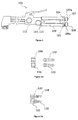
Figure 1 shows an oxy-fuel torch according to the prior art, -
Figures 2A and 2B show connecting means for fluidly connecting the torch ofFigure 1 to gas hoses according to the prior art, -
Figure 3A shows an oxy-fuel torch according to one embodiment of the invention andFigure 3B shows connecting means intended to be connected to the torch ofFigure 3A , and -
Figure 4 shows one embodiment of the handle of the torch shown inFigure 3A . - Refering to
Figure 1 , a conventional oxy-fuel torch 100 comprises ahandle 109 incorporating at least two gas channels (not shown) for feeding at least two gas flows between at least twoinlet ports handle 109. - Two
inlet connectors inlet ports connectors external surface portion 107a, 107b. In general, the inlet connectors are fixed on thehandle 109 by, for example by welding on the handle or part of the handle. - The
inlet connectors inlet port - At least one gas hose is fluidly connected to a fuel gas cylinder at one end and to the
inlet connector 107 at the other hose end so that a flow of fuel gas can be dispensed into theinlet port 104 when operating the torch. - At least one other gas hose is fluidly connected to an oxidizing gas cylinder at one end and to the
inlet connector 108 at the other end so that a flow of oxidizing gas can be dispensed into theinlet port 105 when operating the torch. -
Figures 2A and 2B shows examples of intermediate connection means that are used conventionally in oxy-fuel torches.Coupling nuts inlet connectors hose tails nuts inlet connectors hose tails quick connection nipples inlet connector nuts - Now referring to
Figures 3A and 3B , the oxy-fuel torch 10 according to one embodiment of the invention comprises at least two gas channels extending through thehandle 9 for conveying at least a flow of fuel gas and a flow of oxidizing gas between therespective inlet ports handle 9. - With respect to the present invention an inlet port or an outlet port may be understood as any orifice, or any device or member comprising an orifice, adapted to dispense or receive a fluid flow.
- The
inlet connectors handle 9 and are in fluidic communication with eachinlet inlet connectors inlet port - According to the invention, each
inlet connector respective inlet port torch 10. - The terms "non-threaded" mean that there is no thread provided on the external or internal part of the inlet connectors.
- Permanent connection means that joining is not based on removable fasteners such as nuts or screws. This type of fastening is not supposed to be removed and if removed, may affect the base material of the parts that were connected.
- Owing to the invention, it is possible to manufacture a single type of oxy-fuel torch, having a given type of inlet connectors, which is suitable for all countries. The intermediate connection means 20, 21 can be supplied separatly from the torch and have the features adapted to the country standards of the gas hose connectors. This leads to a decrease in manufacturing costs, as well as a more reliable device thanks to the reduced number of threaded connection interfaces, in comparison with the devices of prior art.
- Each
inlet connector corresponding inlet port - Preferably, the
inlet connectors inlet ports - Advantageously, each
inlet connector corresponding inlet port - Preferably, the intermediate connection means 20, 21 are configured to be mechanically fastened to the inlet connectors at a one end, and are configured to be mechanically fastened to gas hose connectors at another end. These fastening are removable.
- According to a preferred embodiment of the invention, the intermediate connection means 20, 21 comprise
quick connectors inlet connectors male coupling portion female head portion quick connector inlet connectors quick connectors - Advantageously, the corresponding
male coupling portion female head portion - In the particular embodiment illustrated in
Figure 3A , eachmale coupling portion relief Figure 3B ) of thefemale head portion quick connector - More preferably, each
male coupling portion circumferential protusion external protusion 7a, 7b. Saidprotusions female head portion - In a way known per se, the
quick connectors - Advantageously, the
quick connectors terminal portions terminal portions - Advantageously, the threaded portions on the
terminal portions terminal portion 21 b intended to receive the connector of the oxidizing gas hose is right-handed, while theterminal portion 20b intended to receive the connector of the fuel gas hose has a left-handed thread. - Advantageously, the
inlet connectors - The
Figures 3A and4 illustrates a preferred embodiment of atorch handle 9 incorporatinginlet connectors - The
handle 9 extends globally parallel to a longitudinal axis X-X between a front side located on the side of the outlet ports 14, 15 and a back side located on the side of theinlet ports - Advantageously, the
handle 9 comprises aperipheral wall 9a extending globally parallel to the longitudinal axis X-X from its back side, thereby defining a bore wherein theinlet connectors Figure 4 . - In other words, considering the embodiment shown in
Figure 3A , theperipheral wall 9a extend at least beyond the terminal end of theportions inlet connectors - This offers an improved protection of the
inlet connectors - The
peripheral wall 9a may have a globally oblong transverse section. - Preferably, the
peripheral wall 9a is made integral with thehandle 9. This makes thehandle 9 more robust. - The length of the
peripheral wall 9a, measured parallel to the longitudinal axis X-X, may be comprised between 50 and 300 mm, preferably between 100 and 250 mm. The external width of theperipheral wall 9a, measured perpendicular to the longitudinal axis X-X, may be comprised between 30 and 70 mm, preferably between 40 and 60 mm. - The invention is applied advantageously to an oxy-fuel cutting torch. In addition to flow regulation means 12, 13 mounted on the
body 11 of the torch so as to regulate the flow of the fuel gas and/or the flow of the oxidizing gas delivered by the outlet ports 14, 15, the torch comprises additional flow regulation means 16 arranged on thebody 11 so as to regulate an additional stream of a cutting oxidizing gas. - Said additional regulation means may comprise a
lever 16 configured to cooperate with an additonal valve (not shown), saidlever 16 being displaceable between a rest position in which said valve prevents the cutting gas to flow out of thebody 11, and an active position in which at least the valve allows the cutting gas to flow out of thebody 11.
Claims (14)
- Oxy-fuel torch (10) comprising :- a handle (9) by which the torch (10) can be manipulated,- at least two gas channels arranged through said handle (9) for conveying at least a flow of fuel gas and a flow of oxidizing gas between respective inlets ports (4, 5) and outlet ports (14, 15), and- inlet connectors (7, 8) in fluidic communication with each inlet ports (4, 5), the inlet connectors (7, 8) being configured to fluidly connect each inlet port (4, 5) to a corresponding gas hose via intermediate connection means (20, 21),
characterized in that each inlet connector (7, 8) is a non-threaded connector and is permanently connected with each respective inlet port (4, 5). - Torch according to claim 1, characterized in that each inlet connector (7, 8) is joined to each inlet port (4, 5) by brazing.
- Torch according to any of claims 1 or 2, characterized in that the intermediate connection means (20, 21) comprise quick connectors (20, 21), each inlet connectors (7, 8) having a male coupling portion (7a, 8a) configured to cooperate with a female head portion (20a, 21a) of each quick connector (20, 21) in order to retain said inlet connectors (7, 8) and said quick connectors (20, 21) in fastened configuration.
- Torch according to claim 3, characterized in that each male coupling portion (7a, 8a) is provided with at least one element in relief (7a, 7b) adapted to cooperate with a corresponding element in relief of the female head portion (20a, 21a) of each quick connector (20, 21) in order to retain said elements in relief in fitted configuration.
- Torch according to claim 4, characterized in that each male coupling portion (7a, 8a) comprises a tubular member provided with at least one circumferential protusion (7a, 7b) arranged at a predetermined distance (d) from the free end of the tubular member so as to engage at least one bearing of the female head portion (20a, 21 a) of each quick connector (20, 21) with said protrusion (7a, 7b).
- Torch according to any of the preceeding claims, characterized in that the handle (9) extends globally parallel to a longitudinal axis (X-X) between a front side located on the side of the outlet ports (14, 15) and a back side located on the side of the inlet ports (4, 5), the handle (9) comprising a peripheral wall (9a) extending globally parallel to the longitudinal axis (X-X) from its back side, thereby defining a bore wherein the inlet connectors (7, 8) are accommodated completely.
- Torch according to claim 6, characterized in that the peripheral wall (9a) is made integral with the handle (9).
- Torch according to any of claims 6 or 7, characterized in that the length of the peripheral wall (9a), measured parallel to the longitudinal axis (X-X), is comprised between 50 and 300 mm, preferably between 100 and 250 mm.
- Torch according to any of claims 6 to 8, characterized in that the external width of the peripheral wall (9a), measured perpendicular to the longitudinal axis X-X, is comprised between 30 and 70 mm, preferably between 40 and 60 mm.
- Torch according to any of the preceeding claims, characterized in that it comprises a body (11) attached to the front side of the handle (9) and flow regulation means (12, 13) being mounted on the body (11) in fluidic communication with the outlet ports (14, 15) respectively, so as to regulate the flow of the fuel gas and/or the flow of the oxidizing gas delivered by the outlet ports (14, 15) when operating the torch.
- Torch according to claim 10, characterized in that the torch is a cutting torch comprising additional flow regulation means (16) mounted on the body (11) for regulating an additional flow of cutting oxydizing gas.
- Oxy-fuel assembly comprising an oxy-fuel torch (10) according to any of the preceeding claims and intermediate connection means (20, 21) configured to fluidly connect each inlet connectors (7, 8) to a corresponding gas hose.
- Assembly according to claim 12, characterized in that the intermediate connection means (20, 21) comprise quick connectors (20, 21), each quick connector (20, 21) having a female head portion (20a, 21 a) configured to mate with a male coupling portion (7a, 8a) of each inlet connectors (7, 8) and a terminal portion (20b, 21 b) configured to be connected with a hose connector (22, 23) to be attached to a gas hose.
- Method for cutting, welding, brazing or heating at least on metallic workpiece using an assembly according to any of claims 12 or 13, wherein each inlet connectors (7, 8) is fluidly connected to a corresponding gas hose via intermediate connection means (20, 21), and wherein at least a flow of oxidizing gas, in particular oxygen or an oxygen-containing gas, and a flow of fuel gas, in particular acetylene or an hydrocarbon-containing gas, are dispensed in said corresponding hoses.
Priority Applications (9)
| Application Number | Priority Date | Filing Date | Title |
|---|---|---|---|
| ES16425058T ES2807423T3 (en) | 2016-06-17 | 2016-06-17 | Oxy-fuel torch having quick connection means |
| EP16425058.1A EP3258156B1 (en) | 2016-06-17 | 2016-06-17 | Oxy-fuel torch having quick connection means |
| BR112018075599-0A BR112018075599A2 (en) | 2016-06-17 | 2017-05-02 | oxyfuel torch, oxyfuel assembly and method for cutting, welding, brazing or heating at least on a metal part using an assembly |
| PCT/EP2017/060403 WO2017215827A1 (en) | 2016-06-17 | 2017-05-02 | Oxy-fuel torch having quick connection means |
| MX2018015581A MX2018015581A (en) | 2016-06-17 | 2017-05-02 | Oxy-fuel torch having quick connection means. |
| JP2018554357A JP7118008B2 (en) | 2016-06-17 | 2017-05-02 | Oxygen fuel torch with quick connect means |
| CN201780026071.0A CN109073127B (en) | 2016-06-17 | 2017-05-02 | Oxy-fuel torch with quick connect device |
| US16/190,379 US10890324B2 (en) | 2016-06-17 | 2018-11-14 | Oxy-fuel torch having quick connection means |
| JP2022001143A JP7366165B2 (en) | 2016-06-17 | 2022-01-06 | Oxyfuel torch with quick connection means |
Applications Claiming Priority (1)
| Application Number | Priority Date | Filing Date | Title |
|---|---|---|---|
| EP16425058.1A EP3258156B1 (en) | 2016-06-17 | 2016-06-17 | Oxy-fuel torch having quick connection means |
Publications (2)
| Publication Number | Publication Date |
|---|---|
| EP3258156A1 true EP3258156A1 (en) | 2017-12-20 |
| EP3258156B1 EP3258156B1 (en) | 2020-06-10 |
Family
ID=56738059
Family Applications (1)
| Application Number | Title | Priority Date | Filing Date |
|---|---|---|---|
| EP16425058.1A Active EP3258156B1 (en) | 2016-06-17 | 2016-06-17 | Oxy-fuel torch having quick connection means |
Country Status (8)
| Country | Link |
|---|---|
| US (1) | US10890324B2 (en) |
| EP (1) | EP3258156B1 (en) |
| JP (2) | JP7118008B2 (en) |
| CN (1) | CN109073127B (en) |
| BR (1) | BR112018075599A2 (en) |
| ES (1) | ES2807423T3 (en) |
| MX (1) | MX2018015581A (en) |
| WO (1) | WO2017215827A1 (en) |
Families Citing this family (3)
| Publication number | Priority date | Publication date | Assignee | Title |
|---|---|---|---|---|
| JP2778825B2 (en) | 1990-11-28 | 1998-07-23 | 株式会社東芝 | Graphic display device |
| US12168272B2 (en) | 2020-09-18 | 2024-12-17 | Pipeline Supply & Service, Llc | Gasless, mechanized, field-welding of tubular structure |
| US11673204B2 (en) | 2020-11-25 | 2023-06-13 | The Esab Group, Inc. | Hyper-TIG welding electrode |
Citations (5)
| Publication number | Priority date | Publication date | Assignee | Title |
|---|---|---|---|---|
| FR645960A (en) * | 1927-12-20 | 1928-11-06 | Welding torch | |
| US2506114A (en) * | 1947-07-05 | 1950-05-02 | John M Henry | Trigger-type gaseous blowtorch |
| US3679171A (en) * | 1971-01-19 | 1972-07-25 | Frank Baranowski Jr | Torch handle |
| FR2122880A5 (en) * | 1971-01-19 | 1972-09-01 | Messer Griesheim Gmbh | |
| US3761117A (en) * | 1972-04-19 | 1973-09-25 | Crawford Fitting Co | Quick connect fitting |
Family Cites Families (10)
| Publication number | Priority date | Publication date | Assignee | Title |
|---|---|---|---|---|
| FR960E (en) * | 1901-10-30 | 1903-04-29 | Savoye Deglaire & Fils Soc | Improvements to corset and other clothing closures |
| JPS4867152A (en) * | 1971-12-18 | 1973-09-13 | ||
| JPS5330013Y2 (en) * | 1972-03-11 | 1978-07-27 | ||
| JPS60253709A (en) * | 1984-03-26 | 1985-12-14 | ビクター・イクイプメント・カンパニー | Torch with head-mixer |
| US4779608A (en) * | 1986-11-17 | 1988-10-25 | Smith T Randolph | Fireplace starter apparatus |
| JP3072190U (en) | 2000-03-31 | 2000-10-06 | 岩谷産業株式会社 | Tinder attachment for grass burner burner |
| CN202692054U (en) * | 2012-07-04 | 2013-01-23 | 宁波隆兴焊割科技股份有限公司 | Flameout-free efficient temper-resistant cutting torch |
| CN103075732B (en) * | 2012-12-25 | 2015-05-13 | 宁波隆兴焊割科技股份有限公司 | Novel oxyhydrogen flame gun |
| CN104741262B (en) * | 2013-12-27 | 2017-05-24 | 金华市金顺工具有限公司 | Split type handheld spray gun |
| CN105570895A (en) * | 2015-12-30 | 2016-05-11 | 宁波市江北兴达焊割减压仪表厂 | Anti-misoperation welding torch |
-
2016
- 2016-06-17 ES ES16425058T patent/ES2807423T3/en active Active
- 2016-06-17 EP EP16425058.1A patent/EP3258156B1/en active Active
-
2017
- 2017-05-02 BR BR112018075599-0A patent/BR112018075599A2/en not_active Application Discontinuation
- 2017-05-02 JP JP2018554357A patent/JP7118008B2/en active Active
- 2017-05-02 WO PCT/EP2017/060403 patent/WO2017215827A1/en not_active Ceased
- 2017-05-02 CN CN201780026071.0A patent/CN109073127B/en active Active
- 2017-05-02 MX MX2018015581A patent/MX2018015581A/en unknown
-
2018
- 2018-11-14 US US16/190,379 patent/US10890324B2/en active Active
-
2022
- 2022-01-06 JP JP2022001143A patent/JP7366165B2/en active Active
Patent Citations (5)
| Publication number | Priority date | Publication date | Assignee | Title |
|---|---|---|---|---|
| FR645960A (en) * | 1927-12-20 | 1928-11-06 | Welding torch | |
| US2506114A (en) * | 1947-07-05 | 1950-05-02 | John M Henry | Trigger-type gaseous blowtorch |
| US3679171A (en) * | 1971-01-19 | 1972-07-25 | Frank Baranowski Jr | Torch handle |
| FR2122880A5 (en) * | 1971-01-19 | 1972-09-01 | Messer Griesheim Gmbh | |
| US3761117A (en) * | 1972-04-19 | 1973-09-25 | Crawford Fitting Co | Quick connect fitting |
Also Published As
| Publication number | Publication date |
|---|---|
| JP2019523852A (en) | 2019-08-29 |
| US10890324B2 (en) | 2021-01-12 |
| JP2022068876A (en) | 2022-05-10 |
| CN109073127A (en) | 2018-12-21 |
| JP7366165B2 (en) | 2023-10-20 |
| JP7118008B2 (en) | 2022-08-15 |
| ES2807423T3 (en) | 2021-02-23 |
| EP3258156B1 (en) | 2020-06-10 |
| MX2018015581A (en) | 2019-06-06 |
| WO2017215827A1 (en) | 2017-12-21 |
| US20190078778A1 (en) | 2019-03-14 |
| CN109073127B (en) | 2021-03-16 |
| BR112018075599A2 (en) | 2019-03-26 |
Similar Documents
| Publication | Publication Date | Title |
|---|---|---|
| JP7366165B2 (en) | Oxyfuel torch with quick connection means | |
| CN108027097B (en) | Push-in connection fitting assembly and method with guard | |
| US7208699B2 (en) | Spool gun having unitary shielding gas and weld power connector | |
| US9643278B2 (en) | Hose assembly and coupling device for a welding device | |
| EP1988324B1 (en) | Torch or other gas fueled appliance and more particularly a coupling for connecting a fuel canister to a torch head or other appliance | |
| US8338753B2 (en) | Contact tip and diffuser | |
| EP0032151A1 (en) | Cutting torch having integral head mixer | |
| US4409002A (en) | Utility torch having head mixer | |
| CN107466254A (en) | Sprayer Adapter | |
| US6824735B2 (en) | Gas cutting torch | |
| US7038168B2 (en) | Spindle and spool for welding gun | |
| US20160298798A1 (en) | Assembly for Connecting a Tube | |
| US3873028A (en) | Precision torch assembly | |
| JPH07136554A (en) | Screwing-type spraying nozzle and method for mounting it | |
| JP2010078027A5 (en) | ||
| US20090127320A1 (en) | Refrigeration purging adaptor | |
| US20180229325A1 (en) | Tig gun power pin for welding device or system and multi-process welder with a single gas flow path | |
| US7241972B2 (en) | Miniature welding gun | |
| US20190145622A1 (en) | Fuel tip with integrated flashback arrestor | |
| JP2019523852A5 (en) | ||
| US20120217744A1 (en) | Hybrid Tube Connector Port | |
| JPH0342152B2 (en) | ||
| US20230313986A1 (en) | Flexible torch tool and method | |
| JP5889370B1 (en) | Gas cutter crater | |
| JPWO2004112970A1 (en) | Eddy current type liquid atomization nozzle |
Legal Events
| Date | Code | Title | Description |
|---|---|---|---|
| PUAI | Public reference made under article 153(3) epc to a published international application that has entered the european phase |
Free format text: ORIGINAL CODE: 0009012 |
|
| STAA | Information on the status of an ep patent application or granted ep patent |
Free format text: STATUS: THE APPLICATION HAS BEEN PUBLISHED |
|
| AK | Designated contracting states |
Kind code of ref document: A1 Designated state(s): AL AT BE BG CH CY CZ DE DK EE ES FI FR GB GR HR HU IE IS IT LI LT LU LV MC MK MT NL NO PL PT RO RS SE SI SK SM TR |
|
| AX | Request for extension of the european patent |
Extension state: BA ME |
|
| STAA | Information on the status of an ep patent application or granted ep patent |
Free format text: STATUS: REQUEST FOR EXAMINATION WAS MADE |
|
| 17P | Request for examination filed |
Effective date: 20180620 |
|
| RBV | Designated contracting states (corrected) |
Designated state(s): AL AT BE BG CH CY CZ DE DK EE ES FI FR GB GR HR HU IE IS IT LI LT LU LV MC MK MT NL NO PL PT RO RS SE SI SK SM TR |
|
| RAP1 | Party data changed (applicant data changed or rights of an application transferred) |
Owner name: LINCOLN ELECTRIC ITALIA S.R.L. |
|
| GRAP | Despatch of communication of intention to grant a patent |
Free format text: ORIGINAL CODE: EPIDOSNIGR1 |
|
| STAA | Information on the status of an ep patent application or granted ep patent |
Free format text: STATUS: GRANT OF PATENT IS INTENDED |
|
| INTG | Intention to grant announced |
Effective date: 20200115 |
|
| GRAS | Grant fee paid |
Free format text: ORIGINAL CODE: EPIDOSNIGR3 |
|
| GRAA | (expected) grant |
Free format text: ORIGINAL CODE: 0009210 |
|
| STAA | Information on the status of an ep patent application or granted ep patent |
Free format text: STATUS: THE PATENT HAS BEEN GRANTED |
|
| AK | Designated contracting states |
Kind code of ref document: B1 Designated state(s): AL AT BE BG CH CY CZ DE DK EE ES FI FR GB GR HR HU IE IS IT LI LT LU LV MC MK MT NL NO PL PT RO RS SE SI SK SM TR |
|
| REG | Reference to a national code |
Ref country code: GB Ref legal event code: FG4D |
|
| REG | Reference to a national code |
Ref country code: CH Ref legal event code: EP Ref country code: AT Ref legal event code: REF Ref document number: 1279468 Country of ref document: AT Kind code of ref document: T Effective date: 20200615 |
|
| REG | Reference to a national code |
Ref country code: DE Ref legal event code: R096 Ref document number: 602016037829 Country of ref document: DE |
|
| REG | Reference to a national code |
Ref country code: IE Ref legal event code: FG4D |
|
| REG | Reference to a national code |
Ref country code: LT Ref legal event code: MG4D |
|
| PG25 | Lapsed in a contracting state [announced via postgrant information from national office to epo] |
Ref country code: SE Free format text: LAPSE BECAUSE OF FAILURE TO SUBMIT A TRANSLATION OF THE DESCRIPTION OR TO PAY THE FEE WITHIN THE PRESCRIBED TIME-LIMIT Effective date: 20200610 Ref country code: LT Free format text: LAPSE BECAUSE OF FAILURE TO SUBMIT A TRANSLATION OF THE DESCRIPTION OR TO PAY THE FEE WITHIN THE PRESCRIBED TIME-LIMIT Effective date: 20200610 Ref country code: NO Free format text: LAPSE BECAUSE OF FAILURE TO SUBMIT A TRANSLATION OF THE DESCRIPTION OR TO PAY THE FEE WITHIN THE PRESCRIBED TIME-LIMIT Effective date: 20200910 Ref country code: GR Free format text: LAPSE BECAUSE OF FAILURE TO SUBMIT A TRANSLATION OF THE DESCRIPTION OR TO PAY THE FEE WITHIN THE PRESCRIBED TIME-LIMIT Effective date: 20200911 Ref country code: FI Free format text: LAPSE BECAUSE OF FAILURE TO SUBMIT A TRANSLATION OF THE DESCRIPTION OR TO PAY THE FEE WITHIN THE PRESCRIBED TIME-LIMIT Effective date: 20200610 |
|
| REG | Reference to a national code |
Ref country code: NL Ref legal event code: MP Effective date: 20200610 |
|
| PG25 | Lapsed in a contracting state [announced via postgrant information from national office to epo] |
Ref country code: LV Free format text: LAPSE BECAUSE OF FAILURE TO SUBMIT A TRANSLATION OF THE DESCRIPTION OR TO PAY THE FEE WITHIN THE PRESCRIBED TIME-LIMIT Effective date: 20200610 Ref country code: HR Free format text: LAPSE BECAUSE OF FAILURE TO SUBMIT A TRANSLATION OF THE DESCRIPTION OR TO PAY THE FEE WITHIN THE PRESCRIBED TIME-LIMIT Effective date: 20200610 Ref country code: BG Free format text: LAPSE BECAUSE OF FAILURE TO SUBMIT A TRANSLATION OF THE DESCRIPTION OR TO PAY THE FEE WITHIN THE PRESCRIBED TIME-LIMIT Effective date: 20200910 Ref country code: RS Free format text: LAPSE BECAUSE OF FAILURE TO SUBMIT A TRANSLATION OF THE DESCRIPTION OR TO PAY THE FEE WITHIN THE PRESCRIBED TIME-LIMIT Effective date: 20200610 |
|
| REG | Reference to a national code |
Ref country code: AT Ref legal event code: MK05 Ref document number: 1279468 Country of ref document: AT Kind code of ref document: T Effective date: 20200610 |
|
| PG25 | Lapsed in a contracting state [announced via postgrant information from national office to epo] |
Ref country code: AL Free format text: LAPSE BECAUSE OF FAILURE TO SUBMIT A TRANSLATION OF THE DESCRIPTION OR TO PAY THE FEE WITHIN THE PRESCRIBED TIME-LIMIT Effective date: 20200610 Ref country code: NL Free format text: LAPSE BECAUSE OF FAILURE TO SUBMIT A TRANSLATION OF THE DESCRIPTION OR TO PAY THE FEE WITHIN THE PRESCRIBED TIME-LIMIT Effective date: 20200610 |
|
| PG25 | Lapsed in a contracting state [announced via postgrant information from national office to epo] |
Ref country code: RO Free format text: LAPSE BECAUSE OF FAILURE TO SUBMIT A TRANSLATION OF THE DESCRIPTION OR TO PAY THE FEE WITHIN THE PRESCRIBED TIME-LIMIT Effective date: 20200610 Ref country code: CZ Free format text: LAPSE BECAUSE OF FAILURE TO SUBMIT A TRANSLATION OF THE DESCRIPTION OR TO PAY THE FEE WITHIN THE PRESCRIBED TIME-LIMIT Effective date: 20200610 Ref country code: PT Free format text: LAPSE BECAUSE OF FAILURE TO SUBMIT A TRANSLATION OF THE DESCRIPTION OR TO PAY THE FEE WITHIN THE PRESCRIBED TIME-LIMIT Effective date: 20201012 Ref country code: AT Free format text: LAPSE BECAUSE OF FAILURE TO SUBMIT A TRANSLATION OF THE DESCRIPTION OR TO PAY THE FEE WITHIN THE PRESCRIBED TIME-LIMIT Effective date: 20200610 Ref country code: SM Free format text: LAPSE BECAUSE OF FAILURE TO SUBMIT A TRANSLATION OF THE DESCRIPTION OR TO PAY THE FEE WITHIN THE PRESCRIBED TIME-LIMIT Effective date: 20200610 Ref country code: EE Free format text: LAPSE BECAUSE OF FAILURE TO SUBMIT A TRANSLATION OF THE DESCRIPTION OR TO PAY THE FEE WITHIN THE PRESCRIBED TIME-LIMIT Effective date: 20200610 |
|
| REG | Reference to a national code |
Ref country code: CH Ref legal event code: PL |
|
| REG | Reference to a national code |
Ref country code: ES Ref legal event code: FG2A Ref document number: 2807423 Country of ref document: ES Kind code of ref document: T3 Effective date: 20210223 |
|
| PG25 | Lapsed in a contracting state [announced via postgrant information from national office to epo] |
Ref country code: SK Free format text: LAPSE BECAUSE OF FAILURE TO SUBMIT A TRANSLATION OF THE DESCRIPTION OR TO PAY THE FEE WITHIN THE PRESCRIBED TIME-LIMIT Effective date: 20200610 Ref country code: PL Free format text: LAPSE BECAUSE OF FAILURE TO SUBMIT A TRANSLATION OF THE DESCRIPTION OR TO PAY THE FEE WITHIN THE PRESCRIBED TIME-LIMIT Effective date: 20200610 Ref country code: IS Free format text: LAPSE BECAUSE OF FAILURE TO SUBMIT A TRANSLATION OF THE DESCRIPTION OR TO PAY THE FEE WITHIN THE PRESCRIBED TIME-LIMIT Effective date: 20201010 |
|
| REG | Reference to a national code |
Ref country code: DE Ref legal event code: R097 Ref document number: 602016037829 Country of ref document: DE |
|
| PG25 | Lapsed in a contracting state [announced via postgrant information from national office to epo] |
Ref country code: LU Free format text: LAPSE BECAUSE OF NON-PAYMENT OF DUE FEES Effective date: 20200617 Ref country code: MC Free format text: LAPSE BECAUSE OF FAILURE TO SUBMIT A TRANSLATION OF THE DESCRIPTION OR TO PAY THE FEE WITHIN THE PRESCRIBED TIME-LIMIT Effective date: 20200610 |
|
| PLBE | No opposition filed within time limit |
Free format text: ORIGINAL CODE: 0009261 |
|
| STAA | Information on the status of an ep patent application or granted ep patent |
Free format text: STATUS: NO OPPOSITION FILED WITHIN TIME LIMIT |
|
| REG | Reference to a national code |
Ref country code: BE Ref legal event code: MM Effective date: 20200630 |
|
| PG25 | Lapsed in a contracting state [announced via postgrant information from national office to epo] |
Ref country code: IE Free format text: LAPSE BECAUSE OF NON-PAYMENT OF DUE FEES Effective date: 20200617 Ref country code: LI Free format text: LAPSE BECAUSE OF NON-PAYMENT OF DUE FEES Effective date: 20200630 Ref country code: DK Free format text: LAPSE BECAUSE OF FAILURE TO SUBMIT A TRANSLATION OF THE DESCRIPTION OR TO PAY THE FEE WITHIN THE PRESCRIBED TIME-LIMIT Effective date: 20200610 Ref country code: CH Free format text: LAPSE BECAUSE OF NON-PAYMENT OF DUE FEES Effective date: 20200630 |
|
| 26N | No opposition filed |
Effective date: 20210311 |
|
| GBPC | Gb: european patent ceased through non-payment of renewal fee |
Effective date: 20200910 |
|
| PG25 | Lapsed in a contracting state [announced via postgrant information from national office to epo] |
Ref country code: BE Free format text: LAPSE BECAUSE OF NON-PAYMENT OF DUE FEES Effective date: 20200630 Ref country code: SI Free format text: LAPSE BECAUSE OF FAILURE TO SUBMIT A TRANSLATION OF THE DESCRIPTION OR TO PAY THE FEE WITHIN THE PRESCRIBED TIME-LIMIT Effective date: 20200610 |
|
| PG25 | Lapsed in a contracting state [announced via postgrant information from national office to epo] |
Ref country code: GB Free format text: LAPSE BECAUSE OF NON-PAYMENT OF DUE FEES Effective date: 20200910 |
|
| PG25 | Lapsed in a contracting state [announced via postgrant information from national office to epo] |
Ref country code: MT Free format text: LAPSE BECAUSE OF FAILURE TO SUBMIT A TRANSLATION OF THE DESCRIPTION OR TO PAY THE FEE WITHIN THE PRESCRIBED TIME-LIMIT Effective date: 20200610 Ref country code: CY Free format text: LAPSE BECAUSE OF FAILURE TO SUBMIT A TRANSLATION OF THE DESCRIPTION OR TO PAY THE FEE WITHIN THE PRESCRIBED TIME-LIMIT Effective date: 20200610 |
|
| PG25 | Lapsed in a contracting state [announced via postgrant information from national office to epo] |
Ref country code: MK Free format text: LAPSE BECAUSE OF FAILURE TO SUBMIT A TRANSLATION OF THE DESCRIPTION OR TO PAY THE FEE WITHIN THE PRESCRIBED TIME-LIMIT Effective date: 20200610 |
|
| PGFP | Annual fee paid to national office [announced via postgrant information from national office to epo] |
Ref country code: DE Payment date: 20250618 Year of fee payment: 10 |
|
| PGFP | Annual fee paid to national office [announced via postgrant information from national office to epo] |
Ref country code: FR Payment date: 20250623 Year of fee payment: 10 |
|
| PGFP | Annual fee paid to national office [announced via postgrant information from national office to epo] |
Ref country code: TR Payment date: 20250613 Year of fee payment: 10 |
|
| PGFP | Annual fee paid to national office [announced via postgrant information from national office to epo] |
Ref country code: ES Payment date: 20250718 Year of fee payment: 10 |
|
| PGFP | Annual fee paid to national office [announced via postgrant information from national office to epo] |
Ref country code: IT Payment date: 20250630 Year of fee payment: 10 |