EP3258108A1 - Head fastening arrangement of cooling compressor - Google Patents
Head fastening arrangement of cooling compressor Download PDFInfo
- Publication number
- EP3258108A1 EP3258108A1 EP17174777.7A EP17174777A EP3258108A1 EP 3258108 A1 EP3258108 A1 EP 3258108A1 EP 17174777 A EP17174777 A EP 17174777A EP 3258108 A1 EP3258108 A1 EP 3258108A1
- Authority
- EP
- European Patent Office
- Prior art keywords
- supporting device
- head
- cylinder
- arrangement
- fact
- Prior art date
- Legal status (The legal status is an assumption and is not a legal conclusion. Google has not performed a legal analysis and makes no representation as to the accuracy of the status listed.)
- Granted
Links
Images



Classifications
-
- F—MECHANICAL ENGINEERING; LIGHTING; HEATING; WEAPONS; BLASTING
- F04—POSITIVE - DISPLACEMENT MACHINES FOR LIQUIDS; PUMPS FOR LIQUIDS OR ELASTIC FLUIDS
- F04B—POSITIVE-DISPLACEMENT MACHINES FOR LIQUIDS; PUMPS
- F04B39/00—Component parts, details, or accessories, of pumps or pumping systems specially adapted for elastic fluids, not otherwise provided for in, or of interest apart from, groups F04B25/00 - F04B37/00
- F04B39/12—Casings; Cylinders; Cylinder heads; Fluid connections
-
- F—MECHANICAL ENGINEERING; LIGHTING; HEATING; WEAPONS; BLASTING
- F04—POSITIVE - DISPLACEMENT MACHINES FOR LIQUIDS; PUMPS FOR LIQUIDS OR ELASTIC FLUIDS
- F04B—POSITIVE-DISPLACEMENT MACHINES FOR LIQUIDS; PUMPS
- F04B39/00—Component parts, details, or accessories, of pumps or pumping systems specially adapted for elastic fluids, not otherwise provided for in, or of interest apart from, groups F04B25/00 - F04B37/00
- F04B39/12—Casings; Cylinders; Cylinder heads; Fluid connections
- F04B39/127—Mounting of a cylinder block in a casing
-
- F—MECHANICAL ENGINEERING; LIGHTING; HEATING; WEAPONS; BLASTING
- F04—POSITIVE - DISPLACEMENT MACHINES FOR LIQUIDS; PUMPS FOR LIQUIDS OR ELASTIC FLUIDS
- F04B—POSITIVE-DISPLACEMENT MACHINES FOR LIQUIDS; PUMPS
- F04B53/00—Component parts, details or accessories not provided for in, or of interest apart from, groups F04B1/00 - F04B23/00 or F04B39/00 - F04B47/00
- F04B53/007—Cylinder heads
-
- F—MECHANICAL ENGINEERING; LIGHTING; HEATING; WEAPONS; BLASTING
- F04—POSITIVE - DISPLACEMENT MACHINES FOR LIQUIDS; PUMPS FOR LIQUIDS OR ELASTIC FLUIDS
- F04B—POSITIVE-DISPLACEMENT MACHINES FOR LIQUIDS; PUMPS
- F04B39/00—Component parts, details, or accessories, of pumps or pumping systems specially adapted for elastic fluids, not otherwise provided for in, or of interest apart from, groups F04B25/00 - F04B37/00
- F04B39/12—Casings; Cylinders; Cylinder heads; Fluid connections
- F04B39/122—Cylinder block
-
- F—MECHANICAL ENGINEERING; LIGHTING; HEATING; WEAPONS; BLASTING
- F04—POSITIVE - DISPLACEMENT MACHINES FOR LIQUIDS; PUMPS FOR LIQUIDS OR ELASTIC FLUIDS
- F04B—POSITIVE-DISPLACEMENT MACHINES FOR LIQUIDS; PUMPS
- F04B39/00—Component parts, details, or accessories, of pumps or pumping systems specially adapted for elastic fluids, not otherwise provided for in, or of interest apart from, groups F04B25/00 - F04B37/00
- F04B39/12—Casings; Cylinders; Cylinder heads; Fluid connections
- F04B39/125—Cylinder heads
-
- F—MECHANICAL ENGINEERING; LIGHTING; HEATING; WEAPONS; BLASTING
- F04—POSITIVE - DISPLACEMENT MACHINES FOR LIQUIDS; PUMPS FOR LIQUIDS OR ELASTIC FLUIDS
- F04B—POSITIVE-DISPLACEMENT MACHINES FOR LIQUIDS; PUMPS
- F04B39/00—Component parts, details, or accessories, of pumps or pumping systems specially adapted for elastic fluids, not otherwise provided for in, or of interest apart from, groups F04B25/00 - F04B37/00
- F04B39/14—Provisions for readily assembling or disassembling
-
- F—MECHANICAL ENGINEERING; LIGHTING; HEATING; WEAPONS; BLASTING
- F04—POSITIVE - DISPLACEMENT MACHINES FOR LIQUIDS; PUMPS FOR LIQUIDS OR ELASTIC FLUIDS
- F04B—POSITIVE-DISPLACEMENT MACHINES FOR LIQUIDS; PUMPS
- F04B53/00—Component parts, details or accessories not provided for in, or of interest apart from, groups F04B1/00 - F04B23/00 or F04B39/00 - F04B47/00
- F04B53/14—Pistons, piston-rods or piston-rod connections
-
- F—MECHANICAL ENGINEERING; LIGHTING; HEATING; WEAPONS; BLASTING
- F04—POSITIVE - DISPLACEMENT MACHINES FOR LIQUIDS; PUMPS FOR LIQUIDS OR ELASTIC FLUIDS
- F04B—POSITIVE-DISPLACEMENT MACHINES FOR LIQUIDS; PUMPS
- F04B53/00—Component parts, details or accessories not provided for in, or of interest apart from, groups F04B1/00 - F04B23/00 or F04B39/00 - F04B47/00
- F04B53/16—Casings; Cylinders; Cylinder liners or heads; Fluid connections
- F04B53/162—Adaptations of cylinders
-
- F—MECHANICAL ENGINEERING; LIGHTING; HEATING; WEAPONS; BLASTING
- F15—FLUID-PRESSURE ACTUATORS; HYDRAULICS OR PNEUMATICS IN GENERAL
- F15B—SYSTEMS ACTING BY MEANS OF FLUIDS IN GENERAL; FLUID-PRESSURE ACTUATORS, e.g. SERVOMOTORS; DETAILS OF FLUID-PRESSURE SYSTEMS, NOT OTHERWISE PROVIDED FOR
- F15B15/00—Fluid-actuated devices for displacing a member from one position to another; Gearing associated therewith
- F15B15/08—Characterised by the construction of the motor unit
- F15B15/14—Characterised by the construction of the motor unit of the straight-cylinder type
- F15B15/1423—Component parts; Constructional details
- F15B15/1438—Cylinder to end cap assemblies
Definitions
- the present invention refers to a new constructive arrangement for fastening the head to the block (and, more precisely, to the cylinder) of a cooling compressor.
- the object of the present invention discloses a solution developed to increase the fastening efficiency of the head and reduce the manufacturing costs of the components.
- the fastening of the head to the compressor block and, more precisely, to the cylinder faces some challenges inherent to the functioning of the compressor. Among these challenges to be overcome are the sealing of the gaskets between the cylinder and the parts that compose the head and also the deformation of the cylinder wall resulting from the transfer of the fastening forces of the head.
- the conventional way for fastening the head to the cylinder involves making indexing holes, by which normally four screws pass through that align the set present on the head (valve, valve plates and the head lid) to the holes located around the wall of the cylinder block.
- indexing holes by which normally four screws pass through that align the set present on the head (valve, valve plates and the head lid) to the holes located around the wall of the cylinder block.
- the state of the art still lacks a head fastening solution for refrigeration compressors that presents low manufacturing complexity and low cost, without further resulting in a decrease of the efficiency of fastening and collateral damage, such as, for example, the increase of deformations on the cylinder wall of the block.
- the present invention basically aims to solve the problem of high complexity of the head fastening solutions and consequently, of the high manufacturing costs, for the current existing refrigeration compressors.
- a head fastening arrangement of cooling compressor comprising: a head arranged by the cylinder of the hermetic compressor having a lid; at least one supporting device also arranged by the cylinder; and at least one element of union of the head lid to the supporting device, being the element of union capable of transmitting force that presses the head lid and the supporting device against the cylinder.
- the fastening arrangement of the present invention is preferably applied in refrigeration compressors, such as, for example, those used in household and commercial refrigeration systems.
- refrigeration compressors such as, for example, those used in household and commercial refrigeration systems.
- the present invention does not restrict itself to such application; it is only one of the possibilities that fall within the scope of the claims.
- the fastening arrangement of the present invention comprises a head arranged by the cylinder 3 of the compressor.
- the head presents a lid 2.
- the lid 2 which is also known as “cylinder lid” here will be called head lid 2, since it encompasses the head components.
- this small nomenclature difference cannot be seen as diminishing or harming the understanding of the scope of protection of the present invention.
- the fastening arrangement 1 of the present invention also comprises at least one supporting device 4 also arranged by the cylinder 3.
- the supporting device 4 is arranged in an opposite position in relation to the head and, consequently, to the head lid 2.
- the arrangement 1 can be accomplished with more than one supporting device 4.
- the supporting device 4 is arranged by the rear 14 of the cylinder 3 and the head is arranged by the front of the cylinder 3.
- the said supporting device 4 can be arranged by the intermediate region of the cylinder 3.
- the supporting device 4 comprises a substantially arched format or, in other words, a "horseshoe" format.
- This particular arched format counts with two end zones 11 A and 11 B and a retreated zone 11C arranged between the end zones 11 A and 11 B.
- the supporting device 4 comprises spare contract regions 10A, 10B, 10C and 10D arranged on its surface 9 facing the cylinder 3. More precisely, the supporting device 4 comprises four spare contact regions, 10B, 10C and 10D, wherein a first 10A and a second 10B spare contact regions are arranged, respectively, at a first end zone 11 A and at a second end zone 11 B of the arched body of the supporting device 4.
- a third and fourth spare contact regions 10C and 10D are arranged at the retreated zone 12 of the arched body of the supporting device 4.
- the retreated zone 12 additionally comprises a rigidity segment 13, which is also spared in relation to the surface 9.
- the function of such segment 13 is precisely to implement the rigidity of the supporting device 4, as its own name already says.
- such segment 13 comprises an arc format and is arranged between the third and fourth contact regions 10C and 10D, being connected to both.
- spare contact regions 10A, 10B, 10C and 10D can present any format within the scope of the invention.
- these contact regions 10A, 10B, 10C and 10D are illustrated as substantially circular rebounds, however, other forms can be adopted, since the figures represent only one of the various possibilities for implementing the invention.
- the fastening arrangement 1 of the present invention additionally comprises at least one element of union 6 of the head lid 2 to at least one supporting device 4, being the element of union 6 capable of transmitting force that presses the head lid 2 and the supporting device 4 against the cylinder 3.
- the element of union 6 is a screw associated with at least one thread arranged on the supporting device 4.
- the element of union 6 may be another piece, arrangement or mechanism that exerts the function of pressing the supporting device 4 and the head lid 2 against the cylinder 3 and may also be or not be associated with a nut or thread.
- the term “thread” mentioned herein also covers equivalent parts, such as nut or any other one that can be used by a screw to perform the functions described herein.
- the element of union 6 is a screw associated with at least one thread provided in the supporting device 4, wherein the head lid 2 has at least one perforated projecting tab 15.
- This perforated projecting tab 15 extends beyond the diameter of the cylinder, as it can be noted from Figures 1 , 4 and 5 .
- the head lid 2 comprises at least two projecting tabs 15 and, even more particularly, the lid 2 comprises two projecting tabs 15, located in opposite positions in relation to each other.
- the supporting device 4 is endowed with at least one fastening hole 8, wherein in the embodiment illustrated in Figure 2 , the supporting device 4 comprises two fastening holes 8 located in opposite positions to each other. From this construction, perforated projecting tabs 15 and the fastening holes 8 are aligned to each other, so that the screw is configured to traverse the fastening hole 8 and the drilling of said projecting tab 15. In this way, the supporting device 4 and the lid 2 are united, so as to have transmission of a force that will press them against the cylinder 3, as already said, and consequently, also pressing them against each other. As for fastening of the screw in this embodiment of the invention, one or more threads can be provided by the fastening hole 8 of the supporting device 4.
- the fastening arrangement 1 of the present invention it is possible to fasten the head to the compressor block more efficiently, using fewer components, and without diminishing the quality of the fastening.
- the spare contact regions 10A, 10B, 10C and 10D which make the present invention even better. These regions are those that effectively touch the cylinder 3 on its rear 14, as it can be seen in Figure 3 .
- the spare contract regions 10A, 10B, 10C and 10D it is transmitted the fastening force in cooperation with the element of union 6 (and its possible additional components, such as threads, for example) only at specific points, which significantly decreases the transfer of moments to the cylinder.
- the present invention fully solves the problems of the state of the art, providing a more efficient fastening solution and allowing the number of components to be decreased.
Landscapes
- Engineering & Computer Science (AREA)
- Mechanical Engineering (AREA)
- General Engineering & Computer Science (AREA)
- Physics & Mathematics (AREA)
- Fluid Mechanics (AREA)
- Compressor (AREA)
Abstract
Description
- The present invention refers to a new constructive arrangement for fastening the head to the block (and, more precisely, to the cylinder) of a cooling compressor. The object of the present invention discloses a solution developed to increase the fastening efficiency of the head and reduce the manufacturing costs of the components.
- The fastening of the head to the compressor block and, more precisely, to the cylinder, faces some challenges inherent to the functioning of the compressor. Among these challenges to be overcome are the sealing of the gaskets between the cylinder and the parts that compose the head and also the deformation of the cylinder wall resulting from the transfer of the fastening forces of the head.
- Nowadays, the conventional way for fastening the head to the cylinder involves making indexing holes, by which normally four screws pass through that align the set present on the head (valve, valve plates and the head lid) to the holes located around the wall of the cylinder block. An example of this conventional way is illustrated in
Figure 9 . - This conventional way presents some drawbacks. Firstly, it is necessary to apply high fastening forces over the screws so that it is possible to guarantee the gaskets sealing, since the contact pressure is more concentrated at the region around the screws, where there is no need to be sealed. These high fastening forces end up generating deformations that are transferred to the cylinder wall. Secondly, there must be holes in all the head components, and mainly threaded holes at the cylinder block, wherein such holes require high precision of position tolerances and high machining time, which, without doubt, significantly raises the cost of such solution.
- In relation to the patent documents, the above mentioned way of fastening using screws can be found, for example, in the document
US 9,074,591 - Another example can be checked on the document
KR 2001054069 - As noted, the state of the art still lacks a head fastening solution for refrigeration compressors that presents low manufacturing complexity and low cost, without further resulting in a decrease of the efficiency of fastening and collateral damage, such as, for example, the increase of deformations on the cylinder wall of the block.
- Therefore, the present invention basically aims to solve the problem of high complexity of the head fastening solutions and consequently, of the high manufacturing costs, for the current existing refrigeration compressors.
- It is also one of the objectives of the present invention to minimize the deformations arising from the transfer of the head fastening forces to the cylinder wall by a fastening arrangement, which ensures the sealing between the head and cylinder gaskets.
- The objectives of the present invention are achieved by means of a head fastening arrangement of cooling compressor comprising: a head arranged by the cylinder of the hermetic compressor having a lid; at least one supporting device also arranged by the cylinder; and at least one element of union of the head lid to the supporting device, being the element of union capable of transmitting force that presses the head lid and the supporting device against the cylinder.
- The present invention will be described in detail on the basis of the following figures, in which:
-
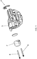
Figure 1 is an exploded perspective view of the head fastening arrangement of the present invention; it is a perspective view of an inner part of a hermetic compressor and, more precisely, its superior part where the head, cylinder, piston, connecting rod, among other components known by a person skilled in the art are located; -
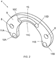
Figure 2 is a perspective view of the supporting apparatus of the present invention; -
Figure 3 is a side cross-sectional view of the cylinder of a hermetic compressor comprising the apparatus of the present invention; -
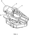
Figure 4 is a perspective view of the apparatus of the present invention; -
Figure 5 is a superior view of the apparatus of the present invention; -
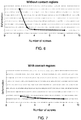
Figure 6 shows a graph of the deformation as a function of the number of screws in the conventional fastening solution; -
Figure 7 shows a graph of the deformation as a function of the number of screws according to the apparatus of the present invention; -
Figure 8 shows top outlined sectional view, in which it is illustrated, in a purposely exaggerated manner, the deformations to which the supporting device shown inFigure 2 is subjected to; and -
Figure 9 illustrates the conventional solution of the state of the art. - The object of the present invention will be further described in detail and explained on the basis of the attached drawings, which merely present illustrative and non-limiting character, since adjustments and modifications can be made without, with this, evading the scope of the claimed protection.
- The fastening arrangement of the present invention is preferably applied in refrigeration compressors, such as, for example, those used in household and commercial refrigeration systems. Evidently, the present invention does not restrict itself to such application; it is only one of the possibilities that fall within the scope of the claims.
- As it is noted from
Figures 1 ,3 ,4 and5 , the fastening arrangement of the present invention comprises a head arranged by thecylinder 3 of the compressor. The head presents alid 2. By the way, thelid 2, which is also known as "cylinder lid" here will be calledhead lid 2, since it encompasses the head components. However, in any way this small nomenclature difference cannot be seen as diminishing or harming the understanding of the scope of protection of the present invention. - Furthermore, the
fastening arrangement 1 of the present invention also comprises at least one supportingdevice 4 also arranged by thecylinder 3. In an embodiment of the present invention, the supportingdevice 4 is arranged in an opposite position in relation to the head and, consequently, to thehead lid 2. Moreover, within the scope of the present invention, thearrangement 1 can be accomplished with more than one supportingdevice 4. In the exemplified embodiment of the invention illustrated inFigures 1 ,3 ,4 and5 , the supportingdevice 4 is arranged by the rear 14 of thecylinder 3 and the head is arranged by the front of thecylinder 3. In other configurations of the present invention, the said supportingdevice 4 can be arranged by the intermediate region of thecylinder 3. Obviously, the "front" and "rear" terms herein have the character of assigning a minimal spatial reference to the reader and, thus, should not be taken to a strictly literal interpretation. - Making now reference to the
Figure 2 , it is possible to see that the supportingdevice 4 comprises a substantially arched format or, in other words, a "horseshoe" format. This particular arched format counts with twoend zones zone 11C arranged between theend zones 11 A and 11 B. Furthermore, the supportingdevice 4 comprisesspare contract regions surface 9 facing thecylinder 3. More precisely, the supportingdevice 4 comprises four spare contact regions, 10B, 10C and 10D, wherein a first 10A and a second 10B spare contact regions are arranged, respectively, at afirst end zone 11 A and at asecond end zone 11 B of the arched body of the supportingdevice 4. Moreover, a third and fourthspare contact regions device 4. - In addition to the
contact regions rigidity segment 13, which is also spared in relation to thesurface 9. Wherein the function ofsuch segment 13 is precisely to implement the rigidity of the supportingdevice 4, as its own name already says. In the example of the embodiment of the invention illustrated in the figures,such segment 13 comprises an arc format and is arranged between the third andfourth contact regions - Additionally, it is worth to highlight herein that the
spare contact regions contact regions - The
fastening arrangement 1 of the present invention additionally comprises at least one element ofunion 6 of thehead lid 2 to at least one supportingdevice 4, being the element ofunion 6 capable of transmitting force that presses thehead lid 2 and the supportingdevice 4 against thecylinder 3. In an embodiment of the present invention, the element ofunion 6 is a screw associated with at least one thread arranged on the supportingdevice 4. In other embodiments of the invention, the element ofunion 6 may be another piece, arrangement or mechanism that exerts the function of pressing the supportingdevice 4 and thehead lid 2 against thecylinder 3 and may also be or not be associated with a nut or thread. By the way, the term "thread" mentioned herein also covers equivalent parts, such as nut or any other one that can be used by a screw to perform the functions described herein. - In the embodiment of the invention the element of
union 6 is a screw associated with at least one thread provided in the supportingdevice 4, wherein thehead lid 2 has at least oneperforated projecting tab 15. Thisperforated projecting tab 15 extends beyond the diameter of the cylinder, as it can be noted fromFigures 1 ,4 and5 . Particularly, thehead lid 2 comprises at least twoprojecting tabs 15 and, even more particularly, thelid 2 comprises two projectingtabs 15, located in opposite positions in relation to each other. - On the other hand, the supporting
device 4 is endowed with at least onefastening hole 8, wherein in the embodiment illustrated inFigure 2 , the supportingdevice 4 comprises twofastening holes 8 located in opposite positions to each other. From this construction, perforated projectingtabs 15 and the fastening holes 8 are aligned to each other, so that the screw is configured to traverse thefastening hole 8 and the drilling of said projectingtab 15. In this way, the supportingdevice 4 and thelid 2 are united, so as to have transmission of a force that will press them against thecylinder 3, as already said, and consequently, also pressing them against each other. As for fastening of the screw in this embodiment of the invention, one or more threads can be provided by thefastening hole 8 of the supportingdevice 4. - From the above described construction of the
fastening arrangement 1 of the present invention, it is possible to fasten the head to the compressor block more efficiently, using fewer components, and without diminishing the quality of the fastening. In addition to these advantages, it is worth mentioning thespare contact regions cylinder 3 on its rear 14, as it can be seen inFigure 3 . Thus, when concentrating the physical contact with thecylinder 3 at thespare contract regions spare contact regions surface 9 would be in contact with thecylinder 3, which would greatly increase the transferred moments. The effect of thecontact regions Figure 8 , which schematically shows the action of moments. - Consequently, when implementing the
contact regions Figure 6 . Such figure, in addition to demonstrating how much the deformation varies depending on the number of screws in the conventional solution of the state of the art, it also shows what occurs in cases where the supportingdevice 4 is employed without thespare contact regions - On the other hand, from the
fastening arrangement 1 of the present invention, it is possible not only to achieve adequate fastening, but also decrease costs in function of the significant reduction of the block machining areas and the contour perimeter of the head components, in addition to the possibility of reducing the number of screws maintaining the deformation of the cylinder wall at appropriate levels. This behavior is illustrated inFigure 7 . - As noted, the present invention fully solves the problems of the state of the art, providing a more efficient fastening solution and allowing the number of components to be decreased.
Claims (10)
- HEAD FASTENING ARRANGEMENT OF COOLING COMPRESSOR comprising:a head arranged by the cylinder (3) of the cooling compressor and having a head lid (2), CHARACTERIZED by the fact that it further comprises:at least one supporting device (4) also arranged by the cylinder (3);at least one element of union (6) of the head lid (2) to the supporting device (4), wherein the element of union (6) is capable of transmitting force that presses the head lid (2) and the supporting device (4) against the cylinder (3).
- ARRANGEMENT, according to claim 1, CHARACTERIZED by the fact that the supporting device (4) is arranged at an opposite position to the head and comprises spare contact regions (10A, 10B, 10C, 10D) arranged on its surface (9) faced to the cylinder.
- ARRANGEMENT, according to claim 2, CHARACTERIZED by the fact that the supporting device (4) comprises at least four spare contact regions (10A, 10B, 10C, 10D).
- ARRANGEMENT, according to claim 1, CHARACTERIZED by the fact that the supporting device (4) comprises an arched format.
- ARRANGEMENT, according to claims 3 and 4, CHARACTERIZED by the fact that a first (10A) and a second (10B) spared contact region are arranged, respectively, in a first end zone (11A) and in a second end zone (11 B) of the arched body of the supporting device (4), further wherein a third and fourth contact regions (10C, 10D) are arranged in an retreated area (12) of the arched body of the supporting device (4).
- ARRANGEMENT, according to claim 5, CHARACTERIZED by the fact that in the retreated area (12) of the arched body of the supporting device (4) it is also provided with a rigidity segment (13), which comprises an arc format and is arranged between the third and fourth contact regions (10C, 10D), being connected to both.
- ARRANGEMENT, according to claim 1, CHARACTERIZED by the fact that the head is arranged at the front of the cylinder (3) and the supporting device (4) is arranged at the rear part (14) of the cylinder (3).
- ARRANGEMENT, according to claim 1, CHARACTERIZED by the fact that the element of union (6) is a screw associated with at least one thread, wherein the head lid (2) is endowed with at least one perforated projecting flap (15) and the supporting device (4) is endowed at least one fastening hole (8), further wherein the screw is configured to traverse the said fastening hole (8) and the perforation of the said projecting flap (15).
- ARRANGEMENT, according to claim 8, CHARACTERIZED by the fact that it comprises two screws, each one associated with at least one thread provided by the fastening hole (8) of the supporting device (4).
- ARRANGEMENT, according to claim 8, characterized by the fact that the supporting device (4) comprises at least two fastening holes (8) located in opposite positions to each other; the head lid (2) comprises at least two perforated projecting tabs (15) located in opposite positions to each other; being the perforated projecting tabs (15) and the fastening holes (8) aligned one in relation to other.
Applications Claiming Priority (1)
| Application Number | Priority Date | Filing Date | Title |
|---|---|---|---|
| BR102016013780A BR102016013780B8 (en) | 2016-06-14 | 2016-06-14 | refrigeration compressor head fixing arrangement |
Publications (2)
| Publication Number | Publication Date |
|---|---|
| EP3258108A1 true EP3258108A1 (en) | 2017-12-20 |
| EP3258108B1 EP3258108B1 (en) | 2022-08-17 |
Family
ID=59053947
Family Applications (1)
| Application Number | Title | Priority Date | Filing Date |
|---|---|---|---|
| EP17174777.7A Active EP3258108B1 (en) | 2016-06-14 | 2017-06-07 | Head fastening arrangement of cooling compressor |
Country Status (5)
| Country | Link |
|---|---|
| US (1) | US10400763B2 (en) |
| EP (1) | EP3258108B1 (en) |
| JP (1) | JP7023622B2 (en) |
| CN (1) | CN107503913B (en) |
| BR (1) | BR102016013780B8 (en) |
Families Citing this family (3)
| Publication number | Priority date | Publication date | Assignee | Title |
|---|---|---|---|---|
| CN111287946B (en) * | 2018-12-10 | 2022-02-11 | 安徽美芝制冷设备有限公司 | Cylinders, reciprocating compressors and refrigerators |
| TR202016945A2 (en) | 2020-10-23 | 2022-05-23 | Arcelik As | COMPRESSOR WITH IMPROVED MOUNTING METHOD AND FIXING METHOD THAT PROVIDES |
| DE102021205681A1 (en) * | 2021-06-04 | 2022-12-08 | Continental Reifen Deutschland Gmbh | Compressor system for a breakdown kit, breakdown kit with such a compressor system and method for sealing a vehicle tire with such a compressor system |
Citations (4)
| Publication number | Priority date | Publication date | Assignee | Title |
|---|---|---|---|---|
| KR20010054069A (en) | 1999-12-03 | 2001-07-02 | 구자홍 | Valve and Headcover assembly for hermetic compressor |
| US20120090461A1 (en) * | 2010-10-14 | 2012-04-19 | Panasonic Corporation | Compressor |
| JP2013221450A (en) * | 2012-04-17 | 2013-10-28 | Calsonic Kansei Corp | Gas compressor |
| US20140020554A1 (en) * | 2012-07-19 | 2014-01-23 | Wei-Chi Wang | Air Pump Cylinder |
Family Cites Families (6)
| Publication number | Priority date | Publication date | Assignee | Title |
|---|---|---|---|---|
| US2148639A (en) * | 1934-11-05 | 1939-02-28 | Maschf Augsburg Nuernberg Ag | Engine frame |
| JPS5842379U (en) * | 1981-09-17 | 1983-03-22 | 三洋電機株式会社 | reciprocating compressor |
| JPS62176491U (en) * | 1986-04-28 | 1987-11-09 | ||
| JPH11303743A (en) * | 1998-04-20 | 1999-11-02 | Matsushita Refrig Co Ltd | Sealed motor-driven compressor |
| JP4499550B2 (en) * | 2004-12-27 | 2010-07-07 | 株式会社日立製作所 | Reciprocating compressor |
| RU2645896C9 (en) * | 2011-09-08 | 2018-07-05 | Биэс Энд Би Сейфити Системз Лимитед | Safety head |
-
2016
- 2016-06-14 BR BR102016013780A patent/BR102016013780B8/en active IP Right Grant
-
2017
- 2017-06-07 JP JP2017112278A patent/JP7023622B2/en active Active
- 2017-06-07 EP EP17174777.7A patent/EP3258108B1/en active Active
- 2017-06-09 US US15/618,249 patent/US10400763B2/en active Active
- 2017-06-14 CN CN201710446522.8A patent/CN107503913B/en active Active
Patent Citations (5)
| Publication number | Priority date | Publication date | Assignee | Title |
|---|---|---|---|---|
| KR20010054069A (en) | 1999-12-03 | 2001-07-02 | 구자홍 | Valve and Headcover assembly for hermetic compressor |
| US20120090461A1 (en) * | 2010-10-14 | 2012-04-19 | Panasonic Corporation | Compressor |
| US9074591B2 (en) | 2010-10-14 | 2015-07-07 | Panasonic Intellectual Property Management Co., Ltd. | Compressor cylinder block and cylinder head distortion prevention |
| JP2013221450A (en) * | 2012-04-17 | 2013-10-28 | Calsonic Kansei Corp | Gas compressor |
| US20140020554A1 (en) * | 2012-07-19 | 2014-01-23 | Wei-Chi Wang | Air Pump Cylinder |
Also Published As
| Publication number | Publication date |
|---|---|
| BR102016013780B1 (en) | 2021-06-29 |
| JP7023622B2 (en) | 2022-02-22 |
| CN107503913A (en) | 2017-12-22 |
| BR102016013780B8 (en) | 2021-07-20 |
| BR102016013780A2 (en) | 2017-12-26 |
| US10400763B2 (en) | 2019-09-03 |
| EP3258108B1 (en) | 2022-08-17 |
| CN107503913B (en) | 2021-07-06 |
| JP2017223227A (en) | 2017-12-21 |
| US20170356437A1 (en) | 2017-12-14 |
Similar Documents
| Publication | Publication Date | Title |
|---|---|---|
| EP3258108B1 (en) | Head fastening arrangement of cooling compressor | |
| EP3904733B1 (en) | Flow control valve | |
| US11365822B2 (en) | Direct action type electrically operated valve | |
| CA2654688A1 (en) | Piezoelectric pump | |
| EP3872380B1 (en) | Electronic expansion valve | |
| US11991849B2 (en) | Housing cover | |
| US12356574B2 (en) | Explosion-proof housing for a power electronics device | |
| EP2988003B1 (en) | Piston of axial piston pump motor, cylinder block for axial piston pump motor, and axial piston pump motor | |
| KR20200094213A (en) | Electronic expansion valve | |
| EP2930363B1 (en) | Piezoelectric pump assembly and pressurised circuit provided therewith | |
| US11906217B2 (en) | Electronic expansion valve | |
| CN105742773A (en) | Cavity filter and self-locking tuning assembly thereof | |
| EP3224477B1 (en) | Reciprocating compressor valves arrangement | |
| US10153109B2 (en) | Gas circuit breaker | |
| CN110425114B (en) | Compressor and refrigeration equipment having the same | |
| CN220699476U (en) | a pressing tool | |
| WO2023116044A1 (en) | Hydraulic cylinder, hydraulic system, and operation machinery | |
| TWI535941B (en) | Locking assembly and countersunk head screw | |
| CN218006621U (en) | Structure for stacking and assembling multiple circuit boards | |
| US7024991B2 (en) | Overload safety device in a press | |
| KR102014079B1 (en) | Drill zig | |
| CN209737051U (en) | collet clamp with oil cylinder | |
| EP3978754A1 (en) | Scroll compressor | |
| EP3123026A1 (en) | Reciprocating compressor provided with arrangement of suction valves | |
| CN221704079U (en) | Oil cylinder sealing device |
Legal Events
| Date | Code | Title | Description |
|---|---|---|---|
| PUAI | Public reference made under article 153(3) epc to a published international application that has entered the european phase |
Free format text: ORIGINAL CODE: 0009012 |
|
| STAA | Information on the status of an ep patent application or granted ep patent |
Free format text: STATUS: THE APPLICATION HAS BEEN PUBLISHED |
|
| AK | Designated contracting states |
Kind code of ref document: A1 Designated state(s): AL AT BE BG CH CY CZ DE DK EE ES FI FR GB GR HR HU IE IS IT LI LT LU LV MC MK MT NL NO PL PT RO RS SE SI SK SM TR |
|
| AX | Request for extension of the european patent |
Extension state: BA ME |
|
| STAA | Information on the status of an ep patent application or granted ep patent |
Free format text: STATUS: REQUEST FOR EXAMINATION WAS MADE |
|
| 17P | Request for examination filed |
Effective date: 20180619 |
|
| RBV | Designated contracting states (corrected) |
Designated state(s): AL AT BE BG CH CY CZ DE DK EE ES FI FR GB GR HR HU IE IS IT LI LT LU LV MC MK MT NL NO PL PT RO RS SE SI SK SM TR |
|
| RAP1 | Party data changed (applicant data changed or rights of an application transferred) |
Owner name: EMBRACO INDUSTRIA DE COMPRESSORES E SOLUCOES EM RE |
|
| STAA | Information on the status of an ep patent application or granted ep patent |
Free format text: STATUS: EXAMINATION IS IN PROGRESS |
|
| 17Q | First examination report despatched |
Effective date: 20191018 |
|
| GRAP | Despatch of communication of intention to grant a patent |
Free format text: ORIGINAL CODE: EPIDOSNIGR1 |
|
| STAA | Information on the status of an ep patent application or granted ep patent |
Free format text: STATUS: GRANT OF PATENT IS INTENDED |
|
| INTG | Intention to grant announced |
Effective date: 20200603 |
|
| RIN1 | Information on inventor provided before grant (corrected) |
Inventor name: PEREIRA, ALEXANDRE DE ASSIS Inventor name: CASTRO, MATTIAS DA SILVA Inventor name: DE ANDRADE, DANIEL LACERDA Inventor name: SACOMORI, DIEGO |
|
| GRAS | Grant fee paid |
Free format text: ORIGINAL CODE: EPIDOSNIGR3 |
|
| GRAA | (expected) grant |
Free format text: ORIGINAL CODE: 0009210 |
|
| STAA | Information on the status of an ep patent application or granted ep patent |
Free format text: STATUS: THE PATENT HAS BEEN GRANTED |
|
| AK | Designated contracting states |
Kind code of ref document: B1 Designated state(s): AL AT BE BG CH CY CZ DE DK EE ES FI FR GB GR HR HU IE IS IT LI LT LU LV MC MK MT NL NO PL PT RO RS SE SI SK SM TR |
|
| REG | Reference to a national code |
Ref country code: CH Ref legal event code: EP |
|
| REG | Reference to a national code |
Ref country code: DE Ref legal event code: R096 Ref document number: 602017060677 Country of ref document: DE |
|
| REG | Reference to a national code |
Ref country code: IE Ref legal event code: FG4D |
|
| REG | Reference to a national code |
Ref country code: AT Ref legal event code: REF Ref document number: 1512362 Country of ref document: AT Kind code of ref document: T Effective date: 20220915 |
|
| REG | Reference to a national code |
Ref country code: NL Ref legal event code: MP Effective date: 20220817 |
|
| REG | Reference to a national code |
Ref country code: LT Ref legal event code: MG9D |
|
| PG25 | Lapsed in a contracting state [announced via postgrant information from national office to epo] |
Ref country code: SE Free format text: LAPSE BECAUSE OF FAILURE TO SUBMIT A TRANSLATION OF THE DESCRIPTION OR TO PAY THE FEE WITHIN THE PRESCRIBED TIME-LIMIT Effective date: 20220817 Ref country code: RS Free format text: LAPSE BECAUSE OF FAILURE TO SUBMIT A TRANSLATION OF THE DESCRIPTION OR TO PAY THE FEE WITHIN THE PRESCRIBED TIME-LIMIT Effective date: 20220817 Ref country code: PT Free format text: LAPSE BECAUSE OF FAILURE TO SUBMIT A TRANSLATION OF THE DESCRIPTION OR TO PAY THE FEE WITHIN THE PRESCRIBED TIME-LIMIT Effective date: 20221219 Ref country code: NO Free format text: LAPSE BECAUSE OF FAILURE TO SUBMIT A TRANSLATION OF THE DESCRIPTION OR TO PAY THE FEE WITHIN THE PRESCRIBED TIME-LIMIT Effective date: 20221117 Ref country code: NL Free format text: LAPSE BECAUSE OF FAILURE TO SUBMIT A TRANSLATION OF THE DESCRIPTION OR TO PAY THE FEE WITHIN THE PRESCRIBED TIME-LIMIT Effective date: 20220817 Ref country code: LV Free format text: LAPSE BECAUSE OF FAILURE TO SUBMIT A TRANSLATION OF THE DESCRIPTION OR TO PAY THE FEE WITHIN THE PRESCRIBED TIME-LIMIT Effective date: 20220817 Ref country code: LT Free format text: LAPSE BECAUSE OF FAILURE TO SUBMIT A TRANSLATION OF THE DESCRIPTION OR TO PAY THE FEE WITHIN THE PRESCRIBED TIME-LIMIT Effective date: 20220817 Ref country code: FI Free format text: LAPSE BECAUSE OF FAILURE TO SUBMIT A TRANSLATION OF THE DESCRIPTION OR TO PAY THE FEE WITHIN THE PRESCRIBED TIME-LIMIT Effective date: 20220817 Ref country code: ES Free format text: LAPSE BECAUSE OF FAILURE TO SUBMIT A TRANSLATION OF THE DESCRIPTION OR TO PAY THE FEE WITHIN THE PRESCRIBED TIME-LIMIT Effective date: 20220817 |
|
| REG | Reference to a national code |
Ref country code: AT Ref legal event code: MK05 Ref document number: 1512362 Country of ref document: AT Kind code of ref document: T Effective date: 20220817 |
|
| PG25 | Lapsed in a contracting state [announced via postgrant information from national office to epo] |
Ref country code: PL Free format text: LAPSE BECAUSE OF FAILURE TO SUBMIT A TRANSLATION OF THE DESCRIPTION OR TO PAY THE FEE WITHIN THE PRESCRIBED TIME-LIMIT Effective date: 20220817 Ref country code: IS Free format text: LAPSE BECAUSE OF FAILURE TO SUBMIT A TRANSLATION OF THE DESCRIPTION OR TO PAY THE FEE WITHIN THE PRESCRIBED TIME-LIMIT Effective date: 20221217 Ref country code: HR Free format text: LAPSE BECAUSE OF FAILURE TO SUBMIT A TRANSLATION OF THE DESCRIPTION OR TO PAY THE FEE WITHIN THE PRESCRIBED TIME-LIMIT Effective date: 20220817 Ref country code: GR Free format text: LAPSE BECAUSE OF FAILURE TO SUBMIT A TRANSLATION OF THE DESCRIPTION OR TO PAY THE FEE WITHIN THE PRESCRIBED TIME-LIMIT Effective date: 20221118 |
|
| PG25 | Lapsed in a contracting state [announced via postgrant information from national office to epo] |
Ref country code: SM Free format text: LAPSE BECAUSE OF FAILURE TO SUBMIT A TRANSLATION OF THE DESCRIPTION OR TO PAY THE FEE WITHIN THE PRESCRIBED TIME-LIMIT Effective date: 20220817 Ref country code: RO Free format text: LAPSE BECAUSE OF FAILURE TO SUBMIT A TRANSLATION OF THE DESCRIPTION OR TO PAY THE FEE WITHIN THE PRESCRIBED TIME-LIMIT Effective date: 20220817 Ref country code: DK Free format text: LAPSE BECAUSE OF FAILURE TO SUBMIT A TRANSLATION OF THE DESCRIPTION OR TO PAY THE FEE WITHIN THE PRESCRIBED TIME-LIMIT Effective date: 20220817 Ref country code: CZ Free format text: LAPSE BECAUSE OF FAILURE TO SUBMIT A TRANSLATION OF THE DESCRIPTION OR TO PAY THE FEE WITHIN THE PRESCRIBED TIME-LIMIT Effective date: 20220817 Ref country code: AT Free format text: LAPSE BECAUSE OF FAILURE TO SUBMIT A TRANSLATION OF THE DESCRIPTION OR TO PAY THE FEE WITHIN THE PRESCRIBED TIME-LIMIT Effective date: 20220817 |
|
| REG | Reference to a national code |
Ref country code: DE Ref legal event code: R097 Ref document number: 602017060677 Country of ref document: DE |
|
| PG25 | Lapsed in a contracting state [announced via postgrant information from national office to epo] |
Ref country code: SK Free format text: LAPSE BECAUSE OF FAILURE TO SUBMIT A TRANSLATION OF THE DESCRIPTION OR TO PAY THE FEE WITHIN THE PRESCRIBED TIME-LIMIT Effective date: 20220817 Ref country code: EE Free format text: LAPSE BECAUSE OF FAILURE TO SUBMIT A TRANSLATION OF THE DESCRIPTION OR TO PAY THE FEE WITHIN THE PRESCRIBED TIME-LIMIT Effective date: 20220817 |
|
| PLBE | No opposition filed within time limit |
Free format text: ORIGINAL CODE: 0009261 |
|
| STAA | Information on the status of an ep patent application or granted ep patent |
Free format text: STATUS: NO OPPOSITION FILED WITHIN TIME LIMIT |
|
| PG25 | Lapsed in a contracting state [announced via postgrant information from national office to epo] |
Ref country code: AL Free format text: LAPSE BECAUSE OF FAILURE TO SUBMIT A TRANSLATION OF THE DESCRIPTION OR TO PAY THE FEE WITHIN THE PRESCRIBED TIME-LIMIT Effective date: 20220817 |
|
| 26N | No opposition filed |
Effective date: 20230519 |
|
| PG25 | Lapsed in a contracting state [announced via postgrant information from national office to epo] |
Ref country code: SI Free format text: LAPSE BECAUSE OF FAILURE TO SUBMIT A TRANSLATION OF THE DESCRIPTION OR TO PAY THE FEE WITHIN THE PRESCRIBED TIME-LIMIT Effective date: 20220817 |
|
| PG25 | Lapsed in a contracting state [announced via postgrant information from national office to epo] |
Ref country code: MC Free format text: LAPSE BECAUSE OF FAILURE TO SUBMIT A TRANSLATION OF THE DESCRIPTION OR TO PAY THE FEE WITHIN THE PRESCRIBED TIME-LIMIT Effective date: 20220817 |
|
| PG25 | Lapsed in a contracting state [announced via postgrant information from national office to epo] |
Ref country code: MC Free format text: LAPSE BECAUSE OF FAILURE TO SUBMIT A TRANSLATION OF THE DESCRIPTION OR TO PAY THE FEE WITHIN THE PRESCRIBED TIME-LIMIT Effective date: 20220817 |
|
| REG | Reference to a national code |
Ref country code: CH Ref legal event code: PL |
|
| REG | Reference to a national code |
Ref country code: BE Ref legal event code: MM Effective date: 20230630 |
|
| GBPC | Gb: european patent ceased through non-payment of renewal fee |
Effective date: 20230607 |
|
| PG25 | Lapsed in a contracting state [announced via postgrant information from national office to epo] |
Ref country code: LU Free format text: LAPSE BECAUSE OF NON-PAYMENT OF DUE FEES Effective date: 20230607 |
|
| REG | Reference to a national code |
Ref country code: IE Ref legal event code: MM4A |
|
| PG25 | Lapsed in a contracting state [announced via postgrant information from national office to epo] |
Ref country code: LU Free format text: LAPSE BECAUSE OF NON-PAYMENT OF DUE FEES Effective date: 20230607 |
|
| PG25 | Lapsed in a contracting state [announced via postgrant information from national office to epo] |
Ref country code: IE Free format text: LAPSE BECAUSE OF NON-PAYMENT OF DUE FEES Effective date: 20230607 |
|
| PG25 | Lapsed in a contracting state [announced via postgrant information from national office to epo] |
Ref country code: IE Free format text: LAPSE BECAUSE OF NON-PAYMENT OF DUE FEES Effective date: 20230607 Ref country code: CH Free format text: LAPSE BECAUSE OF NON-PAYMENT OF DUE FEES Effective date: 20230630 Ref country code: GB Free format text: LAPSE BECAUSE OF NON-PAYMENT OF DUE FEES Effective date: 20230607 |
|
| PG25 | Lapsed in a contracting state [announced via postgrant information from national office to epo] |
Ref country code: IT Free format text: LAPSE BECAUSE OF FAILURE TO SUBMIT A TRANSLATION OF THE DESCRIPTION OR TO PAY THE FEE WITHIN THE PRESCRIBED TIME-LIMIT Effective date: 20220817 Ref country code: FR Free format text: LAPSE BECAUSE OF NON-PAYMENT OF DUE FEES Effective date: 20230630 Ref country code: BE Free format text: LAPSE BECAUSE OF NON-PAYMENT OF DUE FEES Effective date: 20230630 |
|
| PG25 | Lapsed in a contracting state [announced via postgrant information from national office to epo] |
Ref country code: BG Free format text: LAPSE BECAUSE OF FAILURE TO SUBMIT A TRANSLATION OF THE DESCRIPTION OR TO PAY THE FEE WITHIN THE PRESCRIBED TIME-LIMIT Effective date: 20220817 |
|
| PG25 | Lapsed in a contracting state [announced via postgrant information from national office to epo] |
Ref country code: BG Free format text: LAPSE BECAUSE OF FAILURE TO SUBMIT A TRANSLATION OF THE DESCRIPTION OR TO PAY THE FEE WITHIN THE PRESCRIBED TIME-LIMIT Effective date: 20220817 |
|
| PGFP | Annual fee paid to national office [announced via postgrant information from national office to epo] |
Ref country code: DE Payment date: 20250619 Year of fee payment: 9 |
|
| PG25 | Lapsed in a contracting state [announced via postgrant information from national office to epo] |
Ref country code: CY Free format text: LAPSE BECAUSE OF FAILURE TO SUBMIT A TRANSLATION OF THE DESCRIPTION OR TO PAY THE FEE WITHIN THE PRESCRIBED TIME-LIMIT; INVALID AB INITIO Effective date: 20170607 |
|
| PGFP | Annual fee paid to national office [announced via postgrant information from national office to epo] |
Ref country code: TR Payment date: 20250610 Year of fee payment: 9 |
|
| PG25 | Lapsed in a contracting state [announced via postgrant information from national office to epo] |
Ref country code: HU Free format text: LAPSE BECAUSE OF FAILURE TO SUBMIT A TRANSLATION OF THE DESCRIPTION OR TO PAY THE FEE WITHIN THE PRESCRIBED TIME-LIMIT; INVALID AB INITIO Effective date: 20170607 |