EP3258093A1 - Method of controlling operation of an exhaust gas treatment apparatus - Google Patents
Method of controlling operation of an exhaust gas treatment apparatus Download PDFInfo
- Publication number
- EP3258093A1 EP3258093A1 EP17175091.2A EP17175091A EP3258093A1 EP 3258093 A1 EP3258093 A1 EP 3258093A1 EP 17175091 A EP17175091 A EP 17175091A EP 3258093 A1 EP3258093 A1 EP 3258093A1
- Authority
- EP
- European Patent Office
- Prior art keywords
- exhaust gas
- mode
- temperature
- module
- injection
- Prior art date
- Legal status (The legal status is an assumption and is not a legal conclusion. Google has not performed a legal analysis and makes no representation as to the accuracy of the status listed.)
- Granted
Links
Images


Classifications
-
- F—MECHANICAL ENGINEERING; LIGHTING; HEATING; WEAPONS; BLASTING
- F02—COMBUSTION ENGINES; HOT-GAS OR COMBUSTION-PRODUCT ENGINE PLANTS
- F02D—CONTROLLING COMBUSTION ENGINES
- F02D41/00—Electrical control of supply of combustible mixture or its constituents
- F02D41/02—Circuit arrangements for generating control signals
- F02D41/021—Introducing corrections for particular conditions exterior to the engine
- F02D41/0235—Introducing corrections for particular conditions exterior to the engine in relation with the state of the exhaust gas treating apparatus
- F02D41/024—Introducing corrections for particular conditions exterior to the engine in relation with the state of the exhaust gas treating apparatus to increase temperature of the exhaust gas treating apparatus
- F02D41/025—Introducing corrections for particular conditions exterior to the engine in relation with the state of the exhaust gas treating apparatus to increase temperature of the exhaust gas treating apparatus by changing the composition of the exhaust gas, e.g. for exothermic reaction on exhaust gas treating apparatus
-
- F—MECHANICAL ENGINEERING; LIGHTING; HEATING; WEAPONS; BLASTING
- F02—COMBUSTION ENGINES; HOT-GAS OR COMBUSTION-PRODUCT ENGINE PLANTS
- F02D—CONTROLLING COMBUSTION ENGINES
- F02D41/00—Electrical control of supply of combustible mixture or its constituents
- F02D41/0025—Controlling engines characterised by use of non-liquid fuels, pluralities of fuels, or non-fuel substances added to the combustible mixtures
- F02D41/0047—Controlling exhaust gas recirculation [EGR]
- F02D41/005—Controlling exhaust gas recirculation [EGR] according to engine operating conditions
- F02D41/0055—Special engine operating conditions, e.g. for regeneration of exhaust gas treatment apparatus
-
- F—MECHANICAL ENGINEERING; LIGHTING; HEATING; WEAPONS; BLASTING
- F02—COMBUSTION ENGINES; HOT-GAS OR COMBUSTION-PRODUCT ENGINE PLANTS
- F02D—CONTROLLING COMBUSTION ENGINES
- F02D41/00—Electrical control of supply of combustible mixture or its constituents
- F02D41/02—Circuit arrangements for generating control signals
- F02D41/021—Introducing corrections for particular conditions exterior to the engine
- F02D41/0235—Introducing corrections for particular conditions exterior to the engine in relation with the state of the exhaust gas treating apparatus
- F02D41/027—Introducing corrections for particular conditions exterior to the engine in relation with the state of the exhaust gas treating apparatus to purge or regenerate the exhaust gas treating apparatus
-
- F—MECHANICAL ENGINEERING; LIGHTING; HEATING; WEAPONS; BLASTING
- F02—COMBUSTION ENGINES; HOT-GAS OR COMBUSTION-PRODUCT ENGINE PLANTS
- F02D—CONTROLLING COMBUSTION ENGINES
- F02D41/00—Electrical control of supply of combustible mixture or its constituents
- F02D41/02—Circuit arrangements for generating control signals
- F02D41/021—Introducing corrections for particular conditions exterior to the engine
- F02D41/0235—Introducing corrections for particular conditions exterior to the engine in relation with the state of the exhaust gas treating apparatus
- F02D41/027—Introducing corrections for particular conditions exterior to the engine in relation with the state of the exhaust gas treating apparatus to purge or regenerate the exhaust gas treating apparatus
- F02D41/0275—Introducing corrections for particular conditions exterior to the engine in relation with the state of the exhaust gas treating apparatus to purge or regenerate the exhaust gas treating apparatus the exhaust gas treating apparatus being a NOx trap or adsorbent
-
- F—MECHANICAL ENGINEERING; LIGHTING; HEATING; WEAPONS; BLASTING
- F02—COMBUSTION ENGINES; HOT-GAS OR COMBUSTION-PRODUCT ENGINE PLANTS
- F02D—CONTROLLING COMBUSTION ENGINES
- F02D41/00—Electrical control of supply of combustible mixture or its constituents
- F02D41/02—Circuit arrangements for generating control signals
- F02D41/021—Introducing corrections for particular conditions exterior to the engine
- F02D41/0235—Introducing corrections for particular conditions exterior to the engine in relation with the state of the exhaust gas treating apparatus
- F02D41/027—Introducing corrections for particular conditions exterior to the engine in relation with the state of the exhaust gas treating apparatus to purge or regenerate the exhaust gas treating apparatus
- F02D41/029—Introducing corrections for particular conditions exterior to the engine in relation with the state of the exhaust gas treating apparatus to purge or regenerate the exhaust gas treating apparatus the exhaust gas treating apparatus being a particulate filter
-
- F—MECHANICAL ENGINEERING; LIGHTING; HEATING; WEAPONS; BLASTING
- F02—COMBUSTION ENGINES; HOT-GAS OR COMBUSTION-PRODUCT ENGINE PLANTS
- F02D—CONTROLLING COMBUSTION ENGINES
- F02D41/00—Electrical control of supply of combustible mixture or its constituents
- F02D41/30—Controlling fuel injection
- F02D41/38—Controlling fuel injection of the high pressure type
- F02D41/40—Controlling fuel injection of the high pressure type with means for controlling injection timing or duration
- F02D41/402—Multiple injections
- F02D41/405—Multiple injections with post injections
-
- F—MECHANICAL ENGINEERING; LIGHTING; HEATING; WEAPONS; BLASTING
- F02—COMBUSTION ENGINES; HOT-GAS OR COMBUSTION-PRODUCT ENGINE PLANTS
- F02D—CONTROLLING COMBUSTION ENGINES
- F02D2200/00—Input parameters for engine control
- F02D2200/02—Input parameters for engine control the parameters being related to the engine
- F02D2200/08—Exhaust gas treatment apparatus parameters
- F02D2200/0802—Temperature of the exhaust gas treatment apparatus
-
- Y—GENERAL TAGGING OF NEW TECHNOLOGICAL DEVELOPMENTS; GENERAL TAGGING OF CROSS-SECTIONAL TECHNOLOGIES SPANNING OVER SEVERAL SECTIONS OF THE IPC; TECHNICAL SUBJECTS COVERED BY FORMER USPC CROSS-REFERENCE ART COLLECTIONS [XRACs] AND DIGESTS
- Y02—TECHNOLOGIES OR APPLICATIONS FOR MITIGATION OR ADAPTATION AGAINST CLIMATE CHANGE
- Y02T—CLIMATE CHANGE MITIGATION TECHNOLOGIES RELATED TO TRANSPORTATION
- Y02T10/00—Road transport of goods or passengers
- Y02T10/10—Internal combustion engine [ICE] based vehicles
- Y02T10/12—Improving ICE efficiencies
-
- Y—GENERAL TAGGING OF NEW TECHNOLOGICAL DEVELOPMENTS; GENERAL TAGGING OF CROSS-SECTIONAL TECHNOLOGIES SPANNING OVER SEVERAL SECTIONS OF THE IPC; TECHNICAL SUBJECTS COVERED BY FORMER USPC CROSS-REFERENCE ART COLLECTIONS [XRACs] AND DIGESTS
- Y02—TECHNOLOGIES OR APPLICATIONS FOR MITIGATION OR ADAPTATION AGAINST CLIMATE CHANGE
- Y02T—CLIMATE CHANGE MITIGATION TECHNOLOGIES RELATED TO TRANSPORTATION
- Y02T10/00—Road transport of goods or passengers
- Y02T10/10—Internal combustion engine [ICE] based vehicles
- Y02T10/40—Engine management systems
Definitions
- the disclosure relates to the field of exhaust gas treatment and, in particular, to controlling operation of an exhaust gas treatment apparatus.
- An exhaust gas treatment apparatus may comprise a plurality of modules, wherein each module is intended to treat one or more constituents of an exhaust gas.
- the modules may be arranged in series such that exhaust gas flows through each module in sequence. In order to operate as intended, some modules may require the exhaust gas to exceed a particular temperature.
- An exhaust gas treatment apparatus may comprise a diesel oxidation catalyst module, a diesel particulate filter module downstream of the diesel oxidation catalyst module and a selective catalytic reduction module, downstream of the diesel particulate filter module.
- One or more of these modules may not operate as intended when the exhaust gas is below a certain temperature.
- increased temperature may improve operation and efficiency of the exhaust gas treatment apparatus.
- periodic increases in temperature may be beneficial for facilitating reactions in the exhaust gas treatment apparatus that result in removal of deposits to thereby clean the exhaust gas treatment apparatus. For example, periodic increases in temperature may result in burning of soot deposits that may have built up since a previous increase in temperature.
- the diesel oxidation catalyst module In order to increase the temperature of the exhaust gas, it is known to use the diesel oxidation catalyst module to increase the temperature of the exhaust gas passing through it in order to increase the temperature of exhaust gas arriving downstream of the diesel oxidation catalyst. This may be achieved by introducing unburnt fuel upstream of the diesel oxidation catalyst for oxidation in the diesel oxidation catalyst thereby to increase the temperature of the exhaust gas leaving the diesel oxidation catalyst module.
- fuel may be injected into one or more of the cylinders as a post combustion event with the intention that the fuel passes out of the one or more cylinders without oxidising.
- This fuel may oxidise in the diesel oxidation catalyst module and thereby increase temperature of exhaust gas therein.
- the disclosure relates to a method of controlling an engine having an exhaust gas treatment apparatus.
- Figure 1 shows a schematic representation of an exhaust gas treatment apparatus 1 of an engine that may be controlled by the method of the disclosure.
- the exhaust gas treatment apparatus 1 may comprise a fluid flow path through which fluid may flow sequentially through various conduits, such as a first conduit 10, a first end coupling 15, a second conduit 20, a second end coupling 25, and a third conduit 30.
- the first, second and third conduits 10, 20, 30 may be substantially mutually parallel.
- the fluid flow path may comprise, in series, a diesel oxidation catalyst (DOC) module 110, a diesel particulate filter (DPF) module 120, a mixer module 130, a selective catalytic reduction (SCR) module 140 and/or an ammonia oxidation catalyst (AMOX) module.
- DOC diesel oxidation catalyst
- DPF diesel particulate filter
- SCR selective catalytic reduction
- AMOX ammonia oxidation catalyst
- fluid may be supplied to the exhaust gas treatment apparatus 1 via the inlet 4. Fluid may pass into the DOC module 110 in the first portion of the first conduit 10. Prior to receipt at the inlet 4, the temperature of exhaust may be sensed by a temperature sensor (not shown).
- Temperature of exhaust gas within the DOC module 110 may be derived by a temperature sensor in the vicinity of the DOC module 110 (not shown). Alternatively, it may be inferred from temperatures obtained from one or more sensors that may be upstream and/or downstream of the DOC module 110. Alternatively, it may be inferred based on other sensed data in combination with one or more calculations and or the use of one or more data libraries.
- temperature sensors 190, 191 may be located downstream of the diesel oxidation catalyst module as well as upstream of the exhaust gas treatment apparatus (not shown). From data obtained from these sensors, temperature of gas within the diesel oxidation catalyst module may be inferred. In other embodiments, a single temperature sensor may be provided within the DOC module 110. Factors that may influence the presence, number and location of temperature sensors may include other control requirements of the engine and the exhaust gas treatment apparatus that fall outside the scope of this disclosure.
- the DOC module 110 may comprise one or more catalysts, such as palladium or platinum. These materials serve as catalysts to cause oxidation of hydrocarbons ([HC]) and carbon monoxide (CO) present in the fluid flow in order to produce carbon dioxide (CO 2 ) and water (H 2 O).
- the DOC module 110 may also serve to convert NO to NO 2 so as to achieve a NO:NO 2 ratio of 1:1.
- the catalysts may be distributed in a manner so as to maximise the surface area of catalyst material in order to increase effectiveness of the catalyst in catalysing reactions.
- Fluid may flow from the DOC module 110 to the DPF module 120 which comprises features which are intended to restrict onward passage of carbon (C) in the form of soot. Carbon particles in the fluid may thus be trapped in the filter.
- the DPF module 120 may be regenerated through regeneration techniques. These techniques may involve controlling one or more of the temperature of the fluid, the pressure of the fluid and the proportion of unburnt fuel in the fluid at this point in the apparatus.
- Exhaust gas may pass from the DPF module 120 into the first end coupling 15 where it flows past the emissions fluid injector module 16.
- the emissions fluid injector module 16 may be associated with or attachable to a pump electronic tank unit (PETU).
- the pump electronic tank unit may comprise a tank for providing a reservoir for emissions fluid to be injected by the emissions fluid injector module 16.
- emissions fluids may include urea or ammonia.
- the PETU may further comprise a controller configured to control a volume of emissions fluid to be injected from the tank by the emissions fluid injector module 16.
- the controller may have as inputs, for example, temperature information and quantity of NO x information which may be derived from sensors in the SCR module 140.
- Emissions fluid may pass from the emissions fluid injector module 16 into the mixer module (not shown) located in the second conduit 20.
- the mixer module may comprise features for ensuring that the exhaust gas originating from the first conduit 10 is well mixed with the emissions fluid originating from the emissions fluid injector module 16, to create a mixed fluid.
- the mixed fluid from the second conduit 20 may pass into the SCR module located in the first portion of the third conduit via the second end coupling 25.
- the SCR module 140 may comprise one or more catalysts through which the mixed fluid may flow. As the mixed fluid passes over the surfaces of the catalyst, a reaction may occur that converts the ammonia and NO x to diatomic nitrogen (N 2 ) and water (H 2 O).
- Fluid may pass from the SCR module 140 to the AMOX module (not shown in Figure 1 ) that may be located in the second (downstream) portion of the third conduit 30.
- the AMOX module may comprise an oxidation catalyst which may cause residual ammonia present in the fluid exiting the SCR module to react to produce nitrogen (N 2 ) and water (H 2 O).
- Fluid may pass from the AMOX module to the exhaust gas treatment apparatus outlet located at the second end 32 of the third conduit 30.
- the engine may comprise a combustion unit having an exhaust conduit and one or more combustion cylinders (not shown in Figure 1 ).
- Each of the one or more cylinders may comprise a piston, a fuel injector, an intake valve and an exhaust valve leading to the exhaust conduit.
- Fuel may be injected into the (or each) combustion cylinder via the fuel injector.
- the fuel injector may be configured to inject fuel in accordance with a controlled timing pattern.
- the engine may also comprise an exhaust gas recirculation path between the exhaust conduit and upstream of the intake valve.
- the exhaust gas recirculation path may comprise an exhaust gas recirculation valve to open and close the exhaust gas recirculation path.
- a process intended to result in improved efficiency of the exhaust gas treatment apparatus may be described as a regeneration process.
- Some regeneration processes may be NO 2 -based regeneration processes.
- Other regeneration processes may be oxygen-based regeneration processes.
- An optimum temperature for a NO 2 -based regeneration process may be different from (e.g. lower than) an optimum temperature for an oxygen-based regeneration process.
- each chemical reaction e.g. each regeneration process
- each chemical reaction may have an optimum temperature at which the process rate may be optimum.
- above the optimum temperature it may be that a benefit to the rate of the chemical reaction of further increases in temperature may be increasingly limited.
- Figure 2 shows a graph representing regeneration rate versus temperature for NO 2 -based regeneration and also for oxygen-based regeneration. As shown, it may be the case that the optimum rate for NO 2 -based regeneration occurs at a lower temperature than the optimum rate for oxygen-based regeneration. Furthermore, it may be the case that, at temperatures below the respective optimum temperatures, the increase in rate for NO 2 -based regeneration is greater than that for oxygen-based regeneration.
- the method of the present disclosure may involve having a first mode and a second mode for injecting subsidiary injections of fuel.
- the subsidiary injections may be in addition to main injections that are timed to combust in the cylinder for effecting movement of the piston. In this way, the fuel injected at subsidiary injections may be efficiently converted directly into heat of the exhaust gas.
- the first mode may have as its objective a desire to increase temperature of exhaust gas in the exhaust gas treatment apparatus to a target temperature, T 1 .
- the second mode may have as its objective a desire to increase temperature of exhaust gas in the exhaust gas treatment apparatus to a target temperature, T 2 .
- T 1 may be a temperature required in order to reach or exceed an optimum temperature of oxygen-based regeneration.
- T 2 may be a temperature required in order to reach or exceed an optimum temperature of NO 2 -based regeneration.
- T 1 may be greater than T 2 .
- an optimum temperature for oxygen-based regeneration, T 1 may be 575 °C.
- an optimum temperature for NO 2 -based regeneration, T 2 may be 375 °C.
- the minimum period may be 80 hours, 100 hours, 120 hours or more.
- the exhaust gas recirculation valve In the first mode, it may be necessary for the exhaust gas recirculation valve always to be closed.
- the exhaust gas recirculation valve may be open, at least intermittently.
- the second mode subsidiary injection events may take place during successive injection timing windows of the second mode during which the exhaust gas recirculation valve is closed.
- the second mode may also comprise exhaust gas recirculation timing windows. In this way, the second mode may allow for alternation between injection timing windows and exhaust gas recirculation timing windows. In the second mode, therefore, exhaust gas recirculation may not be always precluded.
- the second mode may be less noticeable to a user of the internal combustion engine that the first mode. This is because, while the absence of exhaust gas recirculation in the first mode may be particularly noticeable, the intermittent absence of exhaust gas recirculation in the second mode may be less noticeable.
- the second mode when, for example, at a time when oxygen-based regeneration is not deemed to be necessary but when NO 2 -based regeneration is considered to be beneficial. It may also be particularly appropriate to use the second mode at a time when, for example, a minimum delay between first mode episodes has not been reached but regeneration is nevertheless considered to be beneficial.
- Use of the first mode may be particularly appropriate in circumstances where both oxygen-based regeneration and NO 2 -based regeneration is considered to be beneficial, or where only oxygen-based regeneration is considered to be beneficial.
- the second mode can be configured to coordinate with regular engine running calibration such some or all of the injection timing windows coincide with engine running calibration periods that do not in any case require exhaust gas recirculation.
- the second mode may be calibrated in an opportunistic fashion to take advantage of periods when the exhaust gas recirculation valve would in any case be closed and coordinate these to coincide with the injection timing windows.
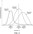
- Figure 3 is provided to emphasise that the invention is not limited to only two different regeneration processes each having its own profile for regeneration rate versus temperature. There may be three such processes or, indeed, any number of such processes. Furthermore, it is provided to emphasise that the regeneration processes to which the method of the disclosure may by applied are not limited to the specific examples provided herein. Furthermore, it may be the case that the processes which have optimum temperatures for rate of the process may not be limited to regeneration processes. The method may be employed for targeting a plurality of temperatures for a whole range of objectives that may or may not be related to regeneration of the exhaust gas treatment apparatus.
- exhaust gas and exhaust fluid may be used interchangeably.
- the exhaust gas/fluid may include some liquid, especially solid particles such as particles of soot which, while in the solid phase, may be understood to be a constituent of exhaust gas/fluid.
- the method may be applicable to an internal combustion engine having an exhaust gas treatment apparatus that requires periodic regeneration, for example to remove deposits of soot and/or to remedy a build-up of urea deposits that may be observed as suboptimal NO x conversion.
- Different regeneration processes of the exhaust gas treatment apparatus may require different minimum and optimum temperatures.
- the method may enable an engine to exceed emission regulation requirements.
Landscapes
- Engineering & Computer Science (AREA)
- Chemical & Material Sciences (AREA)
- Combustion & Propulsion (AREA)
- Mechanical Engineering (AREA)
- General Engineering & Computer Science (AREA)
- Exhaust Gas After Treatment (AREA)
Abstract
Description
- The disclosure relates to the field of exhaust gas treatment and, in particular, to controlling operation of an exhaust gas treatment apparatus.
- An exhaust gas treatment apparatus may comprise a plurality of modules, wherein each module is intended to treat one or more constituents of an exhaust gas. The modules may be arranged in series such that exhaust gas flows through each module in sequence. In order to operate as intended, some modules may require the exhaust gas to exceed a particular temperature.
- An exhaust gas treatment apparatus may comprise a diesel oxidation catalyst module, a diesel particulate filter module downstream of the diesel oxidation catalyst module and a selective catalytic reduction module, downstream of the diesel particulate filter module. One or more of these modules may not operate as intended when the exhaust gas is below a certain temperature. Moreover, increased temperature may improve operation and efficiency of the exhaust gas treatment apparatus. Moreover, periodic increases in temperature may be beneficial for facilitating reactions in the exhaust gas treatment apparatus that result in removal of deposits to thereby clean the exhaust gas treatment apparatus. For example, periodic increases in temperature may result in burning of soot deposits that may have built up since a previous increase in temperature.
- In order to increase the temperature of the exhaust gas, it is known to use the diesel oxidation catalyst module to increase the temperature of the exhaust gas passing through it in order to increase the temperature of exhaust gas arriving downstream of the diesel oxidation catalyst. This may be achieved by introducing unburnt fuel upstream of the diesel oxidation catalyst for oxidation in the diesel oxidation catalyst thereby to increase the temperature of the exhaust gas leaving the diesel oxidation catalyst module.
- Accordingly, in addition to injection of fuel for combustion, fuel may be injected into one or more of the cylinders as a post combustion event with the intention that the fuel passes out of the one or more cylinders without oxidising. This fuel may oxidise in the diesel oxidation catalyst module and thereby increase temperature of exhaust gas therein.
- There may be further reasons why it may be desirable to increase temperature of exhaust gas in the exhaust gas treatment apparatus. These reasons may include burning deposits of urea that may otherwise build on interior surfaces of the exhaust gas treatment apparatus and also increasing the temperature of exhaust gas arriving at the selective catalytic reduction module which may increase efficiency and reliability of operation.
- Against this background there is provided the engine comprising:
- a combustion unit having an exhaust conduit and one or more combustion cylinders each having a piston, a fuel injector, an intake valve and an exhaust valve leading to the exhaust conduit;
- an exhaust gas recirculation path between the exhaust conduit and upstream of the intake valve, the exhaust gas recirculation path having an exhaust gas recirculation valve to open and close the exhaust gas recirculation path;
- an exhaust gas treatment apparatus configured to receive fluid from the exhaust conduit and comprising a first module and a second module downstream of the first module;
- the method comprising a first mode for increasing a temperature of exhaust gas in the exhaust gas treatment apparatus to a first temperature, T1, and a second mode for increasing temperature of exhaust gas in the exhaust gas treatment apparatus to a second temperature, T2, wherein T1, > T2;
- the method comprising, in both the first and second modes, injecting fuel from the fuel injector into each of the one or more combustion cylinders in a main injection event to initiate a primary combustion event that drives the piston;
- the first mode having a first mode duration, the first mode comprising: closing the exhaust gas recirculation valve; and periodically injecting fuel at a first rate of injection from the fuel injector into one of the one or more combustion cylinders in a first mode subsidiary injection event after the main injection event during a period in which the fuel injected in the first mode subsidiary injection event passes into the first module without combusting in the combustion unit for raising temperature of exhaust gas in the exhaust gas treatment apparatus by combustion therein, wherein a delay is invoked after execution of the first mode before a subsequent execution of the first mode, the delay having a delay duration of at least 50 times the first mode duration;
- the second mode having a second mode duration shorter than the first mode duration, the second mode comprising: periodically injecting fuel at a second rate of injection, wherein the second rate of injection is lower than the first rate of injection, from the fuel injector into one of the one or more combustion cylinders in a second mode subsidiary injection event after the main injection event during a period in which the fuel injected in the second mode subsidiary injection event passes into the first module without combusting in the combustion unit for raising temperature of exhaust gas in the exhaust gas treatment apparatus by combustion therein;
- the method comprising invoking the first mode when targeting the first temperature, T1, and invoking the second mode when targeting the second temperature, T2.
-
-
Figure 1 shows an exhaust gas treatment apparatus of an engine that may be controlled by the method of the present disclosure; -
Figure 2 shows a graph of nominal regeneration rate against temperature for assisting in understanding the context of the present disclosure; and -
Figure 3 shows a graph of nominal regeneration rate against temperature for assisting in understanding the context of the present disclosure. - The disclosure relates to a method of controlling an engine having an exhaust gas treatment apparatus.
- For understanding the context of the method of the disclosure, there follows a description of a possible exhaust gas treatment apparatus of an engine that may be controlled by the method. As the skilled person would readily understand, the method of the disclosure is applicable to a wide range of exhaust gas treatment apparatus and is not limited to the specific example described below, which is provided simply for assisting the reader in understanding the context of the method of the disclosure.
-
Figure 1 shows a schematic representation of an exhaust gas treatment apparatus 1 of an engine that may be controlled by the method of the disclosure. The exhaust gas treatment apparatus 1 may comprise a fluid flow path through which fluid may flow sequentially through various conduits, such as afirst conduit 10, afirst end coupling 15, asecond conduit 20, asecond end coupling 25, and athird conduit 30. The first, second andthird conduits - The fluid flow path may comprise, in series, a diesel oxidation catalyst (DOC)
module 110, a diesel particulate filter (DPF)module 120, amixer module 130, a selective catalytic reduction (SCR)module 140 and/or an ammonia oxidation catalyst (AMOX) module. - In use, fluid may be supplied to the exhaust gas treatment apparatus 1 via the inlet 4. Fluid may pass into the
DOC module 110 in the first portion of thefirst conduit 10. Prior to receipt at the inlet 4, the temperature of exhaust may be sensed by a temperature sensor (not shown). - Temperature of exhaust gas within the
DOC module 110 may be derived by a temperature sensor in the vicinity of the DOC module 110 (not shown). Alternatively, it may be inferred from temperatures obtained from one or more sensors that may be upstream and/or downstream of theDOC module 110. Alternatively, it may be inferred based on other sensed data in combination with one or more calculations and or the use of one or more data libraries. In the example exhaust gas treatment apparatus ofFigure 1 , for example,temperature sensors DOC module 110. Factors that may influence the presence, number and location of temperature sensors may include other control requirements of the engine and the exhaust gas treatment apparatus that fall outside the scope of this disclosure. - The
DOC module 110 may comprise one or more catalysts, such as palladium or platinum. These materials serve as catalysts to cause oxidation of hydrocarbons ([HC]) and carbon monoxide (CO) present in the fluid flow in order to produce carbon dioxide (CO2) and water (H2O). TheDOC module 110 may also serve to convert NO to NO2 so as to achieve a NO:NO2 ratio of 1:1. The catalysts may be distributed in a manner so as to maximise the surface area of catalyst material in order to increase effectiveness of the catalyst in catalysing reactions. - Fluid may flow from the
DOC module 110 to theDPF module 120 which comprises features which are intended to restrict onward passage of carbon (C) in the form of soot. Carbon particles in the fluid may thus be trapped in the filter. TheDPF module 120 may be regenerated through regeneration techniques. These techniques may involve controlling one or more of the temperature of the fluid, the pressure of the fluid and the proportion of unburnt fuel in the fluid at this point in the apparatus. - Exhaust gas may pass from the
DPF module 120 into thefirst end coupling 15 where it flows past the emissionsfluid injector module 16. The emissionsfluid injector module 16 may be associated with or attachable to a pump electronic tank unit (PETU). The pump electronic tank unit may comprise a tank for providing a reservoir for emissions fluid to be injected by the emissionsfluid injector module 16. Such emissions fluids may include urea or ammonia. - The PETU may further comprise a controller configured to control a volume of emissions fluid to be injected from the tank by the emissions
fluid injector module 16. The controller may have as inputs, for example, temperature information and quantity of NOx information which may be derived from sensors in theSCR module 140. - Emissions fluid (e.g. urea, ammonia) may pass from the emissions
fluid injector module 16 into the mixer module (not shown) located in thesecond conduit 20. The mixer module may comprise features for ensuring that the exhaust gas originating from thefirst conduit 10 is well mixed with the emissions fluid originating from the emissionsfluid injector module 16, to create a mixed fluid. - The mixed fluid from the
second conduit 20 may pass into the SCR module located in the first portion of the third conduit via thesecond end coupling 25. TheSCR module 140 may comprise one or more catalysts through which the mixed fluid may flow. As the mixed fluid passes over the surfaces of the catalyst, a reaction may occur that converts the ammonia and NOx to diatomic nitrogen (N2) and water (H2O). - Fluid may pass from the
SCR module 140 to the AMOX module (not shown inFigure 1 ) that may be located in the second (downstream) portion of thethird conduit 30. The AMOX module may comprise an oxidation catalyst which may cause residual ammonia present in the fluid exiting the SCR module to react to produce nitrogen (N2) and water (H2O). - Fluid may pass from the AMOX module to the exhaust gas treatment apparatus outlet located at the
second end 32 of thethird conduit 30. - In addition to the exhaust gas treatment apparatus, the engine may comprise a combustion unit having an exhaust conduit and one or more combustion cylinders (not shown in
Figure 1 ). Each of the one or more cylinders may comprise a piston, a fuel injector, an intake valve and an exhaust valve leading to the exhaust conduit. Fuel may be injected into the (or each) combustion cylinder via the fuel injector. The fuel injector may be configured to inject fuel in accordance with a controlled timing pattern. - The engine may also comprise an exhaust gas recirculation path between the exhaust conduit and upstream of the intake valve. The exhaust gas recirculation path may comprise an exhaust gas recirculation valve to open and close the exhaust gas recirculation path.
- In order to increase a temperature of exhaust gas in the exhaust gas treatment apparatus, for example to facilitate a regeneration process, it is known to burn fuel in the
DOC module 110 for the purpose of increasing exhaust gas temperature. While it is possible to inject fuel for this purpose directly into theDOC module 110, it is also possible to avoid the need for a separate injector by employing the fuel injector already present in the combustion cylinder(s) of the engine. This may involve injection of fuel for combustion in theDOC module 110 by injecting it into the combustion cylinder(s) of the engine at a time in the combustion cycle (e.g. during an exhaust stroke of the cylinder) when conditions are such that the fuel will pass directly through the cylinder without burning and therefore be available for combustion within theDOC module 110. Such injections may be termed subsidiary injections so as to distinguish them from main injections that are timed so as to combust in the cylinder and so drive the piston in a conventional manner. - When injecting fuel in a subsidiary injection, it may be necessary to close the exhaust gas recirculation valve in order (a) to avoid the fuel passing directly back into the cylinder which may cause sub-optimal performance due to its effect on air to fuel ratio and (b) to avoid that fuel being unavailable for its intended purpose of combustion within the
DOC module 110. - A process intended to result in improved efficiency of the exhaust gas treatment apparatus (e.g. by removal of soot deposits from the DPF module) may be described as a regeneration process. Some regeneration processes may be NO2-based regeneration processes. Other regeneration processes may be oxygen-based regeneration processes. An optimum temperature for a NO2-based regeneration process may be different from (e.g. lower than) an optimum temperature for an oxygen-based regeneration process.
- For each chemical reaction (e.g. each regeneration process) that is to take place in the exhaust gas treatment apparatus, there may be a desired minimum temperature. Moreover, each chemical reaction may have an optimum temperature at which the process rate may be optimum. Furthermore, above the optimum temperature it may be that a benefit to the rate of the chemical reaction of further increases in temperature may be increasingly limited.
-
Figure 2 shows a graph representing regeneration rate versus temperature for NO2-based regeneration and also for oxygen-based regeneration. As shown, it may be the case that the optimum rate for NO2-based regeneration occurs at a lower temperature than the optimum rate for oxygen-based regeneration. Furthermore, it may be the case that, at temperatures below the respective optimum temperatures, the increase in rate for NO2-based regeneration is greater than that for oxygen-based regeneration. - The method of the present disclosure may involve having a first mode and a second mode for injecting subsidiary injections of fuel. In both modes, the subsidiary injections may be in addition to main injections that are timed to combust in the cylinder for effecting movement of the piston. In this way, the fuel injected at subsidiary injections may be efficiently converted directly into heat of the exhaust gas.
- The first mode may have as its objective a desire to increase temperature of exhaust gas in the exhaust gas treatment apparatus to a target temperature, T1. The second mode may have as its objective a desire to increase temperature of exhaust gas in the exhaust gas treatment apparatus to a target temperature, T2. T1 may be a temperature required in order to reach or exceed an optimum temperature of oxygen-based regeneration. T2 may be a temperature required in order to reach or exceed an optimum temperature of NO2-based regeneration. T1 may be greater than T2. For example, and with reference to
Figure 2 , an optimum temperature for oxygen-based regeneration, T1, may be 575 °C. Similarly, an optimum temperature for NO2-based regeneration, T2, may be 375 °C. - In the first mode, to achieve T1, it may be necessary to inject a relatively larger quantity of fuel in the subsidiary injections over a period of perhaps 15 minutes, perhaps 30 minutes, perhaps 45 minutes, dependent upon a variety of variables including engine load and ambient conditions.
- In order to comply with regulatory requirements, it may be necessary to have a minimum period in between the conclusion of a first period in the first mode and the commencement of a second period in the first mode. For example, the minimum period may be 80 hours, 100 hours, 120 hours or more.
- In the second mode, to achieve T2, it may be necessary to inject a relatively smaller quantity of fuel in the subsidiary injections over a shorter period, perhaps under 30 seconds or perhaps under 15 seconds.
- In the first mode, it may be necessary for the exhaust gas recirculation valve always to be closed.
- In the second mode, however, it may be possible for the exhaust gas recirculation valve to be open, at least intermittently.
- For example, the second mode subsidiary injection events may take place during successive injection timing windows of the second mode during which the exhaust gas recirculation valve is closed. In addition, the second mode may also comprise exhaust gas recirculation timing windows. In this way, the second mode may allow for alternation between injection timing windows and exhaust gas recirculation timing windows. In the second mode, therefore, exhaust gas recirculation may not be always precluded.
- In this way, the second mode may be less noticeable to a user of the internal combustion engine that the first mode. This is because, while the absence of exhaust gas recirculation in the first mode may be particularly noticeable, the intermittent absence of exhaust gas recirculation in the second mode may be less noticeable.
- It may be particularly appropriate to use the second mode when, for example, at a time when oxygen-based regeneration is not deemed to be necessary but when NO2-based regeneration is considered to be beneficial. It may also be particularly appropriate to use the second mode at a time when, for example, a minimum delay between first mode episodes has not been reached but regeneration is nevertheless considered to be beneficial.
- Use of the first mode may be particularly appropriate in circumstances where both oxygen-based regeneration and NO2-based regeneration is considered to be beneficial, or where only oxygen-based regeneration is considered to be beneficial.
- It may be the case that the second mode can be configured to coordinate with regular engine running calibration such some or all of the injection timing windows coincide with engine running calibration periods that do not in any case require exhaust gas recirculation. In this way, the second mode may be calibrated in an opportunistic fashion to take advantage of periods when the exhaust gas recirculation valve would in any case be closed and coordinate these to coincide with the injection timing windows.
-
Figure 3 is provided to emphasise that the invention is not limited to only two different regeneration processes each having its own profile for regeneration rate versus temperature. There may be three such processes or, indeed, any number of such processes. Furthermore, it is provided to emphasise that the regeneration processes to which the method of the disclosure may by applied are not limited to the specific examples provided herein. Furthermore, it may be the case that the processes which have optimum temperatures for rate of the process may not be limited to regeneration processes. The method may be employed for targeting a plurality of temperatures for a whole range of objectives that may or may not be related to regeneration of the exhaust gas treatment apparatus. - The terms exhaust gas and exhaust fluid may be used interchangeably. The exhaust gas/fluid may include some liquid, especially solid particles such as particles of soot which, while in the solid phase, may be understood to be a constituent of exhaust gas/fluid.
- The method may be applicable to an internal combustion engine having an exhaust gas treatment apparatus that requires periodic regeneration, for example to remove deposits of soot and/or to remedy a build-up of urea deposits that may be observed as suboptimal NOx conversion. Different regeneration processes of the exhaust gas treatment apparatus may require different minimum and optimum temperatures. The method may enable an engine to exceed emission regulation requirements.
Claims (15)
- A method of controlling operation of an engine, the engine comprising:a combustion unit having an exhaust conduit and one or more combustion cylinders each having a piston, a fuel injector, an intake valve and an exhaust valve leading to the exhaust conduit;an exhaust gas recirculation path between the exhaust conduit and upstream of the intake valve, the exhaust gas recirculation path having an exhaust gas recirculation valve to open and close the exhaust gas recirculation path;an exhaust gas treatment apparatus configured to receive fluid from the exhaust conduit and comprising a first module and a second module downstream of the first module;the method comprising a first mode for increasing a temperature of exhaust gas in the exhaust gas treatment apparatus to a first temperature, T1, and a second mode for increasing temperature of exhaust gas in the exhaust gas treatment apparatus to a second temperature, T2, wherein T1, > T2;the method comprising, in both the first and second modes, injecting fuel from the fuel injector into each of the one or more combustion cylinders in a main injection event to initiate a primary combustion event that drives the piston;the first mode having a first mode duration, the first mode comprising: closing the exhaust gas recirculation valve; and periodically injecting fuel at a first rate of injection from the fuel injector into one of the one or more combustion cylinders in a first mode subsidiary injection event after the main injection event during a period in which the fuel injected in the first mode subsidiary injection event passes into the first module without combusting in the combustion unit for raising temperature of exhaust gas in the exhaust gas treatment apparatus by combustion therein, wherein a delay is invoked after execution of the first mode before a subsequent execution of the first mode, the delay having a delay duration of at least 50 times the first mode duration;the second mode having a second mode duration shorter than the first mode duration, the second mode comprising: periodically injecting fuel at a second rate of injection, wherein the second rate of injection is lower than the first rate of injection, from the fuel injector into one of the one or more combustion cylinders in a second mode subsidiary injection event after the main injection event during a period in which the fuel injected in the second mode subsidiary injection event passes into the first module without combusting in the combustion unit for raising temperature of exhaust gas in the exhaust gas treatment apparatus by combustion therein;the method comprising invoking the first mode when targeting the first temperature, T1, and invoking the second mode when targeting the second temperature, T2.
- The method of claim 1 wherein the second mode comprises closing the exhaust gas recirculation valve.
- The method of claim 1 or claim 2 wherein the second mode subsidiary injection events take place during successive injection timing windows during which the exhaust gas recirculation valve is closed, and wherein the second mode comprises alternating between injection timing windows and exhaust gas recirculation timing windows in which the exhaust gas recirculation valve is open.
- The method of claim 3 wherein the engine further comprises a controller, the controller configured to receive an average desired rate of subsidiary injection and to calculate an increased rate of subsidiary injection to be injected only during the injection timing windows such that the average desired rate of subsidiary injection is maintained across a period comprising the injection timing windows and the exhaust gas recirculation timing windows.
- The method of claim 3 or claim 4 a ratio of injection timing window duration to exhaust gas recirculation timing window duration is approximately 1:4.
- The method of any preceding claim wherein the first temperature, T1 is between 550 °C and 600 °C.
- The method of any preceding claim wherein the second temperature, T2, is between 350 °C and 400 °C.
- The method of any preceding claim wherein the first mode duration ≥ 15 minutes, preferably ≥ 30 minutes, more preferably ≥ 45 minutes.
- The method of any preceding claim wherein the delay duration ≥ 80 hours, preferably ≥ 100 hours, more preferably ≥ 120 hours.
- The method of any preceding claim wherein the second mode duration ≤ 1 minute, preferably ≤ 30 seconds, more preferably ≤ 15 seconds.
- The method of any preceding claim comprising combustion of the fuel injected in the subsidiary injection event in the upstream module of the exhaust gas treatment apparatus.
- The method of any preceding claim wherein the upstream module of the exhaust gas treatment apparatus comprises a diesel oxidation catalyst.
- The method of any preceding claim further comprising providing a temperature sensor in a vicinity of the diesel oxidation catalyst configured to provide the temperature data value indicative of the temperature of gas within the diesel oxidation catalyst module.
- The method of any preceding claim wherein the delay duration is at least 60 times the first mode duration, optionally at least 70 times the first mode duration, optionally at least 80 times the first mode duration; optionally at least 90 times the first mode duration; and optionally at least 100 times the first mode duration.
- An internal combustion engine comprising:a combustion unit having an exhaust conduit and one or more combustion cylinders each having a piston, a fuel injector, an intake valve and an exhaust valve leading to the exhaust conduit;an exhaust gas recirculation path between the exhaust conduit and upstream of the intake valve, the exhaust gas recirculation path having an exhaust gas recirculation valve to open and close the exhaust gas recirculation path;an exhaust gas treatment apparatus configured to receive fluid from the exhaust conduit and comprising an upstream module and a downstream module;a controller configured to execute the method of any preceding claim.
Applications Claiming Priority (1)
| Application Number | Priority Date | Filing Date | Title |
|---|---|---|---|
| GB1610662.7A GB2551503B8 (en) | 2016-06-17 | 2016-06-17 | Method of controlling operation of an exhaust gas treatment apparatus |
Publications (2)
| Publication Number | Publication Date |
|---|---|
| EP3258093A1 true EP3258093A1 (en) | 2017-12-20 |
| EP3258093B1 EP3258093B1 (en) | 2019-04-03 |
Family
ID=56895004
Family Applications (1)
| Application Number | Title | Priority Date | Filing Date |
|---|---|---|---|
| EP17175091.2A Active EP3258093B1 (en) | 2016-06-17 | 2017-06-08 | Method of controlling operation of an exhaust gas treatment apparatus |
Country Status (2)
| Country | Link |
|---|---|
| EP (1) | EP3258093B1 (en) |
| GB (1) | GB2551503B8 (en) |
Citations (3)
| Publication number | Priority date | Publication date | Assignee | Title |
|---|---|---|---|---|
| EP1245814A2 (en) * | 2001-03-27 | 2002-10-02 | Mitsubishi Jidosha Kogyo Kabushiki Kaisha | Exhaust emission control system of internal combustion engine |
| EP1387071A1 (en) * | 2002-07-31 | 2004-02-04 | Mazda Motor Corporation | Engine exhaust gas purification apparatus |
| US20050241299A1 (en) * | 2004-04-30 | 2005-11-03 | Brown David B | Low emission diesel particulate filter (DPF) regeneration |
Family Cites Families (1)
| Publication number | Priority date | Publication date | Assignee | Title |
|---|---|---|---|---|
| JP4930215B2 (en) * | 2007-06-25 | 2012-05-16 | 株式会社デンソー | Exhaust purification device |
-
2016
- 2016-06-17 GB GB1610662.7A patent/GB2551503B8/en not_active Expired - Fee Related
-
2017
- 2017-06-08 EP EP17175091.2A patent/EP3258093B1/en active Active
Patent Citations (3)
| Publication number | Priority date | Publication date | Assignee | Title |
|---|---|---|---|---|
| EP1245814A2 (en) * | 2001-03-27 | 2002-10-02 | Mitsubishi Jidosha Kogyo Kabushiki Kaisha | Exhaust emission control system of internal combustion engine |
| EP1387071A1 (en) * | 2002-07-31 | 2004-02-04 | Mazda Motor Corporation | Engine exhaust gas purification apparatus |
| US20050241299A1 (en) * | 2004-04-30 | 2005-11-03 | Brown David B | Low emission diesel particulate filter (DPF) regeneration |
Also Published As
| Publication number | Publication date |
|---|---|
| GB2551503B8 (en) | 2019-07-17 |
| GB201610662D0 (en) | 2016-08-03 |
| GB2551503B (en) | 2019-04-24 |
| GB2551503A (en) | 2017-12-27 |
| EP3258093B1 (en) | 2019-04-03 |
Similar Documents
| Publication | Publication Date | Title |
|---|---|---|
| EP3141718B1 (en) | Asynchronous reductant insertion in aftertreatment systems | |
| EP2060756B1 (en) | Method and system using a reduction catalyst to reduce nitrate oxide | |
| CN102022170B (en) | Intrusive SCR efficiency testing system and method for vehicle with low temperature exhaust gas | |
| CN104285049B (en) | Exhaust gas purification system and exhaust gas purification method | |
| WO2013172215A1 (en) | Exhaust gas purification system and method for purifying exhaust gas | |
| CN104508266B (en) | Exhaust gas treatment device functional check | |
| CN104487684B (en) | Method of controlling operation of an engine having an exhaust fluid recirculation device and an exhaust fluid treatment device | |
| US20120144802A1 (en) | Exhaust system having doc regeneration strategy | |
| JP2016530423A (en) | Soot uptake identification system | |
| JP2013142363A (en) | Exhaust emission control device of diesel engine | |
| CN104487667B (en) | Method of controlling operation of a discharge fluid treatment device | |
| AU2016201027A1 (en) | Systems and methods for determining the quantity of a combustion product in a vehicle exhaust | |
| JP4521824B2 (en) | Exhaust purification device | |
| US11028751B2 (en) | Method of controlling operation of an exhaust gas treatment apparatus | |
| CN103032137A (en) | Exhaust gas purification apparatus of engine | |
| US10060323B1 (en) | Method and system for monitoring reductant delivery performance for an SCR catalyst | |
| EP3258093B1 (en) | Method of controlling operation of an exhaust gas treatment apparatus | |
| CN115704332A (en) | Method of controlling operation of an exhaust gas treatment device | |
| JP6629566B2 (en) | Exhaust gas purification device |
Legal Events
| Date | Code | Title | Description |
|---|---|---|---|
| PUAI | Public reference made under article 153(3) epc to a published international application that has entered the european phase |
Free format text: ORIGINAL CODE: 0009012 |
|
| STAA | Information on the status of an ep patent application or granted ep patent |
Free format text: STATUS: THE APPLICATION HAS BEEN PUBLISHED |
|
| AK | Designated contracting states |
Kind code of ref document: A1 Designated state(s): AL AT BE BG CH CY CZ DE DK EE ES FI FR GB GR HR HU IE IS IT LI LT LU LV MC MK MT NL NO PL PT RO RS SE SI SK SM TR |
|
| AX | Request for extension of the european patent |
Extension state: BA ME |
|
| STAA | Information on the status of an ep patent application or granted ep patent |
Free format text: STATUS: REQUEST FOR EXAMINATION WAS MADE |
|
| 17P | Request for examination filed |
Effective date: 20180615 |
|
| RBV | Designated contracting states (corrected) |
Designated state(s): AL AT BE BG CH CY CZ DE DK EE ES FI FR GB GR HR HU IE IS IT LI LT LU LV MC MK MT NL NO PL PT RO RS SE SI SK SM TR |
|
| GRAP | Despatch of communication of intention to grant a patent |
Free format text: ORIGINAL CODE: EPIDOSNIGR1 |
|
| STAA | Information on the status of an ep patent application or granted ep patent |
Free format text: STATUS: GRANT OF PATENT IS INTENDED |
|
| INTG | Intention to grant announced |
Effective date: 20181018 |
|
| GRAS | Grant fee paid |
Free format text: ORIGINAL CODE: EPIDOSNIGR3 |
|
| GRAA | (expected) grant |
Free format text: ORIGINAL CODE: 0009210 |
|
| STAA | Information on the status of an ep patent application or granted ep patent |
Free format text: STATUS: THE PATENT HAS BEEN GRANTED |
|
| AK | Designated contracting states |
Kind code of ref document: B1 Designated state(s): AL AT BE BG CH CY CZ DE DK EE ES FI FR GB GR HR HU IE IS IT LI LT LU LV MC MK MT NL NO PL PT RO RS SE SI SK SM TR |
|
| REG | Reference to a national code |
Ref country code: GB Ref legal event code: FG4D |
|
| REG | Reference to a national code |
Ref country code: CH Ref legal event code: EP Ref country code: AT Ref legal event code: REF Ref document number: 1116044 Country of ref document: AT Kind code of ref document: T Effective date: 20190415 |
|
| REG | Reference to a national code |
Ref country code: DE Ref legal event code: R096 Ref document number: 602017003031 Country of ref document: DE |
|
| REG | Reference to a national code |
Ref country code: IE Ref legal event code: FG4D |
|
| REG | Reference to a national code |
Ref country code: NL Ref legal event code: MP Effective date: 20190403 |
|
| REG | Reference to a national code |
Ref country code: LT Ref legal event code: MG4D |
|
| REG | Reference to a national code |
Ref country code: AT Ref legal event code: MK05 Ref document number: 1116044 Country of ref document: AT Kind code of ref document: T Effective date: 20190403 |
|
| PG25 | Lapsed in a contracting state [announced via postgrant information from national office to epo] |
Ref country code: NL Free format text: LAPSE BECAUSE OF FAILURE TO SUBMIT A TRANSLATION OF THE DESCRIPTION OR TO PAY THE FEE WITHIN THE PRESCRIBED TIME-LIMIT Effective date: 20190403 |
|
| PG25 | Lapsed in a contracting state [announced via postgrant information from national office to epo] |
Ref country code: HR Free format text: LAPSE BECAUSE OF FAILURE TO SUBMIT A TRANSLATION OF THE DESCRIPTION OR TO PAY THE FEE WITHIN THE PRESCRIBED TIME-LIMIT Effective date: 20190403 Ref country code: LT Free format text: LAPSE BECAUSE OF FAILURE TO SUBMIT A TRANSLATION OF THE DESCRIPTION OR TO PAY THE FEE WITHIN THE PRESCRIBED TIME-LIMIT Effective date: 20190403 Ref country code: NO Free format text: LAPSE BECAUSE OF FAILURE TO SUBMIT A TRANSLATION OF THE DESCRIPTION OR TO PAY THE FEE WITHIN THE PRESCRIBED TIME-LIMIT Effective date: 20190703 Ref country code: FI Free format text: LAPSE BECAUSE OF FAILURE TO SUBMIT A TRANSLATION OF THE DESCRIPTION OR TO PAY THE FEE WITHIN THE PRESCRIBED TIME-LIMIT Effective date: 20190403 Ref country code: PT Free format text: LAPSE BECAUSE OF FAILURE TO SUBMIT A TRANSLATION OF THE DESCRIPTION OR TO PAY THE FEE WITHIN THE PRESCRIBED TIME-LIMIT Effective date: 20190803 Ref country code: AL Free format text: LAPSE BECAUSE OF FAILURE TO SUBMIT A TRANSLATION OF THE DESCRIPTION OR TO PAY THE FEE WITHIN THE PRESCRIBED TIME-LIMIT Effective date: 20190403 Ref country code: SE Free format text: LAPSE BECAUSE OF FAILURE TO SUBMIT A TRANSLATION OF THE DESCRIPTION OR TO PAY THE FEE WITHIN THE PRESCRIBED TIME-LIMIT Effective date: 20190403 Ref country code: CZ Free format text: LAPSE BECAUSE OF FAILURE TO SUBMIT A TRANSLATION OF THE DESCRIPTION OR TO PAY THE FEE WITHIN THE PRESCRIBED TIME-LIMIT Effective date: 20190403 Ref country code: ES Free format text: LAPSE BECAUSE OF FAILURE TO SUBMIT A TRANSLATION OF THE DESCRIPTION OR TO PAY THE FEE WITHIN THE PRESCRIBED TIME-LIMIT Effective date: 20190403 |
|
| PG25 | Lapsed in a contracting state [announced via postgrant information from national office to epo] |
Ref country code: BG Free format text: LAPSE BECAUSE OF FAILURE TO SUBMIT A TRANSLATION OF THE DESCRIPTION OR TO PAY THE FEE WITHIN THE PRESCRIBED TIME-LIMIT Effective date: 20190703 Ref country code: GR Free format text: LAPSE BECAUSE OF FAILURE TO SUBMIT A TRANSLATION OF THE DESCRIPTION OR TO PAY THE FEE WITHIN THE PRESCRIBED TIME-LIMIT Effective date: 20190704 Ref country code: RS Free format text: LAPSE BECAUSE OF FAILURE TO SUBMIT A TRANSLATION OF THE DESCRIPTION OR TO PAY THE FEE WITHIN THE PRESCRIBED TIME-LIMIT Effective date: 20190403 Ref country code: LV Free format text: LAPSE BECAUSE OF FAILURE TO SUBMIT A TRANSLATION OF THE DESCRIPTION OR TO PAY THE FEE WITHIN THE PRESCRIBED TIME-LIMIT Effective date: 20190403 Ref country code: PL Free format text: LAPSE BECAUSE OF FAILURE TO SUBMIT A TRANSLATION OF THE DESCRIPTION OR TO PAY THE FEE WITHIN THE PRESCRIBED TIME-LIMIT Effective date: 20190403 |
|
| PG25 | Lapsed in a contracting state [announced via postgrant information from national office to epo] |
Ref country code: IS Free format text: LAPSE BECAUSE OF FAILURE TO SUBMIT A TRANSLATION OF THE DESCRIPTION OR TO PAY THE FEE WITHIN THE PRESCRIBED TIME-LIMIT Effective date: 20190803 Ref country code: AT Free format text: LAPSE BECAUSE OF FAILURE TO SUBMIT A TRANSLATION OF THE DESCRIPTION OR TO PAY THE FEE WITHIN THE PRESCRIBED TIME-LIMIT Effective date: 20190403 |
|
| REG | Reference to a national code |
Ref country code: DE Ref legal event code: R097 Ref document number: 602017003031 Country of ref document: DE |
|
| PG25 | Lapsed in a contracting state [announced via postgrant information from national office to epo] |
Ref country code: EE Free format text: LAPSE BECAUSE OF FAILURE TO SUBMIT A TRANSLATION OF THE DESCRIPTION OR TO PAY THE FEE WITHIN THE PRESCRIBED TIME-LIMIT Effective date: 20190403 Ref country code: SK Free format text: LAPSE BECAUSE OF FAILURE TO SUBMIT A TRANSLATION OF THE DESCRIPTION OR TO PAY THE FEE WITHIN THE PRESCRIBED TIME-LIMIT Effective date: 20190403 Ref country code: MC Free format text: LAPSE BECAUSE OF FAILURE TO SUBMIT A TRANSLATION OF THE DESCRIPTION OR TO PAY THE FEE WITHIN THE PRESCRIBED TIME-LIMIT Effective date: 20190403 Ref country code: DK Free format text: LAPSE BECAUSE OF FAILURE TO SUBMIT A TRANSLATION OF THE DESCRIPTION OR TO PAY THE FEE WITHIN THE PRESCRIBED TIME-LIMIT Effective date: 20190403 Ref country code: RO Free format text: LAPSE BECAUSE OF FAILURE TO SUBMIT A TRANSLATION OF THE DESCRIPTION OR TO PAY THE FEE WITHIN THE PRESCRIBED TIME-LIMIT Effective date: 20190403 |
|
| PLBE | No opposition filed within time limit |
Free format text: ORIGINAL CODE: 0009261 |
|
| STAA | Information on the status of an ep patent application or granted ep patent |
Free format text: STATUS: NO OPPOSITION FILED WITHIN TIME LIMIT |
|
| PG25 | Lapsed in a contracting state [announced via postgrant information from national office to epo] |
Ref country code: SM Free format text: LAPSE BECAUSE OF FAILURE TO SUBMIT A TRANSLATION OF THE DESCRIPTION OR TO PAY THE FEE WITHIN THE PRESCRIBED TIME-LIMIT Effective date: 20190403 Ref country code: IT Free format text: LAPSE BECAUSE OF FAILURE TO SUBMIT A TRANSLATION OF THE DESCRIPTION OR TO PAY THE FEE WITHIN THE PRESCRIBED TIME-LIMIT Effective date: 20190403 |
|
| 26N | No opposition filed |
Effective date: 20200106 |
|
| REG | Reference to a national code |
Ref country code: BE Ref legal event code: MM Effective date: 20190630 |
|
| PG25 | Lapsed in a contracting state [announced via postgrant information from national office to epo] |
Ref country code: TR Free format text: LAPSE BECAUSE OF FAILURE TO SUBMIT A TRANSLATION OF THE DESCRIPTION OR TO PAY THE FEE WITHIN THE PRESCRIBED TIME-LIMIT Effective date: 20190403 |
|
| PG25 | Lapsed in a contracting state [announced via postgrant information from national office to epo] |
Ref country code: IE Free format text: LAPSE BECAUSE OF NON-PAYMENT OF DUE FEES Effective date: 20190608 |
|
| PG25 | Lapsed in a contracting state [announced via postgrant information from national office to epo] |
Ref country code: SI Free format text: LAPSE BECAUSE OF FAILURE TO SUBMIT A TRANSLATION OF THE DESCRIPTION OR TO PAY THE FEE WITHIN THE PRESCRIBED TIME-LIMIT Effective date: 20190403 Ref country code: LU Free format text: LAPSE BECAUSE OF NON-PAYMENT OF DUE FEES Effective date: 20190608 Ref country code: BE Free format text: LAPSE BECAUSE OF NON-PAYMENT OF DUE FEES Effective date: 20190630 |
|
| PG25 | Lapsed in a contracting state [announced via postgrant information from national office to epo] |
Ref country code: FR Free format text: LAPSE BECAUSE OF NON-PAYMENT OF DUE FEES Effective date: 20190630 |
|
| REG | Reference to a national code |
Ref country code: CH Ref legal event code: PL |
|
| PG25 | Lapsed in a contracting state [announced via postgrant information from national office to epo] |
Ref country code: LI Free format text: LAPSE BECAUSE OF NON-PAYMENT OF DUE FEES Effective date: 20200630 Ref country code: CH Free format text: LAPSE BECAUSE OF NON-PAYMENT OF DUE FEES Effective date: 20200630 |
|
| PG25 | Lapsed in a contracting state [announced via postgrant information from national office to epo] |
Ref country code: CY Free format text: LAPSE BECAUSE OF FAILURE TO SUBMIT A TRANSLATION OF THE DESCRIPTION OR TO PAY THE FEE WITHIN THE PRESCRIBED TIME-LIMIT Effective date: 20190403 |
|
| PG25 | Lapsed in a contracting state [announced via postgrant information from national office to epo] |
Ref country code: MT Free format text: LAPSE BECAUSE OF FAILURE TO SUBMIT A TRANSLATION OF THE DESCRIPTION OR TO PAY THE FEE WITHIN THE PRESCRIBED TIME-LIMIT Effective date: 20190403 Ref country code: HU Free format text: LAPSE BECAUSE OF FAILURE TO SUBMIT A TRANSLATION OF THE DESCRIPTION OR TO PAY THE FEE WITHIN THE PRESCRIBED TIME-LIMIT; INVALID AB INITIO Effective date: 20170608 |
|
| PG25 | Lapsed in a contracting state [announced via postgrant information from national office to epo] |
Ref country code: MK Free format text: LAPSE BECAUSE OF FAILURE TO SUBMIT A TRANSLATION OF THE DESCRIPTION OR TO PAY THE FEE WITHIN THE PRESCRIBED TIME-LIMIT Effective date: 20190403 |
|
| P01 | Opt-out of the competence of the unified patent court (upc) registered |
Effective date: 20230517 |
|
| PGFP | Annual fee paid to national office [announced via postgrant information from national office to epo] |
Ref country code: DE Payment date: 20250520 Year of fee payment: 9 |
|
| PGFP | Annual fee paid to national office [announced via postgrant information from national office to epo] |
Ref country code: GB Payment date: 20250520 Year of fee payment: 9 |