EP3258074A1 - Steam power plant for generating electrical energy - Google Patents
Steam power plant for generating electrical energy Download PDFInfo
- Publication number
- EP3258074A1 EP3258074A1 EP16174432.1A EP16174432A EP3258074A1 EP 3258074 A1 EP3258074 A1 EP 3258074A1 EP 16174432 A EP16174432 A EP 16174432A EP 3258074 A1 EP3258074 A1 EP 3258074A1
- Authority
- EP
- European Patent Office
- Prior art keywords
- steam
- pipeline
- power plant
- bypass
- turbine section
- Prior art date
- Legal status (The legal status is an assumption and is not a legal conclusion. Google has not performed a legal analysis and makes no representation as to the accuracy of the status listed.)
- Withdrawn
Links
Images


Classifications
-
- F—MECHANICAL ENGINEERING; LIGHTING; HEATING; WEAPONS; BLASTING
- F01—MACHINES OR ENGINES IN GENERAL; ENGINE PLANTS IN GENERAL; STEAM ENGINES
- F01K—STEAM ENGINE PLANTS; STEAM ACCUMULATORS; ENGINE PLANTS NOT OTHERWISE PROVIDED FOR; ENGINES USING SPECIAL WORKING FLUIDS OR CYCLES
- F01K7/00—Steam engine plants characterised by the use of specific types of engine; Plants or engines characterised by their use of special steam systems, cycles or processes; Control means specially adapted for such systems, cycles or processes; Use of withdrawn or exhaust steam for feed-water heating
- F01K7/16—Steam engine plants characterised by the use of specific types of engine; Plants or engines characterised by their use of special steam systems, cycles or processes; Control means specially adapted for such systems, cycles or processes; Use of withdrawn or exhaust steam for feed-water heating the engines being only of turbine type
- F01K7/165—Controlling means specially adapted therefor
-
- F—MECHANICAL ENGINEERING; LIGHTING; HEATING; WEAPONS; BLASTING
- F01—MACHINES OR ENGINES IN GENERAL; ENGINE PLANTS IN GENERAL; STEAM ENGINES
- F01K—STEAM ENGINE PLANTS; STEAM ACCUMULATORS; ENGINE PLANTS NOT OTHERWISE PROVIDED FOR; ENGINES USING SPECIAL WORKING FLUIDS OR CYCLES
- F01K13/00—General layout or general methods of operation of complete plants
- F01K13/02—Controlling, e.g. stopping or starting
-
- F—MECHANICAL ENGINEERING; LIGHTING; HEATING; WEAPONS; BLASTING
- F01—MACHINES OR ENGINES IN GENERAL; ENGINE PLANTS IN GENERAL; STEAM ENGINES
- F01K—STEAM ENGINE PLANTS; STEAM ACCUMULATORS; ENGINE PLANTS NOT OTHERWISE PROVIDED FOR; ENGINES USING SPECIAL WORKING FLUIDS OR CYCLES
- F01K7/00—Steam engine plants characterised by the use of specific types of engine; Plants or engines characterised by their use of special steam systems, cycles or processes; Control means specially adapted for such systems, cycles or processes; Use of withdrawn or exhaust steam for feed-water heating
- F01K7/02—Steam engine plants characterised by the use of specific types of engine; Plants or engines characterised by their use of special steam systems, cycles or processes; Control means specially adapted for such systems, cycles or processes; Use of withdrawn or exhaust steam for feed-water heating the engines being of multiple-expansion type
- F01K7/025—Consecutive expansion in a turbine or a positive displacement engine
Definitions
- the present invention relates to the field of power generation systems, and more particularly relates to a steam power plant for generating electrical energy.
- heat energy is converted into mechanical energy and ultimately into electrical energy, wherein steam from the steam generator flows into an expansion machine, such as steam turbine, wherein the steam is expanded in the steam turbine with output of work.
- the steam which flows from the steam turbine is liquefied again in a downstream condenser as a result of heat rejection.
- the condensed water from the condenser is circulated again to the steam generator by a feedwater pump, as a result of which a closed circuit is created.
- the steam which flows from the steam generator flows into the steam turbine and cools down in the process, wherein the steam pressure reduces.
- the steam exhaust from the steam turbine is routed through to the condenser.
- EP 2326800 A2 discloses a steam power plant for generating electrical energy.
- the steam turbine consists of a plurality of turbine sections, viz high-pressure turbine section, an intermediate-pressure turbine section, and a low-pressure turbine section.
- a main steam pipeline carrying a live steam, connects the steam generator with inlet of the high-pressure turbine section and an exhaust steam pipeline, carrying a steam exiting the high-pressure turbine section, connects the outlet of the high-pressure turbine section with a reheating unit.
- the exhaust steam pipeline that leads to the reheating unit is termed as 'cold reheat pipeline'.
- a steam pipeline which carries the reheated steam, connects the reheating unit and the inlet of the intermediate-pressure turbine section.
- This steam pipeline is known as 'hot reheat pipeline'.
- the exhaust steam exiting the intermediate-pressure turbine section is supplied to inlet of the low-pressure turbine section through an exhaust steam pipeline.
- the exhaust steam exiting the low-pressure turbine section is fed to the condenser.
- the main steam pipeline with the cold reheat pipeline is fluidically interconnected via the high-pressure bypass station.
- the hot reheat pipeline is fluidically interconnected to the condenser via an intermediate-pressure bypass station.
- the main steam valve arranged upstream of the high-pressure turbine section is closed and the main steam is directed via the high-pressure bypass station, which leads to the cold reheat pipeline.
- a cooling unit is provided in the bypass pipeline, wherein the steam is sprayed with a cooling medium (e.g., feedwater) before entry of the steam into the cold reheat pipeline to meet cold reheat steam conditions.
- a boiler feed water pump of higher capacity needs to be employed to provide the cooling medium to the cooling unit. This may add up to the cost of the steam power plant.
- a steam power plant comprising a steam turbine having a plurality of turbine sections, a steam generator, and a reheating unit.
- the plurality of turbine sections comprises a high-pressure turbine section, an intermediate-pressure turbine section, and a low pressure turbine section.
- the steam power plant also comprises a main steam pipeline which fluidically interconnects a steam inlet of the first turbine section with the steam generator.
- the first turbine section is the high-pressure turbine section.
- the steam power plant comprises a hot reheat pipeline which fluidically interconnects the reheating unit with a steam inlet of the second turbine section.
- the second turbine section is the intermediate-pressure turbine section.
- the steam power plant comprises a first bypass station which fluidically interconnects the main steam pipeline with the hot reheat pipeline.
- the first bypass station comprises a bypass pipeline and a bypass pressure reducing means such as a pressure valve arranged in the bypass pipeline.
- the first bypass station does not employ a cooling unit.
- the steam power plant comprises a cold reheat pipeline which fluidically interconnects a steam outlet of the first turbine section with the reheating unit.
- the steam generator is fluidically connected to the cold reheat pipeline.
- the steam generator is connected to the cold reheat pipeline prior to the reheating unit.
- the steam power plant also comprises a pressure reducing means provided between the steam generator and the cold reheat pipeline.
- the steam power plant comprises a second bypass station which fluidically interconnects the hot reheat pipeline with a condenser.
- the second bypass station is an intermediate-pressure bypass station.
- the steam power plant comprises a pre-heating means connected between the main steam pipeline and the hot reheat pipeline.
- the pre-heating means is a warm-up pipeline for warming up the hot reheat pipeline during start-up condition.
- a bypass station comprising a bypass pipeline, and a bypass pressure reducing means arranged in the bypass pipeline, wherein the bypass pipeline is fluidically interconnectable to a main steam pipeline and a hot reheat pipeline of a steam power plant.
- FIG 1 illustrates a schematic diagram of a steam power plant 100 according to the prior art.
- the steam power plant 100 comprises a steam generator 102, a steam turbine 104, a reheating unit 106 and a condenser 108.
- the steam turbine 100 consists of a high-pressure turbine section 104a, an intermediate-pressure turbine section 104b, and a low-pressure turbine section 104c.
- the steam power plant 100 also comprises a main steam pipeline 110 which fluidically interconnects the steam generator 102 with the steam inlet 114 of the high-pressure turbine section 104a.
- the steam power plant 100 comprises a cold reheat pipeline 112 with fluidically interconnects a steam outlet 116 of the high-pressure turbine section 104a with the reheating unit 106.
- a hot reheat pipeline 118 which fluidically interconnects the reheating unit 106 with a steam inlet 120 of the intermediate-pressure turbine section 104b.
- a steam pipeline 122 which fluidically interconnects a steam outlet 124 of the intermediate-pressure turbine section 104b with a steam inlet 126 of the low-pressure turbine section 104c is arranged downstream of the intermediate-pressure turbine section 104b.
- An exhaust steam pipeline 128 which fluidically interconnects a steam outlet 130 of the low-pressure turbine section 104c with a condenser 108 is also arranged in the steam power plant 100.
- the main steam pipeline 110 is fluidically connected via a high-pressure bypass station 132 to the cold reheat pipeline 112.
- the high-pressure bypass station 132 comprises a bypass pressure reducing valve 136, a bypass pipeline 138, and a cooling unit 142.
- the hot reheat pipeline 118 is fluidically interconnected with the condenser 108 via an intermediate-pressure bypass station 134.
- the intermediate-pressure bypass station 134 comprises a bypass valve 144, a bypass pipeline 146 and a cooling unit 148.
- the main steam pipeline 110 carries main steam from the steam generator 102 to the high-pressure turbine section 104a.
- the cold reheat pipeline 112 carries exhaust steam exiting the high-pressure turbine section 104a which flows into the reheating unit 106 where the steam is heated to high temperature, via the hot reheat pipeline 118, is directed to the intermediate-pressure turbine section 104b.
- the exhaust steam exiting the intermediate-pressure turbine section 104b is fed to the low-pressure turbine section 104c.
- the exhaust steam exiting the low-pressure turbine section 104c is fed to the condenser 108.
- the emergency shut-off and control valve 140 is closed and the bypass pressure reducing valve 136 is opened.
- the steam from the main steam pipeline 110 is directed via the high-pressure bypass station 132 into the cold reheat pipeline 112. Since the temperature of the steam which flows into the high-pressure bypass pipeline 138 is comparatively high, the steam is sprayed with a cooling medium in the cooling unit 142 before entry into the cold reheat pipeline 112. The steam is then directed via the reheating unit 106 and the hot reheat pipeline 118 to the intermediate-pressure bypass station 134, into the condenser 108.
- the steam Prior to entry to the condenser 108, the steam is sprayed with a cooling medium in a cooling unit 148 so that the condenser 108 can absorb the amount of energy.
- the cooling unit 142 is used in the high-pressure bypass station 132 to reduce the temperature of the steam. This may increase the cost of the steam power plant 100.
- FIG 2 a steam power plant 200 according to one embodiment of the present invention is shown.
- the difference to the steam power plant 100 shown in FIG 1 is that a high-pressure bypass station 202 fluidically interconnects the main steam pipeline 110 with the hot reheat pipeline 118.
- the high-pressure bypass station 202 comprises a bypass pressure reducing valve 204, and a bypass pipeline 206.
- the bypass pressure reducing valve 204 is opened and the emergency shut-off and control valve 140 is closed.
- main steam from the main steam pipeline 110 is directed via the bypass pipeline 206 to the hot reheat pipeline 118.
- the bypass pressure reducing valve 204 arranged in the bypass pipeline 206 also reduces pressure of the main steam to meet the hot reheat steam conditions.
- the steam flowing in the hot reheat pipeline 118 is directed via the intermediate-pressure bypass station 134 to the condenser 108.
- the high-pressure bypass station 202 does not employ a cooling unit for reducing the temperature of the steam unlike the steam power plant 100 of FIG 1 . Due to this, cost of the high-pressure bypass station 202 is significantly reduced. Consequently, the cost of the steam power plant 200 is lowered.
- FIG 3 a steam power plant 300 according to another embodiment of the present invention is shown.
- the steam generator 102 is fluidically interconnected to the cold reheat pipeline 112 via a pressure reducing valve 302.
- the steam generator 102 is connected to the cold reheat pipeline 112 prior to the connection with the reheating unit 106.
- saturated steam from the steam generator 102 is directed to the cold reheat pipeline 112 via the pressure reducing valve 302 wherein the pressure of the saturated steam is reduced to meet the cold heat steam conditions.
- the temperature of the saturated steam is equivalent to the cold reheat steam conditions and hence there is no need to reduce the temperature of the saturated steam.
- the steam flowing in the cold reheat pipeline 112 is fed to the reheating unit 106 where the steam is heated to high temperature.
- the reheated steam is directed via the hot reheat pipeline 118 and the intermediate-pressure bypass station 134 to the condenser 108.
- the reheated steam is mixed with the main steam from the high-pressure bypass station 202.
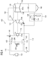
- FIG 4 a steam power plant 400 according to yet another embodiment of the present invention is shown.
- the steam power plant 400 of FIG 4 is similar to the steam power plant 300 of FIG 3 except that the steam power plant 400 comprises a pre-heating means 402 connected between the main steam pipeline 110 and the hot reheat pipeline 118.
- the pre-heating means 402 may be a warm-up pipeline provided for warming up the hot reheat pipeline 118 during warm-up operation.
- the present invention provides a steam power plant with a high pressure bypass station which does not require a cooling unit as the main steam pipeline is fludically connected to the hot reheat pipeline via the high pressure bypass station. As a result, cost of the steam power plant is reduced.
Landscapes
- Engineering & Computer Science (AREA)
- Chemical & Material Sciences (AREA)
- Combustion & Propulsion (AREA)
- Mechanical Engineering (AREA)
- General Engineering & Computer Science (AREA)
- Control Of Turbines (AREA)
- Engine Equipment That Uses Special Cycles (AREA)
Abstract
The present invention provides a steam power plant (200, 300, 400) for generating electrical energy. The steam power plant (200, 300, 400) comprises a steam turbine (104) having a plurality of turbine sections (104a, 104b, 104c), a steam generator (102), and a reheating unit (106). Also, the steam power plant (200, 300, 400) comprises a main steam pipeline (110) which fluidically interconnects a steam inlet (114) of the first turbine section (104a) with the steam generator (102), and a hot reheat pipeline (118) which fluidically interconnects the reheating unit (106) with the a steam inlet (120) of a second turbine section (104b). Moreover, the steam power plant (200, 300, 400) comprises a first bypass station (132) which fluidically interconnects the main steam pipeline (110) with the hot reheat pipeline (118). Additionally, the steam power plant (200, 300, 400) comprises a second bypass station (134) which fluidically interconnects the hot reheat pipeline (118) with a condenser (108).
Description
- The present invention relates to the field of power generation systems, and more particularly relates to a steam power plant for generating electrical energy.
- In a steam power plant, heat energy is converted into mechanical energy and ultimately into electrical energy, wherein steam from the steam generator flows into an expansion machine, such as steam turbine, wherein the steam is expanded in the steam turbine with output of work. The steam which flows from the steam turbine is liquefied again in a downstream condenser as a result of heat rejection. The condensed water from the condenser is circulated again to the steam generator by a feedwater pump, as a result of which a closed circuit is created.
- In the operating state, the steam which flows from the steam generator flows into the steam turbine and cools down in the process, wherein the steam pressure reduces. The steam exhaust from the steam turbine is routed through to the condenser.
-
EP 2326800 A2 discloses a steam power plant for generating electrical energy. The steam turbine consists of a plurality of turbine sections, viz high-pressure turbine section, an intermediate-pressure turbine section, and a low-pressure turbine section. For example, a main steam pipeline, carrying a live steam, connects the steam generator with inlet of the high-pressure turbine section and an exhaust steam pipeline, carrying a steam exiting the high-pressure turbine section, connects the outlet of the high-pressure turbine section with a reheating unit. The exhaust steam pipeline that leads to the reheating unit is termed as 'cold reheat pipeline'. A steam pipeline, which carries the reheated steam, connects the reheating unit and the inlet of the intermediate-pressure turbine section. This steam pipeline is known as 'hot reheat pipeline'. The exhaust steam exiting the intermediate-pressure turbine section is supplied to inlet of the low-pressure turbine section through an exhaust steam pipeline. The exhaust steam exiting the low-pressure turbine section is fed to the condenser. Additionally, the main steam pipeline with the cold reheat pipeline is fluidically interconnected via the high-pressure bypass station. Also, the hot reheat pipeline is fluidically interconnected to the condenser via an intermediate-pressure bypass station. - Normally, during starting, shutting down, abnormal operation, or in case of an emergency shutdown of the steam turbine, the main steam valve arranged upstream of the high-pressure turbine section is closed and the main steam is directed via the high-pressure bypass station, which leads to the cold reheat pipeline. Since the temperature and pressure of the main steam which flows in the bypass pipeline of the high-pressure bypass station is comparatively higher, a cooling unit is provided in the bypass pipeline, wherein the steam is sprayed with a cooling medium (e.g., feedwater) before entry of the steam into the cold reheat pipeline to meet cold reheat steam conditions. Additionally, a boiler feed water pump of higher capacity needs to be employed to provide the cooling medium to the cooling unit. This may add up to the cost of the steam power plant.
- In light of the above, there exists a need to provide a steam power plant which does not employ a cooling unit for cooling main steam flowing through a high-pressure bypass station.
- Therefore, it is the object of the present invention to provide a steam power plant with a bypass station which fluidically interconnects a main steam pipeline with a hot reheat pipeline, thereby eliminating need to reduce temperature of main steam flowing through the bypass station.
- The object of the present invention is achieved by a steam power plant comprising a steam turbine having a plurality of turbine sections, a steam generator, and a reheating unit. For example, the plurality of turbine sections comprises a high-pressure turbine section, an intermediate-pressure turbine section, and a low pressure turbine section.
- The steam power plant also comprises a main steam pipeline which fluidically interconnects a steam inlet of the first turbine section with the steam generator. The first turbine section is the high-pressure turbine section. Furthermore, the steam power plant comprises a hot reheat pipeline which fluidically interconnects the reheating unit with a steam inlet of the second turbine section. The second turbine section is the intermediate-pressure turbine section.
- Moreover, the steam power plant comprises a first bypass station which fluidically interconnects the main steam pipeline with the hot reheat pipeline. The first bypass station comprises a bypass pipeline and a bypass pressure reducing means such as a pressure valve arranged in the bypass pipeline. Advantageously, the first bypass station does not employ a cooling unit.
- Additionally, the steam power plant comprises a cold reheat pipeline which fluidically interconnects a steam outlet of the first turbine section with the reheating unit. Therein, the steam generator is fluidically connected to the cold reheat pipeline. Therein, the steam generator is connected to the cold reheat pipeline prior to the reheating unit. The steam power plant also comprises a pressure reducing means provided between the steam generator and the cold reheat pipeline.
- Furthermore, the steam power plant comprises a second bypass station which fluidically interconnects the hot reheat pipeline with a condenser. The second bypass station is an intermediate-pressure bypass station.
- Moreover, the steam power plant comprises a pre-heating means connected between the main steam pipeline and the hot reheat pipeline. The pre-heating means is a warm-up pipeline for warming up the hot reheat pipeline during start-up condition.
- The object of the present invention is also achieved by a bypass station comprising a bypass pipeline, and a bypass pressure reducing means arranged in the bypass pipeline, wherein the bypass pipeline is fluidically interconnectable to a main steam pipeline and a hot reheat pipeline of a steam power plant.
- The above-mentioned and other features of the invention will now be addressed with reference to the accompanying drawings of the present invention. The illustrated embodiments are intended to illustrate, but not limit the invention.
- The present invention is further described hereinafter with reference to illustrated embodiments shown in the accompanying drawings, in which:
- FIG 1
- illustrates a schematic diagram of a steam power plant according to prior art;
- FIG 2
- is a schematic diagram of a steam power plant according to one embodiment of the present invention;
- FIG 3
- is a schematic diagram of a steam power plant according to another embodiment of the present invention; and
- FIG 4
- is a schematic diagram of a steam power plant according to yet another embodiment of the present invention.
- Various embodiments are described with reference to the drawings, wherein like reference numerals are used to refer the drawings, wherein like reference numerals are used to refer to like elements throughout. In the following description, for the purpose of explanation, numerous specific details are set forth in order to provide thorough understanding of one or more embodiments. It may be evident that such embodiments may be practiced without these specific details.
-
FIG 1 illustrates a schematic diagram of asteam power plant 100 according to the prior art. Thesteam power plant 100 comprises asteam generator 102, asteam turbine 104, areheating unit 106 and acondenser 108. Thesteam turbine 100 consists of a high-pressure turbine section 104a, an intermediate-pressure turbine section 104b, and a low-pressure turbine section 104c. Thesteam power plant 100 also comprises amain steam pipeline 110 which fluidically interconnects thesteam generator 102 with thesteam inlet 114 of the high-pressure turbine section 104a. - Furthermore, the
steam power plant 100 comprises acold reheat pipeline 112 with fluidically interconnects asteam outlet 116 of the high-pressure turbine section 104a with thereheating unit 106. Ahot reheat pipeline 118 which fluidically interconnects thereheating unit 106 with asteam inlet 120 of the intermediate-pressure turbine section 104b. - A
steam pipeline 122 which fluidically interconnects asteam outlet 124 of the intermediate-pressure turbine section 104b with asteam inlet 126 of the low-pressure turbine section 104c is arranged downstream of the intermediate-pressure turbine section 104b. Anexhaust steam pipeline 128 which fluidically interconnects asteam outlet 130 of the low-pressure turbine section 104c with acondenser 108 is also arranged in thesteam power plant 100. - The
main steam pipeline 110 is fluidically connected via a high-pressure bypass station 132 to thecold reheat pipeline 112. The high-pressure bypass station 132 comprises a bypasspressure reducing valve 136, abypass pipeline 138, and acooling unit 142. Thehot reheat pipeline 118 is fluidically interconnected with thecondenser 108 via an intermediate-pressure bypass station 134. The intermediate-pressure bypass station 134 comprises abypass valve 144, abypass pipeline 146 and acooling unit 148. - During normal operation of the
steam power plant 100, themain steam pipeline 110 carries main steam from thesteam generator 102 to the high-pressure turbine section 104a. Thecold reheat pipeline 112 carries exhaust steam exiting the high-pressure turbine section 104a which flows into thereheating unit 106 where the steam is heated to high temperature, via thehot reheat pipeline 118, is directed to the intermediate-pressure turbine section 104b. The exhaust steam exiting the intermediate-pressure turbine section 104b is fed to the low-pressure turbine section 104c. The exhaust steam exiting the low-pressure turbine section 104c is fed to thecondenser 108. - During starting, shutting down, abnormal operation, or in case of emergency shut-down of the
steam turbine 104, the emergency shut-off andcontrol valve 140 is closed and the bypasspressure reducing valve 136 is opened. As a result, the steam from themain steam pipeline 110 is directed via the high-pressure bypass station 132 into thecold reheat pipeline 112. Since the temperature of the steam which flows into the high-pressure bypass pipeline 138 is comparatively high, the steam is sprayed with a cooling medium in thecooling unit 142 before entry into thecold reheat pipeline 112. The steam is then directed via thereheating unit 106 and thehot reheat pipeline 118 to the intermediate-pressure bypass station 134, into thecondenser 108. Prior to entry to thecondenser 108, the steam is sprayed with a cooling medium in acooling unit 148 so that thecondenser 108 can absorb the amount of energy. It can be noted that, thecooling unit 142 is used in the high-pressure bypass station 132 to reduce the temperature of the steam. This may increase the cost of thesteam power plant 100. - In
FIG 2 , asteam power plant 200 according to one embodiment of the present invention is shown. The difference to thesteam power plant 100 shown inFIG 1 is that a high-pressure bypass station 202 fluidically interconnects themain steam pipeline 110 with thehot reheat pipeline 118. The high-pressure bypass station 202 comprises a bypasspressure reducing valve 204, and abypass pipeline 206. During the starting, shutting down, abnormal operation, or in case of emergency shut-down of thesteam turbine 104, the bypasspressure reducing valve 204 is opened and the emergency shut-off andcontrol valve 140 is closed. As a result, main steam from themain steam pipeline 110 is directed via thebypass pipeline 206 to thehot reheat pipeline 118. The bypasspressure reducing valve 204 arranged in thebypass pipeline 206 also reduces pressure of the main steam to meet the hot reheat steam conditions. The steam flowing in thehot reheat pipeline 118 is directed via the intermediate-pressure bypass station 134 to thecondenser 108. - Since the temperature of the main steam is equivalent to the hot reheat steam conditions, a need to spray the steam flowing through the
bypass pipeline 206 with a cooling medium is eliminated. Hence, the high-pressure bypass station 202 does not employ a cooling unit for reducing the temperature of the steam unlike thesteam power plant 100 ofFIG 1 . Due to this, cost of the high-pressure bypass station 202 is significantly reduced. Consequently, the cost of thesteam power plant 200 is lowered. - In
FIG 3 , asteam power plant 300 according to another embodiment of the present invention is shown. The difference to thesteam power plant 200 shown inFIG 2 is that thesteam generator 102 is fluidically interconnected to thecold reheat pipeline 112 via apressure reducing valve 302. In an exemplary implementation, thesteam generator 102 is connected to thecold reheat pipeline 112 prior to the connection with thereheating unit 106. - During the starting, shutting down, abnormal operation, or in case of emergency shut-down of the
steam turbine 300, saturated steam from thesteam generator 102 is directed to thecold reheat pipeline 112 via thepressure reducing valve 302 wherein the pressure of the saturated steam is reduced to meet the cold heat steam conditions. The temperature of the saturated steam is equivalent to the cold reheat steam conditions and hence there is no need to reduce the temperature of the saturated steam. - The steam flowing in the
cold reheat pipeline 112 is fed to thereheating unit 106 where the steam is heated to high temperature. The reheated steam is directed via thehot reheat pipeline 118 and the intermediate-pressure bypass station 134 to thecondenser 108. In thehot reheat pipeline 118, the reheated steam is mixed with the main steam from the high-pressure bypass station 202. - In
FIG 4 , asteam power plant 400 according to yet another embodiment of the present invention is shown. Thesteam power plant 400 ofFIG 4 is similar to thesteam power plant 300 ofFIG 3 except that thesteam power plant 400 comprises a pre-heating means 402 connected between themain steam pipeline 110 and thehot reheat pipeline 118. The pre-heating means 402 may be a warm-up pipeline provided for warming up thehot reheat pipeline 118 during warm-up operation. - The present invention provides a steam power plant with a high pressure bypass station which does not require a cooling unit as the main steam pipeline is fludically connected to the hot reheat pipeline via the high pressure bypass station. As a result, cost of the steam power plant is reduced.
- While the present invention has been described in detail with reference to certain embodiments, it should be appreciated that the present invention is not limited to those embodiments. In view of the present disclosure, many modifications and variations would be present themselves, to those skilled in the art without departing from the scope of the various embodiments of the present invention, as described herein. The scope of the present invention is, therefore, indicated by the following claims rather than by the foregoing description. All changes, modifications, and variations coming within the meaning and range of equivalency of the claims are to be considered within their scope.
Claims (12)
- A steam power plant (200, 300, 400) comprising:a steam turbine (104) having a plurality of turbine sections (104a, 104b, 104c);a steam generator (102);a reheating unit (106);a main steam pipeline (110) which fluidically interconnects a steam inlet (114) the first turbine section (104a) with the steam generator (102); anda hot reheat pipeline (118) which fluidically interconnects the reheating unit (106) with a steam inlet (120) of the second turbine section (104b), characterized by:a first bypass station (132) which fluidically interconnects the main steam pipeline (110) with the hot reheat pipeline (118).
- The steam power plant (200, 300, 400) of claim 1, further comprising:a cold reheat pipeline (112) which fluidically interconnects a steam outlet (116) of the first turbine section (104a) with the reheating unit (106).
- The steam power plant (200, 300, 400) of claim 2, characterized in that:the steam generator (102) is fluidically connected to the cold reheat pipeline (112).
- The steam power plant (200, 300, 400) of claim 3, characterized by:a pressure reducing means (302) provided between the steam generator (102) and the cold reheat pipeline (112).
- The steam power plant (200, 300, 400) of claim 3 or 4, wherein the steam generator (102) is fluidically interconnected to the cold reheat pipeline (112) prior to the reheating unit (106).
- The steam power plant (200, 300, 400) of claim 1 or 3, characterized by:a second bypass station (134) which fluidically interconnects the hot reheat pipeline (118) with a condenser (108).
- The steam power plant (200, 300, 400) of claim 6, characterized by:a pre-heating means (402) connected between the main steam pipeline (110) and the hot reheat pipeline (118).
- The steam power plant (200, 300, 400) of claim 1, wherein the first bypass station (132) comprises:a bypass pipeline (138); anda bypass pressure reducing means (136) arranged in the bypass pipeline (138).
- The steam power plant (200, 300, 400) of claim 1, wherein the plurality of turbine sections comprises a high-pressure turbine section (104a), an intermediate-pressure turbine section (104b), and a low pressure turbine section (104c).
- The steam power plant (200, 300, 400) of claim 9, wherein the first turbine section is the high-pressure turbine section (104a).
- The steam power plant of claim 9, wherein the second turbine section is the intermediate-pressure turbine section (104b).
- A bypass station (132) comprising:a bypass pipeline (138); and
a bypass pressure reducing means (136) arranged in the bypass pipeline (138), characterized in that the bypass pipeline (138) is fluidically interconnectable to a main steam pipeline (110) and a hot reheat pipeline (118) of a steam power plant (200, 300, 400).
Priority Applications (1)
| Application Number | Priority Date | Filing Date | Title |
|---|---|---|---|
| EP16174432.1A EP3258074A1 (en) | 2016-06-14 | 2016-06-14 | Steam power plant for generating electrical energy |
Applications Claiming Priority (1)
| Application Number | Priority Date | Filing Date | Title |
|---|---|---|---|
| EP16174432.1A EP3258074A1 (en) | 2016-06-14 | 2016-06-14 | Steam power plant for generating electrical energy |
Publications (1)
| Publication Number | Publication Date |
|---|---|
| EP3258074A1 true EP3258074A1 (en) | 2017-12-20 |
Family
ID=56131426
Family Applications (1)
| Application Number | Title | Priority Date | Filing Date |
|---|---|---|---|
| EP16174432.1A Withdrawn EP3258074A1 (en) | 2016-06-14 | 2016-06-14 | Steam power plant for generating electrical energy |
Country Status (1)
| Country | Link |
|---|---|
| EP (1) | EP3258074A1 (en) |
Cited By (2)
| Publication number | Priority date | Publication date | Assignee | Title |
|---|---|---|---|---|
| CN112832879A (en) * | 2020-12-28 | 2021-05-25 | 东方电气集团东方汽轮机有限公司 | A steam turbine power generation system with switchable high pressure cylinders |
| EP4379194A1 (en) * | 2022-11-29 | 2024-06-05 | Doosan Enerbility Co., Ltd. | Combined power generation system and control method thereof |
Citations (6)
| Publication number | Priority date | Publication date | Assignee | Title |
|---|---|---|---|---|
| US20030024248A1 (en) * | 2001-07-31 | 2003-02-06 | Stefan Klatt | Method for controlling a low-pressure bypass system |
| EP2326800A2 (en) | 2008-09-24 | 2011-06-01 | Siemens Aktiengesellschaft | Steam power plant for generating electrical energy |
| EP2360545A1 (en) * | 2010-02-15 | 2011-08-24 | Siemens Aktiengesellschaft | Method for regulating a valve |
| EP2644848A1 (en) * | 2012-03-29 | 2013-10-02 | Alstom Technology Ltd | Method for operating a combined cycle power plant and combined cycle power plant for conducting said method |
| US20140123622A1 (en) * | 2012-11-05 | 2014-05-08 | General Electric Company | Combined Cycle Power Plant with Absorption Heat Transformer |
| EP2829691A1 (en) * | 2013-07-25 | 2015-01-28 | Siemens Aktiengesellschaft | Method for operating a combined power generation system |
-
2016
- 2016-06-14 EP EP16174432.1A patent/EP3258074A1/en not_active Withdrawn
Patent Citations (6)
| Publication number | Priority date | Publication date | Assignee | Title |
|---|---|---|---|---|
| US20030024248A1 (en) * | 2001-07-31 | 2003-02-06 | Stefan Klatt | Method for controlling a low-pressure bypass system |
| EP2326800A2 (en) | 2008-09-24 | 2011-06-01 | Siemens Aktiengesellschaft | Steam power plant for generating electrical energy |
| EP2360545A1 (en) * | 2010-02-15 | 2011-08-24 | Siemens Aktiengesellschaft | Method for regulating a valve |
| EP2644848A1 (en) * | 2012-03-29 | 2013-10-02 | Alstom Technology Ltd | Method for operating a combined cycle power plant and combined cycle power plant for conducting said method |
| US20140123622A1 (en) * | 2012-11-05 | 2014-05-08 | General Electric Company | Combined Cycle Power Plant with Absorption Heat Transformer |
| EP2829691A1 (en) * | 2013-07-25 | 2015-01-28 | Siemens Aktiengesellschaft | Method for operating a combined power generation system |
Cited By (3)
| Publication number | Priority date | Publication date | Assignee | Title |
|---|---|---|---|---|
| CN112832879A (en) * | 2020-12-28 | 2021-05-25 | 东方电气集团东方汽轮机有限公司 | A steam turbine power generation system with switchable high pressure cylinders |
| EP4379194A1 (en) * | 2022-11-29 | 2024-06-05 | Doosan Enerbility Co., Ltd. | Combined power generation system and control method thereof |
| US12305542B2 (en) | 2022-11-29 | 2025-05-20 | Doosan Enerbility Co., Ltd. | Combined power generation system and control method thereof |
Similar Documents
| Publication | Publication Date | Title |
|---|---|---|
| US6497102B2 (en) | Method for supplementing a saturated steam generation system having at least one steam turbine set, and steam power plant supplemented using the method | |
| JP5860597B2 (en) | System and method for preheating exhaust heat recovery boiler piping | |
| US8387388B2 (en) | Turbine blade | |
| US10352246B2 (en) | Water feeding method, water feeding system implementing said method, and steam generating facility provided with water feeding system | |
| US5850739A (en) | Steam turbine power plant and method of operating same | |
| KR102719198B1 (en) | Fuel preheating system for a combustion turbine engine | |
| US7765807B2 (en) | Method for warming-up a steam turbine | |
| EP2698507B1 (en) | System and method for temperature control of reheated steam | |
| KR101322148B1 (en) | Steam power plant for generating electrical energy | |
| JP2015068314A (en) | Fuel gas heating facility and combined cycle power generation plant | |
| KR20190052118A (en) | Heat exchange systems, cooling systems and cooling methods for gas turbines and gas turbine systems | |
| US11879365B2 (en) | Steam turbine plant and operation method, combined cycle plant and operation method | |
| EP3077632B1 (en) | Combined cycle system | |
| CN212673163U (en) | Steam heating starting system of once-through boiler | |
| KR102106676B1 (en) | Steam turbine plant, combined cycle plant equipped with same, and method of operating steam turbine plant | |
| RU97122121A (en) | METHOD FOR OPERATION OF STEAM POWER ENGINEERING INSTALLATION AND INSTALLATION FOR ITS IMPLEMENTATION | |
| US10041379B2 (en) | Method for operating a combined cycle power plant and combined cycle power plant for conducting said method | |
| JP2019108835A (en) | Steam turbine plant and method of operating the same | |
| US20160305280A1 (en) | Steam power plant with a liquid-cooled generator | |
| CN104204425B (en) | Power plant and method for operating a power plant | |
| JP7374159B2 (en) | Thermal power plants and control methods for thermal power plants | |
| KR20200086020A (en) | Power plant systems for enhancement of efficiency and reduction of heat rate | |
| EP3318733B1 (en) | Feedwater bypass system for a desuperheater | |
| US10316700B2 (en) | Combined cycle power plant having supercritical steam turbine | |
| JP2007183068A (en) | Once-through exhaust heat recovery boiler |
Legal Events
| Date | Code | Title | Description |
|---|---|---|---|
| PUAI | Public reference made under article 153(3) epc to a published international application that has entered the european phase |
Free format text: ORIGINAL CODE: 0009012 |
|
| AK | Designated contracting states |
Kind code of ref document: A1 Designated state(s): AL AT BE BG CH CY CZ DE DK EE ES FI FR GB GR HR HU IE IS IT LI LT LU LV MC MK MT NL NO PL PT RO RS SE SI SK SM TR |
|
| AX | Request for extension of the european patent |
Extension state: BA ME |
|
| STAA | Information on the status of an ep patent application or granted ep patent |
Free format text: STATUS: THE APPLICATION IS DEEMED TO BE WITHDRAWN |
|
| 18D | Application deemed to be withdrawn |
Effective date: 20180621 |