EP3257708A1 - Display control device and display system - Google Patents
Display control device and display system Download PDFInfo
- Publication number
- EP3257708A1 EP3257708A1 EP15881901.1A EP15881901A EP3257708A1 EP 3257708 A1 EP3257708 A1 EP 3257708A1 EP 15881901 A EP15881901 A EP 15881901A EP 3257708 A1 EP3257708 A1 EP 3257708A1
- Authority
- EP
- European Patent Office
- Prior art keywords
- display
- housing
- video image
- camera
- vehicle
- Prior art date
- Legal status (The legal status is an assumption and is not a legal conclusion. Google has not performed a legal analysis and makes no representation as to the accuracy of the status listed.)
- Granted
Links
Images







Classifications
-
- B—PERFORMING OPERATIONS; TRANSPORTING
- B60—VEHICLES IN GENERAL
- B60R—VEHICLES, VEHICLE FITTINGS, OR VEHICLE PARTS, NOT OTHERWISE PROVIDED FOR
- B60R1/00—Optical viewing arrangements; Real-time viewing arrangements for drivers or passengers using optical image capturing systems, e.g. cameras or video systems specially adapted for use in or on vehicles
- B60R1/20—Real-time viewing arrangements for drivers or passengers using optical image capturing systems, e.g. cameras or video systems specially adapted for use in or on vehicles
- B60R1/22—Real-time viewing arrangements for drivers or passengers using optical image capturing systems, e.g. cameras or video systems specially adapted for use in or on vehicles for viewing an area outside the vehicle, e.g. the exterior of the vehicle
- B60R1/28—Real-time viewing arrangements for drivers or passengers using optical image capturing systems, e.g. cameras or video systems specially adapted for use in or on vehicles for viewing an area outside the vehicle, e.g. the exterior of the vehicle with an adjustable field of view
-
- B—PERFORMING OPERATIONS; TRANSPORTING
- B60—VEHICLES IN GENERAL
- B60R—VEHICLES, VEHICLE FITTINGS, OR VEHICLE PARTS, NOT OTHERWISE PROVIDED FOR
- B60R1/00—Optical viewing arrangements; Real-time viewing arrangements for drivers or passengers using optical image capturing systems, e.g. cameras or video systems specially adapted for use in or on vehicles
- B60R1/20—Real-time viewing arrangements for drivers or passengers using optical image capturing systems, e.g. cameras or video systems specially adapted for use in or on vehicles
- B60R1/22—Real-time viewing arrangements for drivers or passengers using optical image capturing systems, e.g. cameras or video systems specially adapted for use in or on vehicles for viewing an area outside the vehicle, e.g. the exterior of the vehicle
- B60R1/23—Real-time viewing arrangements for drivers or passengers using optical image capturing systems, e.g. cameras or video systems specially adapted for use in or on vehicles for viewing an area outside the vehicle, e.g. the exterior of the vehicle with a predetermined field of view
- B60R1/26—Real-time viewing arrangements for drivers or passengers using optical image capturing systems, e.g. cameras or video systems specially adapted for use in or on vehicles for viewing an area outside the vehicle, e.g. the exterior of the vehicle with a predetermined field of view to the rear of the vehicle
-
- G—PHYSICS
- G09—EDUCATION; CRYPTOGRAPHY; DISPLAY; ADVERTISING; SEALS
- G09G—ARRANGEMENTS OR CIRCUITS FOR CONTROL OF INDICATING DEVICES USING STATIC MEANS TO PRESENT VARIABLE INFORMATION
- G09G5/00—Control arrangements or circuits for visual indicators common to cathode-ray tube indicators and other visual indicators
-
- G—PHYSICS
- G09—EDUCATION; CRYPTOGRAPHY; DISPLAY; ADVERTISING; SEALS
- G09G—ARRANGEMENTS OR CIRCUITS FOR CONTROL OF INDICATING DEVICES USING STATIC MEANS TO PRESENT VARIABLE INFORMATION
- G09G5/00—Control arrangements or circuits for visual indicators common to cathode-ray tube indicators and other visual indicators
- G09G5/36—Control arrangements or circuits for visual indicators common to cathode-ray tube indicators and other visual indicators characterised by the display of a graphic pattern, e.g. using an all-points-addressable [APA] memory
-
- H—ELECTRICITY
- H04—ELECTRIC COMMUNICATION TECHNIQUE
- H04N—PICTORIAL COMMUNICATION, e.g. TELEVISION
- H04N23/00—Cameras or camera modules comprising electronic image sensors; Control thereof
- H04N23/60—Control of cameras or camera modules
- H04N23/69—Control of means for changing angle of the field of view, e.g. optical zoom objectives or electronic zooming
-
- H—ELECTRICITY
- H04—ELECTRIC COMMUNICATION TECHNIQUE
- H04N—PICTORIAL COMMUNICATION, e.g. TELEVISION
- H04N5/00—Details of television systems
- H04N5/222—Studio circuitry; Studio devices; Studio equipment
- H04N5/262—Studio circuits, e.g. for mixing, switching-over, change of character of image, other special effects ; Cameras specially adapted for the electronic generation of special effects
- H04N5/2628—Alteration of picture size, shape, position or orientation, e.g. zooming, rotation, rolling, perspective, translation
-
- H—ELECTRICITY
- H04—ELECTRIC COMMUNICATION TECHNIQUE
- H04N—PICTORIAL COMMUNICATION, e.g. TELEVISION
- H04N5/00—Details of television systems
- H04N5/64—Constructional details of receivers, e.g. cabinets or dust covers
-
- H—ELECTRICITY
- H04—ELECTRIC COMMUNICATION TECHNIQUE
- H04N—PICTORIAL COMMUNICATION, e.g. TELEVISION
- H04N7/00—Television systems
- H04N7/18—Closed-circuit television [CCTV] systems, i.e. systems in which the video signal is not broadcast
-
- B—PERFORMING OPERATIONS; TRANSPORTING
- B60—VEHICLES IN GENERAL
- B60R—VEHICLES, VEHICLE FITTINGS, OR VEHICLE PARTS, NOT OTHERWISE PROVIDED FOR
- B60R2300/00—Details of viewing arrangements using cameras and displays, specially adapted for use in a vehicle
- B60R2300/10—Details of viewing arrangements using cameras and displays, specially adapted for use in a vehicle characterised by the type of camera system used
- B60R2300/105—Details of viewing arrangements using cameras and displays, specially adapted for use in a vehicle characterised by the type of camera system used using multiple cameras
-
- B—PERFORMING OPERATIONS; TRANSPORTING
- B60—VEHICLES IN GENERAL
- B60R—VEHICLES, VEHICLE FITTINGS, OR VEHICLE PARTS, NOT OTHERWISE PROVIDED FOR
- B60R2300/00—Details of viewing arrangements using cameras and displays, specially adapted for use in a vehicle
- B60R2300/30—Details of viewing arrangements using cameras and displays, specially adapted for use in a vehicle characterised by the type of image processing
- B60R2300/306—Details of viewing arrangements using cameras and displays, specially adapted for use in a vehicle characterised by the type of image processing using a re-scaling of images
-
- B—PERFORMING OPERATIONS; TRANSPORTING
- B60—VEHICLES IN GENERAL
- B60R—VEHICLES, VEHICLE FITTINGS, OR VEHICLE PARTS, NOT OTHERWISE PROVIDED FOR
- B60R2300/00—Details of viewing arrangements using cameras and displays, specially adapted for use in a vehicle
- B60R2300/60—Details of viewing arrangements using cameras and displays, specially adapted for use in a vehicle characterised by monitoring and displaying vehicle exterior scenes from a transformed perspective
- B60R2300/602—Details of viewing arrangements using cameras and displays, specially adapted for use in a vehicle characterised by monitoring and displaying vehicle exterior scenes from a transformed perspective with an adjustable viewpoint
-
- B—PERFORMING OPERATIONS; TRANSPORTING
- B60—VEHICLES IN GENERAL
- B60R—VEHICLES, VEHICLE FITTINGS, OR VEHICLE PARTS, NOT OTHERWISE PROVIDED FOR
- B60R2300/00—Details of viewing arrangements using cameras and displays, specially adapted for use in a vehicle
- B60R2300/80—Details of viewing arrangements using cameras and displays, specially adapted for use in a vehicle characterised by the intended use of the viewing arrangement
- B60R2300/802—Details of viewing arrangements using cameras and displays, specially adapted for use in a vehicle characterised by the intended use of the viewing arrangement for monitoring and displaying vehicle exterior blind spot views
-
- B—PERFORMING OPERATIONS; TRANSPORTING
- B60—VEHICLES IN GENERAL
- B60R—VEHICLES, VEHICLE FITTINGS, OR VEHICLE PARTS, NOT OTHERWISE PROVIDED FOR
- B60R2300/00—Details of viewing arrangements using cameras and displays, specially adapted for use in a vehicle
- B60R2300/80—Details of viewing arrangements using cameras and displays, specially adapted for use in a vehicle characterised by the intended use of the viewing arrangement
- B60R2300/8046—Details of viewing arrangements using cameras and displays, specially adapted for use in a vehicle characterised by the intended use of the viewing arrangement for replacing a rear-view mirror system
Definitions
- the present disclosure relates to a display control device and a display system, and in particular to a display control device and a display system that display a video image taken by a camera on a display.
- a vehicle surroundings monitoring system in which a camera attached to a vehicle takes a video image of an area surrounding the vehicle and the taken video image is displayed on a display in order to draw the attention of a driver driving the vehicle has been under development.
- Patent Literature 1 discloses a vehicle surroundings monitoring system capable of allowing a driver to easily recognize a series of moving states of a vehicle that is trying to pass his/her own vehicle from behind.
- a video image of an area surrounding the vehicle is taken by using a camera attached to the vehicle and this taken video image is displayed on a display disposed inside the vehicle.
- Patent Literature 1 Japanese Unexamined Patent Application Publication No. 2010-64646
- a display system in which a video image of an area surrounding a vehicle is taken by using a camera and this taken video image is displayed on a display disposed inside the vehicle, can reduce (or eliminate) an area that cannot be viewed by the driver (i.e., a blind spot), it is effective as a system for improving the safety of the vehicle.
- an object of the present disclosure is to provide a display control device and a display system capable of easily changing the direction of a video image displayed on a display.
- a display control device includes: a housing configured to house a display on which a video image taken by a camera is displayed and be able to be displaced independently of the display; a sensor configured to detect a displacement of the housing; and a control unit configured to control a video image displayed on the display so that a video image in a direction corresponding to a direction of the displacement of the housing detected by the sensor is displayed on the display.
- Fig. 1 is a block diagram showing a display system 101 including a display control device 1 according to a first embodiment.
- the display system 101 includes a display device 10 and a camera 15.
- the display device 10 includes a housing 11, a sensor 12, a display 13, and a control unit 14. Note that the housing 11, the sensor 12, and the control unit 14 constitute the display control device 1.
- the camera 15 includes a drive unit 16 and an image pickup unit 17. Note that although Fig. 1 shows a configuration example in which the control unit 14 is included in the display device 10, the control unit 14 may be provided separately from the display device 10.
- the sensor 12 detects a displacement of the housing 11. Information about the displacement of the housing 11 (e.g., a direction and an amount of the displacement) detected by the sensor 12 is supplied to the control unit 14.
- the display 13 displays a video image taken by the camera 15.
- the camera 15 takes a video image of an area where the camera 15 is disposed. Specifically, the camera 15 takes a video image by using the image pickup unit 17. Further, the drive unit 16 drives the image pickup unit 17 and changes the direction of the video image taken by the image pickup unit 17.
- the control unit 14 controls a video image displayed on the display 13 so that a video image in a direction corresponding to the direction of the displacement of the housing 11 detected by the sensor 12 is displayed on the display 13. Specifically, the control unit 14 controls the drive unit 16 so that a video image in a direction corresponding to the direction of the displacement of the housing 11 detected by the sensor 12 is taken by the image pickup unit 17. The video image taken by the image pickup unit 17 is supplied to the display 13 through the control unit 14. In this way, the video image in the direction corresponding to the direction of the displacement of the housing 11 detected by the sensor 12 is displayed on the display 13.
- the display control device 1 can be used, for example, for a display system that takes a video image of an area surrounding a vehicle by using a camera and displays this taken video image on a display.
- a display system that takes a video image of an area surrounding a vehicle by using a camera and displays this taken video image on a display.
- an invention according to this embodiment is applied to a vehicle-mounted display system is explained hereinafter.
- the invention according to this embodiment can be applied to a display system or the like other than the vehicle-mounted display system.
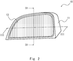
- Fig. 2 is a perspective view showing an example of the display device 10, in which the display device 10 is used for the same purpose as that of a side mirror (left side) of a vehicle.
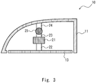
- Fig. 3 is a cross section taken along a cutting line III-III in Fig. 2 , i.e., a cross section as the display device 10 is cut on a horizontal plane.
- Fig. 4 is a cross section taken along a cutting line IV-IV in Fig. 2 , i.e., a cross section as the display device 10 is cut on a vertical plane.
- the housing 11, which is included in the display device 10, houses the display 13. Specifically, the housing 11 houses the display 13 so that the periphery of the display 13 is covered by the housing 11.
- the housing 11 for example, a liquid crystal display device or an organic EL (Electro-Luminescence) display device can be used.
- the housing 11 can be constructed by using a metal material or a resin material.
- a pillar-like member 21 extending in the vertical direction is provided inside the housing 11.
- the display 13 is attached to the pillar-like member 21 by using a connection member 22 that extends from the pillar-like member 21 in the horizontal direction.
- the display 13 may be fixed to the pillar-like member 21 so that a relative positional relation between the display 13 and the pillar-like member 21 is unchanged.
- the display 13 may be attached to the pillar-like member 21 so that the angle of the display 13 as viewed by a driver can be adjusted.
- the pillar-like member 21 is fixed to a base 29 (e.g., fixed to a dashboard of the vehicle).
- the housing 11 is attached to the pillar-like member 21 by using connection members 23 and 24 and a rotation member 25.
- the connection member 23 connects the pillar-like member 21 with the rotation member 25.
- the connection member 24 connects the rotation member 25 with the housing 11.
- the rotation member 25 connects the connection member 23 with the connection member 24 so that relative positions of the connection members 23 and 24 can be changed.
- the housing 11 can be attached to the pillar-like member 21 so that relative positions of the housing 11 and the pillar-like member 21 can be changed. That is, the housing 11 can be displaced independently of the display 13.
- a part of a bottom 26 of the housing 11 is hollowed out so that the housing 11 does not collide with the pillar-like member 21 when the housing 11 is displaced (see the number "27").
- a sensor (not shown in Fig. 4 ) (corresponding to the sensor 12 in Fig. 1 ) for detecting a displacement of the housing 11 relative to the pillar-like member 21, i.e., a relative displacement between the connection members 23 and 24, is provided in the rotation member 25.
- the sensor can be constructed by using a rotary encoder that detects a horizontal displacement of the housing 11 relative to the pillar-like member 21 and another rotary encoder that detects a vertical displacement of the housing 11 relative to the pillar-like member 21. In this way, it is possible to acquire displacement information (e.g., an amount and a direction of a displacement) of the housing 11 relative to the pillar-like member 21.
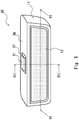
- Fig. 5 is a perspective view showing the display device 30.
- Fig. 6 is a cross section taken along a cutting line VI-VI in Fig. 5 , i.e., a cross section as the display device 30 is cut on a horizontal plane.
- Fig. 7 is a cross section taken along a cutting line VII-VII in Fig. 5 , i.e., a cross section as the display device 30 is cut on a vertical plane.
- the housing 11' which is included in the display device 30, houses the display 13'. Specifically, the housing 11' houses the display 13' so that the periphery of the display 13' is covered by the housing 11'.
- the display 13' for example, a liquid crystal display device or an organic EL display device can be used.
- the housing 11' can be constructed by using a metal material or a resin material.
- a pillar-like member 31 extending in the vertical direction is provided inside the housing 11'.
- the display 13' is attached to the pillar-like member 31 by using a connection member 32 that extends from the pillar-like member 31 in the horizontal direction.
- the display 13' may be fixed to the pillar-like member 31 so that a relative positional relation between the display 13' and the pillar-like member 31 is unchanged.
- the display 13' may be attached to the pillar-like member 31 so that the angle of the display 13' as viewed by a driver can be adjusted.
- the pillar-like member 31 is fixed to a base 39 (e.g., fixed to a front upper part of the vehicle).
- the housing 11' is attached to the pillar-like member 31 by using connection members 33 and 34 and a rotation member 35.
- the connection member 33 connects the pillar-like member 31 with the rotation member 35.
- the connection member 34 connects the rotation member 35 with the housing 11'.
- the rotation member 35 connects the connection member 33 with the connection member 34 so that relative positions of the connection members 33 and 34 can be changed.
- the housing 11' can be attached to the pillar-like member 31 so that relative positions of the housing 11' and the pillar-like member 31 can be changed. That is, the housing 11' can be displaced independently of the display 13'.
- a part of a top part 36 of the housing 11' is hollowed out so that the housing 11' does not collide with the pillar-like member 31 when the housing 11' is displaced (see the number "37").
- a sensor (not shown in Fig. 6 ) (corresponding to the sensor 12 in Fig. 1 ) for detecting a displacement of the housing 11' relative to the pillar-like member 31, i.e., a relative displacement between the connection members 33 and 34, is provided in the rotation member 35.
- the sensor can be constructed by using a rotary encoder that detects a horizontal displacement of the housing 11' relative to the pillar-like member 31 and another rotary encoder that detects a vertical displacement of the housing 11' relative to the pillar-like member 31. In this way, it is possible to acquire displacement information (e.g., an amount and a direction of a displacement) of the housing 11' relative to the pillar-like member 31.
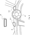
- Fig. 8 shows an example of an arrangement of the display device 10 shown in Figs. 2 to 4 (in Fig. 8 , left and right display devices 10_1 and 10_2 are shown) and the display device 30 shown in Figs. 5 to 7 .
- the left display device 10_1 is disposed on a left side of a dashboard 46 as viewed in a direction toward a steering wheel 45.
- the right display device 10_2 is disposed on a right side of the dashboard 46 as viewed in the direction toward the steering wheel 45.
- the display device 30 is disposed in an upper-front part of the vehicle. Note that the example of the arrangement of the display devices 10_1, 10_2 and 30 shown in Fig. 8 is merely an example. That is, this embodiment may adopt other arrangements.
- Fig. 9 is a top view showing an example of an arrangement of the camera 15. Note that although Fig. 9 shows an example in which three cameras 15a, 15b and 15c are arranged, the number of cameras is not limited to three in this embodiment. The number of display devices is also not limited to any particular number.
- the camera 15a is disposed in a place corresponding to a left side mirror of a vehicle 40.
- the camera 15a shoots, in the surrounding area of the vehicle 40, a left side of the vehicle 40 (its shooting range is indicated by a symbol "50a").
- a video image taken by the camera 15a is displayed in the display device 10_1 shown in Fig. 8 .
- the camera 15b is disposed in a place corresponding to a right side mirror of the vehicle 40.
- the camera 15b shoots, in the surrounding area of the vehicle 40, a right side of the vehicle 40 (its shooting range is indicated by a symbol "50b").
- a video image taken by the camera 15b is displayed in the display device 10_2 shown in Fig. 8 .
- the camera 15c is disposed in a rear part of the vehicle 40.
- the camera 15c shoots, in the surrounding area of the vehicle 40, an area behind the vehicle 40 (its shooting range is indicated by a symbol "50c").
- a video image taken by the camera 15c is displayed in the display device 30 shown in Fig. 8 .
- FIG. 1 An example case in which a video image taken by the camera 15a attached on the left side of the vehicle 40 is displayed in the display device 10_1 disposed inside the vehicle (see Fig. 8 ) is explained hereinafter.
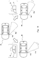
- FIG. 10 An upper part of Fig. 10 shows a case in which the camera 15a shoots a shooting range 50a located on the left side of the vehicle 40. In this case, a video image in a direction corresponding to the shooting range 50a is displayed in the display device 10.
- the shooting range of the camera 15a of the vehicle 40 is changed to a shooting range 51a as shown in a lower-left part of Fig. 10 . That is, the shooting range of the camera 15a is changed in a direction receding from the vehicle.
- the shooting range of the camera 15a of the vehicle 40 is changed to a shooting range 52a as shown in a lower-right part of Fig. 10 . That is, the shooting range of the camera 15a is changed in a direction approaching the vehicle.
- the control unit 14 drives the image pickup unit 17 by using the drive unit 16 so that a video image in a direction corresponding to the direction of the displacement of the housing 11 detected by the sensor 12 is taken by the camera 15a.
- the shooting range of the camera 15a of the vehicle 40 is changed to the shooting ranges 51a and 52a, respectively.
- the video image taken by the image pickup unit 17 is supplied to the display 13 of the display device 10_1 through the control unit 14. As a result, the video image in the direction corresponding to the direction of the displacement of the housing 11 detected by the sensor 12 is displayed on the display 13.
- a case in which the housing 11 is displaced in a clockwise or counterclockwise direction is explained above with reference to Fig. 10 .
- a video image in a direction corresponding to the direction of the displacement of the housing 11 can also be displayed on the display 13 by using the above-described technique.
- a position of the housing 11 in which it has been turned in the clockwise direction as much as possible in a plan view of the housing 11 corresponds to a position of the image pickup unit 17 in which the drive unit 16 has turned the image pickup unit 17 in the clockwise direction as much as possible in a plan view of the image pickup unit 17. That is, in this case, the shooting range 51a of the camera 15a is in an outermost position relative to the vehicle 40 (see the lower-left part of Fig. 10 ).
- a position of the housing 11 in which it has been turned in the counterclockwise direction as much as possible in the plan view of the housing 11 corresponds to a position of the image pickup unit 17 in which the drive unit 16 has turned the image pickup unit 17 in the counterclockwise direction as much as possible in the plan view of the image pickup unit 17. That is, in this case, the shooting range 52a of the camera 15a is in an innermost position relative to the vehicle 40 (see the lower-right part of Fig. 10 ).
- a position of the housing 11 in which it is pointed upward as much as possible i.e., the housing 11 has been turned around the rotation member 25 in a counterclockwise direction as much as possible in Fig. 4 corresponds to a position of the image pickup unit 17 in which the drive unit 16 has turned the image pickup unit 17 upward as much as possible. That is, in this case, the shooting range of the camera 15 is in the most upward direction.
- a position of the housing 11 in which it is pointed downward as much as possible, i.e., the housing 11 has been turned around the rotation member 25 in a clockwise direction as much as possible in Fig. 4 corresponds to a position of the image pickup unit 17 in which the drive unit 16 has turned the image pickup unit 17 downward as much as possible. That is, in this case, the shooting range of the camera 15 is in the most downward direction.
- the display system in which a video image of a surrounding area of the vehicle is taken by using the camera and this video image is displayed on the display disposed inside the vehicle, can reduce (or eliminate) an area that cannot viewed by the driver (i.e., a blind spot), it is effective as a system for improving the safety of the vehicle.
- the housing 11 is configured so that it can be displaced independently of the display 13 and a video image in a direction corresponding to the direction of the displacement of the housing 11 is displayed on the display 13. Therefore, the direction of a video image displayed on the display 13 can be changed just by moving the housing 11, thus making the adjustment of the direction of the video image displayed on the display 13 easier.
- Fig. 11 is a block diagram showing a display system 102 including a display control device 2 according to this embodiment.
- the display control device 2 when a video image in a direction corresponding to the direction of a displacement of the housing 11 is displayed on the display 13, the direction of the video image taken by the image pickup unit 17 is changed by driving the image pickup unit 17 by using the drive unit 16.
- the display control device 2 when a video image in the direction corresponding to a direction of a displacement of the housing 11 is displayed on the display 13, a cut-out place that is cut out from a video image taken by the cameral 62 is changed.
- the display system 102 is similar to the display system 101 including the display control device 1 explained above in the first embodiment. Therefore, the same symbols are assigned to the same components and duplicated explanations are omitted.
- the display system 102 includes a display device 10' and a camera 62.
- the display device 10' incudes a housing 11, a sensor 12, a display 13, and a control unit 61.
- the housing 11, the sensor 12, and the control unit 61 constitute the display control device 2.
- the camera 62 includes an image pickup unit 63. Note that although Fig. 11 shows a configuration example in which the control unit 61 is included in the display device 10', the control unit 61 may be provided separately from the display device 10'.
- the housing 11 is also configured so that it can be displaced independently of the display 13.
- the sensor 12 detects a displacement of the housing 11.
- Information about the displacement of the housing 11 e.g., a direction and an amount of the displacement
- the display 13 displays a video image taken by the camera 62.
- the camera 62 shoots an area surrounding a vehicle. Specifically, the camera 62 shoots the surrounding area of the vehicle by using the image pickup unit 63 included in the camera 62.
- the camera 62 is fixed to a predetermined place of the vehicle and a range (i.e., an angle of view) shot by the camera 62 is fixed to a predetermined range. Therefore, in this embodiment, a camera having a wide angle of view is preferably used as the camera 62.
- the control unit 61 controls a video image displayed on the display 13 so that a video image in a direction corresponding to the direction of the displacement of the housing 11 detected by the sensor 12 is displayed on the display 13. Specifically, the control unit 61 changes a cut-out place that is cut out from a video image taken by the cameral 62 so that the cut-out place corresponds to the direction of the displacement of the housing 11 detected by the sensor 12. That is, the video image taken by the image pickup unit 63 of the camera 62 is supplied to the control unit 61. The control unit 61 cuts out an area of a video image that corresponds to the direction of the displacement of the housing 11 detected by the sensor 12 from the video image supplied from the image pickup unit 63 and supplies the cut-out video image to the display 13. As a result, the video image in the direction corresponding to the direction of the displacement of the housing 11 detected by the sensor 12 is displayed on the display 13.
- Fig. 12 is a top view showing an example of an arrangement of the camera 62. Note that although Fig. 12 shows an example in which three cameras 62a, 62b and 62c are arranged, the number of cameras is not limited to three in this embodiment. The number of display devices 10 is also not limited to any particular number.
- the camera 62a is disposed in a place corresponding to a left side mirror of a vehicle 43.
- the camera 62a shoots, in the surrounding area of the vehicle 43, a left side of the vehicle 43 (its shooting range is indicated by a symbol "55a").
- a video image taken by the camera 62a is displayed in the display device 10_1 shown in Fig. 8 .
- the camera 62b is disposed in a place corresponding to a right side mirror of the vehicle 43.
- the camera 62b shoots, in the surrounding area of the vehicle 43, a right side of the vehicle 43 (its shooting range is indicated by a symbol "55b").
- a video image taken by the camera 62b is displayed in the display device 10_2 shown in Fig. 8 .
- the camera 62c is disposed in a rear part of the vehicle 43.
- the camera 62c shoots, in the surrounding area of the vehicle 43, an area behind the vehicle 43 (its shooting range is indicated by a symbol "55c").
- a video image taken by the camera 62c is displayed in the display device 30 shown in Fig. 8 .
- the camera 62 is fixed to the vehicle and hence the image pickup unit 63 is not displaced. Therefore, the ranges shot the cameras 62a, 62b and 62c are fixed to the shooting ranges 55a, 55b and 55c, respectively. Therefore, in this embodiment, a camera having a wide angle of view is preferably used as each of the cameras 62a, 62b and 62c.
- the shooting ranges 55a, 55b and 55c of the cameras 62a, 62b and 62c, respectively, shown in Fig. 12 are wider than the shooting ranges 50a, 50b and 50c of the cameras 15a, 15b and 15c, respectively, shown in Fig. 9 .
- FIG. 11 An example case in which a video image taken by the camera 62a attached on the left side of the vehicle 43 (see Fig. 12 ) is displayed in the display device 10_1 disposed inside the vehicle (see Fig. 8 ) is explained hereinafter.
- a video image taken by the camera 62a is indicated by a number "70".
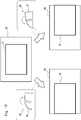
- FIG. 13 shows a case in which a central part of a video image 70 taken by the camera 62a is defined as a cut-out place 71.
- a video image in the cut-out place 71 is displayed in the display device 10'.
- the control unit 61 shifts the cut-out place in the video image 70 taken by the camera 62a to the left so that the cut-out place corresponds to the direction of the displacement of the housing 11 as shown in a lower-left part of Fig. 13 . That is, the cut-out place is shifted to the side farther from the vehicle.
- the control unit 61 defines a left part of the video image 70 taken by the camera 62a as a cut-out place 72. In this case, a video image in the cut-out place 72 is displayed in the display device 10'.
- the control unit 61 shifts the cut-out place in the video image 70 taken by the camera 62a to the right so that the cut-out place corresponds to the direction of the displacement of the housing 11 as shown in a lower-right part of Fig. 13 . That is, the cut-out place is shifted to the side closer to the vehicle.
- the control unit 61 defines a right part of the video image 70 taken by the camera 62a as a cut-out place 73. In this case, a video image in the cut-out place 73 is displayed in the display device 10'.
- the sensor 12 (see Fig. 11 ) attached to the rotation member 25 (see Fig. 3 ) detects the displacement of the housing 11 and supplies information about this displacement to the control unit 61.
- the control unit 61 cuts out a video image in a direction corresponding to the direction of the displacement of the housing 11 detected by the sensor 12 and supplies the cut-out video image to the display 13. As a result, the video image in the direction corresponding to the direction of the displacement of the housing 11 detected by the sensor 12 is displayed on the display 13.
- a case in which the housing 11 is displaced in a clockwise or counterclockwise direction is explained above with reference to Fig. 13 .
- a video image in a direction corresponding to the direction of the displacement of the housing 11 can also be displayed on the display 13 by using the above-described technique.
- a position of the housing 11 in which it has been turned in the clockwise direction as much as possible in a plan view of the housing 11 corresponds a cut-out place 72 located in a left-end part of the video image 70 taken by the camera 62a (see the lower-left part of Fig. 13 ).
- a position of the housing 11 in which it has been turned in the counterclockwise direction as much as possible in the plan view of the housing 11 corresponds a cut-out place 73 located in a right-end part of the video image 70 taken by the camera 62a (see the lower-right part of Fig. 13 ).
- a position of the housing 11 in which it is pointed upward as much as possible, i.e., the housing 11 has been turned around the rotation member 25 in a counterclockwise direction as much as possible in Fig. 4 corresponds to a state in which an upper-end part of the video image 70 taken by the camera 62a is defined as the cut-out place.
- a position of the housing 11 in which it is pointed downward as much as possible, i.e., the housing 11 has been turned around the rotation member 25 in a clockwise direction as much as possible in Fig. 4 corresponds to a state in which a lower-end part of the video image 70 taken by the camera 62a is defined as the cut-out place.
- Fig. 14 is a cross section showing another configuration example of a display device.
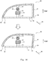
- a display device 80 when a display device 80 is constructed, it may be configured so that an end 84 of a housing 81 adjacent to an end 82 of a display 13, which is one of the ends 82 and 83 of the display 13 in the horizontal direction closer to a driver, is disposed closer to the front of the vehicle. That is, in a plan view of the housing 81, the end 84 of the housing 81 may be disposed closer to the front of the vehicle than the other end 85 of the housing 81 located farther from the driver is. Note that an arrow 89 indicates the direction of driver's line of sight.
- the end of the display 13 on the right side in the figure could be concealed by the end of the housing 11 on the right side in the figure.
- the end 84 of the housing 81 in the plan view of the housing 81, is disposed closer to the front of the vehicle. In other words, the end 84 of the housing 81 is disposed closer to the front of the vehicle than the end 82 of the display 13 is. Therefore, as shown in a lower part of Fig.
- the display control devices 1 and 2 may be configured so that when the vehicle is in a stopped state, the direction of a video image displayed on the display 13 can be changed to a direction corresponding to the direction of a displacement of the housing 11 detected by the sensor 12, whereas when the vehicle is traveling, such a change in the video image cannot be performed.
- the housing may be locked to prevent the movement thereof so that the change in the video image cannot be performed.
- the present disclosure can be suitably applied to, for example, a display control device and a display system that can be mounted in a vehicle.
Landscapes
- Engineering & Computer Science (AREA)
- Multimedia (AREA)
- Signal Processing (AREA)
- Mechanical Engineering (AREA)
- Physics & Mathematics (AREA)
- Computer Hardware Design (AREA)
- General Physics & Mathematics (AREA)
- Theoretical Computer Science (AREA)
- Controls And Circuits For Display Device (AREA)
- Fittings On The Vehicle Exterior For Carrying Loads, And Devices For Holding Or Mounting Articles (AREA)
- Closed-Circuit Television Systems (AREA)
Abstract
Description
- The present disclosure relates to a display control device and a display system, and in particular to a display control device and a display system that display a video image taken by a camera on a display.
- A vehicle surroundings monitoring system in which a camera attached to a vehicle takes a video image of an area surrounding the vehicle and the taken video image is displayed on a display in order to draw the attention of a driver driving the vehicle has been under development.
- For example,
Patent Literature 1 discloses a vehicle surroundings monitoring system capable of allowing a driver to easily recognize a series of moving states of a vehicle that is trying to pass his/her own vehicle from behind. In the technique disclosed inPatent Literature 1, a video image of an area surrounding the vehicle is taken by using a camera attached to the vehicle and this taken video image is displayed on a display disposed inside the vehicle. - Patent Literature 1: Japanese Unexamined Patent Application Publication No.
2010-64646 - Since a display system, in which a video image of an area surrounding a vehicle is taken by using a camera and this taken video image is displayed on a display disposed inside the vehicle, can reduce (or eliminate) an area that cannot be viewed by the driver (i.e., a blind spot), it is effective as a system for improving the safety of the vehicle.
- In such a display system, it is necessary to adjust the direction in which the camera performs shooting so that a video image required by the driver is displayed on the display. For example, the driver needs to adjust the direction in which the camera performs shooting and thereby adjust the direction of the video image displayed on the display before driving the vehicle. However, as the adjustment of the direction of the video image displayed on the display becomes complicated, there is a problem that it takes a long time to adjust the direction of the video image.
- In view of the above-described problem, an object of the present disclosure is to provide a display control device and a display system capable of easily changing the direction of a video image displayed on a display.
- A display control device according to an embodiment includes: a housing configured to house a display on which a video image taken by a camera is displayed and be able to be displaced independently of the display; a sensor configured to detect a displacement of the housing; and a control unit configured to control a video image displayed on the display so that a video image in a direction corresponding to a direction of the displacement of the housing detected by the sensor is displayed on the display.
- According to this embodiment, it is possible to provide a display control device and a display system capable of easily changing the direction of a video image displayed on a display.
-
-
Fig. 1 is a block diagram showing a display system including a display control device according to a first embodiment; -
Fig. 2 is a perspective view showing an example of a display device; -
Fig. 3 is a cross section taken along a cutting line III-III inFig. 2 ; -
Fig. 4 is a cross section taken along a cutting line IV-IV inFig. 2 ; -
Fig. 5 is a perspective view showing another configuration example of a display device; -
Fig. 6 is a cross section taken along a cutting line VI-VI inFig. 5 ; -
Fig. 7 is a cross section taken along a cutting line VII-VII inFig. 5 ; -
Fig. 8 shows an example of an arrangement of display devices; -
Fig. 9 shows an example of an arrangement of cameras; -
Fig. 10 is a diagram for explaining an operation of the display control device according to the first embodiment; -
Fig. 11 is a block diagram showing a display system including a display control device according to a second embodiment; -
Fig. 12 is a top view showing an example of an arrangement of cameras; -
Fig. 13 is a diagram for explaining an operation of the display control device according to the second embodiment; and -
Fig. 14 is a cross section showing another configuration example of a display device. - Embodiments according to the present disclosure are explained hereinafter with reference to the drawings.
Fig. 1 is a block diagram showing adisplay system 101 including adisplay control device 1 according to a first embodiment. As shown inFig. 1 , thedisplay system 101 includes adisplay device 10 and acamera 15. Thedisplay device 10 includes ahousing 11, asensor 12, adisplay 13, and acontrol unit 14. Note that thehousing 11, thesensor 12, and thecontrol unit 14 constitute thedisplay control device 1. Thecamera 15 includes adrive unit 16 and animage pickup unit 17. Note that althoughFig. 1 shows a configuration example in which thecontrol unit 14 is included in thedisplay device 10, thecontrol unit 14 may be provided separately from thedisplay device 10. - The
housing 11, which is included in thedisplay device 10, houses thedisplay 13. Further, thehousing 11 is configured so that it can be displaced independently of the display 13 (details of the structure are described later). Thesensor 12 detects a displacement of thehousing 11. Information about the displacement of the housing 11 (e.g., a direction and an amount of the displacement) detected by thesensor 12 is supplied to thecontrol unit 14. Thedisplay 13 displays a video image taken by thecamera 15. - The
camera 15 takes a video image of an area where thecamera 15 is disposed. Specifically, thecamera 15 takes a video image by using theimage pickup unit 17. Further, thedrive unit 16 drives theimage pickup unit 17 and changes the direction of the video image taken by theimage pickup unit 17. - The
control unit 14 controls a video image displayed on thedisplay 13 so that a video image in a direction corresponding to the direction of the displacement of thehousing 11 detected by thesensor 12 is displayed on thedisplay 13. Specifically, thecontrol unit 14 controls thedrive unit 16 so that a video image in a direction corresponding to the direction of the displacement of thehousing 11 detected by thesensor 12 is taken by theimage pickup unit 17. The video image taken by theimage pickup unit 17 is supplied to thedisplay 13 through thecontrol unit 14. In this way, the video image in the direction corresponding to the direction of the displacement of thehousing 11 detected by thesensor 12 is displayed on thedisplay 13. - The
display control device 1 according to this embodiment can be used, for example, for a display system that takes a video image of an area surrounding a vehicle by using a camera and displays this taken video image on a display. As an example, a case in which an invention according to this embodiment is applied to a vehicle-mounted display system is explained hereinafter. However, the invention according to this embodiment can be applied to a display system or the like other than the vehicle-mounted display system. -
Fig. 2 is a perspective view showing an example of thedisplay device 10, in which thedisplay device 10 is used for the same purpose as that of a side mirror (left side) of a vehicle. Further,Fig. 3 is a cross section taken along a cutting line III-III inFig. 2 , i.e., a cross section as thedisplay device 10 is cut on a horizontal plane.Fig. 4 is a cross section taken along a cutting line IV-IV inFig. 2 , i.e., a cross section as thedisplay device 10 is cut on a vertical plane. - As shown in
Figs. 2 to 4 , thehousing 11, which is included in thedisplay device 10, houses thedisplay 13. Specifically, thehousing 11 houses thedisplay 13 so that the periphery of thedisplay 13 is covered by thehousing 11. For thedisplay 13, for example, a liquid crystal display device or an organic EL (Electro-Luminescence) display device can be used. Further, thehousing 11 can be constructed by using a metal material or a resin material. - As shown in
Figs. 3 and4 , a pillar-like member 21 extending in the vertical direction is provided inside thehousing 11. Thedisplay 13 is attached to the pillar-like member 21 by using aconnection member 22 that extends from the pillar-like member 21 in the horizontal direction. Note that thedisplay 13 may be fixed to the pillar-like member 21 so that a relative positional relation between thedisplay 13 and the pillar-like member 21 is unchanged. Further, thedisplay 13 may be attached to the pillar-like member 21 so that the angle of thedisplay 13 as viewed by a driver can be adjusted. The pillar-like member 21 is fixed to a base 29 (e.g., fixed to a dashboard of the vehicle). - The
housing 11 is attached to the pillar-like member 21 by usingconnection members rotation member 25. Specifically, theconnection member 23 connects the pillar-like member 21 with therotation member 25. Theconnection member 24 connects therotation member 25 with thehousing 11. Therotation member 25 connects theconnection member 23 with theconnection member 24 so that relative positions of theconnection members housing 11 can be attached to the pillar-like member 21 so that relative positions of thehousing 11 and the pillar-like member 21 can be changed. That is, thehousing 11 can be displaced independently of thedisplay 13. As shown inFig. 4 , a part of a bottom 26 of thehousing 11 is hollowed out so that thehousing 11 does not collide with the pillar-like member 21 when thehousing 11 is displaced (see the number "27"). - A sensor (not shown in
Fig. 4 ) (corresponding to thesensor 12 inFig. 1 ) for detecting a displacement of thehousing 11 relative to the pillar-like member 21, i.e., a relative displacement between theconnection members rotation member 25. For example, the sensor can be constructed by using a rotary encoder that detects a horizontal displacement of thehousing 11 relative to the pillar-like member 21 and another rotary encoder that detects a vertical displacement of thehousing 11 relative to the pillar-like member 21. In this way, it is possible to acquire displacement information (e.g., an amount and a direction of a displacement) of thehousing 11 relative to the pillar-like member 21. - Next, as another configuration example of the
display device 10 shown inFig. 1 , adisplay device 30 that is used for the same purpose as that of a rearview mirror of a vehicle is explained with reference toFigs. 5 to 7 .Fig. 5 is a perspective view showing thedisplay device 30.Fig. 6 is a cross section taken along a cutting line VI-VI inFig. 5 , i.e., a cross section as thedisplay device 30 is cut on a horizontal plane.Fig. 7 is a cross section taken along a cutting line VII-VII inFig. 5 , i.e., a cross section as thedisplay device 30 is cut on a vertical plane. - As shown in
Figs. 5 to 7 , the housing 11', which is included in thedisplay device 30, houses the display 13'. Specifically, the housing 11' houses the display 13' so that the periphery of the display 13' is covered by the housing 11'. For the display 13', for example, a liquid crystal display device or an organic EL display device can be used. Further, the housing 11' can be constructed by using a metal material or a resin material. - As shown in
Figs. 6 and7 , a pillar-like member 31 extending in the vertical direction is provided inside the housing 11'. The display 13' is attached to the pillar-like member 31 by using aconnection member 32 that extends from the pillar-like member 31 in the horizontal direction. Note that the display 13' may be fixed to the pillar-like member 31 so that a relative positional relation between the display 13' and the pillar-like member 31 is unchanged. Further, the display 13' may be attached to the pillar-like member 31 so that the angle of the display 13' as viewed by a driver can be adjusted. The pillar-like member 31 is fixed to a base 39 (e.g., fixed to a front upper part of the vehicle). - The housing 11' is attached to the pillar-
like member 31 by usingconnection members rotation member 35. Specifically, theconnection member 33 connects the pillar-like member 31 with therotation member 35. Theconnection member 34 connects therotation member 35 with the housing 11'. Therotation member 35 connects theconnection member 33 with theconnection member 34 so that relative positions of theconnection members like member 31 so that relative positions of the housing 11' and the pillar-like member 31 can be changed. That is, the housing 11' can be displaced independently of the display 13'. As shown inFig. 7 , a part of atop part 36 of the housing 11' is hollowed out so that the housing 11' does not collide with the pillar-like member 31 when the housing 11' is displaced (see the number "37"). - A sensor (not shown in
Fig. 6 ) (corresponding to thesensor 12 inFig. 1 ) for detecting a displacement of the housing 11' relative to the pillar-like member 31, i.e., a relative displacement between theconnection members rotation member 35. For example, the sensor can be constructed by using a rotary encoder that detects a horizontal displacement of the housing 11' relative to the pillar-like member 31 and another rotary encoder that detects a vertical displacement of the housing 11' relative to the pillar-like member 31. In this way, it is possible to acquire displacement information (e.g., an amount and a direction of a displacement) of the housing 11' relative to the pillar-like member 31. -
Fig. 8 shows an example of an arrangement of thedisplay device 10 shown inFigs. 2 to 4 (inFig. 8 , left and right display devices 10_1 and 10_2 are shown) and thedisplay device 30 shown inFigs. 5 to 7 . The left display device 10_1 is disposed on a left side of adashboard 46 as viewed in a direction toward asteering wheel 45. The right display device 10_2 is disposed on a right side of thedashboard 46 as viewed in the direction toward thesteering wheel 45. Thedisplay device 30 is disposed in an upper-front part of the vehicle. Note that the example of the arrangement of the display devices 10_1, 10_2 and 30 shown inFig. 8 is merely an example. That is, this embodiment may adopt other arrangements. - Next, an example of an arrangement of the
camera 15 shown inFig. 1 is explained.Fig. 9 is a top view showing an example of an arrangement of thecamera 15. Note that althoughFig. 9 shows an example in which threecameras - As shown in
Fig. 9 , thecamera 15a is disposed in a place corresponding to a left side mirror of avehicle 40. Thecamera 15a shoots, in the surrounding area of thevehicle 40, a left side of the vehicle 40 (its shooting range is indicated by a symbol "50a"). A video image taken by thecamera 15a is displayed in the display device 10_1 shown inFig. 8 . Similarly, thecamera 15b is disposed in a place corresponding to a right side mirror of thevehicle 40. Thecamera 15b shoots, in the surrounding area of thevehicle 40, a right side of the vehicle 40 (its shooting range is indicated by a symbol "50b"). A video image taken by thecamera 15b is displayed in the display device 10_2 shown inFig. 8 . Thecamera 15c is disposed in a rear part of thevehicle 40. Thecamera 15c shoots, in the surrounding area of thevehicle 40, an area behind the vehicle 40 (its shooting range is indicated by a symbol "50c"). A video image taken by thecamera 15c is displayed in thedisplay device 30 shown inFig. 8 . - Next, an operation of the
display control device 1 according to this embodiment is explained with reference toFigs. 1 and10 . An example case in which a video image taken by thecamera 15a attached on the left side of thevehicle 40 is displayed in the display device 10_1 disposed inside the vehicle (seeFig. 8 ) is explained hereinafter. - An upper part of
Fig. 10 shows a case in which thecamera 15a shoots ashooting range 50a located on the left side of thevehicle 40. In this case, a video image in a direction corresponding to theshooting range 50a is displayed in thedisplay device 10. - When the
housing 11 of thedisplay device 10 is turned in a clockwise direction as viewed from above thevehicle 40, the shooting range of thecamera 15a of thevehicle 40 is changed to ashooting range 51a as shown in a lower-left part ofFig. 10 . That is, the shooting range of thecamera 15a is changed in a direction receding from the vehicle. Alternatively, when thehousing 11 of thedisplay device 10 is turned in a counterclockwise direction, the shooting range of thecamera 15a of thevehicle 40 is changed to ashooting range 52a as shown in a lower-right part ofFig. 10 . That is, the shooting range of thecamera 15a is changed in a direction approaching the vehicle. - That is, when the
housing 11 of thedisplay device 10 is displaced, the sensor 12 (seeFig. 1 ) attached to the rotation member 25 (seeFig. 3 ) detects the displacement of thehousing 11 and supplies information about this displacement to thecontrol unit 14. Thecontrol unit 14 drives theimage pickup unit 17 by using thedrive unit 16 so that a video image in a direction corresponding to the direction of the displacement of thehousing 11 detected by thesensor 12 is taken by thecamera 15a. As a result, the shooting range of thecamera 15a of thevehicle 40 is changed to theshooting ranges image pickup unit 17 is supplied to thedisplay 13 of the display device 10_1 through thecontrol unit 14. As a result, the video image in the direction corresponding to the direction of the displacement of thehousing 11 detected by thesensor 12 is displayed on thedisplay 13. - Note that a case in which the
housing 11 is displaced in a clockwise or counterclockwise direction is explained above with reference toFig. 10 . However, in thedisplay control device 1 according to this embodiment, when thehousing 11 is moved in the vertical direction as viewed by the driver, a video image in a direction corresponding to the direction of the displacement of thehousing 11 can also be displayed on thedisplay 13 by using the above-described technique. - Further, for example, a position of the
housing 11 in which it has been turned in the clockwise direction as much as possible in a plan view of thehousing 11 corresponds to a position of theimage pickup unit 17 in which thedrive unit 16 has turned theimage pickup unit 17 in the clockwise direction as much as possible in a plan view of theimage pickup unit 17. That is, in this case, theshooting range 51a of thecamera 15a is in an outermost position relative to the vehicle 40 (see the lower-left part ofFig. 10 ). Similarly, for example, a position of thehousing 11 in which it has been turned in the counterclockwise direction as much as possible in the plan view of thehousing 11 corresponds to a position of theimage pickup unit 17 in which thedrive unit 16 has turned theimage pickup unit 17 in the counterclockwise direction as much as possible in the plan view of theimage pickup unit 17. That is, in this case, theshooting range 52a of thecamera 15a is in an innermost position relative to the vehicle 40 (see the lower-right part ofFig. 10 ). - Note that an operation that is performed when the
housing 11 is moved in the vertical direction as viewed by the driver is similar to the above-described operation. That is, a position of thehousing 11 in which it is pointed upward as much as possible, i.e., thehousing 11 has been turned around therotation member 25 in a counterclockwise direction as much as possible inFig. 4 corresponds to a position of theimage pickup unit 17 in which thedrive unit 16 has turned theimage pickup unit 17 upward as much as possible. That is, in this case, the shooting range of thecamera 15 is in the most upward direction. Further, a position of thehousing 11 in which it is pointed downward as much as possible, i.e., thehousing 11 has been turned around therotation member 25 in a clockwise direction as much as possible inFig. 4 corresponds to a position of theimage pickup unit 17 in which thedrive unit 16 has turned theimage pickup unit 17 downward as much as possible. That is, in this case, the shooting range of thecamera 15 is in the most downward direction. - As explained above in the Background section, since the display system, in which a video image of a surrounding area of the vehicle is taken by using the camera and this video image is displayed on the display disposed inside the vehicle, can reduce (or eliminate) an area that cannot viewed by the driver (i.e., a blind spot), it is effective as a system for improving the safety of the vehicle.
- In such a display system, it is necessary to adjust the direction in which the camera performs shooting so that a video image required by the driver is displayed on the display. For example, the driver needs to adjust the direction in which the camera performs shooting and thereby adjust the direction of the video image displayed on the display before driving the vehicle. However, when the adjustment of the direction of the video image displayed on the display is complicated, there is a problem that it takes a long time for the adjustment of the direction of the video image.
- Therefore, in the
display control device 1 according to this embodiment, thehousing 11 is configured so that it can be displaced independently of thedisplay 13 and a video image in a direction corresponding to the direction of the displacement of thehousing 11 is displayed on thedisplay 13. Therefore, the direction of a video image displayed on thedisplay 13 can be changed just by moving thehousing 11, thus making the adjustment of the direction of the video image displayed on thedisplay 13 easier. - According to an invention in accordance with this embodiment explained above, it is possible to provide a display control device capable of easily changing the direction of a video image displayed on a display.
- Next, a second embodiment according to the present disclosure is explained.
Fig. 11 is a block diagram showing adisplay system 102 including adisplay control device 2 according to this embodiment. In the above-described first embodiment (seeFig. 1 ), when a video image in a direction corresponding to the direction of a displacement of thehousing 11 is displayed on thedisplay 13, the direction of the video image taken by theimage pickup unit 17 is changed by driving theimage pickup unit 17 by using thedrive unit 16. In contrast to this, in thedisplay control device 2 according to this embodiment, when a video image in the direction corresponding to a direction of a displacement of thehousing 11 is displayed on thedisplay 13, a cut-out place that is cut out from a video image taken by the cameral 62 is changed. Except for this difference, thedisplay system 102 is similar to thedisplay system 101 including thedisplay control device 1 explained above in the first embodiment. Therefore, the same symbols are assigned to the same components and duplicated explanations are omitted. - As shown in
Fig. 11 , thedisplay system 102 includes a display device 10' and acamera 62. The display device 10' incudes ahousing 11, asensor 12, adisplay 13, and acontrol unit 61. Note that thehousing 11, thesensor 12, and thecontrol unit 61 constitute thedisplay control device 2. Thecamera 62 includes animage pickup unit 63. Note that althoughFig. 11 shows a configuration example in which thecontrol unit 61 is included in the display device 10', thecontrol unit 61 may be provided separately from the display device 10'. - In this embodiment, the
housing 11 is also configured so that it can be displaced independently of thedisplay 13. Thesensor 12 detects a displacement of thehousing 11. Information about the displacement of the housing 11 (e.g., a direction and an amount of the displacement) detected by thesensor 12 is supplied to thecontrol unit 61. Thedisplay 13 displays a video image taken by thecamera 62. - The
camera 62 shoots an area surrounding a vehicle. Specifically, thecamera 62 shoots the surrounding area of the vehicle by using theimage pickup unit 63 included in thecamera 62. Thecamera 62 is fixed to a predetermined place of the vehicle and a range (i.e., an angle of view) shot by thecamera 62 is fixed to a predetermined range. Therefore, in this embodiment, a camera having a wide angle of view is preferably used as thecamera 62. - The
control unit 61 controls a video image displayed on thedisplay 13 so that a video image in a direction corresponding to the direction of the displacement of thehousing 11 detected by thesensor 12 is displayed on thedisplay 13. Specifically, thecontrol unit 61 changes a cut-out place that is cut out from a video image taken by the cameral 62 so that the cut-out place corresponds to the direction of the displacement of thehousing 11 detected by thesensor 12. That is, the video image taken by theimage pickup unit 63 of thecamera 62 is supplied to thecontrol unit 61. Thecontrol unit 61 cuts out an area of a video image that corresponds to the direction of the displacement of thehousing 11 detected by thesensor 12 from the video image supplied from theimage pickup unit 63 and supplies the cut-out video image to thedisplay 13. As a result, the video image in the direction corresponding to the direction of the displacement of thehousing 11 detected by thesensor 12 is displayed on thedisplay 13. -
Fig. 12 is a top view showing an example of an arrangement of thecamera 62. Note that althoughFig. 12 shows an example in which threecameras display devices 10 is also not limited to any particular number. - As shown in
Fig. 12 , thecamera 62a is disposed in a place corresponding to a left side mirror of avehicle 43. Thecamera 62a shoots, in the surrounding area of thevehicle 43, a left side of the vehicle 43 (its shooting range is indicated by a symbol "55a"). A video image taken by thecamera 62a is displayed in the display device 10_1 shown inFig. 8 . Similarly, thecamera 62b is disposed in a place corresponding to a right side mirror of thevehicle 43. Thecamera 62b shoots, in the surrounding area of thevehicle 43, a right side of the vehicle 43 (its shooting range is indicated by a symbol "55b"). A video image taken by thecamera 62b is displayed in the display device 10_2 shown inFig. 8 . Thecamera 62c is disposed in a rear part of thevehicle 43. Thecamera 62c shoots, in the surrounding area of thevehicle 43, an area behind the vehicle 43 (its shooting range is indicated by a symbol "55c"). A video image taken by thecamera 62c is displayed in thedisplay device 30 shown inFig. 8 . - In this embodiment, the
camera 62 is fixed to the vehicle and hence theimage pickup unit 63 is not displaced. Therefore, the ranges shot thecameras shooting ranges cameras shooting ranges cameras Fig. 12 are wider than theshooting ranges cameras Fig. 9 . - Next, an operation of the
display control device 2 according to this embodiment is explained with reference toFigs. 11 to 13 . An example case in which a video image taken by thecamera 62a attached on the left side of the vehicle 43 (seeFig. 12 ) is displayed in the display device 10_1 disposed inside the vehicle (seeFig. 8 ) is explained hereinafter. InFig. 13 , a video image taken by thecamera 62a is indicated by a number "70". - An upper part of
Fig. 13 shows a case in which a central part of avideo image 70 taken by thecamera 62a is defined as a cut-out place 71. In this case, a video image in the cut-out place 71 is displayed in the display device 10'. - When the
housing 11 of the display device 10' is turned in a clockwise direction as viewed from above thevehicle 43, thecontrol unit 61 shifts the cut-out place in thevideo image 70 taken by thecamera 62a to the left so that the cut-out place corresponds to the direction of the displacement of thehousing 11 as shown in a lower-left part ofFig. 13 . That is, the cut-out place is shifted to the side farther from the vehicle. For example, thecontrol unit 61 defines a left part of thevideo image 70 taken by thecamera 62a as a cut-out place 72. In this case, a video image in the cut-out place 72 is displayed in the display device 10'. - Similarly, when the
housing 11 of the display device 10' is turned in a counterclockwise direction, thecontrol unit 61 shifts the cut-out place in thevideo image 70 taken by thecamera 62a to the right so that the cut-out place corresponds to the direction of the displacement of thehousing 11 as shown in a lower-right part ofFig. 13 . That is, the cut-out place is shifted to the side closer to the vehicle. For example, thecontrol unit 61 defines a right part of thevideo image 70 taken by thecamera 62a as a cut-out place 73. In this case, a video image in the cut-out place 73 is displayed in the display device 10'. - That is, when the
housing 11 of the display device 10' is displaced, the sensor 12 (seeFig. 11 ) attached to the rotation member 25 (seeFig. 3 ) detects the displacement of thehousing 11 and supplies information about this displacement to thecontrol unit 61. Thecontrol unit 61 cuts out a video image in a direction corresponding to the direction of the displacement of thehousing 11 detected by thesensor 12 and supplies the cut-out video image to thedisplay 13. As a result, the video image in the direction corresponding to the direction of the displacement of thehousing 11 detected by thesensor 12 is displayed on thedisplay 13. - Note that a case in which the
housing 11 is displaced in a clockwise or counterclockwise direction is explained above with reference toFig. 13 . However, in thedisplay control device 2 according to this embodiment, when thehousing 11 is moved in the vertical direction as viewed by the driver, a video image in a direction corresponding to the direction of the displacement of thehousing 11 can also be displayed on thedisplay 13 by using the above-described technique. - Further, for example, a position of the
housing 11 in which it has been turned in the clockwise direction as much as possible in a plan view of thehousing 11 corresponds a cut-out place 72 located in a left-end part of thevideo image 70 taken by thecamera 62a (see the lower-left part ofFig. 13 ). Similarly, for example, a position of thehousing 11 in which it has been turned in the counterclockwise direction as much as possible in the plan view of thehousing 11 corresponds a cut-out place 73 located in a right-end part of thevideo image 70 taken by thecamera 62a (see the lower-right part ofFig. 13 ). - Note that an operation that is performed when the
housing 11 is moved in the vertical direction as viewed by the driver is similar to the above-described operation. That is, a position of thehousing 11 in which it is pointed upward as much as possible, i.e., thehousing 11 has been turned around therotation member 25 in a counterclockwise direction as much as possible inFig. 4 corresponds to a state in which an upper-end part of thevideo image 70 taken by thecamera 62a is defined as the cut-out place. Further, a position of thehousing 11 in which it is pointed downward as much as possible, i.e., thehousing 11 has been turned around therotation member 25 in a clockwise direction as much as possible inFig. 4 corresponds to a state in which a lower-end part of thevideo image 70 taken by thecamera 62a is defined as the cut-out place. - According to an invention in accordance with this embodiment explained above, it is possible to provide a display control device capable of easily changing the direction of a video image displayed on a display.
- Next, other embodiments are explained.
Fig. 14 is a cross section showing another configuration example of a display device. In this embodiment, as shown in an upper part ofFig. 14 , when adisplay device 80 is constructed, it may be configured so that anend 84 of ahousing 81 adjacent to anend 82 of adisplay 13, which is one of theends display 13 in the horizontal direction closer to a driver, is disposed closer to the front of the vehicle. That is, in a plan view of thehousing 81, theend 84 of thehousing 81 may be disposed closer to the front of the vehicle than theother end 85 of thehousing 81 located farther from the driver is. Note that anarrow 89 indicates the direction of driver's line of sight. - That is, in the
display device 10 shown inFig. 3 , when thehousing 11 is turned in a clockwise direction, the end of thedisplay 13 on the right side in the figure could be concealed by the end of thehousing 11 on the right side in the figure. In contrast to this, in thedisplay device 80 shown inFig. 14 , in the plan view of thehousing 81, theend 84 of thehousing 81 is disposed closer to the front of the vehicle. In other words, theend 84 of thehousing 81 is disposed closer to the front of the vehicle than theend 82 of thedisplay 13 is. Therefore, as shown in a lower part ofFig. 14 , it is possible to prevent theend 82 of thedisplay 13 from being concealed by theend 84 of thehousing 81 when thehousing 81 is turned in the clockwise direction. Note that the above-described configuration can also be applied to thedisplay device 30 shown inFigs. 5 to 7 in a similar manner. - Further, the
display control devices display 13 can be changed to a direction corresponding to the direction of a displacement of thehousing 11 detected by thesensor 12, whereas when the vehicle is traveling, such a change in the video image cannot be performed. For example, the housing may be locked to prevent the movement thereof so that the change in the video image cannot be performed. By adopting the above-described configuration, it is possible to prevent a driver from manipulating thehousing 11 while he/she is driving the vehicle and thereby to improve the safety. - The present invention has been explained above with the above-described embodiments. However, the present invention is not limited to the above-described embodiments, and needless to say, various modifications, corrections, and combinations that can be made by those skilled in the art are also included in the scope of the present invention specified in the claims of the present application.
- This application is based upon and claims the benefit of priority from Japanese patent application No.
2015-024393 filed on February 10, 2015 - The present disclosure can be suitably applied to, for example, a display control device and a display system that can be mounted in a vehicle.
-
- 1, 2 DISPLAY CONTROL DEVICE
- 10, 10', 30 DISPLAY DEVICE
- 11 HOUSING
- 12 SENSOR
- 13 DISPLAY
- 14,61 CONTROL UNIT
- 15,62 CAMERA
- 16 DRIVE UNIT
- 17, 63 IMAGE PICKUP UNIT
- 101, 102 DISPLAY SYSTEM
Claims (9)
- A display control device comprising:a housing configured to house a display on which a video image taken by a camera is displayed and be able to be displaced independently of the display;a sensor configured to detect a displacement of the housing; anda control unit configured to control a video image displayed on the display so that a video image in a direction corresponding to a direction of the displacement of the housing detected by the sensor is displayed on the display.
- The display control device according to Claim 1, wherein
the camera comprises an image pickup unit, and a drive unit configured to change a direction of a video image taken by the image pickup unit by driving the image pickup unit, and
the control unit controls the drive unit so that a video image in a direction corresponding to a direction of a displacement of the housing detected by the sensor is taken by the image pickup unit, and thereby controls a video image displayed on the display. - The display control device according to Claim 2, wherein
a position of the housing in which the housing is turned in a clockwise direction as much as possible in a plan view of the housing corresponds to a position of the image pickup unit in which the drive unit turns the image pickup unit in a clockwise direction as much as possible in a plan view of the image pickup unit, and
a position of the housing in which the housing is turned in a counterclockwise direction as much as possible in the plan view of the housing corresponds to a position of the image pickup unit in which the drive unit turns the image pickup unit in a counterclockwise direction as much as possible in the plan view of the image pickup unit. - The display control device according to Claim 1, wherein the control unit changes a cut-out place that is cut out from a video image taken by the camera so that the cut-out place corresponds to a direction of a displacement of the housing detected by the sensor, and thereby controls a video image displayed on the display.
- The display control device according to Claim 4, wherein
a position of the housing in which the housing is turned in a clockwise direction as much as possible in a plan view of the housing corresponds to a cut-out place located in a left-end part of the video image taken by the camera, and
a position of the housing in which the housing is turned in a counterclockwise direction as much as possible in the plan view of the housing corresponds to a cut-out place located in a right-end part of the video image taken by the camera. - The display control device according to any one of Claims 1 to 5, wherein, in a plan view of the housing, an end of the housing adjacent to one of ends of the display in a horizontal direction is disposed closer to a front than another end of the housing adjacent to another end of the display in the horizontal direction is.
- The display control device according to Claim 6, wherein
the display is a display mounted in a vehicle, and
the one of the ends is closer to a driver of the vehicle than the another end is. - The display control device according to any one of Claims 1 to 7, wherein
the camera is a camera configured to shoot an area surrounding a vehicle, and
the control unit changes a video image displayed on the display to a video image in a direction corresponding to a direction of a displacement of the housing detected by the sensor when the vehicle is in a stopped state. - A display system comprising:a display control device according to any one of Claims 1 to 7;the camera; andthe display.
Applications Claiming Priority (2)
| Application Number | Priority Date | Filing Date | Title |
|---|---|---|---|
| JP2015024393A JP6041005B2 (en) | 2015-02-10 | 2015-02-10 | Display control apparatus and display system |
| PCT/JP2015/006472 WO2016129025A1 (en) | 2015-02-10 | 2015-12-25 | Display control device and display system |
Publications (3)
| Publication Number | Publication Date |
|---|---|
| EP3257708A4 EP3257708A4 (en) | 2017-12-20 |
| EP3257708A1 true EP3257708A1 (en) | 2017-12-20 |
| EP3257708B1 EP3257708B1 (en) | 2020-03-18 |
Family
ID=56614395
Family Applications (1)
| Application Number | Title | Priority Date | Filing Date |
|---|---|---|---|
| EP15881901.1A Active EP3257708B1 (en) | 2015-02-10 | 2015-12-25 | Display control device and display system |
Country Status (5)
| Country | Link |
|---|---|
| US (1) | US20170327039A1 (en) |
| EP (1) | EP3257708B1 (en) |
| JP (1) | JP6041005B2 (en) |
| CN (1) | CN107107823B (en) |
| WO (1) | WO2016129025A1 (en) |
Families Citing this family (5)
| Publication number | Priority date | Publication date | Assignee | Title |
|---|---|---|---|---|
| US10486599B2 (en) | 2015-07-17 | 2019-11-26 | Magna Mirrors Of America, Inc. | Rearview vision system for vehicle |
| SE539443C2 (en) * | 2016-02-10 | 2017-09-26 | Scania Cv Ab | System for reducing a blind spot for a vehicle |
| US11117523B2 (en) * | 2019-04-24 | 2021-09-14 | Jon Brett | Video-based rear-view mirror system for vehicles including motorcycles |
| DE102019121502A1 (en) | 2019-08-09 | 2021-02-11 | Bayerische Motoren Werke Aktiengesellschaft | Error-robust detection of a vehicle environment |
| CN114566052B (en) * | 2022-04-27 | 2022-08-12 | 华南理工大学 | A method for judging the rotation of expressway traffic monitoring equipment based on traffic direction |
Family Cites Families (9)
| Publication number | Priority date | Publication date | Assignee | Title |
|---|---|---|---|---|
| JP2003244692A (en) * | 2002-02-21 | 2003-08-29 | Kyocera Corp | Video display system |
| JP3980565B2 (en) * | 2004-02-16 | 2007-09-26 | 松下電器産業株式会社 | Driving assistance device |
| JP5115136B2 (en) * | 2007-10-16 | 2013-01-09 | 株式会社デンソー | Vehicle rear monitoring device |
| US20100231715A1 (en) * | 2009-03-11 | 2010-09-16 | Delphi Technologies, Inc. | Sideview Vision System Displaying A View Dependent Upon Transmission Selector |
| FR2955729B1 (en) * | 2010-01-22 | 2012-12-14 | Valeo Vision | DETECTION METHOD FOR A MOTOR VEHICLE |
| US20110234799A1 (en) * | 2010-03-24 | 2011-09-29 | Sony Corporation | Rear-viewing system, rear-viewing device for vehicles and a method for displaying a stable image |
| US8768575B2 (en) * | 2011-03-18 | 2014-07-01 | Toyota Jidosha Kabushiki Kaisha | Vehicle periphery monitoring device |
| BR112014010605B1 (en) * | 2011-12-09 | 2020-09-15 | Nissan Motor Co., Ltd | VIDEO DISPLAY MIRROR AND VIDEO DISPLAY MIRROR SYSTEM |
| CN104228698A (en) * | 2014-09-02 | 2014-12-24 | 延锋伟世通电子科技(上海)有限公司 | Vehicle-mounted movable display |
-
2015
- 2015-02-10 JP JP2015024393A patent/JP6041005B2/en active Active
- 2015-12-25 CN CN201580071466.3A patent/CN107107823B/en active Active
- 2015-12-25 WO PCT/JP2015/006472 patent/WO2016129025A1/en not_active Ceased
- 2015-12-25 EP EP15881901.1A patent/EP3257708B1/en active Active
-
2017
- 2017-08-04 US US15/669,833 patent/US20170327039A1/en not_active Abandoned
Also Published As
| Publication number | Publication date |
|---|---|
| EP3257708B1 (en) | 2020-03-18 |
| US20170327039A1 (en) | 2017-11-16 |
| CN107107823B (en) | 2020-12-22 |
| EP3257708A4 (en) | 2017-12-20 |
| WO2016129025A1 (en) | 2016-08-18 |
| JP6041005B2 (en) | 2016-12-07 |
| JP2016147533A (en) | 2016-08-18 |
| CN107107823A (en) | 2017-08-29 |
Similar Documents
| Publication | Publication Date | Title |
|---|---|---|
| EP3257708B1 (en) | Display control device and display system | |
| US10272780B2 (en) | Information display system and information display device | |
| US11224136B2 (en) | Display device for vehicle | |
| US9630569B2 (en) | Field of vision display device for a sun visor of a vehicle | |
| CN107054222B (en) | Rear-view system for motor vehicle | |
| JP4994040B2 (en) | Method and system for supporting route control | |
| US7379089B2 (en) | Apparatus and method for monitoring the immediate surroundings of a vehicle | |
| US10618469B2 (en) | Systems and methods for the representation of a rear outer region of a vehicle | |
| US20160125631A1 (en) | Apparatus for dynamically controlling hud (head-up display) information display position | |
| WO2013055513A1 (en) | Virtual display system for a vehicle | |
| JP2010143411A (en) | Head-up display device | |
| EP2687408A1 (en) | Vehicle periphery monitoring device | |
| GB2501163A (en) | Vehicle with device for pivoting orientation of sensors | |
| JP6393653B2 (en) | Vehicle visual recognition device | |
| JP2012153256A (en) | Image processing apparatus | |
| EP3569474A1 (en) | Apparatus, method and computer program for providing a steering angle control signal for a vehicle | |
| US9783055B2 (en) | Driver assistance system | |
| KR101880659B1 (en) | vehicle viewing system | |
| KR20160075202A (en) | Side mirror module for removing a blind spot of a vehicle | |
| JP6365409B2 (en) | Image display device for vehicle driver | |
| JP2012131329A (en) | Display device for vehicle | |
| KR20160068487A (en) | Cruise control system and cruise control method | |
| US20150149044A1 (en) | System and method for controlling vehicular rear vision | |
| JP2018188047A (en) | On-board display device and on-board display system | |
| JP2006273002A (en) | Monitoring device for vehicle |
Legal Events
| Date | Code | Title | Description |
|---|---|---|---|
| STAA | Information on the status of an ep patent application or granted ep patent |
Free format text: STATUS: THE INTERNATIONAL PUBLICATION HAS BEEN MADE |
|
| PUAI | Public reference made under article 153(3) epc to a published international application that has entered the european phase |
Free format text: ORIGINAL CODE: 0009012 |
|
| STAA | Information on the status of an ep patent application or granted ep patent |
Free format text: STATUS: REQUEST FOR EXAMINATION WAS MADE |
|
| 17P | Request for examination filed |
Effective date: 20170810 |
|
| A4 | Supplementary search report drawn up and despatched |
Effective date: 20171122 |
|
| AK | Designated contracting states |
Kind code of ref document: A1 Designated state(s): AL AT BE BG CH CY CZ DE DK EE ES FI FR GB GR HR HU IE IS IT LI LT LU LV MC MK MT NL NO PL PT RO RS SE SI SK SM TR |
|
| AX | Request for extension of the european patent |
Extension state: BA ME |
|
| DAV | Request for validation of the european patent (deleted) | ||
| DAX | Request for extension of the european patent (deleted) | ||
| STAA | Information on the status of an ep patent application or granted ep patent |
Free format text: STATUS: EXAMINATION IS IN PROGRESS |
|
| 17Q | First examination report despatched |
Effective date: 20181206 |
|
| GRAP | Despatch of communication of intention to grant a patent |
Free format text: ORIGINAL CODE: EPIDOSNIGR1 |
|
| STAA | Information on the status of an ep patent application or granted ep patent |
Free format text: STATUS: GRANT OF PATENT IS INTENDED |
|
| INTG | Intention to grant announced |
Effective date: 20191024 |
|
| GRAS | Grant fee paid |
Free format text: ORIGINAL CODE: EPIDOSNIGR3 |
|
| GRAA | (expected) grant |
Free format text: ORIGINAL CODE: 0009210 |
|
| STAA | Information on the status of an ep patent application or granted ep patent |
Free format text: STATUS: THE PATENT HAS BEEN GRANTED |
|
| AK | Designated contracting states |
Kind code of ref document: B1 Designated state(s): AL AT BE BG CH CY CZ DE DK EE ES FI FR GB GR HR HU IE IS IT LI LT LU LV MC MK MT NL NO PL PT RO RS SE SI SK SM TR |
|
| REG | Reference to a national code |
Ref country code: GB Ref legal event code: FG4D |
|
| REG | Reference to a national code |
Ref country code: DE Ref legal event code: R096 Ref document number: 602015049202 Country of ref document: DE |
|
| REG | Reference to a national code |
Ref country code: AT Ref legal event code: REF Ref document number: 1245548 Country of ref document: AT Kind code of ref document: T Effective date: 20200415 Ref country code: IE Ref legal event code: FG4D |
|
| PG25 | Lapsed in a contracting state [announced via postgrant information from national office to epo] |
Ref country code: FI Free format text: LAPSE BECAUSE OF FAILURE TO SUBMIT A TRANSLATION OF THE DESCRIPTION OR TO PAY THE FEE WITHIN THE PRESCRIBED TIME-LIMIT Effective date: 20200318 Ref country code: NO Free format text: LAPSE BECAUSE OF FAILURE TO SUBMIT A TRANSLATION OF THE DESCRIPTION OR TO PAY THE FEE WITHIN THE PRESCRIBED TIME-LIMIT Effective date: 20200618 Ref country code: RS Free format text: LAPSE BECAUSE OF FAILURE TO SUBMIT A TRANSLATION OF THE DESCRIPTION OR TO PAY THE FEE WITHIN THE PRESCRIBED TIME-LIMIT Effective date: 20200318 |
|
| REG | Reference to a national code |
Ref country code: NL Ref legal event code: MP Effective date: 20200318 |
|
| PG25 | Lapsed in a contracting state [announced via postgrant information from national office to epo] |
Ref country code: SE Free format text: LAPSE BECAUSE OF FAILURE TO SUBMIT A TRANSLATION OF THE DESCRIPTION OR TO PAY THE FEE WITHIN THE PRESCRIBED TIME-LIMIT Effective date: 20200318 Ref country code: GR Free format text: LAPSE BECAUSE OF FAILURE TO SUBMIT A TRANSLATION OF THE DESCRIPTION OR TO PAY THE FEE WITHIN THE PRESCRIBED TIME-LIMIT Effective date: 20200619 Ref country code: BG Free format text: LAPSE BECAUSE OF FAILURE TO SUBMIT A TRANSLATION OF THE DESCRIPTION OR TO PAY THE FEE WITHIN THE PRESCRIBED TIME-LIMIT Effective date: 20200618 Ref country code: HR Free format text: LAPSE BECAUSE OF FAILURE TO SUBMIT A TRANSLATION OF THE DESCRIPTION OR TO PAY THE FEE WITHIN THE PRESCRIBED TIME-LIMIT Effective date: 20200318 Ref country code: LV Free format text: LAPSE BECAUSE OF FAILURE TO SUBMIT A TRANSLATION OF THE DESCRIPTION OR TO PAY THE FEE WITHIN THE PRESCRIBED TIME-LIMIT Effective date: 20200318 |
|
| REG | Reference to a national code |
Ref country code: LT Ref legal event code: MG4D |
|
| PG25 | Lapsed in a contracting state [announced via postgrant information from national office to epo] |
Ref country code: NL Free format text: LAPSE BECAUSE OF FAILURE TO SUBMIT A TRANSLATION OF THE DESCRIPTION OR TO PAY THE FEE WITHIN THE PRESCRIBED TIME-LIMIT Effective date: 20200318 |
|
| PG25 | Lapsed in a contracting state [announced via postgrant information from national office to epo] |
Ref country code: LT Free format text: LAPSE BECAUSE OF FAILURE TO SUBMIT A TRANSLATION OF THE DESCRIPTION OR TO PAY THE FEE WITHIN THE PRESCRIBED TIME-LIMIT Effective date: 20200318 Ref country code: SM Free format text: LAPSE BECAUSE OF FAILURE TO SUBMIT A TRANSLATION OF THE DESCRIPTION OR TO PAY THE FEE WITHIN THE PRESCRIBED TIME-LIMIT Effective date: 20200318 Ref country code: PT Free format text: LAPSE BECAUSE OF FAILURE TO SUBMIT A TRANSLATION OF THE DESCRIPTION OR TO PAY THE FEE WITHIN THE PRESCRIBED TIME-LIMIT Effective date: 20200812 Ref country code: EE Free format text: LAPSE BECAUSE OF FAILURE TO SUBMIT A TRANSLATION OF THE DESCRIPTION OR TO PAY THE FEE WITHIN THE PRESCRIBED TIME-LIMIT Effective date: 20200318 Ref country code: RO Free format text: LAPSE BECAUSE OF FAILURE TO SUBMIT A TRANSLATION OF THE DESCRIPTION OR TO PAY THE FEE WITHIN THE PRESCRIBED TIME-LIMIT Effective date: 20200318 Ref country code: IS Free format text: LAPSE BECAUSE OF FAILURE TO SUBMIT A TRANSLATION OF THE DESCRIPTION OR TO PAY THE FEE WITHIN THE PRESCRIBED TIME-LIMIT Effective date: 20200718 Ref country code: CZ Free format text: LAPSE BECAUSE OF FAILURE TO SUBMIT A TRANSLATION OF THE DESCRIPTION OR TO PAY THE FEE WITHIN THE PRESCRIBED TIME-LIMIT Effective date: 20200318 Ref country code: SK Free format text: LAPSE BECAUSE OF FAILURE TO SUBMIT A TRANSLATION OF THE DESCRIPTION OR TO PAY THE FEE WITHIN THE PRESCRIBED TIME-LIMIT Effective date: 20200318 |
|
| REG | Reference to a national code |
Ref country code: AT Ref legal event code: MK05 Ref document number: 1245548 Country of ref document: AT Kind code of ref document: T Effective date: 20200318 |
|
| REG | Reference to a national code |
Ref country code: DE Ref legal event code: R097 Ref document number: 602015049202 Country of ref document: DE |
|
| PLBE | No opposition filed within time limit |
Free format text: ORIGINAL CODE: 0009261 |
|
| STAA | Information on the status of an ep patent application or granted ep patent |
Free format text: STATUS: NO OPPOSITION FILED WITHIN TIME LIMIT |
|
| PG25 | Lapsed in a contracting state [announced via postgrant information from national office to epo] |
Ref country code: IT Free format text: LAPSE BECAUSE OF FAILURE TO SUBMIT A TRANSLATION OF THE DESCRIPTION OR TO PAY THE FEE WITHIN THE PRESCRIBED TIME-LIMIT Effective date: 20200318 Ref country code: AT Free format text: LAPSE BECAUSE OF FAILURE TO SUBMIT A TRANSLATION OF THE DESCRIPTION OR TO PAY THE FEE WITHIN THE PRESCRIBED TIME-LIMIT Effective date: 20200318 Ref country code: ES Free format text: LAPSE BECAUSE OF FAILURE TO SUBMIT A TRANSLATION OF THE DESCRIPTION OR TO PAY THE FEE WITHIN THE PRESCRIBED TIME-LIMIT Effective date: 20200318 Ref country code: DK Free format text: LAPSE BECAUSE OF FAILURE TO SUBMIT A TRANSLATION OF THE DESCRIPTION OR TO PAY THE FEE WITHIN THE PRESCRIBED TIME-LIMIT Effective date: 20200318 |
|
| 26N | No opposition filed |
Effective date: 20201221 |
|
| PG25 | Lapsed in a contracting state [announced via postgrant information from national office to epo] |
Ref country code: PL Free format text: LAPSE BECAUSE OF FAILURE TO SUBMIT A TRANSLATION OF THE DESCRIPTION OR TO PAY THE FEE WITHIN THE PRESCRIBED TIME-LIMIT Effective date: 20200318 |
|
| PG25 | Lapsed in a contracting state [announced via postgrant information from national office to epo] |
Ref country code: SI Free format text: LAPSE BECAUSE OF FAILURE TO SUBMIT A TRANSLATION OF THE DESCRIPTION OR TO PAY THE FEE WITHIN THE PRESCRIBED TIME-LIMIT Effective date: 20200318 |
|
| REG | Reference to a national code |
Ref country code: CH Ref legal event code: PL |
|
| GBPC | Gb: european patent ceased through non-payment of renewal fee |
Effective date: 20201225 |
|
| PG25 | Lapsed in a contracting state [announced via postgrant information from national office to epo] |
Ref country code: MC Free format text: LAPSE BECAUSE OF FAILURE TO SUBMIT A TRANSLATION OF THE DESCRIPTION OR TO PAY THE FEE WITHIN THE PRESCRIBED TIME-LIMIT Effective date: 20200318 |
|
| REG | Reference to a national code |
Ref country code: BE Ref legal event code: MM Effective date: 20201231 |
|
| PG25 | Lapsed in a contracting state [announced via postgrant information from national office to epo] |
Ref country code: IE Free format text: LAPSE BECAUSE OF NON-PAYMENT OF DUE FEES Effective date: 20201225 Ref country code: FR Free format text: LAPSE BECAUSE OF NON-PAYMENT OF DUE FEES Effective date: 20201231 Ref country code: LU Free format text: LAPSE BECAUSE OF NON-PAYMENT OF DUE FEES Effective date: 20201225 |
|
| PG25 | Lapsed in a contracting state [announced via postgrant information from national office to epo] |
Ref country code: CH Free format text: LAPSE BECAUSE OF NON-PAYMENT OF DUE FEES Effective date: 20201231 Ref country code: LI Free format text: LAPSE BECAUSE OF NON-PAYMENT OF DUE FEES Effective date: 20201231 Ref country code: GB Free format text: LAPSE BECAUSE OF NON-PAYMENT OF DUE FEES Effective date: 20201225 |
|
| PG25 | Lapsed in a contracting state [announced via postgrant information from national office to epo] |
Ref country code: TR Free format text: LAPSE BECAUSE OF FAILURE TO SUBMIT A TRANSLATION OF THE DESCRIPTION OR TO PAY THE FEE WITHIN THE PRESCRIBED TIME-LIMIT Effective date: 20200318 Ref country code: MT Free format text: LAPSE BECAUSE OF FAILURE TO SUBMIT A TRANSLATION OF THE DESCRIPTION OR TO PAY THE FEE WITHIN THE PRESCRIBED TIME-LIMIT Effective date: 20200318 Ref country code: CY Free format text: LAPSE BECAUSE OF FAILURE TO SUBMIT A TRANSLATION OF THE DESCRIPTION OR TO PAY THE FEE WITHIN THE PRESCRIBED TIME-LIMIT Effective date: 20200318 |
|
| PG25 | Lapsed in a contracting state [announced via postgrant information from national office to epo] |
Ref country code: MK Free format text: LAPSE BECAUSE OF FAILURE TO SUBMIT A TRANSLATION OF THE DESCRIPTION OR TO PAY THE FEE WITHIN THE PRESCRIBED TIME-LIMIT Effective date: 20200318 Ref country code: AL Free format text: LAPSE BECAUSE OF FAILURE TO SUBMIT A TRANSLATION OF THE DESCRIPTION OR TO PAY THE FEE WITHIN THE PRESCRIBED TIME-LIMIT Effective date: 20200318 |
|
| PG25 | Lapsed in a contracting state [announced via postgrant information from national office to epo] |
Ref country code: BE Free format text: LAPSE BECAUSE OF NON-PAYMENT OF DUE FEES Effective date: 20201231 |
|
| PGFP | Annual fee paid to national office [announced via postgrant information from national office to epo] |
Ref country code: DE Payment date: 20251028 Year of fee payment: 11 |