EP3257663B1 - Method for producing semifinished products for fibre-plastic composite components - Google Patents
Method for producing semifinished products for fibre-plastic composite components Download PDFInfo
- Publication number
- EP3257663B1 EP3257663B1 EP17175903.8A EP17175903A EP3257663B1 EP 3257663 B1 EP3257663 B1 EP 3257663B1 EP 17175903 A EP17175903 A EP 17175903A EP 3257663 B1 EP3257663 B1 EP 3257663B1
- Authority
- EP
- European Patent Office
- Prior art keywords
- layers
- layer
- fiber
- continuous
- semi
- Prior art date
- Legal status (The legal status is an assumption and is not a legal conclusion. Google has not performed a legal analysis and makes no representation as to the accuracy of the status listed.)
- Active
Links
- 239000011265 semifinished product Substances 0.000 title claims description 78
- 238000004519 manufacturing process Methods 0.000 title claims description 25
- 239000004033 plastic Substances 0.000 title claims description 6
- 229920003023 plastic Polymers 0.000 title claims description 6
- 239000002131 composite material Substances 0.000 title claims description 5
- 239000000835 fiber Substances 0.000 claims description 184
- 238000000034 method Methods 0.000 claims description 65
- 239000012783 reinforcing fiber Substances 0.000 claims description 41
- 239000012876 carrier material Substances 0.000 claims description 28
- 230000003014 reinforcing effect Effects 0.000 claims description 13
- 230000007723 transport mechanism Effects 0.000 claims description 13
- 239000011159 matrix material Substances 0.000 claims description 5
- 229920001169 thermoplastic Polymers 0.000 claims description 3
- 239000004416 thermosoftening plastic Substances 0.000 claims description 2
- 230000002787 reinforcement Effects 0.000 description 45
- 238000005520 cutting process Methods 0.000 description 14
- 229920002430 Fibre-reinforced plastic Polymers 0.000 description 9
- 239000011151 fibre-reinforced plastic Substances 0.000 description 9
- 239000000463 material Substances 0.000 description 9
- 230000008569 process Effects 0.000 description 8
- 238000007596 consolidation process Methods 0.000 description 7
- 238000000429 assembly Methods 0.000 description 5
- 230000000712 assembly Effects 0.000 description 5
- 230000008901 benefit Effects 0.000 description 4
- 238000000151 deposition Methods 0.000 description 4
- 239000002699 waste material Substances 0.000 description 4
- 238000010276 construction Methods 0.000 description 3
- 238000009958 sewing Methods 0.000 description 3
- 238000002604 ultrasonography Methods 0.000 description 3
- 238000010521 absorption reaction Methods 0.000 description 2
- 230000015572 biosynthetic process Effects 0.000 description 2
- 230000006641 stabilisation Effects 0.000 description 2
- 238000011105 stabilization Methods 0.000 description 2
- 238000003860 storage Methods 0.000 description 2
- 239000000126 substance Substances 0.000 description 2
- XLYOFNOQVPJJNP-UHFFFAOYSA-N water Substances O XLYOFNOQVPJJNP-UHFFFAOYSA-N 0.000 description 2
- ZOXJGFHDIHLPTG-UHFFFAOYSA-N Boron Chemical compound [B] ZOXJGFHDIHLPTG-UHFFFAOYSA-N 0.000 description 1
- OKTJSMMVPCPJKN-UHFFFAOYSA-N Carbon Chemical compound [C] OKTJSMMVPCPJKN-UHFFFAOYSA-N 0.000 description 1
- 239000003677 Sheet moulding compound Substances 0.000 description 1
- 238000004026 adhesive bonding Methods 0.000 description 1
- 239000004760 aramid Substances 0.000 description 1
- 229920003235 aromatic polyamide Polymers 0.000 description 1
- 239000011230 binding agent Substances 0.000 description 1
- 229910052796 boron Inorganic materials 0.000 description 1
- 229910052799 carbon Inorganic materials 0.000 description 1
- 239000000969 carrier Substances 0.000 description 1
- 239000000919 ceramic Substances 0.000 description 1
- 238000000576 coating method Methods 0.000 description 1
- 238000005137 deposition process Methods 0.000 description 1
- 238000001125 extrusion Methods 0.000 description 1
- 239000011521 glass Substances 0.000 description 1
- 238000001746 injection moulding Methods 0.000 description 1
- 230000001788 irregular Effects 0.000 description 1
- 238000011031 large-scale manufacturing process Methods 0.000 description 1
- 238000013532 laser treatment Methods 0.000 description 1
- 238000003754 machining Methods 0.000 description 1
- 230000007246 mechanism Effects 0.000 description 1
- 238000003825 pressing Methods 0.000 description 1
- 239000000047 product Substances 0.000 description 1
- 230000005855 radiation Effects 0.000 description 1
- 239000011347 resin Substances 0.000 description 1
- 229920005989 resin Polymers 0.000 description 1
- 230000000284 resting effect Effects 0.000 description 1
- 238000004904 shortening Methods 0.000 description 1
- 238000003892 spreading Methods 0.000 description 1
- 230000007480 spreading Effects 0.000 description 1
- 230000000087 stabilizing effect Effects 0.000 description 1
- 230000008719 thickening Effects 0.000 description 1
- 238000011144 upstream manufacturing Methods 0.000 description 1
Images


Classifications
-
- B—PERFORMING OPERATIONS; TRANSPORTING
- B29—WORKING OF PLASTICS; WORKING OF SUBSTANCES IN A PLASTIC STATE IN GENERAL
- B29C—SHAPING OR JOINING OF PLASTICS; SHAPING OF MATERIAL IN A PLASTIC STATE, NOT OTHERWISE PROVIDED FOR; AFTER-TREATMENT OF THE SHAPED PRODUCTS, e.g. REPAIRING
- B29C70/00—Shaping composites, i.e. plastics material comprising reinforcements, fillers or preformed parts, e.g. inserts
- B29C70/04—Shaping composites, i.e. plastics material comprising reinforcements, fillers or preformed parts, e.g. inserts comprising reinforcements only, e.g. self-reinforcing plastics
- B29C70/28—Shaping operations therefor
- B29C70/30—Shaping by lay-up, i.e. applying fibres, tape or broadsheet on a mould, former or core; Shaping by spray-up, i.e. spraying of fibres on a mould, former or core
- B29C70/38—Automated lay-up, e.g. using robots, laying filaments according to predetermined patterns
- B29C70/382—Automated fiber placement [AFP]
-
- B—PERFORMING OPERATIONS; TRANSPORTING
- B29—WORKING OF PLASTICS; WORKING OF SUBSTANCES IN A PLASTIC STATE IN GENERAL
- B29B—PREPARATION OR PRETREATMENT OF THE MATERIAL TO BE SHAPED; MAKING GRANULES OR PREFORMS; RECOVERY OF PLASTICS OR OTHER CONSTITUENTS OF WASTE MATERIAL CONTAINING PLASTICS
- B29B11/00—Making preforms
- B29B11/14—Making preforms characterised by structure or composition
- B29B11/16—Making preforms characterised by structure or composition comprising fillers or reinforcement
Definitions
- the present invention relates to a method for producing flat, fiber-reinforced semi-finished products for fiber-plastic composite components, in which continuous fibers are deposited in at least two layers on top of each other during a continuous transport of these layers carried out by means of a layer transport mechanism, the fiber orientation in a first layer of the at least two layers differ from the fiber orientation in at least one further layer of the at least two layers during the transport of the at least two layers.
- Fiber-reinforced plastics consist of reinforcing fibers and a plastic matrix that surrounds the fibers, whereby the mechanical and thermal properties of fiber-reinforced plastics can be adjusted using a large number of parameters.
- the properties of fiber-reinforced plastics can be influenced by varying the fiber orientation, the fiber volume fraction, the layer sequence and formation, the fiber length, the properties of the fibers and / or the matrix material.
- Fiber-reinforced plastics can be produced, for example, by means of injection molding processes, extrusion processes or as a sheet molding compound. Often, however, fiber-reinforced plastics are designed as laminates, since the advantages of an individual fiber alignment can be used here.
- the laminates used for this generally consist of fiber layers arranged one above the other, the fibers of which are arranged in different fiber directions.
- WO 2015/024806 A1 describes a method for producing a fiber-reinforced plastic component, in which a preform is preferably composed of at least three stacked one on top of the other, solidified under pressure and heat and optionally three-dimensionally shaped semi-finished fiber blanks is formed.
- the semifinished fiber blanks are produced by parallel laying and fixing of endless reinforcing threads in final shape on an endless carrier web continuously conveyed in one conveying direction and subsequent cutting of the endless carrier web according to a semifinished end contour.
- the endless reinforcing threads of the individual semi-finished fiber blanks have different reinforcing thread orientations. This is achieved by cutting out flat structures of the same area and contour, but rotated at an angle to the conveying direction of the endless carrier web, from the deposited flat structure and then placing them on top of one another to form the semi-finished fiber blanks.
- each of the preform layers requires an underlay or intermediate layer serving as a carrier material, which worsens the characteristics of the component to be formed from the preform.
- the pamphlet DE 100 05 202 B4 discloses a method and a device for the continuous component- and process-oriented production of reinforcement structure semi-finished products for fiber-plastic composite materials, in which the reinforcement structure semi-finished products are produced without the use of additional material web carriers.
- fiber bundles or rovings are deposited with a laying unit in layers with different fiber orientations one above the other over the entire width of a transport gate and transported to a sewing station.
- the final contour of the component to be produced is sewn onto the flat fibers in any number and arrangement.
- outbreaks are mapped by means of seams and / or additional seams are introduced to increase the sliding resistance.
- the preform formed is then cut out of the scrim along a cutting line that runs essentially parallel to the fastening seam and at a distance from it.
- a material waste should preferably be reduced through an optimal number and arrangement of the preforms to be produced over the entire laying width of the machine.
- a method and a device for producing a flat fiber preform are known in which either flat, superimposed webs are cut transversely to the transport direction during their continuous transport or individual, narrow unidirectional fiber ribbons or rovings, previously cut to a predetermined length, according to a final contour shape of the fiber preform to be produced are placed loosely next to one another on a base.
- the object is achieved by a method according to claim 1, wherein the continuous fibers of the at least two layers without lateral mounting of the continuous fibers in a manner that is independent of the width of a conveyor belt used and / or the width of the layer transport mechanism, but does not extend across the width of the conveyor belt and / or the semifinished end contour shape extending the width of the layer transport mechanism is just deposited and cut to length according to the respective width of the semifinished end contour shape after depositing and at least one continuous reinforcing fiber forming a reinforcement is laid on the layers in at least one area of the semifinished end contour shape.
- continuous fibers in semifinished end contour form are placed on a carrier material or a conveyor belt to form a first layer and cut to length according to the respective width of the semifinished end contour form.
- the continuous fibers of the first layer are laid straight and have a first fiber orientation.
- the continuous fibers are therefore only cut to length, for example cut off, when the respective continuous fiber has been at least partially deposited on the carrier material or the conveyor belt.
- the continuous fiber is preferably cut to length when it is already on the carrier material, but not yet completely or on the conveyor belt.
- the end of the cut-to-length continuous fiber not yet resting on the carrier material or the conveyor belt then falls onto the carrier material or the conveyor belt.
- cutting to length takes place when the continuous fibers are laid on the carrier material or the conveyor belt.
- the filing and cutting to length take place during the preferably continuous transport or further transport of the endless fibers that have already been deposited.
- the semifinished end contour shape is accordingly formed in the present invention by a multiplicity of individual rovings obtained from the continuous fibers by cutting to length, the individual rovings being cut to near final contour when they are placed on the carrier material or the conveyor belt.
- the individual continuous fibers are laid evenly distributed over the complete semi-finished end contour shape, with all continuous fibers of this layer each having the same fiber orientation.
- the conveyor belt transporting the at least one layer is moved further and / or the layer transport mechanism continues to operate, whereby the production time for the production of the fiber-reinforced semi-finished product can be kept as short as possible.
- At least one further layer of continuous fibers are applied directly to the first layer, the conveyor belt or the layer transport mechanism also continuing to operate here.
- the continuous fibers forming the at least one further layer are also laid in the final contour shape of the semi-finished product, the continuous fibers of the further layer having a fiber orientation different from the fiber orientation of the continuous fibers of the first layer.
- the different fiber orientations of the layers placed on top of one another can in particular increase the strength and stability of the semi-finished product produced.
- the continuous fibers forming the further layer are preferably laid evenly distributed over the semifinished end contour shape with the same fiber orientation.
- the continuous fibers of the individual layers are each laid in a straight line, since this allows the method according to the invention to be implemented with high efficiency.
- the number of layers arranged one above the other can vary. If more than two layers are laid down, additional laying devices for laying down further layers follow the first two laying devices in the direction of layer transport.
- the number of layers of the semifinished product should advantageously be selected specifically for the application.
- the fiber orientation directions of the continuous fibers of the first to nth layers differ from one another.
- at least one of the layers three to n can, however, also have a fiber orientation direction corresponding to the endless reinforcing fiber orientation direction of the first or second layer and / or one of the layers deposited thereon.
- the method according to the invention works in accordance with the semifinished contour, continuously, is suitable for large-scale production and is highly productive.
- At least one additional, stabilizing and / or function-fulfilling intermediate layer can also be introduced between the individual layers of continuous fibers.
- the continuous fibers of the individual layers are deposited in semifinished end contour form, regardless of the width of the conveyor belt and / or layer transport mechanism used, but not beyond the width of the conveyor belt and / or layer transport mechanism, thereby creating an inexpensive fiber-reinforced Semi-finished products can be produced without or with a very small proportion of material waste.
- the continuous fibers By depositing the continuous fibers in the final shape of the semi-finished product, especially when no additional carrier material is used to form the semi-finished product, it is possible to dispense with cutting the layers formed by depositing the continuous fibers, thereby shortening the machining process and lowering the manufacturing and material costs.
- the deposited layers can also be cut and / or punched out. Either the complete semifinished end contour shape or only a part of the semifinished end contour shape can be cut to size and / or punched out.
- the continuous fibers are cut to length during the transport of the respective layer.
- the production time for the production of the fiber-reinforced semifinished product is significantly shortened.
- the continuously enabled layer transport reduces the control effort of the semi-finished product production system used.
- the continuous fibers can be cut to length, for example, by means of a laser, ultrasound, water jet or mechanical cutting. Furthermore, the at least one continuous reinforcing fiber or continuous fiber can also be torn or severed in another form, such as torn off.
- the mere laying down of the continuous fibers and the waiver of a lateral mounting of the continuous fibers means that the method according to the invention can be carried out quickly and easily, since the laid continuous fibers do not have to be hung, inserted or clamped into a mounting or the like, which is laborious and time-consuming.
- a holding device provided on the conveyor belt or the layer transport mechanism such as a comb bar attached to or near an edge region of the conveyor belt or the layer transport mechanism, around which the continuous fibers to be laid are looped, can be avoided.
- At least one continuous reinforcing fiber forming a reinforcement is laid on the layers in at least one area of the semifinished end contour shape.
- the semifinished product By placing the at least one continuous reinforcing fiber on the previously formed at least two layers of the semifinished product, the semifinished product can be reinforced in a load-specific manner and thus withstand higher loads.
- the shape and dimensions of the reinforcement formed from the at least one continuous reinforcing fiber and its arrangement on the semifinished end contour shape are to be selected specifically for the application. Furthermore, the number of reinforcements applied to the semifinished end contour shape can also vary according to the application.
- the reinforcement made of continuous reinforcing fibers does not necessarily have to be applied to the deposited layers, but can also be introduced between two layers of the semifinished product.
- At least one continuous reinforcing fiber of the reinforcement of a predetermined reinforcement contour can be laid, for example, in a meandering and / or undulating and / or zigzag and / or tangled manner according to a predetermined reinforcing contour.
- the distance between adjacent sections of continuous reinforcing fibers of the reinforcement can vary over the length of the adjacent sections. It is thus possible, for example, to guide the continuous reinforcing fibers around certain force introduction points of the later component.
- the at least one continuous reinforcement fiber forming the reinforcement is laid in a manner adapted to a predetermined contour.
- the continuous reinforcing fiber (s) can be laid with varying spacing from one another, so that kinks, constrictions or the like generated in the semifinished product, for example, can be formed particularly well.
- the distance between the continuous reinforcing fiber (s) forming the reinforcement can be reduced and in areas of lower loading a comparatively large distance can be selected so that a tapering point is formed in the reinforcement.
- the use of continuous reinforcing fibers can be reduced and thus the costs and the weight of the semi-finished product to be produced can be minimized.
- the at least one continuous reinforcing fiber of the reinforcement is laid in accordance with the load path.
- several continuous reinforcing fibers forming the reinforcement can also be laid one on top of the other.
- the at least two layers are deposited directly on a surface of the conveyor belt without using a carrier material under or between these layers.
- the material and production costs can be kept low, since, for example, the costs for the carrier material and the costs for handling it are eliminated.
- the manufacturing process per se is also simplified since, among other things, the feeding of the carrier material and the connection of the carrier material to the continuous fibers are omitted.
- semi-finished products made only from continuous fibers without additional carrier material also have a lower weight, which can be used advantageously in particular for lightweight construction applications.
- an additional carrier material can also be used under and / or between and / or over the at least two layers to produce the semifinished product.
- this carrier material can thus be supplied as a base and / or intermediate and / or cover layer to the layers formed from the continuous fibers.
- the carrier material can either be fed to the manufacturing process as a material web and cut to size at a later point in time or fed to the manufacturing process already cut.
- the carrier material preferably has the semifinished end contour shape, but can also have any other shape and thus completely or only partially cover the semifinished end contour shape formed from the at least two layers with the reinforcement.
- the continuous fibers of at least one of the at least two layers are laid at a distance from one another in the respective layer which is from 6 mm to 100 mm.
- the distance between the continuous fibers within the respective layer is preferably the same.
- the continuous fibers By arranging the continuous fibers at a uniform distance from one another, semi-finished products can be produced with a constant load resistance over the entire semi-finished product surface.
- the distance between the continuous fibers or parts of continuous fibers to one another should advantageously be selected as a function of the component geometry.
- the continuous fibers can also be laid with a spacing of less than 6 mm or greater than 100 mm from one another.
- the continuous fibers within a layer can also be laid with differently large distances from one another that are adapted to the partial load on the semi-finished product.
- dry filaments or fiber assemblies, hybrid fibers formed from reinforcing and matrix fibers, bound filaments or fiber assemblies are used during the semi-finished product manufacturing process
- Filaments or fiber assemblies to be bound and / or thermoplastic unidirectional tapes are used as continuous fibers and / or continuous reinforcing fibers.
- individual filaments, fibers and / or fiber assemblies can be joined together or secured against slipping.
- thermoplastic polymers are used which are sprayed, scattered or applied flat onto the filaments, fibers and / or fiber bundles. When heated, the binders become sticky, which results in a fixation.
- filaments and / or fibers made of carbon, boron, glass, ceramic, basalt and / or aramid can be used for the formation of the continuous fibers and / or continuous reinforcing fiber (s), which bind dry as hybrid fibers made of reinforcing and matrix fibers or can be used to bind during the manufacturing process.
- fibers, fiber bundles or filaments can also be used to form the continuous fibers and / or continuous reinforcing fiber (s) which do not necessarily have to be bound.
- Such fibers, filaments or fiber bundles can, for example, also be coated by means of another coating process.
- unidirectional tapes can also be used in the production of a fiber-reinforced semi-finished product.
- Unidirectional tapes are to be understood as meaning, in particular, strands that are closely lined up, for example, held in position by a resin.
- the individual strands arranged next to one another can also be held together by weft threads which are shot transversely into the strands arranged next to one another.
- the same or different fibers, fiber bundles, filaments and / or unidirectional tapes with the same or different properties can be used within a layer.
- the fibers, Fiber bundles, filaments and / or unidirectional tapes of the individual layers differ from one another or be the same.
- the continuous fibers of each of the at least two layers are therefore each unidirectional in the method according to the invention.
- the continuous fiber reinforcement fibers of the reinforcement are designed in accordance with the load path, that is to say, for example, they can be stored in an undulating, zigzag or other, expedient configuration.
- the method according to the invention therefore combines the storage of the continuous fibers in the at least two layers in accordance with the semi-finished contour with the storage of the at least one continuous reinforcing fiber of the reinforcement in accordance with the load path.
- the layer transport for depositing and / or cutting the continuous fibers and / or the at least one continuous reinforcing fiber can also be carried out in a clocked manner.
- the continuous fibers lying next to one another in the at least two layers are preferably formed from spread individual rovings and have a weight per unit area in the respective layer in a range from 50 to 300 g / m 2 . Different grammages are possible in the different layers of the semi-finished product.
- the respective weight per unit area of the layer is determined by the continuous fiber pre-product used, that is to say by the respective continuous fiber bobbin used.
- a 50K roving i.e. a fiber strand consisting of 50,000 individual filaments, with a width of approx. 14 to 15 mm and a weight per unit area of approx. 300 g / m 2 are used, which is spread out into individual rovings by a spreading process upstream of the method according to the invention, which for example have a basis weight of 150 g / m 2 and which are then used as continuous fibers to form the at least two layers.
- other rovings such as 24K rovings, can also be used.
- the layers deposited in the semifinished end contour shape can be thermally, mechanically and / or chemically solidified and thus fixed in their shape.
- the thermal, mechanical and / or chemical consolidation preferably takes place when all of the layers have been discarded.
- an intermediate consolidation of individual layer arrangements can also take place.
- the consolidation and / or fixing of the layers cannot take place at the end of the layer deposition process, but can also be carried out after each individual layer of the semi-finished product has been deposited, every second, every nth or after a varying, irregular number of deposited layers will.
- the layers can be solidified and / or fixed, for example, by applying pressure and / or applying temperature in the form of infrared radiation, ultrasound, hot air, laser treatment or the like.
- the chemical, thermal and / or mechanical consolidation and / or fixation of at least one of the layers can according to the invention be locally limited, for example only on the side edges of the semifinished end contour shape, selectively or over the entire area of the semifinished end contour shape.
- the at least two layers of the semifinished product produced by the method according to the invention preferably have a symmetrical arrangement of the continuous fibers used, that is, a mirror symmetry of the layers in the thickness direction of a layer stack formed from the at least two layers.
- this can also be achieved by first forming a stack of layers that is asymmetrical in its layers, on the back of which in a second process run of the method according to the invention the same stack of layers is mirror-symmetrically to the back of the stack formed with the first process run of the method according to the invention Layer stack is applied. This results in a semi-finished product and later a component that can be manufactured from it with an isotropic force absorption.
- a semi-finished product that is mirror-symmetrical in terms of its force absorption can also be formed in that a first reinforcement of at least one continuous reinforcing fiber is formed on the at least two layers in a first process run and in a second process run on the back of the stack of layers formed from the at least two layers a second reinforcement formed mirror-symmetrically to the first reinforcement of at least a continuous reinforcing fiber is formed. This creates a mirror image of the load path on the front and back of the semi-finished product.
- Figure 1 shows schematically a possible design of a system 100, on which a variant of the method according to the invention can be carried out, in a plan view.
- a semifinished product without carrier material which in this exemplary embodiment consists of five layers 21, 22, 23, 24, 25 arranged one above the other, several continuous fibers 2 arranged parallel next to one another are placed in a first laying device 7 directly on a conveyor belt 3 in the final contour shape of a semifinished product 1 to be produced.
- the continuous fibers 2 laid down by the first laying device 7 form a first layer 21 of the semi-finished product 1 to be manufactured.
- the continuous fibers 2 of the first layer 21 are aligned in the transport direction of the layers 21, 22, 23, 24, 25 and have a constant distance D from one another.
- the continuous fibers 2 of the first layer 21 can, however, also have a different fiber orientation than the one shown and / or a distance from one another other than the one shown.
- the continuous fibers 2 can also be laid at least partially overlapping one another.
- the continuous fibers 2 forming the first layer 21 are cut to length immediately after the first layer 21 has been deposited, during the continuous transport of the layer 21.
- the continuous fibers 2 can preferably be cut to length with a cutting device that is coupled or can be coupled to the laying device 7, wherein the cutting to length can be carried out, for example, by means of a laser, water jet, ultrasound or mechanically.
- the first layer 21 deposited in the first laying device 7 is conveyed by means of the continuously driven conveyor belt 3 to a second laying device 7 'following in the transport direction, in which a second layer 22 consisting of continuous fibers 2' is deposited directly on the first layer 21.
- the second layer 22 is also deposited in the final shape of the semifinished product to be produced.
- the conveyor belt 3 is continuously driven by a drive mechanism 8, but in alternative embodiments it can also be operated cyclically.
- the continuous fibers 2 ′ forming the second layer 22 have a different fiber orientation than the continuous fibers 2 of the first layer 21.
- the continuous fibers 2 ′ of the second layer are arranged inclined by approx. 100 ° to the continuous fibers 2 of the first layer 21, but in alternative embodiments can be oriented at a different angle to the continuous fibers 2 of the first layer 21.
- the continuous fibers 2 ′ of the second layer 22 are also preferably straight, parallel, with a defined distance D from one another laid, but can also be laid in a different manner like the continuous fibers 2 of the first layer 21.
- the two layers 21, 22 laid one on top of the other are moved to a third laying device 7 ", by means of which a third layer 23 made of continuous fibers 2" is applied to the first two layers 21, 22 is filed.
- the continuous fibers 2 ′′ of the third layer 23 have a fiber orientation that differs from the continuous fibers 2, 2 'of the first two layers 21, 22, but can also be used with one of the continuous fibers 2, 2' of the first or second layer 21, 22 corresponding fiber orientation can be stored.
- the layers 21, 22, 23 are conveyed to a fourth laying device 7 ′ ′′, where a fourth layer 24 of continuous fibers 2 ′′ ′′ on the first three layers 21, 22, 23
- the continuous fibers 2 '"of the fourth layer 24 advantageously have a fiber orientation that differs from the fiber orientation of the continuous fibers 2, 2', 2" of the first three layers 21, 22, 23, but in alternative design variants can also be with one of the first, second and / or third layer 21, 22, 23 are laid according to fiber orientation.
- the continuously moving conveyor belt 3 conveys the first four layers 21, 22, 23, 24 to a fifth laying device 7 "", where a fifth layer 25 in the shape of a semi-finished product is applied to the four layers 21, 22, 23, 24 previously deposited.
- the continuous fibers 2 ′′ ′′ forming the fifth layer 25 have in the FIG Figure 1
- the embodiment shown has the same orientation and the same spacing as the continuous fibers 2 of the first layer 21, but can also be placed on the fourth layer 24 with a different orientation and / or arrangement in further design variants.
- the semi-finished product is formed from fewer or more than five layers 21, 22, 23, 24, 25 and / or a different orientation and arrangement of the continuous fibers 2, 2 ', 2 " , 2 "', 2""of the individual layers 21, 22, 23, 24, 25 is selected.
- the continuous fibers 2, 2 ', 2 ", 2"', 2 “” are merely deposited on the conveyor belt 3 without being inserted into a holder provided on or in the vicinity of the conveyor belt 3, clamped, wrapping around it or the like Way to be attached to this.
- This has the advantage that any final contour shape can be laid completely independently of the width of the conveyor belt 3 and at the same time the production time of the semi-finished product to be produced can be reduced, since looping around, clamping or inserting the continuous fibers 2 into or on is time-consuming and difficult to achieve a bracket can be avoided.
- the layers 21, 22, 23, 24, 25 can be used as in FIG Figure 1 shown, can be transported to a reinforcement fiber laying device 9, in which at least one continuous reinforcement fiber 5 forming a reinforcement 6 is deposited on the layers 21, 22, 23, 24, 25.
- the reinforcement 6 serves in particular to increase the stability of the semi-finished product 1 to be produced in areas with particularly high loads.
- the reinforcement 6 is advantageously formed from at least one endless reinforcing fiber 5 laid in a manner adapted to a predetermined contour.
- the reinforcement 6 is preferably applied only in a certain area of the semifinished product 1, but can also be provided over the entire semifinished end contour shape.
- the layers 21, 22, 23, 24, 25 with the applied reinforcement 6 are thermally, chemically and / or mechanically consolidated and / or fixed in a consolidation device 10.
- the consolidation and / or fixing of the layers 21, 22, 23, 24, 25 can also take place at another point in the method.
- consolidation and / or fixation can also be provided at several points in the method.
- the first layer 21 of continuous fibers 2 can be laid down on the conveyor belt 3, but to apply it to a carrier material.
- the first layer 21 can be connected to the carrier material by sewing, gluing, fusing or the like, or it can only be further processed when it is deposited on the carrier material.
- the carrier material used can be fed to the process as a carrier web and cut to size in a subsequent process step, or it can be fed to the process already having the semifinished end contour shape or having any other shape.
- the carrier material is provided between at least two layers 21, 22, 23, 24, 25 and / or as a cover layer covering all layers 21, 22, 23, 24, 25.
- the use of an additional carrier material offers the particular advantages that the handling and the stability of the semi-finished product can be improved.
- Figure 2 shows schematically a semi-finished preliminary stage 1a which can be produced with the first steps of the method according to the invention and is formed, for example, from two layers 21, 22 of continuous fibers 2, 2 'placed one on top of the other, in a plan view
- Figure 3 schematically shows a possible embodiment based on the semi-finished preliminary stage
- Figure 2 shows semi-finished product 1 which can be produced with further steps of the method according to the invention in a plan view.
- the semi-finished product 1 has two layers 21, 22 with a reinforcement 6 made of continuous reinforcing fibers 5.
- a further semifinished product 1 ' which can be produced with the aid of the method according to the invention is shown, in which continuous reinforcing fibers 5 are guided around force introduction points 11 of a component to be produced.
- Figures 2 to 4 denote the same reference symbols as in Figure 1 same components, which is why reference is made to the previous description of these components.
- the layers 21, 22 laid one on top of the other are formed from individual continuous fibers 2, 2 ', the continuous fibers 2' of the second layer 22 being arranged at an angle ⁇ to the continuous fibers 2 of the first layer 21.
- the size of the angle ⁇ is to be selected specifically for the application.
- a semifinished product 1 that can be produced with the method according to the invention is shown schematically, which has a reinforcement 6 deposited on the layers 21, 22 of individual continuous fibers 5.
- the continuous reinforcing fibers 5 of the reinforcement 6 are laid adapted to a predetermined contour, with a distance D, D 'varying over the length of the continuous reinforcing fibers 5 being provided between the individual continuous reinforcing fibers 5 of the reinforcement 6.
- the individual continuous reinforcing fibers 5 of the reinforcement 6 can also be laid with a constant distance from one another.
- the reinforcement 6 is preferably applied only locally to the layers 21, 22 forming the semifinished end contour shape, but it can also be provided over the entire semifinished end contour shape. Furthermore, several partially provided reinforcements 6 can be applied to the at least two layers 21, 22, 23, 24, 25.
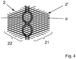
- FIG. 4 is a schematic and again an example based on the semi-finished preliminary stage 1a from Figure 2
- Semifinished product 1 'formed using the method according to the invention is shown in a top view, the continuous reinforcing fibers 5 being guided around later force introduction points 11 of a component to be produced from the semifinished product 1'.
- bolts or the like can be inserted into the force introduction points 11 later on in the component to be produced, the endless reinforcing fibers 5 guided around the force introduction points 11 bringing about a suitable geometry stabilization even with increased force input into the force introduction points 11.
- the continuous reinforcing fibers 5 or the continuous fibers 2, 2', 2 ", 2" ', 2 "" can also be laid in a form other than that shown in the figures.
- the semi-finished product 1 to be produced can also have a different final contour shape and / or be formed from a different number of layers 21, 22, 23, 24, 25.
Description
Die vorliegende Erfindung betrifft ein Verfahren zum Herstellen von flächigen, faserverstärkten Halbzeugen für Faser-Kunststoff-Verbundbauteile, bei dem Endlosfasern in wenigstens zwei Lagen übereinander während eines mittels eines Lagentransportmechanismus durchgeführten kontinuierlichen Transportes dieser Lagen abgelegt werden, wobei die Faserorientierung in einer ersten Lage der wenigstens zwei Lagen sich von der Faserorientierung in wenigstens einer weiteren Lage der wenigstens zwei Lagen während des Transportes der wenigstens zwei Lagen unterscheidet.The present invention relates to a method for producing flat, fiber-reinforced semi-finished products for fiber-plastic composite components, in which continuous fibers are deposited in at least two layers on top of each other during a continuous transport of these layers carried out by means of a layer transport mechanism, the fiber orientation in a first layer of the at least two layers differ from the fiber orientation in at least one further layer of the at least two layers during the transport of the at least two layers.
Insbesondere im Flugzeugbau und im Sportbereich, aber auch im Automobilbau gewinnt der Einsatz von faserverstärkten Kunststoffen zunehmend an Bedeutung. Dies liegt nicht zuletzt an dem vergleichsweise geringen Gewicht sowie der hohen Steifigkeit und Festigkeit dieser Werkstoffe. Faserverstärkte Kunststoffe bestehen aus Verstärkungsfasern und einer Kunststoffmatrix, welche die Fasern umgibt, wobei die mechanischen und thermischen Eigenschaften von faserverstärkten Kunststoffen über eine Vielzahl von Parametern eingestellt werden können. Beispielsweise können die Eigenschaften von faserverstärkten Kunststoffen durch Variation der Faserausrichtung, des Faservolumenanteils, der Schichtreihenfolge und -ausbildung, der Faserlänge, der Eigenschaften der Fasern und/oder des Matrixwerkstoffes beeinflusst werden.The use of fiber-reinforced plastics is becoming increasingly important, particularly in aircraft construction and in the sports sector, but also in automobile construction. This is not least due to the comparatively low weight as well as the high rigidity and strength of these materials. Fiber-reinforced plastics consist of reinforcing fibers and a plastic matrix that surrounds the fibers, whereby the mechanical and thermal properties of fiber-reinforced plastics can be adjusted using a large number of parameters. For example, the properties of fiber-reinforced plastics can be influenced by varying the fiber orientation, the fiber volume fraction, the layer sequence and formation, the fiber length, the properties of the fibers and / or the matrix material.
Aus dem Stand der Technik sind unterschiedliche Verfahren zum Herstellen von faserverstärkten Kunststoffen bekannt. Faserverstärkte Kunststoffe können beispielsweise mittels Spritzgussverfahren, Strangziehverfahren oder als Sheet Molding Compound hergestellt werden. Häufig werden faserverstärkte Kunststoffe jedoch als Laminate ausgebildet, da hierbei die Vorteile einer individuellen Faserausrichtung ausgenutzt werden können. Die hierfür eingesetzten Laminate bestehen in der Regel aus übereinander angeordneten Faserlagen, deren Fasern in unterschiedlichen Faserrichtungen angeordnet sind.Various methods for producing fiber-reinforced plastics are known from the prior art. Fiber-reinforced plastics can be produced, for example, by means of injection molding processes, extrusion processes or as a sheet molding compound. Often, however, fiber-reinforced plastics are designed as laminates, since the advantages of an individual fiber alignment can be used here. The laminates used for this generally consist of fiber layers arranged one above the other, the fibers of which are arranged in different fiber directions.
In der Druckschrift
Nachteilig bei dieser Art der Herstellung von Vorformlingen für faserverstärkte Kunststoffbauteile ist, dass für jede der Lagen der Preform jeweils eine als Trägermaterial dienende Unter- bzw. Zwischenlage benötigt wird, die die Kennwerte des aus der Preform auszubildenden Bauteils verschlechtern.The disadvantage of this type of production of preforms for fiber-reinforced plastic components is that each of the preform layers requires an underlay or intermediate layer serving as a carrier material, which worsens the characteristics of the component to be formed from the preform.
In der Druckschrift
Bei dieser Variante zum Herstellen von faserverstärkten Halbzeugen entsteht verhältnismäßig hoher Materialabfall durch das Ausschneiden der Preforms aus dem Gelege.In this variant for the production of fiber-reinforced semi-finished products, a relatively high amount of material waste arises from the cutting of the preforms from the scrim.
Aus der Druckschrift
Es ist daher die Aufgabe der vorliegenden Erfindung, ein kostengünstiges Verfahren zum Herstellen von flächigen, faserverstärkten Halbzeugen für Faser-Kunststoff-Verbundbauteile mit vorteilhaften Bauteilfestigkeitskennwerten bereitzustellen, welches es ermöglicht, faserverstärkte Halbzeuge in Endkonturform effizient und mit möglichst geringem Materialabfall herzustellen.It is therefore the object of the present invention to provide a cost-effective method for producing flat, fiber-reinforced semi-finished products for fiber-plastic composite components with advantageous component strength parameters, which makes it possible to produce fiber-reinforced semi-finished products in final shape efficiently and with the least possible waste of material.
Die Aufgabe wird durch ein Verfahren nach Anspruch 1 gelöst, wobei die Endlosfasern der wenigstens zwei Lagen ohne seitliche Halterung der Endlosfasern in einer von der Breite eines verwendeten Transportbandes und/oder der Breite des Lagentransportmechanismus unabhängigen, aber sich nicht über die Breite des Transportbandes und/oder die Breite des Lagentransportmechanismus erstreckenden Halbzeugendkonturform gerade abgelegt und entsprechend der jeweiligen Breite der Halbzeugendkonturform nach dem Ablegen abgelängt werden und in wenigstens einem Bereich der Halbzeugendkonturform auf den Lagen wenigstens eine eine Verstärkung ausbildende Endlos-Verstärkungsfaser verlegt wird.The object is achieved by a method according to
Erfindungsgemäß werden zur Ausbildung eines flächigen, faserverstärkten Halbzeuges in einer ersten Verlegeeinrichtung Endlosfasern in Halbzeugendkonturform eine erste Lage ausbildend auf ein Trägermaterial oder ein Transportband abgelegt und entsprechend der jeweiligen Breite der Halbzeugendkonturform abgelängt. Hierbei sind die Endlosfasern der ersten Lage gerade verlegt und weisen eine erste Faserorientierung auf. Erfindungsgemäß werden die Endlosfasern also erst abgelängt, wie beispielsweise abgeschnitten, wenn die jeweilige Endlosfaser wenigstens teilweise auf das Trägermaterial oder das Transportband abgelegt wurde. Vorzugsweise wird die Endlosfaser dabei schon dann abgelängt, wenn sie zwar schon, aber noch nicht vollständig auf dem Trägermaterial oder dem Transportband aufliegt. Nach dem Ablängen fällt dann das bis dahin noch nicht auf dem Trägermaterial oder dem Transportband aufliegende Ende der abgelängten Endlosfaser auf das Trägermaterial oder das Transportband. Das Ablängen erfolgt also erfindungsgemäß beim Verlegen der Endlosfasern auf dem Trägermaterial oder dem Transportband. Das Ablegen und Ablängen erfolgt während des vorzugsweise kontinuierlichen Transportes bzw. Weitertransportes der bereits abgelegten Endlosfasern. Die Halbzeugendkonturform wird demnach bei der vorliegenden Erfindung durch eine Vielzahl von aus den Endlosfasern durch Ablängen erhaltenen Einzelrovings ausgebildet, wobei die Einzelrovings endkonturnah beim Ablegen auf dem Trägermaterial oder dem Transportband abgelängt werden.According to the invention, to form a flat, fiber-reinforced semifinished product in a first laying device, continuous fibers in semifinished end contour form are placed on a carrier material or a conveyor belt to form a first layer and cut to length according to the respective width of the semifinished end contour form. Here, the continuous fibers of the first layer are laid straight and have a first fiber orientation. According to the invention, the continuous fibers are therefore only cut to length, for example cut off, when the respective continuous fiber has been at least partially deposited on the carrier material or the conveyor belt. The continuous fiber is preferably cut to length when it is already on the carrier material, but not yet completely or on the conveyor belt. After the cutting to length, the end of the cut-to-length continuous fiber not yet resting on the carrier material or the conveyor belt then falls onto the carrier material or the conveyor belt. According to the invention, cutting to length takes place when the continuous fibers are laid on the carrier material or the conveyor belt. The filing and cutting to length take place during the preferably continuous transport or further transport of the endless fibers that have already been deposited. The semifinished end contour shape is accordingly formed in the present invention by a multiplicity of individual rovings obtained from the continuous fibers by cutting to length, the individual rovings being cut to near final contour when they are placed on the carrier material or the conveyor belt.
In der aus einer Anzahl von Endlosfasern ausgebildeten ersten Lage sind die einzelnen Endlosfasern gleichmäßig über die komplette Halbzeugendkonturform verteilt verlegt, wobei alle Endlosfasern dieser Lage jeweils die gleiche Faserorientierung aufweisen.In the first layer formed from a number of continuous fibers, the individual continuous fibers are laid evenly distributed over the complete semi-finished end contour shape, with all continuous fibers of this layer each having the same fiber orientation.
Während die erste Lage durch das Verlegen der wenigstens einen Endlosfaser ausgebildet wird, wird das die wenigstens eine Lage transportierende Transportband weiterbewegt und/oder der Lagentransportmechanismus kontinuierlich weiter betrieben, wodurch die Fertigungszeit für die Herstellung des faserverstärkten Halbzeuges möglichst gering gehalten werden kann.While the first layer is formed by laying the at least one continuous fiber, the conveyor belt transporting the at least one layer is moved further and / or the layer transport mechanism continues to operate, whereby the production time for the production of the fiber-reinforced semi-finished product can be kept as short as possible.
In einer sich in Förderrichtung der ersten Lage an die erste Verlegeeinrichtung anschließenden zweiten Verlegeeinrichtung werden direkt auf die erste Lage wenigstens eine weitere Lage ausbildende Endlosfasern aufgebracht, wobei auch hierbei das Förderband bzw. der Lagentransportmechanismus kontinuierlich weiterbetrieben wird.In a second laying device adjoining the first laying device in the conveying direction of the first layer, at least one further layer of continuous fibers are applied directly to the first layer, the conveyor belt or the layer transport mechanism also continuing to operate here.
Bei dem erfindungsgemäßen Verfahren werden auch die die wenigstens eine weitere Lage ausbildenden Endlosfasern in der Endkonturform des Halbzeuges verlegt, wobei die Endlosfasern der weiteren Lage eine sich von der Faserorientierung der Endlosfasern der ersten Lage unterscheidende Faserorientierung aufweisen. Durch die unterschiedlichen Faserorientierungen der aufeinander abgelegten Lagen kann insbesondere die Festigkeit und Stabilität des hergestellten Halbzeuges gesteigert werden.In the method according to the invention, the continuous fibers forming the at least one further layer are also laid in the final contour shape of the semi-finished product, the continuous fibers of the further layer having a fiber orientation different from the fiber orientation of the continuous fibers of the first layer. The different fiber orientations of the layers placed on top of one another can in particular increase the strength and stability of the semi-finished product produced.
Die die weitere Lage ausbildenden Endlosfasern sind bevorzugt gleichmäßig über die Halbzeugendkonturform verteilt mit gleicher Faserorientierung verlegt.The continuous fibers forming the further layer are preferably laid evenly distributed over the semifinished end contour shape with the same fiber orientation.
Die Endlosfasern der einzelnen Lagen sind jeweils geradlinig verlegt, da hierdurch das erfindungsgemäße Verfahren mit hoher Effizienz realisiert werden kann.The continuous fibers of the individual layers are each laid in a straight line, since this allows the method according to the invention to be implemented with high efficiency.
Je nach Anwendungsfall des hergestellten Halbzeuges kann die Anzahl der übereinander angeordneten Lagen variieren. Insofern mehr als zwei Lagen abgelegt werden, schließen sich in Lagentransportrichtung zusätzliche Verlegeeinrichtungen zum Ablegen weiterer Lagen an die ersten beiden Verlegeeinrichtungen an. Vorteilhafterweise sollte die Anzahl der Lagen des Halbzeuges anwendungsfallspezifisch gewählt werden.Depending on the application of the semi-finished product produced, the number of layers arranged one above the other can vary. If more than two layers are laid down, additional laying devices for laying down further layers follow the first two laying devices in the direction of layer transport. The number of layers of the semifinished product should advantageously be selected specifically for the application.
Zum optimalen Verlegen der Endlosfasern hat es sich als vorteilhaft erwiesen, wenn jene Verlegeeinrichtungen, die keine parallel zu der Transportrichtung ausgerichtete Endlosfasern verlegen, entlang des Transportbandes oder Transportmechanismuses verfahrbar angeordnet sind, da so die Endlosfasern kontinuierlich über die Halbzeugendkonturform verteilt werden können. In anderen Ausführungsformen des erfindungsgemäßen Verfahrens können jedoch auch alle Verlegeeinrichtungen, keine der Verlegeeinrichtungen oder andere als die zuvor erwähnten Verlegeeinrichtungen verfahrbar vorgesehen werden.For optimal laying of the continuous fibers, it has proven to be advantageous if those laying devices that do not lay continuous fibers aligned parallel to the transport direction are arranged to be movable along the conveyor belt or transport mechanism, since the continuous fibers can thus be continuously distributed over the final shape of the semi-finished product. In other embodiments of the method according to the invention, however, all the laying devices, none of the laying devices or laying devices other than those mentioned above can be provided so as to be movable.
Vorteilhafterweise unterscheiden sich die Faserorientierungsrichtungen der Endlosfasern der ersten bis n-ten Lage voneinander. In weiteren Ausgestaltungsvarianten kann wenigstens eine der Lagen drei bis n jedoch auch eine der Endlos-Verstärkungsfaserorientierungsrichtung der ersten oder zweiten Lage und/oder einer der darauf abgelegten Lagen entsprechende Faserorientierungsrichtung aufweisen.Advantageously, the fiber orientation directions of the continuous fibers of the first to nth layers differ from one another. In further design variants, at least one of the layers three to n can, however, also have a fiber orientation direction corresponding to the endless reinforcing fiber orientation direction of the first or second layer and / or one of the layers deposited thereon.
Das erfindungsgemäße Verfahren arbeitet halbzeugendkonturentsprechend, kontinuierlich, ist großserientauglich und hochproduktiv.The method according to the invention works in accordance with the semifinished contour, continuously, is suitable for large-scale production and is highly productive.
In speziellen Ausführungsformen des Halbzeuges kann zudem zwischen den einzelnen Lagen ausbildenden Endlosfasern wenigstens eine zusätzliche, stabilisierende und/oder funktionserfüllende Zwischenschicht eingebracht werden.In special embodiments of the semi-finished product, at least one additional, stabilizing and / or function-fulfilling intermediate layer can also be introduced between the individual layers of continuous fibers.
Erfindungsgemäß werden die Endlosfasern der einzelnen Lagen in Halbzeugendkonturform, unabhängig von der Breite des verwendeten Transportbandes und/oder Lagentransportmechanismus, aber nicht über die Breite des Transportbandes und/oder Lagentransportmechanismus hinausgehend abgelegt, wodurch ein kostengünstiges faserverstärktes Halbzeug ohne bzw. mit einem sehr geringen Anteil an Materialabfall hergestellt werden kann.According to the invention, the continuous fibers of the individual layers are deposited in semifinished end contour form, regardless of the width of the conveyor belt and / or layer transport mechanism used, but not beyond the width of the conveyor belt and / or layer transport mechanism, thereby creating an inexpensive fiber-reinforced Semi-finished products can be produced without or with a very small proportion of material waste.
Durch das Ablegen der Endlosfasern in Halbzeugendkonturform kann insbesondere dann, wenn kein zusätzliches Trägermaterial zum Ausbilden des Halbzeuges verwendet wird, auf ein Zuschneiden der durch das Ablegen der Endlosfasern ausgebildeten Lagen verzichtet werden, womit der Bearbeitungsprozess verkürzt und die Fertigungs- und Materialkosten gesenkt werden können. Zur Herstellung von Halbzeugen mit sehr hohen Maßanforderungen und/oder einer sehr komplexen Geometrie, welche sich beispielsweise nur sehr schwierig durch Verlegen der Endlos-Verstärkungsfasern erzeugen lassen, können die abgelegten Lagen jedoch auch zusätzlich zugeschnitten und/oder ausgestanzt werden. Hierbei kann entweder die komplette Halbzeugendkonturform oder nur ein Teil der Halbzeugendkonturform zugeschnitten und/oder ausgestanzt werden.By depositing the continuous fibers in the final shape of the semi-finished product, especially when no additional carrier material is used to form the semi-finished product, it is possible to dispense with cutting the layers formed by depositing the continuous fibers, thereby shortening the machining process and lowering the manufacturing and material costs. For the production of semi-finished products with very high dimensional requirements and / or a very complex geometry, which, for example, can only be produced with great difficulty by laying the continuous reinforcing fibers, the deposited layers can also be cut and / or punched out. Either the complete semifinished end contour shape or only a part of the semifinished end contour shape can be cut to size and / or punched out.
Bei dem erfindungsgemäßen Verfahren werden die Endlosfasern nach dem Ablegen zu einer der Lagen während des Transportes der jeweiligen Lage abgelängt. Durch das Ablängen der Endlosfasern während des Transportes der wenigstens einen Lage wird die Fertigungszeit für die Herstellung des faserverstärkten Halbzeuges wesentlich verkürzt. Zudem wird durch den somit kontinuierlich ermöglichten Lagentransport den Steuerungsaufwand der verwendeten Halbzeugproduktionsanlage verringert.In the method according to the invention, after being deposited into one of the layers, the continuous fibers are cut to length during the transport of the respective layer. By cutting the continuous fibers to length during the transport of the at least one layer, the production time for the production of the fiber-reinforced semifinished product is significantly shortened. In addition, the continuously enabled layer transport reduces the control effort of the semi-finished product production system used.
Das Ablängen der Endlosfasern kann beispielsweise mittels Laser, Ultraschall, Wasserstrahl oder mechanischem Schneiden erfolgen. Ferner kann die wenigstens eine Endlos-Verstärkungsfaser bzw. Endlosfaser auch gerissen oder in anderer Form durchtrennt, wie zum Beispiel abgerissen, werden.The continuous fibers can be cut to length, for example, by means of a laser, ultrasound, water jet or mechanical cutting. Furthermore, the at least one continuous reinforcing fiber or continuous fiber can also be torn or severed in another form, such as torn off.
Das bloße Ablegen der Endlosfasern und der Verzicht auf eine seitliche Halterung der Endlosfasern führt dazu, dass das erfindungsgemäße Verfahren einfach und schnell ausgeführt werden kann, da die verlegten Endlosfasern nicht erst umständlich und bearbeitungszeitbeanspruchend in eine Halterung oder ähnliches eingehängt, eingelegt oder eingeklemmt werden müssen. Insbesondere kann ein Halten der Endlosfasern durch eine an dem Transportband oder dem Lagentransportmechanismus vorgesehene Haltevorrichtung, wie beispielsweise eine an oder nahe einem Randbereich des Transportbandes oder des Lagentransportmechanismus angebrachte Kammleiste, um welche die zu verlegenden Endlosfasern geschlungen werden, vermieden werden.The mere laying down of the continuous fibers and the waiver of a lateral mounting of the continuous fibers means that the method according to the invention can be carried out quickly and easily, since the laid continuous fibers do not have to be hung, inserted or clamped into a mounting or the like, which is laborious and time-consuming. In particular, holding the continuous fibers by a holding device provided on the conveyor belt or the layer transport mechanism, such as a comb bar attached to or near an edge region of the conveyor belt or the layer transport mechanism, around which the continuous fibers to be laid are looped, can be avoided.
Erfindungsgemäß wird in wenigstens einem Bereich der Halbzeugendkonturform auf den Lagen wenigstens eine eine Verstärkung ausbildende Endlos-Verstärkungsfaser verlegt.According to the invention, at least one continuous reinforcing fiber forming a reinforcement is laid on the layers in at least one area of the semifinished end contour shape.
Durch das Ablegen der wenigstens einen Endlos-Verstärkungsfaser auf die zuvor ausgebildeten wenigstens zwei Lagen des Halbzeuges kann das Halbzeug belastungsspezifisch verstärkt werden und somit höheren Belastungen standhalten. Die Form und Abmessung der aus der wenigstens einen Endlos-Verstärkungsfaser ausgebildeten Verstärkung sowie deren Anordnung auf der Halbzeugendkonturform sind anwendungsfallspezifisch zu wählen. Ferner kann auch die Anzahl der auf die Halbzeugendkonturform aufgebrachten Verstärkungen einsatzspezifisch variieren.By placing the at least one continuous reinforcing fiber on the previously formed at least two layers of the semifinished product, the semifinished product can be reinforced in a load-specific manner and thus withstand higher loads. The shape and dimensions of the reinforcement formed from the at least one continuous reinforcing fiber and its arrangement on the semifinished end contour shape are to be selected specifically for the application. Furthermore, the number of reinforcements applied to the semifinished end contour shape can also vary according to the application.
Je nach Ausgestaltung des herzustellenden Halbzeuges muss die Verstärkung aus Endlos-Verstärkungsfasern nicht zwingend auf den abgelegten Lagen aufgebracht werden, sondern kann auch zwischen zwei Lagen des Halbzeuges eingebracht werden.Depending on the design of the semifinished product to be produced, the reinforcement made of continuous reinforcing fibers does not necessarily have to be applied to the deposited layers, but can also be introduced between two layers of the semifinished product.
Es ist jedoch von Vorteil, die Verstärkung zuoberst auf allen Lagen eines aus den Endlosfasern ausgebildeten Lagenstapels vorzusehen, da es durch den lastpfadgerechten Aufbau der Verstärkung an der Stelle der Verstärkung zu einer Verdickung kommt, wodurch bei einer darauf erfolgenden Ablage weiterer Lagen die Endlosfasern solcher Lagen beispielsweise in ihrer Lage verrutschen können.However, it is advantageous to provide the reinforcement on top of all layers of a stack of layers formed from the continuous fibers, because the load-path-appropriate structure of the reinforcement results in a thickening at the point of the reinforcement, which means that the continuous fibers of such layers are deposited on top of it for example, can slip in their position.
Auch ist es günstig, die Verstärkung in wenigstens einem Randbereich der Halbzeugendkonturform und nicht etwa in deren Mitte vorzusehen.It is also advantageous to provide the reinforcement in at least one edge area of the semifinished end contour shape and not approximately in its center.
Wenigstens eine Endlos-Verstärkungsfaser der Verstärkung einer vorgegebenen Verstärkungskontur kann beispielsweise mäanderförmig und/oder wellenförmig und/oder zickzackförmig und/oder wirr entsprechend einer vorgegebenen Verstärkungskontur verlegt werden.At least one continuous reinforcing fiber of the reinforcement of a predetermined reinforcement contour can be laid, for example, in a meandering and / or undulating and / or zigzag and / or tangled manner according to a predetermined reinforcing contour.
Der Abstand zwischen benachbarten Abschnitten von Endlos-Verstärkungsfasern der Verstärkung kann dabei über die Länge der benachbart angeordneten Abschnitte variieren. Somit ist es beispielsweise möglich, die Endlos-Verstärkungsfasern um bestimmte Krafteinleitungspunkte des späteren Bauteils herumzuleiten.The distance between adjacent sections of continuous reinforcing fibers of the reinforcement can vary over the length of the adjacent sections. It is thus possible, for example, to guide the continuous reinforcing fibers around certain force introduction points of the later component.
Insbesondere im Hinblick auf eine optimale Stabilisierung des herzustellenden Halbzeuges und/oder eine anschließende Verformung der das Halbzeug ausbildenden Lagen hat es sich als vorteilhaft erwiesen, wenn die wenigstens eine, die Verstärkung ausbildende Endlos-Verstärkungsfaser einer vorgegebenen Kontur angepasst verlegt wird. Hierbei kann/können die Endlos-Verstärkungsfaser(n), wie bereits oben erwähnt, mit variierendem Abstand zueinander verlegt werden, wodurch in das Halbzeug beispielsweise durch Verformung erzeugte Knicke, Einengungen oder ähnliches besonders gut ausgebildet werden können. Zudem kann in Bereichen höherer Belastung der Abstand der die Verstärkung ausbildenden Endlos-Verstärkungsfaser(n) zueinander verringert werden und in Bereichen geringerer Belastung ein vergleichsweise großer Abstand gewählt werden, sodass eine sich verjüngende Stelle in der Verstärkung ausgebildet wird. Resultierend aus einer derartigen Anordnung der Endlos-Verstärkungsfaser(n) können der Einsatz an Endlos-Verstärkungsfasern reduziert und damit die Kosten und das Gewicht des herzustellenden Halbzeuges minimiert werden.In particular with regard to an optimal stabilization of the semi-finished product to be produced and / or a subsequent deformation of the layers forming the semi-finished product, it has proven to be advantageous if the at least one continuous reinforcement fiber forming the reinforcement is laid in a manner adapted to a predetermined contour. Here, the continuous reinforcing fiber (s), as already mentioned above, can be laid with varying spacing from one another, so that kinks, constrictions or the like generated in the semifinished product, for example, can be formed particularly well. In addition, in areas of higher loading, the distance between the continuous reinforcing fiber (s) forming the reinforcement can be reduced and in areas of lower loading a comparatively large distance can be selected so that a tapering point is formed in the reinforcement. As a result of such an arrangement of the continuous reinforcing fiber (s), the use of continuous reinforcing fibers can be reduced and thus the costs and the weight of the semi-finished product to be produced can be minimized.
Damit das herzustellende Halbzeug besonders hohen Belastungen standhalten kann, hat es sich zudem als vorteilhaft erwiesen, wenn die wenigstens eine Endlos-Verstärkungsfaser der Verstärkung lastpfadgerecht verlegt wird. In Abhängigkeit von dem Einsatzgebiet und/oder der maximalen auftretenden Belastung können auch mehrere die Verstärkung ausbildende Endlos-Verstärkungsfasern übereinander gelegt werden.In order that the semi-finished product to be manufactured can withstand particularly high loads, it has also proven to be advantageous if the at least one continuous reinforcing fiber of the reinforcement is laid in accordance with the load path. Depending on the area of use and / or the maximum load that occurs, several continuous reinforcing fibers forming the reinforcement can also be laid one on top of the other.
In einer besonders bevorzugten Ausführungsform des erfindungsgemäßen Verfahrens zum Herstellen eines faserverstärkten Halbzeuges werden die wenigstens zwei Lagen direkt auf eine Oberfläche des Transportbandes, ohne Verwendung eines Trägermaterials unter oder zwischen diesen Lagen abgelegt.In a particularly preferred embodiment of the method according to the invention for producing a fiber-reinforced semifinished product, the at least two layers are deposited directly on a surface of the conveyor belt without using a carrier material under or between these layers.
Durch den Verzicht auf ein Trägermaterial können unter anderem die Material- und Fertigungskosten gering gehalten werden, da beispielsweise die Kosten für das Trägermaterial und die Kosten für das Handling dieses entfallen. Zudem wird auch das Herstellungsverfahren an sich vereinfacht, da unter anderem das Zuführen des Trägermaterials und das Verbinden des Trägermaterials mit den Endlosfasern wegfallen. Vorteilhafterweise weisen lediglich aus Endlosfasern ohne zusätzliches Trägermaterial hergestellte Halbzeuge auch ein geringeres Gewicht auf, was insbesondere für Leichtbauanwendungen vorteilhaft nutzbar ist.By dispensing with a carrier material, among other things, the material and production costs can be kept low, since, for example, the costs for the carrier material and the costs for handling it are eliminated. In addition, the manufacturing process per se is also simplified since, among other things, the feeding of the carrier material and the connection of the carrier material to the continuous fibers are omitted. Advantageously, semi-finished products made only from continuous fibers without additional carrier material also have a lower weight, which can be used advantageously in particular for lightweight construction applications.
In alternativen Ausführungsformen des erfindungsgemäßen Verfahrens kann zur Herstellung des Halbzeuges auch ein zusätzliches Trägermaterial unter und/oder zwischen und/oder über den wenigstens zwei Lagen verwendet werden. Anwendungsfallspezifisch kann dieses Trägermaterial also als Grund- und/oder Zwischen- und/oder Deckschicht den aus den Endlosfasern ausgebildeten Lagen zugeführt werden. Durch den Einsatz wenigstens eines zusätzlichen Trägermaterials kann die Stabilität des herzustellenden Halbzeuges erhöht werden. Das Trägermaterial kann dem Herstellungsprozess entweder als Materialbahn zugeführt werden und zu einem späteren Zeitpunkt zugeschnitten werden oder bereits zugeschnitten den Herstellungsprozess zugeführt werden. Hierbei weist das Trägermaterial vorzugsweise die Halbzeugendkonturform auf, kann jedoch auch jede beliebige andere Form aufweisen und die aus den wenigstens zwei Lagen mit der Verstärkung ausgebildete Halbzeugendkonturform somit komplett oder nur teilweise bedecken.In alternative embodiments of the method according to the invention, an additional carrier material can also be used under and / or between and / or over the at least two layers to produce the semifinished product. Depending on the application, this carrier material can thus be supplied as a base and / or intermediate and / or cover layer to the layers formed from the continuous fibers. By using at least one additional carrier material, the stability of the semi-finished product to be produced can be increased. The carrier material can either be fed to the manufacturing process as a material web and cut to size at a later point in time or fed to the manufacturing process already cut. In this case, the carrier material preferably has the semifinished end contour shape, but can also have any other shape and thus completely or only partially cover the semifinished end contour shape formed from the at least two layers with the reinforcement.
In einer bevorzugten Ausführungsform des erfindungsgemäßen Verfahrens werden die Endlosfasern wenigstens einer der wenigstens zwei Lagen in einem Abstand zueinander in der jeweiligen Lage verlegt, der von 6 mm bis 100 mm beträgt. Dabei ist der Abstand der Endlosfasern innerhalb der jeweiligen Lage vorzugsweise gleich groß.In a preferred embodiment of the method according to the invention, the continuous fibers of at least one of the at least two layers are laid at a distance from one another in the respective layer which is from 6 mm to 100 mm. The distance between the continuous fibers within the respective layer is preferably the same.
Durch die Anordnungen der Endlosfasern mit gleichmäßigem Abstand zueinander können Halbzeuge mit über die gesamte Halbzeugfläche konstantem Belastungswiderstand hergestellt werden. Vorteilhafterweise sollte der Abstand zwischen den Endlosfasern bzw. Teilen von Endlosfasern zueinander in Abhängigkeit der Bauteilgeometrie gewählt werden.By arranging the continuous fibers at a uniform distance from one another, semi-finished products can be produced with a constant load resistance over the entire semi-finished product surface. The distance between the continuous fibers or parts of continuous fibers to one another should advantageously be selected as a function of the component geometry.
In alternativen Ausführungsformen des erfindungsgemäßen Verfahrens können die Endlosfasern auch mit einem Abstand von kleiner als 6 mm oder größer als 100 mm zueinander verlegt werden. Ebenso können die Endlosfasern innerhalb einer Lage in alternativen Ausführungsformen der vorliegenden Erfindung auch mit unterschiedlich großen, der partiellen Belastung des Halbzeuges angepassten Abständen zueinander verlegt werden.In alternative embodiments of the method according to the invention, the continuous fibers can also be laid with a spacing of less than 6 mm or greater than 100 mm from one another. Likewise, in alternative embodiments of the present invention, the continuous fibers within a layer can also be laid with differently large distances from one another that are adapted to the partial load on the semi-finished product.
In zweckmäßigen Ausgestaltungen des erfindungsgemäßen Verfahrens werden trockene Filamente oder Faserverbände, aus Verstärkungs- und Matrixfasern ausgebildete Hybridfasern, bebinderte Filamente oder Faserverbände, während des Halbzeugherstellungsverfahrens zu bebindernde Filamente oder Faserverbände und/oder thermoplastische unidirektionale Bänder als Endlosfasern und/oder Endlos-Verstärkungsfaser verwendet.In expedient embodiments of the method according to the invention, dry filaments or fiber assemblies, hybrid fibers formed from reinforcing and matrix fibers, bound filaments or fiber assemblies are used during the semi-finished product manufacturing process Filaments or fiber assemblies to be bound and / or thermoplastic unidirectional tapes are used as continuous fibers and / or continuous reinforcing fibers.
Vorteilhafterweise können durch das Bebindern wenigstens einzelner Filamente, Fasern und/oder Faserverbände einzelne Filamente, Fasern und/oder Faserverbände zusammengefügt bzw. gegen verrutschen gesichert werden. Zum Bebindern werden beispielsweise thermoplastische Polymere eingesetzt, welche flächig auf die Filamente, Fasern und/oder Faserbündel aufgesprüht, aufgestreut oder flächig aufgebracht werden. Durch Erwärmung werden die Binder klebrig, wodurch eine Fixierung erreicht wird.Advantageously, by binding at least individual filaments, fibers and / or fiber assemblies, individual filaments, fibers and / or fiber assemblies can be joined together or secured against slipping. For binding, for example, thermoplastic polymers are used which are sprayed, scattered or applied flat onto the filaments, fibers and / or fiber bundles. When heated, the binders become sticky, which results in a fixation.
Insbesondere können für die Ausbildung der Endlosfasern und/oder Endlosverstärkungsfaser(n) Filamente und/oder Fasern aus Carbon, Bor, Glas, Keramik, Basalt und/oder Aramid zum Einsatz kommen, welche trocken, als aus Verstärkungs- und Matrixfasern ausgebildete Hybridfasern, bebindert oder während des Herstellungsverfahrens zu bebindernd eingesetzt werden können.In particular, filaments and / or fibers made of carbon, boron, glass, ceramic, basalt and / or aramid can be used for the formation of the continuous fibers and / or continuous reinforcing fiber (s), which bind dry as hybrid fibers made of reinforcing and matrix fibers or can be used to bind during the manufacturing process.
Ferner können in alternativen Ausführungsformen des erfindungsgemäßen Verfahrens auch andere Fasern, Faserbündel oder Filamente zur Ausbildung der Endlosfasern und/oder Endlosverstärkungsfaser(n) eingesetzt werden, welche nicht zwingend bebindert sein müssen. Derartige Fasern, Filamente oder Faserbündel können beispielsweise auch mittels eines anderen Beschichtungsverfahrens beschichtet sein bzw. werden.Furthermore, in alternative embodiments of the method according to the invention, other fibers, fiber bundles or filaments can also be used to form the continuous fibers and / or continuous reinforcing fiber (s) which do not necessarily have to be bound. Such fibers, filaments or fiber bundles can, for example, also be coated by means of another coating process.
Alternativ oder zusätzlich zu den einzelnen Filamenten, Fasern und/oder Faserbündeln können bei der Herstellung eines faserverstärkten Halbzeuges auch sogenannte unidirektionale Bänder zum Einsatz kommen. Unter unidirektionalen Bändern sind insbesondere dicht aneinandergereihte, beispielsweise durch ein Harz in Position gehaltene Stränge zu verstehen. Ferner können die einzelnen nebeneinander angeordneten Stränge auch durch Schussfäden, welche quer in die nebeneinander angeordneten Stränge eingeschossen werden, zusammengehalten werden.As an alternative or in addition to the individual filaments, fibers and / or fiber bundles, so-called unidirectional tapes can also be used in the production of a fiber-reinforced semi-finished product. Unidirectional tapes are to be understood as meaning, in particular, strands that are closely lined up, for example, held in position by a resin. Furthermore, the individual strands arranged next to one another can also be held together by weft threads which are shot transversely into the strands arranged next to one another.
Anwendungsfallspezifisch können innerhalb einer Lage gleiche oder unterschiedliche Fasern, Faserbündel, Filamente und/oder unidirektionale Bänder mit gleichen oder unterschiedlichen Eigenschaften Anwendung finden. Ebenso können sich auch die Fasern, Faserbündel, Filamente und/oder unidirektionale Bänder der einzelnen Lagen voneinander unterscheiden oder gleich sein.Depending on the application, the same or different fibers, fiber bundles, filaments and / or unidirectional tapes with the same or different properties can be used within a layer. Likewise, the fibers, Fiber bundles, filaments and / or unidirectional tapes of the individual layers differ from one another or be the same.
Die Endlosfasern jeder der wenigstens zwei Lagen sind also bei dem erfindungsgemäßen Verfahren jeweils unidirektional ausgerichtet. Aber die Endlosfaser-Verstärkungsfasern der Verstärkung sind lastpfadgerecht ausgelegt, können also beispielsweise wellenförmig, zickzackförmig oder in anderer, zweckmäßiger Ausgestaltung abgelegt sein. Das erfindungsgemäße Verfahren kombiniert also da halbzeugendkonturentsprechende Ablegen der Endlosfasern in den wenigstens zwei Lagen mit der lastpfadgerechten Ablage der wenigstens eine Endlos-Verstärkungsfaser der Verstärkung.The continuous fibers of each of the at least two layers are therefore each unidirectional in the method according to the invention. However, the continuous fiber reinforcement fibers of the reinforcement are designed in accordance with the load path, that is to say, for example, they can be stored in an undulating, zigzag or other, expedient configuration. The method according to the invention therefore combines the storage of the continuous fibers in the at least two layers in accordance with the semi-finished contour with the storage of the at least one continuous reinforcing fiber of the reinforcement in accordance with the load path.
In alternativen Ausführungsführungsvarianten des erfindungsgemäßen Verfahrens kann der Lagentransport zum Ablegen und/oder Ablängen der Endlosfasern und/oder der wenigstens einer Endlos-Verstärkungsfaser auch getaktet durchgeführt werden.In alternative implementation variants of the method according to the invention, the layer transport for depositing and / or cutting the continuous fibers and / or the at least one continuous reinforcing fiber can also be carried out in a clocked manner.
Vorzugsweise sind die in den wenigstens zwei Lagen jeweils nebeneinander liegenden Endlosfasern aus aufgespreizten Einzelrovings ausgebildet und weisen eine Flächenmasse in der jeweiligen Lage in einem Bereich von 50 bis 300 g/m2 auf. In den unterschiedlichen Lagen des Halbzeuges sind verschiedene Flächengewichte möglich. Das jeweilige Flächengewicht der Lage wird durch das verwendete Endlosfaservorprodukt, also durch die jeweils verwendete Endlosfaserspule, bestimmt.The continuous fibers lying next to one another in the at least two layers are preferably formed from spread individual rovings and have a weight per unit area in the respective layer in a range from 50 to 300 g / m 2 . Different grammages are possible in the different layers of the semi-finished product. The respective weight per unit area of the layer is determined by the continuous fiber pre-product used, that is to say by the respective continuous fiber bobbin used.
Beispielsweise kann in dem erfindungsgemäßen Verfahren zur Ausbildung der für die Herstellung der wenigstens zwei Lagen verwendeten Endlosfasern ein 50K-Roving, also ein aus 50000 Einzelfilamenten bestehender Faserstrang, mit einer Breite von ca. 14 bis 15 mm und einem Flächengewicht von ca. 300 g/m2 eingesetzt werden, der durch einen dem erfindungsgemäßen Verfahren vorgelagerten Aufspreizprozess in Einzelrovings aufgespreizt wird, die beispielsweis ein Flächengewicht von 150 g/m2 besitzen und die dann als Endlosfasern zur Ausbildung der wenigstens zwei Lagen verwendet werden. Grundsätzlich sind auch andere Rovings, wie beispielsweise 24K-Rovings, einsetzbar.For example, in the method according to the invention for forming the continuous fibers used to produce the at least two layers, a 50K roving, i.e. a fiber strand consisting of 50,000 individual filaments, with a width of approx. 14 to 15 mm and a weight per unit area of approx. 300 g / m 2 are used, which is spread out into individual rovings by a spreading process upstream of the method according to the invention, which for example have a basis weight of 150 g / m 2 and which are then used as continuous fibers to form the at least two layers. In principle, other rovings, such as 24K rovings, can also be used.
Nach Ablage von wenigstens zwei der Lagen des Halbzeuges können die in Halbzeugendkonturform abgelegten Lagen, vorteilhafterweise einschließlich der Verstärkung, thermisch, mechanisch und/oder chemisch verfestigt und damit in ihrer Form fixiert. Vorzugsweise erfolgt die thermische, mechanische und/oder chemische Verfestigung dann, wenn alle der Lagen abgelegt sind. Es kann jedoch in bestimmten Ausführungsformen der Erfindung auch eine Zwischenverfestigung einzelner Lagenanordnungen erfolgen. So kann beispielsweise die Verfestigung und/oder Fixierung der Lagen nicht erst am Ende des Lagenablageprozesses stattfinden, sondern kann beispielsweise auch nach dem Ablegen jeder einzelnen Lage des Halbzeuges, jeder zweiten, jeder n-ten oder nach einer variierenden, unregelmäßigen Anzahl an abgelegten Lagen durchgeführt werden.After at least two of the layers of the semifinished product have been deposited, the layers deposited in the semifinished end contour shape, advantageously including the reinforcement, can be thermally, mechanically and / or chemically solidified and thus fixed in their shape. The thermal, mechanical and / or chemical consolidation preferably takes place when all of the layers have been discarded. However, in certain embodiments of the invention, an intermediate consolidation of individual layer arrangements can also take place. For example, the consolidation and / or fixing of the layers cannot take place at the end of the layer deposition process, but can also be carried out after each individual layer of the semi-finished product has been deposited, every second, every nth or after a varying, irregular number of deposited layers will.
Eine Verfestigung und/oder Fixierung der Lagen kann beispielweise durch Druck und/oder Temperatureintrag in Form von Infrarotbestrahlung, Ultraschallbeaufschlagung, Heißluftbeaufschlagung, Laserbehandlung oder ähnlichem erfolgen.The layers can be solidified and / or fixed, for example, by applying pressure and / or applying temperature in the form of infrared radiation, ultrasound, hot air, laser treatment or the like.
Die chemische, thermische und/oder mechanische Verfestigung und/oder Fixierung wenigstens einer der Lagen kann erfindungsgemäß örtlich begrenzt, beispielsweise nur an den Seitenrändern der Halbzeugendkonturform, punktuell oder über die ganze Fläche der Halbzeugendkonturform vorgenommen werden.The chemical, thermal and / or mechanical consolidation and / or fixation of at least one of the layers can according to the invention be locally limited, for example only on the side edges of the semifinished end contour shape, selectively or over the entire area of the semifinished end contour shape.
Vorzugsweise weisen die wenigstens zwei Lagen des mit dem erfindungsgemäßen Verfahren hergestellten Halbzeuges eine symmetrische Anordnung der verwendeten Endlosfasern, also eine Spiegelsymmetrie der Lagen in der Dickenrichtung eines aus den wenigstens zwei Lagen ausgebildeten Lagenstapels, auf. Dies kann in speziellen Ausführungsformen des erfindungsgemäßen Verfahrens auch dadurch realisiert werden, dass zunächst ein in seinen Lagen unsymmetrischer Lagenstapel ausgebildet wird, auf dessen Rückseite in einem zweiten Prozessdurchlauf des erfindungsgemäßen Verfahrens der gleiche Lagenstapel spiegelsymmetrisch auf die Rückseite des mit dem ersten Prozessdurchlauf des erfindungsgemäßen Verfahrens ausgebildeten Lagenstapels aufgebracht wird. Hierdurch erhält man ein Halbzeug und später ein daraus herstellbares Bauteil mit einer isotropen Kraftaufnahme.The at least two layers of the semifinished product produced by the method according to the invention preferably have a symmetrical arrangement of the continuous fibers used, that is, a mirror symmetry of the layers in the thickness direction of a layer stack formed from the at least two layers. In special embodiments of the method according to the invention, this can also be achieved by first forming a stack of layers that is asymmetrical in its layers, on the back of which in a second process run of the method according to the invention the same stack of layers is mirror-symmetrically to the back of the stack formed with the first process run of the method according to the invention Layer stack is applied. This results in a semi-finished product and later a component that can be manufactured from it with an isotropic force absorption.
Ein hinsichtlich seiner Kraftaufnahme spiegelsymmetrisches Halbzeug kann erfindungsgemäß auch dadurch ausgebildet werden, dass in einem ersten Verfahrensdurchlauf eine erste Verstärkung aus wenigstens einer Endlos-Verstärkungsfaser auf den wenigstens zwei Lagen ausgebildet wird und in einem zweiten Verfahrensdurchlauf auf der Rückseite des aus den wenigstens zwei Lagen ausgebildeten Lagenstapels eine zweite, zu der ersten Verstärkung spiegelsymmetrisch ausgebildete Verstärkung aus wenigstens einer Endlos-Verstärkungsfaser ausgebildet wird. Dadurch bildet sich der Lastpfad auf Vorder- und Rückseite des Halbzeuges spiegelbildlich aus.According to the invention, a semi-finished product that is mirror-symmetrical in terms of its force absorption can also be formed in that a first reinforcement of at least one continuous reinforcing fiber is formed on the at least two layers in a first process run and in a second process run on the back of the stack of layers formed from the at least two layers a second reinforcement formed mirror-symmetrically to the first reinforcement of at least a continuous reinforcing fiber is formed. This creates a mirror image of the load path on the front and back of the semi-finished product.
Bevorzugte Ausführungsformen der vorliegenden Erfindung, deren Aufbau, Funktion und Vorteile werden im Folgenden anhand von Figuren näher erläutert, wobei
Figur 1- schematisch eine mögliche Ausbildung einer das erfindungsgemäße Verfahren ausführenden Anlage in einer Draufsicht zeigt;
Figur 2- schematisch eine mit ersten Schritten des erfindungsgemäßen Verfahrens herstellbare, aus zwei übereinander abgelegten Lagen aus Endlosfasern ausgebildete Halbzeugvorstufe in einer Draufsicht zeigt;
Figur 3- schematisch ein auf Basis der Halbzeugvorstufe aus
Figur 2 mit weiteren Schritten des erfindungsgemäßen Verfahrens herstellbares Halbzeug aus zwei Lagen von Endlosfasern mit einer Verstärkung aus Endlos-Verstärkungsfasern in einer Draufsicht zeigt; und Figur 4- schematisch ein anderes, auf Basis der Halbzeugvorstufe aus
Figur 2 mit weiteren Schritten des erfindungsgemäßen Verfahrens herstellbares Halbzeug aus zwei Lagen von Endlosfasern mit einer Verstärkung aus Endlos-Verstärkungsfasern, die um Krafteinleitungspunkte eines herzustellenden Bauteils geführt sind, in einer Draufsicht zeigt.
- Figure 1
- schematically shows a possible design of a system executing the method according to the invention in a plan view;
- Figure 2
- schematically shows, in a plan view, a semi-finished preliminary stage which can be produced with the first steps of the method according to the invention and is formed from two layers of continuous fibers placed one on top of the other;
- Figure 3
- schematically on based on the semi-finished product
Figure 2 shows a semi-finished product that can be produced with further steps of the method according to the invention from two layers of continuous fibers with a reinforcement made of continuous reinforcing fibers in a plan view; and - Figure 4
- schematically another, based on the semi-finished product
Figure 2 A top view shows semi-finished product that can be produced with further steps of the method according to the invention from two layers of continuous fibers with a reinforcement made of continuous reinforcing fibers that are guided around force introduction points of a component to be produced.
Zur Herstellung eines in diesem Ausführungsbeispiel aus fünf übereinander angeordneten Lagen 21, 22, 23, 24, 25 ausgebildeten Halbzeuges ohne Trägermaterial werden in einer ersten Verlegeeinrichtung 7 mehrere parallel nebeneinander angeordnete Endlosfasern 2 direkt auf ein Transportband 3 in einer Endkonturform eines herzustellenden Halbzeuges 1 abgelegt. Die durch die erste Verlegeeinrichtung 7abgelegten Endlosfasern 2 bilden eine erste Lage 21 des zu fertigenden Halbzeuges 1 aus.To produce a semifinished product without carrier material, which in this exemplary embodiment consists of five
In dem in
In dem gezeigten Ausführungsbeispiel wird direkt nach dem Ablegen der ersten Lage 21, während des kontinuierlichen Transportes der Lage 21, die die erste Lage 21 ausbildenden Endlosfasern 2 abgelängt. Das Ablängen der Endlosfasern 2 kann vorzugsweise mit einer mit der Verlegeeinrichtung 7 gekoppelten oder koppelbaren Ablängeinrichtung erfolgen, wobei das Ablängen beispielsweise mittels Laser, Wasserstrahl, Ultraschall oder mechanisch erfolgen kann.In the exemplary embodiment shown, the
Die in der ersten Verlegeeinrichtung 7 abgelegte erste Lage 21 wird mittels des kontinuierlich angetriebenen Transportbandes 3 zu einer in Transportrichtung nachfolgenden zweiten Verlegeeinrichtung 7' gefördert, in welcher direkt auf die erste Lage 21 eine aus Endlosfasern 2' bestehende zweite Lage 22 abgelegt wird. Wie die erste Lage 21, wird auch die zweite Lage 22 in der herzustellenden Halbzeugendkonturform abgelegt.The
Das Transportband 3 wird in dieser Ausführungsvariante durch einen Antriebsmechanismus 8 kontinuierlich angetrieben, kann in alternativen Ausführungsformen jedoch auch taktweise betrieben werden.In this embodiment variant, the
Wie in
Wie die Endlosfasern 2 der ersten Lage 21, werden auch die Endlosfasern 2' der zweiten Lage 22 vorzugsweise geradlinig, parallel, mit einem definierten Abstand D zueinander verlegt, können jedoch auch wie die Endlosfasern 2 der ersten Lage 21 in anderer Art und Weise verlegt werden.Like the
Nach dem Ablegen und Ablängen der die zweite Lage 22 ausbildenden Endlosfasern 2' werden die beiden übereinander abgelegten Lagen 21, 22 zu einer dritten Verlegeeinrichtung 7" bewegt, mittels welcher eine dritte aus Endlosfasern 2" ausgebildete Lage 23 auf die beiden ersten Lagen 21, 22 abgelegt wird.After the continuous fibers 2 'forming the
In diesem Ausführungsbeispiel weisen die Endlosfasern 2" der dritten Lage 23 eine sich von den Endlosfasern 2, 2' der ersten beiden Lagen 21, 22 unterscheidende Faserorientierung auf, können jedoch auch mit einer der Endlosfasern 2, 2' der ersten oder zweiten Lage 21, 22 entsprechenden Faserorientierung abgelegt werden.In this embodiment, the
Nach dem Ablegen und Ablängen der Endlosfasern 2" der dritten Lage 23 werden die Lagen 21, 22, 23 zu einer vierten Verlegeeinrichtung 7'" gefördert, wo eine vierte Lage 24 aus Endlosfasern 2'" auf die ersten drei Lagen 21, 22, 23 abgelegt wird. Die Endlosfasern 2'" der vierten Lage 24 weise vorteilhafterweise eine sich von der Faserorientierung der Endlosfasern 2, 2', 2" der ersten drei Lagen 21, 22, 23 unterscheidende Faserorientierung auf, können in alternativen Ausgestaltungsvarianten jedoch auch mit einer der ersten, zweiten und/oder dritten Lage 21, 22, 23 entsprechenden Faserorientierung verlegt werden.After the
Das kontinuierlich bewegte Transportband 3 fördert die ersten vier Lagen 21, 22, 23, 24 zu einer fünften Verlegeeinrichtung 7"", wo eine fünfte Lage 25 in Halbzeugendkonturform auf die zuvor abgelegten vier Lagen 21, 22, 23, 24 aufgebracht wird. Die die fünfte Lage 25 ausbildenden Endlosfasern 2"" weisen in dem in
Zudem ist es in anderen Ausführungsformen des herzustellenden Halbzeuges auch möglich, dass das Halbzeug aus weniger oder mehr als fünf Lagen 21, 22, 23, 24, 25 ausgebildet wird und/oder eine andere Ausrichtung und Anordnung der Endlosfasern 2, 2', 2", 2"', 2"" der einzelnen Lagen 21, 22, 23, 24, 25 gewählt wird.In addition, in other embodiments of the semi-finished product to be produced it is also possible that the semi-finished product is formed from fewer or more than five
Die in
Wie in
Nachdem alle das Halbzeug 1 ausbildenden Lagen 21, 22, 23, 24, 25 übereinander abgelegt wurden, können die Lagen 21, 22, 23, 24, 25 wie in
Vorteilhafterweise wird die Verstärkung 6 aus wenigstens einer, einer vorgegebenen Kontur angepasst verlegten Endlos-Verstärkungsfaser 5 ausgebildet. Bevorzugt wird die Verstärkung 6 lediglich in einem bestimmten Bereich des Halbzeuges 1 aufgebracht, kann jedoch auch über die komplette Halbzeugendkonturform vorgesehen werden.The
In einem nachfolgenden letzten Schritt werden die Lagen 21, 22, 23, 24, 25 mit der aufgebrachten Verstärkung 6 in einer Verfestigungseinrichtung 10 thermisch, chemisch und/oder mechanisch verfestigt und/oder fixiert. In alternativen Ausgestaltungsvarianten des erfindungsgemäßen Verfahrens kann die Verfestigung und/oder Fixierung der Lagen 21, 22, 23, 24, 25 jedoch auch an einer anderen Stelle des Verfahrens erfolgen. Zudem kann eine Verfestigung und/oder Fixierung auch an mehreren Stellen des Verfahrens vorgesehen werden.In a subsequent final step, the
Ferner ist es möglich, in einer weiteren Ausführungsform des erfindungsgemäßen Verfahrens die erste Lage 21 aus Endlosfasern 2 nicht auf das Transportband 3 abzulegen, sondern auf ein Trägermaterial aufzubringen. Dabei kann die erste Lage 21 hierbei durch Nähen, Kleben, Verschmelzen oder ähnlichem mit dem Trägermaterial verbunden werden oder aber lediglich auf dem Trägermaterial abgelegt weiterverarbeitet werden. Hierbei kann das verwendete Trägermaterial als Trägerbahn dem Verfahren zugeführt werden und in einem nachfolgenden Verfahrensschritt zugeschnitten werden oder aber bereits die Halbzeugendkonturform aufweisend oder eine andere beliebige Form besitzend dem Verfahren zugeleitet werden.Furthermore, in a further embodiment of the method according to the invention, it is possible not to lay down the
Ebenso ist es möglich, dass das Trägermaterial zwischen wenigstens zwei Lagen 21, 22, 23, 24, 25 und/oder als Deckschicht alle Lagen 21, 22, 23, 24, 25 abdeckend vorgesehen wird. Die Verwendung eines zusätzlichen Trägermaterials bietet insbesondere die Vorteile, dass das Handling und die Stabilität des Halbzeuges verbessert werden kann.It is also possible that the carrier material is provided between at least two
Wie in
Die in
In
Vorzugsweise wird die Verstärkung 6 nur örtlich begrenzt auf den die Halbzeugendkonturform ausbildenden Lagen 21, 22 aufgebracht, kann jedoch auch über die gesamte Halbzeugendkonturform vorgesehen werden. Ferner können auch mehrere partiell vorgesehene Verstärkungen 6 auf den wenigstens zwei Lagen 21, 22, 23, 24, 25 aufgebracht werden.The
In dem Ausführungsbeispiel von
In alternativen Ausführungsformen des herzustellenden Halbzeuges 1, 1' können die Endlos-Verstärkungsfasern 5 bzw. die Endlosfasern 2, 2', 2", 2"', 2"" auch in anderer Form als in den Figuren dargestellt verlegt werden. Zudem kann das herzustellende Halbzeug 1 auch eine andere Endkonturform aufweisen und/oder aus einer anderen Anzahl an Lagen 21, 22, 23, 24, 25 ausgebildet werden.In alternative embodiments of the
Claims (13)
- Method for producing flat, fiber-reinforced semi-finished products (1) for fiber-plastics composite components, in which continuous fibers (2, 2', 2", 2"', 2"") are deposited in at least two layers (21, 22, 23, 24, 25) one on top of the other during a continuous transport of these layers (21, 22, 23, 24, 25) by means of a layer transport mechanism in a transport direction, wherein the fiber orientation in a first layer (21) of the at least two layers (21, 22, 23, 24, 25) differs from the fiber orientation in at least one further layer (22) of the at least two layers (21, 22, 23, 24, 25) during the transport of the at least two layers (21, 22, 23, 24, 25), wherein the continuous fibers (2, 2', 2", 2"', 2"") of the at least two layers (21, 22, 23, 24, 25) are deposited without lateral support of the continuous fibers (2, 2', 2", 2"', 2"") in a semi-finished product contour shape which has at least two laying devices (7, 7', 7", 7"', 7"") and is independent of the width of a transport belt (3) used and/or the width of the layer transport mechanism, but does not extend beyond the width of the transport belt (3) and/or the width of the layer transport mechanism and are cut to length so as to correspond to the relevant width of the semi-finished product contour shape after being deposited at least partially on one of the layers (21, 22, 23, 24, 25) during the transport of the relevant layer (21, 22, 23, 24, 25) and at least one continuous reinforcing fiber (5) forming a reinforcing piece (6) is laid in at least one region of the semi-finished product contour shape on the layers (21, 22, 23, 24, 25).
- Method according to claim 1, characterized in that the continuous fibers (2, 2', 2", 2"', 2"") are cut to length after being deposited on one of the layers during transport of the relevant layer.
- Method according to either claim 1 or claim 2, characterized in that the reinforcing piece (6) is provided on top of a layer stack which is formed from all of the at least two layers (21, 22, 23, 24, 25).
- Method according to at least one of the preceding claims, characterized in that the reinforcing piece (6) is provided in an edge region of a layer stack which is formed from at least two of the layers (21, 22, 23, 24, 25).
- Method according to at least one of the preceding claims, characterized in that the at least two layers (21, 22, 23, 24, 25) are deposited directly on a surface of the transport belt (3), without using a carrier material under or between two of or on the at least two layers (21, 22, 23, 24, 25).
- Method according to at least one of the preceding claims, characterized in that the at least two layers (21, 22, 23, 24, 25) are formed and arranged so as to be mirror-symmetrical in the thickness direction of a layer stack which is formed from the at least two layers (21, 22, 23, 24, 25).
- Method according to claim 6, characterized in that a first layer stack is formed from the at least two layers (21, 22, 23, 24, 25) in a first iteration of the method, on the back of which a second layer stack which is mirror-symmetrical to the first layer stack is applied from the at least two layers (21, 22, 23, 24, 25) in a second iteration of the method.
- Method according to at least one of the preceding claims, characterized in that a first reinforcing piece (6) is formed on the at least two layers (21, 22, 23, 24, 25) in a first iteration of the method and a second reinforcing piece (6) which is mirror-symmetrical to the first reinforcing piece (6) is formed on the back of the layer stack which is formed from at least two layers (21, 22, 23, 24, 25) in a second iteration of the method.
- Method according to at least one of the preceding claims, characterized in that the continuous fibers (2, 2', 2", 2"', 2"") of at least one of the at least two layers (21, 22, 23, 24, 25) are laid at a distance (D, D') of between 6 mm and 100 mm.
- Method according to at least one of the preceding claims, characterized in that the continuous fibers (2, 2', 2", 2"', 2"") which lie next to one another in the at least two layers (21, 22, 23, 24, 25) are formed from spread individual rovings and are deposited at a basis weight in the relevant layer (21, 22, 23, 24, 25) in a range of from 50 to 300 g/m2.
- Method according to at least one of the preceding claims, characterized in that the distance between adjacent portions of the continuous reinforcing fiber(s) (5) is varied over the length of the adjacent portions.
- Method according to at least one of the preceding claims, characterized in that dry filaments or fiber strands, hybrid fibers consisting of reinforcing and matrix fibers, obstructed filaments or fiber strands, filaments or fiber strands to be bound during the semi-finished product production method and/or thermoplastic unidirectional tapes are used as continuous fibers (2, 2', 2", 2"', 2"") and/or continuous reinforcing fiber (5).
- Method according to at least one of the preceding claims, characterized in that the at least two layers (21, 22, 23, 24, 25) in the deposited semi-finished product contour shape which is strengthened by the at least one continuous reinforcing fiber (5) are thermally and/or mechanically and/or chemically hardened.
Applications Claiming Priority (1)
| Application Number | Priority Date | Filing Date | Title |
|---|---|---|---|
| DE102016111080.9A DE102016111080B4 (en) | 2016-06-17 | 2016-06-17 | Process for the production of semi-finished products for fiber-plastic composite components |
Publications (2)
| Publication Number | Publication Date |
|---|---|
| EP3257663A1 EP3257663A1 (en) | 2017-12-20 |
| EP3257663B1 true EP3257663B1 (en) | 2020-09-30 |
Family
ID=59061876
Family Applications (1)
| Application Number | Title | Priority Date | Filing Date |
|---|---|---|---|
| EP17175903.8A Active EP3257663B1 (en) | 2016-06-17 | 2017-06-14 | Method for producing semifinished products for fibre-plastic composite components |
Country Status (2)
| Country | Link |
|---|---|
| EP (1) | EP3257663B1 (en) |
| DE (1) | DE102016111080B4 (en) |
Families Citing this family (1)
| Publication number | Priority date | Publication date | Assignee | Title |
|---|---|---|---|---|
| US10933598B2 (en) * | 2018-01-23 | 2021-03-02 | The Boeing Company | Fabrication of composite parts having both continuous and chopped fiber components |
Family Cites Families (7)
| Publication number | Priority date | Publication date | Assignee | Title |
|---|---|---|---|---|
| FR2761380B1 (en) * | 1997-03-28 | 1999-07-02 | Europ Propulsion | METHOD AND MACHINE FOR PRODUCING MULTIAXIAL FIBROUS MATS |
| DE10005202B4 (en) | 2000-02-03 | 2007-03-01 | Institut Für Verbundwerkstoffe Gmbh | Process and apparatus for the continuous component and process-oriented production of reinforcing structure semi-finished products for fiber-plastic composite materials |
| DE10060379B4 (en) * | 2000-12-05 | 2004-10-28 | Fraunhofer-Gesellschaft zur Förderung der angewandten Forschung e.V. | Process for the production of multidirectional thread or fiber fabrics |
| DE102004060674B4 (en) * | 2004-12-15 | 2010-02-11 | Eurocopter Deutschland Gmbh | Method and device for producing a flat fiber preform |
| AT511349B1 (en) * | 2011-09-21 | 2012-11-15 | Kapsch Group Beteiligungs Gmbh | FIBER MIDDLE, FIBER COMPOSITE AND METHOD FOR THE PRODUCTION THEREOF |
| JP6218007B2 (en) * | 2013-03-26 | 2017-10-25 | 東レ株式会社 | Preform manufacturing method and manufacturing apparatus |
| DE102013216835B4 (en) | 2013-08-23 | 2017-01-05 | Volkswagen Aktiengesellschaft | Process for producing a fiber-reinforced plastic component |
-
2016
- 2016-06-17 DE DE102016111080.9A patent/DE102016111080B4/en not_active Expired - Fee Related
-
2017
- 2017-06-14 EP EP17175903.8A patent/EP3257663B1/en active Active
Non-Patent Citations (1)
| Title |
|---|
| None * |
Also Published As
| Publication number | Publication date |
|---|---|
| DE102016111080B4 (en) | 2020-06-18 |
| EP3257663A1 (en) | 2017-12-20 |
| DE102016111080A1 (en) | 2018-01-11 |
Similar Documents
| Publication | Publication Date | Title |
|---|---|---|
| EP1907194B1 (en) | Guiding system of a device for producing fibre preforms for composite components in a tfp method | |
| DE102013107103B4 (en) | Semi-finished fiber laying head and fiber laying device | |
| EP2822754B1 (en) | Method for transversely depositing fibers | |
| EP2181217B1 (en) | Method and apparatus for the continuous production of a multiaxial laid scrim web | |
| WO2013098224A1 (en) | Method and device for producing a fibre composite material in the form of at least one wide fibre strip impregnated with a polymer | |
| DE102006025280A1 (en) | Production of high-strength, fibre-reinforced components, e.g. for car bodies, involves impregnating a continuous fibre bundle, placing the hank into a tempered device with a die using handling gear and then consolidating | |
| DE19624912C2 (en) | Machine for the production of prefabricated reinforcement fabrics | |
| DE102015210735A1 (en) | Process for producing a fiber-plastic composite, process for producing a laminate, fiber-plastic composite and end product | |
| DE102013104609B4 (en) | Nestingablage | |
| WO2013139834A1 (en) | Method for thermoplastic tape laying, use of a tape and a tape | |
| DE102012218178A1 (en) | Device useful for producing fiber preforms, preferably a precursor in the preparation of fiber-reinforced plastic components, comprises many unwinding stations for providing many yarns, rovings or ribbons, and many grippers | |
| DE102014019220A1 (en) | Method and device for producing a band-shaped semifinished product | |
| DE102011109231A1 (en) | Reinforcing semi-finished product for organic sheets and process for its preparation | |
| EP0754794A2 (en) | Machine for the production of prefabricated reinforcing webs | |
| EP3257663B1 (en) | Method for producing semifinished products for fibre-plastic composite components | |
| EP3036089B1 (en) | Method for producing a fibre-reinforced plastics component | |
| EP2844455B1 (en) | Method for the transversal placement of fibers | |
| DE102004041454A1 (en) | Method and device for producing a plate-shaped element from a fiber material and from thermoplastic material, as well as method and device for producing a multilayer sandwich lightweight board | |
| DE102014219035A1 (en) | Process for the production of semi-finished textile products by means of direct fiber deposition | |
| DE102014106621A1 (en) | Method for producing a motor vehicle component and motor vehicle component | |
| WO2020200675A1 (en) | Process for continuously producing folded cell structures, and folded cell structure | |
| WO2014012774A1 (en) | Device and method for producing fibre-reinforced plastics components | |
| DE102014225334A1 (en) | Process for the production of a semi-finished textile product, semifinished textile product and device for the production of a semifinished textile product | |
| DE102013107106A1 (en) | Semifinished fiber conveying device | |
| DE102019127568A1 (en) | Method and tool arrangement for producing a fiber matrix composite profile structure and fiber matrix composite profile structure |
Legal Events
| Date | Code | Title | Description |
|---|---|---|---|
| PUAI | Public reference made under article 153(3) epc to a published international application that has entered the european phase |
Free format text: ORIGINAL CODE: 0009012 |
|
| STAA | Information on the status of an ep patent application or granted ep patent |
Free format text: STATUS: THE APPLICATION HAS BEEN PUBLISHED |
|
| AK | Designated contracting states |
Kind code of ref document: A1 Designated state(s): AL AT BE BG CH CY CZ DE DK EE ES FI FR GB GR HR HU IE IS IT LI LT LU LV MC MK MT NL NO PL PT RO RS SE SI SK SM TR |
|
| AX | Request for extension of the european patent |
Extension state: BA ME |
|
| RIN1 | Information on inventor provided before grant (corrected) |
Inventor name: HEINRICH, HANS-JUERGEN Inventor name: KROLL, LOTHAR Inventor name: GERSTENBERGER, COLIN Inventor name: NENDEL, WOLFGANG Inventor name: NENDEL, SEBASTIAN |
|
| STAA | Information on the status of an ep patent application or granted ep patent |
Free format text: STATUS: REQUEST FOR EXAMINATION WAS MADE |
|
| 17P | Request for examination filed |
Effective date: 20180226 |
|
| RBV | Designated contracting states (corrected) |
Designated state(s): AL AT BE BG CH CY CZ DE DK EE ES FI FR GB GR HR HU IE IS IT LI LT LU LV MC MK MT NL NO PL PT RO RS SE SI SK SM TR |
|
| STAA | Information on the status of an ep patent application or granted ep patent |
Free format text: STATUS: EXAMINATION IS IN PROGRESS |
|
| 17Q | First examination report despatched |
Effective date: 20191007 |
|
| RAP1 | Party data changed (applicant data changed or rights of an application transferred) |
Owner name: TECHNISCHE UNIVERSITAET CHEMNITZ Owner name: CETEX INSTITUT GGMBH |
|
| GRAP | Despatch of communication of intention to grant a patent |
Free format text: ORIGINAL CODE: EPIDOSNIGR1 |
|
| STAA | Information on the status of an ep patent application or granted ep patent |
Free format text: STATUS: GRANT OF PATENT IS INTENDED |
|
| INTG | Intention to grant announced |
Effective date: 20200703 |
|
| GRAS | Grant fee paid |
Free format text: ORIGINAL CODE: EPIDOSNIGR3 |
|
| GRAA | (expected) grant |
Free format text: ORIGINAL CODE: 0009210 |
|
| STAA | Information on the status of an ep patent application or granted ep patent |
Free format text: STATUS: THE PATENT HAS BEEN GRANTED |
|
| AK | Designated contracting states |
Kind code of ref document: B1 Designated state(s): AL AT BE BG CH CY CZ DE DK EE ES FI FR GB GR HR HU IE IS IT LI LT LU LV MC MK MT NL NO PL PT RO RS SE SI SK SM TR |
|
| REG | Reference to a national code |
Ref country code: CH Ref legal event code: EP Ref country code: GB Ref legal event code: FG4D Free format text: NOT ENGLISH |
|
| REG | Reference to a national code |
Ref country code: AT Ref legal event code: REF Ref document number: 1318375 Country of ref document: AT Kind code of ref document: T Effective date: 20201015 |
|
| REG | Reference to a national code |
Ref country code: DE Ref legal event code: R096 Ref document number: 502017007473 Country of ref document: DE |
|
| REG | Reference to a national code |
Ref country code: IE Ref legal event code: FG4D Free format text: LANGUAGE OF EP DOCUMENT: GERMAN |
|
| PG25 | Lapsed in a contracting state [announced via postgrant information from national office to epo] |
Ref country code: FI Free format text: LAPSE BECAUSE OF FAILURE TO SUBMIT A TRANSLATION OF THE DESCRIPTION OR TO PAY THE FEE WITHIN THE PRESCRIBED TIME-LIMIT Effective date: 20200930 Ref country code: BG Free format text: LAPSE BECAUSE OF FAILURE TO SUBMIT A TRANSLATION OF THE DESCRIPTION OR TO PAY THE FEE WITHIN THE PRESCRIBED TIME-LIMIT Effective date: 20201230 Ref country code: NO Free format text: LAPSE BECAUSE OF FAILURE TO SUBMIT A TRANSLATION OF THE DESCRIPTION OR TO PAY THE FEE WITHIN THE PRESCRIBED TIME-LIMIT Effective date: 20201230 Ref country code: GR Free format text: LAPSE BECAUSE OF FAILURE TO SUBMIT A TRANSLATION OF THE DESCRIPTION OR TO PAY THE FEE WITHIN THE PRESCRIBED TIME-LIMIT Effective date: 20201231 Ref country code: SE Free format text: LAPSE BECAUSE OF FAILURE TO SUBMIT A TRANSLATION OF THE DESCRIPTION OR TO PAY THE FEE WITHIN THE PRESCRIBED TIME-LIMIT Effective date: 20200930 Ref country code: HR Free format text: LAPSE BECAUSE OF FAILURE TO SUBMIT A TRANSLATION OF THE DESCRIPTION OR TO PAY THE FEE WITHIN THE PRESCRIBED TIME-LIMIT Effective date: 20200930 |
|
| PG25 | Lapsed in a contracting state [announced via postgrant information from national office to epo] |
Ref country code: RS Free format text: LAPSE BECAUSE OF FAILURE TO SUBMIT A TRANSLATION OF THE DESCRIPTION OR TO PAY THE FEE WITHIN THE PRESCRIBED TIME-LIMIT Effective date: 20200930 Ref country code: LV Free format text: LAPSE BECAUSE OF FAILURE TO SUBMIT A TRANSLATION OF THE DESCRIPTION OR TO PAY THE FEE WITHIN THE PRESCRIBED TIME-LIMIT Effective date: 20200930 |
|
| REG | Reference to a national code |
Ref country code: NL Ref legal event code: MP Effective date: 20200930 |
|
| REG | Reference to a national code |
Ref country code: LT Ref legal event code: MG4D |
|
| PG25 | Lapsed in a contracting state [announced via postgrant information from national office to epo] |
Ref country code: NL Free format text: LAPSE BECAUSE OF FAILURE TO SUBMIT A TRANSLATION OF THE DESCRIPTION OR TO PAY THE FEE WITHIN THE PRESCRIBED TIME-LIMIT Effective date: 20200930 Ref country code: LT Free format text: LAPSE BECAUSE OF FAILURE TO SUBMIT A TRANSLATION OF THE DESCRIPTION OR TO PAY THE FEE WITHIN THE PRESCRIBED TIME-LIMIT Effective date: 20200930 Ref country code: CZ Free format text: LAPSE BECAUSE OF FAILURE TO SUBMIT A TRANSLATION OF THE DESCRIPTION OR TO PAY THE FEE WITHIN THE PRESCRIBED TIME-LIMIT Effective date: 20200930 Ref country code: PT Free format text: LAPSE BECAUSE OF FAILURE TO SUBMIT A TRANSLATION OF THE DESCRIPTION OR TO PAY THE FEE WITHIN THE PRESCRIBED TIME-LIMIT Effective date: 20210201 Ref country code: RO Free format text: LAPSE BECAUSE OF FAILURE TO SUBMIT A TRANSLATION OF THE DESCRIPTION OR TO PAY THE FEE WITHIN THE PRESCRIBED TIME-LIMIT Effective date: 20200930 Ref country code: EE Free format text: LAPSE BECAUSE OF FAILURE TO SUBMIT A TRANSLATION OF THE DESCRIPTION OR TO PAY THE FEE WITHIN THE PRESCRIBED TIME-LIMIT Effective date: 20200930 Ref country code: SM Free format text: LAPSE BECAUSE OF FAILURE TO SUBMIT A TRANSLATION OF THE DESCRIPTION OR TO PAY THE FEE WITHIN THE PRESCRIBED TIME-LIMIT Effective date: 20200930 |
|
| PG25 | Lapsed in a contracting state [announced via postgrant information from national office to epo] |
Ref country code: IS Free format text: LAPSE BECAUSE OF FAILURE TO SUBMIT A TRANSLATION OF THE DESCRIPTION OR TO PAY THE FEE WITHIN THE PRESCRIBED TIME-LIMIT Effective date: 20210130 Ref country code: PL Free format text: LAPSE BECAUSE OF FAILURE TO SUBMIT A TRANSLATION OF THE DESCRIPTION OR TO PAY THE FEE WITHIN THE PRESCRIBED TIME-LIMIT Effective date: 20200930 Ref country code: ES Free format text: LAPSE BECAUSE OF FAILURE TO SUBMIT A TRANSLATION OF THE DESCRIPTION OR TO PAY THE FEE WITHIN THE PRESCRIBED TIME-LIMIT Effective date: 20200930 Ref country code: AL Free format text: LAPSE BECAUSE OF FAILURE TO SUBMIT A TRANSLATION OF THE DESCRIPTION OR TO PAY THE FEE WITHIN THE PRESCRIBED TIME-LIMIT Effective date: 20200930 |
|
| PG25 | Lapsed in a contracting state [announced via postgrant information from national office to epo] |
Ref country code: SK Free format text: LAPSE BECAUSE OF FAILURE TO SUBMIT A TRANSLATION OF THE DESCRIPTION OR TO PAY THE FEE WITHIN THE PRESCRIBED TIME-LIMIT Effective date: 20200930 |
|
| REG | Reference to a national code |
Ref country code: DE Ref legal event code: R097 Ref document number: 502017007473 Country of ref document: DE |
|
| PLBE | No opposition filed within time limit |
Free format text: ORIGINAL CODE: 0009261 |
|
| STAA | Information on the status of an ep patent application or granted ep patent |
Free format text: STATUS: NO OPPOSITION FILED WITHIN TIME LIMIT |
|
| PG25 | Lapsed in a contracting state [announced via postgrant information from national office to epo] |
Ref country code: DK Free format text: LAPSE BECAUSE OF FAILURE TO SUBMIT A TRANSLATION OF THE DESCRIPTION OR TO PAY THE FEE WITHIN THE PRESCRIBED TIME-LIMIT Effective date: 20200930 |
|
| 26N | No opposition filed |
Effective date: 20210701 |
|
| PG25 | Lapsed in a contracting state [announced via postgrant information from national office to epo] |
Ref country code: IT Free format text: LAPSE BECAUSE OF FAILURE TO SUBMIT A TRANSLATION OF THE DESCRIPTION OR TO PAY THE FEE WITHIN THE PRESCRIBED TIME-LIMIT Effective date: 20200930 |
|
| PG25 | Lapsed in a contracting state [announced via postgrant information from national office to epo] |
Ref country code: SI Free format text: LAPSE BECAUSE OF FAILURE TO SUBMIT A TRANSLATION OF THE DESCRIPTION OR TO PAY THE FEE WITHIN THE PRESCRIBED TIME-LIMIT Effective date: 20200930 |
|
| PG25 | Lapsed in a contracting state [announced via postgrant information from national office to epo] |
Ref country code: MC Free format text: LAPSE BECAUSE OF FAILURE TO SUBMIT A TRANSLATION OF THE DESCRIPTION OR TO PAY THE FEE WITHIN THE PRESCRIBED TIME-LIMIT Effective date: 20200930 |
|
| REG | Reference to a national code |
Ref country code: BE Ref legal event code: MM Effective date: 20210630 |
|
| PG25 | Lapsed in a contracting state [announced via postgrant information from national office to epo] |
Ref country code: LU Free format text: LAPSE BECAUSE OF NON-PAYMENT OF DUE FEES Effective date: 20210614 |
|
| PG25 | Lapsed in a contracting state [announced via postgrant information from national office to epo] |
Ref country code: IE Free format text: LAPSE BECAUSE OF NON-PAYMENT OF DUE FEES Effective date: 20210614 |
|
| PG25 | Lapsed in a contracting state [announced via postgrant information from national office to epo] |
Ref country code: IS Free format text: LAPSE BECAUSE OF FAILURE TO SUBMIT A TRANSLATION OF THE DESCRIPTION OR TO PAY THE FEE WITHIN THE PRESCRIBED TIME-LIMIT Effective date: 20210130 |
|
| PG25 | Lapsed in a contracting state [announced via postgrant information from national office to epo] |
Ref country code: BE Free format text: LAPSE BECAUSE OF NON-PAYMENT OF DUE FEES Effective date: 20210630 |
|
| PG25 | Lapsed in a contracting state [announced via postgrant information from national office to epo] |
Ref country code: HU Free format text: LAPSE BECAUSE OF FAILURE TO SUBMIT A TRANSLATION OF THE DESCRIPTION OR TO PAY THE FEE WITHIN THE PRESCRIBED TIME-LIMIT; INVALID AB INITIO Effective date: 20170614 |
|
| PG25 | Lapsed in a contracting state [announced via postgrant information from national office to epo] |
Ref country code: CY Free format text: LAPSE BECAUSE OF FAILURE TO SUBMIT A TRANSLATION OF THE DESCRIPTION OR TO PAY THE FEE WITHIN THE PRESCRIBED TIME-LIMIT Effective date: 20200930 |
|
| PGFP | Annual fee paid to national office [announced via postgrant information from national office to epo] |
Ref country code: FR Payment date: 20230622 Year of fee payment: 7 Ref country code: DE Payment date: 20230412 Year of fee payment: 7 |
|
| PGFP | Annual fee paid to national office [announced via postgrant information from national office to epo] |
Ref country code: AT Payment date: 20230616 Year of fee payment: 7 |
|
| PGFP | Annual fee paid to national office [announced via postgrant information from national office to epo] |
Ref country code: GB Payment date: 20230622 Year of fee payment: 7 Ref country code: CH Payment date: 20230702 Year of fee payment: 7 |
|
| REG | Reference to a national code |
Ref country code: DE Ref legal event code: R081 Ref document number: 502017007473 Country of ref document: DE Owner name: CETEX INSTITUT GGMBH, DE Free format text: FORMER OWNERS: CETEX INSTITUT GGMBH, 09120 CHEMNITZ, DE; TECHNISCHE UNIVERSITAET CHEMNITZ, 09111 CHEMNITZ, DE |
|
| REG | Reference to a national code |
Ref country code: GB Ref legal event code: 732E Free format text: REGISTERED BETWEEN 20231109 AND 20231115 |