EP3257618A1 - Welding system & welding method - Google Patents
Welding system & welding method Download PDFInfo
- Publication number
- EP3257618A1 EP3257618A1 EP17173364.5A EP17173364A EP3257618A1 EP 3257618 A1 EP3257618 A1 EP 3257618A1 EP 17173364 A EP17173364 A EP 17173364A EP 3257618 A1 EP3257618 A1 EP 3257618A1
- Authority
- EP
- European Patent Office
- Prior art keywords
- elongated element
- moving mechanism
- fixture
- welding
- elongated
- Prior art date
- Legal status (The legal status is an assumption and is not a legal conclusion. Google has not performed a legal analysis and makes no representation as to the accuracy of the status listed.)
- Granted
Links
Images


Classifications
-
- B—PERFORMING OPERATIONS; TRANSPORTING
- B23—MACHINE TOOLS; METAL-WORKING NOT OTHERWISE PROVIDED FOR
- B23K—SOLDERING OR UNSOLDERING; WELDING; CLADDING OR PLATING BY SOLDERING OR WELDING; CUTTING BY APPLYING HEAT LOCALLY, e.g. FLAME CUTTING; WORKING BY LASER BEAM
- B23K26/00—Working by laser beam, e.g. welding, cutting or boring
- B23K26/20—Bonding
- B23K26/21—Bonding by welding
- B23K26/22—Spot welding
-
- B—PERFORMING OPERATIONS; TRANSPORTING
- B23—MACHINE TOOLS; METAL-WORKING NOT OTHERWISE PROVIDED FOR
- B23K—SOLDERING OR UNSOLDERING; WELDING; CLADDING OR PLATING BY SOLDERING OR WELDING; CUTTING BY APPLYING HEAT LOCALLY, e.g. FLAME CUTTING; WORKING BY LASER BEAM
- B23K26/00—Working by laser beam, e.g. welding, cutting or boring
- B23K26/20—Bonding
- B23K26/21—Bonding by welding
-
- B—PERFORMING OPERATIONS; TRANSPORTING
- B23—MACHINE TOOLS; METAL-WORKING NOT OTHERWISE PROVIDED FOR
- B23K—SOLDERING OR UNSOLDERING; WELDING; CLADDING OR PLATING BY SOLDERING OR WELDING; CUTTING BY APPLYING HEAT LOCALLY, e.g. FLAME CUTTING; WORKING BY LASER BEAM
- B23K37/00—Auxiliary devices or processes, not specially adapted for a procedure covered by only one of the other main groups of this subclass
- B23K37/04—Auxiliary devices or processes, not specially adapted for a procedure covered by only one of the other main groups of this subclass for holding or positioning work
- B23K37/053—Auxiliary devices or processes, not specially adapted for a procedure covered by only one of the other main groups of this subclass for holding or positioning work aligning cylindrical work; Clamping devices therefor
-
- B—PERFORMING OPERATIONS; TRANSPORTING
- B23—MACHINE TOOLS; METAL-WORKING NOT OTHERWISE PROVIDED FOR
- B23K—SOLDERING OR UNSOLDERING; WELDING; CLADDING OR PLATING BY SOLDERING OR WELDING; CUTTING BY APPLYING HEAT LOCALLY, e.g. FLAME CUTTING; WORKING BY LASER BEAM
- B23K26/00—Working by laser beam, e.g. welding, cutting or boring
- B23K26/02—Positioning or observing the workpiece, e.g. with respect to the point of impact; Aligning, aiming or focusing the laser beam
- B23K26/03—Observing, e.g. monitoring, the workpiece
- B23K26/032—Observing, e.g. monitoring, the workpiece using optical means
-
- B—PERFORMING OPERATIONS; TRANSPORTING
- B23—MACHINE TOOLS; METAL-WORKING NOT OTHERWISE PROVIDED FOR
- B23K—SOLDERING OR UNSOLDERING; WELDING; CLADDING OR PLATING BY SOLDERING OR WELDING; CUTTING BY APPLYING HEAT LOCALLY, e.g. FLAME CUTTING; WORKING BY LASER BEAM
- B23K26/00—Working by laser beam, e.g. welding, cutting or boring
- B23K26/02—Positioning or observing the workpiece, e.g. with respect to the point of impact; Aligning, aiming or focusing the laser beam
- B23K26/04—Automatically aligning, aiming or focusing the laser beam, e.g. using the back-scattered light
- B23K26/042—Automatically aligning the laser beam
-
- B—PERFORMING OPERATIONS; TRANSPORTING
- B23—MACHINE TOOLS; METAL-WORKING NOT OTHERWISE PROVIDED FOR
- B23K—SOLDERING OR UNSOLDERING; WELDING; CLADDING OR PLATING BY SOLDERING OR WELDING; CUTTING BY APPLYING HEAT LOCALLY, e.g. FLAME CUTTING; WORKING BY LASER BEAM
- B23K26/00—Working by laser beam, e.g. welding, cutting or boring
- B23K26/08—Devices involving relative movement between laser beam and workpiece
-
- B—PERFORMING OPERATIONS; TRANSPORTING
- B23—MACHINE TOOLS; METAL-WORKING NOT OTHERWISE PROVIDED FOR
- B23K—SOLDERING OR UNSOLDERING; WELDING; CLADDING OR PLATING BY SOLDERING OR WELDING; CUTTING BY APPLYING HEAT LOCALLY, e.g. FLAME CUTTING; WORKING BY LASER BEAM
- B23K26/00—Working by laser beam, e.g. welding, cutting or boring
- B23K26/08—Devices involving relative movement between laser beam and workpiece
- B23K26/083—Devices involving movement of the workpiece in at least one axial direction
- B23K26/0853—Devices involving movement of the workpiece in at least two axial directions, e.g. in a plane
-
- B—PERFORMING OPERATIONS; TRANSPORTING
- B23—MACHINE TOOLS; METAL-WORKING NOT OTHERWISE PROVIDED FOR
- B23K—SOLDERING OR UNSOLDERING; WELDING; CLADDING OR PLATING BY SOLDERING OR WELDING; CUTTING BY APPLYING HEAT LOCALLY, e.g. FLAME CUTTING; WORKING BY LASER BEAM
- B23K26/00—Working by laser beam, e.g. welding, cutting or boring
- B23K26/12—Working by laser beam, e.g. welding, cutting or boring in a special environment or atmosphere, e.g. in an enclosure
- B23K26/123—Working by laser beam, e.g. welding, cutting or boring in a special environment or atmosphere, e.g. in an enclosure in an atmosphere of particular gases
-
- B—PERFORMING OPERATIONS; TRANSPORTING
- B23—MACHINE TOOLS; METAL-WORKING NOT OTHERWISE PROVIDED FOR
- B23K—SOLDERING OR UNSOLDERING; WELDING; CLADDING OR PLATING BY SOLDERING OR WELDING; CUTTING BY APPLYING HEAT LOCALLY, e.g. FLAME CUTTING; WORKING BY LASER BEAM
- B23K26/00—Working by laser beam, e.g. welding, cutting or boring
- B23K26/14—Working by laser beam, e.g. welding, cutting or boring using a fluid stream, e.g. a jet of gas, in conjunction with the laser beam; Nozzles therefor
- B23K26/1435—Working by laser beam, e.g. welding, cutting or boring using a fluid stream, e.g. a jet of gas, in conjunction with the laser beam; Nozzles therefor involving specially adapted flow-control means
-
- B—PERFORMING OPERATIONS; TRANSPORTING
- B23—MACHINE TOOLS; METAL-WORKING NOT OTHERWISE PROVIDED FOR
- B23K—SOLDERING OR UNSOLDERING; WELDING; CLADDING OR PLATING BY SOLDERING OR WELDING; CUTTING BY APPLYING HEAT LOCALLY, e.g. FLAME CUTTING; WORKING BY LASER BEAM
- B23K26/00—Working by laser beam, e.g. welding, cutting or boring
- B23K26/70—Auxiliary operations or equipment
- B23K26/702—Auxiliary equipment
-
- B—PERFORMING OPERATIONS; TRANSPORTING
- B23—MACHINE TOOLS; METAL-WORKING NOT OTHERWISE PROVIDED FOR
- B23K—SOLDERING OR UNSOLDERING; WELDING; CLADDING OR PLATING BY SOLDERING OR WELDING; CUTTING BY APPLYING HEAT LOCALLY, e.g. FLAME CUTTING; WORKING BY LASER BEAM
- B23K37/00—Auxiliary devices or processes, not specially adapted for a procedure covered by only one of the other main groups of this subclass
- B23K37/04—Auxiliary devices or processes, not specially adapted for a procedure covered by only one of the other main groups of this subclass for holding or positioning work
- B23K37/0426—Fixtures for other work
- B23K37/0452—Orientable fixtures
-
- B—PERFORMING OPERATIONS; TRANSPORTING
- B23—MACHINE TOOLS; METAL-WORKING NOT OTHERWISE PROVIDED FOR
- B23K—SOLDERING OR UNSOLDERING; WELDING; CLADDING OR PLATING BY SOLDERING OR WELDING; CUTTING BY APPLYING HEAT LOCALLY, e.g. FLAME CUTTING; WORKING BY LASER BEAM
- B23K2101/00—Articles made by soldering, welding or cutting
- B23K2101/32—Wires
-
- G—PHYSICS
- G02—OPTICS
- G02B—OPTICAL ELEMENTS, SYSTEMS OR APPARATUS
- G02B6/00—Light guides; Structural details of arrangements comprising light guides and other optical elements, e.g. couplings
- G02B6/24—Coupling light guides
- G02B6/255—Splicing of light guides, e.g. by fusion or bonding
- G02B6/2551—Splicing of light guides, e.g. by fusion or bonding using thermal methods, e.g. fusion welding by arc discharge, laser beam, plasma torch
Definitions
- the present invention relates to a welding system and method, more particularly, relates to a welding system and method adapted to weld a first elongated element and a second elongated element together.
- a pair of elongated elements for example, a pair of elongated wires
- a pair of elongated elements generally are welded together by manual.
- an operator holds the pair of elongated elements by hands; then, the operator watches ends, to be welded together, of the pair of elongated elements by a microscope, and aligns the ends of the pair of elongated elements with each other; then, the operator turns on a laser welding head to weld the aligned ends of the pair of elongated elements together by a laser beam emitted from the laser welding head.
- the present invention has been made to overcome or alleviate at least one aspect of the above mentioned disadvantages.
- a welding system configured to weld a first elongated element and a second elongated element together.
- the welding system comprises: a first moving mechanism; a first fixture adapted to fix the first elongated element; a second moving mechanism; a second fixture adapted to fix the second elongated element; and a laser welding head adapted to emit a laser beam.
- the first fixture is mounted on the first moving mechanism, and the first moving mechanism is configured to move the first fixture, so that the first elongated element fixed on the first fixture is aligned with the second elongated element fixed on the second fixture.
- the first moving mechanism and the second fixture are mounted on the second moving mechanism, and the second moving mechanism is configured to move the first moving mechanism and the second fixture, so that an ideal welding center point of the aligned first and second elongated elements is accurately located at a focal point of the laser beam from the laser welding head.
- the welding system further comprises a vision device, and the first moving mechanism is adapted to move the first elongated element fixed on the first fixture under the guidance of the vision device until the first elongated element is aligned with the second elongated element.
- the second moving mechanism is adapted to move the aligned first and second elongated elements under the guidance of the vision device until the ideal welding center point of the aligned first and second elongated elements is accurately located at the focal point of the laser beam from the laser welding head.
- the welding system further comprises a protective gas injection device adapted to spray a protective gas to a welding area of the first elongated element and the second elongated element, so as to protect the first elongated element and the second elongated element from being oxidized during welding the first elongated element and the second elongated element with the laser beam.
- a protective gas injection device adapted to spray a protective gas to a welding area of the first elongated element and the second elongated element, so as to protect the first elongated element and the second elongated element from being oxidized during welding the first elongated element and the second elongated element with the laser beam.
- the protective gas injection device is turned on before turning on the laser welding head and is turned off after turning off the laser welding head.
- the welding system further comprises a controller adapted to control the power of the laser beam emitted from the laser welding head and the flow of the protective gas sprayed from the protective gas injection device.
- the vision device is adapted to identify the position of the ideal welding center point of the aligned first and second elongated elements; and the controller is adapted to perform a closed-loop feedback control on the second moving mechanism based on the identified position of the ideal welding center point until a position error between the ideal welding center point and the focal point of the laser beam becomes zero.
- the first elongated element and the second elongated element after being aligned with each other, have a common center axis, and end faces of the first elongated element and the second elongated element abut against each other.
- the first moving mechanism and the second moving mechanism each is configured to be a moving platform adapted to move in a first direction and a second direction perpendicular to the first direction in a horizontal plane.
- the first moving mechanism comprises a first moving platform adapted to move in the first direction, and a second moving platform mounted on the first moving platform and adapted to move in the second direction; and the first fixture is mounted on the second moving platform of the first moving mechanism.
- the second moving mechanism comprises a first moving platform adapted to move in the first direction, and a second moving platform adapted to move in the second direction; the second moving platform of the second moving mechanism is mounted on a base, and the first moving platform of the second moving mechanism is mounted on the second moving platform of the second moving mechanism; and the first moving mechanism and the second fixture are mounted on the first moving platform of the second moving mechanism.
- the first elongated element is different from the second elongated element in diameter, and the first fixture and the second fixture are adapted to fix different types of elongated elements.
- the first fixture is adapted to fix a plurality of first elongated elements at the same time
- the second fixture is adapted to fix a plurality of second elongated elements at the same time.
- the first elongated element and the second elongated element each comprises a wire.
- At least one of the first moving mechanism and the second moving mechanism comprises a robot having at least two freedoms.
- a method of welding a first elongated element to a second elongated element comprising steps of:
- the method may further comprise a step of:
- the alignment operation of a pair of elongated elements may be realized quickly and accurately by the first moving mechanism.
- the ideal welding center point of the aligned first and second elongated elements may be quickly and accurately moved to the focal point of the laser beam emitted from the laser welding head by the second moving mechanism. Thereby, it improves the welding efficiency and the welding accuracy of the pair of elongated elements.
- a welding system configured to weld a first elongated element and a second elongated element together.
- the welding system comprises: a first moving mechanism; a first fixture adapted to fix the first elongated element; a second moving mechanism; a second fixture adapted to fix the second elongated element; and a laser welding head adapted to emit a laser beam.
- the first fixture is mounted on the first moving mechanism, and the first moving mechanism is configured to move the first fixture, so that the first elongated element fixed on the first fixture is aligned with the second elongated element fixed on the second fixture.
- the first moving mechanism and the second fixture are mounted on the second moving mechanism, and the second moving mechanism is configured to move the first moving mechanism and the second fixture, so that an ideal welding center point of the aligned first and second elongated elements is accurately located at a focal point of the laser beam from the laser welding head.
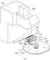
- Fig.1 is an illustrative perspective view of a welding system according to an exemplary embodiment of the present invention
- Fig.2 shows a first fixture 410, a second fixture 420, a first moving mechanism 510 and a second moving mechanism 520 of the welding system of Fig. 1 .
- the welding system is configured to weld a first elongated element 10, for example, a first wire, and a second elongated element 20, for example, a second wire, together.
- the welding system mainly comprises: a first moving mechanism 510; a first fixture 410 adapted to fix the first elongated element 10; a second moving mechanism 520; a second fixture 420 adapted to fix the second elongated element 20; and a laser welding head 100 adapted to emit a laser beam 110 (see Figs.3 and 4 ).
- the first fixture 410 is mounted on the first moving mechanism 510, and the first fixture 410 may be moved by the first moving mechanism 510, so that the first elongated element 10 fixed on the first fixture 410 may be aligned with the second elongated element 20 fixed on the second fixture 420.
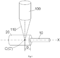
- Fig.3 shows the first elongated element 10, the second elongated element 20 aligned with the first elongated element 10, and the laser welding head 100, in which an ideal welding center point C' of the aligned first and second elongated elements 10, 20 and a focal point C of the laser beam 110 are shown; and Fig.4 is an illustrative view of moving the ideal welding center point C' of the aligned first and second elongated elements 10, 20 of Fig.3 to the focal point C of the laser beam 110.
- the first moving mechanism 510 and the second fixture 420 are mounted on the second moving mechanism 520, and the second moving mechanism 520 is configured to move the first moving mechanism 510 and the second fixture 420 which are mounted on the second moving mechanism 520, so that the ideal welding center point C' of the aligned first and second elongated elements 10, 20 is accurately located at the focal point C of the laser beam 110 from the laser welding head 100 (see Figs.3 and 4 ).
- the welding system may further comprise a vision device 200.
- the first moving mechanism 510 is adapted to move the first elongated element 10 fixed on the first fixture 410 under the guidance of the vision device 200 until the first elongated element 10 is aligned with the second elongated element 20. Thereby, the first elongated element 10 may be automatically moved to precisely align with the second elongated element 20 by the first moving mechanism 510 under the guidance of the vision device 200.
- the second moving mechanism 520 is adapted to move the aligned first and second elongated elements 10, 20 under the guidance of the vision device 200 until the ideal welding center point C' of the aligned first and second elongated elements 10, 20 is accurately located at the focal point C of the laser beam 110 emitted from the laser welding head 100.
- the ideal welding center point C' of the aligned first and second elongated elements 10, 20 may be automatically and precisely moved to the focal point C of the laser beam 110 emitted from the laser welding head 100 by the second moving mechanism 520 under the guidance of the vision device 200, and it ensures the welding quality.
- the first elongated element 10 and the second elongated element 20 have a common center axis X, and end faces of the first elongated element 10 and the second elongated element 20 abut against each other.
- the welding system may further comprise a protective gas injection device (not shown).
- the protective gas injection device is adapted to spray a protective gas to a welding area of the first elongated element 10 and the second elongated element 20, so as to protect the first elongated element 10 and the second elongated element 20 from being oxidized during welding the first elongated element 10 and the second elongated element 20 with the laser beam 110.
- the protective gas injection device may be integrated into the laser welding head 100.
- the protective gas injection device is turned on before turning on the laser welding head 100 and is turned off after turning off the laser welding head 100.
- the welding system may further comprise a controller 300, which is adapted to control the power of the laser beam 110 emitted from the laser welding head 100 and the flow of the protective gas sprayed from the protective gas injection device.
- the first elongated element 10 has a diameter less than that of the second elongated element 20.
- the ideal welding center point C' of the aligned first and second elongated elements 10, 20 is located in the second elongated element 20 and on the center axis of the second elongated element 20.
- the ideal welding center point C' is distanced from the end face of the second elongated element 20 by a distance D.
- the distance D may be calculated based on the diameter of the first elongated element 10 and the diameter of the second elongated element 20.
- the laser beam will be distanced from the first elongated element 10 too far, and cannot melt the first elongated element 10, it will cause the welding failure.
- the distance D is too small, the end to be welded of the first elongated element 10 may be completely melt by the laser beam, it will also cause the welding failure.
- it is necessary to properly set the distance D so that ends to be welded of the first elongated element 10 and the second elongated element 20 are partly melt by the laser beam and effectively welded together.
- properly determining the ideal welding center point C' of the aligned first and second elongated elements 10, 20 is very important to ensure the welding quality.
- the ideal welding center point C' of the aligned first and second elongated elements 10, 20 is necessary to be accurately located at the focal point (or referred as the actual welding center point) C of the laser beam 110 emitted from the laser welding head 100, that is, the ideal welding center point C' of the aligned first and second elongated elements 10, 20 is necessary to be accurately moved to the focal point (the actual welding center point) C of the laser beam 110 emitted from the laser welding head 100.
- the vision device 200 is adapted to identify the position of the ideal welding center point C' of the aligned first and second elongated elements 10, 20.
- the controller 300 is adapted to perform a closed-loop feedback control on the second moving mechanism 520 based on the identified position of the ideal welding center point C' until the ideal welding center point C' of the aligned first and second elongated elements 10, 20 is accurately moved to the focal point (the actual welding center point) C of the laser beam 110 emitted from the laser welding head 100, that is, until a position error between the ideal welding center point C' of the aligned first and second elongated elements 10, 20 and the focal point C of the laser beam 110 becomes zero.
- the first moving mechanism 510 is configured as a moving platform adapted to move in a first direction X and a second direction Y perpendicular to the first direction X in a horizontal plane.
- the first moving mechanism 510 comprises a first moving platform 511 adapted to move in the first direction X, and a second moving platform 512 mounted on the first moving platform 511 and adapted to move in the second direction Y.
- the first fixture 410 is mounted on the second moving platform 512 of the first moving mechanism 510.
- the second moving mechanism 520 is configured as a moving platform adapted to move in the first direction X and the second direction Y in the horizontal plane.
- the second moving mechanism 520 comprises a first moving platform 521 adapted to move in the first direction X, and a second moving platform 522 adapted to move in the second direction Y
- the second moving platform 522 of the second moving mechanism 520 is mounted on a base 600
- the first moving platform 521 of the second moving mechanism 520 is mounted on the second moving platform 522 of the second moving mechanism 520.
- the first moving mechanism 510 and the second fixture 420 are mounted on the first moving platform 521 of the second moving mechanism 520.
- the first elongated element 10 is different from the second elongated element 20 in diameter.
- the first fixture 410 and the second fixture 420 are adapted to fix different types of elongated elements.
- the first fixture 410 is adapted to fix a plurality of first elongated elements 10 at the same time
- the second fixture 420 is adapted to fix a plurality of second elongated elements 20 at the same time.
- the first moving mechanism 410 may be used to simultaneously realize the alignment of the plurality of first elongated elements 10 and the plurality of elongated elements 20, it may further improve the welding efficiency.
- the first moving mechanism 510 and the second moving mechanism 520 each is configured to be a moving platform adapted to move in the first direction X and the second direction Y perpendicular to the first direction X in the horizontal plane.
- the present invention is not limited to this, for example, the first moving mechanism 510 and/or the second moving mechanism 520 may comprise a robot having at least two freedoms.
- a method of welding a first elongated element 10 to a second elongated element 20 mainly comprises steps of:
- the above method may further comprise a step of: spraying a protective gas to a welding area of the first elongated element 10 and the second elongated element 20 before turning on the laser welding head 100, so as to protect the first elongated element 10 and the second elongated element 20 from being oxidized during welding.
Landscapes
- Physics & Mathematics (AREA)
- Optics & Photonics (AREA)
- Engineering & Computer Science (AREA)
- Mechanical Engineering (AREA)
- Plasma & Fusion (AREA)
- Laser Beam Processing (AREA)
Abstract
Description
- This application claims the benefit of Chinese Patent Application No.
CN201610380325.6 filed on June 1, 2016 - The present invention relates to a welding system and method, more particularly, relates to a welding system and method adapted to weld a first elongated element and a second elongated element together.
- In the prior art, a pair of elongated elements, for example, a pair of elongated wires, generally are welded together by manual. Firstly, an operator holds the pair of elongated elements by hands; then, the operator watches ends, to be welded together, of the pair of elongated elements by a microscope, and aligns the ends of the pair of elongated elements with each other; then, the operator turns on a laser welding head to weld the aligned ends of the pair of elongated elements together by a laser beam emitted from the laser welding head.
- Obviously, in the prior art, since it needs to align the pair of elongated elements by manual, the welding efficiency is very low. In addition, in the welding process, the operator may be hurt by the laser beam; therefore, there are some security risks. In addition, the welding quality cannot be guaranteed because the manual alignment precision is not stable.
- The present invention has been made to overcome or alleviate at least one aspect of the above mentioned disadvantages.
- According to an aspect of the present invention, there is provided a welding system configured to weld a first elongated element and a second elongated element together. The welding system comprises: a first moving mechanism; a first fixture adapted to fix the first elongated element; a second moving mechanism; a second fixture adapted to fix the second elongated element; and a laser welding head adapted to emit a laser beam. The first fixture is mounted on the first moving mechanism, and the first moving mechanism is configured to move the first fixture, so that the first elongated element fixed on the first fixture is aligned with the second elongated element fixed on the second fixture. The first moving mechanism and the second fixture are mounted on the second moving mechanism, and the second moving mechanism is configured to move the first moving mechanism and the second fixture, so that an ideal welding center point of the aligned first and second elongated elements is accurately located at a focal point of the laser beam from the laser welding head.
- According to an exemplary embodiment, the welding system further comprises a vision device, and the first moving mechanism is adapted to move the first elongated element fixed on the first fixture under the guidance of the vision device until the first elongated element is aligned with the second elongated element.
- According to another exemplary embodiment, the second moving mechanism is adapted to move the aligned first and second elongated elements under the guidance of the vision device until the ideal welding center point of the aligned first and second elongated elements is accurately located at the focal point of the laser beam from the laser welding head.
- According to another exemplary embodiment, the welding system further comprises a protective gas injection device adapted to spray a protective gas to a welding area of the first elongated element and the second elongated element, so as to protect the first elongated element and the second elongated element from being oxidized during welding the first elongated element and the second elongated element with the laser beam.
- According to another exemplary embodiment, the protective gas injection device is turned on before turning on the laser welding head and is turned off after turning off the laser welding head.
- According to another exemplary embodiment, the welding system further comprises a controller adapted to control the power of the laser beam emitted from the laser welding head and the flow of the protective gas sprayed from the protective gas injection device.
- According to another exemplary embodiment, the vision device is adapted to identify the position of the ideal welding center point of the aligned first and second elongated elements; and the controller is adapted to perform a closed-loop feedback control on the second moving mechanism based on the identified position of the ideal welding center point until a position error between the ideal welding center point and the focal point of the laser beam becomes zero.
- According to another exemplary embodiment, after being aligned with each other, the first elongated element and the second elongated element have a common center axis, and end faces of the first elongated element and the second elongated element abut against each other.
- According to another exemplary embodiment, the first moving mechanism and the second moving mechanism each is configured to be a moving platform adapted to move in a first direction and a second direction perpendicular to the first direction in a horizontal plane.
- According to another exemplary embodiment, the first moving mechanism comprises a first moving platform adapted to move in the first direction, and a second moving platform mounted on the first moving platform and adapted to move in the second direction; and the first fixture is mounted on the second moving platform of the first moving mechanism.
- According to another exemplary embodiment, the second moving mechanism comprises a first moving platform adapted to move in the first direction, and a second moving platform adapted to move in the second direction; the second moving platform of the second moving mechanism is mounted on a base, and the first moving platform of the second moving mechanism is mounted on the second moving platform of the second moving mechanism; and the first moving mechanism and the second fixture are mounted on the first moving platform of the second moving mechanism.
- According to another exemplary embodiment, the first elongated element is different from the second elongated element in diameter, and the first fixture and the second fixture are adapted to fix different types of elongated elements.
- According to another exemplary embodiment, the first fixture is adapted to fix a plurality of first elongated elements at the same time, and the second fixture is adapted to fix a plurality of second elongated elements at the same time.
- According to another exemplary embodiment, the first elongated element and the second elongated element each comprises a wire.
- According to another exemplary embodiment, at least one of the first moving mechanism and the second moving mechanism comprises a robot having at least two freedoms.
- According to another aspect of the present invention, there is provided a method of welding a first elongated element to a second elongated element, comprising steps of:
- S100: providing the above welding system;
- S200: fixing the first elongated element and the second elongated element on the first fixture and the second fixture, respectively;
- S300: moving the first fixture by the first moving mechanism until the first elongated element fixed on the first fixture is aligned with the second elongated element fixed on the second fixture;
- S400: moving the first moving mechanism and the second fixture by the second moving mechanism until an ideal welding center point of the aligned first and second elongated elements is accurately located at a focal point of the laser beam from the laser welding head; and
- S500: turning on the laser welding head to weld the first elongated element and the second elongated element together.
- According to an exemplary embodiment, the method may further comprise a step of:
- spraying a protective gas to a welding area of the first elongated element and the second elongated element before turning on the laser welding head, so as to protect the first elongated element and the second elongated element from being oxidized during welding.
- In the above various exemplary embodiments of the present invention, the alignment operation of a pair of elongated elements may be realized quickly and accurately by the first moving mechanism. Also, the ideal welding center point of the aligned first and second elongated elements may be quickly and accurately moved to the focal point of the laser beam emitted from the laser welding head by the second moving mechanism. Thereby, it improves the welding efficiency and the welding accuracy of the pair of elongated elements.
- The above and other features of the present invention will become more apparent by describing in detail exemplary embodiments thereof with reference to the accompanying drawings, in which:
-
Fig.1 is an illustrative perspective view of a welding system according to an exemplary embodiment of the present invention; -
Fig.2 shows a first fixture, a second fixture, a first moving mechanism and a second moving mechanism of the welding system ofFig.1 ; -
Fig.3 shows a first elongated element, a second elongated element aligned to the first elongated element, and a laser welding head, in which an ideal welding center point of the aligned first and second elongated elements and a focal point of the laser beam are shown; and -
Fig.4 is an illustrative view of moving the ideal welding center point of the aligned first and second elongated elements ofFig.3 to the focal point of the laser beam. - Exemplary embodiments of the present disclosure will be described hereinafter in detail with reference to the attached drawings, wherein the like reference numerals refer to the like elements. The present disclosure may, however, be embodied in many different forms and should not be construed as being limited to the embodiment set forth herein; rather, these embodiments are provided so that the present disclosure will be thorough and complete, and will fully convey the concept of the disclosure to those skilled in the art.
- In the following detailed description, for purposes of explanation, numerous specific details are set forth in order to provide a thorough understanding of the disclosed embodiments. It will be apparent, however, that one or more embodiments may be practiced without these specific details. In other instances, well-known structures and devices are schematically shown in order to simplify the drawing.
- According to a general concept of the present invention, there is provided a welding system configured to weld a first elongated element and a second elongated element together. The welding system comprises: a first moving mechanism; a first fixture adapted to fix the first elongated element; a second moving mechanism; a second fixture adapted to fix the second elongated element; and a laser welding head adapted to emit a laser beam. The first fixture is mounted on the first moving mechanism, and the first moving mechanism is configured to move the first fixture, so that the first elongated element fixed on the first fixture is aligned with the second elongated element fixed on the second fixture. The first moving mechanism and the second fixture are mounted on the second moving mechanism, and the second moving mechanism is configured to move the first moving mechanism and the second fixture, so that an ideal welding center point of the aligned first and second elongated elements is accurately located at a focal point of the laser beam from the laser welding head.
-
Fig.1 is an illustrative perspective view of a welding system according to an exemplary embodiment of the present invention; andFig.2 shows afirst fixture 410, asecond fixture 420, afirst moving mechanism 510 and asecond moving mechanism 520 of the welding system ofFig. 1 . - As shown in
Figs.1 and2 , in an embodiment, the welding system is configured to weld a firstelongated element 10, for example, a first wire, and a secondelongated element 20, for example, a second wire, together. - As shown in
Figs.1 and2 , in an embodiment, the welding system mainly comprises: afirst moving mechanism 510; afirst fixture 410 adapted to fix the firstelongated element 10; asecond moving mechanism 520; asecond fixture 420 adapted to fix the secondelongated element 20; and alaser welding head 100 adapted to emit a laser beam 110 (seeFigs.3 and4 ). - As shown in
Figs.1 and2 , in an embodiment, thefirst fixture 410 is mounted on thefirst moving mechanism 510, and thefirst fixture 410 may be moved by thefirst moving mechanism 510, so that the firstelongated element 10 fixed on thefirst fixture 410 may be aligned with the secondelongated element 20 fixed on thesecond fixture 420. -
Fig.3 shows the firstelongated element 10, the secondelongated element 20 aligned with the firstelongated element 10, and thelaser welding head 100, in which an ideal welding center point C' of the aligned first and secondelongated elements laser beam 110 are shown; andFig.4 is an illustrative view of moving the ideal welding center point C' of the aligned first and secondelongated elements Fig.3 to the focal point C of thelaser beam 110. - As shown in
Figs.1-4 , in an embodiment, thefirst moving mechanism 510 and thesecond fixture 420 are mounted on thesecond moving mechanism 520, and thesecond moving mechanism 520 is configured to move thefirst moving mechanism 510 and thesecond fixture 420 which are mounted on thesecond moving mechanism 520, so that the ideal welding center point C' of the aligned first and secondelongated elements laser beam 110 from the laser welding head 100 (seeFigs.3 and4 ). - As shown in
Figs. 1 and2 , in an embodiment, the welding system may further comprise avision device 200. Thefirst moving mechanism 510 is adapted to move the firstelongated element 10 fixed on thefirst fixture 410 under the guidance of thevision device 200 until the firstelongated element 10 is aligned with the secondelongated element 20. Thereby, the firstelongated element 10 may be automatically moved to precisely align with the secondelongated element 20 by the first movingmechanism 510 under the guidance of thevision device 200. - As shown in
Figs.1-4 , in an embodiment, thesecond moving mechanism 520 is adapted to move the aligned first and secondelongated elements vision device 200 until the ideal welding center point C' of the aligned first and secondelongated elements laser beam 110 emitted from thelaser welding head 100. Thereby, the ideal welding center point C' of the aligned first and secondelongated elements laser beam 110 emitted from thelaser welding head 100 by thesecond moving mechanism 520 under the guidance of thevision device 200, and it ensures the welding quality. - As shown in
Figs.3 and4 , in an embodiment, after the firstelongated element 10 is aligned with the secondelongated element 20, the firstelongated element 10 and the secondelongated element 20 have a common center axis X, and end faces of the firstelongated element 10 and the secondelongated element 20 abut against each other. - Although it is not shown, in an exemplary embodiment of the present invention, the welding system may further comprise a protective gas injection device (not shown). The protective gas injection device is adapted to spray a protective gas to a welding area of the first
elongated element 10 and the secondelongated element 20, so as to protect the firstelongated element 10 and the secondelongated element 20 from being oxidized during welding the firstelongated element 10 and the secondelongated element 20 with thelaser beam 110. - In an embodiment, the protective gas injection device may be integrated into the
laser welding head 100. - In an embodiment, in order to effectively protect the first
elongated element 10 and the secondelongated element 20, the protective gas injection device is turned on before turning on thelaser welding head 100 and is turned off after turning off thelaser welding head 100. - As shown in
Fig.1 , in an embodiment, the welding system may further comprise acontroller 300, which is adapted to control the power of thelaser beam 110 emitted from thelaser welding head 100 and the flow of the protective gas sprayed from the protective gas injection device. - As shown in
Figs.3 and4 , in an embodiment, the firstelongated element 10 has a diameter less than that of the secondelongated element 20. Thereby, as shown inFig.3 , the ideal welding center point C' of the aligned first and secondelongated elements elongated element 20 and on the center axis of the secondelongated element 20. As shown inFig.3 , the ideal welding center point C' is distanced from the end face of the secondelongated element 20 by a distance D. In an embodiment, the distance D may be calculated based on the diameter of the firstelongated element 10 and the diameter of the secondelongated element 20. In practice, if the distance D is too large, the laser beam will be distanced from the firstelongated element 10 too far, and cannot melt the firstelongated element 10, it will cause the welding failure. On the other hand, if the distance D is too small, the end to be welded of the firstelongated element 10 may be completely melt by the laser beam, it will also cause the welding failure. Thereby, it is necessary to properly set the distance D, so that ends to be welded of the firstelongated element 10 and the secondelongated element 20 are partly melt by the laser beam and effectively welded together. Thereby, properly determining the ideal welding center point C' of the aligned first and secondelongated elements - As a result, in an embodiment, in order to ensure the welding quality, the ideal welding center point C' of the aligned first and second
elongated elements laser beam 110 emitted from thelaser welding head 100, that is, the ideal welding center point C' of the aligned first and secondelongated elements laser beam 110 emitted from thelaser welding head 100. - As shown in
Figs.1-4 , in an embodiment, thevision device 200 is adapted to identify the position of the ideal welding center point C' of the aligned first and secondelongated elements controller 300 is adapted to perform a closed-loop feedback control on thesecond moving mechanism 520 based on the identified position of the ideal welding center point C' until the ideal welding center point C' of the aligned first and secondelongated elements laser beam 110 emitted from thelaser welding head 100, that is, until a position error between the ideal welding center point C' of the aligned first and secondelongated elements laser beam 110 becomes zero. - As shown in
Figs.1 and2 , in an embodiment, the first movingmechanism 510 is configured as a moving platform adapted to move in a first direction X and a second direction Y perpendicular to the first direction X in a horizontal plane. Thefirst moving mechanism 510 comprises a first movingplatform 511 adapted to move in the first direction X, and a second movingplatform 512 mounted on the first movingplatform 511 and adapted to move in the second direction Y. Thefirst fixture 410 is mounted on the second movingplatform 512 of the first movingmechanism 510. - As shown in
Figs.1 and2 , in an embodiment, thesecond moving mechanism 520 is configured as a moving platform adapted to move in the first direction X and the second direction Y in the horizontal plane. Thesecond moving mechanism 520 comprises a first movingplatform 521 adapted to move in the first direction X, and a second movingplatform 522 adapted to move in the second direction Y The second movingplatform 522 of thesecond moving mechanism 520 is mounted on abase 600, the first movingplatform 521 of thesecond moving mechanism 520 is mounted on the second movingplatform 522 of thesecond moving mechanism 520. Thefirst moving mechanism 510 and thesecond fixture 420 are mounted on the first movingplatform 521 of thesecond moving mechanism 520. - As shown in
Figs.1-4 , in an embodiment, the firstelongated element 10 is different from the secondelongated element 20 in diameter. Thereby, thefirst fixture 410 and thesecond fixture 420 are adapted to fix different types of elongated elements. - In an embodiment, the
first fixture 410 is adapted to fix a plurality of firstelongated elements 10 at the same time, and thesecond fixture 420 is adapted to fix a plurality of secondelongated elements 20 at the same time. In this way, the first movingmechanism 410 may be used to simultaneously realize the alignment of the plurality of firstelongated elements 10 and the plurality ofelongated elements 20, it may further improve the welding efficiency. - In the illustrated embodiment, the first moving
mechanism 510 and thesecond moving mechanism 520 each is configured to be a moving platform adapted to move in the first direction X and the second direction Y perpendicular to the first direction X in the horizontal plane. But the present invention is not limited to this, for example, the first movingmechanism 510 and/or thesecond moving mechanism 520 may comprise a robot having at least two freedoms. - In another exemplary embodiment of the present invention, there is also provided a method of welding a first
elongated element 10 to a secondelongated element 20. The method mainly comprises steps of: - S100: providing the above welding system as shown in
Figs.1-4 ; - S200: fixing the first
elongated element 10 and the secondelongated element 20 on thefirst fixture 410 and thesecond fixture 420, respectively; - S300: moving the
first fixture 410 by the first movingmechanism 510 until the firstelongated element 10 fixed on thefirst fixture 410 is aligned with the secondelongated element 20 fixed on thesecond fixture 420; - S400: moving the first moving
mechanism 510 and thesecond fixture 420 by thesecond moving mechanism 520 until an ideal welding center point C' of the aligned first and secondelongated elements laser beam 110 from thelaser welding head 100; and - S500: turning on the
laser welding head 100 to weld the firstelongated element 10 and the secondelongated element 20 together. - In an embodiment, the above method may further comprise a step of: spraying a protective gas to a welding area of the first
elongated element 10 and the secondelongated element 20 before turning on thelaser welding head 100, so as to protect the firstelongated element 10 and the secondelongated element 20 from being oxidized during welding. - It should be appreciated for those skilled in this art that the above embodiments are intended to be illustrated, and not restrictive. For example, many modifications may be made to the above embodiments by those skilled in this art, and various features described in different embodiments may be freely combined with each other without conflicting in configuration or principle.
- Although several exemplary embodiments have been shown and described, it would be appreciated by those skilled in the art that various changes or modifications may be made in these embodiments without departing from the principles and spirit of the disclosure, the scope of which is defined in the claims and their equivalents.
- As used herein, an element recited in the singular and proceeded with the word "a" or "an" should be understood as not excluding plural of said elements or steps, unless such exclusion is explicitly stated. Furthermore, references to "one embodiment" of the present invention are not intended to be interpreted as excluding the existence of additional embodiments that also incorporate the recited features. Moreover, unless explicitly stated to the contrary, embodiments "comprising" or "having" an element or a plurality of elements having a particular property may include additional such elements not having that property.
Claims (17)
- A welding system configured to weld a first elongated element (10) and a second elongated element (20) together, and comprising:a first moving mechanism (510);a first fixture (410) adapted to fix the first elongated element (10);a second moving mechanism (520);a second fixture (420) adapted to fix the second elongated element (20); anda laser welding head (100) adapted to emit a laser beam (110),wherein the first fixture (410) is mounted on the first moving mechanism (510), and the first moving mechanism (510) is configured to move the first fixture (410), so that the first elongated element (10) fixed on the first fixture (410) is aligned with the second elongated element (20) fixed on the second fixture (420), andwherein the first moving mechanism (510) and the second fixture (420) are mounted on the second moving mechanism (520), and the second moving mechanism (520) is configured to move the first moving mechanism (510) and the second fixture (420), so that an ideal welding center point (C') of the aligned first and second elongated elements (10, 20) is accurately located at a focal point (C) of the laser beam (110) from the laser welding head (100).
- The welding system according to claim 1,
wherein the welding system further comprises a vision device (200), and the first moving mechanism (510) is adapted to move the first elongated element (10) fixed on the first fixture (410) under the guidance of the vision device (200) until the first elongated element (10) is aligned with the second elongated element (20). - The welding system according to claim 2,
wherein the second moving mechanism (520) is adapted to move the aligned first and second elongated elements (10, 20) under the guidance of the vision device (200) until the ideal welding center point (C') of the aligned first and second elongated elements (10, 20) is accurately located at the focal point (C) of the laser beam (110) from the laser welding head (100). - The welding system according to claim 2 or 3,
wherein the welding system further comprises a protective gas injection device adapted to spray a protective gas to a welding area of the first elongated element (10) and the second elongated element (20), so as to protect the first elongated element (10) and the second elongated element (20) from being oxidized during welding the first elongated element (10) and the second elongated element (20) with the laser beam (110). - The welding system according to claim 4,
wherein the protective gas injection device is turned on before turning on the laser welding head (100) and is turned off after turning off the laser welding head (100). - The welding system according to claim 4 or 5,
wherein the welding system further comprises a controller (300) adapted to control the power of the laser beam (110) emitted from the laser welding head (100) and the flow of the protective gas sprayed from the protective gas injection device. - The welding system according to claim 6,
wherein the vision device (200) is adapted to identify the position of the ideal welding center point (C') of the aligned first and second elongated elements (10, 20); and
wherein the controller (300) is adapted to perform a closed-loop feedback control on the second moving mechanism (520) based on the identified position of the ideal welding center point (C') until a position error between the ideal welding center point (C') and the focal point (C) of the laser beam (110) becomes zero. - The welding system according to one of claims 1 to 7,
wherein, after being aligned with each other, the first elongated element (10) and the second elongated element (20) have a common center axis (X), and end faces of the first elongated element (10) and the second elongated element (20) abut against each other. - The welding system according to one of claims 1 to 8,
wherein the first moving mechanism (510) and the second moving mechanism (520) each is configured as a moving platform adapted to move in a first direction (X) and a second direction (Y) perpendicular to the first direction (X) in a horizontal plane. - The welding system according to claim 9,
wherein the first moving mechanism (510) comprises a first moving platform (511) adapted to move in the first direction (X), and a second moving platform (512) mounted on the first moving platform (511) and adapted to move in the second direction (Y); and
wherein the first fixture (410) is mounted on the second moving platform (512) of the first moving mechanism (510). - The welding system according to claim 10,
wherein the second moving mechanism (520) comprises a first moving platform (521) adapted to move in the first direction (X), and a second moving platform (522) adapted to move in the second direction (Y);
wherein the second moving platform (522) of the second moving mechanism (520) is mounted on a base (600), and the first moving platform (521) of the second moving mechanism (520) is mounted on the second moving platform (522) of the second moving mechanism (520); and
wherein the first moving mechanism (510) and the second fixture (420) are mounted on the first moving platform (521) of the second moving mechanism (520). - The welding system according to one of claims 1 to 11,
wherein the first elongated element (10) is different from the second elongated element (20) in diameter, and the first fixture (410) and the second fixture (420) are adapted to fix different types of elongated elements. - The welding system according to one of claims 1 to 12,
wherein the first fixture (410) is adapted to fix a plurality of first elongated elements (10) at the same time, and the second fixture (420) is adapted to fix a plurality of second elongated elements (20) at the same time. - The welding system according to one of claims 1 to 13,
wherein the first elongated element (10) and the second elongated element (20) each comprises a wire. - The welding system according to one of claims 1 to 14,
wherein at least one of the first moving mechanism (510) and the second moving mechanism (520) comprises a robot having at least two freedoms. - A method of welding a first elongated element (10) to a second elongated element (20), comprising steps of:S100: providing the welding system according to claim 1;S200: fixing the first elongated element (10) and the second elongated element (20) on the first fixture (410) and the second fixture (420), respectively;S300: moving the first fixture (410) by the first moving mechanism (510) until the first elongated element (10) fixed on the first fixture (410) is aligned with the second elongated element (20) fixed on the second fixture (420);S400: moving the first moving mechanism (510) and the second fixture (420) by the second moving mechanism (520) until an ideal welding center point (C') of the aligned first and second elongated elements (10, 20) is accurately located at a focal point (C) of the laser beam (110) from the laser welding head (100); andS500: turning on the laser welding head (100) to weld the first elongated element (10) and the second elongated element (20) together.
- The method according to claim 16, further comprising a step of:spraying a protective gas to a welding area of the first elongated element (10) and the second elongated element (20) before turning on the laser welding head (100), so as to protect the first elongated element (10) and the second elongated element (20) from being oxidized during welding.
Applications Claiming Priority (1)
| Application Number | Priority Date | Filing Date | Title |
|---|---|---|---|
| CN201610380325.6A CN107442933A (en) | 2016-06-01 | 2016-06-01 | Welding system and welding method |
Publications (2)
| Publication Number | Publication Date |
|---|---|
| EP3257618A1 true EP3257618A1 (en) | 2017-12-20 |
| EP3257618B1 EP3257618B1 (en) | 2024-01-24 |
Family
ID=58994850
Family Applications (1)
| Application Number | Title | Priority Date | Filing Date |
|---|---|---|---|
| EP17173364.5A Active EP3257618B1 (en) | 2016-06-01 | 2017-05-30 | Welding system & welding method |
Country Status (3)
| Country | Link |
|---|---|
| US (1) | US10773341B2 (en) |
| EP (1) | EP3257618B1 (en) |
| CN (1) | CN107442933A (en) |
Families Citing this family (5)
| Publication number | Priority date | Publication date | Assignee | Title |
|---|---|---|---|---|
| CN108500461A (en) * | 2018-05-14 | 2018-09-07 | 华南师范大学 | Filamentous metal material laser duct butt-welding method and device |
| CN108723689A (en) * | 2018-08-10 | 2018-11-02 | 隆华科技集团(洛阳)股份有限公司 | A kind of heat exchanger tube clamping method and device for heat exchanger tube butt welding |
| CN112775544A (en) * | 2019-10-22 | 2021-05-11 | 大族激光科技产业集团股份有限公司 | Workpiece welding equipment and method |
| CN116475568B (en) * | 2023-04-20 | 2026-04-03 | 华南理工大学 | A microfilament laser automatic welding device and welding method |
| CN120772418B (en) * | 2025-09-12 | 2025-12-26 | 德州市立尊焊丝有限公司 | Automatic butt joint device and butt joint method for solid welding wires |
Citations (4)
| Publication number | Priority date | Publication date | Assignee | Title |
|---|---|---|---|---|
| US5045668A (en) * | 1990-04-12 | 1991-09-03 | Armco Inc. | Apparatus and method for automatically aligning a welding device for butt welding workpieces |
| WO2011138465A1 (en) * | 2010-05-07 | 2011-11-10 | Transferzentrum Prof. Vogel | Method and device for connecting two wire ends using a sleeve-like retaining element |
| WO2014125993A1 (en) * | 2013-02-14 | 2014-08-21 | 住友化学株式会社 | Cutting device, cutting method, and method of manufacturing laminate optical member |
| US20150343548A1 (en) * | 2014-05-30 | 2015-12-03 | GM Global Technology Operations LLC | Method for joining wire |
Family Cites Families (24)
| Publication number | Priority date | Publication date | Assignee | Title |
|---|---|---|---|---|
| US3036204A (en) * | 1960-04-25 | 1962-05-22 | Seton Corp | Welding machine |
| US4049414A (en) * | 1975-07-28 | 1977-09-20 | Corning Glass Works | Method and apparatus for splicing optical fibers |
| JPS5345644A (en) * | 1976-10-07 | 1978-04-24 | Mitsubishi Electric Corp | Welder |
| JPS55151611A (en) * | 1979-05-16 | 1980-11-26 | Nippon Telegr & Teleph Corp <Ntt> | Optical fiber splicer |
| DE3320121A1 (en) * | 1983-06-03 | 1984-12-06 | Philips Patentverwaltung Gmbh, 2000 Hamburg | Device and method for fusion joining of optical fibres |
| JPS6130287A (en) * | 1984-07-19 | 1986-02-12 | Mitsubishi Electric Corp | Flash welding device |
| JPS63184712A (en) * | 1986-09-26 | 1988-07-30 | Sumitomo Electric Ind Ltd | Optical fiber connection method |
| DE4025351A1 (en) * | 1990-08-10 | 1992-02-13 | Philips Patentverwaltung | DEVICE FOR WELDING TWO GROUPS OF LIGHT-WAVE GUIDES |
| JPH08201641A (en) * | 1995-01-23 | 1996-08-09 | Furukawa Electric Co Ltd:The | Optical fiber clamp mechanism for fusion splicer |
| JP4104769B2 (en) * | 1999-02-25 | 2008-06-18 | 株式会社フジクラ | Optical fiber fusion splicer |
| US6414262B1 (en) * | 1999-11-03 | 2002-07-02 | Nanyang Technological University | Method and apparatus for laser splicing of optical fibers |
| EP1174744A1 (en) * | 2000-07-21 | 2002-01-23 | Corning Incorporated | Method and apparatus for splicing optical fibers |
| DE10119805A1 (en) * | 2001-04-23 | 2002-10-24 | Scc Special Comm Cables Gmbh | Optical waveguide joining device for splicing optical fibers has actuator drive for displacing sliders relative to joining device |
| US7070342B2 (en) * | 2003-03-24 | 2006-07-04 | Aurora Instruments, Inc. | Low profile system for joining optical fiber waveguides |
| JP2004325990A (en) * | 2003-04-28 | 2004-11-18 | Fujikura Ltd | Fusion splicing method of different diameter optical fiber and fusion splicer |
| JP4098677B2 (en) * | 2003-06-26 | 2008-06-11 | 富士通株式会社 | Optical fiber splicer and optical fiber splicing method |
| JP3965477B2 (en) * | 2004-02-23 | 2007-08-29 | Juki株式会社 | Connection method and connection device between optical fiber and optical lens |
| CN2806036Y (en) * | 2005-05-25 | 2006-08-16 | 深圳市比克电池有限公司 | Laser welding assistor for cylindrical battery body |
| BRPI0520237A2 (en) * | 2005-06-06 | 2009-04-28 | Ihi Corp | Method and apparatus for positioning sheet metal elements to be welded butt |
| US20080037939A1 (en) * | 2006-07-31 | 2008-02-14 | The Hong Kong Polytechnic University | Splicing small core photonic crystal fibers and conventional single mode fiber |
| DE102009011037B4 (en) * | 2009-03-02 | 2012-03-15 | Dirk Haussmann | Method and device for welding wires |
| KR101256803B1 (en) * | 2010-12-29 | 2013-04-22 | 주식회사 성우하이텍 | Device for connecting welding wire of co2 gas welding system |
| CN102873457A (en) * | 2012-10-16 | 2013-01-16 | 沈阳市东陵区(浑南新区)卓科技术开发中心 | Back face inert gas protection device for laser welding |
| CN103286451B (en) * | 2013-05-29 | 2015-04-15 | 常熟理工学院 | Laser welding method for Mg-Gr-Y rare-earth magnesium alloy |
-
2016
- 2016-06-01 CN CN201610380325.6A patent/CN107442933A/en active Pending
-
2017
- 2017-05-30 EP EP17173364.5A patent/EP3257618B1/en active Active
- 2017-06-01 US US15/611,020 patent/US10773341B2/en active Active
Patent Citations (4)
| Publication number | Priority date | Publication date | Assignee | Title |
|---|---|---|---|---|
| US5045668A (en) * | 1990-04-12 | 1991-09-03 | Armco Inc. | Apparatus and method for automatically aligning a welding device for butt welding workpieces |
| WO2011138465A1 (en) * | 2010-05-07 | 2011-11-10 | Transferzentrum Prof. Vogel | Method and device for connecting two wire ends using a sleeve-like retaining element |
| WO2014125993A1 (en) * | 2013-02-14 | 2014-08-21 | 住友化学株式会社 | Cutting device, cutting method, and method of manufacturing laminate optical member |
| US20150343548A1 (en) * | 2014-05-30 | 2015-12-03 | GM Global Technology Operations LLC | Method for joining wire |
Also Published As
| Publication number | Publication date |
|---|---|
| EP3257618B1 (en) | 2024-01-24 |
| CN107442933A (en) | 2017-12-08 |
| US20170348800A1 (en) | 2017-12-07 |
| US10773341B2 (en) | 2020-09-15 |
Similar Documents
| Publication | Publication Date | Title |
|---|---|---|
| EP3257618B1 (en) | Welding system & welding method | |
| KR102081743B1 (en) | Auto calibration method for robotic systems | |
| KR100882967B1 (en) | Laser welding device and laser light adjusting method of laser welding device | |
| JP4792901B2 (en) | Laser welding apparatus and method, and irradiation apparatus | |
| JP6472472B2 (en) | Position and orientation adjustment method | |
| KR102511400B1 (en) | Laser beam positioning system, laser processing device and control method | |
| CN106457468B (en) | Hybrid laser welding system and method using two robots | |
| US11637407B2 (en) | Welding system | |
| JP2008043971A (en) | Laser processing apparatus and control method of laser processing apparatus | |
| KR20040106251A (en) | Method of controlling the welding of a three-dimensional construction | |
| JP2012135781A (en) | Method and device for teaching laser machining robot | |
| US10857677B2 (en) | Tip attachment to aid in programming a collaborative robot | |
| EP3090830A1 (en) | Laser welding method | |
| JP2006007304A (en) | Laser cutting method and device and dismantling method using the method and device | |
| JP2020099969A (en) | Positioning device | |
| CN105798459A (en) | Combined laser processing device | |
| US10532426B2 (en) | Laser machining head and origin calibration method for same | |
| JP6125197B2 (en) | Laser fusing device and processing method | |
| JP2011093067A (en) | Visual information support device for hand guide system | |
| US9776278B2 (en) | Laser welder alignment system | |
| JP7113201B1 (en) | LASER PROCESSING APPARATUS AND METHOD FOR ADJUSTING THE FOCUS POSITION OF LASER LIGHT USING THE SAME | |
| JP5741417B2 (en) | Laser processing robot system | |
| JP6131860B2 (en) | Teaching method using laser processing robot system | |
| JP5070719B2 (en) | Laser welding apparatus and laser focus position adjusting method | |
| KR101469205B1 (en) | Method for setting the mobile manipulator onto the workbench |
Legal Events
| Date | Code | Title | Description |
|---|---|---|---|
| PUAI | Public reference made under article 153(3) epc to a published international application that has entered the european phase |
Free format text: ORIGINAL CODE: 0009012 |
|
| STAA | Information on the status of an ep patent application or granted ep patent |
Free format text: STATUS: THE APPLICATION HAS BEEN PUBLISHED |
|
| AK | Designated contracting states |
Kind code of ref document: A1 Designated state(s): AL AT BE BG CH CY CZ DE DK EE ES FI FR GB GR HR HU IE IS IT LI LT LU LV MC MK MT NL NO PL PT RO RS SE SI SK SM TR |
|
| AX | Request for extension of the european patent |
Extension state: BA ME |
|
| STAA | Information on the status of an ep patent application or granted ep patent |
Free format text: STATUS: REQUEST FOR EXAMINATION WAS MADE |
|
| 17P | Request for examination filed |
Effective date: 20180620 |
|
| RBV | Designated contracting states (corrected) |
Designated state(s): AL AT BE BG CH CY CZ DE DK EE ES FI FR GB GR HR HU IE IS IT LI LT LU LV MC MK MT NL NO PL PT RO RS SE SI SK SM TR |
|
| STAA | Information on the status of an ep patent application or granted ep patent |
Free format text: STATUS: EXAMINATION IS IN PROGRESS |
|
| 17Q | First examination report despatched |
Effective date: 20200326 |
|
| REG | Reference to a national code |
Ref legal event code: R079 Ipc: B23Q0001620000 Ref country code: DE Ref document number: 602017078636 Country of ref document: DE Free format text: PREVIOUS MAIN CLASS: B23K0037053000 |
|
| GRAP | Despatch of communication of intention to grant a patent |
Free format text: ORIGINAL CODE: EPIDOSNIGR1 |
|
| STAA | Information on the status of an ep patent application or granted ep patent |
Free format text: STATUS: GRANT OF PATENT IS INTENDED |
|
| RIC1 | Information provided on ipc code assigned before grant |
Ipc: B23K 101/32 20060101ALI20230711BHEP Ipc: B23K 26/03 20060101ALI20230711BHEP Ipc: B23K 37/053 20060101ALI20230711BHEP Ipc: B23K 26/21 20140101ALI20230711BHEP Ipc: B23K 26/08 20140101ALI20230711BHEP Ipc: B23K 26/042 20140101ALI20230711BHEP Ipc: G02B 6/255 20060101ALI20230711BHEP Ipc: B23Q 1/62 20060101AFI20230711BHEP |
|
| RAP3 | Party data changed (applicant data changed or rights of an application transferred) |
Owner name: TE CONNECTIVITY CORPORATION Owner name: MEASUREMENT SPECIALTIES (CHENGDU) LTD Owner name: TYCO ELECTRONICS (SHANGHAI) CO., LTD. |
|
| RIN1 | Information on inventor provided before grant (corrected) |
Inventor name: LU, ROBERTO FRANCISCO-YI Inventor name: YAN, YONG Inventor name: ZENG, QINGLONG Inventor name: LIU, YUN Inventor name: HU, LVHAI Inventor name: ZHANG, DANDAN Inventor name: YING, QIAN Inventor name: GONG, LAN Inventor name: DENG, YINGCONG |
|
| INTG | Intention to grant announced |
Effective date: 20230814 |
|
| RAP3 | Party data changed (applicant data changed or rights of an application transferred) |
Owner name: SHENZEN AMI TECHNOLOGY CO., LTD Owner name: TE CONNECTIVITY CORPORATION Owner name: MEASUREMENT SPECIALTIES (CHENGDU) LTD Owner name: TYCO ELECTRONICS (SHANGHAI) CO., LTD |
|
| RAP1 | Party data changed (applicant data changed or rights of an application transferred) |
Owner name: SHENZEN AMI TECHNOLOGY CO., LTD Owner name: TE CONNECTIVITY SOLUTIONS GMBH Owner name: MEASUREMENT SPECIALTIES (CHENGDU) LTD Owner name: TYCO ELECTRONICS (SHANGHAI) CO., LTD |
|
| GRAS | Grant fee paid |
Free format text: ORIGINAL CODE: EPIDOSNIGR3 |
|
| GRAA | (expected) grant |
Free format text: ORIGINAL CODE: 0009210 |
|
| STAA | Information on the status of an ep patent application or granted ep patent |
Free format text: STATUS: THE PATENT HAS BEEN GRANTED |
|
| AK | Designated contracting states |
Kind code of ref document: B1 Designated state(s): AL AT BE BG CH CY CZ DE DK EE ES FI FR GB GR HR HU IE IS IT LI LT LU LV MC MK MT NL NO PL PT RO RS SE SI SK SM TR |
|
| REG | Reference to a national code |
Ref country code: GB Ref legal event code: FG4D |
|
| REG | Reference to a national code |
Ref country code: CH Ref legal event code: EP |
|
| REG | Reference to a national code |
Ref country code: IE Ref legal event code: FG4D |
|
| REG | Reference to a national code |
Ref country code: DE Ref legal event code: R096 Ref document number: 602017078636 Country of ref document: DE |
|
| REG | Reference to a national code |
Ref country code: LT Ref legal event code: MG9D |
|
| REG | Reference to a national code |
Ref country code: NL Ref legal event code: MP Effective date: 20240124 |
|
| PG25 | Lapsed in a contracting state [announced via postgrant information from national office to epo] |
Ref country code: NL Free format text: LAPSE BECAUSE OF FAILURE TO SUBMIT A TRANSLATION OF THE DESCRIPTION OR TO PAY THE FEE WITHIN THE PRESCRIBED TIME-LIMIT Effective date: 20240124 |
|
| PG25 | Lapsed in a contracting state [announced via postgrant information from national office to epo] |
Ref country code: NL Free format text: LAPSE BECAUSE OF FAILURE TO SUBMIT A TRANSLATION OF THE DESCRIPTION OR TO PAY THE FEE WITHIN THE PRESCRIBED TIME-LIMIT Effective date: 20240124 |
|
| PG25 | Lapsed in a contracting state [announced via postgrant information from national office to epo] |
Ref country code: IS Free format text: LAPSE BECAUSE OF FAILURE TO SUBMIT A TRANSLATION OF THE DESCRIPTION OR TO PAY THE FEE WITHIN THE PRESCRIBED TIME-LIMIT Effective date: 20240524 |
|
| PG25 | Lapsed in a contracting state [announced via postgrant information from national office to epo] |
Ref country code: LT Free format text: LAPSE BECAUSE OF FAILURE TO SUBMIT A TRANSLATION OF THE DESCRIPTION OR TO PAY THE FEE WITHIN THE PRESCRIBED TIME-LIMIT Effective date: 20240124 |
|
| REG | Reference to a national code |
Ref country code: AT Ref legal event code: MK05 Ref document number: 1651810 Country of ref document: AT Kind code of ref document: T Effective date: 20240124 |
|
| PG25 | Lapsed in a contracting state [announced via postgrant information from national office to epo] |
Ref country code: RS Free format text: LAPSE BECAUSE OF FAILURE TO SUBMIT A TRANSLATION OF THE DESCRIPTION OR TO PAY THE FEE WITHIN THE PRESCRIBED TIME-LIMIT Effective date: 20240424 Ref country code: HR Free format text: LAPSE BECAUSE OF FAILURE TO SUBMIT A TRANSLATION OF THE DESCRIPTION OR TO PAY THE FEE WITHIN THE PRESCRIBED TIME-LIMIT Effective date: 20240124 |
|
| PG25 | Lapsed in a contracting state [announced via postgrant information from national office to epo] |
Ref country code: ES Free format text: LAPSE BECAUSE OF FAILURE TO SUBMIT A TRANSLATION OF THE DESCRIPTION OR TO PAY THE FEE WITHIN THE PRESCRIBED TIME-LIMIT Effective date: 20240124 |
|
| PG25 | Lapsed in a contracting state [announced via postgrant information from national office to epo] |
Ref country code: AT Free format text: LAPSE BECAUSE OF FAILURE TO SUBMIT A TRANSLATION OF THE DESCRIPTION OR TO PAY THE FEE WITHIN THE PRESCRIBED TIME-LIMIT Effective date: 20240124 |
|
| PG25 | Lapsed in a contracting state [announced via postgrant information from national office to epo] |
Ref country code: RS Free format text: LAPSE BECAUSE OF FAILURE TO SUBMIT A TRANSLATION OF THE DESCRIPTION OR TO PAY THE FEE WITHIN THE PRESCRIBED TIME-LIMIT Effective date: 20240424 Ref country code: NO Free format text: LAPSE BECAUSE OF FAILURE TO SUBMIT A TRANSLATION OF THE DESCRIPTION OR TO PAY THE FEE WITHIN THE PRESCRIBED TIME-LIMIT Effective date: 20240424 Ref country code: LT Free format text: LAPSE BECAUSE OF FAILURE TO SUBMIT A TRANSLATION OF THE DESCRIPTION OR TO PAY THE FEE WITHIN THE PRESCRIBED TIME-LIMIT Effective date: 20240124 Ref country code: IS Free format text: LAPSE BECAUSE OF FAILURE TO SUBMIT A TRANSLATION OF THE DESCRIPTION OR TO PAY THE FEE WITHIN THE PRESCRIBED TIME-LIMIT Effective date: 20240524 Ref country code: HR Free format text: LAPSE BECAUSE OF FAILURE TO SUBMIT A TRANSLATION OF THE DESCRIPTION OR TO PAY THE FEE WITHIN THE PRESCRIBED TIME-LIMIT Effective date: 20240124 Ref country code: FI Free format text: LAPSE BECAUSE OF FAILURE TO SUBMIT A TRANSLATION OF THE DESCRIPTION OR TO PAY THE FEE WITHIN THE PRESCRIBED TIME-LIMIT Effective date: 20240124 Ref country code: ES Free format text: LAPSE BECAUSE OF FAILURE TO SUBMIT A TRANSLATION OF THE DESCRIPTION OR TO PAY THE FEE WITHIN THE PRESCRIBED TIME-LIMIT Effective date: 20240124 Ref country code: BG Free format text: LAPSE BECAUSE OF FAILURE TO SUBMIT A TRANSLATION OF THE DESCRIPTION OR TO PAY THE FEE WITHIN THE PRESCRIBED TIME-LIMIT Effective date: 20240124 Ref country code: AT Free format text: LAPSE BECAUSE OF FAILURE TO SUBMIT A TRANSLATION OF THE DESCRIPTION OR TO PAY THE FEE WITHIN THE PRESCRIBED TIME-LIMIT Effective date: 20240124 |
|
| PG25 | Lapsed in a contracting state [announced via postgrant information from national office to epo] |
Ref country code: PT Free format text: LAPSE BECAUSE OF FAILURE TO SUBMIT A TRANSLATION OF THE DESCRIPTION OR TO PAY THE FEE WITHIN THE PRESCRIBED TIME-LIMIT Effective date: 20240524 Ref country code: PL Free format text: LAPSE BECAUSE OF FAILURE TO SUBMIT A TRANSLATION OF THE DESCRIPTION OR TO PAY THE FEE WITHIN THE PRESCRIBED TIME-LIMIT Effective date: 20240124 |
|
| PG25 | Lapsed in a contracting state [announced via postgrant information from national office to epo] |
Ref country code: SE Free format text: LAPSE BECAUSE OF FAILURE TO SUBMIT A TRANSLATION OF THE DESCRIPTION OR TO PAY THE FEE WITHIN THE PRESCRIBED TIME-LIMIT Effective date: 20240124 Ref country code: PT Free format text: LAPSE BECAUSE OF FAILURE TO SUBMIT A TRANSLATION OF THE DESCRIPTION OR TO PAY THE FEE WITHIN THE PRESCRIBED TIME-LIMIT Effective date: 20240524 Ref country code: PL Free format text: LAPSE BECAUSE OF FAILURE TO SUBMIT A TRANSLATION OF THE DESCRIPTION OR TO PAY THE FEE WITHIN THE PRESCRIBED TIME-LIMIT Effective date: 20240124 Ref country code: LV Free format text: LAPSE BECAUSE OF FAILURE TO SUBMIT A TRANSLATION OF THE DESCRIPTION OR TO PAY THE FEE WITHIN THE PRESCRIBED TIME-LIMIT Effective date: 20240124 |
|
| PG25 | Lapsed in a contracting state [announced via postgrant information from national office to epo] |
Ref country code: DK Free format text: LAPSE BECAUSE OF FAILURE TO SUBMIT A TRANSLATION OF THE DESCRIPTION OR TO PAY THE FEE WITHIN THE PRESCRIBED TIME-LIMIT Effective date: 20240124 |
|
| PG25 | Lapsed in a contracting state [announced via postgrant information from national office to epo] |
Ref country code: SM Free format text: LAPSE BECAUSE OF FAILURE TO SUBMIT A TRANSLATION OF THE DESCRIPTION OR TO PAY THE FEE WITHIN THE PRESCRIBED TIME-LIMIT Effective date: 20240124 |
|
| PG25 | Lapsed in a contracting state [announced via postgrant information from national office to epo] |
Ref country code: EE Free format text: LAPSE BECAUSE OF FAILURE TO SUBMIT A TRANSLATION OF THE DESCRIPTION OR TO PAY THE FEE WITHIN THE PRESCRIBED TIME-LIMIT Effective date: 20240124 Ref country code: CZ Free format text: LAPSE BECAUSE OF FAILURE TO SUBMIT A TRANSLATION OF THE DESCRIPTION OR TO PAY THE FEE WITHIN THE PRESCRIBED TIME-LIMIT Effective date: 20240124 |
|
| REG | Reference to a national code |
Ref country code: DE Ref legal event code: R097 Ref document number: 602017078636 Country of ref document: DE |
|
| PG25 | Lapsed in a contracting state [announced via postgrant information from national office to epo] |
Ref country code: SK Free format text: LAPSE BECAUSE OF FAILURE TO SUBMIT A TRANSLATION OF THE DESCRIPTION OR TO PAY THE FEE WITHIN THE PRESCRIBED TIME-LIMIT Effective date: 20240124 |
|
| PG25 | Lapsed in a contracting state [announced via postgrant information from national office to epo] |
Ref country code: SM Free format text: LAPSE BECAUSE OF FAILURE TO SUBMIT A TRANSLATION OF THE DESCRIPTION OR TO PAY THE FEE WITHIN THE PRESCRIBED TIME-LIMIT Effective date: 20240124 Ref country code: SK Free format text: LAPSE BECAUSE OF FAILURE TO SUBMIT A TRANSLATION OF THE DESCRIPTION OR TO PAY THE FEE WITHIN THE PRESCRIBED TIME-LIMIT Effective date: 20240124 Ref country code: RO Free format text: LAPSE BECAUSE OF FAILURE TO SUBMIT A TRANSLATION OF THE DESCRIPTION OR TO PAY THE FEE WITHIN THE PRESCRIBED TIME-LIMIT Effective date: 20240124 Ref country code: EE Free format text: LAPSE BECAUSE OF FAILURE TO SUBMIT A TRANSLATION OF THE DESCRIPTION OR TO PAY THE FEE WITHIN THE PRESCRIBED TIME-LIMIT Effective date: 20240124 Ref country code: DK Free format text: LAPSE BECAUSE OF FAILURE TO SUBMIT A TRANSLATION OF THE DESCRIPTION OR TO PAY THE FEE WITHIN THE PRESCRIBED TIME-LIMIT Effective date: 20240124 Ref country code: CZ Free format text: LAPSE BECAUSE OF FAILURE TO SUBMIT A TRANSLATION OF THE DESCRIPTION OR TO PAY THE FEE WITHIN THE PRESCRIBED TIME-LIMIT Effective date: 20240124 |
|
| PLBE | No opposition filed within time limit |
Free format text: ORIGINAL CODE: 0009261 |
|
| STAA | Information on the status of an ep patent application or granted ep patent |
Free format text: STATUS: NO OPPOSITION FILED WITHIN TIME LIMIT |
|
| PG25 | Lapsed in a contracting state [announced via postgrant information from national office to epo] |
Ref country code: IT Free format text: LAPSE BECAUSE OF FAILURE TO SUBMIT A TRANSLATION OF THE DESCRIPTION OR TO PAY THE FEE WITHIN THE PRESCRIBED TIME-LIMIT Effective date: 20240124 |
|
| REG | Reference to a national code |
Ref country code: CH Ref legal event code: PL |
|
| PG25 | Lapsed in a contracting state [announced via postgrant information from national office to epo] |
Ref country code: IT Free format text: LAPSE BECAUSE OF FAILURE TO SUBMIT A TRANSLATION OF THE DESCRIPTION OR TO PAY THE FEE WITHIN THE PRESCRIBED TIME-LIMIT Effective date: 20240124 |
|
| 26N | No opposition filed |
Effective date: 20241025 |
|
| PG25 | Lapsed in a contracting state [announced via postgrant information from national office to epo] |
Ref country code: MC Free format text: LAPSE BECAUSE OF FAILURE TO SUBMIT A TRANSLATION OF THE DESCRIPTION OR TO PAY THE FEE WITHIN THE PRESCRIBED TIME-LIMIT Effective date: 20240124 |
|
| PG25 | Lapsed in a contracting state [announced via postgrant information from national office to epo] |
Ref country code: LU Free format text: LAPSE BECAUSE OF NON-PAYMENT OF DUE FEES Effective date: 20240530 |
|
| GBPC | Gb: european patent ceased through non-payment of renewal fee |
Effective date: 20240530 |
|
| PG25 | Lapsed in a contracting state [announced via postgrant information from national office to epo] |
Ref country code: MC Free format text: LAPSE BECAUSE OF FAILURE TO SUBMIT A TRANSLATION OF THE DESCRIPTION OR TO PAY THE FEE WITHIN THE PRESCRIBED TIME-LIMIT Effective date: 20240124 Ref country code: LU Free format text: LAPSE BECAUSE OF NON-PAYMENT OF DUE FEES Effective date: 20240530 Ref country code: CH Free format text: LAPSE BECAUSE OF NON-PAYMENT OF DUE FEES Effective date: 20240531 |
|
| REG | Reference to a national code |
Ref country code: BE Ref legal event code: MM Effective date: 20240531 |
|
| PG25 | Lapsed in a contracting state [announced via postgrant information from national office to epo] |
Ref country code: IE Free format text: LAPSE BECAUSE OF NON-PAYMENT OF DUE FEES Effective date: 20240530 |
|
| PG25 | Lapsed in a contracting state [announced via postgrant information from national office to epo] |
Ref country code: SI Free format text: LAPSE BECAUSE OF FAILURE TO SUBMIT A TRANSLATION OF THE DESCRIPTION OR TO PAY THE FEE WITHIN THE PRESCRIBED TIME-LIMIT Effective date: 20240124 Ref country code: BE Free format text: LAPSE BECAUSE OF NON-PAYMENT OF DUE FEES Effective date: 20240531 |
|
| PG25 | Lapsed in a contracting state [announced via postgrant information from national office to epo] |
Ref country code: FR Free format text: LAPSE BECAUSE OF NON-PAYMENT OF DUE FEES Effective date: 20240531 |
|
| PG25 | Lapsed in a contracting state [announced via postgrant information from national office to epo] |
Ref country code: GB Free format text: LAPSE BECAUSE OF NON-PAYMENT OF DUE FEES Effective date: 20240530 |
|
| PGFP | Annual fee paid to national office [announced via postgrant information from national office to epo] |
Ref country code: DE Payment date: 20250402 Year of fee payment: 9 |
|
| PG25 | Lapsed in a contracting state [announced via postgrant information from national office to epo] |
Ref country code: GR Free format text: LAPSE BECAUSE OF FAILURE TO SUBMIT A TRANSLATION OF THE DESCRIPTION OR TO PAY THE FEE WITHIN THE PRESCRIBED TIME-LIMIT; INVALID AB INITIO Effective date: 20170530 |
|
| PG25 | Lapsed in a contracting state [announced via postgrant information from national office to epo] |
Ref country code: CY Free format text: LAPSE BECAUSE OF FAILURE TO SUBMIT A TRANSLATION OF THE DESCRIPTION OR TO PAY THE FEE WITHIN THE PRESCRIBED TIME-LIMIT; INVALID AB INITIO Effective date: 20170530 |
|
| PG25 | Lapsed in a contracting state [announced via postgrant information from national office to epo] |
Ref country code: HU Free format text: LAPSE BECAUSE OF FAILURE TO SUBMIT A TRANSLATION OF THE DESCRIPTION OR TO PAY THE FEE WITHIN THE PRESCRIBED TIME-LIMIT; INVALID AB INITIO Effective date: 20170530 |