EP3257428A1 - Signal processing device and signal processing method - Google Patents
Signal processing device and signal processing method Download PDFInfo
- Publication number
- EP3257428A1 EP3257428A1 EP15882031.6A EP15882031A EP3257428A1 EP 3257428 A1 EP3257428 A1 EP 3257428A1 EP 15882031 A EP15882031 A EP 15882031A EP 3257428 A1 EP3257428 A1 EP 3257428A1
- Authority
- EP
- European Patent Office
- Prior art keywords
- endoscope
- determination
- signal
- identification information
- signal processing
- Prior art date
- Legal status (The legal status is an assumption and is not a legal conclusion. Google has not performed a legal analysis and makes no representation as to the accuracy of the status listed.)
- Withdrawn
Links
- 238000003672 processing method Methods 0.000 title claims description 6
- 238000004891 communication Methods 0.000 claims description 10
- 230000002159 abnormal effect Effects 0.000 claims description 7
- 230000006870 function Effects 0.000 description 27
- 238000001514 detection method Methods 0.000 description 22
- 238000001839 endoscopy Methods 0.000 description 17
- 238000002360 preparation method Methods 0.000 description 14
- 230000008859 change Effects 0.000 description 7
- 239000003814 drug Substances 0.000 description 5
- 230000000994 depressogenic effect Effects 0.000 description 4
- 238000000034 method Methods 0.000 description 4
- 230000008569 process Effects 0.000 description 4
- 230000008014 freezing Effects 0.000 description 3
- 238000007710 freezing Methods 0.000 description 3
- 230000000694 effects Effects 0.000 description 2
- 230000002496 gastric effect Effects 0.000 description 2
- 238000003384 imaging method Methods 0.000 description 2
- 238000005086 pumping Methods 0.000 description 2
- 102000001554 Hemoglobins Human genes 0.000 description 1
- 108010054147 Hemoglobins Proteins 0.000 description 1
- 238000000799 fluorescence microscopy Methods 0.000 description 1
- 238000012986 modification Methods 0.000 description 1
- 230000004048 modification Effects 0.000 description 1
- 230000002093 peripheral effect Effects 0.000 description 1
- 238000005375 photometry Methods 0.000 description 1
- 230000009467 reduction Effects 0.000 description 1
- 238000001356 surgical procedure Methods 0.000 description 1
- XLYOFNOQVPJJNP-UHFFFAOYSA-N water Substances O XLYOFNOQVPJJNP-UHFFFAOYSA-N 0.000 description 1
Images



Classifications
-
- A—HUMAN NECESSITIES
- A61—MEDICAL OR VETERINARY SCIENCE; HYGIENE
- A61B—DIAGNOSIS; SURGERY; IDENTIFICATION
- A61B1/00—Instruments for performing medical examinations of the interior of cavities or tubes of the body by visual or photographical inspection, e.g. endoscopes; Illuminating arrangements therefor
- A61B1/00002—Operational features of endoscopes
- A61B1/00057—Operational features of endoscopes provided with means for testing or calibration
-
- A—HUMAN NECESSITIES
- A61—MEDICAL OR VETERINARY SCIENCE; HYGIENE
- A61B—DIAGNOSIS; SURGERY; IDENTIFICATION
- A61B1/00—Instruments for performing medical examinations of the interior of cavities or tubes of the body by visual or photographical inspection, e.g. endoscopes; Illuminating arrangements therefor
- A61B1/00002—Operational features of endoscopes
- A61B1/00004—Operational features of endoscopes characterised by electronic signal processing
- A61B1/00006—Operational features of endoscopes characterised by electronic signal processing of control signals
-
- A—HUMAN NECESSITIES
- A61—MEDICAL OR VETERINARY SCIENCE; HYGIENE
- A61B—DIAGNOSIS; SURGERY; IDENTIFICATION
- A61B1/00—Instruments for performing medical examinations of the interior of cavities or tubes of the body by visual or photographical inspection, e.g. endoscopes; Illuminating arrangements therefor
- A61B1/00002—Operational features of endoscopes
- A61B1/00004—Operational features of endoscopes characterised by electronic signal processing
- A61B1/00009—Operational features of endoscopes characterised by electronic signal processing of image signals during a use of endoscope
-
- A—HUMAN NECESSITIES
- A61—MEDICAL OR VETERINARY SCIENCE; HYGIENE
- A61B—DIAGNOSIS; SURGERY; IDENTIFICATION
- A61B1/00—Instruments for performing medical examinations of the interior of cavities or tubes of the body by visual or photographical inspection, e.g. endoscopes; Illuminating arrangements therefor
- A61B1/00002—Operational features of endoscopes
- A61B1/0002—Operational features of endoscopes provided with data storages
-
- A—HUMAN NECESSITIES
- A61—MEDICAL OR VETERINARY SCIENCE; HYGIENE
- A61B—DIAGNOSIS; SURGERY; IDENTIFICATION
- A61B1/00—Instruments for performing medical examinations of the interior of cavities or tubes of the body by visual or photographical inspection, e.g. endoscopes; Illuminating arrangements therefor
- A61B1/00002—Operational features of endoscopes
- A61B1/00059—Operational features of endoscopes provided with identification means for the endoscope
-
- A—HUMAN NECESSITIES
- A61—MEDICAL OR VETERINARY SCIENCE; HYGIENE
- A61B—DIAGNOSIS; SURGERY; IDENTIFICATION
- A61B1/00—Instruments for performing medical examinations of the interior of cavities or tubes of the body by visual or photographical inspection, e.g. endoscopes; Illuminating arrangements therefor
- A61B1/04—Instruments for performing medical examinations of the interior of cavities or tubes of the body by visual or photographical inspection, e.g. endoscopes; Illuminating arrangements therefor combined with photographic or television appliances
- A61B1/041—Capsule endoscopes for imaging
-
- A—HUMAN NECESSITIES
- A61—MEDICAL OR VETERINARY SCIENCE; HYGIENE
- A61B—DIAGNOSIS; SURGERY; IDENTIFICATION
- A61B1/00—Instruments for performing medical examinations of the interior of cavities or tubes of the body by visual or photographical inspection, e.g. endoscopes; Illuminating arrangements therefor
- A61B1/04—Instruments for performing medical examinations of the interior of cavities or tubes of the body by visual or photographical inspection, e.g. endoscopes; Illuminating arrangements therefor combined with photographic or television appliances
- A61B1/045—Control thereof
-
- G—PHYSICS
- G02—OPTICS
- G02B—OPTICAL ELEMENTS, SYSTEMS OR APPARATUS
- G02B23/00—Telescopes, e.g. binoculars; Periscopes; Instruments for viewing the inside of hollow bodies; Viewfinders; Optical aiming or sighting devices
- G02B23/24—Instruments or systems for viewing the inside of hollow bodies, e.g. fibrescopes
- G02B23/2407—Optical details
- G02B23/2423—Optical details of the distal end
- G02B23/243—Objectives for endoscopes
-
- A—HUMAN NECESSITIES
- A61—MEDICAL OR VETERINARY SCIENCE; HYGIENE
- A61B—DIAGNOSIS; SURGERY; IDENTIFICATION
- A61B1/00—Instruments for performing medical examinations of the interior of cavities or tubes of the body by visual or photographical inspection, e.g. endoscopes; Illuminating arrangements therefor
- A61B1/00112—Connection or coupling means
- A61B1/00121—Connectors, fasteners and adapters, e.g. on the endoscope handle
-
- G—PHYSICS
- G02—OPTICS
- G02B—OPTICAL ELEMENTS, SYSTEMS OR APPARATUS
- G02B23/00—Telescopes, e.g. binoculars; Periscopes; Instruments for viewing the inside of hollow bodies; Viewfinders; Optical aiming or sighting devices
- G02B23/24—Instruments or systems for viewing the inside of hollow bodies, e.g. fibrescopes
- G02B23/2476—Non-optical details, e.g. housings, mountings, supports
Definitions
- the present invention relates to a signal processing device that an endoscope is connected to, and a signal processing method thereof.
- an endoscope system used in endoscopy in internal medicine includes an endoscope, an endoscope video processor, a monitor device, and a peripheral device (an image recording device or the like), and the endoscope system is used in a state in which the above respective devices are connected to the endoscope video processor.
- an endoscope used in endoscopy needs to be removed after the endoscopy, and a cleaned endoscope needs to be installed before the next endoscopy. Stated another way, an endoscope needs to be attached and detached to an endoscope video processor in every endoscopy.
- pre-examination preparation such as an input of examinee data (patient data) or the like to the endoscope system or checking of an operation needed in examination of the endoscope system
- checking the operation of the endoscope system an operation member (for example, a button allocated as a release button) that is included in an endoscope is operated, and operation checking is performed so as to check, for example, whether an operation according to an operation performed on the operation member (for example, a release operation) is normally performed.
- pre-examination preparation cannot be completed in a state in which an endoscope is not connected to an endoscope video processor (for example, a state in which an endoscope used in the previous endoscopy has been removed and a cleaned endoscope has not yet been installed).
- Patent Document 1 describes an electronic endoscope device that is capable of inputting patient data or the like and preparing for setup or the like even when an electronic endoscope is not connected to a processor device.
- the electronic endoscope device when it is determined that an electronic endoscope including a clock generator is not connected, an auxiliary clock generator on a side of the processor device, not a clock generator on a side of the electronic endoscope, is selected and used, and various functions on the side of the processor device are enabled according to a clock signal that is output from the auxiliary clock generator. Accordingly, without the electronic endoscope, patient data or the like can be input from a keyboard or the like, setup such as adjustment of a monitor can be performed, and preparation for endoscopy or the like can be performed smoothly.
- Patent Document 1 Japanese Laid-Open Patent Publication No. 2001-87222
- a signal processing device includes: a connection detector that detects whether an endoscope including one or more operation members is connected; a signal selector that selects an operation state signal that is input from the endoscope when the connection detector detects that the endoscope is connected, and that selects an operation state signal that is input from an external input device including one or more operation members that correspond to the one or more operation members of the endoscope when the connection detector detects that the endoscope is not connected; an allocation information storage unit that stores allocation information relating to an operation that is allocated to each of the one or more operation members; an operation instruction setting unit that sets an operation instruction according to the operation state signal selected by the signal selector in accordance with the operation state signal selected by the signal selector and the allocation information stored in the allocation information storage unit; and an operation execution unit that executes an operation according to the operation instruction set by the operation instruction setting unit.
- the signal processing device in the first aspect further includes a sample image storage unit that stores a sample image, wherein when the connection detector detects that the endoscope is not connected, and the operation instruction set by the operation instruction setting unit is an operation instruction that needs an image obtained from the endoscope, the operation execution unit executes the operation according to the operation instruction by using the sample image stored in the sample image storage unit.
- the signal processing device in the first or second aspect includes: an endoscope identification information storage unit that stores endoscope identification information of each of a plurality of endoscopes; and an endoscope identification information selector that selects one piece of endoscope identification information from among plural pieces of endoscope identification information stored in the endoscope identification information storage unit, wherein the allocation information storage unit stores the allocation information relating to the operation that is allocated to each of the one or more operation members for each of the plural pieces of endoscope identification information, and when the connection detector detects that the endoscope is not connected, the operation instruction setting unit sets an operation instruction of corresponding endoscope identification information according to the operation state signal selected by the signal selector in accordance with the operation state signal selected by the signal selector, the allocation information stored in the allocation information storage unit, and the endoscope identification information selected by the endoscope identification information selector, the endoscope identification information being input from the external input device.
- the allocation information storage unit stores the allocation information relating to the operation that is allocated to each of the one or more operation members for
- the signal processing device in any one of the first to third aspects further includes a determination unit that, at the time of operation checking, performs any one or more of the first determination of whether a communication path to a connected recording device or recording medium is abnormal, the second determination of whether the connected recording device or recording medium is uncoincident with a recording device or recording medium that is set in advance to be an image recording destination, the third determination of whether an image has failed to be read from the connected recording device or recording medium, and the fourth determination of whether a free recording space of the connected recording device or recording medium is smaller than or equal to a prescribed space.
- the signal processing device in the fourth aspect further includes an error reporting unit that reports an error when a result of any one of the first determination to the fourth determination performed by the determination unit is true.
- the signal processing device in the fourth or fifth aspect is provided that further incudes a determination result storage unit that stores a result of any one or more of the first determination to the fourth determination performed by the determination unit.
- the signal processing device in the sixth aspect is provided wherein, at the time of operation checking, when all results of the previous first determination to the previous fourth determination that are stored in the determination result storage unit are false, an image recording operation is omitted from an operation including the image recording operation that the operation execution unit will execute next time.
- the signal processing device in the sixth or seventh aspect is provided wherein, at the time of operation checking, when all results of the previous first determination to the previous third determination that are stored in the determination result storage unit are false, and when a result of the previous fourth determination is true, the first determination to the third determination are not performed, but the fourth determination is performed in the next determination performed by the determination unit.
- a signal processing method in which a signal processing device performs: detecting whether an endoscope including one or more operation members is connected; selecting an operation state signal that is input from the endoscope when it is detected that the endoscope is connected, and selecting an operation state signal that is input from an external input device including one or more operation members that correspond to the one or more operation members of the endoscope when it is detected that the endoscope is not connected; setting an operation instruction according to the selected operation state signal in accordance with the selected operation state signal and allocation information relating to an operation that is allocated to each of the operation members; and executing an operation according to the set operation instruction.
- the present invention exhibits an effect whereby an operation that is performed according to an operation performed on an operation member of an endoscope can be checked even in a state in which the endoscope is not connected.
- a signal processing device is included in an endoscope system used in endoscopy, for example, in internal medicine (gastrointestinal medicine or the like).
- FIG. 1 illustrates an exemplary configuration of an endoscope system including an endoscope video processor that is a signal processing device according to an embodiment of the present invention.
- an endoscope system 100 includes a scope (an endoscope) 200, an external interface 300, an endoscope video processor (hereinafter simply referred to as a "processor") 400, a monitor device (hereinafter simply referred to as a "monitor”) 500, and an image recording device 600, and the endoscope system 100 has a configuration in which the scope 200 and/or the external interface 300, the monitor 500, and the image recording device 600 are connected to the processor 400.
- processing is performed, for example, such that a portion of the scope 200 is inserted into the body of an examinee, an observation region inside the body of the examinee is imaged by the scope 200, a captured image is processed by the processor 400, and the processed image is displayed on the monitor 500, or is recorded in the image recording device 600.
- the scope 200 includes an operation unit that is operated by an examiner or the like.
- the operation unit includes one or more buttons, and an operation performed by the processor 400 is allocated in advance to each of the buttons.
- the operation allocated to each of the buttons can be changed arbitrarily. Operations that can be allocated to the respective buttons are classified into an operation that needs an image (a video signal) obtained from the scope 200 and an operation that does not need the image (the video signal) obtained from the scope 200.
- Examples of the former operation include freezing, releasing, capturing, marking releasing, electronic magnification, focusing, a change in the size of an image, displaying a distribution of an index of hemoglobin (IHb), image enhancement, a change in color, a change in contrast, noise reduction, picture-in-picture (PIP)/picture-on-picture (POP) display, auto gain control (AGC), and video recording
- examples of the latter operation include a change in a photometry scheme, a change in a light amount of a light source, switching display information, clocking, rotating a turret for special light observation (such as narrow band imaging (NBI), auto-fluorescence imaging (AFI), or intra-red imaging (IRI)), and feeding air (water) by using a pump.
- NBI narrow band imaging
- AFI auto-fluorescence imaging
- IRI intra-red imaging
- the external interface 300 is, for example, a portable information terminal device such as a tablet terminal, or a keyboard, and the external interface 300 includes an operation unit that is operated by an examiner or the like.
- the operation unit includes one or more buttons that correspond to one or more buttons included in the operation unit of the scope 200, and an operation that is similar to the operation allocated to each of the buttons of the scope 200 is allocated to each of the buttons of the external interface 300.
- the buttons of the external interface 300 may be physical buttons, or may be virtual buttons that are realized by a touch panel or the like.
- the processor 400 includes a scope connection detection circuit 410, an internal signal switching circuit 420, a non-volatile memory 430, a field-programmable gate array (FPGA) 440, and a function execution circuit 450.
- a scope connection detection circuit 410 an internal signal switching circuit 420, a non-volatile memory 430, a field-programmable gate array (FPGA) 440, and a function execution circuit 450.
- FPGA field-programmable gate array
- the scope connection detection circuit 410 detects whether the scope 200 is connected to the processor 400 (connection or non-connection of the scope 200). Connection or non-connection is detected, for example, by detecting whether there is a connection signal that is input from the scope 200.
- the internal signal switching circuit 420 switches an input signal according to a detection result of the scope connection detection circuit 410. More specifically, when the scope connection detection circuit 410 detects that the scope 200 is connected, the internal signal switching circuit 420 switches an input signal in such a way that an operation state signal that is input from the scope 200 is output to the FPGA 440. When the scope connection detection circuit 410 detects that the scope 200 is not connected, the internal signal switching circuit 420 switches an input signal in such a way that an operation state signal that is input from the external interface 300 is output to the FPGA 440. Accordingly, the internal signal switching circuit 420 selects an operation state signal that is input from the scope 200 or the external interface 300 in accordance with a detection result of the scope connection detection circuit 410, and outputs the selected operation state signal to the FPGA 440.
- the operation state signal that is input from the scope 200 is a signal indicating an operation state of each of the buttons of the scope 200
- the operation state signal that is input from the external interface 300 is a signal indicating an operation state of each of the buttons of the external interface 300.
- the operation state of each of the buttons also refers to a depression state of each of the buttons, or the ON state or the OFF state of a switch of each of the buttons. Control is performed in such a way that an operation state signal that is input from the scope 200 when a button of the scope 200 is operated is the same as an operation state signal that is input from the external interface 300 when a button of the external interface 300 that corresponds to the button of the scope 200 is operated.
- an operation state signal that is input from the scope 200 when a button A of the scope 200 is depressed is the same as an operation state signal that is input from the external interface 300 when a buttons A' of the external interface 300 that corresponds to the button A is depressed.
- an operation state signal that is input from the external interface 300 is a pseudo operation state signal that is input from the scope 200.
- the non-volatile memory 430 includes an allocation information storage area 431 that stores allocation information relating to an operation that is allocated to each of the buttons of the scope 200 (this is also each of the buttons of the external interface 300), and a sample image storage area 432 that stores a sample image.
- the sample image is a still image or a moving image, and is also a two-dimensional image (a 2D image) or a three-dimensional image (a 3D image) .
- the sample image is, for example, an image that is generated within the processor 400.
- the FPGA 440 includes a central processing unit (CPU) 441 and a register 442.
- the CPU 441 performs various types of control processing. As an example, the CPU 441 sets, in the register 442, an operation instruction (an instruction to perform or not perform each operation) according to an operation state signal that is output from the internal signal switching circuit 420, in accordance with the operation state signal and the allocation information stored in the allocation information storage area 431 of the non-volatile memory 430.
- an operation instruction an instruction to perform or not perform each operation
- the CPU 441 performs control so as to output, to the function execution circuit 450, the sample image stored in the sample image storage area 432 of the non-volatile memory 430 as the image obtained from the scope 200.
- the function execution circuit 450 performs an operation according to an operation instruction set by the CPU 441 of the FPGA 440. More specifically, the function execution circuit 450 monitors the register 442 of the FPGA 440, and performs an operation that has been set to be performed in the register 442. In this case, when the scope connection detection circuit 410 detects that the scope 200 is not connected, and the operation instruction that has been set in the register 442 by the CPU 441 of the FPGA 440 is an operation instruction that needs an image obtained from the scope 200 (for example, an instruction to perform releasing or the like), the function execution circuit 450 performs an operation according to the operation instruction by using a sample image that is output from the sample image storage area 432 of the non-volatile memory 430.
- the monitor 500 displays an image, various types of data, or the like.
- the monitor 500 displays a result of the function execution circuit 450 performing an operation (success or failure in performing an operation, an image obtained by performing an operation, or the like), examinee data, or the like.
- the image recording device 600 records an image, various types of data, or the like.
- the image recording device 600 records a result of the function execution circuit 450 performing an operation (for example, an image obtained by performing an operation), examinee data, or the like.
- the scope 200 including one or more buttons is an example of an endoscope including one or more operation members.
- the external interface 300 including one or more buttons that correspond to the one or more buttons of the scope 200 is an example of an external input device including one or more operation members that correspond to the one or more operation members of the endoscope.
- the scope connection detection circuit 410 of the processor 400 is an example of a connection detector that detects whether the endoscope including one or more operation members is connected.
- the internal signal switching circuit 420 of the processor 400 is an example of a signal selector that selects an operation state signal that is input from the endoscope when the connection detector detects that the endoscope is connected, and that selects an operation state signal that is input from the external input device including one or more operation members that correspond to the one or more operation members of the endoscope when the connection detector detects that the endoscope is not connected.
- the allocation information storage area 431 of the non-volatile memory 430 of the processor 400 is an example of an allocation information storage unit that stores allocation information relating to an operation that is allocated to each of the operation members.
- Some functions of the CPU 441 of the FPGA 440 of the processor 400 are examples of an operation instruction setting unit that sets an operation instruction according to an operation state signal selected by the signal selector in accordance with the operation state signal selected by the signal selector and the allocation information stored in the allocation information storage unit.
- the function execution circuit 450 of the processor 400 is an example of an operation execution unit that executes an operation according to the operation instruction set by the operation instruction setting unit.
- the sample image storage area 432 of the non-volatile memory 430 of the processor 400 is an example of a sample image storage unit that stores a sample image.
- the following processing is performed, for example, at the time of checking an operation of the endoscope system 100 in pre-examination preparation for endoscopy.
- the scope connection detection circuit 410 detects whether the scope 200 is connected to the processor 400 (connection or non-connection of the scope 200).
- the internal signal switching circuit 420 switches an input signal according to a detection result of the scope connection detection circuit 410. More specifically, when the scope connection detection circuit 410 detects that the scope 200 is connected, the internal signal switching circuit 420 switches an input signal in such a way that an operation state signal that is input from the scope 200 is output to the FPGA 440, and when the scope connection detection circuit 410 detects that the scope 200 is not connected, the internal signal switching circuit 420 switches an input signal in such a way that an operation state signal that is input from the external interface 300 is output to the FPGA 440.
- the CPU 441 of the FPGA 440 sets, in the register 442, an operation instruction (an instruction to perform or not perform each operation) according to the operation state signal that is output from the internal signal switching circuit 420 in accordance with the operation state signal and the allocation information stored in the allocation information storage area 431 of the non-volatile memory 430.
- the CPU 441 performs control so as to output, to the function execution circuit 450, a sample image stored in the sample image storage area 432 of the non-volatile memory 430 as the image obtained from the scope 200.
- the function execution circuit 450 that monitors the register 442 of the FPGA 440 performs an operation according to the operation instruction that has been set in the register 442 (an operation that has been set to be performed in the register 442).
- the function execution circuit 450 performs an operation according to the operation instruction by using a sample image that is output from the sample image storage area 432 of the non-volatile memory 430.
- An execution result of the function execution circuit 450 is displayed on the monitor 500, or is recorded in the image recording device 600.
- the processor 400 that is a signal processing device according to the embodiment, even in a case in which the scope 200 is not connected to the processor 400 at the time of checking an operation of the endoscope system 100 in pre-examination preparation for endoscopy, when the external interface 300 is connected to the processor 400, an operation of the processor 400 that is performed according to an operation performed on a button of the scope 200 can be performed by operating a corresponding button of the external interface 300. Accordingly, a conventional problem can be solved wherein checking an operation of the endoscope system 100 cannot be completed in pre-examination preparation because the scope 200 is not connected.
- the endoscope system 100 including the processor 400 that is a signal processing device according to the embodiment.
- the following variation can be made to the endoscope system 100 in such a way that an examiner or the like can freely associate a button of the external interface 300 with a desired button of a scope.
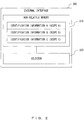
- the external interface 300 includes the non-volatile memory 310 and the selector 320, as illustrated in FIG. 2 , for example.
- the non-volatile memory 310 stores respective pieces of identification information (identification information A, identification information B, and identification information C) of a plurality of scopes (in this example, assume that the plurality of scopes are three scopes, a scope A, a scope B, and a scope B) .
- the selector 320 selects identification information of one scope from among respective pieces of identification information of the plurality of scopes that are stored in the non-volatile memory 310, in accordance with a prescribed operation that an examiner or the like performs on the external interface 300.
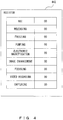
- the allocation information storage area 431 of the non-volatile memory 430 of the processor 400 stores allocation information relating to an operation that is allocated to each of the buttons for each of the pieces of identification information of the scopes, as illustrated in FIG. 3 , for example.
- NBI rotating a turret for NBI
- releasing, and freezing are respectively allocated to a button A, a button B, and a button C of the scope A that corresponds to the identification information A.
- Pumping, electronic magnification, and image enhancement are respectively allocated to a button A, a button B, and a button C of the scope B that corresponds to the identification information B.
- Focusing, video recording, and capturing are respectively allocated to a button A, a button B, and a button C of the scope C that corresponds to the identification information C.
- An instruction to perform or not perform each operation is set in the register 442 of the FPGA 440 of the processor 400, as illustrated in FIG. 4 , for example.
- an instruction to perform or not perform each of the operations NBI (rotating a turret for NBI), releasing, freezing, pumping, electronic magnification, image enhancement, focusing, video recording, and capturing, is set.
- NBI rotating a turret for NBI
- releasing freezing, pumping, electronic magnification, image enhancement, focusing, video recording, and capturing
- NBI rotating a turret for NBI
- releasing freezing, pumping, electronic magnification, image enhancement, focusing, video recording, and capturing
- the following processing is performed, for example.
- the selector 320 selects identification information of a scope to be used in the next examination in accordance with a prescribed operation performed by an examiner or the like.
- the selected identification information of the scope is reported to the CPU 441 of the FPGA 440 of the processor 400.
- the scope connection detection circuit 410 detects that a scope is not connected to the processor 400 (non-connection of a scope).
- the internal signal switching circuit 420 switches an input signal according to a detection result (non-connection of a scope) of the scope connection detection circuit 410 in such a way that an operation state signal that is input from the external interface 300 is output from the FPGA 440.
- the CPU 441 of the FPGA 440 sets, in the register 442, an operation instruction of a scope of corresponding identification information (an instruction to perform or not perform an operation that is allocated to each of the buttons of the scope of the corresponding identification information) according to the operation state signal that is output from the internal signal switching circuit 420 in accordance with the operation state signal, the allocation information stored in the allocation information storage area 431 of the non-volatile memory 430 (see FIG. 3 ), and the identification information of the scope that is reported from the external interface 300.
- an operation instruction of a scope of corresponding identification information an instruction to perform or not perform an operation that is allocated to each of the buttons of the scope of the corresponding identification information
- NBI in the register 442 illustrated in FIG. 4 is set to "01".
- electronic magnification in the register 442 illustrated in FIG. 4 is set to "01".
- an operation instruction according to the operation state signal that is output from the internal signal switching circuit 420 is an operation instruction that needs an image obtained from a scope (for example, an instruction to perform the above electronic magnification or the like)
- the CPU 441 performs control so as to output, to the function execution circuit 450, a sample image stored in the sample image storage area 432 of the non-volatile memory 430 as the image obtained from a scope.
- an examiner or the like can freely associate a button of the external interface 300 with a desired button of a scope, and can make the processor 400 perform an operation according to an operation that is performed on the desired button of the scope by operating the button of the external interface 300.
- the non-volatile memory 310 of the external interface 300 is an example of an endoscope identification information storage unit that stores respective pieces of endoscope identification information of a plurality of endoscopes.
- the selector 320 of the external interface 300 is an example of an endoscope identification information selector that selects one piece of endoscope identification information from among plural pieces of endoscope identification information stored in the endoscope identification information storage unit.
- a further variation may be made in such a way that the CPU 441 of the FPGA 440 performs the following processing, for example, in order to reduce a load on an examiner or the like at the time of checking an operation of the endoscope system 100 in pre-examination preparation.
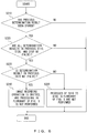
- FIG. 5 is a flowchart illustrating an example of the processing content. This processing is processing that is started, for example, after the function execution circuit 450 performs an operation including an image recording operation (for example, releasing, capturing, recording, and the like) at the time of checking of an operation of the endoscope system 100 in pre-examination preparation.
- an image recording operation for example, releasing, capturing, recording, and the like
- the CPU 441 first determines whether a communication line (a communication path) to a recording device or a recording medium that is connected to the processor 400 is abnormal (S110) .
- the recording device that is connected to the processor 400 is, for example, the image recording device 600 above, or a recording device that is connected to the processor 400 via a network.
- the recording medium that is connected to the processor 400 is, for example, a universal serial bus (USB) memory.
- USB universal serial bus
- the determination result in S110 is regarded as No, and processing is proceeded.
- the CPU 441 performs control so as to display, on the monitor 500, an error report indicating that a communication line between the recording device or recording medium that is connected to the processor 400 and the processor 400 is abnormal (S120).
- the CPU 441 determines whether the recording device or recording medium that is connected to the processor 400 is uncoincident with a recording device or recording medium that has been set to be an image recording destination in the processor 400 (S130) .
- the determination result is Yes.
- the CPU 441 performs control so as to display, on the monitor 500, an error report indicating that the recording device or recording medium that is connected to the processor 400 is uncoincident with a recording device or recording medium that has been set to be an image recording destination in the processor 400 (S140).
- the CPU 441 determines whether an image has failed to be read from the recording device or recording medium that is connected to the processor 400 (S150). In a case in which the recording device or recording medium that is connected to the processor 400 is connected to the processor 400 via a communication line and a video signal line, it is determined in S150 whether the video signal line between the recording device or recording medium that is connected to the processor 400 and the processor 400 is abnormal.
- the CPU 441 performs control so as to display, on the monitor 500, an error report indicating that an image has failed to be read from the recording device or recording medium that is connected to the processor 400 (or an error report indicating that the video signal line between the recording device or recording medium that is connected to the processor 400 and the processor 400 is abnormal) (S160).
- the CPU 441 determines whether a free recording space of the recording device or recording medium that is connected to the processor 400 is smaller than or equal to a prescribed space (S170).
- the prescribed space is a recording space that is smaller than a recording space that is needed for at least one endoscopy.
- the CPU 441 performs control so as to display, on the monitor 500, an error report indicating that the free recording space of the recording device or recording medium that is connected to the processor 400 is smaller than or equal to a prescribed space (an error report indicating that a free recording space is insufficient) (S180).
- the CPU 441 performs control so as to display, on the monitor 500, a report indicating that image recording has been normally performed (S190).
- an examiner or the like can easily specify the cause of failure in image recording at the time of checking an operation of the endoscope system 100 in pre-examination preparation, and a load on the examiner or the like at the time of checking the operation of the endoscope system 100 can be reduced.
- a function of the CPU 441 for performing the processing illustrated in FIG. 5 is an example of a determination unit that performs any one or more of first determination of whether a communication path to a connected recording device or recording medium is abnormal, second determination of whether the connected recording device or recording medium is uncoincident with a recording device or recording medium that has been set to be an image recording destination, third determination of whether an image has failed to be read from the connected recording device or recording medium, and fourth determination of whether a free recording space of the connected recording device or recording medium is smaller than or equal to a prescribed space, at the time of operation checking.
- the monitor 500 is an example of an error reporting unit that reports an error when a result of any one of the first determination to the fourth determination performed by the determination unit is true.
- the CPU 441 of the FPGA 440 may perform control so as to store a determination result of determination processing performed in the flowchart of FIG. 5 in a determination result storage area included in the non-volatile memory 430, and may further perform the following processing.
- FIG. 6 is a flowchart illustrating an example of the processing content. This processing is processing that is started, for example, before the function execution circuit 450 performs an operation including an image recording operation at the time of checking an operation of the endoscope system 100 in pre-examination preparation.
- the CPU 441 first determines whether a previous determination result has been stored in the determination result storage area of the non-volatile memory 430 (S210).
- the CPU 441 determines whether all of the determination results in the previous S110, S130, and S150 are No (false) in accordance with the previous determination result stored in the determination result storage area of the non-volatile memory 430 (S220).
- the CPU 441 determines whether a determination result in the previous S170 is No (false) in accordance with the previous determination result stored in the determination result storage area of the non-volatile memory 430 (S230).
- the CPU 441 controls the function execution circuit 450 to omit an image recording operation from an operation including the image recording operation that the function execution circuit 450 will perform next time, and also controls the function execution circuit 450 to not perform the processing in the flowchart illustrated in FIG. 5 after an operation in which the image recording operation is omitted (S240).
- the CPU 441 performs control to omit the processes of S110 to S160 and to perform only the processes of S170 to S190 in the processing in the flowchart illustrated in FIG. 5 that is performed after an operation including the image recording operation that the function execution circuit 450 will perform next time (S250) . Namely, the CPU 441 performs control to only determine a free recording space and perform processing according to a determination result.
- an examiner or the like does not need to confirm the image recording operation or to confirm a free recording space of a recording device or recording medium that is connected to the processor 400 every time an operation including the image recording operation is performed. Accordingly, a load on the examiner or the like at the time of checking the operation of the endoscope system 100 can be reduced. In addition, the time needed to check the operation of the endoscope system 100 can be reduced.
- the determination result storage area included in the non-volatile memory 430 of the processor 400 is an example of a determination result storage unit that stores a result of any one or more of the first determination to the fourth determination performed by the determination unit.
- a plurality of recording destinations such as a plurality of recording devices or a plurality of recording media, or one or more recording devices and one or more recording media, may be connected as image recording destinations to the processor 400 that is a signal processing device according to the embodiment.
- the operation above that is performed on one recording destination (for example, the image recording device 600) may be performed on each of the connected recording destinations.
- the processor 400 that is a signal processing device according to the embodiment may be configured to be integrated with the external interface 300.
- the external interface 300 is configured to be, for example, a front panel of the processor 400.
Landscapes
- Health & Medical Sciences (AREA)
- Life Sciences & Earth Sciences (AREA)
- Surgery (AREA)
- Physics & Mathematics (AREA)
- Engineering & Computer Science (AREA)
- Optics & Photonics (AREA)
- Biophysics (AREA)
- Animal Behavior & Ethology (AREA)
- Pathology (AREA)
- Radiology & Medical Imaging (AREA)
- Veterinary Medicine (AREA)
- Biomedical Technology (AREA)
- Heart & Thoracic Surgery (AREA)
- Medical Informatics (AREA)
- Molecular Biology (AREA)
- Nuclear Medicine, Radiotherapy & Molecular Imaging (AREA)
- General Health & Medical Sciences (AREA)
- Public Health (AREA)
- Signal Processing (AREA)
- Astronomy & Astrophysics (AREA)
- General Physics & Mathematics (AREA)
- Endoscopes (AREA)
- Instruments For Viewing The Inside Of Hollow Bodies (AREA)
Abstract
Description
- The present invention relates to a signal processing device that an endoscope is connected to, and a signal processing method thereof.
- Conventionally, endoscope systems are used in medical fields such as internal medicine or surgery. As an example, an endoscope system used in endoscopy in internal medicine (gastrointestinal medicine or the like) includes an endoscope, an endoscope video processor, a monitor device, and a peripheral device (an image recording device or the like), and the endoscope system is used in a state in which the above respective devices are connected to the endoscope video processor.
- In the endoscope system used in endoscopy, a cleaned endoscope needs to be used in every endoscopy. Therefore, an endoscope used in endoscopy needs to be removed after the endoscopy, and a cleaned endoscope needs to be installed before the next endoscopy. Stated another way, an endoscope needs to be attached and detached to an endoscope video processor in every endoscopy.
- In addition, in the endoscope system used in endoscopy, pre-examination preparation, such as an input of examinee data (patient data) or the like to the endoscope system or checking of an operation needed in examination of the endoscope system, is performed before endoscopy. As an example, in checking the operation of the endoscope system, an operation member (for example, a button allocated as a release button) that is included in an endoscope is operated, and operation checking is performed so as to check, for example, whether an operation according to an operation performed on the operation member (for example, a release operation) is normally performed. When there are no problems in the pre-examination preparation, endoscopy is actually started.
- Under the actual situation above, pre-examination preparation cannot be completed in a state in which an endoscope is not connected to an endoscope video processor (for example, a state in which an endoscope used in the previous endoscopy has been removed and a cleaned endoscope has not yet been installed).
- On the other hand, as an example, Patent Document 1 describes an electronic endoscope device that is capable of inputting patient data or the like and preparing for setup or the like even when an electronic endoscope is not connected to a processor device. In the electronic endoscope device, when it is determined that an electronic endoscope including a clock generator is not connected, an auxiliary clock generator on a side of the processor device, not a clock generator on a side of the electronic endoscope, is selected and used, and various functions on the side of the processor device are enabled according to a clock signal that is output from the auxiliary clock generator. Accordingly, without the electronic endoscope, patient data or the like can be input from a keyboard or the like, setup such as adjustment of a monitor can be performed, and preparation for endoscopy or the like can be performed smoothly.
- Patent Document 1: Japanese Laid-Open Patent Publication No.
2001-87222 - In the electronic endoscope device described in Patent Document 1, various functions on the side of the processor device can be enabled (for example, setup such as adjustment of a monitor can be performed) even when the electronic endoscope is not connected to the processor device. However, checking an operation that is performed according to an operation performed on an operation member included in an endoscope, as performed in checking the operation of an endoscope system in the pre-examination preparation above, cannot be performed.
- In view of the foregoing, it is an object of the present invention to provide a signal processing device that can check an operation that is performed according to an operation performed on an operation member included in an endoscope even in a state in which the endoscope is not connected, and a signal processing method thereof.
- In the first aspect of the present invention, a signal processing device is provided that includes: a connection detector that detects whether an endoscope including one or more operation members is connected; a signal selector that selects an operation state signal that is input from the endoscope when the connection detector detects that the endoscope is connected, and that selects an operation state signal that is input from an external input device including one or more operation members that correspond to the one or more operation members of the endoscope when the connection detector detects that the endoscope is not connected; an allocation information storage unit that stores allocation information relating to an operation that is allocated to each of the one or more operation members; an operation instruction setting unit that sets an operation instruction according to the operation state signal selected by the signal selector in accordance with the operation state signal selected by the signal selector and the allocation information stored in the allocation information storage unit; and an operation execution unit that executes an operation according to the operation instruction set by the operation instruction setting unit.
- In the second aspect of the present invention, the signal processing device in the first aspect is provided that further includes a sample image storage unit that stores a sample image, wherein when the connection detector detects that the endoscope is not connected, and the operation instruction set by the operation instruction setting unit is an operation instruction that needs an image obtained from the endoscope, the operation execution unit executes the operation according to the operation instruction by using the sample image stored in the sample image storage unit.
- In the third aspect of the present invention, the signal processing device in the first or second aspect is provided wherein the external input device includes: an endoscope identification information storage unit that stores endoscope identification information of each of a plurality of endoscopes; and an endoscope identification information selector that selects one piece of endoscope identification information from among plural pieces of endoscope identification information stored in the endoscope identification information storage unit, wherein the allocation information storage unit stores the allocation information relating to the operation that is allocated to each of the one or more operation members for each of the plural pieces of endoscope identification information, and when the connection detector detects that the endoscope is not connected, the operation instruction setting unit sets an operation instruction of corresponding endoscope identification information according to the operation state signal selected by the signal selector in accordance with the operation state signal selected by the signal selector, the allocation information stored in the allocation information storage unit, and the endoscope identification information selected by the endoscope identification information selector, the endoscope identification information being input from the external input device.
- In the fourth aspect of the present invention, the signal processing device in any one of the first to third aspects is provided that further includes a determination unit that, at the time of operation checking, performs any one or more of the first determination of whether a communication path to a connected recording device or recording medium is abnormal, the second determination of whether the connected recording device or recording medium is uncoincident with a recording device or recording medium that is set in advance to be an image recording destination, the third determination of whether an image has failed to be read from the connected recording device or recording medium, and the fourth determination of whether a free recording space of the connected recording device or recording medium is smaller than or equal to a prescribed space.
- In the fifth aspect of the present invention, the signal processing device in the fourth aspect is provided that further includes an error reporting unit that reports an error when a result of any one of the first determination to the fourth determination performed by the determination unit is true.
- In the sixth aspect of the present invention, the signal processing device in the fourth or fifth aspect is provided that further incudes a determination result storage unit that stores a result of any one or more of the first determination to the fourth determination performed by the determination unit.
- In the seventh aspect of the present invention, the signal processing device in the sixth aspect is provided wherein, at the time of operation checking, when all results of the previous first determination to the previous fourth determination that are stored in the determination result storage unit are false, an image recording operation is omitted from an operation including the image recording operation that the operation execution unit will execute next time.
- In the eighth aspect of the present invention, the signal processing device in the sixth or seventh aspect is provided wherein, at the time of operation checking, when all results of the previous first determination to the previous third determination that are stored in the determination result storage unit are false, and when a result of the previous fourth determination is true, the first determination to the third determination are not performed, but the fourth determination is performed in the next determination performed by the determination unit.
- In the ninth aspect of the present invention, a signal processing method is provided in which a signal processing device performs: detecting whether an endoscope including one or more operation members is connected; selecting an operation state signal that is input from the endoscope when it is detected that the endoscope is connected, and selecting an operation state signal that is input from an external input device including one or more operation members that correspond to the one or more operation members of the endoscope when it is detected that the endoscope is not connected; setting an operation instruction according to the selected operation state signal in accordance with the selected operation state signal and allocation information relating to an operation that is allocated to each of the operation members; and executing an operation according to the set operation instruction.
- The present invention exhibits an effect whereby an operation that is performed according to an operation performed on an operation member of an endoscope can be checked even in a state in which the endoscope is not connected.
-
-
FIG. 1 illustrates an exemplary configuration of an endoscope system including an endoscope video processor that is a signal processing device according to an embodiment. -
FIG. 2 illustrates an example of an external interface according to a variation. -
FIG. 3 illustrates an example of an allocation information storage area according to a variation. -
FIG. 4 illustrates an example of a register according to a variation. -
FIG. 5 is a flowchart illustrating an example of the processing content of a CPU according to a variation. -
FIG. 6 is a flowchart illustrating an example of the processing content of a CPU according to a variation. - Embodiments of the present invention are described below with reference to the drawings.
- A signal processing device according to an embodiment of the present invention is included in an endoscope system used in endoscopy, for example, in internal medicine (gastrointestinal medicine or the like).
-
FIG. 1 illustrates an exemplary configuration of an endoscope system including an endoscope video processor that is a signal processing device according to an embodiment of the present invention. - As illustrated in
FIG. 1 , anendoscope system 100 includes a scope (an endoscope) 200, anexternal interface 300, an endoscope video processor (hereinafter simply referred to as a "processor") 400, a monitor device (hereinafter simply referred to as a "monitor") 500, and animage recording device 600, and theendoscope system 100 has a configuration in which thescope 200 and/or theexternal interface 300, themonitor 500, and theimage recording device 600 are connected to theprocessor 400. - In the
endoscope system 100 described above, processing is performed, for example, such that a portion of thescope 200 is inserted into the body of an examinee, an observation region inside the body of the examinee is imaged by thescope 200, a captured image is processed by theprocessor 400, and the processed image is displayed on themonitor 500, or is recorded in theimage recording device 600. - In the
endoscope system 100, thescope 200 includes an operation unit that is operated by an examiner or the like. The operation unit includes one or more buttons, and an operation performed by theprocessor 400 is allocated in advance to each of the buttons. The operation allocated to each of the buttons can be changed arbitrarily. Operations that can be allocated to the respective buttons are classified into an operation that needs an image (a video signal) obtained from thescope 200 and an operation that does not need the image (the video signal) obtained from thescope 200. Examples of the former operation include freezing, releasing, capturing, marking releasing, electronic magnification, focusing, a change in the size of an image, displaying a distribution of an index of hemoglobin (IHb), image enhancement, a change in color, a change in contrast, noise reduction, picture-in-picture (PIP)/picture-on-picture (POP) display, auto gain control (AGC), and video recording, and examples of the latter operation include a change in a photometry scheme, a change in a light amount of a light source, switching display information, clocking, rotating a turret for special light observation (such as narrow band imaging (NBI), auto-fluorescence imaging (AFI), or intra-red imaging (IRI)), and feeding air (water) by using a pump. - The
external interface 300 is, for example, a portable information terminal device such as a tablet terminal, or a keyboard, and theexternal interface 300 includes an operation unit that is operated by an examiner or the like. The operation unit includes one or more buttons that correspond to one or more buttons included in the operation unit of thescope 200, and an operation that is similar to the operation allocated to each of the buttons of thescope 200 is allocated to each of the buttons of theexternal interface 300. The buttons of theexternal interface 300 may be physical buttons, or may be virtual buttons that are realized by a touch panel or the like. - The
processor 400 includes a scopeconnection detection circuit 410, an internalsignal switching circuit 420, anon-volatile memory 430, a field-programmable gate array (FPGA) 440, and afunction execution circuit 450. - The scope
connection detection circuit 410 detects whether thescope 200 is connected to the processor 400 (connection or non-connection of the scope 200). Connection or non-connection is detected, for example, by detecting whether there is a connection signal that is input from thescope 200. - The internal
signal switching circuit 420 switches an input signal according to a detection result of the scopeconnection detection circuit 410. More specifically, when the scopeconnection detection circuit 410 detects that thescope 200 is connected, the internalsignal switching circuit 420 switches an input signal in such a way that an operation state signal that is input from thescope 200 is output to theFPGA 440. When the scopeconnection detection circuit 410 detects that thescope 200 is not connected, the internalsignal switching circuit 420 switches an input signal in such a way that an operation state signal that is input from theexternal interface 300 is output to theFPGA 440. Accordingly, the internalsignal switching circuit 420 selects an operation state signal that is input from thescope 200 or theexternal interface 300 in accordance with a detection result of the scopeconnection detection circuit 410, and outputs the selected operation state signal to theFPGA 440. - The operation state signal that is input from the
scope 200 is a signal indicating an operation state of each of the buttons of thescope 200, and the operation state signal that is input from theexternal interface 300 is a signal indicating an operation state of each of the buttons of theexternal interface 300. The operation state of each of the buttons also refers to a depression state of each of the buttons, or the ON state or the OFF state of a switch of each of the buttons. Control is performed in such a way that an operation state signal that is input from thescope 200 when a button of thescope 200 is operated is the same as an operation state signal that is input from theexternal interface 300 when a button of theexternal interface 300 that corresponds to the button of thescope 200 is operated. Accordingly, as an example, an operation state signal that is input from thescope 200 when a button A of thescope 200 is depressed is the same as an operation state signal that is input from theexternal interface 300 when a buttons A' of theexternal interface 300 that corresponds to the button A is depressed. Thus, it can be said that an operation state signal that is input from theexternal interface 300 is a pseudo operation state signal that is input from thescope 200. - The
non-volatile memory 430 includes an allocationinformation storage area 431 that stores allocation information relating to an operation that is allocated to each of the buttons of the scope 200 (this is also each of the buttons of the external interface 300), and a sampleimage storage area 432 that stores a sample image. The sample image is a still image or a moving image, and is also a two-dimensional image (a 2D image) or a three-dimensional image (a 3D image) . The sample image is, for example, an image that is generated within theprocessor 400. - The
FPGA 440 includes a central processing unit (CPU) 441 and aregister 442. - The
CPU 441 performs various types of control processing. As an example, theCPU 441 sets, in theregister 442, an operation instruction (an instruction to perform or not perform each operation) according to an operation state signal that is output from the internalsignal switching circuit 420, in accordance with the operation state signal and the allocation information stored in the allocationinformation storage area 431 of thenon-volatile memory 430. In this case, when the scopeconnection detection circuit 410 detects that thescope 200 is not connected, and the operation instruction according to the operation state signal that is output from the internalsignal switching circuit 420 is an operation instruction that needs an image obtained from the scope 200 (for example, an instruction to perform releasing or the like), theCPU 441 performs control so as to output, to thefunction execution circuit 450, the sample image stored in the sampleimage storage area 432 of thenon-volatile memory 430 as the image obtained from thescope 200. - An instruction to perform or not perform each operation is set in the
register 442. - The
function execution circuit 450 performs an operation according to an operation instruction set by theCPU 441 of theFPGA 440. More specifically, thefunction execution circuit 450 monitors theregister 442 of theFPGA 440, and performs an operation that has been set to be performed in theregister 442. In this case, when the scopeconnection detection circuit 410 detects that thescope 200 is not connected, and the operation instruction that has been set in theregister 442 by theCPU 441 of theFPGA 440 is an operation instruction that needs an image obtained from the scope 200 (for example, an instruction to perform releasing or the like), thefunction execution circuit 450 performs an operation according to the operation instruction by using a sample image that is output from the sampleimage storage area 432 of thenon-volatile memory 430. - The
monitor 500 displays an image, various types of data, or the like. As an example, themonitor 500 displays a result of thefunction execution circuit 450 performing an operation (success or failure in performing an operation, an image obtained by performing an operation, or the like), examinee data, or the like. - The
image recording device 600 records an image, various types of data, or the like. As an example, theimage recording device 600 records a result of thefunction execution circuit 450 performing an operation (for example, an image obtained by performing an operation), examinee data, or the like. - In the
endoscope system 100 having the configuration above, thescope 200 including one or more buttons is an example of an endoscope including one or more operation members. Theexternal interface 300 including one or more buttons that correspond to the one or more buttons of thescope 200 is an example of an external input device including one or more operation members that correspond to the one or more operation members of the endoscope. The scopeconnection detection circuit 410 of theprocessor 400 is an example of a connection detector that detects whether the endoscope including one or more operation members is connected. The internalsignal switching circuit 420 of theprocessor 400 is an example of a signal selector that selects an operation state signal that is input from the endoscope when the connection detector detects that the endoscope is connected, and that selects an operation state signal that is input from the external input device including one or more operation members that correspond to the one or more operation members of the endoscope when the connection detector detects that the endoscope is not connected. The allocationinformation storage area 431 of thenon-volatile memory 430 of theprocessor 400 is an example of an allocation information storage unit that stores allocation information relating to an operation that is allocated to each of the operation members. Some functions of theCPU 441 of theFPGA 440 of theprocessor 400 are examples of an operation instruction setting unit that sets an operation instruction according to an operation state signal selected by the signal selector in accordance with the operation state signal selected by the signal selector and the allocation information stored in the allocation information storage unit. Thefunction execution circuit 450 of theprocessor 400 is an example of an operation execution unit that executes an operation according to the operation instruction set by the operation instruction setting unit. The sampleimage storage area 432 of thenon-volatile memory 430 of theprocessor 400 is an example of a sample image storage unit that stores a sample image. - In the
processor 400 of theendoscope system 100 having the configuration above, the following processing is performed, for example, at the time of checking an operation of theendoscope system 100 in pre-examination preparation for endoscopy. - First, the scope
connection detection circuit 410 detects whether thescope 200 is connected to the processor 400 (connection or non-connection of the scope 200). - Then, the internal
signal switching circuit 420 switches an input signal according to a detection result of the scopeconnection detection circuit 410. More specifically, when the scopeconnection detection circuit 410 detects that thescope 200 is connected, the internalsignal switching circuit 420 switches an input signal in such a way that an operation state signal that is input from thescope 200 is output to theFPGA 440, and when the scopeconnection detection circuit 410 detects that thescope 200 is not connected, the internalsignal switching circuit 420 switches an input signal in such a way that an operation state signal that is input from theexternal interface 300 is output to theFPGA 440. - The
CPU 441 of theFPGA 440 sets, in theregister 442, an operation instruction (an instruction to perform or not perform each operation) according to the operation state signal that is output from the internalsignal switching circuit 420 in accordance with the operation state signal and the allocation information stored in the allocationinformation storage area 431 of thenon-volatile memory 430. In this case, when the scopeconnection detection circuit 410 detects that thescope 200 is not connected, and the operation instruction according to the operation state signal that is output from the internalsignal switching circuit 420 is an operation instruction that needs an image obtained from the scope 200 (for example, an instruction to perform releasing or the like), theCPU 441 performs control so as to output, to thefunction execution circuit 450, a sample image stored in the sampleimage storage area 432 of thenon-volatile memory 430 as the image obtained from thescope 200. - The
function execution circuit 450 that monitors theregister 442 of theFPGA 440 performs an operation according to the operation instruction that has been set in the register 442 (an operation that has been set to be performed in the register 442). In this case, when the scopeconnection detection circuit 410 detects that thescope 200 is not connected, and the operation instruction that has been set in theregister 442 by theCPU 441 of theFPGA 440 is an operation instruction that needs an image obtained from the scope 200 (for example, an instruction to perform releasing or the like), thefunction execution circuit 450 performs an operation according to the operation instruction by using a sample image that is output from the sampleimage storage area 432 of thenon-volatile memory 430. An execution result of thefunction execution circuit 450 is displayed on themonitor 500, or is recorded in theimage recording device 600. - As described above, by employing the
processor 400 that is a signal processing device according to the embodiment, even in a case in which thescope 200 is not connected to theprocessor 400 at the time of checking an operation of theendoscope system 100 in pre-examination preparation for endoscopy, when theexternal interface 300 is connected to theprocessor 400, an operation of theprocessor 400 that is performed according to an operation performed on a button of thescope 200 can be performed by operating a corresponding button of theexternal interface 300. Accordingly, a conventional problem can be solved wherein checking an operation of theendoscope system 100 cannot be completed in pre-examination preparation because thescope 200 is not connected. - Various variations can be made to the
endoscope system 100 including theprocessor 400 that is a signal processing device according to the embodiment. - As an example, the following variation can be made to the
endoscope system 100 in such a way that an examiner or the like can freely associate a button of theexternal interface 300 with a desired button of a scope. - In this case, the
external interface 300 includes thenon-volatile memory 310 and theselector 320, as illustrated inFIG. 2 , for example. Thenon-volatile memory 310 stores respective pieces of identification information (identification information A, identification information B, and identification information C) of a plurality of scopes (in this example, assume that the plurality of scopes are three scopes, a scope A, a scope B, and a scope B) . Theselector 320 selects identification information of one scope from among respective pieces of identification information of the plurality of scopes that are stored in thenon-volatile memory 310, in accordance with a prescribed operation that an examiner or the like performs on theexternal interface 300. - The allocation
information storage area 431 of thenon-volatile memory 430 of theprocessor 400 stores allocation information relating to an operation that is allocated to each of the buttons for each of the pieces of identification information of the scopes, as illustrated inFIG. 3 , for example. In the example illustrated inFIG. 3 , NBI (rotating a turret for NBI), releasing, and freezing are respectively allocated to a button A, a button B, and a button C of the scope A that corresponds to the identification information A. Pumping, electronic magnification, and image enhancement are respectively allocated to a button A, a button B, and a button C of the scope B that corresponds to the identification information B. Focusing, video recording, and capturing are respectively allocated to a button A, a button B, and a button C of the scope C that corresponds to the identification information C. - An instruction to perform or not perform each operation is set in the
register 442 of theFPGA 440 of theprocessor 400, as illustrated inFIG. 4 , for example. In the example illustrated inFIG. 4 , an instruction to perform or not perform each of the operations, NBI (rotating a turret for NBI), releasing, freezing, pumping, electronic magnification, image enhancement, focusing, video recording, and capturing, is set. In this example, "01" is set as an instruction to perform an operation, and "00" is set as an instruction to not perform an operation. - In the
endoscope system 100 according to the variation above, in a case in which a scope is not connected to theprocessor 400 at the time of checking an operation of theendoscope system 100 in pre-examination preparation for endoscopy, the following processing is performed, for example. - First, in the
external interface 300, theselector 320 selects identification information of a scope to be used in the next examination in accordance with a prescribed operation performed by an examiner or the like. The selected identification information of the scope is reported to theCPU 441 of theFPGA 440 of theprocessor 400. - In the
processor 400, the scopeconnection detection circuit 410 detects that a scope is not connected to the processor 400 (non-connection of a scope). - Then, the internal
signal switching circuit 420 switches an input signal according to a detection result (non-connection of a scope) of the scopeconnection detection circuit 410 in such a way that an operation state signal that is input from theexternal interface 300 is output from theFPGA 440. - The
CPU 441 of theFPGA 440 sets, in theregister 442, an operation instruction of a scope of corresponding identification information (an instruction to perform or not perform an operation that is allocated to each of the buttons of the scope of the corresponding identification information) according to the operation state signal that is output from the internalsignal switching circuit 420 in accordance with the operation state signal, the allocation information stored in the allocationinformation storage area 431 of the non-volatile memory 430 (seeFIG. 3 ), and the identification information of the scope that is reported from theexternal interface 300. As an example, in a case in which the identification information of the scope that is reported from theexternal interface 300 is the identification information A of the scope A, and a button of theexternal interface 300 that corresponds to the button A of the scope A is depressed, NBI in theregister 442 illustrated inFIG. 4 is set to "01". As another example, in a case in which the identification information of the scope that is reported from theexternal interface 300 is the identification information B of the scope B, and a button of theexternal interface 300 that corresponds to the button B of the scope B is depressed, electronic magnification in theregister 442 illustrated inFIG. 4 is set to "01". In this case, in a case in which an operation instruction according to the operation state signal that is output from the internalsignal switching circuit 420 is an operation instruction that needs an image obtained from a scope (for example, an instruction to perform the above electronic magnification or the like), theCPU 441 performs control so as to output, to thefunction execution circuit 450, a sample image stored in the sampleimage storage area 432 of thenon-volatile memory 430 as the image obtained from a scope. - The processing that follows is as described above, and its description is omitted.
- According to the variation above, an examiner or the like can freely associate a button of the
external interface 300 with a desired button of a scope, and can make theprocessor 400 perform an operation according to an operation that is performed on the desired button of the scope by operating the button of theexternal interface 300. - In this variation, the
non-volatile memory 310 of theexternal interface 300 is an example of an endoscope identification information storage unit that stores respective pieces of endoscope identification information of a plurality of endoscopes. Theselector 320 of theexternal interface 300 is an example of an endoscope identification information selector that selects one piece of endoscope identification information from among plural pieces of endoscope identification information stored in the endoscope identification information storage unit. - In the
processor 400 that is a signal processing device according to the embodiment, a further variation may be made in such a way that theCPU 441 of theFPGA 440 performs the following processing, for example, in order to reduce a load on an examiner or the like at the time of checking an operation of theendoscope system 100 in pre-examination preparation. -
FIG. 5 is a flowchart illustrating an example of the processing content. This processing is processing that is started, for example, after thefunction execution circuit 450 performs an operation including an image recording operation (for example, releasing, capturing, recording, and the like) at the time of checking of an operation of theendoscope system 100 in pre-examination preparation. - As illustrated in
FIG. 5 , when this processing is started, theCPU 441 first determines whether a communication line (a communication path) to a recording device or a recording medium that is connected to theprocessor 400 is abnormal (S110) . The recording device that is connected to theprocessor 400 is, for example, theimage recording device 600 above, or a recording device that is connected to theprocessor 400 via a network. The recording medium that is connected to theprocessor 400 is, for example, a universal serial bus (USB) memory. As an example, when communication can be performed between the recording device or recording medium that is connected to theprocessor 400 and theprocessor 400, the determination result in S110 is Yes, and otherwise the determination result is No. In a case in which the recording medium that is connected to theprocessor 400 is a recording medium that does not have a communication function (for example, a USB memory that does not have a communication function), the determination result in S110 is regarded as No, and processing is proceeded. - When the determination result in S110 is Yes, the
CPU 441 performs control so as to display, on themonitor 500, an error report indicating that a communication line between the recording device or recording medium that is connected to theprocessor 400 and theprocessor 400 is abnormal (S120). - When the determination result in S110 is No, the
CPU 441 determines whether the recording device or recording medium that is connected to theprocessor 400 is uncoincident with a recording device or recording medium that has been set to be an image recording destination in the processor 400 (S130) . As an example, when theimage recording device 600 is connected to theprocessor 400, in a case in which a USB memory has been set to be an image recording destination in theprocessor 400, both are uncoincident with each other, and therefore the determination result is Yes. - When the determination result in S130 is Yes, the
CPU 441 performs control so as to display, on themonitor 500, an error report indicating that the recording device or recording medium that is connected to theprocessor 400 is uncoincident with a recording device or recording medium that has been set to be an image recording destination in the processor 400 (S140). - When the determination result in S130 is No, the
CPU 441 determines whether an image has failed to be read from the recording device or recording medium that is connected to the processor 400 (S150). In a case in which the recording device or recording medium that is connected to theprocessor 400 is connected to theprocessor 400 via a communication line and a video signal line, it is determined in S150 whether the video signal line between the recording device or recording medium that is connected to theprocessor 400 and theprocessor 400 is abnormal. - When the determination result in S150 is Yes, the
CPU 441 performs control so as to display, on themonitor 500, an error report indicating that an image has failed to be read from the recording device or recording medium that is connected to the processor 400 (or an error report indicating that the video signal line between the recording device or recording medium that is connected to theprocessor 400 and theprocessor 400 is abnormal) (S160). - When the determination result in S150 is No, the
CPU 441 determines whether a free recording space of the recording device or recording medium that is connected to theprocessor 400 is smaller than or equal to a prescribed space (S170). The prescribed space is a recording space that is smaller than a recording space that is needed for at least one endoscopy. - When the determination result in S170 is Yes, the
CPU 441 performs control so as to display, on themonitor 500, an error report indicating that the free recording space of the recording device or recording medium that is connected to theprocessor 400 is smaller than or equal to a prescribed space (an error report indicating that a free recording space is insufficient) (S180). - When the determination result in S170 is No, the
CPU 441 performs control so as to display, on themonitor 500, a report indicating that image recording has been normally performed (S190). - After S120, S140, S160, S180, or S190, this processing is finished.
- According to the variation above, an examiner or the like can easily specify the cause of failure in image recording at the time of checking an operation of the
endoscope system 100 in pre-examination preparation, and a load on the examiner or the like at the time of checking the operation of theendoscope system 100 can be reduced. - In this variation, a function of the
CPU 441 for performing the processing illustrated inFIG. 5 is an example of a determination unit that performs any one or more of first determination of whether a communication path to a connected recording device or recording medium is abnormal, second determination of whether the connected recording device or recording medium is uncoincident with a recording device or recording medium that has been set to be an image recording destination, third determination of whether an image has failed to be read from the connected recording device or recording medium, and fourth determination of whether a free recording space of the connected recording device or recording medium is smaller than or equal to a prescribed space, at the time of operation checking. Themonitor 500 is an example of an error reporting unit that reports an error when a result of any one of the first determination to the fourth determination performed by the determination unit is true. - In this variation, as an example, the
CPU 441 of theFPGA 440 may perform control so as to store a determination result of determination processing performed in the flowchart ofFIG. 5 in a determination result storage area included in thenon-volatile memory 430, and may further perform the following processing. -
FIG. 6 is a flowchart illustrating an example of the processing content. This processing is processing that is started, for example, before thefunction execution circuit 450 performs an operation including an image recording operation at the time of checking an operation of theendoscope system 100 in pre-examination preparation. - As illustrated in
FIG. 6 , when this processing is started, theCPU 441 first determines whether a previous determination result has been stored in the determination result storage area of the non-volatile memory 430 (S210). - When the determination result in S210 is Yes, the
CPU 441 determines whether all of the determination results in the previous S110, S130, and S150 are No (false) in accordance with the previous determination result stored in the determination result storage area of the non-volatile memory 430 (S220). - When the determination result in S220 is Yes, the
CPU 441 determines whether a determination result in the previous S170 is No (false) in accordance with the previous determination result stored in the determination result storage area of the non-volatile memory 430 (S230). - When the determination result in S230 is Yes, the
CPU 441 controls thefunction execution circuit 450 to omit an image recording operation from an operation including the image recording operation that thefunction execution circuit 450 will perform next time, and also controls thefunction execution circuit 450 to not perform the processing in the flowchart illustrated inFIG. 5 after an operation in which the image recording operation is omitted (S240). - When the determination result in S230 is No, the
CPU 441 performs control to omit the processes of S110 to S160 and to perform only the processes of S170 to S190 in the processing in the flowchart illustrated inFIG. 5 that is performed after an operation including the image recording operation that thefunction execution circuit 450 will perform next time (S250) . Namely, theCPU 441 performs control to only determine a free recording space and perform processing according to a determination result. - When the determination result in S210 is No, when the determination result in S220 is No, when the process of S240 is performed, or when the process of S250 is performed, this processing is finished. When the determination result in S210 is No, or when the determination result in S220 is No, the operation including the image recording operation that the
function execution circuit 450 will perform next time is performed with no change, and the processing in the flowchart illustrated inFIG. 5 that is performed after the operation including the image recording operation is also performed with no change. - In the processing above, at the time of checking an operation of the
endoscope system 100 in pre-examination preparation, an examiner or the like does not need to confirm the image recording operation or to confirm a free recording space of a recording device or recording medium that is connected to theprocessor 400 every time an operation including the image recording operation is performed. Accordingly, a load on the examiner or the like at the time of checking the operation of theendoscope system 100 can be reduced. In addition, the time needed to check the operation of theendoscope system 100 can be reduced. - In this variation, the determination result storage area included in the
non-volatile memory 430 of theprocessor 400 is an example of a determination result storage unit that stores a result of any one or more of the first determination to the fourth determination performed by the determination unit. - In addition, a plurality of recording destinations, such as a plurality of recording devices or a plurality of recording media, or one or more recording devices and one or more recording media, may be connected as image recording destinations to the
processor 400 that is a signal processing device according to the embodiment. In this case, the operation above that is performed on one recording destination (for example, the image recording device 600) may be performed on each of the connected recording destinations. - The
processor 400 that is a signal processing device according to the embodiment may be configured to be integrated with theexternal interface 300. In this case, theexternal interface 300 is configured to be, for example, a front panel of theprocessor 400. - The embodiment described above gives a specific example of the present invention in order to make the invention easily understandable, and the present invention is not limited to the embodiment described above. Various variations or modifications can be made to the present invention without departing from the spirit of the present invention specified in the claims.
-
- 100
- Endoscope system
- 200
- Scope
- 300
- External interface
- 310
- Non-volatile memory
- 320
- Selector
- 400
- Endoscope video processor
- 410
- Scope connection detection circuit
- 420
- Internal signal switching circuit
- 430
- Non-volatile memory
- 431
- Allocation information storage area
- 432
- Sample image storage area
- 440
- FPGA
- 441
- CPU
- 442
- Register
- 450
- Function execution circuit
- 500
- Monitor device
- 600
- Image recording device
Claims (9)
- A signal processing device comprising:a connection detector that detects whether an endoscope including one or more operation members is connected;a signal selector that selects an operation state signal that is input from the endoscope when the connection detector detects that the endoscope is connected, and that selects an operation state signal that is input from an external input device including one or more operation members that correspond to the one or more operation members of the endoscope when the connection detector detects that the endoscope is not connected;an allocation information storage unit that stores allocation information relating to an operation that is allocated to each of the one or more operation members;an operation instruction setting unit that sets an operation instruction according to the operation state signal selected by the signal selector in accordance with the operation state signal selected by the signal selector and the allocation information stored in the allocation information storage unit; andan operation execution unit that executes an operation according to the operation instruction set by the operation instruction setting unit.
- The signal processing device according to claim 1, further comprising:a sample image storage unit that stores a sample image, whereinwhen the connection detector detects that the endoscope is not connected, and the operation instruction set by the operation instruction setting unit is an operation instruction that needs an image obtained from the endoscope, the operation execution unit executes the operation according to the operation instruction by using the sample image stored in the sample image storage unit.
- The signal processing device according to claim 1 or 2, wherein
the external input device includes:an endoscope identification information storage unit that stores endoscope identification information of each of a plurality of endoscopes; andan endoscope identification information selector that selects one piece of endoscope identification information from among plural pieces of endoscope identification information stored in the endoscope identification information storage unit,the allocation information storage unit stores the allocation information relating to the operation that is allocated to each of the one or more operation members for each of the plural pieces of endoscope identification information, and
when the connection detector detects that the endoscope is not connected, the operation instruction setting unit sets an operation instruction of corresponding endoscope identification information according to the operation state signal selected by the signal selector in accordance with the operation state signal selected by the signal selector, the allocation information stored in the allocation information storage unit, and the endoscope identification information selected by the endoscope identification information selector, the endoscope identification information being input from the external input device. - The signal processing device according to any one of claims 1 to 3, further comprising:a determination unit that, at a time of operation checking, performs any one or more of first determination of whether a communication path to a connected recording device or recording medium is abnormal, second determination of whether the connected recording device or recording medium is uncoincident with a recording device or recording medium that is set in advance to be an image recording destination, third determination of whether an image has failed to be read from the connected recording device or recording medium, and fourth determination of whether a free recording space of the connected recording device or recording medium is smaller than or equal to a prescribed space.
- The signal processing device according to claim 4, further comprising:an error reporting unit that reports an error when a result of any one of the first determination to the fourth determination performed by the determination unit is true.
- The signal processing device according to claim 4 or 5, further comprising:a determination result storage unit that stores a result of any one or more of the first determination to the fourth determination performed by the determination unit.
- The signal processing device according to claim 6, wherein
at a time of operation checking, when all results of a previous first determination to a previous fourth determination that are stored in the determination result storage unit are false, an image recording operation is omitted from an operation including the image recording operation that the operation execution unit will execute next time. - The signal processing device according to claim 6 or 7, wherein
at the time of operation checking, when all results of the previous first determination to a previous third determination that are stored in the determination result storage unit are false, and when a result of the previous fourth determination is true, the first determination to the third determination are not performed, but the fourth determination is performed in a next determination performed by the determination unit. - A signal processing method performed by a signal processing device, the signal processing method comprising:detecting whether an endoscope including one or more operation members is connected;selecting an operation state signal that is input from the endoscope when it is detected that the endoscope is connected, and selecting an operation state signal that is input from an external input device including one or more operation members that correspond to the one or more operation members of the endoscope when it is detected that the endoscope is not connected;setting an operation instruction according to the selected operation state signal in accordance with the selected operation state signal and allocation information relating to an operation that is allocated to each of the one or more operation members; andexecuting an operation according to the set operation instruction.
Applications Claiming Priority (2)
| Application Number | Priority Date | Filing Date | Title |
|---|---|---|---|
| JP2015024697 | 2015-02-10 | ||
| PCT/JP2015/081413 WO2016129157A1 (en) | 2015-02-10 | 2015-11-06 | Signal processing device and signal processing method |
Publications (2)
| Publication Number | Publication Date |
|---|---|
| EP3257428A1 true EP3257428A1 (en) | 2017-12-20 |
| EP3257428A4 EP3257428A4 (en) | 2018-11-14 |
Family
ID=56615093
Family Applications (1)
| Application Number | Title | Priority Date | Filing Date |
|---|---|---|---|
| EP15882031.6A Withdrawn EP3257428A4 (en) | 2015-02-10 | 2015-11-06 | Signal processing device and signal processing method |
Country Status (5)
| Country | Link |
|---|---|
| US (1) | US10863891B2 (en) |
| EP (1) | EP3257428A4 (en) |
| JP (1) | JP6072382B2 (en) |
| CN (1) | CN107205627B (en) |
| WO (1) | WO2016129157A1 (en) |
Families Citing this family (4)
| Publication number | Priority date | Publication date | Assignee | Title |
|---|---|---|---|---|
| JP2017035376A (en) * | 2015-08-12 | 2017-02-16 | Hoya株式会社 | Endoscope system |
| WO2019202982A1 (en) * | 2018-04-19 | 2019-10-24 | 富士フイルム株式会社 | Endoscope device, endoscope operating method, and program |
| US10799090B1 (en) * | 2019-06-13 | 2020-10-13 | Verb Surgical Inc. | Method and system for automatically turning on/off a light source for an endoscope during a surgery |
| CN114072040A (en) * | 2019-10-16 | 2022-02-18 | 深圳迈瑞生物医疗电子股份有限公司 | Endoscope camera host, video recording method, imaging system and storage medium |
Family Cites Families (8)
| Publication number | Priority date | Publication date | Assignee | Title |
|---|---|---|---|---|
| US6322496B1 (en) * | 1998-11-06 | 2001-11-27 | Asahi Kogaku Kogyo Kabushiki Kaisha | Electronic endoscope system |
| JP2001087222A (en) * | 1999-09-21 | 2001-04-03 | Fuji Photo Optical Co Ltd | Electronic endoscope apparatus |
| JP2001314369A (en) * | 2000-05-11 | 2001-11-13 | Olympus Optical Co Ltd | Image processor for endoscope |
| JP4598178B2 (en) * | 2003-12-25 | 2010-12-15 | Hoya株式会社 | Processor for electronic endoscope and electronic endoscope system |
| JP3854292B2 (en) * | 2004-07-29 | 2006-12-06 | オリンパス株式会社 | Endoscope device |
| JP4694308B2 (en) * | 2005-08-18 | 2011-06-08 | Hoya株式会社 | Endoscope system |
| JP5160874B2 (en) * | 2007-12-14 | 2013-03-13 | オリンパス株式会社 | Endoscope device |
| JP5427320B1 (en) * | 2012-08-31 | 2014-02-26 | オリンパスメディカルシステムズ株式会社 | Cleaning and disinfection device |
-
2015
- 2015-11-06 EP EP15882031.6A patent/EP3257428A4/en not_active Withdrawn
- 2015-11-06 CN CN201580075574.8A patent/CN107205627B/en not_active Expired - Fee Related
- 2015-11-06 JP JP2016552544A patent/JP6072382B2/en not_active Expired - Fee Related
- 2015-11-06 WO PCT/JP2015/081413 patent/WO2016129157A1/en not_active Ceased
-
2017
- 2017-08-03 US US15/667,725 patent/US10863891B2/en not_active Expired - Fee Related
Also Published As
| Publication number | Publication date |
|---|---|
| JP6072382B2 (en) | 2017-02-01 |
| CN107205627B (en) | 2019-04-12 |
| CN107205627A (en) | 2017-09-26 |
| US10863891B2 (en) | 2020-12-15 |
| US20170325670A1 (en) | 2017-11-16 |
| JPWO2016129157A1 (en) | 2017-04-27 |
| WO2016129157A1 (en) | 2016-08-18 |
| EP3257428A4 (en) | 2018-11-14 |
Similar Documents
| Publication | Publication Date | Title |
|---|---|---|
| US10863891B2 (en) | Signal processing device and signal processing method | |
| CN111295127B (en) | Examination support device, endoscope device, and recording medium | |
| KR101958384B1 (en) | Control apparatus, control method, and storage medium | |
| CN114423353B (en) | Endoscope camera host, mode setting method, system and storage medium thereof | |
| US20100128116A1 (en) | Endoscope apparatus | |
| US8764635B2 (en) | Endoscope apparatus | |
| CN112584741B (en) | Medical Image Processing System | |
| JP2004033487A (en) | Endoscopic system | |
| JP5933868B1 (en) | Control device and endoscope system | |
| US10506915B2 (en) | Signal processing apparatus and endoscope system | |
| JPWO2014002565A1 (en) | Imaging control apparatus, storage system, and storage medium | |
| CN112969402A (en) | Endoscope system, and image processing apparatus and image processing method for endoscope system | |
| CN112584739A (en) | Medical image processing system | |
| JP2017068801A (en) | Medical report creation support system | |
| US10154778B2 (en) | Endoscopic processor | |
| CN107155086B (en) | X-ray imaging system, imaging apparatus, and information processing method | |
| JP2015159893A (en) | endoscope apparatus | |
| JP2009112507A (en) | Information control method and apparatus, and endoscope system | |
| JP7100505B2 (en) | Image processing device, operation method of image processing device, and operation program of image processing device | |
| JP2021169051A (en) | Image clipping device and method | |
| CN112669949A (en) | Endoscope light source host, alarm method, imaging system and storage medium | |
| JP2014018471A (en) | Image processor of endoscope | |
| JP2019058528A (en) | Endoscope apparatus | |
| JP2024025182A (en) | Information processing device, information processing method, and program | |
| US20200192620A1 (en) | Information processing apparatus, information processing method, information processing system, and non-transitory computer-readable medium |
Legal Events
| Date | Code | Title | Description |
|---|---|---|---|
| STAA | Information on the status of an ep patent application or granted ep patent |
Free format text: STATUS: THE INTERNATIONAL PUBLICATION HAS BEEN MADE |
|
| PUAI | Public reference made under article 153(3) epc to a published international application that has entered the european phase |
Free format text: ORIGINAL CODE: 0009012 |
|
| STAA | Information on the status of an ep patent application or granted ep patent |
Free format text: STATUS: REQUEST FOR EXAMINATION WAS MADE |
|
| 17P | Request for examination filed |
Effective date: 20170810 |
|
| AK | Designated contracting states |
Kind code of ref document: A1 Designated state(s): AL AT BE BG CH CY CZ DE DK EE ES FI FR GB GR HR HU IE IS IT LI LT LU LV MC MK MT NL NO PL PT RO RS SE SI SK SM TR |
|
| AX | Request for extension of the european patent |
Extension state: BA ME |
|
| DAV | Request for validation of the european patent (deleted) | ||
| DAX | Request for extension of the european patent (deleted) | ||
| A4 | Supplementary search report drawn up and despatched |
Effective date: 20181016 |
|
| RIC1 | Information provided on ipc code assigned before grant |
Ipc: G02B 23/24 20060101ALI20181010BHEP Ipc: A61B 1/04 20060101AFI20181010BHEP |
|
| STAA | Information on the status of an ep patent application or granted ep patent |
Free format text: STATUS: THE APPLICATION IS DEEMED TO BE WITHDRAWN |
|
| 18D | Application deemed to be withdrawn |
Effective date: 20190516 |