EP3257347A1 - Implement frame convertible between field and transport positions - Google Patents
Implement frame convertible between field and transport positions Download PDFInfo
- Publication number
- EP3257347A1 EP3257347A1 EP17173519.4A EP17173519A EP3257347A1 EP 3257347 A1 EP3257347 A1 EP 3257347A1 EP 17173519 A EP17173519 A EP 17173519A EP 3257347 A1 EP3257347 A1 EP 3257347A1
- Authority
- EP
- European Patent Office
- Prior art keywords
- frame
- lift
- implement
- carriage
- wheels
- Prior art date
- Legal status (The legal status is an assumption and is not a legal conclusion. Google has not performed a legal analysis and makes no representation as to the accuracy of the status listed.)
- Granted
Links
Images





Classifications
-
- A—HUMAN NECESSITIES
- A01—AGRICULTURE; FORESTRY; ANIMAL HUSBANDRY; HUNTING; TRAPPING; FISHING
- A01B—SOIL WORKING IN AGRICULTURE OR FORESTRY; PARTS, DETAILS, OR ACCESSORIES OF AGRICULTURAL MACHINES OR IMPLEMENTS, IN GENERAL
- A01B63/00—Lifting or adjusting devices or arrangements for agricultural machines or implements
- A01B63/02—Lifting or adjusting devices or arrangements for agricultural machines or implements for implements mounted on tractors
-
- A—HUMAN NECESSITIES
- A01—AGRICULTURE; FORESTRY; ANIMAL HUSBANDRY; HUNTING; TRAPPING; FISHING
- A01B—SOIL WORKING IN AGRICULTURE OR FORESTRY; PARTS, DETAILS, OR ACCESSORIES OF AGRICULTURAL MACHINES OR IMPLEMENTS, IN GENERAL
- A01B73/00—Means or arrangements to facilitate transportation of agricultural machines or implements, e.g. folding frames to reduce overall width
- A01B73/005—Means or arrangements to facilitate transportation of agricultural machines or implements, e.g. folding frames to reduce overall width for endwise transportation, i.e. the direction of transport being substantially perpendicular to the direction of agricultural operation
-
- A—HUMAN NECESSITIES
- A01—AGRICULTURE; FORESTRY; ANIMAL HUSBANDRY; HUNTING; TRAPPING; FISHING
- A01B—SOIL WORKING IN AGRICULTURE OR FORESTRY; PARTS, DETAILS, OR ACCESSORIES OF AGRICULTURAL MACHINES OR IMPLEMENTS, IN GENERAL
- A01B63/00—Lifting or adjusting devices or arrangements for agricultural machines or implements
- A01B63/002—Devices for adjusting or regulating the position of tools or wheels
-
- A—HUMAN NECESSITIES
- A01—AGRICULTURE; FORESTRY; ANIMAL HUSBANDRY; HUNTING; TRAPPING; FISHING
- A01B—SOIL WORKING IN AGRICULTURE OR FORESTRY; PARTS, DETAILS, OR ACCESSORIES OF AGRICULTURAL MACHINES OR IMPLEMENTS, IN GENERAL
- A01B63/00—Lifting or adjusting devices or arrangements for agricultural machines or implements
- A01B63/002—Devices for adjusting or regulating the position of tools or wheels
- A01B63/006—Lateral adjustment of wheels
-
- A—HUMAN NECESSITIES
- A01—AGRICULTURE; FORESTRY; ANIMAL HUSBANDRY; HUNTING; TRAPPING; FISHING
- A01B—SOIL WORKING IN AGRICULTURE OR FORESTRY; PARTS, DETAILS, OR ACCESSORIES OF AGRICULTURAL MACHINES OR IMPLEMENTS, IN GENERAL
- A01B63/00—Lifting or adjusting devices or arrangements for agricultural machines or implements
- A01B63/14—Lifting or adjusting devices or arrangements for agricultural machines or implements for implements drawn by animals or tractors
- A01B63/16—Lifting or adjusting devices or arrangements for agricultural machines or implements for implements drawn by animals or tractors with wheels adjustable relatively to the frame
- A01B63/163—Lifting or adjusting devices or arrangements for agricultural machines or implements for implements drawn by animals or tractors with wheels adjustable relatively to the frame laterally adjustable
-
- A—HUMAN NECESSITIES
- A01—AGRICULTURE; FORESTRY; ANIMAL HUSBANDRY; HUNTING; TRAPPING; FISHING
- A01B—SOIL WORKING IN AGRICULTURE OR FORESTRY; PARTS, DETAILS, OR ACCESSORIES OF AGRICULTURAL MACHINES OR IMPLEMENTS, IN GENERAL
- A01B63/00—Lifting or adjusting devices or arrangements for agricultural machines or implements
- A01B63/14—Lifting or adjusting devices or arrangements for agricultural machines or implements for implements drawn by animals or tractors
- A01B63/16—Lifting or adjusting devices or arrangements for agricultural machines or implements for implements drawn by animals or tractors with wheels adjustable relatively to the frame
- A01B63/22—Lifting or adjusting devices or arrangements for agricultural machines or implements for implements drawn by animals or tractors with wheels adjustable relatively to the frame operated by hydraulic or pneumatic means
-
- A—HUMAN NECESSITIES
- A01—AGRICULTURE; FORESTRY; ANIMAL HUSBANDRY; HUNTING; TRAPPING; FISHING
- A01B—SOIL WORKING IN AGRICULTURE OR FORESTRY; PARTS, DETAILS, OR ACCESSORIES OF AGRICULTURAL MACHINES OR IMPLEMENTS, IN GENERAL
- A01B63/00—Lifting or adjusting devices or arrangements for agricultural machines or implements
- A01B63/14—Lifting or adjusting devices or arrangements for agricultural machines or implements for implements drawn by animals or tractors
- A01B63/24—Tools or tool-holders adjustable relatively to the frame
- A01B63/32—Tools or tool-holders adjustable relatively to the frame operated by hydraulic or pneumatic means without automatic control
-
- A—HUMAN NECESSITIES
- A01—AGRICULTURE; FORESTRY; ANIMAL HUSBANDRY; HUNTING; TRAPPING; FISHING
- A01B—SOIL WORKING IN AGRICULTURE OR FORESTRY; PARTS, DETAILS, OR ACCESSORIES OF AGRICULTURAL MACHINES OR IMPLEMENTS, IN GENERAL
- A01B71/00—Construction or arrangement of setting or adjusting mechanisms, of implement or tool drive or of power take-off; Means for protecting parts against dust, or the like; Adapting machine elements to or for agricultural purposes
-
- B—PERFORMING OPERATIONS; TRANSPORTING
- B60—VEHICLES IN GENERAL
- B60D—VEHICLE CONNECTIONS
- B60D1/00—Traction couplings; Hitches; Draw-gear; Towing devices
- B60D1/14—Draw-gear or towing devices characterised by their type
Definitions
- the present disclosure relates to a frame of an implement, such as an implement used for agricultural operations, and in particular to such a frame that is easily and quickly converted from field use to transport positions.
- the implement frame described below includes a carriage frame for coupling to a towing vehicle having wheels to support the frame for movement over a ground surface.
- a pivot frame is rotationally mounted to the carriage frame and a lift assembly is coupled to the pivot frame via a shift assembly.
- the tool bar is mounted to the lift assembly.
- the shift assembly moves the tool bar forward as it is transitioned from the field use position to the transport position.
- the wheels are mounted on swing arms to move the wheels inward for a narrow transport position. All motion is accomplished through actuators, such as hydraulic cylinders, to automate the process making it quick and easy. This is particularly advantageous for an implement used in a large number of different fields where the implement needs to be transitioned between field use and transport many times within one season.
- Implement frame 20 includes a carriage frame 22 having a tongue 24 at one end for coupling the frame to a towing vehicle, such as a tractor, not shown.
- a towing vehicle such as a tractor
- tongues 24 can be used depending on the user's preference or needs.
- Left and right wheels 26 and 28 are coupled to the carriage frame 22 by left and right swing arms 30 and 32 respectively. The wheels enable movement of the implement frame over a ground surface in a forward direction shown by the arrow 34.
- Implement frame 20 further includes a pivot frame 40 mounted to the carriage frame 22 for rotation about a generally upright axis 42.
- a lift assembly 50 is in turn coupled to the pivot frame 40, and a tool bar 60 is connected to the lift assembly 50.
- the implement frame is designed to enable movement of the tool bar between a transport position and a field use position.
- the transport position is shown in Fig. 1 in which the length of the tool bar 60 is oriented longitudinally with respect to the carriage frame and the direction of forward travel.
- the pivot frame 40 and lift assembly 50 are used to move the tool bar from the fore and aft extending transport position of Fig. 1 to a transversely extending use position.
- the lift assembly 50 is coupled to the pivot frame through a shift assembly 70 that moves the lift assembly, and thereby the tool bar, radially relative to the axis 42. Shifting of the tool bar more evenly centers the tool bar and the tools mounted thereon (not shown) relative to the carriage frame 22 and wheels 26 and 28.
- the swing arms are each formed of two bars 30A and 30B and 32A and 32B. Each bar is pivotally coupled to the carriage frame at pivot joints 80. At the opposite ends, each arm is pivotally coupled to a wheel hub bracket 84 by pivot joints 82. Wheel hubs, not shown, are mounted to the brackets 84 and the wheels are mounted to the hubs in a conventional manner.
- the position of the swing arms 30 and 32 is controlled by actuators, shown as hydraulic cylinders 86. Other types of actuators may be used if desired.
- the cylinders 86 are coupled at their cap ends to the carriage frame and the rod ends are coupled to the swing arms. As shown in Fig.
- the swing arms are rotated rearward relative to the carriage frame to a transport position in which the track width 88, measured as the distance between to center lines of the two wheels, is reduced for a narrower transport track width.
- the bars 30A/30B and 32A/32B are configured as a parallel linkage to maintain the wheel hubs in a fixed attitude with the wheels aligned with the forward travel direction 34.
- struts 90 are coupled between the carriage frame 22 and the swing arms to hold the swing arms in position without reliance on hydraulic pressure.
- the struts 90 are coupled to the swing arms by removable pins 92.
- the struts may be in the form of turn buckles that are adjustable in length to enable the field use track width to be set based on the spacing of tools on the tool bar so that the wheels may track between tools.
- the struts 90 are pivoted forwardly, along the side of the carriage frame, and held in brackets 94 ( Fig. 1 ).
- the pivotal coupling of the pivot frame 40 to the carriage frame 22 is shown in Fig. 4 .
- the pivot frame 40 includes a post 100 received in sleeve 102 of the carriage frame with appropriate bearings and/or bushings (not shown) as needed to allow the pivot frame 40 to rotate about the axis 42.
- An actuator shown as a hydraulic cylinder 104, is mounted to a bracket 106 on the carriage frame and to the pivot frame 40 at joint 108, a distance from the axis 42. Extension and retraction of the rod of cylinder rotates the pivot frame relative to the carriage frame. See Fig. 5 .
- the lift assembly 50 includes a lift frame 52 to which lower lift arms 54 and upper lift arms 56 are pivotally mounted.
- the shift assembly 70 includes a pair of shift arms 72 pivotally coupled at one end to the pivot frame 40 at joints 74.
- An actuator in the form of a hydraulic cylinder 76 extends between the pivot frame 40 and one of the shift arms 72.
- the shift arms 72, together with the pivot frame 40 and lift frame 52 form a parallel linkage to maintain the lift frame 52 in a fixed attitude while moving with the shift arms.
- the shift assembly 70 includes a follower 77 which is captured and slides within a slot 78 in the pivot frame to further stabilize the lift frame 52.
- the lift arms 54 and 56 are coupled at the opposite ends to the tool bar to support the tool bar on the implement frame.
- Actuators in the form of hydraulic cylinders 58, are coupled between the lift frame52 and the lower lift arms 54. Extension and retraction of the rods of the cylinders 58 raises and lowers the lift arms.
- the lift arms, the lift frame 52 and the tool bar 60 form a parallel linkage to keep the tool bar in a fixed attitude between positions.
- the implement frame is shown in the field use position in Figs. 7 and 8 .
- the pivot frame is rotated to the position where the tool bar, not shown, extends transversely to the direction of travel.
- the shift assembly is in the rearward position and the lift arms 54 and 56 are in the lowered position.
- the swing arms 30 and 32 are rotated forwardly to increase the track width and to locate the wheels forward of the tool bar so that the tires do not travel over worked soil.
- the lift arms are raised by extending the rod of cylinders 58.
- the shift arms are moved forward by extending the rod of cylinder 76. This moves the tool bar forward.
- the pivot frame 40 is rotated approximately ninety degrees to rotate the tool bar from a transversely extending orientation to a longitudinally extending orientation.
- the struts 90 are decoupled from the swing arms 30 and 32 and the swing arms are moved rearward by extension of the rods in cylinders 86. This decreases the track width for narrower transport. Transitioning back to the field use position is accomplished by reversing the above steps.
- variable track width feature can be used with other types of lift and pivot mechanisms or other folding frame mechanisms to reduce transport width.
Landscapes
- Life Sciences & Earth Sciences (AREA)
- Engineering & Computer Science (AREA)
- Mechanical Engineering (AREA)
- Soil Sciences (AREA)
- Environmental Sciences (AREA)
- Zoology (AREA)
- Handcart (AREA)
- Agricultural Machines (AREA)
- Automobile Manufacture Line, Endless Track Vehicle, Trailer (AREA)
Abstract
Description
- The present disclosure relates to a frame of an implement, such as an implement used for agricultural operations, and in particular to such a frame that is easily and quickly converted from field use to transport positions.
- To efficiently work the ground in an agricultural operation, whether by tillage, chemical application, seed planting, and the like, it is necessary to have an implement that extends laterally a distance larger than the width of a towing vehicle. To move such an implement between fields or between a field and a storage site, it is necessary to reduce the width for transport. Various types of frames have been developed for such a purpose. These include, among others, forwardly folding frames, upwardly folding frames, lift and fold frames, and lift and pivot frames. A need exists for an implement frame that can quickly and easily between transitioned between field use and transport positions or orientations.
- The implement frame described below includes a carriage frame for coupling to a towing vehicle having wheels to support the frame for movement over a ground surface. A pivot frame is rotationally mounted to the carriage frame and a lift assembly is coupled to the pivot frame via a shift assembly. The tool bar is mounted to the lift assembly. The shift assembly moves the tool bar forward as it is transitioned from the field use position to the transport position. The wheels are mounted on swing arms to move the wheels inward for a narrow transport position. All motion is accomplished through actuators, such as hydraulic cylinders, to automate the process making it quick and easy. This is particularly advantageous for an implement used in a large number of different fields where the implement needs to be transitioned between field use and transport many times within one season.
-
-
Fig. 1 is a perspective view of an implement frame with the frame in a transport position or orientation; -
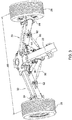
Fig. 2 is a plan view of a rear portion of the implement frame ofFig. 1 illustrating the wheels and swing arms in the transport position; -
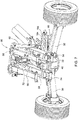
Fig. 3 is a perspective view of the rear portion of the implement frame shown inFig. 2 with the wheels and swing arms in the field use position; -
Fig. 4 is an exploded perspective view illustrating the attachment of the pivot frame to the carriage frame for rotation about a pivot; -
Fig. 5 is a perspective view of the implement frame ofFig. 1 with the lift assembly in the forwardly shifted position prior to rotation of the pivot frame. -
Fig. 6 is a cut away side view of the implement frame illustrating the shift assembly; -
Fig. 7 is a rear perspective view of the implement frame ofFig. 1 in the field use position; and -
Fig. 8 is a rear perspective view showing the implement frame ofFig. 1 with the tool bar in the field use position. - An
implement frame 20 is shown and described with reference to the figures.Implement frame 20 includes acarriage frame 22 having atongue 24 at one end for coupling the frame to a towing vehicle, such as a tractor, not shown. Various types oftongues 24 can be used depending on the user's preference or needs. Left andright wheels carriage frame 22 by left andright swing arms arrow 34. -
Implement frame 20 further includes apivot frame 40 mounted to thecarriage frame 22 for rotation about a generallyupright axis 42. Alift assembly 50 is in turn coupled to thepivot frame 40, and atool bar 60 is connected to thelift assembly 50. The implement frame is designed to enable movement of the tool bar between a transport position and a field use position. The transport position is shown inFig. 1 in which the length of thetool bar 60 is oriented longitudinally with respect to the carriage frame and the direction of forward travel. Thepivot frame 40 andlift assembly 50 are used to move the tool bar from the fore and aft extending transport position ofFig. 1 to a transversely extending use position. As will be described in detail below, thelift assembly 50 is coupled to the pivot frame through ashift assembly 70 that moves the lift assembly, and thereby the tool bar, radially relative to theaxis 42. Shifting of the tool bar more evenly centers the tool bar and the tools mounted thereon (not shown) relative to thecarriage frame 22 andwheels - With reference to
Figs. 2 and3 , the wheels andswing arms bars pivot joints 80. At the opposite ends, each arm is pivotally coupled to awheel hub bracket 84 bypivot joints 82. Wheel hubs, not shown, are mounted to thebrackets 84 and the wheels are mounted to the hubs in a conventional manner. The position of theswing arms hydraulic cylinders 86. Other types of actuators may be used if desired. Thecylinders 86 are coupled at their cap ends to the carriage frame and the rod ends are coupled to the swing arms. As shown inFig. 2 , the swing arms are rotated rearward relative to the carriage frame to a transport position in which thetrack width 88, measured as the distance between to center lines of the two wheels, is reduced for a narrower transport track width. Thebars 30A/30B and 32A/32B are configured as a parallel linkage to maintain the wheel hubs in a fixed attitude with the wheels aligned with theforward travel direction 34. - In
Fig. 3 , the rods of thecylinders 86 have been retracted to bring the swing arms forward, moving the wheels outward to a position of increasedtrack width 89. This wider track width position provides greater stability for the implement when the tool bar is in the field use position. In the field use position,struts 90 are coupled between thecarriage frame 22 and the swing arms to hold the swing arms in position without reliance on hydraulic pressure. Thestruts 90 are coupled to the swing arms byremovable pins 92. The struts may be in the form of turn buckles that are adjustable in length to enable the field use track width to be set based on the spacing of tools on the tool bar so that the wheels may track between tools. During transport, thestruts 90 are pivoted forwardly, along the side of the carriage frame, and held in brackets 94 (Fig. 1 ). - The pivotal coupling of the
pivot frame 40 to thecarriage frame 22 is shown inFig. 4 . Thepivot frame 40 includes apost 100 received insleeve 102 of the carriage frame with appropriate bearings and/or bushings (not shown) as needed to allow thepivot frame 40 to rotate about theaxis 42. An actuator, shown as ahydraulic cylinder 104, is mounted to abracket 106 on the carriage frame and to thepivot frame 40 atjoint 108, a distance from theaxis 42. Extension and retraction of the rod of cylinder rotates the pivot frame relative to the carriage frame. SeeFig. 5 . - With reference to
Figs. 5 and6 , the mounting of thelift assembly 50 to thepivot frame 40 via theshift assembly 70 is shown in detail. Thelift assembly 50 includes alift frame 52 to whichlower lift arms 54 andupper lift arms 56 are pivotally mounted. Theshift assembly 70 includes a pair ofshift arms 72 pivotally coupled at one end to thepivot frame 40 atjoints 74. An actuator in the form of ahydraulic cylinder 76 extends between thepivot frame 40 and one of theshift arms 72. Theshift arms 72, together with thepivot frame 40 andlift frame 52 form a parallel linkage to maintain thelift frame 52 in a fixed attitude while moving with the shift arms. In addition, theshift assembly 70 includes afollower 77 which is captured and slides within aslot 78 in the pivot frame to further stabilize thelift frame 52. - The
lift arms hydraulic cylinders 58, are coupled between the lift frame52 and thelower lift arms 54. Extension and retraction of the rods of thecylinders 58 raises and lowers the lift arms. The lift arms, thelift frame 52 and thetool bar 60 form a parallel linkage to keep the tool bar in a fixed attitude between positions. - The implement frame is shown in the field use position in
Figs. 7 and8 . The pivot frame is rotated to the position where the tool bar, not shown, extends transversely to the direction of travel. The shift assembly is in the rearward position and thelift arms swing arms - To transition from field use to transport, first, the lift arms are raised by extending the rod of
cylinders 58. Next, the shift arms are moved forward by extending the rod ofcylinder 76. This moves the tool bar forward. Following the shift, thepivot frame 40 is rotated approximately ninety degrees to rotate the tool bar from a transversely extending orientation to a longitudinally extending orientation. Lastly, thestruts 90 are decoupled from theswing arms cylinders 86. This decreases the track width for narrower transport. Transitioning back to the field use position is accomplished by reversing the above steps. The entire operation of moving from field use to transport and back again, is accomplished by automated means; the use of actuators, such as hydraulic cylinders, except for the coupling and decoupling of thestruts 90. Throughout the entire process, the tool bar is maintained in a fixed attitude such that there is no spillage or leakage of seed or chemicals from planter or application tools mounted to the tool bar. The result is an implement frame that can be quickly and easily transitioned between field use and transport positions. As those knowledgeable in implement frames will appreciate, the variable track width feature can be used with other types of lift and pivot mechanisms or other folding frame mechanisms to reduce transport width. - Having described the preferred embodiment, it will become apparent that various modifications can be made without departing from the scope of the invention as defined in the accompanying claims.
Claims (15)
- An implement frame assembly (20) comprising:a carriage frame (22) having a tongue for coupling to a hitch of a towing vehicle and wheels supporting the carriage frame for movement over a ground surface;a pivot frame (20) mounted to the carriage frame for rotation about an axis approximately ninety degrees;a lift assembly (50) coupled to the pivot frame by a shift assembly, the shift assembly moving the lift assembly radially relative to the axis; anda tool bar (60) connected to the lift assembly for movement between a lower ground engaging position and a raised position.
- The implement frame of claim 1 wherein the lift assembly includes a lift frame (52) mounted to the pivot frame (40) by a shift arm (72) and an actuator (76) coupled to the pivot frame and the shift arm for moving the shift arm about a pivot.
- The implement frame of claim 2 further comprising a guide slot (78) in the pivot frame and a follower (77) mounted to the lift frame of the lift assembly for guided movement of the lift assembly as the lift assembly is shifted upon operation of the actuator.
- The implement frame of claim 2 comprising a pair of shift arms (72) whereby the shift arms, the pivot frame and the lift frame of the lift assembly form a parallel linkage.
- The implement frame of claim 4 further comprising a guide slot (78) in the pivot frame and a follower (77) mounted to the lift frame of the lift assembly for guided movement of the lift assembly as the lift assembly is shifted upon operation of the actuator.
- The implement frame of claim 1 wherein the lift assembly includes a lift frame and upper and lower lift arms (54, 56) pivotally coupled to the lift frame and the toolbar whereby the lift frame, the tool bar and the upper and lower lift arms form a parallel linkage.
- The implement frame of claim 6 further comprising a pair of upper and lower lift arms (54, 56) coupled to the lift frame and the toolbar.
- The implement frame of any preceding claim wherein the wheels are mounted to the carriage frame by a pair of swing arms pivotally coupled to the carriage frame to selectively vary the track width between a wider field track width and a narrower transport track width by movement of the swing arms.
- The implement frame of claim 8 further comprising an actuator extending between the carriage frame and each swing arm to move the swing arms relative to the carriage frame.
- An implement frame assembly comprising:a carriage frame (22) having a tongue for coupling to a hitch of a towing vehicle and a pair of wheels for supporting the carriage frame for movement over a ground surface, the wheels (26, 28) being spaced laterally from one another by a track width and wherein the wheels are mounted to the carriage frame by a pair of swing arms (30, 32) pivotally coupled to the carriage frame to selectively vary the track width between a wider field track width and a narrower transport track width by movement of the swing arms;a pivot frame (40) mounted to the carriage frame for rotation about an axis;a lift assembly (50) carried by the pivot framea tool bar (60) connected to the lift assembly for movement between a lower ground engaging position and a raised position.
- The implement frame of claim 10 further comprising an actuator (76) extending between the carriage frame and each swing arm to move the swing arms relative to the carriage frame.
- The implement frame of claim 10 further comprising a strut (90) extending between the carriage frame and each swing arm to hold the swing arms in the field track width position, the struts (90) being releasably coupled to the swing arms to remove the struts from the swing arms to move the swing arms to the transport track width position.
- A method of transitioning an implement frame between a field use position and a road transport position, the implement frame having a carriage frame with a tongue for coupling to a hitch of a towing vehicle, wheels coupled to the carriage frame for supporting the implement for movement over a ground surface, and a toolbar extending transversely relative to the direction of travel in the field use position, the method comprising:raising the tool bar from a ground engaging position;shifting the tool bar forward relative to the carriage frame; andpivoting the toolbar approximately ninety degrees to a fore and aft extending position.
- The method of claim 16 further comprising moving the wheels from a field use position to a transport position.
- The method of claim 17 wherein the track width of the wheels is narrower in the transport position than in the field use position.
Applications Claiming Priority (1)
| Application Number | Priority Date | Filing Date | Title |
|---|---|---|---|
| US15/184,238 US10172276B2 (en) | 2016-06-16 | 2016-06-16 | Implement frame convertible between field and transport positions |
Publications (2)
| Publication Number | Publication Date |
|---|---|
| EP3257347A1 true EP3257347A1 (en) | 2017-12-20 |
| EP3257347B1 EP3257347B1 (en) | 2023-05-24 |
Family
ID=58873694
Family Applications (1)
| Application Number | Title | Priority Date | Filing Date |
|---|---|---|---|
| EP17173519.4A Active EP3257347B1 (en) | 2016-06-16 | 2017-05-30 | Implement frame convertible between field and transport positions |
Country Status (4)
| Country | Link |
|---|---|
| US (2) | US10172276B2 (en) |
| EP (1) | EP3257347B1 (en) |
| AR (1) | AR108486A1 (en) |
| BR (1) | BR102017010055B1 (en) |
Cited By (2)
| Publication number | Priority date | Publication date | Assignee | Title |
|---|---|---|---|---|
| EP3516939A1 (en) * | 2018-01-30 | 2019-07-31 | AGCO Feucht GmbH | Towed agricultural implement |
| US11297756B2 (en) | 2018-05-21 | 2022-04-12 | Charles H. Martin | Agricultural device having a rotatable frame portion |
Families Citing this family (6)
| Publication number | Priority date | Publication date | Assignee | Title |
|---|---|---|---|---|
| US10172276B2 (en) * | 2016-06-16 | 2019-01-08 | Deer & Company | Implement frame convertible between field and transport positions |
| EP3669624B1 (en) * | 2018-12-17 | 2023-09-20 | CNH Industrial Belgium NV | A combine header equipped with an automated header transport system and header steering mechanism |
| EP3669625B1 (en) * | 2018-12-17 | 2023-08-16 | CNH Industrial Belgium NV | A combine header equipped with an automated header transport system and drawbar |
| EP3669626B1 (en) * | 2018-12-17 | 2021-08-18 | CNH Industrial Belgium NV | A combine header equipped with an automated header transport system |
| TWI806007B (en) * | 2021-02-25 | 2023-06-21 | 温志仁 | Revitalize the facility structure of farmland |
| EP4691218A1 (en) * | 2024-08-07 | 2026-02-11 | Agco Corporation | Agricultural implements and related methods |
Citations (4)
| Publication number | Priority date | Publication date | Assignee | Title |
|---|---|---|---|---|
| US6238170B1 (en) * | 2000-07-12 | 2001-05-29 | Agco Corporation | Agricultural implement trailer |
| US6561535B1 (en) * | 2002-01-31 | 2003-05-13 | Case, Llc | Hose control for planter apparatus |
| EP1366650A1 (en) * | 2002-05-29 | 2003-12-03 | Kuhn S.A. | Agricultural implement comprising a transporting device |
| EP2656712A1 (en) * | 2012-04-26 | 2013-10-30 | Macdon Industries Ltd | Pull-type crop harvesting machine transport system actuated at a predetermined angle of the hitch |
Family Cites Families (21)
| Publication number | Priority date | Publication date | Assignee | Title |
|---|---|---|---|---|
| US2706881A (en) * | 1950-07-15 | 1955-04-26 | Georgia S Cusack | Race track scarifier |
| US3172480A (en) * | 1961-10-19 | 1965-03-09 | Thomas F Bemis | Three-point offset universal coupling system |
| EP0048777A1 (en) * | 1979-04-06 | 1982-04-07 | Howard James Richter | Tractor |
| US4721168A (en) * | 1985-09-23 | 1988-01-26 | Kinzenbaw Jon E | Agricultural implement with raisable lift frame rotatable about vertical axis |
| US6213034B1 (en) * | 1998-08-27 | 2001-04-10 | Case Corporation | Planter apparatus and method |
| US6321852B1 (en) * | 2000-01-26 | 2001-11-27 | Deere & Company | Agricultural implement frame having a transport configuration and a working configuration |
| USD469782S1 (en) * | 2001-11-29 | 2003-02-04 | Case Corporation | Pivot transport planter apparatus |
| US7604068B1 (en) * | 2005-02-24 | 2009-10-20 | Arlyn E. Friesen | Forwardly folding tool bar |
| US7849933B2 (en) * | 2007-10-19 | 2010-12-14 | Kuhn North America, Inc. | Bifold transport lock |
| US7849932B2 (en) * | 2008-05-01 | 2010-12-14 | Cnh Canada, Ltd. | Steering and elevating wheel system for agricultural implement |
| US7900711B2 (en) | 2008-07-08 | 2011-03-08 | Kinze Manufacturing, Inc. | Agricultural planter |
| US8267186B2 (en) * | 2009-06-11 | 2012-09-18 | Forage Innovations B.V. | Folding tool bar method and apparatus for use with agricultural implements |
| US8657025B2 (en) * | 2009-06-11 | 2014-02-25 | Forage Innovations B.V. | Folding frame for an agricultural implement |
| US9072214B2 (en) * | 2009-10-29 | 2015-07-07 | Cnh Industrial America Llc | Steerable agricultural implement with adaptable wheel spacing |
| US8342255B2 (en) * | 2009-10-29 | 2013-01-01 | Cnh America Llc | Steerable agricultural implement with equalized steering effort |
| NL1037561C2 (en) * | 2009-12-16 | 2011-06-20 | Lely Patent Nv | DEVICE INTENDED FOR AGRICULTURE. |
| US8534982B2 (en) * | 2011-01-31 | 2013-09-17 | Bestway, Inc. | Rotating lift system and method |
| US9533612B2 (en) * | 2011-01-31 | 2017-01-03 | Bestway, Inc. | Rotating lift system and method |
| US10188022B2 (en) * | 2011-01-31 | 2019-01-29 | Bestway, Inc. | Rotating lift system and method |
| US9220188B2 (en) * | 2013-08-19 | 2015-12-29 | Forage Innovations B.V. | Individually articulating automatic transport locks for folding implements |
| US10172276B2 (en) * | 2016-06-16 | 2019-01-08 | Deer & Company | Implement frame convertible between field and transport positions |
-
2016
- 2016-06-16 US US15/184,238 patent/US10172276B2/en active Active
-
2017
- 2017-05-12 BR BR102017010055-3A patent/BR102017010055B1/en active IP Right Grant
- 2017-05-16 AR ARP170101297A patent/AR108486A1/en active IP Right Grant
- 2017-05-30 EP EP17173519.4A patent/EP3257347B1/en active Active
-
2018
- 2018-12-17 US US16/222,600 patent/US10980165B2/en active Active
Patent Citations (4)
| Publication number | Priority date | Publication date | Assignee | Title |
|---|---|---|---|---|
| US6238170B1 (en) * | 2000-07-12 | 2001-05-29 | Agco Corporation | Agricultural implement trailer |
| US6561535B1 (en) * | 2002-01-31 | 2003-05-13 | Case, Llc | Hose control for planter apparatus |
| EP1366650A1 (en) * | 2002-05-29 | 2003-12-03 | Kuhn S.A. | Agricultural implement comprising a transporting device |
| EP2656712A1 (en) * | 2012-04-26 | 2013-10-30 | Macdon Industries Ltd | Pull-type crop harvesting machine transport system actuated at a predetermined angle of the hitch |
Cited By (2)
| Publication number | Priority date | Publication date | Assignee | Title |
|---|---|---|---|---|
| EP3516939A1 (en) * | 2018-01-30 | 2019-07-31 | AGCO Feucht GmbH | Towed agricultural implement |
| US11297756B2 (en) | 2018-05-21 | 2022-04-12 | Charles H. Martin | Agricultural device having a rotatable frame portion |
Also Published As
| Publication number | Publication date |
|---|---|
| BR102017010055A2 (en) | 2017-12-26 |
| US20170359942A1 (en) | 2017-12-21 |
| BR102017010055B1 (en) | 2022-08-09 |
| US10172276B2 (en) | 2019-01-08 |
| AR108486A1 (en) | 2018-08-22 |
| US10980165B2 (en) | 2021-04-20 |
| EP3257347B1 (en) | 2023-05-24 |
| US20190183032A1 (en) | 2019-06-20 |
Similar Documents
| Publication | Publication Date | Title |
|---|---|---|
| US10980165B2 (en) | Implement frame convertible between field and transport positions | |
| US8127861B2 (en) | Front folding agricultural implement frame with rearwardly telescoping tongue | |
| US6408950B1 (en) | Foldable implement frame and hitch | |
| US11751498B2 (en) | Toolbar system for an agricultural implement | |
| US9198342B2 (en) | Rear folding toolbar implement | |
| US4945997A (en) | Folding agricultural implement | |
| US4723787A (en) | Implement transport hitch | |
| US8770309B2 (en) | Wide swath folding tool bar assembly | |
| US20040050563A1 (en) | Foldable implement frame and hitch | |
| US8418777B1 (en) | Agricultural folding scraper blade | |
| US9763376B2 (en) | Forward rotating transport axle | |
| US4214637A (en) | Elevation altering structure for agricultural implements | |
| US4088346A (en) | Foldable implement | |
| US10561053B1 (en) | Frame assembly and actuator arrangement for agricultural imglements | |
| US4117892A (en) | Agricultural folding tool bar with rigid cross frame | |
| US4211288A (en) | Raisable implement frame with operably connected wheel and draft frames | |
| US11582894B2 (en) | Frame and leveling assembly for agricultural implement | |
| US9198340B2 (en) | Agricultural implement marker foldable about compound angle | |
| US20220256762A1 (en) | Pivoting and folding toolbar for fertilizer implement | |
| SE535579C2 (en) | Felling device at an agricultural machine | |
| WO2026022275A1 (en) | Agricultural implements and methods of folding agricultural implements | |
| US20180084707A1 (en) | Agricultural implement |
Legal Events
| Date | Code | Title | Description |
|---|---|---|---|
| PUAI | Public reference made under article 153(3) epc to a published international application that has entered the european phase |
Free format text: ORIGINAL CODE: 0009012 |
|
| STAA | Information on the status of an ep patent application or granted ep patent |
Free format text: STATUS: THE APPLICATION HAS BEEN PUBLISHED |
|
| AK | Designated contracting states |
Kind code of ref document: A1 Designated state(s): AL AT BE BG CH CY CZ DE DK EE ES FI FR GB GR HR HU IE IS IT LI LT LU LV MC MK MT NL NO PL PT RO RS SE SI SK SM TR |
|
| AX | Request for extension of the european patent |
Extension state: BA ME |
|
| STAA | Information on the status of an ep patent application or granted ep patent |
Free format text: STATUS: REQUEST FOR EXAMINATION WAS MADE |
|
| 17P | Request for examination filed |
Effective date: 20180620 |
|
| RBV | Designated contracting states (corrected) |
Designated state(s): AL AT BE BG CH CY CZ DE DK EE ES FI FR GB GR HR HU IE IS IT LI LT LU LV MC MK MT NL NO PL PT RO RS SE SI SK SM TR |
|
| STAA | Information on the status of an ep patent application or granted ep patent |
Free format text: STATUS: EXAMINATION IS IN PROGRESS |
|
| 17Q | First examination report despatched |
Effective date: 20200129 |
|
| GRAP | Despatch of communication of intention to grant a patent |
Free format text: ORIGINAL CODE: EPIDOSNIGR1 |
|
| STAA | Information on the status of an ep patent application or granted ep patent |
Free format text: STATUS: GRANT OF PATENT IS INTENDED |
|
| INTG | Intention to grant announced |
Effective date: 20220518 |
|
| GRAJ | Information related to disapproval of communication of intention to grant by the applicant or resumption of examination proceedings by the epo deleted |
Free format text: ORIGINAL CODE: EPIDOSDIGR1 |
|
| STAA | Information on the status of an ep patent application or granted ep patent |
Free format text: STATUS: EXAMINATION IS IN PROGRESS |
|
| INTC | Intention to grant announced (deleted) | ||
| GRAP | Despatch of communication of intention to grant a patent |
Free format text: ORIGINAL CODE: EPIDOSNIGR1 |
|
| STAA | Information on the status of an ep patent application or granted ep patent |
Free format text: STATUS: GRANT OF PATENT IS INTENDED |
|
| INTG | Intention to grant announced |
Effective date: 20221215 |
|
| GRAS | Grant fee paid |
Free format text: ORIGINAL CODE: EPIDOSNIGR3 |
|
| GRAA | (expected) grant |
Free format text: ORIGINAL CODE: 0009210 |
|
| STAA | Information on the status of an ep patent application or granted ep patent |
Free format text: STATUS: THE PATENT HAS BEEN GRANTED |
|
| AK | Designated contracting states |
Kind code of ref document: B1 Designated state(s): AL AT BE BG CH CY CZ DE DK EE ES FI FR GB GR HR HU IE IS IT LI LT LU LV MC MK MT NL NO PL PT RO RS SE SI SK SM TR |
|
| REG | Reference to a national code |
Ref country code: GB Ref legal event code: FG4D |
|
| REG | Reference to a national code |
Ref country code: CH Ref legal event code: EP |
|
| REG | Reference to a national code |
Ref country code: DE Ref legal event code: R096 Ref document number: 602017068947 Country of ref document: DE |
|
| REG | Reference to a national code |
Ref country code: AT Ref legal event code: REF Ref document number: 1568955 Country of ref document: AT Kind code of ref document: T Effective date: 20230615 |
|
| REG | Reference to a national code |
Ref country code: IE Ref legal event code: FG4D |
|
| REG | Reference to a national code |
Ref country code: LT Ref legal event code: MG9D |
|
| REG | Reference to a national code |
Ref country code: NL Ref legal event code: MP Effective date: 20230524 |
|
| REG | Reference to a national code |
Ref country code: AT Ref legal event code: MK05 Ref document number: 1568955 Country of ref document: AT Kind code of ref document: T Effective date: 20230524 |
|
| PG25 | Lapsed in a contracting state [announced via postgrant information from national office to epo] |
Ref country code: SE Free format text: LAPSE BECAUSE OF FAILURE TO SUBMIT A TRANSLATION OF THE DESCRIPTION OR TO PAY THE FEE WITHIN THE PRESCRIBED TIME-LIMIT Effective date: 20230524 Ref country code: PT Free format text: LAPSE BECAUSE OF FAILURE TO SUBMIT A TRANSLATION OF THE DESCRIPTION OR TO PAY THE FEE WITHIN THE PRESCRIBED TIME-LIMIT Effective date: 20230925 Ref country code: NO Free format text: LAPSE BECAUSE OF FAILURE TO SUBMIT A TRANSLATION OF THE DESCRIPTION OR TO PAY THE FEE WITHIN THE PRESCRIBED TIME-LIMIT Effective date: 20230824 Ref country code: NL Free format text: LAPSE BECAUSE OF FAILURE TO SUBMIT A TRANSLATION OF THE DESCRIPTION OR TO PAY THE FEE WITHIN THE PRESCRIBED TIME-LIMIT Effective date: 20230524 Ref country code: ES Free format text: LAPSE BECAUSE OF FAILURE TO SUBMIT A TRANSLATION OF THE DESCRIPTION OR TO PAY THE FEE WITHIN THE PRESCRIBED TIME-LIMIT Effective date: 20230524 Ref country code: AT Free format text: LAPSE BECAUSE OF FAILURE TO SUBMIT A TRANSLATION OF THE DESCRIPTION OR TO PAY THE FEE WITHIN THE PRESCRIBED TIME-LIMIT Effective date: 20230524 |
|
| PG25 | Lapsed in a contracting state [announced via postgrant information from national office to epo] |
Ref country code: RS Free format text: LAPSE BECAUSE OF FAILURE TO SUBMIT A TRANSLATION OF THE DESCRIPTION OR TO PAY THE FEE WITHIN THE PRESCRIBED TIME-LIMIT Effective date: 20230524 Ref country code: PL Free format text: LAPSE BECAUSE OF FAILURE TO SUBMIT A TRANSLATION OF THE DESCRIPTION OR TO PAY THE FEE WITHIN THE PRESCRIBED TIME-LIMIT Effective date: 20230524 Ref country code: LV Free format text: LAPSE BECAUSE OF FAILURE TO SUBMIT A TRANSLATION OF THE DESCRIPTION OR TO PAY THE FEE WITHIN THE PRESCRIBED TIME-LIMIT Effective date: 20230524 Ref country code: LT Free format text: LAPSE BECAUSE OF FAILURE TO SUBMIT A TRANSLATION OF THE DESCRIPTION OR TO PAY THE FEE WITHIN THE PRESCRIBED TIME-LIMIT Effective date: 20230524 Ref country code: IS Free format text: LAPSE BECAUSE OF FAILURE TO SUBMIT A TRANSLATION OF THE DESCRIPTION OR TO PAY THE FEE WITHIN THE PRESCRIBED TIME-LIMIT Effective date: 20230924 Ref country code: HR Free format text: LAPSE BECAUSE OF FAILURE TO SUBMIT A TRANSLATION OF THE DESCRIPTION OR TO PAY THE FEE WITHIN THE PRESCRIBED TIME-LIMIT Effective date: 20230524 Ref country code: GR Free format text: LAPSE BECAUSE OF FAILURE TO SUBMIT A TRANSLATION OF THE DESCRIPTION OR TO PAY THE FEE WITHIN THE PRESCRIBED TIME-LIMIT Effective date: 20230825 |
|
| PG25 | Lapsed in a contracting state [announced via postgrant information from national office to epo] |
Ref country code: FI Free format text: LAPSE BECAUSE OF FAILURE TO SUBMIT A TRANSLATION OF THE DESCRIPTION OR TO PAY THE FEE WITHIN THE PRESCRIBED TIME-LIMIT Effective date: 20230524 |
|
| REG | Reference to a national code |
Ref country code: CH Ref legal event code: PL |
|
| PG25 | Lapsed in a contracting state [announced via postgrant information from national office to epo] |
Ref country code: SK Free format text: LAPSE BECAUSE OF FAILURE TO SUBMIT A TRANSLATION OF THE DESCRIPTION OR TO PAY THE FEE WITHIN THE PRESCRIBED TIME-LIMIT Effective date: 20230524 |
|
| REG | Reference to a national code |
Ref country code: BE Ref legal event code: MM Effective date: 20230531 |
|
| PG25 | Lapsed in a contracting state [announced via postgrant information from national office to epo] |
Ref country code: SM Free format text: LAPSE BECAUSE OF FAILURE TO SUBMIT A TRANSLATION OF THE DESCRIPTION OR TO PAY THE FEE WITHIN THE PRESCRIBED TIME-LIMIT Effective date: 20230524 Ref country code: SK Free format text: LAPSE BECAUSE OF FAILURE TO SUBMIT A TRANSLATION OF THE DESCRIPTION OR TO PAY THE FEE WITHIN THE PRESCRIBED TIME-LIMIT Effective date: 20230524 Ref country code: RO Free format text: LAPSE BECAUSE OF FAILURE TO SUBMIT A TRANSLATION OF THE DESCRIPTION OR TO PAY THE FEE WITHIN THE PRESCRIBED TIME-LIMIT Effective date: 20230524 Ref country code: LU Free format text: LAPSE BECAUSE OF NON-PAYMENT OF DUE FEES Effective date: 20230530 Ref country code: LI Free format text: LAPSE BECAUSE OF NON-PAYMENT OF DUE FEES Effective date: 20230531 Ref country code: EE Free format text: LAPSE BECAUSE OF FAILURE TO SUBMIT A TRANSLATION OF THE DESCRIPTION OR TO PAY THE FEE WITHIN THE PRESCRIBED TIME-LIMIT Effective date: 20230524 Ref country code: DK Free format text: LAPSE BECAUSE OF FAILURE TO SUBMIT A TRANSLATION OF THE DESCRIPTION OR TO PAY THE FEE WITHIN THE PRESCRIBED TIME-LIMIT Effective date: 20230524 Ref country code: CZ Free format text: LAPSE BECAUSE OF FAILURE TO SUBMIT A TRANSLATION OF THE DESCRIPTION OR TO PAY THE FEE WITHIN THE PRESCRIBED TIME-LIMIT Effective date: 20230524 Ref country code: CH Free format text: LAPSE BECAUSE OF NON-PAYMENT OF DUE FEES Effective date: 20230531 |
|
| REG | Reference to a national code |
Ref country code: DE Ref legal event code: R097 Ref document number: 602017068947 Country of ref document: DE |
|
| PG25 | Lapsed in a contracting state [announced via postgrant information from national office to epo] |
Ref country code: MC Free format text: LAPSE BECAUSE OF FAILURE TO SUBMIT A TRANSLATION OF THE DESCRIPTION OR TO PAY THE FEE WITHIN THE PRESCRIBED TIME-LIMIT Effective date: 20230524 |
|
| REG | Reference to a national code |
Ref country code: IE Ref legal event code: MM4A |
|
| PG25 | Lapsed in a contracting state [announced via postgrant information from national office to epo] |
Ref country code: MC Free format text: LAPSE BECAUSE OF FAILURE TO SUBMIT A TRANSLATION OF THE DESCRIPTION OR TO PAY THE FEE WITHIN THE PRESCRIBED TIME-LIMIT Effective date: 20230524 |
|
| PLBE | No opposition filed within time limit |
Free format text: ORIGINAL CODE: 0009261 |
|
| STAA | Information on the status of an ep patent application or granted ep patent |
Free format text: STATUS: NO OPPOSITION FILED WITHIN TIME LIMIT |
|
| PG25 | Lapsed in a contracting state [announced via postgrant information from national office to epo] |
Ref country code: IE Free format text: LAPSE BECAUSE OF NON-PAYMENT OF DUE FEES Effective date: 20230530 |
|
| GBPC | Gb: european patent ceased through non-payment of renewal fee |
Effective date: 20230824 |
|
| PG25 | Lapsed in a contracting state [announced via postgrant information from national office to epo] |
Ref country code: IE Free format text: LAPSE BECAUSE OF NON-PAYMENT OF DUE FEES Effective date: 20230530 |
|
| 26N | No opposition filed |
Effective date: 20240227 |
|
| PG25 | Lapsed in a contracting state [announced via postgrant information from national office to epo] |
Ref country code: SI Free format text: LAPSE BECAUSE OF FAILURE TO SUBMIT A TRANSLATION OF THE DESCRIPTION OR TO PAY THE FEE WITHIN THE PRESCRIBED TIME-LIMIT Effective date: 20230524 |
|
| PG25 | Lapsed in a contracting state [announced via postgrant information from national office to epo] |
Ref country code: SI Free format text: LAPSE BECAUSE OF FAILURE TO SUBMIT A TRANSLATION OF THE DESCRIPTION OR TO PAY THE FEE WITHIN THE PRESCRIBED TIME-LIMIT Effective date: 20230524 Ref country code: IT Free format text: LAPSE BECAUSE OF FAILURE TO SUBMIT A TRANSLATION OF THE DESCRIPTION OR TO PAY THE FEE WITHIN THE PRESCRIBED TIME-LIMIT Effective date: 20230524 Ref country code: BE Free format text: LAPSE BECAUSE OF NON-PAYMENT OF DUE FEES Effective date: 20230531 |
|
| PG25 | Lapsed in a contracting state [announced via postgrant information from national office to epo] |
Ref country code: GB Free format text: LAPSE BECAUSE OF NON-PAYMENT OF DUE FEES Effective date: 20230824 |
|
| PG25 | Lapsed in a contracting state [announced via postgrant information from national office to epo] |
Ref country code: GB Free format text: LAPSE BECAUSE OF NON-PAYMENT OF DUE FEES Effective date: 20230824 |
|
| PG25 | Lapsed in a contracting state [announced via postgrant information from national office to epo] |
Ref country code: BG Free format text: LAPSE BECAUSE OF FAILURE TO SUBMIT A TRANSLATION OF THE DESCRIPTION OR TO PAY THE FEE WITHIN THE PRESCRIBED TIME-LIMIT Effective date: 20230524 |
|
| PG25 | Lapsed in a contracting state [announced via postgrant information from national office to epo] |
Ref country code: BG Free format text: LAPSE BECAUSE OF FAILURE TO SUBMIT A TRANSLATION OF THE DESCRIPTION OR TO PAY THE FEE WITHIN THE PRESCRIBED TIME-LIMIT Effective date: 20230524 |
|
| PGFP | Annual fee paid to national office [announced via postgrant information from national office to epo] |
Ref country code: DE Payment date: 20250423 Year of fee payment: 9 |
|
| PGFP | Annual fee paid to national office [announced via postgrant information from national office to epo] |
Ref country code: FR Payment date: 20250526 Year of fee payment: 9 |
|
| PG25 | Lapsed in a contracting state [announced via postgrant information from national office to epo] |
Ref country code: CY Free format text: LAPSE BECAUSE OF FAILURE TO SUBMIT A TRANSLATION OF THE DESCRIPTION OR TO PAY THE FEE WITHIN THE PRESCRIBED TIME-LIMIT; INVALID AB INITIO Effective date: 20170530 |
|
| PG25 | Lapsed in a contracting state [announced via postgrant information from national office to epo] |
Ref country code: HU Free format text: LAPSE BECAUSE OF FAILURE TO SUBMIT A TRANSLATION OF THE DESCRIPTION OR TO PAY THE FEE WITHIN THE PRESCRIBED TIME-LIMIT; INVALID AB INITIO Effective date: 20170530 |
|
| PG25 | Lapsed in a contracting state [announced via postgrant information from national office to epo] |
Ref country code: TR Free format text: LAPSE BECAUSE OF FAILURE TO SUBMIT A TRANSLATION OF THE DESCRIPTION OR TO PAY THE FEE WITHIN THE PRESCRIBED TIME-LIMIT Effective date: 20230524 |