EP3256823B1 - Oil pan with integrated capacitive sensor for measuring oil level - Google Patents
Oil pan with integrated capacitive sensor for measuring oil level Download PDFInfo
- Publication number
- EP3256823B1 EP3256823B1 EP16708530.7A EP16708530A EP3256823B1 EP 3256823 B1 EP3256823 B1 EP 3256823B1 EP 16708530 A EP16708530 A EP 16708530A EP 3256823 B1 EP3256823 B1 EP 3256823B1
- Authority
- EP
- European Patent Office
- Prior art keywords
- oil
- oil pan
- capacitance
- oil level
- sensor
- Prior art date
- Legal status (The legal status is an assumption and is not a legal conclusion. Google has not performed a legal analysis and makes no representation as to the accuracy of the status listed.)
- Active
Links
Images



Classifications
-
- F—MECHANICAL ENGINEERING; LIGHTING; HEATING; WEAPONS; BLASTING
- F01—MACHINES OR ENGINES IN GENERAL; ENGINE PLANTS IN GENERAL; STEAM ENGINES
- F01M—LUBRICATING OF MACHINES OR ENGINES IN GENERAL; LUBRICATING INTERNAL COMBUSTION ENGINES; CRANKCASE VENTILATING
- F01M11/00—Component parts, details or accessories, not provided for in, or of interest apart from, groups F01M1/00 - F01M9/00
- F01M11/0004—Oilsumps
-
- F—MECHANICAL ENGINEERING; LIGHTING; HEATING; WEAPONS; BLASTING
- F01—MACHINES OR ENGINES IN GENERAL; ENGINE PLANTS IN GENERAL; STEAM ENGINES
- F01M—LUBRICATING OF MACHINES OR ENGINES IN GENERAL; LUBRICATING INTERNAL COMBUSTION ENGINES; CRANKCASE VENTILATING
- F01M11/00—Component parts, details or accessories, not provided for in, or of interest apart from, groups F01M1/00 - F01M9/00
- F01M11/10—Indicating devices; Other safety devices
- F01M11/12—Indicating devices; Other safety devices concerning lubricant level
-
- G—PHYSICS
- G01—MEASURING; TESTING
- G01F—MEASURING VOLUME, VOLUME FLOW, MASS FLOW OR LIQUID LEVEL; METERING BY VOLUME
- G01F23/00—Indicating or measuring liquid level or level of fluent solid material, e.g. indicating in terms of volume or indicating by means of an alarm
- G01F23/22—Indicating or measuring liquid level or level of fluent solid material, e.g. indicating in terms of volume or indicating by means of an alarm by measuring physical variables, other than linear dimensions, pressure or weight, dependent on the level to be measured, e.g. by difference of heat transfer of steam or water
- G01F23/26—Indicating or measuring liquid level or level of fluent solid material, e.g. indicating in terms of volume or indicating by means of an alarm by measuring physical variables, other than linear dimensions, pressure or weight, dependent on the level to be measured, e.g. by difference of heat transfer of steam or water by measuring variations of capacity or inductance of capacitors or inductors arising from the presence of liquid or fluent solid material in the electric or electromagnetic fields
- G01F23/263—Indicating or measuring liquid level or level of fluent solid material, e.g. indicating in terms of volume or indicating by means of an alarm by measuring physical variables, other than linear dimensions, pressure or weight, dependent on the level to be measured, e.g. by difference of heat transfer of steam or water by measuring variations of capacity or inductance of capacitors or inductors arising from the presence of liquid or fluent solid material in the electric or electromagnetic fields by measuring variations in capacitance of capacitors
- G01F23/265—Indicating or measuring liquid level or level of fluent solid material, e.g. indicating in terms of volume or indicating by means of an alarm by measuring physical variables, other than linear dimensions, pressure or weight, dependent on the level to be measured, e.g. by difference of heat transfer of steam or water by measuring variations of capacity or inductance of capacitors or inductors arising from the presence of liquid or fluent solid material in the electric or electromagnetic fields by measuring variations in capacitance of capacitors for discrete levels
-
- G—PHYSICS
- G01—MEASURING; TESTING
- G01F—MEASURING VOLUME, VOLUME FLOW, MASS FLOW OR LIQUID LEVEL; METERING BY VOLUME
- G01F23/00—Indicating or measuring liquid level or level of fluent solid material, e.g. indicating in terms of volume or indicating by means of an alarm
- G01F23/22—Indicating or measuring liquid level or level of fluent solid material, e.g. indicating in terms of volume or indicating by means of an alarm by measuring physical variables, other than linear dimensions, pressure or weight, dependent on the level to be measured, e.g. by difference of heat transfer of steam or water
- G01F23/26—Indicating or measuring liquid level or level of fluent solid material, e.g. indicating in terms of volume or indicating by means of an alarm by measuring physical variables, other than linear dimensions, pressure or weight, dependent on the level to be measured, e.g. by difference of heat transfer of steam or water by measuring variations of capacity or inductance of capacitors or inductors arising from the presence of liquid or fluent solid material in the electric or electromagnetic fields
- G01F23/263—Indicating or measuring liquid level or level of fluent solid material, e.g. indicating in terms of volume or indicating by means of an alarm by measuring physical variables, other than linear dimensions, pressure or weight, dependent on the level to be measured, e.g. by difference of heat transfer of steam or water by measuring variations of capacity or inductance of capacitors or inductors arising from the presence of liquid or fluent solid material in the electric or electromagnetic fields by measuring variations in capacitance of capacitors
- G01F23/268—Indicating or measuring liquid level or level of fluent solid material, e.g. indicating in terms of volume or indicating by means of an alarm by measuring physical variables, other than linear dimensions, pressure or weight, dependent on the level to be measured, e.g. by difference of heat transfer of steam or water by measuring variations of capacity or inductance of capacitors or inductors arising from the presence of liquid or fluent solid material in the electric or electromagnetic fields by measuring variations in capacitance of capacitors mounting arrangements of probes
-
- G—PHYSICS
- G07—CHECKING-DEVICES
- G07C—TIME OR ATTENDANCE REGISTERS; REGISTERING OR INDICATING THE WORKING OF MACHINES; GENERATING RANDOM NUMBERS; VOTING OR LOTTERY APPARATUS; ARRANGEMENTS, SYSTEMS OR APPARATUS FOR CHECKING NOT PROVIDED FOR ELSEWHERE
- G07C5/00—Registering or indicating the working of vehicles
- G07C5/02—Registering or indicating driving, working, idle, or waiting time only
Definitions
- the present disclosure relates to motor vehicle oil pans, and in particular, to motor vehicle oil pans with an integrated capacitive sensor for measuring oil level.
- Oil plays an important role in motor vehicles, providing lubrication, which may reduce wear and tear on components during operation of the motor vehicles.
- the oil reduces heat caused by friction when the components rub against one another during operation.
- the oil is typically stored in an oil pan within a body of the motor vehicle. As the oil becomes depleted during operation, the oil's ability to perform effectively is degraded.
- the oil level in the pan is monitored periodically.
- Conventional methods and systems for monitoring the oil in the oil pan include a removable dipstick and manually monitoring the oil level by removing the dipstick and observing the oil on the dipstick.
- EP1722203A2 discloses a measuring system having several sensor surfaces for arrangement at the wall of a container, and an evaluation unit for determining the level of the container from measuring signals of individual sensor surfaces.
- the claimed invention provides an oil pan according to claim 1.
- Embodiments provide an oil level measuring system according to claim 9.
- Embodiments provide a motor vehicle according to claim 13.
- Embodiments include methods and systems that measure oil levels of oil containers, such as oil pans, in different types of motorized vehicles, such as automobiles (cars), trucks, buses, motorcycles, watercrafts (e.g., ships and boats) and aircrafts.
- motorized vehicles such as automobiles (cars), trucks, buses, motorcycles, watercrafts (e.g., ships and boats) and aircrafts.
- embodiments described herein include methods and systems that measure oil levels of oil containers in an automobile 100.
- FIG. 1 is a system diagram of an exemplary oil level measurement system 100.
- the exemplary oil level measurement system 100 includes an oil pan 102 with three or more sensors 104.
- the oil level measurement system may include a power source, such as battery 106 shown in FIG. 1 .
- the oil pan includes a processor 108 and may also include a capacitance measuring unit 109, a transmitter 110 and a receiver 112.
- the oil level measurement system may include a computer 114 and a user interface 116.
- the transmitter 110 and receiver 112 may be integrated as a single transceiver unit.
- the oil level measurement system 100 may not include a receiver 112 (as described in more detail below).
- the computer 114 may be a motor vehicle computer, such as an automobile computer (e.g., computer in communication with different automobile systems).
- the computer 114 may also be separate from the automobile computer.
- the computer 114 may also be in communication with a motor vehicle computer.
- Each of the measurement components may be part of a wired or wireless system.
- the processor 108, the computer 114, the transmitter 110 and the receiver 112 may be wired to each other.
- the processor 108 and computer 114 may communicate wirelessly via a wireless transmitter 110 and receiver 112, such as a radio frequency (RF) transmitter and RF receiver.
- RF radio frequency
- Information may be transmitted and received using any frequency and packet formatting from a number of different types of wireless technology standards (e.g., Industrial, Scientific and Medical (ISM) band typically used in tire pressure monitoring systems TPMS function, Bluetooth ® , ANT+, and the like).
- ISM Industrial, Scientific and Medical
- the information may also be transmitted using any frequency selected by a motor vehicle manufacturer.
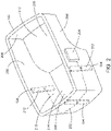
- FIG. 2 is a perspective view of an exemplary automobile oil pan 102 and oil level measuring components coupled to the oil pan 102.
- the components may include capacitive sensors 104, conductors (e.g., wires) 202 and electronics housing 204.
- the oil pan 102 includes an oil pan bottom 208, oil pan walls 206 extending a height from the oil pan bottom 208 and a reservoir 210 configured to hold oil defined by the oil pan walls 206 and oil pan bottom 208.
- the oil can 102 may include portions of different depths. For example, the bottom 208 of the oil pan 102 extends from a shallow portion 212 to a deeper portion 214.
- sensors 104 are disposed in the walls 206 at the deeper portion 214. In some embodiments, one or more sensors 104 may also be disposed at the shallow portion 212.
- Embodiments may include oil cans having any number of depth portions, including a single depth, more than two depths, and a continuously increasing depth portion (e.g., the oil can bottom has continuous slope from one end to another end).
- the size and shape of the automobile oil pan 102 shown in FIG. 2 is merely exemplary. Embodiments may include oil pans shaped and sized differently than the automobile oil pan 102 shown in FIG. 2 .
- the oil pan may be circular and include a single wall. Embodiments part of the claimed invention, however, include at least four walls.
- the oil pan 102 may be made of a conducting material, such as metal. In other embodiments, the oil pan 102 may be made of non-conducting material such as plastic.
- the wires 202 and electronics housing 204 are disposed on the outside (non-oil side) of the oil pan 102 away from the heat of the oil.
- Electronics housing 204 may be used to house processor 108, capacitance measuring unit 109, transmitter 110 and receiver 112 (shown in FIG. 1 ).
- the power source such as battery 106, may supply power to any of the components, such as processor 108, capacitance measuring unit 109, transmitter 110, receiver 112 and sensors 104.
- housing 204 may house the battery 106.
- the battery may be disposed separately from the housing 204 on the outside (non-oil side) of the oil pan 102.
- Both the sensors 104 and electronics may be sealed to limit or prevent contact with the oil or air to further increase the life of the system 100.
- the exemplary oil level measurement system 100 includes three rectangular capacitive sensors 104 disposed within the walls 206 of the oil pan 102.
- the number, size, shape and location of the capacitive sensors 104 shown at FIG. 2 are merely exemplary.
- embodiments may include oil level measurement systems having at least three capacitive sensors 104 coupled to the oil can 102, including one sensor.
- the capacitive sensors shown may include shapes other than rectangular. In some embodiments, sensors may be shaped differently from each other.
- the capacitive sensors 104 may include one or more sensor plates 212 comprising any conductive material, such as metal. As shown in FIG. 2 , the sensor plates 212 may be positioned substantially perpendicular to the oil pan bottom 208 and may be electrically connected to the capacitance measuring unit 109 (shown in FIG. 1 ) within electronics housing 204 using wires 202.
- the sensors 104 may be coupled to the oil pan 102 in different ways.
- the sensors 104 may be directly coupled to the oil pan 102 by contacting a portion of the oil pan 102.
- the sensors 104 may also be indirectly coupled to the oil pan 102 via one or more other portions, such as an insulation portion.
- the oil pan 102 may be made of a non-conductive material, such as plastic.
- the sensor plates 212 may be coupled to the oil pan 102 by being disposed inside (e.g., molded within) walls 206 or disposed outside of the oil pan (non-oil side).
- the capacitive sensors 104 are disposed within walls 206.
- the oil pan 102 may be made of a conductive material, such as metal.
- the sensor plates 212 may be disposed on the inside (oil side) of the oil pan walls 206.
- the oil container is made of a conductive material.
- FIG. 3 is a perspective view of an oil container 300 having a level of oil 302 and a capacitance sensor 104 disposed on an inside of a container wall 206 according to an embodiment.
- FIG. 4 is a close-up view of a capacitance sensor 104 disposed on an inside of a container wall 206 and insulated from the container wall 206 according to an embodiment. As shown in FIG. 3 and FIG.
- the sensor plates 212 of the capacitive sensors 104 are exposed to the reservoir 210.
- the sensor 104 is indirectly coupled to the oil pan 102 via an insulation portion 402 disposed between the container wall 206 and the sensor 104 to insulate the sensor 104 from the container wall 206.
- the wire e.g., wire 202 shown in FIG. 2
- the wire may be connected to the sensor 104 on the backside (non-oil side) of the sensor 104 and may pass through the wall 206 to the capacitance measuring unit 109.
- the capacitance measuring unit receives each capacitance obtained by the sensors 104 via the one or more wires 202 and determines capacitance values for each of the received capacitances.
- the capacitance readings are received by the measuring unit 109 via the wires 202.
- the capacitance measuring unit 109 may be configured to measure capacitance using different methods, including frequency tuning of an oscillator (not shown) and measurement of charge transfer onto the sensor plates 212 and off of the sensors plates 212.
- the measuring unit 109 measures the capacitances and sends the measured capacitance values to the processor 108.
- the processor 108 receives the capacitance values determined by the capacitance measuring unit and determines the oil level in the oil pan 102 based on the received capacitance values.
- the processor 108 may be coupled directly to the sensors 104 and may determine an oil level in the oil pan 102 based on the obtained capacitances from each of the sensors 104.
- the processor 108 determines an oil level value using the measured capacitance values and sends the oil level value to computer 114. In other embodiments, the processor 108 may send the capacitance values to the computer 114 and the computer 114 may determine the oil level value using the measured capacitances. The oil level may then be provided to a user (e.g., via user interface 116).
- wires 202 may be disposed in (e.g., molded inside) the oil pan walls 306. In other embodiments, such as when the oil pan 102 is made of a conductive material, wires 202 may be disposed along the outside of the walls 206. In some embodiments, the wires 202 may be contained in a metal shield (not shown). The shield may receive a signal from the capacitance measuring unit 109 that cancels the capacitance of the wires 202. The oil level may be determined based on the capacitance values received from the sensor plates without capacitance values from the wires. In some aspects, shields may be used behind the sensor plates 212 to prevent influences outside of the oil pan 102 from changing the capacitance values used to determine the oil level.
- While oil pans in motor vehicles may change between level states (level with the earth) and non-level states (e.g., automobile is tilted sideways, forward or backward at an angle relative to the earth), the surfaces of oil in the oil pans remain level with the earth.
- a single sensor 104 disposed on a wall 206 of the non-level oil pan 102 may report a capacitance value that is not an accurate representation (e.g., too high or too low) of the oil level.
- a sensor 104 may be located at a portion of the non-level oil pan 102 that is above the level of the oil while another sensor 104 may be located at an opposing portion of the non-level oil pan 102 that is below the level of the oil. Because the sensor plate 312 for each sensor 104 is independently connected to the capacitance measuring unit 109, the capacitances provided to the measuring unit 109 from each sensor 104 will be different from each other.
- the oil measuring system 100 may provide accurate oil level measurements from the different capacitance values regardless of the level of the motor vehicle and the oil pan 102.
- FIG. 2 shows three sensors 104 disposed at different locations of the oil pan 102. When the oil pan 102 is not level, the three sensors 104 may provide different sensed capacitance readings to the processor 102.
- the processor 102 may be configured to interpret the independent capacitance readings as coordinates in space and define the plane of the surface of the oil.
- the plane may be represented mathematically as an equation and the center coordinate of the oil pan 102 may be plugged into the equation and the true height of the oil may be determined.
- the following example is used to illustrate the determination of the oil level using three sensors 104 coupled to an oil pan having two side walls, a front wall and a back wall, a sensor 104 located in the center line of the oil pan (rear or front wall) and two other sensors 104 located on the opposing sides walls and equal distance from the center sensor 104.
- the capacitance corresponding to the level of the oil in the oil pan is given by the formula: ReadingC + ReadingR + ReadingL * Length of pan / 4 * length to side sensors
- ReadingC is the center sensor reading
- ReadingR is the relative reading of the right side sensor compared to the center sensor
- ReadingL is the relative reading of the left side sensor compared to the center sensor
- Length of pan is the length of the oil pan from front to back
- length to side sensors is the distance from the center sensor to the side sensors along the length of the oil pan (e.g., the length along the center line of the oil pan to a point in the oil pan at the intersection of a line drawn at a 90 degree angle to the side sensor).
- the oil level may be determined using three sensors for oil pans having different configurations. Embodiments may include any number of sensors, including less than three (not according to the invention), three (according to the invention), and more than three (according to the invention). The sensors may be located at any position along the oil pan.
- the oil level in the oil pan 102 may be determined by the processor 108 from the capacitances sensed across each of the sensor plates 212 and measured by the capacitance measuring unit 109.
- the oil level in the oil pan 102 may be sent to the computer 114 and provided (visually displayed or aurally provided) to a user (e.g., via a user interface such as a driver information center) in the automobile 100.
- Embodiments may include, for example, providing: a numerical level of the oil; an indication that the oil level is equal to or below an oil level threshold; and/or an indication that the oil level is equal to or above an oil level threshold.
- the oil level may be measured and provided automatically at equal time intervals (e.g., every 24 hours) or unequal time intervals.
- the oil measuring system 100 may automatically change periodically (e.g., every 24 hours) from a non-measuring state (e.g., powered off state, a hibernation state, or other non-measuring states) to a measuring state to measure the oil and send the oil level measurement information (e.g., via the RF transmitter 110) to the automobile's computer 114.
- the oil level may be measured and provided automatically upon request of a user or an electronic component (e.g., automobile computer) in response to the occurrence of an event (e.g., upon start of automobile).
- the oil measuring system 100 may, in response to receiving (e.g., via the RF receiver 112) a request for providing the oil level measurement information, measure the oil level and provide the oil level measurement information.
- the request may, for example, be from a component (e.g., automobile computer) of the automobile in response to the occurrence of an event, such as when the automobile 100 is turned on.
- the computer e.g., computer 114
- the processor 108 may cause (e.g., awaken, power-on, and the like) the processor 108 to provide the oil level measurement information to the computer 114.
- the request for providing the oil level measurement information may also be received via a user interface (e.g., a driver information center).
- the oil level measurement information may correspond to an oil level measurement taken at any time the automobile 100 is at rest (e.g., engine is not on), including a time when the oil is expected to be drained back into the oil pan 102, to provide for a more accurate measurement of the oil level.
- the oil level may be measured prior to the automobile 100 turning on and prior to the oil level measurement information being provided.
- the processor 108 may store oil level measurement information and provide the oil level measurement information when awakened (e.g., when automobile 100 is turned on).
- the processor 108 may also transmit the oil level measurement information to a storage unit (not shown), such as storage unit in the computer 114, prior to being awakened or requested to send the oil level measurement information.
- processor 108 may also transmit the oil level measurement information storage unit in the computer 114 responsive to the oil level being measured.
- the RF receiver 112 may receive an indication to measure an oil level (e.g., when the oil level measurement is requested via the user interface or via the computer 114 upon the automobile 100 being turned on).
- the oil measuring system 100 may not include a receiver.
- the oil level may be measured and/or provided automatically at equal time intervals without receiving a request to provide the oil level information.
- the transmitter 110 and receiver 112 may be configured to send and receive information via a wired or wireless system using any of the types of wireless technology standards described above.
- FIG. 5 is a graph illustrating the relationship between exemplary capacitance readings and the oil level in accordance with an embodiment.
- the exemplary capacitance readings in FIG. 5 are obtained using a single rectangular sensor vertically disposed along a height of an oil pan.
- the oil level increases substantially linearly along the height of the rectangular sensor as the capacitance increases.
- the known relationship between exemplary capacitance readings of a sensor and the oil level of a pan facilitates the determination of the oil level in oil pan oil by an exemplary measuring system, such as system 100.
- FIG. 6 illustrates an example of a computing environment 600 within which embodiments of the invention may be implemented.
- Computing environment 600 may be implemented as part of any component described herein.
- Computing environment 600 may include computer system 610, which is one example of a computing system upon which embodiments of the invention may be implemented.
- the computer system 610 may include a communication mechanism such as a bus 621 or other communication mechanism for communicating information within the computer system 610.
- the system 610 further includes one or more processors 620 coupled with the bus 621 for processing the information.
- the processors 620 may include one or more CPUs, GPUs, or any other processor known in the art.
- the computer system 610 also includes a system memory 630 coupled to the bus 621 for storing information and instructions to be executed by processors 620.
- the system memory 630 may include computer readable storage media in the form of volatile and/or nonvolatile memory, such as read only memory (ROM) 631 and/or random access memory (RAM) 632.
- the system memory RAM 632 may include other dynamic storage device(s) (e.g., dynamic RAM, static RAM, and synchronous DRAM).
- the system memory ROM 631 may include other static storage device(s) (e.g., programmable ROM, erasable PROM, and electrically erasable PROM).
- the system memory 630 may be used for storing temporary variables or other intermediate information during the execution of instructions by the processors 620.
- a basic input/output system 633 (BIOS) containing the basic routines that help to transfer information between elements within computer system 610, such as during start-up, may be stored in ROM 631.
- RAM 632 may contain data and/or program modules that are immediately accessible to and/or presently being operated on by the processors 620.
- System memory 630 may additionally include, for example, operating system 634, application programs 635, other program modules 636 and program data 637.
- the computer system 610 also includes a disk controller 640 coupled to the bus 621 to control one or more storage devices for storing information and instructions, such as a magnetic hard disk 641 and a removable media drive 642 (e.g., floppy disk drive, compact disc drive, tape drive, and/or solid state drive).
- the storage devices may be added to the computer system 610 using an appropriate device interface (e.g., a small computer system interface (SCSI), integrated device electronics (IDE), Universal Serial Bus (USB), or FireWire).
- SCSI small computer system interface
- IDE integrated device electronics
- USB Universal Serial Bus
- FireWire FireWire
- the computer system 610 may also include a display controller 665 coupled to the bus 621 to control a display or monitor 666, such as a cathode ray tube (CRT) or liquid crystal display (LCD), for displaying information to a computer user.
- the computer system 610 includes a user input interface 660 and one or more input devices, such as a keyboard 662 and a pointing device 661, for interacting with a computer user and providing information to the processor 620.
- the pointing device 661 for example, may be a mouse, a trackball, or a pointing stick for communicating direction information and command selections to the processor 620 and for controlling cursor movement on the display 666.
- the display 666 may provide a touch screen interface which allows input to supplement or replace the communication of direction information and command selections by the pointing device 661.
- the computer system 610 may perform a portion or all of the processing steps of embodiments of the invention in response to the processors 620 executing one or more sequences of one or more instructions contained in a memory, such as the system memory 630.
- a memory such as the system memory 630.
- Such instructions may be read into the system memory 630 from another computer readable medium, such as a hard disk 641 or a removable media drive 642.
- the hard disk 641 may contain one or more data stores and data files used by embodiments of the present invention. Data store contents and data files may be encrypted to improve security.
- the processors 620 may also be employed in a multi-processing arrangement to execute the one or more sequences of instructions contained in system memory 630.
- hard-wired circuitry may be used in place of or in combination with software instructions. Thus, embodiments are not limited to any specific combination of hardware circuitry and software.
- the computer system 610 may include at least one computer readable medium or memory for holding instructions programmed according to embodiments of the invention and for containing data structures, tables, records, or other data described herein.
- the term "computer readable medium” as used herein refers to any non-transitory, tangible medium that participates in providing instructions to the processor 620 for execution.
- a computer readable medium may take many forms including, but not limited to, non-volatile media, volatile media, and transmission media.
- Non-limiting examples of non-volatile media include optical disks, solid state drives, magnetic disks, and magneto-optical disks, such as hard disk 641 or removable media drive 642.
- Non-limiting examples of volatile media include dynamic memory, such as system memory 630.
- Non-limiting examples of transmission media include coaxial cables, copper wire, and fiber optics, including the wires that make up the bus 621.
- Transmission media may also take the form of acoustic or light waves, such as those generated during radio wave and infrared data communications.
- the computing environment 600 may further include the computer system 610 operating in a networked environment using logical connections to one or more remote computers, such as remote computer 680.
- Remote computer 680 may be a personal computer (laptop or desktop), a mobile device, a server, a router, a network PC, a peer device or other common network node, and typically includes many or all of the elements described above relative to computer 610.
- computer 610 may include modem 672 for establishing communications over a network 671, such as the Internet. Modem 672 may be connected to system bus 621 via network interface 670, or via another appropriate mechanism.
- Network 671 may be any network or system generally known in the art, including the Internet, an intranet, a local area network (LAN), a wide area network (WAN), a metropolitan area network (MAN), a direct connection or series of connections, a cellular telephone network, or any other network or medium capable of facilitating communication between computer system 610 and other computers (e.g., remote computing system 660).
- the network 671 may be wired, wireless or a combination thereof. Wired connections may be implemented using Ethernet, Universal Serial Bus (USB), RJ-11 or any other wired connection generally known in the art.
- Wireless connections may be implemented using Wi-Fi ® , WiMAX TM , and Bluetooth ® , infrared, cellular networks, satellite or any other wireless connection methodology generally known in the art. Additionally, several networks may work alone or in communication with each other to facilitate communication in the network 671.
- a processor as used herein is a device for executing machine-readable instructions stored on a computer readable medium, for performing tasks and may comprise any one or combination of, hardware and firmware.
- a processor may also comprise memory storing machine-readable instructions executable for performing tasks.
- a processor acts upon information by manipulating, analyzing, modifying, converting or transmitting information for use by an executable procedure or an information device, and/or by routing the information to an output device.
- a processor may use or comprise the capabilities of a computer, controller or microprocessor, for example, and is conditioned using executable instructions to perform special purpose functions not performed by a general purpose computer.
- a processor may be coupled (electrically and/or as comprising executable components) with any other processor enabling interaction and/or communication there-between.
- Computer program instructions may be loaded onto a computer, including without limitation, a general purpose computer or special purpose computer, or other programmable processing apparatus to produce a machine, such that the computer program instructions which execute on the computer or other programmable processing apparatus create means for implementing the functions specified in the block(s) of the flowchart(s).
- a user interface processor or generator is a known element comprising electronic circuitry or software or a combination of both for generating display elements or portions thereof.
- a user interface (UI) comprises one or more display elements enabling user interaction with a processor or other device.
- An executable application comprises code or machine readable instructions for conditioning the processor to implement predetermined functions, such as those of an operating system, a context data acquisition system or other information processing system, for example, in response to user command or input.
- An executable procedure is a segment of code or machine readable instruction, sub-routine, or other distinct section of code or portion of an executable application for performing one or more particular processes. These processes may include receiving input data and/or parameters, performing operations on received input data and/or performing functions in response to received input parameters, and providing resulting output data and/or parameters.
- GUI graphical user interface
- GUI comprises one or more display elements, generated by a display processor and enabling user interaction with a processor or other device and associated data acquisition and processing functions.
- the UI also includes an executable procedure or executable application.
- the executable procedure or executable application conditions the display processor to generate signals representing the UI display images. These signals are supplied to a display device which displays the elements for viewing by the user.
- the executable procedure or executable application further receives signals from user input devices, such as a keyboard, mouse, light pen, touch screen or any other means allowing a user to provide data to a processor.
- the processor under control of an executable procedure or executable application, manipulates the UI display elements in response to signals received from the input devices. In this way, the user interacts with the display elements using the input devices, enabling user interaction with the processor or other device.
- the functions and process steps herein may be performed automatically or wholly or partially in response to user command. An activity (including a step) performed automatically is performed in response to executable instruction or device operation without user direct initiation of the activity.
- a workflow processor processes data to determine tasks to add to, or remove from, a task list or modifies tasks incorporated on, or for incorporation on, a task list, as for example specified in a program(s).
- a task list is a list of tasks for performance by a worker, user of a device, or device or a combination of both.
- a workflow processor may or may not employ a workflow engine.
- a workflow engine is a processor executing in response to predetermined process definitions that implement processes responsive to events and event associated data. The workflow engine implements processes in sequence and/or concurrently, responsive to event associated data to determine tasks for performance by a device and or worker and for updating task lists of a device and a worker to include determined tasks.
- a process definition is definable by a user and comprises a sequence of process steps including one or more, of start, wait, decision and task allocation steps for performance by a device and or worker, for example.
- An event is an occurrence affecting operation of a process implemented using a process definition.
- the workflow engine includes a process definition function that allows users to define a process that is to be followed and may include an event monitor.
- a processor in the workflow engine tracks which processes are running, for which patients, physicians, and what step needs to be executed next, according to a process definition and may include a procedure for notifying physicians of a task to be performed.
Landscapes
- Engineering & Computer Science (AREA)
- Physics & Mathematics (AREA)
- Power Engineering (AREA)
- Mechanical Engineering (AREA)
- General Engineering & Computer Science (AREA)
- General Physics & Mathematics (AREA)
- Electromagnetism (AREA)
- Thermal Sciences (AREA)
- Fluid Mechanics (AREA)
- Measurement Of Levels Of Liquids Or Fluent Solid Materials (AREA)
- Investigating Or Analyzing Materials By The Use Of Electric Means (AREA)
- Lubrication Details And Ventilation Of Internal Combustion Engines (AREA)
Description
- The present disclosure relates to motor vehicle oil pans, and in particular, to motor vehicle oil pans with an integrated capacitive sensor for measuring oil level.
- Oil plays an important role in motor vehicles, providing lubrication, which may reduce wear and tear on components during operation of the motor vehicles. The oil reduces heat caused by friction when the components rub against one another during operation. When not being utilized, the oil is typically stored in an oil pan within a body of the motor vehicle. As the oil becomes depleted during operation, the oil's ability to perform effectively is degraded.
- In order to ensure that there is enough oil in the oil pan to perform effectively, the oil level in the pan is monitored periodically. Conventional methods and systems for monitoring the oil in the oil pan include a removable dipstick and manually monitoring the oil level by removing the dipstick and observing the oil on the dipstick.
-
EP1722203A2 discloses a measuring system having several sensor surfaces for arrangement at the wall of a container, and an evaluation unit for determining the level of the container from measuring signals of individual sensor surfaces. - The claimed invention provides an oil pan according to claim 1.
- Embodiments provide an oil level measuring system according to claim 9.
- Embodiments provide a motor vehicle according to claim 13.
- A more detailed understanding may be had from the following description, given by way of example in conjunction with the accompanying drawings wherein:
-
FIG. 1 is a system block diagram of an exemplary oil level measurement system according to embodiments disclosed herein; -
FIG. 2 is a perspective view of an exemplary automobile oil pan and oil level measuring components coupled to the oil pan for use with embodiments disclosed herein; -
FIG. 3 is a perspective view of an oil container having a level of oil and a capacitance sensor disposed on an inside of a container wall according to an embodiment disclosed herein; -
FIG. 4 is a close-up view of a capacitance sensor disposed on an inside of a container wall and insulated from the container wall according to an embodiment; -
FIG. 5 is a graph illustrating the relationship between exemplary capacitance readings and the oil level in accordance with an embodiment; and -
FIG. 6 illustrates an example of a computing environment within which embodiments of the invention may be implemented. - Embodiments include methods and systems that measure oil levels of oil containers, such as oil pans, in different types of motorized vehicles, such as automobiles (cars), trucks, buses, motorcycles, watercrafts (e.g., ships and boats) and aircrafts. For simplification of explanation, however, embodiments described herein include methods and systems that measure oil levels of oil containers in an
automobile 100. -
FIG. 1 is a system diagram of an exemplary oillevel measurement system 100. As shown inFIG 1 , the exemplary oillevel measurement system 100 includes anoil pan 102 with three ormore sensors 104. The oil level measurement system may include a power source, such asbattery 106 shown inFIG. 1 . The oil pan includes aprocessor 108 and may also include acapacitance measuring unit 109, atransmitter 110 and areceiver 112. The oil level measurement system may include acomputer 114 and auser interface 116. In some embodiments, thetransmitter 110 andreceiver 112 may be integrated as a single transceiver unit. In some embodiments, the oillevel measurement system 100 may not include a receiver 112 (as described in more detail below). - Many modern vehicles include computers that may monitor various aspects of vehicle performance. Some embodiments disclosed herein utilize the computers included in motor vehicles to provide the oil levels in the oil pans. For example, the
computer 114 may be a motor vehicle computer, such as an automobile computer (e.g., computer in communication with different automobile systems). Thecomputer 114 may also be separate from the automobile computer. Thecomputer 114 may also be in communication with a motor vehicle computer. - Each of the measurement components may be part of a wired or wireless system. For example, in one embodiment, the
processor 108, thecomputer 114, thetransmitter 110 and thereceiver 112 may be wired to each other. In another embodiment, theprocessor 108 andcomputer 114 may communicate wirelessly via awireless transmitter 110 andreceiver 112, such as a radio frequency (RF) transmitter and RF receiver. Information may be transmitted and received using any frequency and packet formatting from a number of different types of wireless technology standards (e.g., Industrial, Scientific and Medical (ISM) band typically used in tire pressure monitoring systems TPMS function, Bluetooth®, ANT+, and the like). The information may also be transmitted using any frequency selected by a motor vehicle manufacturer. -
FIG. 2 is a perspective view of an exemplaryautomobile oil pan 102 and oil level measuring components coupled to theoil pan 102. As shown inFIG. 2 , the components may includecapacitive sensors 104, conductors (e.g., wires) 202 andelectronics housing 204. Theoil pan 102 includes anoil pan bottom 208,oil pan walls 206 extending a height from theoil pan bottom 208 and areservoir 210 configured to hold oil defined by theoil pan walls 206 andoil pan bottom 208. As shown inFIG. 2 , the oil can 102 may include portions of different depths. For example, thebottom 208 of theoil pan 102 extends from ashallow portion 212 to adeeper portion 214. In this embodiment,sensors 104 are disposed in thewalls 206 at thedeeper portion 214. In some embodiments, one ormore sensors 104 may also be disposed at theshallow portion 212. Embodiments may include oil cans having any number of depth portions, including a single depth, more than two depths, and a continuously increasing depth portion (e.g., the oil can bottom has continuous slope from one end to another end). - The size and shape of the
automobile oil pan 102 shown inFIG. 2 is merely exemplary. Embodiments may include oil pans shaped and sized differently than theautomobile oil pan 102 shown inFIG. 2 . In one embodiment not part of the claimed invention, the oil pan may be circular and include a single wall. Embodiments part of the claimed invention, however, include at least four walls. In some embodiments, theoil pan 102 may be made of a conducting material, such as metal. In other embodiments, theoil pan 102 may be made of non-conducting material such as plastic. - As shown in
FIG. 2 , thewires 202 andelectronics housing 204 are disposed on the outside (non-oil side) of theoil pan 102 away from the heat of the oil.Electronics housing 204 may be used to houseprocessor 108,capacitance measuring unit 109,transmitter 110 and receiver 112 (shown inFIG. 1 ). The power source, such asbattery 106, may supply power to any of the components, such asprocessor 108,capacitance measuring unit 109,transmitter 110,receiver 112 andsensors 104. In some embodiments,housing 204 may house thebattery 106. In other embodiments, the battery may be disposed separately from thehousing 204 on the outside (non-oil side) of theoil pan 102. Disposing theelectronics housing 204 andbattery 106 on the outside of the oil pan and away from the heat of the oil facilitates an efficient and long-lasting system, having low maintenance that may merely include replacing thebattery 106, such as after a typical batter life of 5-10 years. Both thesensors 104 and electronics (e.g.,processor 108,capacitance measuring unit 109,transmitter 110, and receiver 112) may be sealed to limit or prevent contact with the oil or air to further increase the life of thesystem 100. - In the embodiment shown at
FIG. 2 , the exemplary oillevel measurement system 100 includes three rectangularcapacitive sensors 104 disposed within thewalls 206 of theoil pan 102. The number, size, shape and location of thecapacitive sensors 104 shown atFIG. 2 are merely exemplary. According to the claimed invention, embodiments may include oil level measurement systems having at least threecapacitive sensors 104 coupled to the oil can 102, including one sensor. The capacitive sensors shown may include shapes other than rectangular. In some embodiments, sensors may be shaped differently from each other. - The
capacitive sensors 104 may include one ormore sensor plates 212 comprising any conductive material, such as metal. As shown inFIG. 2 , thesensor plates 212 may be positioned substantially perpendicular to theoil pan bottom 208 and may be electrically connected to the capacitance measuring unit 109 (shown inFIG. 1 ) withinelectronics housing 204 usingwires 202. - The
sensors 104 may be coupled to theoil pan 102 in different ways. For example, thesensors 104 may be directly coupled to theoil pan 102 by contacting a portion of theoil pan 102. Thesensors 104 may also be indirectly coupled to theoil pan 102 via one or more other portions, such as an insulation portion. - In some embodiments, the
oil pan 102 may be made of a non-conductive material, such as plastic. When theoil pan 102 is made of non-conducting material, thesensor plates 212 may be coupled to theoil pan 102 by being disposed inside (e.g., molded within)walls 206 or disposed outside of the oil pan (non-oil side). For example, in the embodiment shown inFIG. 2 , thecapacitive sensors 104 are disposed withinwalls 206. - In other embodiments, the
oil pan 102 may be made of a conductive material, such as metal. When theoil pan 102 is made of a conductive material, thesensor plates 212 may be disposed on the inside (oil side) of theoil pan walls 206. In the embodiments shown inFIG. 3 andFIG. 4 , the oil container is made of a conductive material.FIG. 3 is a perspective view of anoil container 300 having a level ofoil 302 and acapacitance sensor 104 disposed on an inside of acontainer wall 206 according to an embodiment.FIG. 4 is a close-up view of acapacitance sensor 104 disposed on an inside of acontainer wall 206 and insulated from thecontainer wall 206 according to an embodiment. As shown inFIG. 3 andFIG. 4 , thesensor plates 212 of thecapacitive sensors 104 are exposed to thereservoir 210. As shown inFIG. 4 , thesensor 104 is indirectly coupled to theoil pan 102 via aninsulation portion 402 disposed between thecontainer wall 206 and thesensor 104 to insulate thesensor 104 from thecontainer wall 206. The wire (e.g.,wire 202 shown inFIG. 2 ) may be connected to thesensor 104 on the backside (non-oil side) of thesensor 104 and may pass through thewall 206 to thecapacitance measuring unit 109. - As the oil level rises within the
oil pan 102, the amount of eachsensor plate 212 proximate to or in contact with the oil increases. Accordingly, the capacitance across each correspondingsensor plate 212 ofsensors 104 also increases. The capacitance measuring unit receives each capacitance obtained by thesensors 104 via the one ormore wires 202 and determines capacitance values for each of the received capacitances. The capacitance readings are received by the measuringunit 109 via thewires 202. Thecapacitance measuring unit 109 may be configured to measure capacitance using different methods, including frequency tuning of an oscillator (not shown) and measurement of charge transfer onto thesensor plates 212 and off of thesensors plates 212. - The measuring
unit 109 measures the capacitances and sends the measured capacitance values to theprocessor 108. Theprocessor 108 receives the capacitance values determined by the capacitance measuring unit and determines the oil level in theoil pan 102 based on the received capacitance values. In some embodiments, theprocessor 108 may be coupled directly to thesensors 104 and may determine an oil level in theoil pan 102 based on the obtained capacitances from each of thesensors 104. - In some embodiments, the
processor 108 determines an oil level value using the measured capacitance values and sends the oil level value tocomputer 114. In other embodiments, theprocessor 108 may send the capacitance values to thecomputer 114 and thecomputer 114 may determine the oil level value using the measured capacitances. The oil level may then be provided to a user (e.g., via user interface 116). - In some embodiments, such as when the
oil pan 102 is made of a non-conductive material,wires 202 may be disposed in (e.g., molded inside) the oil pan walls 306. In other embodiments, such as when theoil pan 102 is made of a conductive material,wires 202 may be disposed along the outside of thewalls 206. In some embodiments, thewires 202 may be contained in a metal shield (not shown). The shield may receive a signal from thecapacitance measuring unit 109 that cancels the capacitance of thewires 202. The oil level may be determined based on the capacitance values received from the sensor plates without capacitance values from the wires. In some aspects, shields may be used behind thesensor plates 212 to prevent influences outside of theoil pan 102 from changing the capacitance values used to determine the oil level. - While oil pans in motor vehicles may change between level states (level with the earth) and non-level states (e.g., automobile is tilted sideways, forward or backward at an angle relative to the earth), the surfaces of oil in the oil pans remain level with the earth. When an oil pan is not level, a
single sensor 104 disposed on awall 206 of thenon-level oil pan 102 may report a capacitance value that is not an accurate representation (e.g., too high or too low) of the oil level. For example, asensor 104 may be located at a portion of thenon-level oil pan 102 that is above the level of the oil while anothersensor 104 may be located at an opposing portion of thenon-level oil pan 102 that is below the level of the oil. Because the sensor plate 312 for eachsensor 104 is independently connected to thecapacitance measuring unit 109, the capacitances provided to the measuringunit 109 from eachsensor 104 will be different from each other. - The
oil measuring system 100 may provide accurate oil level measurements from the different capacitance values regardless of the level of the motor vehicle and theoil pan 102. For example,FIG. 2 shows threesensors 104 disposed at different locations of theoil pan 102. When theoil pan 102 is not level, the threesensors 104 may provide different sensed capacitance readings to theprocessor 102. Theprocessor 102 may be configured to interpret the independent capacitance readings as coordinates in space and define the plane of the surface of the oil. The plane may be represented mathematically as an equation and the center coordinate of theoil pan 102 may be plugged into the equation and the true height of the oil may be determined. The following example is used to illustrate the determination of the oil level using threesensors 104 coupled to an oil pan having two side walls, a front wall and a back wall, asensor 104 located in the center line of the oil pan (rear or front wall) and twoother sensors 104 located on the opposing sides walls and equal distance from thecenter sensor 104. According to the invention, the capacitance corresponding to the level of the oil in the oil pan is given by the formula:
where ReadingC is the center sensor reading, ReadingR is the relative reading of the right side sensor compared to the center sensor, ReadingL is the relative reading of the left side sensor compared to the center sensor, Length of pan is the length of the oil pan from front to back, and length to side sensors is the distance from the center sensor to the side sensors along the length of the oil pan (e.g., the length along the center line of the oil pan to a point in the oil pan at the intersection of a line drawn at a 90 degree angle to the side sensor). If the oil occupies part of the pan (low level), then the length of the oil pan in the formula is modified to the length that the oil occupies. If the readings from each of the three sensors are the same, then the formula simplifies to just the original reading of the center sensor (no tilt or correction). The oil level may be determined using three sensors for oil pans having different configurations. Embodiments may include any number of sensors, including less than three (not according to the invention), three (according to the invention), and more than three (according to the invention). The sensors may be located at any position along the oil pan. - The oil level in the
oil pan 102 may be determined by theprocessor 108 from the capacitances sensed across each of thesensor plates 212 and measured by thecapacitance measuring unit 109. The oil level in theoil pan 102 may be sent to thecomputer 114 and provided (visually displayed or aurally provided) to a user (e.g., via a user interface such as a driver information center) in theautomobile 100. Embodiments may include, for example, providing: a numerical level of the oil; an indication that the oil level is equal to or below an oil level threshold; and/or an indication that the oil level is equal to or above an oil level threshold. - In another embodiment, the oil level may be measured and provided automatically at equal time intervals (e.g., every 24 hours) or unequal time intervals. For example, the
oil measuring system 100 may automatically change periodically (e.g., every 24 hours) from a non-measuring state (e.g., powered off state, a hibernation state, or other non-measuring states) to a measuring state to measure the oil and send the oil level measurement information (e.g., via the RF transmitter 110) to the automobile'scomputer 114. In another embodiment, the oil level may be measured and provided automatically upon request of a user or an electronic component (e.g., automobile computer) in response to the occurrence of an event (e.g., upon start of automobile). For example, theoil measuring system 100 may, in response to receiving (e.g., via the RF receiver 112) a request for providing the oil level measurement information, measure the oil level and provide the oil level measurement information. The request may, for example, be from a component (e.g., automobile computer) of the automobile in response to the occurrence of an event, such as when theautomobile 100 is turned on. For example, when theautomobile 100 is turned on, the computer (e.g., computer 114) may cause (e.g., awaken, power-on, and the like) theprocessor 108 to provide the oil level measurement information to thecomputer 114. The request for providing the oil level measurement information may also be received via a user interface (e.g., a driver information center). - The oil level measurement information may correspond to an oil level measurement taken at any time the
automobile 100 is at rest (e.g., engine is not on), including a time when the oil is expected to be drained back into theoil pan 102, to provide for a more accurate measurement of the oil level. The oil level may be measured prior to theautomobile 100 turning on and prior to the oil level measurement information being provided. Theprocessor 108 may store oil level measurement information and provide the oil level measurement information when awakened (e.g., whenautomobile 100 is turned on). Theprocessor 108 may also transmit the oil level measurement information to a storage unit (not shown), such as storage unit in thecomputer 114, prior to being awakened or requested to send the oil level measurement information. For example,processor 108 may also transmit the oil level measurement information storage unit in thecomputer 114 responsive to the oil level being measured. - In some embodiments, the
RF receiver 112 may receive an indication to measure an oil level (e.g., when the oil level measurement is requested via the user interface or via thecomputer 114 upon theautomobile 100 being turned on). In other embodiments, theoil measuring system 100 may not include a receiver. For example, the oil level may be measured and/or provided automatically at equal time intervals without receiving a request to provide the oil level information. Thetransmitter 110 andreceiver 112 may be configured to send and receive information via a wired or wireless system using any of the types of wireless technology standards described above. -
FIG. 5 is a graph illustrating the relationship between exemplary capacitance readings and the oil level in accordance with an embodiment. The exemplary capacitance readings inFIG. 5 are obtained using a single rectangular sensor vertically disposed along a height of an oil pan. The oil level inFIG. 5 is measured in inches (in.; 1 inch = approx. 0.0254 meters) and capacitance is measured in picofarads (pF; 1 picofarad = 10-12kg-1m-2s4A2). As shown inFIG. 5 , the oil level increases substantially linearly along the height of the rectangular sensor as the capacitance increases. The known relationship between exemplary capacitance readings of a sensor and the oil level of a pan facilitates the determination of the oil level in oil pan oil by an exemplary measuring system, such assystem 100. -
FIG. 6 illustrates an example of acomputing environment 600 within which embodiments of the invention may be implemented.Computing environment 600 may be implemented as part of any component described herein.Computing environment 600 may includecomputer system 610, which is one example of a computing system upon which embodiments of the invention may be implemented. As shown inFIG. 6 , thecomputer system 610 may include a communication mechanism such as a bus 621 or other communication mechanism for communicating information within thecomputer system 610. Thesystem 610 further includes one ormore processors 620 coupled with the bus 621 for processing the information. Theprocessors 620 may include one or more CPUs, GPUs, or any other processor known in the art. - The
computer system 610 also includes asystem memory 630 coupled to the bus 621 for storing information and instructions to be executed byprocessors 620. Thesystem memory 630 may include computer readable storage media in the form of volatile and/or nonvolatile memory, such as read only memory (ROM) 631 and/or random access memory (RAM) 632. Thesystem memory RAM 632 may include other dynamic storage device(s) (e.g., dynamic RAM, static RAM, and synchronous DRAM). Thesystem memory ROM 631 may include other static storage device(s) (e.g., programmable ROM, erasable PROM, and electrically erasable PROM). In addition, thesystem memory 630 may be used for storing temporary variables or other intermediate information during the execution of instructions by theprocessors 620. A basic input/output system 633 (BIOS) containing the basic routines that help to transfer information between elements withincomputer system 610, such as during start-up, may be stored inROM 631.RAM 632 may contain data and/or program modules that are immediately accessible to and/or presently being operated on by theprocessors 620.System memory 630 may additionally include, for example,operating system 634,application programs 635,other program modules 636 andprogram data 637. - The
computer system 610 also includes adisk controller 640 coupled to the bus 621 to control one or more storage devices for storing information and instructions, such as a magnetichard disk 641 and a removable media drive 642 (e.g., floppy disk drive, compact disc drive, tape drive, and/or solid state drive). The storage devices may be added to thecomputer system 610 using an appropriate device interface (e.g., a small computer system interface (SCSI), integrated device electronics (IDE), Universal Serial Bus (USB), or FireWire). - The
computer system 610 may also include adisplay controller 665 coupled to the bus 621 to control a display or monitor 666, such as a cathode ray tube (CRT) or liquid crystal display (LCD), for displaying information to a computer user. Thecomputer system 610 includes auser input interface 660 and one or more input devices, such as akeyboard 662 and apointing device 661, for interacting with a computer user and providing information to theprocessor 620. Thepointing device 661, for example, may be a mouse, a trackball, or a pointing stick for communicating direction information and command selections to theprocessor 620 and for controlling cursor movement on thedisplay 666. Thedisplay 666 may provide a touch screen interface which allows input to supplement or replace the communication of direction information and command selections by thepointing device 661. - The
computer system 610 may perform a portion or all of the processing steps of embodiments of the invention in response to theprocessors 620 executing one or more sequences of one or more instructions contained in a memory, such as thesystem memory 630. Such instructions may be read into thesystem memory 630 from another computer readable medium, such as ahard disk 641 or aremovable media drive 642. Thehard disk 641 may contain one or more data stores and data files used by embodiments of the present invention. Data store contents and data files may be encrypted to improve security. Theprocessors 620 may also be employed in a multi-processing arrangement to execute the one or more sequences of instructions contained insystem memory 630. In alternative embodiments, hard-wired circuitry may be used in place of or in combination with software instructions. Thus, embodiments are not limited to any specific combination of hardware circuitry and software. - As stated above, the
computer system 610 may include at least one computer readable medium or memory for holding instructions programmed according to embodiments of the invention and for containing data structures, tables, records, or other data described herein. The term "computer readable medium" as used herein refers to any non-transitory, tangible medium that participates in providing instructions to theprocessor 620 for execution. A computer readable medium may take many forms including, but not limited to, non-volatile media, volatile media, and transmission media. Non-limiting examples of non-volatile media include optical disks, solid state drives, magnetic disks, and magneto-optical disks, such ashard disk 641 or removable media drive 642. Non-limiting examples of volatile media include dynamic memory, such assystem memory 630. Non-limiting examples of transmission media include coaxial cables, copper wire, and fiber optics, including the wires that make up the bus 621. Transmission media may also take the form of acoustic or light waves, such as those generated during radio wave and infrared data communications. - The
computing environment 600 may further include thecomputer system 610 operating in a networked environment using logical connections to one or more remote computers, such asremote computer 680.Remote computer 680 may be a personal computer (laptop or desktop), a mobile device, a server, a router, a network PC, a peer device or other common network node, and typically includes many or all of the elements described above relative tocomputer 610. When used in a networking environment,computer 610 may includemodem 672 for establishing communications over anetwork 671, such as the Internet.Modem 672 may be connected to system bus 621 vianetwork interface 670, or via another appropriate mechanism. -
Network 671 may be any network or system generally known in the art, including the Internet, an intranet, a local area network (LAN), a wide area network (WAN), a metropolitan area network (MAN), a direct connection or series of connections, a cellular telephone network, or any other network or medium capable of facilitating communication betweencomputer system 610 and other computers (e.g., remote computing system 660). Thenetwork 671 may be wired, wireless or a combination thereof. Wired connections may be implemented using Ethernet, Universal Serial Bus (USB), RJ-11 or any other wired connection generally known in the art. Wireless connections may be implemented using Wi-Fi®, WiMAX™, and Bluetooth®, infrared, cellular networks, satellite or any other wireless connection methodology generally known in the art. Additionally, several networks may work alone or in communication with each other to facilitate communication in thenetwork 671. - A processor as used herein is a device for executing machine-readable instructions stored on a computer readable medium, for performing tasks and may comprise any one or combination of, hardware and firmware. A processor may also comprise memory storing machine-readable instructions executable for performing tasks. A processor acts upon information by manipulating, analyzing, modifying, converting or transmitting information for use by an executable procedure or an information device, and/or by routing the information to an output device. A processor may use or comprise the capabilities of a computer, controller or microprocessor, for example, and is conditioned using executable instructions to perform special purpose functions not performed by a general purpose computer. A processor may be coupled (electrically and/or as comprising executable components) with any other processor enabling interaction and/or communication there-between. Computer program instructions may be loaded onto a computer, including without limitation, a general purpose computer or special purpose computer, or other programmable processing apparatus to produce a machine, such that the computer program instructions which execute on the computer or other programmable processing apparatus create means for implementing the functions specified in the block(s) of the flowchart(s). A user interface processor or generator is a known element comprising electronic circuitry or software or a combination of both for generating display elements or portions thereof. A user interface (UI) comprises one or more display elements enabling user interaction with a processor or other device.
- An executable application, as used herein, comprises code or machine readable instructions for conditioning the processor to implement predetermined functions, such as those of an operating system, a context data acquisition system or other information processing system, for example, in response to user command or input. An executable procedure is a segment of code or machine readable instruction, sub-routine, or other distinct section of code or portion of an executable application for performing one or more particular processes. These processes may include receiving input data and/or parameters, performing operations on received input data and/or performing functions in response to received input parameters, and providing resulting output data and/or parameters. A graphical user interface (GUI), as used herein, comprises one or more display elements, generated by a display processor and enabling user interaction with a processor or other device and associated data acquisition and processing functions.
- The UI also includes an executable procedure or executable application. The executable procedure or executable application conditions the display processor to generate signals representing the UI display images. These signals are supplied to a display device which displays the elements for viewing by the user. The executable procedure or executable application further receives signals from user input devices, such as a keyboard, mouse, light pen, touch screen or any other means allowing a user to provide data to a processor. The processor, under control of an executable procedure or executable application, manipulates the UI display elements in response to signals received from the input devices. In this way, the user interacts with the display elements using the input devices, enabling user interaction with the processor or other device. The functions and process steps herein may be performed automatically or wholly or partially in response to user command. An activity (including a step) performed automatically is performed in response to executable instruction or device operation without user direct initiation of the activity.
- A workflow processor, as used herein, processes data to determine tasks to add to, or remove from, a task list or modifies tasks incorporated on, or for incorporation on, a task list, as for example specified in a program(s). A task list is a list of tasks for performance by a worker, user of a device, or device or a combination of both. A workflow processor may or may not employ a workflow engine. A workflow engine, as used herein, is a processor executing in response to predetermined process definitions that implement processes responsive to events and event associated data. The workflow engine implements processes in sequence and/or concurrently, responsive to event associated data to determine tasks for performance by a device and or worker and for updating task lists of a device and a worker to include determined tasks. A process definition is definable by a user and comprises a sequence of process steps including one or more, of start, wait, decision and task allocation steps for performance by a device and or worker, for example. An event is an occurrence affecting operation of a process implemented using a process definition. The workflow engine includes a process definition function that allows users to define a process that is to be followed and may include an event monitor. A processor in the workflow engine tracks which processes are running, for which patients, physicians, and what step needs to be executed next, according to a process definition and may include a procedure for notifying physicians of a task to be performed.
- The system and processes of the figures presented herein are not exclusive. Other systems, processes and menus may be derived in accordance with the principles of the invention to accomplish the same objectives. Although this invention has been described with reference to particular embodiments, it is to be understood that the embodiments and variations shown and described herein are for illustration purposes only. Modifications to the current design may be implemented by those skilled in the art, without departing from the scope of the invention. Further, the processes and applications may, in alternative embodiments, be located on one or more (e.g., distributed) processing devices on a network linking the units of
FIG. 6 . Any of the functions and steps provided in the Figures may be implemented in hardware, software or a combination of both.
Claims (13)
- An oil pan (102) comprising:an oil pan bottom (208);four or more oil pan walls (206) extending a height between the oil pan bottom (208) and a top of the oil pan walls (206), wherein the oil pan walls include two side walls opposing one another, a front wall, and a back wall;a reservoir (210) configured to hold oil, the reservoir defined by the oil pan walls (206) and the oil pan bottom (208);three or more capacitance sensors (104), each capacitance sensor (104) coupled to a portion of the oil pan walls (206) and each configured to sense a capacitance, wherein a first capacitance sensor (104) of the three or more capacitance sensors (104) is located on one of the front wall or the back wall in a center line of the oil pan (102) such that the first capacitance sensor is a center sensor, a second capacitance sensor is located on one of the two side walls, and a third capacitance sensor is located on the other of the two side walls, wherein a length extending from the second capacitance sensor to the first capacitance sensor is equidistant to a length extending from the third capacitance sensor to the first capacitance sensor along the length of the oil pan; anda processor (108) configured to determine an oil level in the oil pan (102) based on sensed capacitances from each of the three or more capacitance sensors (104), wherein the processor (108) is further configured to:interpret the sensed capacitances from each of the three or more capacitance sensors (104) as coordinates in space,define a plane of a surface of the oil using the sensed capacitance values from each of the three or more capacitance sensors (104), anddetermine the oil level based on the coordinates, the plane defined by the processor (108), and a center coordinate of the oil pan (102) as defined by the first capacitance sensor (104), wherein the capacitance corresponding to the level of the oil in the oil pan (102) is given by the formula:
 where ReadingC is a center sensor reading,ReadingR is a relative reading of the right side sensor (104) compared to the center sensor (104),ReadingL is the relative reading of the left side sensor (104) compared to the center sensor (104),Length of the pan is the length of the oil pan (102) along the center line from front to back,and the length to side sensors is the distance from the center sensor (104) to the side sensors (104) along the length of the oil pan (102), which is the length along the center line of the oil pan to a point in the oil pan at the intersection of a line drawn perpendicular to the side sensors.
 - The oil pan of claim 1, further comprising:three or more conductors coupled to the three or more capacitance sensors; anda capacitance measuring unit electrically connected to the three or more capacitance sensors via the three or more conductors and configured to receive each of the sensed capacitances via the three or more conductors and determine capacitance values for each of the sensed capacitances,wherein the processor is configured to receive the capacitance values and determine the oil level in the oil pan based on the capacitance values.
- The oil pan of claim 1, further comprising:a transmitter configured to transmit an oil level value, corresponding to the determined oil level; anda receiver configured to receive a request to provide the oil level.
- The oil pan of claim 3, wherein the transmitter and receiver are configured to communicate wirelessly.
- The oil pan of claim 3, wherein the receiver is configured to receive a request for the oil level andthe processor is configured to automatically provide the oil level upon receiving the request; or whereinthe processor is configured to automatically provide the oil level at equal time intervals.
- The oil pan of claim 1, further comprising a storage unit, wherein the processor is further configured to transmit the oil level value to the storage unit.
- The oil pan of claim 1, whereinthe four or more oil pan walls (206) are non-conductive and the three or more capacitive sensors (104) are at least one of: disposed inside the four or more oil pan walls and disposed outside of the oil pan walls; orthe four or more oil pan walls are conductive and the three or more sensors are disposed on the inside of the one or more oil pan walls.
- The oil pan of claim 2, further comprising a shield configured to house the three or more conductors, wherein the shield is configured to receive a signal from the capacitance measuring unit that cancels the capacitance of the wires and the capacitance measuring unit is configured to determine the capacitance values for each of the sensed capacitances without interference from capacitance of the three or more conductors.
- An oil level measuring system (100) for use with a motor vehicle, the oil level measuring system (100) comprising:the oil pan (102) according to any one of claims 3,5-8; a power source; anda motor vehicle computer configured to provide the determined oil level to a user; whereinthe receiver is configured to receive a request from the motor vehicle computer to provide the oil level; andthe transmitter is configured to transmit an oil level value, corresponding to the determined oil level, to the motor vehicle computer.
- The measuring system of claim 9, wherein the transmitter and receiver are configured to communicate wirelessly.
- The measuring system of claim 9, wherein the receiver is configured to receive a request from the motor vehicle computer in response to an occurrence of an event for the oil level and the processor is configured to automatically provide the oil level upon receiving the request from the motor vehicle computer for the oil level in response to the occurrence of an event.
- The measuringsystem of claim 9, further comprising a user interface, whereinthe user interface is configured to receive a request by a user to provide the oil level, andthe receiver is configured to receive the request by a user and the processor is configured to automatically provide the oil level in response to the request by a user.
- A motor vehicle comprising:a motor vehicle body; andthe oil level measuring system (100) according to any one of claims 9-12.
Applications Claiming Priority (3)
| Application Number | Priority Date | Filing Date | Title |
|---|---|---|---|
| US201562114857P | 2015-02-11 | 2015-02-11 | |
| US14/946,441 US9587534B2 (en) | 2015-02-11 | 2015-11-19 | Oil pan with integrated capacitive sensor for measuring oil level |
| PCT/US2016/017616 WO2016130848A1 (en) | 2015-02-11 | 2016-02-11 | Oil pan with integrated capacitive sensor for measuring oil level |
Publications (2)
| Publication Number | Publication Date |
|---|---|
| EP3256823A1 EP3256823A1 (en) | 2017-12-20 |
| EP3256823B1 true EP3256823B1 (en) | 2022-08-17 |
Family
ID=56565809
Family Applications (1)
| Application Number | Title | Priority Date | Filing Date |
|---|---|---|---|
| EP16708530.7A Active EP3256823B1 (en) | 2015-02-11 | 2016-02-11 | Oil pan with integrated capacitive sensor for measuring oil level |
Country Status (4)
| Country | Link |
|---|---|
| US (1) | US9587534B2 (en) |
| EP (1) | EP3256823B1 (en) |
| CN (1) | CN107407169B (en) |
| WO (1) | WO2016130848A1 (en) |
Families Citing this family (11)
| Publication number | Priority date | Publication date | Assignee | Title |
|---|---|---|---|---|
| EP2417333B1 (en) * | 2009-04-06 | 2019-06-05 | Wärtsilä Schweiz AG | Monitoring device and monitoring method for monitoring a state of wear of a component of a reciprocating internal combustion engine |
| US11280042B2 (en) * | 2017-05-03 | 2022-03-22 | Nypro Inc. | Apparatus, system, and method of providing a liquid level monitor |
| CN112040823A (en) * | 2018-03-16 | 2020-12-04 | 皮特科炸具股份有限公司 | Filter Disc Inspection and Fluid Sensor System |
| EP3788326B1 (en) | 2018-05-03 | 2025-08-06 | Nypro Inc. | System of providing a content level monitor |
| CN112243490A (en) | 2018-05-03 | 2021-01-19 | 耐普罗公司 | Apparatus, system and method for providing a solids level monitor |
| CN108678834A (en) * | 2018-05-11 | 2018-10-19 | 浙江吉利控股集团有限公司 | The engine electric-controlled automatic assisting vehicle oil system of one kind and assisting vehicle oil method |
| US20210310850A1 (en) * | 2018-11-26 | 2021-10-07 | Parker-Hannifin Corporation | Non-contact, remotely-monitored, level sensor system |
| DE102019109274A1 (en) * | 2019-04-09 | 2020-10-15 | Carl Freudenberg Kg | Device for measuring physical properties of a liquid with a sensor tape |
| US11614200B2 (en) * | 2019-12-30 | 2023-03-28 | Dodge Industrial, Inc. | Automatic lubrication system for lubricating an object |
| EP4039948B1 (en) * | 2021-02-09 | 2024-05-29 | Volvo Penta Corporation | Method and system for checking an oil level in a marine drive unit |
| US20250137883A1 (en) * | 2023-11-01 | 2025-05-01 | Progress Rail Locomotive Inc. | Engine oil system health monitoring using oil level sensor |
Family Cites Families (20)
| Publication number | Priority date | Publication date | Assignee | Title |
|---|---|---|---|---|
| IT1128919B (en) * | 1980-07-09 | 1986-06-04 | Fiat Auto Spa | AUTOMATIC DEVICE FOR SIGNALING OF INSUFFICIENT LEVEL OR LIO OF AUTOMATIC TYPE GEARBOXES FOR VEHICLES |
| JPS57101724A (en) * | 1980-12-17 | 1982-06-24 | Nissan Motor Co Ltd | Engine oil remainder weighing scale |
| EP0610050B1 (en) | 1993-02-01 | 1998-12-30 | Lee/Maatuk Engineering, Inc. | Variable fluid and tilt level sensing probe system |
| US5687687A (en) * | 1995-06-07 | 1997-11-18 | Cummins Engine Company, Inc. | Oil level sensor system |
| US5907278A (en) * | 1996-12-17 | 1999-05-25 | Kavlico Corporation | Capacitive sensor assembly with soot build-up inhibiting coating |
| US6617968B1 (en) * | 2000-10-24 | 2003-09-09 | Dana Corporation | Capacitive oil level sensor for vehicular drive axles |
| US6297733B1 (en) * | 2000-11-10 | 2001-10-02 | Kavlico Corporation | Stable, reliable capacitive oil deterioration and level sensor |
| US6508100B2 (en) * | 2001-05-24 | 2003-01-21 | Delphi Technologies, Inc. | System and method for resetting vehicle engine oil sensors |
| US7177738B2 (en) * | 2001-05-30 | 2007-02-13 | Alpine Electronics, Inc. | Vehicle management system |
| US6761067B1 (en) | 2002-06-13 | 2004-07-13 | Environment One Corporation | Scanning capacitive array sensor and method |
| DE10345708A1 (en) | 2003-10-01 | 2005-04-21 | Volkswagen Ag | Level measurement system |
| US7258005B2 (en) | 2004-02-06 | 2007-08-21 | David Scott Nyce | Isolated capacitive fluid level sensor |
| KR100655612B1 (en) * | 2004-11-30 | 2006-12-08 | 현대자동차주식회사 | Engine oil condition diagnosis device and diagnosis method |
| DE102005057077B4 (en) * | 2004-11-30 | 2011-04-14 | Hyundai Motor Co. | Device for scanning states of engine oil |
| US20060176158A1 (en) * | 2005-01-27 | 2006-08-10 | Trw Vehicle Safety Systems Inc. | Energy harvesting vehicle condition sensing system |
| DE102005022933A1 (en) | 2005-05-13 | 2006-11-16 | Joma-Polytec Kunststofftechnik Gmbh | Measuring system for measuring the level of a liquid in a container and vehicle fluid reservoir |
| US8810260B1 (en) | 2007-04-02 | 2014-08-19 | Cypress Semiconductor Corporation | Device and method for detecting characteristics of a material occupying a volume with capactive sensing of mirrored plates |
| US8392054B2 (en) * | 2010-08-17 | 2013-03-05 | GM Global Technology Operations LLC | Automatic engine oil life determination adjusted for volume of oil exposed to a combustion event |
| US8692739B2 (en) * | 2011-09-22 | 2014-04-08 | GM Global Technology Operations LLC | Dynamic information presentation on full windshield head-up display |
| US9020766B2 (en) * | 2011-09-23 | 2015-04-28 | Mastinc. | Multi-modal fluid condition sensor platform and system therefor |
-
2015
- 2015-11-19 US US14/946,441 patent/US9587534B2/en not_active Expired - Fee Related
-
2016
- 2016-02-11 EP EP16708530.7A patent/EP3256823B1/en active Active
- 2016-02-11 WO PCT/US2016/017616 patent/WO2016130848A1/en not_active Ceased
- 2016-02-11 CN CN201680009940.4A patent/CN107407169B/en not_active Expired - Fee Related
Also Published As
| Publication number | Publication date |
|---|---|
| CN107407169A (en) | 2017-11-28 |
| WO2016130848A1 (en) | 2016-08-18 |
| US9587534B2 (en) | 2017-03-07 |
| US20160230625A1 (en) | 2016-08-11 |
| CN107407169B (en) | 2022-08-09 |
| EP3256823A1 (en) | 2017-12-20 |
Similar Documents
| Publication | Publication Date | Title |
|---|---|---|
| US9587534B2 (en) | Oil pan with integrated capacitive sensor for measuring oil level | |
| US9347996B2 (en) | Remaining life determining system for stationary storage battery, and method of determining remaining life of stationary storage battery | |
| US9870690B2 (en) | Methods and systems for a universal wireless platform for asset monitoring | |
| US9134836B2 (en) | Electronic device with touch panel for decreasing pointer wobble | |
| US20180297605A1 (en) | Systems and methods for fault detection in lateral velocity estimation | |
| CN111546941B (en) | Method and device for determining remaining mileage of vehicle, vehicle and storage medium | |
| US11017618B2 (en) | Systems, methods, and apparatuses for processing vehicle performance data | |
| EP2157491B1 (en) | System for dehumidifying walls | |
| US20170369009A1 (en) | Vehicle fuel mileage determining system | |
| CN110801248B (en) | Control method, ultrasonic diagnosis host, ultrasonic probe and readable storage medium | |
| US10437203B2 (en) | Methods and systems for dynamic workflow prioritization and tasking | |
| US9244567B2 (en) | Electronic apparatus, calibration method and storage medium | |
| JP6186954B2 (en) | Communication system and program | |
| KR102126393B1 (en) | System and method for managing the construction vehicle | |
| CN111469785B (en) | Data processing method and device, electronic equipment and storage medium | |
| JP2020139569A (en) | Gas cylinder management system, gas cylinder management device, and gas cylinder management method | |
| JPWO2016084376A1 (en) | Tire failure site prediction system and tire failure site prediction method | |
| CN109808641A (en) | Anti-theft alarm method and device, electronic equipment and readable storage medium storing program for executing | |
| WO2021193006A1 (en) | Assistance system, assistance method, server device, and program | |
| JP5116572B2 (en) | Accuracy prediction apparatus, accuracy prediction method, and accuracy prediction program | |
| CN111239744B (en) | Method, device and system for detecting occupancy rate of carriage space and storage medium | |
| CN117048252A (en) | Methods of determining tire performance characteristics of tires | |
| CN108021141A (en) | Unmanned aerial vehicle (UAV) control terminal and unmanned plane dynamic monitoring system operation interface display method | |
| CN112993425A (en) | Battery pack deformation monitoring method and device and battery pack management system | |
| KR101463371B1 (en) | Apparatus for Monitoring and Indicating Engine Oil Status, Computer Readable Recording Medium Recording Computer Program for Indicating Engine Oil Status |
Legal Events
| Date | Code | Title | Description |
|---|---|---|---|
| STAA | Information on the status of an ep patent application or granted ep patent |
Free format text: STATUS: THE INTERNATIONAL PUBLICATION HAS BEEN MADE |
|
| PUAI | Public reference made under article 153(3) epc to a published international application that has entered the european phase |
Free format text: ORIGINAL CODE: 0009012 |
|
| STAA | Information on the status of an ep patent application or granted ep patent |
Free format text: STATUS: REQUEST FOR EXAMINATION WAS MADE |
|
| 17P | Request for examination filed |
Effective date: 20170811 |
|
| AK | Designated contracting states |
Kind code of ref document: A1 Designated state(s): AL AT BE BG CH CY CZ DE DK EE ES FI FR GB GR HR HU IE IS IT LI LT LU LV MC MK MT NL NO PL PT RO RS SE SI SK SM TR |
|
| AX | Request for extension of the european patent |
Extension state: BA ME |
|
| DAV | Request for validation of the european patent (deleted) | ||
| DAX | Request for extension of the european patent (deleted) | ||
| STAA | Information on the status of an ep patent application or granted ep patent |
Free format text: STATUS: EXAMINATION IS IN PROGRESS |
|
| 17Q | First examination report despatched |
Effective date: 20200904 |
|
| REG | Reference to a national code |
Ref country code: DE Ref legal event code: R079 Ref document number: 602016074322 Country of ref document: DE Free format text: PREVIOUS MAIN CLASS: G01F0023260000 Ipc: G01F0023263000 |
|
| GRAP | Despatch of communication of intention to grant a patent |
Free format text: ORIGINAL CODE: EPIDOSNIGR1 |
|
| STAA | Information on the status of an ep patent application or granted ep patent |
Free format text: STATUS: GRANT OF PATENT IS INTENDED |
|
| RIC1 | Information provided on ipc code assigned before grant |
Ipc: F01M 11/12 20060101ALI20220201BHEP Ipc: F01M 11/00 20060101ALI20220201BHEP Ipc: G01F 23/263 20220101AFI20220201BHEP |
|
| INTG | Intention to grant announced |
Effective date: 20220303 |
|
| RIN1 | Information on inventor provided before grant (corrected) |
Inventor name: HANNA, JOHN NASHED Inventor name: DEVA, SHAILY Inventor name: CORREA, JOSE LUIS TENORIO Inventor name: HUYNH, DUNG DANG Inventor name: STINSON, MEI HO Inventor name: DHESIKAN, RAJAGOPALAN Inventor name: HOLMES, BRIAN WAYNE Inventor name: BRADFORD, CURTIS VANCE |
|
| GRAS | Grant fee paid |
Free format text: ORIGINAL CODE: EPIDOSNIGR3 |
|
| GRAA | (expected) grant |
Free format text: ORIGINAL CODE: 0009210 |
|
| STAA | Information on the status of an ep patent application or granted ep patent |
Free format text: STATUS: THE PATENT HAS BEEN GRANTED |
|
| AK | Designated contracting states |
Kind code of ref document: B1 Designated state(s): AL AT BE BG CH CY CZ DE DK EE ES FI FR GB GR HR HU IE IS IT LI LT LU LV MC MK MT NL NO PL PT RO RS SE SI SK SM TR |
|
| REG | Reference to a national code |
Ref country code: CH Ref legal event code: EP |
|
| REG | Reference to a national code |
Ref country code: DE Ref legal event code: R096 Ref document number: 602016074322 Country of ref document: DE |
|
| REG | Reference to a national code |
Ref country code: IE Ref legal event code: FG4D |
|
| REG | Reference to a national code |
Ref country code: AT Ref legal event code: REF Ref document number: 1512463 Country of ref document: AT Kind code of ref document: T Effective date: 20220915 |
|
| REG | Reference to a national code |
Ref country code: NL Ref legal event code: MP Effective date: 20220817 |
|
| REG | Reference to a national code |
Ref country code: LT Ref legal event code: MG9D |
|
| PG25 | Lapsed in a contracting state [announced via postgrant information from national office to epo] |
Ref country code: SE Free format text: LAPSE BECAUSE OF FAILURE TO SUBMIT A TRANSLATION OF THE DESCRIPTION OR TO PAY THE FEE WITHIN THE PRESCRIBED TIME-LIMIT Effective date: 20220817 Ref country code: RS Free format text: LAPSE BECAUSE OF FAILURE TO SUBMIT A TRANSLATION OF THE DESCRIPTION OR TO PAY THE FEE WITHIN THE PRESCRIBED TIME-LIMIT Effective date: 20220817 Ref country code: PT Free format text: LAPSE BECAUSE OF FAILURE TO SUBMIT A TRANSLATION OF THE DESCRIPTION OR TO PAY THE FEE WITHIN THE PRESCRIBED TIME-LIMIT Effective date: 20221219 Ref country code: NO Free format text: LAPSE BECAUSE OF FAILURE TO SUBMIT A TRANSLATION OF THE DESCRIPTION OR TO PAY THE FEE WITHIN THE PRESCRIBED TIME-LIMIT Effective date: 20221117 Ref country code: NL Free format text: LAPSE BECAUSE OF FAILURE TO SUBMIT A TRANSLATION OF THE DESCRIPTION OR TO PAY THE FEE WITHIN THE PRESCRIBED TIME-LIMIT Effective date: 20220817 Ref country code: LV Free format text: LAPSE BECAUSE OF FAILURE TO SUBMIT A TRANSLATION OF THE DESCRIPTION OR TO PAY THE FEE WITHIN THE PRESCRIBED TIME-LIMIT Effective date: 20220817 Ref country code: LT Free format text: LAPSE BECAUSE OF FAILURE TO SUBMIT A TRANSLATION OF THE DESCRIPTION OR TO PAY THE FEE WITHIN THE PRESCRIBED TIME-LIMIT Effective date: 20220817 Ref country code: FI Free format text: LAPSE BECAUSE OF FAILURE TO SUBMIT A TRANSLATION OF THE DESCRIPTION OR TO PAY THE FEE WITHIN THE PRESCRIBED TIME-LIMIT Effective date: 20220817 Ref country code: ES Free format text: LAPSE BECAUSE OF FAILURE TO SUBMIT A TRANSLATION OF THE DESCRIPTION OR TO PAY THE FEE WITHIN THE PRESCRIBED TIME-LIMIT Effective date: 20220817 |
|
| REG | Reference to a national code |
Ref country code: AT Ref legal event code: MK05 Ref document number: 1512463 Country of ref document: AT Kind code of ref document: T Effective date: 20220817 |
|
| PG25 | Lapsed in a contracting state [announced via postgrant information from national office to epo] |
Ref country code: PL Free format text: LAPSE BECAUSE OF FAILURE TO SUBMIT A TRANSLATION OF THE DESCRIPTION OR TO PAY THE FEE WITHIN THE PRESCRIBED TIME-LIMIT Effective date: 20220817 Ref country code: IS Free format text: LAPSE BECAUSE OF FAILURE TO SUBMIT A TRANSLATION OF THE DESCRIPTION OR TO PAY THE FEE WITHIN THE PRESCRIBED TIME-LIMIT Effective date: 20221217 Ref country code: HR Free format text: LAPSE BECAUSE OF FAILURE TO SUBMIT A TRANSLATION OF THE DESCRIPTION OR TO PAY THE FEE WITHIN THE PRESCRIBED TIME-LIMIT Effective date: 20220817 Ref country code: GR Free format text: LAPSE BECAUSE OF FAILURE TO SUBMIT A TRANSLATION OF THE DESCRIPTION OR TO PAY THE FEE WITHIN THE PRESCRIBED TIME-LIMIT Effective date: 20221118 |
|
| PG25 | Lapsed in a contracting state [announced via postgrant information from national office to epo] |
Ref country code: SM Free format text: LAPSE BECAUSE OF FAILURE TO SUBMIT A TRANSLATION OF THE DESCRIPTION OR TO PAY THE FEE WITHIN THE PRESCRIBED TIME-LIMIT Effective date: 20220817 Ref country code: RO Free format text: LAPSE BECAUSE OF FAILURE TO SUBMIT A TRANSLATION OF THE DESCRIPTION OR TO PAY THE FEE WITHIN THE PRESCRIBED TIME-LIMIT Effective date: 20220817 Ref country code: DK Free format text: LAPSE BECAUSE OF FAILURE TO SUBMIT A TRANSLATION OF THE DESCRIPTION OR TO PAY THE FEE WITHIN THE PRESCRIBED TIME-LIMIT Effective date: 20220817 Ref country code: CZ Free format text: LAPSE BECAUSE OF FAILURE TO SUBMIT A TRANSLATION OF THE DESCRIPTION OR TO PAY THE FEE WITHIN THE PRESCRIBED TIME-LIMIT Effective date: 20220817 Ref country code: AT Free format text: LAPSE BECAUSE OF FAILURE TO SUBMIT A TRANSLATION OF THE DESCRIPTION OR TO PAY THE FEE WITHIN THE PRESCRIBED TIME-LIMIT Effective date: 20220817 |
|
| REG | Reference to a national code |
Ref country code: DE Ref legal event code: R097 Ref document number: 602016074322 Country of ref document: DE |
|
| PG25 | Lapsed in a contracting state [announced via postgrant information from national office to epo] |
Ref country code: SK Free format text: LAPSE BECAUSE OF FAILURE TO SUBMIT A TRANSLATION OF THE DESCRIPTION OR TO PAY THE FEE WITHIN THE PRESCRIBED TIME-LIMIT Effective date: 20220817 Ref country code: EE Free format text: LAPSE BECAUSE OF FAILURE TO SUBMIT A TRANSLATION OF THE DESCRIPTION OR TO PAY THE FEE WITHIN THE PRESCRIBED TIME-LIMIT Effective date: 20220817 |
|
| PGFP | Annual fee paid to national office [announced via postgrant information from national office to epo] |
Ref country code: IT Payment date: 20230327 Year of fee payment: 8 Ref country code: GB Payment date: 20230324 Year of fee payment: 8 Ref country code: DE Payment date: 20230328 Year of fee payment: 8 |
|
| PLBE | No opposition filed within time limit |
Free format text: ORIGINAL CODE: 0009261 |
|
| STAA | Information on the status of an ep patent application or granted ep patent |
Free format text: STATUS: NO OPPOSITION FILED WITHIN TIME LIMIT |
|
| PG25 | Lapsed in a contracting state [announced via postgrant information from national office to epo] |
Ref country code: AL Free format text: LAPSE BECAUSE OF FAILURE TO SUBMIT A TRANSLATION OF THE DESCRIPTION OR TO PAY THE FEE WITHIN THE PRESCRIBED TIME-LIMIT Effective date: 20220817 |
|
| 26N | No opposition filed |
Effective date: 20230519 |
|
| PG25 | Lapsed in a contracting state [announced via postgrant information from national office to epo] |
Ref country code: SI Free format text: LAPSE BECAUSE OF FAILURE TO SUBMIT A TRANSLATION OF THE DESCRIPTION OR TO PAY THE FEE WITHIN THE PRESCRIBED TIME-LIMIT Effective date: 20220817 |
|
| PG25 | Lapsed in a contracting state [announced via postgrant information from national office to epo] |
Ref country code: MC Free format text: LAPSE BECAUSE OF FAILURE TO SUBMIT A TRANSLATION OF THE DESCRIPTION OR TO PAY THE FEE WITHIN THE PRESCRIBED TIME-LIMIT Effective date: 20220817 |
|
| REG | Reference to a national code |
Ref country code: CH Ref legal event code: PL |
|
| REG | Reference to a national code |
Ref country code: BE Ref legal event code: MM Effective date: 20230228 |
|
| PG25 | Lapsed in a contracting state [announced via postgrant information from national office to epo] |
Ref country code: LU Free format text: LAPSE BECAUSE OF NON-PAYMENT OF DUE FEES Effective date: 20230211 Ref country code: LI Free format text: LAPSE BECAUSE OF NON-PAYMENT OF DUE FEES Effective date: 20230228 Ref country code: CH Free format text: LAPSE BECAUSE OF NON-PAYMENT OF DUE FEES Effective date: 20230228 |
|
| REG | Reference to a national code |
Ref country code: IE Ref legal event code: MM4A |
|
| PG25 | Lapsed in a contracting state [announced via postgrant information from national office to epo] |
Ref country code: IE Free format text: LAPSE BECAUSE OF NON-PAYMENT OF DUE FEES Effective date: 20230211 Ref country code: FR Free format text: LAPSE BECAUSE OF NON-PAYMENT OF DUE FEES Effective date: 20230228 |
|
| PG25 | Lapsed in a contracting state [announced via postgrant information from national office to epo] |
Ref country code: BE Free format text: LAPSE BECAUSE OF NON-PAYMENT OF DUE FEES Effective date: 20230228 |
|
| REG | Reference to a national code |
Ref country code: DE Ref legal event code: R119 Ref document number: 602016074322 Country of ref document: DE |
|
| GBPC | Gb: european patent ceased through non-payment of renewal fee |
Effective date: 20240211 |
|
| PG25 | Lapsed in a contracting state [announced via postgrant information from national office to epo] |
Ref country code: BG Free format text: LAPSE BECAUSE OF FAILURE TO SUBMIT A TRANSLATION OF THE DESCRIPTION OR TO PAY THE FEE WITHIN THE PRESCRIBED TIME-LIMIT Effective date: 20220817 |
|
| PG25 | Lapsed in a contracting state [announced via postgrant information from national office to epo] |
Ref country code: BG Free format text: LAPSE BECAUSE OF FAILURE TO SUBMIT A TRANSLATION OF THE DESCRIPTION OR TO PAY THE FEE WITHIN THE PRESCRIBED TIME-LIMIT Effective date: 20220817 |
|
| PG25 | Lapsed in a contracting state [announced via postgrant information from national office to epo] |
Ref country code: DE Free format text: LAPSE BECAUSE OF NON-PAYMENT OF DUE FEES Effective date: 20240903 |
|
| PG25 | Lapsed in a contracting state [announced via postgrant information from national office to epo] |
Ref country code: GB Free format text: LAPSE BECAUSE OF NON-PAYMENT OF DUE FEES Effective date: 20240211 |
|
| PG25 | Lapsed in a contracting state [announced via postgrant information from national office to epo] |
Ref country code: GB Free format text: LAPSE BECAUSE OF NON-PAYMENT OF DUE FEES Effective date: 20240211 Ref country code: DE Free format text: LAPSE BECAUSE OF NON-PAYMENT OF DUE FEES Effective date: 20240903 |
|
| PG25 | Lapsed in a contracting state [announced via postgrant information from national office to epo] |
Ref country code: IT Free format text: LAPSE BECAUSE OF NON-PAYMENT OF DUE FEES Effective date: 20240211 |
|
| PG25 | Lapsed in a contracting state [announced via postgrant information from national office to epo] |
Ref country code: CY Free format text: LAPSE BECAUSE OF FAILURE TO SUBMIT A TRANSLATION OF THE DESCRIPTION OR TO PAY THE FEE WITHIN THE PRESCRIBED TIME-LIMIT; INVALID AB INITIO Effective date: 20160211 |
|
| PG25 | Lapsed in a contracting state [announced via postgrant information from national office to epo] |
Ref country code: HU Free format text: LAPSE BECAUSE OF FAILURE TO SUBMIT A TRANSLATION OF THE DESCRIPTION OR TO PAY THE FEE WITHIN THE PRESCRIBED TIME-LIMIT; INVALID AB INITIO Effective date: 20160211 |
|
| PG25 | Lapsed in a contracting state [announced via postgrant information from national office to epo] |
Ref country code: TR Free format text: LAPSE BECAUSE OF FAILURE TO SUBMIT A TRANSLATION OF THE DESCRIPTION OR TO PAY THE FEE WITHIN THE PRESCRIBED TIME-LIMIT Effective date: 20220817 |