EP3255805A1 - Signal processing system and method - Google Patents
Signal processing system and method Download PDFInfo
- Publication number
- EP3255805A1 EP3255805A1 EP16173467.8A EP16173467A EP3255805A1 EP 3255805 A1 EP3255805 A1 EP 3255805A1 EP 16173467 A EP16173467 A EP 16173467A EP 3255805 A1 EP3255805 A1 EP 3255805A1
- Authority
- EP
- European Patent Office
- Prior art keywords
- multipath
- verification unit
- reference signal
- multipath component
- under test
- Prior art date
- Legal status (The legal status is an assumption and is not a legal conclusion. Google has not performed a legal analysis and makes no representation as to the accuracy of the status listed.)
- Granted
Links
Images


Classifications
-
- H—ELECTRICITY
- H04—ELECTRIC COMMUNICATION TECHNIQUE
- H04B—TRANSMISSION
- H04B1/00—Details of transmission systems, not covered by a single one of groups H04B3/00 - H04B13/00; Details of transmission systems not characterised by the medium used for transmission
- H04B1/69—Spread spectrum techniques
- H04B1/707—Spread spectrum techniques using direct sequence modulation
- H04B1/7097—Interference-related aspects
- H04B1/711—Interference-related aspects the interference being multi-path interference
- H04B1/7115—Constructive combining of multi-path signals, i.e. RAKE receivers
- H04B1/7117—Selection, re-selection, allocation or re-allocation of paths to fingers, e.g. timing offset control of allocated fingers
-
- G—PHYSICS
- G07—CHECKING-DEVICES
- G07C—TIME OR ATTENDANCE REGISTERS; REGISTERING OR INDICATING THE WORKING OF MACHINES; GENERATING RANDOM NUMBERS; VOTING OR LOTTERY APPARATUS; ARRANGEMENTS, SYSTEMS OR APPARATUS FOR CHECKING NOT PROVIDED FOR ELSEWHERE
- G07C9/00—Individual registration on entry or exit
- G07C9/00174—Electronically operated locks; Circuits therefor; Nonmechanical keys therefor, e.g. passive or active electrical keys or other data carriers without mechanical keys
- G07C9/00182—Electronically operated locks; Circuits therefor; Nonmechanical keys therefor, e.g. passive or active electrical keys or other data carriers without mechanical keys operated with unidirectional data transmission between data carrier and locks
-
- B—PERFORMING OPERATIONS; TRANSPORTING
- B60—VEHICLES IN GENERAL
- B60R—VEHICLES, VEHICLE FITTINGS, OR VEHICLE PARTS, NOT OTHERWISE PROVIDED FOR
- B60R25/00—Fittings or systems for preventing or indicating unauthorised use or theft of vehicles
- B60R25/20—Means to switch the anti-theft system on or off
- B60R25/24—Means to switch the anti-theft system on or off using electronic identifiers containing a code not memorised by the user
-
- G—PHYSICS
- G07—CHECKING-DEVICES
- G07C—TIME OR ATTENDANCE REGISTERS; REGISTERING OR INDICATING THE WORKING OF MACHINES; GENERATING RANDOM NUMBERS; VOTING OR LOTTERY APPARATUS; ARRANGEMENTS, SYSTEMS OR APPARATUS FOR CHECKING NOT PROVIDED FOR ELSEWHERE
- G07C9/00—Individual registration on entry or exit
- G07C9/00174—Electronically operated locks; Circuits therefor; Nonmechanical keys therefor, e.g. passive or active electrical keys or other data carriers without mechanical keys
- G07C9/00182—Electronically operated locks; Circuits therefor; Nonmechanical keys therefor, e.g. passive or active electrical keys or other data carriers without mechanical keys operated with unidirectional data transmission between data carrier and locks
- G07C2009/00198—Electronically operated locks; Circuits therefor; Nonmechanical keys therefor, e.g. passive or active electrical keys or other data carriers without mechanical keys operated with unidirectional data transmission between data carrier and locks the keyless data carrier having more than one limited data transmission ranges
-
- G—PHYSICS
- G07—CHECKING-DEVICES
- G07C—TIME OR ATTENDANCE REGISTERS; REGISTERING OR INDICATING THE WORKING OF MACHINES; GENERATING RANDOM NUMBERS; VOTING OR LOTTERY APPARATUS; ARRANGEMENTS, SYSTEMS OR APPARATUS FOR CHECKING NOT PROVIDED FOR ELSEWHERE
- G07C9/00—Individual registration on entry or exit
- G07C9/00174—Electronically operated locks; Circuits therefor; Nonmechanical keys therefor, e.g. passive or active electrical keys or other data carriers without mechanical keys
- G07C9/00182—Electronically operated locks; Circuits therefor; Nonmechanical keys therefor, e.g. passive or active electrical keys or other data carriers without mechanical keys operated with unidirectional data transmission between data carrier and locks
- G07C2009/00261—Electronically operated locks; Circuits therefor; Nonmechanical keys therefor, e.g. passive or active electrical keys or other data carriers without mechanical keys operated with unidirectional data transmission between data carrier and locks the keyless data carrier having more than one function
- G07C2009/00293—Electronically operated locks; Circuits therefor; Nonmechanical keys therefor, e.g. passive or active electrical keys or other data carriers without mechanical keys operated with unidirectional data transmission between data carrier and locks the keyless data carrier having more than one function anti-theft
Definitions
- the present disclosure relates to a signal processing system. Furthermore, the present disclosure relates to a corresponding signal processing method and to a corresponding computer program.
- a Passive Keyless Entry (PKE) system is a system that provides a user access to a protected area (e.g., a protected object such as a house, office building or car) without the need of actively using a key or key fob.
- a protected area e.g., a protected object such as a house, office building or car
- the only requirement is that the user has the key fob with him or her and that he or she is in the proximity of the protected area. It may be desirable to improve the security of existing PKE systems.
- a signal processing system comprising: a receiving unit configured to receive at least one signal that comprises a plurality of multipath components; a verification unit configured to correlate at least one multipath component under test with a reference signal derived from one or more of said plurality of multipath components.
- said multipath component under test is received earlier in time than the multipath component or components from which the reference signal is derived.
- the reference signal is derived from the strongest multipath component or components.
- the receiving unit comprises a rake receiver having a finger that is assigned to the multipath component under test, and an output of said finger is coupled to an input of the verification unit.
- the verification unit is configured to derive the reference signal by generating a demodulated signal using one or more of said plurality of multipath components, decoding the demodulated signal, re-encoding the result of said decoding, and modulating the result of said re-encoding.
- the verification unit is further configured to decode and re-encode only a part of the demodulated signal.
- the verification unit is further configured to buffer the multipath component under test before correlating it with the reference signal.
- the verification unit is further configured to select a subset of symbols from the multipath component under test and to select a corresponding a subset of symbols from the reference signal, and to correlate only said subsets with each other.
- the verification unit is further configured to verify if the result of the correlation increases linearly.
- the verification unit is further configured to correlate a combination of multipath components under test with said reference signal.
- the verification unit is further configured to receive the reference signal through a side-channel.
- the verification unit is further configured to select, in a plurality of multipath-component clusters, the earliest multipath component of each cluster, and to verify each cluster by correlating its earliest multipath component with the reference signal.
- a protected object comprises a system of the kind set forth, said object being or comprising a vehicle, an office building, a factory plant, energy plant, or a payment terminal.
- a signal processing method comprising: by a receiving unit, receiving at least one signal that comprises a plurality of multipath components; by a verification unit, correlating at least one multipath component under test with a reference signal derived from one or more of said plurality of multipath components.
- a computer program comprising non-transient instructions which, when executed, carry out or control a method of the kind set forth.
- a Passive Keyless Entry (PKE) system is a system that provides a user access to a protected area (e.g., a protected object such as a house, office building or car) without the need of actively using a key or key fob.
- a protected area e.g., a protected object such as a house, office building or car
- the only requirement is that the user has the key fob with him or her and that he or she is in the proximity of the protected area.
- the requirement to be in the proximity of the protected area may be regarded as a location verification problem between a verifier (i.e., the protected area performing a verification process) and a prover (i.e., an authentication token, such as a key fob, providing credentials to the verifier).
- the location verification is confined to a distance verification problem.
- the objective of verifying the distance between the verifier and the prover is to rule out attacks in which the challenge and responses are relayed by malicious persons over a large distance between the verifier and the prover.
- the passive keyless feature of the system implies that such a relay attack may take place without notification of the key fob owner.
- the proximity check can be carried out with a short range detection mechanism. When a user is in the proximity of the protected area, a detector in the protected area detects the presence of a key fob and can initiate communication with the key fob such that credentials of the key fob can be authenticated by the verifier.
- this approach is vulnerable to so-called relay attacks.
- a relay attack may be performed as follows.
- a malicious person can trigger the short-range detection mechanism and relay the initiation of the communication protocol between the protected area and the key fob with, for example, a cable.
- the initiation of the communication protocol via the relay causes a response of the key fob.
- the response of the key fob may be relayed by the attacker to the protected area as well, but perhaps the used communication between the key fob and the protected area has a bigger range than what is accepted for the proximity requirement.
- the PKE system is designed on purpose to require no active involvement of the owner of the key fob, the owner will be unaware of the relay attack.
- challenges and responses are relayed between the protected area and the key fob by the attacker without inspection of the messages. Therefore, the attacker does not have to generate the response; he only has to forward the challenges and the response.
- a way to protect systems against relay attacks is to add means for determining the distance between the protected area and the key fob.
- a distance measurement based on the time-of-flight (TOF) of electromagnetic waves can be used to determine the distance between the protected area and the key fob.
- TOF time-of-flight
- An attacker that relays the challenges and responses over a distance that is too large will fail in his attempt to get access to the protected area because the TOF will indicate that the distance is too large.
- Malicious persons that are willing to do more than just relaying the signals can try to simulate time advancement of the messages, but with random and computationally difficult challenges they cannot successfully simulate a shorter TOF.
- a packet contains at least a preamble field, a header field and one or more frames that contain the so-called payload of the packet (i.e., the actual data that are transmitted).
- a TOF measurement can be done by time stamping the reception of a particular part of a packet.
- a ranging field may be present in a packet in order to determine the TOF.
- an attacker can make use of this property and inject a signal in the air that is advanced in time compared to the authentic communication between the protected area and the key fob, such that the TOF determination will lead to a smaller value and the corresponding range calculation will conclude with a smaller distance determination.
- a way to mitigate this security flaw is to use ranging fields with a random but earlier agreed ranging marker.
- this approach requires extra means to come to an agreement on the ranging marker value.
- the random marker field can be agreed upon using additional messages; alternatively, ranging markers can be generated synchronously by a transmitter and a receiver.
- the packet format has no ranging field and it is suggested to use for example the boundary between the Start-Of-Frame Delimiter (SOFD) and the header field.
- SOFD Start-Of-Frame Delimiter
- the contents of the SOFD field are fixed and can therefore easily be inserted in the message exchange by an attacker in order to realize a shorter TOF.
- a known preamble is prepended to the SOFD; as a result, an attacker can already start to advance the TOF measurement during the acquisition phase.
- a TOF measurement is often done by correlating a received signal with a sequence that is present in the transmitted signal and that one wants to use for determining the time-of-arrival of the message.
- This sequence might be the sequence in the ranging field or the SOFD sequence.
- Correlation refers to a process of computing a correlation coefficient that shows the degree of similarity between the received signal and said sequence.
- the earliest multipath component is relevant, which normally is the Line-of-Sight (LOS) component.
- LOS Line-of-Sight
- Such a LOS component might be weaker than multipath components that are later in the channel impulse response. For instance, the radio path between the protected area and the key fob might be obstructed by the body of a person (e.g. the user) such that the propagation of the direct path is attenuated and might be weaker than a radio wave that travelled a longer path.
- the TOF determination is closely related to the estimation of the channel impulse response.
- the TOF determination one is interested in the earliest arrival of signal energy while for the channel impulse response estimation one is interested in all multipath components that can contribute to successful decoding of the whole message.
- the contributions of the strongest multipath components can be coherently combined such that the signal-to-noise ratio (SNR) at the symbol decision device is maximized.
- SNR signal-to-noise ratio
- SOFD the time arrival of the earliest multipath component can easily be manipulated by an attacker by transmission of a time advanced version of the preamble and ranging marker. However, an attacker cannot do this for the rest of the packet in case of an unpredictable payload (e.g., challenge and/or response).
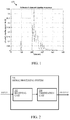
- Fig. 1 shows an example of an estimated channel response.
- the first multipath component of the received signal arrives at around 100 ns such that a distance of around 30 meters between transmitter and receiver can be assumed. More reflections are seen after 200 ns, meaning that these radio paths travel 60 meters or more.
- an earlier multipath component can easily be simulated by an attacker. The simulation of the earlier multipath component becomes more difficult during the payload phase, because data is not or less predictable in that phase.
- the presently disclosed system and method facilitate verifying the content that is modulated on a multipath component.
- a signal processing system comprising: a receiving unit configured to receive at least one signal that comprises a plurality of multipath components; a verification unit configured to correlate at least one multipath component under test with a reference signal derived from one or more of said plurality of multipath components. Furthermore, a corresponding signal processing method is conceived.
- a reference signal may be derived from the strongest multipath components of a signal, and the reference signal may be used for verifying the consistency of information present in the earliest multipath component. This, in turn, enables checking the consistency of the earliest multipath component without demodulating this component.
- the multipath component under test is received earlier in time than the multipath component or components from which the reference signal is derived.
- the reference signal is derived from the strongest multipath component or components.
- the multipath component under test may also be another multipath component; for instance, it is not necessarily the earliest one. For example, one can run a verification on several multipath components, and the earliest (time-of-arrival) one for which the verification test succeeds will be used for a range determination.
- Fig. 2 shows an illustrative embodiment of a signal processing system 200.
- the system 200 comprises a receiving unit 202 operatively coupled to a verification unit 204.
- the receiving unit 202 has an input for receiving an input signal.
- the verification unit 204 has an output for outputting, among others, the result of a verification of the consistency of information present in one or more multipath components under test.
- Fig. 3 shows an illustrative embodiment of a signal processing method 300.
- the method comprises, at 302, receiving, by the receiving unit 202, at least one signal that comprises a plurality of multipath components.
- the method 300 comprises, at 304, correlating, by the verification unit 204, at least one multipath component under test with a reference signal derived from one or more of said plurality of multipath components.
- Fig. 4 shows an illustrative embodiment of a rake receiver 400.
- the receiving unit comprises a rake receiver 400.
- the rake receiver 400 has an input 402, a combiner output 404 and a first path rake finger output 406.
- the rake receiver 400 has a finger that is assigned to the multipath component under test.
- the first path rake finger 406 corresponds to said finger.
- the output of rake finger 406 is coupled to an input of the verification unit (not shown).
- a rake receiver which has, in addition to a conventional rake combiner output, a finger assigned to the multipath component under test.
- the multipath component under test is the earliest multipath component (first path).
- the output of this finger is forwarded separately to the verification unit, in which a consistency check on the content is carried out.
- a separate finger may be assigned to each multipath component under test.
- the outputs of these fingers may also be forwarded to the verification unit.
- the receiving unit may contain other blocks (not shown) that may support the rake receiver 400, such as a carrier/clock synchronization block and a channel estimation block.
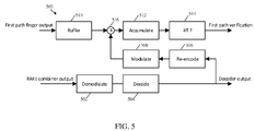
- Fig. 5 shows an illustrative embodiment of a verification unit 500.
- the verification unit 500 comprises a demodulator 502 operatively coupled to a decoder 504, a re-encoder 506 operatively coupled to the decoder 504, and a modulator 508 operatively coupled to the re-encoder 506.
- the verification unit 500 comprises a buffer 510, a multiplier 516, an accumulator 512, and a comparator 514 for determining whether the output of the accumulator 512 is greater than or equal to a threshold "T".
- the combination of the multiplier 516 and accumulator 512 i.e., integrator
- the buffer 510 takes the output of the first path finger (not shown) as an input.
- the demodulator 502 takes the combiner output of the receiving unit (not shown) as an input.
- the comparator 514 outputs a verification result indicative of the result of the correlation process.
- the verification result indicates whether the multipath component under test (embodied by, in this example, the output of the first path finger) is sufficiently similar to the reference signal (embodied by, in this example, the output of the modulator 508).
- the correlator may comprise a complex multiplier in which a received baseband signal of the multipath component under test is multiplied with a complex conjugate of a reference baseband signal.
- the verification unit is configured to derive the reference signal by generating a demodulated signal using one or more of said plurality of multipath components, decoding the demodulated signal, re-encoding the result of said decoding, and modulating the result of said re-encoding.
- the verification unit may forward the demodulated and decoded combiner output of the receiving unit and at the same time verify the consistency of the earliest multipath component without demodulating this component.
- the verification unit is further configured to buffer the multipath component under test before correlating it with the reference signal. Buffering the multipath component under test may compensate for the latency introduced by the demodulator, decoder, re-encoder and modulator. Thus, said buffering enables alignment in time of the multipath component under test and the reference signal.
- Fig. 5 shows that the verification unit 500 contains the demodulator 502 and the decoder 504.
- the demodulator 502 and the decoder 504 may form part of the receiving unit.
- the receiving unit normally already contains a demodulator and a decoder.
- the re-encoder 506 of the verification unit may simply process the output of the receiving unit's decoder.
- the verification unit may receive the reference signal through a side-channel; in that case, the path consisting of blocks 502, 504, 506, 508, as well as block 510 may not be necessary, and consequently the verification unit may only comprise blocks 512, 514, 516, for example.
- the proposed consistency check is a correlation of the information on the earliest multipath component with the re-encoded modulated signal.
- the modulated and decoded output serves after re-encoding and modulation as a reference signal to the signal of the first path finger.
- a buffer for storing the first path finger output may be used for compensating the demodulator, decoder, re-encoder and modulator latency.
- the reference signal may be received through a side channel (not shown) and fed directly to the correlator, more specifically to the multiplier 516. In this way, the re-encoder 506, modulator 508 and buffer 510 may be dispensed with.
- the side-channel may be an encrypted channel.
- the threshold Tfor successful verification should be monotonically dependent on the strength of the tested multipath component.
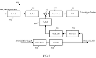
- Fig. 6 shows another illustrative embodiment of a verification unit 600.
- the verification unit 600 comprises a first selector 602 operatively coupled to the buffer 510, and a second selector 604 operatively coupled to the modulator 508.
- the first selector 602 takes the output of the first path finger (not shown) as an input, selects a portion of said output, and provides the selected portion to the buffer 510.
- the second selector 604 takes the output of the modulator 508 as an input, selects a portion of said output, and provides the selected portion as input to the correlation process.
- the second selector 604 may be placed between the decoder 504 and the re-encoder 506.
- the second selector 604 takes the output of the decoder 504 as an input, selects a portion of said output, and provides the selected portion as input to the re-encoder 506. It is noted that the term “portion” refers to a subset of symbols of the multipath component under test and the reference signal, respectively.
- the verification unit is further configured to select a portion of the multipath component under test (embodied by, in this example, a portion of the output of the first path finger) and to select a corresponding portion of the reference signal (embodied by, in this example, a portion of the output of the modulator 508), and to correlate only said portions with each other.
- a further reduction of the buffer size may be achieved, and at the same time a more reliable verification process may be realized.
- the longer the payload the more spreading gain will be obtained and the more robust the earliest path verification can be made. Since some parts of the payload can be predictable, these parts can be excluded from the correlation in order to anticipate manipulation by an attacker.
- the verification unit is further configured to verify if the result of the correlation increases linearly.
- the security of a PKE system may be further increased in the following sense: one can also put constraints on the way the correlation result evolves as a function of time, such that an attacker cannot influence the correlation result by few lucky guesses (i.e., the correlation results should increase linearly).
- the presently disclosed system and method may be applied not only to the earliest multipath component of a signal, but also to other multipath components or to a group of multipath components.
- the first path can be combined with one or more second paths such that the probability of success in case of two genuine paths will increase.
- the verification unit is further configured to correlate a combination of multipath components under test with the reference signal.
- the verification for whether the signal contains the expected information is not done on the individual multipath components under test but on their combined result.
- the verification value correlator value
- the verification value will accordingly be smaller than expected. It is noted that, if these embodiments are used, the probability of a successful attack might also increase. Nevertheless, by selecting a second path of similar strength and by accordingly increasing the threshold for acceptance a trade-off between false acceptance and wrong rejections can be achieved.
- the systems and methods described herein may at least partially be embodied by a computer program or a plurality of computer programs, which may exist in a variety of forms both active and inactive in a single computer system or across multiple computer systems.
- they may exist as software program(s) comprised of program instructions in source code, object code, executable code or other formats for performing some of the steps.
- Any of the above may be embodied on a computer-readable medium, which may include storage devices and signals, in compressed or uncompressed form.
- the term “mobile device” refers to any type of portable electronic device, including a cellular telephone, a Personal Digital Assistant (PDA), smartphone, tablet, etc.
- the term “computer” refers to any electronic device comprising a processor, such as a general-purpose central processing unit (CPU), a specific-purpose processor or a microcontroller.
- CPU central processing unit
- a computer is capable of receiving data (an input), of performing a sequence of predetermined operations thereupon, and of producing thereby a result in the form of information or signals (an output).
- the term “computer” will mean either a processor in particular or more generally a processor in association with an assemblage of interrelated elements contained within a single case or housing.
- processor or “processing unit” refers to a data processing circuit that may be a microprocessor, a co-processor, a microcontroller, a microcomputer, a central processing unit, a field programmable gate array (FPGA), a programmable logic circuit, and/or any circuit that manipulates signals (analog or digital) based on operational instructions that are stored in a memory.
- memory refers to a storage circuit or multiple storage circuits such as read-only memory, random access memory, volatile memory, non-volatile memory, static memory, dynamic memory, Flash memory, cache memory, and/or any circuit that stores digital information.
- a "computer-readable medium” or “storage medium” may be any means that can contain, store, communicate, propagate, or transport a computer program for use by or in connection with the instruction execution system, apparatus, or device.
- the computer-readable medium may be, for example but not limited to, an electronic, magnetic, optical, electromagnetic, infrared, or semiconductor system, apparatus, device, or propagation medium.
- the computer-readable medium may include the following: an electrical connection having one or more wires, a portable computer diskette, a random access memory (RAM), a read-only memory (ROM), an erasable programmable read-only memory (EPROM or Flash memory), an optical fiber, a portable compact disc read-only memory (CDROM), a digital versatile disc (DVD), a Blu-ray disc (BD), and a memory card.
- RAM random access memory
- ROM read-only memory
- EPROM or Flash memory erasable programmable read-only memory
- CDROM compact disc read-only memory
- DVD digital versatile disc
- BD Blu-ray disc
Abstract
Description
- The present disclosure relates to a signal processing system. Furthermore, the present disclosure relates to a corresponding signal processing method and to a corresponding computer program.
- A Passive Keyless Entry (PKE) system is a system that provides a user access to a protected area (e.g., a protected object such as a house, office building or car) without the need of actively using a key or key fob. The only requirement is that the user has the key fob with him or her and that he or she is in the proximity of the protected area. It may be desirable to improve the security of existing PKE systems.
- According to a first aspect of the present disclosure, a signal processing system is provided, comprising: a receiving unit configured to receive at least one signal that comprises a plurality of multipath components; a verification unit configured to correlate at least one multipath component under test with a reference signal derived from one or more of said plurality of multipath components.
- In one or more embodiments, said multipath component under test is received earlier in time than the multipath component or components from which the reference signal is derived.
- In one or more embodiments, the reference signal is derived from the strongest multipath component or components.
- In one or more embodiments, the receiving unit comprises a rake receiver having a finger that is assigned to the multipath component under test, and an output of said finger is coupled to an input of the verification unit.
- In one or more embodiments, the verification unit is configured to derive the reference signal by generating a demodulated signal using one or more of said plurality of multipath components, decoding the demodulated signal, re-encoding the result of said decoding, and modulating the result of said re-encoding.
- In one or more embodiments, the verification unit is further configured to decode and re-encode only a part of the demodulated signal.
- In one or more embodiments, the verification unit is further configured to buffer the multipath component under test before correlating it with the reference signal.
- In one or more embodiments, the verification unit is further configured to select a subset of symbols from the multipath component under test and to select a corresponding a subset of symbols from the reference signal, and to correlate only said subsets with each other.
- In one or more embodiments, the verification unit is further configured to verify if the result of the correlation increases linearly.
- In one or more embodiments, the verification unit is further configured to correlate a combination of multipath components under test with said reference signal.
- In one or more embodiments, the verification unit is further configured to receive the reference signal through a side-channel.
- In one or more embodiments, the verification unit is further configured to select, in a plurality of multipath-component clusters, the earliest multipath component of each cluster, and to verify each cluster by correlating its earliest multipath component with the reference signal.
- In one or more embodiments, a protected object comprises a system of the kind set forth, said object being or comprising a vehicle, an office building, a factory plant, energy plant, or a payment terminal.
- According to a second aspect of the present disclosure, a signal processing method is conceived, comprising: by a receiving unit, receiving at least one signal that comprises a plurality of multipath components; by a verification unit, correlating at least one multipath component under test with a reference signal derived from one or more of said plurality of multipath components.
- According to a third aspect of the present disclosure, a computer program is provided, comprising non-transient instructions which, when executed, carry out or control a method of the kind set forth.
- Embodiments will be described in more detail with reference to the appended drawings, in which:
-
Fig. 1 shows an example of an estimated channel impulse response; -
Fig. 2 shows an illustrative embodiment of a signal processing system; -
Fig. 3 shows an illustrative embodiment of a signal processing method; -
Fig. 4 shows an illustrative embodiment of a receiving unit; -
Fig. 5 shows an illustrative embodiment of a verification unit; -
Fig. 6 shows another illustrative embodiment of a verification unit. - A Passive Keyless Entry (PKE) system is a system that provides a user access to a protected area (e.g., a protected object such as a house, office building or car) without the need of actively using a key or key fob. The only requirement is that the user has the key fob with him or her and that he or she is in the proximity of the protected area. The requirement to be in the proximity of the protected area may be regarded as a location verification problem between a verifier (i.e., the protected area performing a verification process) and a prover (i.e., an authentication token, such as a key fob, providing credentials to the verifier). In accordance with the present disclosure, the location verification is confined to a distance verification problem. The objective of verifying the distance between the verifier and the prover is to rule out attacks in which the challenge and responses are relayed by malicious persons over a large distance between the verifier and the prover. The passive keyless feature of the system implies that such a relay attack may take place without notification of the key fob owner. The proximity check can be carried out with a short range detection mechanism. When a user is in the proximity of the protected area, a detector in the protected area detects the presence of a key fob and can initiate communication with the key fob such that credentials of the key fob can be authenticated by the verifier. However, this approach is vulnerable to so-called relay attacks. Relay attacks have been described, for instance, in the article "Relay Attacks on Passive Keyless Entry and Start Systems in Modern Cars" by A. Francillon, B. Danev and S. Capkun, published at the 2011 Network and Distributed System Security Symposium (NDSS), San Diego, California, 6-9 February 2011.
- A relay attack may be performed as follows. A malicious person can trigger the short-range detection mechanism and relay the initiation of the communication protocol between the protected area and the key fob with, for example, a cable. The initiation of the communication protocol via the relay causes a response of the key fob. The response of the key fob may be relayed by the attacker to the protected area as well, but perhaps the used communication between the key fob and the protected area has a bigger range than what is accepted for the proximity requirement. Since the PKE system is designed on purpose to require no active involvement of the owner of the key fob, the owner will be unaware of the relay attack. Moreover, challenges and responses are relayed between the protected area and the key fob by the attacker without inspection of the messages. Therefore, the attacker does not have to generate the response; he only has to forward the challenges and the response.
- A way to protect systems against relay attacks is to add means for determining the distance between the protected area and the key fob. When the distance is larger than what is accepted by the proximity requirement, access to the protected area is denied. In particular, a distance measurement based on the time-of-flight (TOF) of electromagnetic waves can be used to determine the distance between the protected area and the key fob. An attacker that relays the challenges and responses over a distance that is too large will fail in his attempt to get access to the protected area because the TOF will indicate that the distance is too large. Malicious persons that are willing to do more than just relaying the signals can try to simulate time advancement of the messages, but with random and computationally difficult challenges they cannot successfully simulate a shorter TOF.
- Messages are normally broken down into packets in order to facilitate their transmission. A packet, in turn, contains at least a preamble field, a header field and one or more frames that contain the so-called payload of the packet (i.e., the actual data that are transmitted). A TOF measurement can be done by time stamping the reception of a particular part of a packet. In some communication standards a ranging field may be present in a packet in order to determine the TOF. When such a ranging field contains deterministic values, an attacker can make use of this property and inject a signal in the air that is advanced in time compared to the authentic communication between the protected area and the key fob, such that the TOF determination will lead to a smaller value and the corresponding range calculation will conclude with a smaller distance determination. A way to mitigate this security flaw is to use ranging fields with a random but earlier agreed ranging marker. However, this approach requires extra means to come to an agreement on the ranging marker value. For instance, the random marker field can be agreed upon using additional messages; alternatively, ranging markers can be generated synchronously by a transmitter and a receiver. In the IEEE802.15.4a standard the packet format has no ranging field and it is suggested to use for example the boundary between the Start-Of-Frame Delimiter (SOFD) and the header field. However, the contents of the SOFD field are fixed and can therefore easily be inserted in the message exchange by an attacker in order to realize a shorter TOF. Moreover, a known preamble is prepended to the SOFD; as a result, an attacker can already start to advance the TOF measurement during the acquisition phase.
- A TOF measurement is often done by correlating a received signal with a sequence that is present in the transmitted signal and that one wants to use for determining the time-of-arrival of the message. This sequence might be the sequence in the ranging field or the SOFD sequence. Correlation refers to a process of computing a correlation coefficient that shows the degree of similarity between the received signal and said sequence. In case of multipath communication, several correlation hits will occur, but for the TOF determination the earliest multipath component is relevant, which normally is the Line-of-Sight (LOS) component. Such a LOS component might be weaker than multipath components that are later in the channel impulse response. For instance, the radio path between the protected area and the key fob might be obstructed by the body of a person (e.g. the user) such that the propagation of the direct path is attenuated and might be weaker than a radio wave that travelled a longer path.
- It is noted that the TOF determination is closely related to the estimation of the channel impulse response. For the TOF determination one is interested in the earliest arrival of signal energy while for the channel impulse response estimation one is interested in all multipath components that can contribute to successful decoding of the whole message. For example, in a rake receiver, the contributions of the strongest multipath components can be coherently combined such that the signal-to-noise ratio (SNR) at the symbol decision device is maximized. With a predictable preamble and ranging marker (or SOFD), the time arrival of the earliest multipath component can easily be manipulated by an attacker by transmission of a time advanced version of the preamble and ranging marker. However, an attacker cannot do this for the rest of the packet in case of an unpredictable payload (e.g., challenge and/or response).
-
Fig. 1 shows an example of an estimated channel response. The first multipath component of the received signal arrives at around 100 ns such that a distance of around 30 meters between transmitter and receiver can be assumed. More reflections are seen after 200 ns, meaning that these radio paths travel 60 meters or more. However, as discussed before, with predictable signals an earlier multipath component can easily be simulated by an attacker. The simulation of the earlier multipath component becomes more difficult during the payload phase, because data is not or less predictable in that phase. The question arises whether the earliest multipath component is a genuine radio wave or a simulated one. The presently disclosed system and method facilitate verifying the content that is modulated on a multipath component. - The following cases can be distinguished:
- A system can base its access decision only on the TOF determination that is done based on the preamble and the ranging field. The system will not verify whether the earliest multipath component is still present during the rest of the packet. In this case, the attacker does not have to simulate the earliest multipath component during the rest of the packet.
- When in the system the presence of the earliest multipath component is checked during the payload part of the packet the attacker has to follow another strategy. In particular, he has to simulate the earliest multipath component also during the payload phase, but he has the problem that he does not know which information to modulate during the payload phase. A strategy that can be followed by the attacker is to give the earliest multipath component an amplitude that is just high enough to be detected during the TOF measurement in preamble and SOFD, but that is not high enough to allow demodulation during the payload phase or to negatively influence the multipath combiner output during the payload. Since the attacker cannot fully predict the payload, he has to modulate the simulated multipath component with random data. In this way the system will sense the presence of signal energy at the arrival time of the presumed earliest multipath component but it cannot check whether the content of the earliest multipath component is authentic or random. For accepting a TOF determination the system can follow two procedures:
- 1) It can accept a TOF determination only when it is able to demodulate the earliest multipath component and check its consistency with the content of the other multipath components. The disadvantage of this method is that the earliest multipath component should be sufficiently strong; otherwise the ranging measurement will be discarded. This leads to an asymmetry in communication robustness versus ranging robustness. Since for communication one wants to use the contribution of the strongest multipath components, communication is more robust than ranging which is based upon the contribution of the earliest multipath component. Moreover, a separate demodulation of the earliest multipath component requires duplication of modulation and decoding resources.
- 2) The system may only check the presence of the earliest multipath component, but in that case the attacker has an easy game. The attacker has to simulate the presence of the earliest multipath component, but he does not have to care about the information to modulate on this multipath component.
- The presently disclosed system and method facilitate checking the consistency of the earliest multipath component without demodulating this component. As discussed above, checking the consistency of the content of the earliest multipath component by demodulating the content separately from the other multipath components might be difficult and expensive. The earliest multipath component might be very weak and for communication robustness it is preferred to combine the information of the strongest multipath components. Therefore, in accordance with the present disclosure, a signal processing system is provided, comprising: a receiving unit configured to receive at least one signal that comprises a plurality of multipath components; a verification unit configured to correlate at least one multipath component under test with a reference signal derived from one or more of said plurality of multipath components. Furthermore, a corresponding signal processing method is conceived. Using the presently disclosed system and method, the following practical and efficient consistency check may for example be realized: a reference signal may be derived from the strongest multipath components of a signal, and the reference signal may be used for verifying the consistency of information present in the earliest multipath component. This, in turn, enables checking the consistency of the earliest multipath component without demodulating this component.
- Thus, in one or more embodiments, the multipath component under test is received earlier in time than the multipath component or components from which the reference signal is derived. Furthermore, in one or more embodiments, the reference signal is derived from the strongest multipath component or components. However, the multipath component under test may also be another multipath component; for instance, it is not necessarily the earliest one. For example, one can run a verification on several multipath components, and the earliest (time-of-arrival) one for which the verification test succeeds will be used for a range determination.
-
Fig. 2 shows an illustrative embodiment of asignal processing system 200. Thesystem 200 comprises a receivingunit 202 operatively coupled to averification unit 204. The receivingunit 202 has an input for receiving an input signal. Theverification unit 204 has an output for outputting, among others, the result of a verification of the consistency of information present in one or more multipath components under test. -
Fig. 3 shows an illustrative embodiment of asignal processing method 300. The method comprises, at 302, receiving, by the receivingunit 202, at least one signal that comprises a plurality of multipath components. Furthermore, themethod 300 comprises, at 304, correlating, by theverification unit 204, at least one multipath component under test with a reference signal derived from one or more of said plurality of multipath components. -
Fig. 4 shows an illustrative embodiment of arake receiver 400. In this non-limiting example, the receiving unit comprises arake receiver 400. It is noted that the presently disclosed system and method may also employ other types of receivers capable of handling multipath components, such as channel matched filters. Therake receiver 400 has aninput 402, acombiner output 404 and a first path rakefinger output 406. In a practical and efficient implementation, therake receiver 400 has a finger that is assigned to the multipath component under test. In this example, the first path rakefinger 406 corresponds to said finger. The output ofrake finger 406 is coupled to an input of the verification unit (not shown). In particular, a rake receiver is shown, which has, in addition to a conventional rake combiner output, a finger assigned to the multipath component under test. In this example, the multipath component under test is the earliest multipath component (first path). The output of this finger is forwarded separately to the verification unit, in which a consistency check on the content is carried out. In case there are two or more multipath components under test, then a separate finger may be assigned to each multipath component under test. In that case, the outputs of these fingers may also be forwarded to the verification unit. It is noted that, in addition to therake receiver 400, the receiving unit may contain other blocks (not shown) that may support therake receiver 400, such as a carrier/clock synchronization block and a channel estimation block. -
Fig. 5 shows an illustrative embodiment of averification unit 500. Theverification unit 500 comprises ademodulator 502 operatively coupled to adecoder 504, a re-encoder 506 operatively coupled to thedecoder 504, and amodulator 508 operatively coupled to the re-encoder 506. Furthermore, theverification unit 500 comprises abuffer 510, amultiplier 516, anaccumulator 512, and acomparator 514 for determining whether the output of theaccumulator 512 is greater than or equal to a threshold "T". The combination of themultiplier 516 and accumulator 512 (i.e., integrator) may be referred to as a correlator. In operation, thebuffer 510 takes the output of the first path finger (not shown) as an input. Furthermore, thedemodulator 502 takes the combiner output of the receiving unit (not shown) as an input. Furthermore, thecomparator 514 outputs a verification result indicative of the result of the correlation process. In particular, the verification result indicates whether the multipath component under test (embodied by, in this example, the output of the first path finger) is sufficiently similar to the reference signal (embodied by, in this example, the output of the modulator 508). It is noted that the correlator may comprise a complex multiplier in which a received baseband signal of the multipath component under test is multiplied with a complex conjugate of a reference baseband signal. - Thus, in one or more embodiments, the verification unit is configured to derive the reference signal by generating a demodulated signal using one or more of said plurality of multipath components, decoding the demodulated signal, re-encoding the result of said decoding, and modulating the result of said re-encoding. This results in a practical and efficient implementation. More specifically, the verification unit may forward the demodulated and decoded combiner output of the receiving unit and at the same time verify the consistency of the earliest multipath component without demodulating this component. Furthermore, in one or more embodiments, the verification unit is further configured to buffer the multipath component under test before correlating it with the reference signal. Buffering the multipath component under test may compensate for the latency introduced by the demodulator, decoder, re-encoder and modulator. Thus, said buffering enables alignment in time of the multipath component under test and the reference signal.
-
Fig. 5 shows that theverification unit 500 contains thedemodulator 502 and thedecoder 504. However, in other embodiments, thedemodulator 502 and thedecoder 504 may form part of the receiving unit. It is noted that the receiving unit normally already contains a demodulator and a decoder. Thus, in a practical and efficient implementation, there-encoder 506 of the verification unit may simply process the output of the receiving unit's decoder. Furthermore, in other embodiments, the verification unit may receive the reference signal through a side-channel; in that case, the path consisting ofblocks block 510 may not be necessary, and consequently the verification unit may only compriseblocks - Thus, in this non-limiting example, the proposed consistency check is a correlation of the information on the earliest multipath component with the re-encoded modulated signal. The modulated and decoded output serves after re-encoding and modulation as a reference signal to the signal of the first path finger. A buffer for storing the first path finger output may be used for compensating the demodulator, decoder, re-encoder and modulator latency. Alternatively, the reference signal may be received through a side channel (not shown) and fed directly to the correlator, more specifically to the
multiplier 516. In this way, the re-encoder 506,modulator 508 and buffer 510 may be dispensed with. The side-channel may be an encrypted channel. When the information on the earliest multipath component is authentic, the correlation value will increase fairly linearly. In case an attacker is simulating the earliest multipath component with random data, the correlation result will not increase linearly, but it will randomly move around zero. In this implementation, which represents a non-limiting example, the threshold Tfor successful verification should be monotonically dependent on the strength of the tested multipath component. - Furthermore, in one or more embodiments, the verification unit is further configured to decode and re-encode only a part of the demodulated signal. Thereby, a trade-off may be achieved between the size of the buffer and the performance of the verification process. A trade-off between the buffer size and the verification performance can be achieved by skipping parts of the decoder and re-encoder. For instance, according to the standard IEEE802.15.4a a concatenation of a convolutional code and a Reed-Solomon (RS) code is used. One can for example only re-encode and modulate the output of the Viterbi decoder (i.e., only the decoded convolutional code), so that the latency of the RS decoder and encoder in the verification path may be avoided. In particular, this leads to a lower latency in the re-encoding path and therefore a smaller buffer is needed for the first path finger output.
-
Fig. 6 shows another illustrative embodiment of averification unit 600. In addition to the components shown inFig. 5 , theverification unit 600 comprises afirst selector 602 operatively coupled to thebuffer 510, and asecond selector 604 operatively coupled to themodulator 508. In operation, thefirst selector 602 takes the output of the first path finger (not shown) as an input, selects a portion of said output, and provides the selected portion to thebuffer 510. Furthermore, thesecond selector 604 takes the output of themodulator 508 as an input, selects a portion of said output, and provides the selected portion as input to the correlation process. Alternatively, thesecond selector 604 may be placed between thedecoder 504 and the re-encoder 506. In that case, thesecond selector 604 takes the output of thedecoder 504 as an input, selects a portion of said output, and provides the selected portion as input to the re-encoder 506. It is noted that the term "portion" refers to a subset of symbols of the multipath component under test and the reference signal, respectively. - Thus, in one or more embodiments, the verification unit is further configured to select a portion of the multipath component under test (embodied by, in this example, a portion of the output of the first path finger) and to select a corresponding portion of the reference signal (embodied by, in this example, a portion of the output of the modulator 508), and to correlate only said portions with each other. Thereby, a further reduction of the buffer size may be achieved, and at the same time a more reliable verification process may be realized. In general, the longer the payload, the more spreading gain will be obtained and the more robust the earliest path verification can be made. Since some parts of the payload can be predictable, these parts can be excluded from the correlation in order to anticipate manipulation by an attacker. The attacker can for example boost the predictable part such that the accumulator value will grow faster. In accordance with the present disclosure, however, the predictable part of the payload may be excluded from the verification process. That is to say, by verifying only a part of the signal on the first path finger output, a reduction of buffer size may be accomplished, and if predictable information can be excluded from the verification process, the verification may become more reliable.
- Furthermore, in one or more embodiments, the verification unit is further configured to verify if the result of the correlation increases linearly. Thereby, the security of a PKE system may be further increased in the following sense: one can also put constraints on the way the correlation result evolves as a function of time, such that an attacker cannot influence the correlation result by few lucky guesses (i.e., the correlation results should increase linearly).
- It is noted that the presently disclosed system and method may be applied not only to the earliest multipath component of a signal, but also to other multipath components or to a group of multipath components. For example, one can perform a verification on several multipath components, and the earliest (time-of-arrival) one for which the verification test succeeds may be used for a range determination. In another possible implementation the first path can be combined with one or more second paths such that the probability of success in case of two genuine paths will increase. In other words, in one or more embodiments, the verification unit is further configured to correlate a combination of multipath components under test with the reference signal. According to these embodiments, one can, in a similar way as is done for the main signal (i.e., combining the multipath components in a rake receiver, as shown in
Fig. 4 ), also make a combined signal for two or more multipath components under test. After combining the two or more multipath components under test in a smaller rake configuration, the verification for whether the signal contains the expected information is not done on the individual multipath components under test but on their combined result. In case the combined multipath components under test are all genuine, the verification value (correlator value) will be higher and the probability that a time-of-arrival measurement will be discarded due to a non-conclusive verification value will be smaller. In case not all multipath components are genuine, the verification value will accordingly be smaller than expected. It is noted that, if these embodiments are used, the probability of a successful attack might also increase. Nevertheless, by selecting a second path of similar strength and by accordingly increasing the threshold for acceptance a trade-off between false acceptance and wrong rejections can be achieved. - Furthermore, in one or more embodiments, the verification unit is further configured to select, in a plurality of multipath-component clusters, the earliest multipath component of each cluster, and to verify each cluster by correlating its earliest multipath component with the reference signal. In particular, a channel estimation typically yields clusters of multipath components. In accordance with these embodiments, the verification (i.e., correlation) may be performed only on the earliest (i.e., first) multipath component of the first cluster. Then, if the verification result indicates this multipath component is not a genuine one (e.g., if the correlation value does not increase linearly as expected), then the whole cluster to which said component belongs may be regarded as not genuine. In other words, all other multipath components of the same cluster are regarded as not genuine. Subsequently, the earliest (i.e., first) multipath component of the next cluster may be verified. Again, if the verification result indicates this multipath component is not a genuine one, then the whole cluster to which said component belongs may be regarded as not genuine. This process may be repeated until a multipath component yields a positive verification result; this multipath component may then be used for a range determination. These embodiments may result in a more efficient use of resources, because only one correlation needs to be performed for a whole cluster of multipath components. That is to say, each cluster may still be tested, but the implementation complexity may be reduced. It is noted that, although this process has been described as a sequential process, it is also possible that the earliest multipath components of said clusters are tested in parallel.
- The systems and methods described herein may at least partially be embodied by a computer program or a plurality of computer programs, which may exist in a variety of forms both active and inactive in a single computer system or across multiple computer systems. For example, they may exist as software program(s) comprised of program instructions in source code, object code, executable code or other formats for performing some of the steps. Any of the above may be embodied on a computer-readable medium, which may include storage devices and signals, in compressed or uncompressed form.
- As used herein, the term "mobile device" refers to any type of portable electronic device, including a cellular telephone, a Personal Digital Assistant (PDA), smartphone, tablet, etc. Furthermore, the term "computer" refers to any electronic device comprising a processor, such as a general-purpose central processing unit (CPU), a specific-purpose processor or a microcontroller. A computer is capable of receiving data (an input), of performing a sequence of predetermined operations thereupon, and of producing thereby a result in the form of information or signals (an output). Depending on the context, the term "computer" will mean either a processor in particular or more generally a processor in association with an assemblage of interrelated elements contained within a single case or housing.
- The term "processor" or "processing unit" refers to a data processing circuit that may be a microprocessor, a co-processor, a microcontroller, a microcomputer, a central processing unit, a field programmable gate array (FPGA), a programmable logic circuit, and/or any circuit that manipulates signals (analog or digital) based on operational instructions that are stored in a memory. The term "memory" refers to a storage circuit or multiple storage circuits such as read-only memory, random access memory, volatile memory, non-volatile memory, static memory, dynamic memory, Flash memory, cache memory, and/or any circuit that stores digital information.
- As used herein, a "computer-readable medium" or "storage medium" may be any means that can contain, store, communicate, propagate, or transport a computer program for use by or in connection with the instruction execution system, apparatus, or device. The computer-readable medium may be, for example but not limited to, an electronic, magnetic, optical, electromagnetic, infrared, or semiconductor system, apparatus, device, or propagation medium. More specific examples (non-exhaustive list) of the computer-readable medium may include the following: an electrical connection having one or more wires, a portable computer diskette, a random access memory (RAM), a read-only memory (ROM), an erasable programmable read-only memory (EPROM or Flash memory), an optical fiber, a portable compact disc read-only memory (CDROM), a digital versatile disc (DVD), a Blu-ray disc (BD), and a memory card.
- It is noted that the embodiments above have been described with reference to different subject-matters. In particular, some embodiments may have been described with reference to method-type claims whereas other embodiments may have been described with reference to apparatus-type claims. However, a person skilled in the art will gather from the above that, unless otherwise indicated, in addition to any combination of features belonging to one type of subject-matter also any combination of features relating to different subject-matters, in particular a combination of features of the method-type claims and features of the apparatus-type claims, is considered to be disclosed with this document.
- Furthermore, it is noted that the drawings are schematic. In different drawings, similar or identical elements are provided with the same reference signs. Furthermore, it is noted that in an effort to provide a concise description of the illustrative embodiments, implementation details which fall into the customary practice of the skilled person may not have been described. It should be appreciated that in the development of any such implementation, as in any engineering or design project, numerous implementation-specific decisions must be made in order to achieve the developers' specific goals, such as compliance with system-related and business-related constraints, which may vary from one implementation to another. Moreover, it should be appreciated that such a development effort might be complex and time consuming, but would nevertheless be a routine undertaking of design, fabrication, and manufacture for those of ordinary skill.
- Finally, it is noted that the skilled person will be able to design many alternative embodiments without departing from the scope of the appended claims. In the claims, any reference sign placed between parentheses shall not be construed as limiting the claim. The word "comprise(s)" or "comprising" does not exclude the presence of elements or steps other than those listed in a claim. The word "a" or "an" preceding an element does not exclude the presence of a plurality of such elements. Measures recited in the claims may be implemented by means of hardware comprising several distinct elements and/or by means of a suitably programmed processor. In a device claim enumerating several means, several of these means may be embodied by one and the same item of hardware. The mere fact that certain measures are recited in mutually different dependent claims does not indicate that a combination of these measures cannot be used to advantage.
-
- 100
- estimated channel impulse response
- 200
- signal processing system
- 202
- receiving unit
- 204
- verification unit
- 300
- signal processing method
- 302
- receive signal comprising multipath components
- 304
- correlate multipath component under test with reference signal
- 400
- rake receiver
- 402
- input of rake receiver
- 404
- output of rake receiver
- 406
- first path finger
- 500
- verification unit
- 502
- demodulate
- 504
- decode
- 506
- re-encode
- 508
- modulate
- 510
- buffer
- 512
- accumulate
- 514
- compare
- 516
- multiply
- 600
- verification unit
- 602
- select
- 604
- select
Claims (15)
- A signal processing system comprising:a receiving unit configured to receive at least one signal that comprises a plurality of multipath components;a verification unit configured to correlate at least one multipath component under test with a reference signal derived from one or more of said plurality of multipath components.
- A system as claimed in claim 1, wherein said multipath component under test is received earlier in time than the multipath component or components from which the reference signal is derived.
- A system as claimed in any preceding claim, wherein the reference signal is derived from the strongest multipath component or components.
- A system as claimed in any preceding claim, wherein the receiving unit comprises a rake receiver, wherein said rake receiver has a finger that is assigned to the multipath component under test, and wherein an output of said finger is coupled to an input of the verification unit.
- A system as claimed in any preceding claim, wherein the verification unit is configured to derive the reference signal by generating a demodulated signal using one or more of said plurality of multipath components, decoding the demodulated signal, re-encoding the result of said decoding, and modulating the result of said re-encoding.
- A system as claimed in claim 5, wherein the verification unit is further configured to decode and re-encode only a part of the demodulated signal.
- A system as claimed in any preceding claim, wherein the verification unit is further configured to buffer the multipath component or components under test before correlating it with the reference signal.
- A system as claimed in any preceding claim, wherein the verification unit is further configured to select a subset of symbols from the multipath component under test and to select a corresponding subset of symbols from the reference signal, and to correlate only said subsets with each other.
- A system as claimed in any preceding claim, wherein the verification unit is further configured to verify if the result of the correlation increases linearly.
- A system as claimed in any preceding claim, wherein the verification unit is further configured to correlate a combination of multipath components under test with said reference signal.
- A system as claimed in any preceding claim, wherein the verification unit is further configured to receive the reference signal through a side-channel.
- A system as claimed in any preceding claim, wherein the verification unit is further configured to select, in a plurality of multipath-component clusters, the earliest multipath component of each cluster, and to verify each cluster by correlating its earliest multipath component with the reference signal.
- A protected object comprising a system as claimed in any preceding claim, said object being or comprising a vehicle, an office building, a factory plant, energy plant, or a payment terminal.
- A signal processing method comprising:by a receiving unit, receiving at least one signal that comprises a plurality of multipath components;by a verification unit, correlating at least one multipath component under test with a reference signal derived from one or more of said plurality of multipath components.
- A computer program comprising non-transient instructions which, when executed, carry out or control a method as claimed in claim 14.
Priority Applications (3)
| Application Number | Priority Date | Filing Date | Title |
|---|---|---|---|
| EP16173467.8A EP3255805B1 (en) | 2016-06-08 | 2016-06-08 | Signal processing system and method |
| US15/605,721 US9916708B2 (en) | 2016-06-08 | 2017-05-25 | Signal processing system and method |
| CN201710387480.5A CN107592122B (en) | 2016-06-08 | 2017-05-26 | Signal processing system and method |
Applications Claiming Priority (1)
| Application Number | Priority Date | Filing Date | Title |
|---|---|---|---|
| EP16173467.8A EP3255805B1 (en) | 2016-06-08 | 2016-06-08 | Signal processing system and method |
Publications (2)
| Publication Number | Publication Date |
|---|---|
| EP3255805A1 true EP3255805A1 (en) | 2017-12-13 |
| EP3255805B1 EP3255805B1 (en) | 2020-09-02 |
Family
ID=56131342
Family Applications (1)
| Application Number | Title | Priority Date | Filing Date |
|---|---|---|---|
| EP16173467.8A Active EP3255805B1 (en) | 2016-06-08 | 2016-06-08 | Signal processing system and method |
Country Status (3)
| Country | Link |
|---|---|
| US (1) | US9916708B2 (en) |
| EP (1) | EP3255805B1 (en) |
| CN (1) | CN107592122B (en) |
Cited By (1)
| Publication number | Priority date | Publication date | Assignee | Title |
|---|---|---|---|---|
| WO2021018702A1 (en) * | 2019-07-30 | 2021-02-04 | Continental Automotive Gmbh | Control device for a motor vehicle access or locating system and method |
Families Citing this family (1)
| Publication number | Priority date | Publication date | Assignee | Title |
|---|---|---|---|---|
| CN106452629B (en) * | 2016-11-07 | 2019-03-15 | 北京交通大学 | A kind of radio channel multi-path cluster-dividing method based on core power density |
Citations (3)
| Publication number | Priority date | Publication date | Assignee | Title |
|---|---|---|---|---|
| US20050078741A1 (en) * | 2003-08-09 | 2005-04-14 | Hun-Geun Song | Apparatus and method for detecting a timing error in a mobile communication system |
| EP1746739A2 (en) * | 2005-07-22 | 2007-01-24 | Industrial Technology Research Institute | Apparatus for path selection and signal processing in wireless communications system |
| EP1845628A1 (en) * | 2005-01-18 | 2007-10-17 | NTT DoCoMo Inc. | Mobile communication terminal, and multipath interference eliminating method |
Family Cites Families (12)
| Publication number | Priority date | Publication date | Assignee | Title |
|---|---|---|---|---|
| US7184457B2 (en) * | 2000-02-28 | 2007-02-27 | Texas Instruments Incorporated | Spread spectrum path estimation |
| GB0022634D0 (en) * | 2000-09-15 | 2000-11-01 | Koninkl Philips Electronics Nv | Secondary station and method of operating the station |
| US6618434B2 (en) * | 2001-05-31 | 2003-09-09 | Quicksilver Technology, Inc. | Adaptive, multimode rake receiver for dynamic search and multipath reception |
| US7010017B2 (en) * | 2002-01-30 | 2006-03-07 | Qualcomm Inc. | Receiver noise estimation |
| GB0410617D0 (en) * | 2004-05-12 | 2004-06-16 | Ttp Communications Ltd | Path searching |
| US7480356B2 (en) * | 2004-12-08 | 2009-01-20 | Telefonaktiebolaget L M Ericsson (Publ) | Method of and system for path selection in rich multipath conditions |
| US8126098B2 (en) * | 2006-09-12 | 2012-02-28 | Marvell World Trade Ltd. | Multi-rake receiver |
| US9125168B2 (en) * | 2013-01-23 | 2015-09-01 | Intel Corporation | Polled time-of-flight response |
| JP2016511403A (en) * | 2013-02-25 | 2016-04-14 | コーニンクレッカ フィリップス エヌ ヴェKoninklijke Philips N.V. | Autonomous direction finding using differential angle of arrival |
| US8930045B2 (en) * | 2013-05-01 | 2015-01-06 | Delphi Technologies, Inc. | Relay attack prevention for passive entry passive start (PEPS) vehicle security systems |
| US9114720B2 (en) * | 2013-07-11 | 2015-08-25 | Delphi Technologies, Inc. | Vehicle positioning system for wireless charging stations |
| US9613475B2 (en) | 2015-05-27 | 2017-04-04 | Nxp B.V. | Communications with interaction detection |
-
2016
- 2016-06-08 EP EP16173467.8A patent/EP3255805B1/en active Active
-
2017
- 2017-05-25 US US15/605,721 patent/US9916708B2/en active Active
- 2017-05-26 CN CN201710387480.5A patent/CN107592122B/en active Active
Patent Citations (3)
| Publication number | Priority date | Publication date | Assignee | Title |
|---|---|---|---|---|
| US20050078741A1 (en) * | 2003-08-09 | 2005-04-14 | Hun-Geun Song | Apparatus and method for detecting a timing error in a mobile communication system |
| EP1845628A1 (en) * | 2005-01-18 | 2007-10-17 | NTT DoCoMo Inc. | Mobile communication terminal, and multipath interference eliminating method |
| EP1746739A2 (en) * | 2005-07-22 | 2007-01-24 | Industrial Technology Research Institute | Apparatus for path selection and signal processing in wireless communications system |
Non-Patent Citations (2)
| Title |
|---|
| A. FRANCILLON; B. DANEV; S. CAPKUN: "Relay Attacks on Passive Keyless Entry and Start Systems in Modern Cars", THE 2011 NETWORK AND DISTRIBUTED SYSTEM SECURITY SYMPOSIUM (NDSS, 6 February 2011 (2011-02-06) |
| MARCIN POTURALSKI ET AL: "On Secure and Precise IR-UWB Ranging", IEEE TRANSACTIONS ON WIRELESS COMMUNICATIONS, IEEE SERVICE CENTER, PISCATAWAY, NJ, US, vol. 11, no. 3, 1 March 2012 (2012-03-01), pages 1087 - 1099, XP011433100, ISSN: 1536-1276, DOI: 10.1109/TWC.2012.011812.110483 * |
Cited By (1)
| Publication number | Priority date | Publication date | Assignee | Title |
|---|---|---|---|---|
| WO2021018702A1 (en) * | 2019-07-30 | 2021-02-04 | Continental Automotive Gmbh | Control device for a motor vehicle access or locating system and method |
Also Published As
| Publication number | Publication date |
|---|---|
| EP3255805B1 (en) | 2020-09-02 |
| CN107592122B (en) | 2020-12-29 |
| US9916708B2 (en) | 2018-03-13 |
| CN107592122A (en) | 2018-01-16 |
| US20170358158A1 (en) | 2017-12-14 |
Similar Documents
| Publication | Publication Date | Title |
|---|---|---|
| Spuhler et al. | Detection of reactive jamming in DSSS-based wireless communications | |
| Munilla et al. | Distance bounding protocols for RFID enhanced by using void‐challenges and analysis in noisy channels | |
| CN104199654B (en) | The call method and device of open platform | |
| US9613475B2 (en) | Communications with interaction detection | |
| CN114223179B (en) | Safe ultra wideband ranging | |
| WO2017121452A1 (en) | Method, device and system for secure distance measurement | |
| US11009608B2 (en) | GNSS authentication method | |
| Leu et al. | Message time of arrival codes: A fundamental primitive for secure distance measurement | |
| US9916708B2 (en) | Signal processing system and method | |
| Caparra et al. | Feasibility and limitations of self-spoofing attacks on GNSS signals with message authentication | |
| CN108206795B (en) | Blind authentication method and system of frequency selective fading channel based on confidence transfer | |
| Compagno et al. | Modeling enlargement attacks against UWB distance bounding protocols | |
| Pagnin et al. | HB+ DB: Distance bounding meets human based authentication | |
| CN113447959A (en) | GNSS deception jamming detection method based on Doppler frequency and related device | |
| Ran et al. | Physical layer authentication scheme with channel based tag padding sequence | |
| Munilla et al. | Attacks on a distance bounding protocol | |
| Wesson | Secure navigation and timing without local storage of secret keys | |
| CN111669360B (en) | Method, device and system for measuring safe distance | |
| EP1869819A1 (en) | Method and system for detecting messages in the presence of noise | |
| US6636494B1 (en) | Method of resolving physical layer collisions in a random access protocol an a corresponding receiver | |
| Hussain et al. | TIGHT: A cross-layer RF distance bounding realization for passive wireless devices | |
| Pagnin et al. | HB+ DB, mitigating man-in-the-middle attacks against hb+ with distance bounding | |
| Jannati et al. | Achieving an appropriate security level for distance bounding protocols over a noisy channel | |
| Rajmohan et al. | An Analysis and Efficient Approach to Protect CR Networks. | |
| KR20240034023A (en) | Device and method of detecting for hrp uwb ranging against distance reduction attacks |
Legal Events
| Date | Code | Title | Description |
|---|---|---|---|
| PUAI | Public reference made under article 153(3) epc to a published international application that has entered the european phase |
Free format text: ORIGINAL CODE: 0009012 |
|
| STAA | Information on the status of an ep patent application or granted ep patent |
Free format text: STATUS: THE APPLICATION HAS BEEN PUBLISHED |
|
| AK | Designated contracting states |
Kind code of ref document: A1 Designated state(s): AL AT BE BG CH CY CZ DE DK EE ES FI FR GB GR HR HU IE IS IT LI LT LU LV MC MK MT NL NO PL PT RO RS SE SI SK SM TR |
|
| AX | Request for extension of the european patent |
Extension state: BA ME |
|
| STAA | Information on the status of an ep patent application or granted ep patent |
Free format text: STATUS: REQUEST FOR EXAMINATION WAS MADE |
|
| 17P | Request for examination filed |
Effective date: 20180613 |
|
| RBV | Designated contracting states (corrected) |
Designated state(s): AL AT BE BG CH CY CZ DE DK EE ES FI FR GB GR HR HU IE IS IT LI LT LU LV MC MK MT NL NO PL PT RO RS SE SI SK SM TR |
|
| GRAP | Despatch of communication of intention to grant a patent |
Free format text: ORIGINAL CODE: EPIDOSNIGR1 |
|
| STAA | Information on the status of an ep patent application or granted ep patent |
Free format text: STATUS: GRANT OF PATENT IS INTENDED |
|
| INTG | Intention to grant announced |
Effective date: 20200217 |
|
| GRAS | Grant fee paid |
Free format text: ORIGINAL CODE: EPIDOSNIGR3 |
|
| GRAA | (expected) grant |
Free format text: ORIGINAL CODE: 0009210 |
|
| STAA | Information on the status of an ep patent application or granted ep patent |
Free format text: STATUS: THE PATENT HAS BEEN GRANTED |
|
| AK | Designated contracting states |
Kind code of ref document: B1 Designated state(s): AL AT BE BG CH CY CZ DE DK EE ES FI FR GB GR HR HU IE IS IT LI LT LU LV MC MK MT NL NO PL PT RO RS SE SI SK SM TR |
|
| REG | Reference to a national code |
Ref country code: GB Ref legal event code: FG4D |
|
| REG | Reference to a national code |
Ref country code: AT Ref legal event code: REF Ref document number: 1310000 Country of ref document: AT Kind code of ref document: T Effective date: 20200915 Ref country code: CH Ref legal event code: EP |
|
| REG | Reference to a national code |
Ref country code: DE Ref legal event code: R096 Ref document number: 602016043054 Country of ref document: DE |
|
| REG | Reference to a national code |
Ref country code: IE Ref legal event code: FG4D |
|
| REG | Reference to a national code |
Ref country code: LT Ref legal event code: MG4D |
|
| PG25 | Lapsed in a contracting state [announced via postgrant information from national office to epo] |
Ref country code: FI Free format text: LAPSE BECAUSE OF FAILURE TO SUBMIT A TRANSLATION OF THE DESCRIPTION OR TO PAY THE FEE WITHIN THE PRESCRIBED TIME-LIMIT Effective date: 20200902 Ref country code: GR Free format text: LAPSE BECAUSE OF FAILURE TO SUBMIT A TRANSLATION OF THE DESCRIPTION OR TO PAY THE FEE WITHIN THE PRESCRIBED TIME-LIMIT Effective date: 20201203 Ref country code: NO Free format text: LAPSE BECAUSE OF FAILURE TO SUBMIT A TRANSLATION OF THE DESCRIPTION OR TO PAY THE FEE WITHIN THE PRESCRIBED TIME-LIMIT Effective date: 20201202 Ref country code: SE Free format text: LAPSE BECAUSE OF FAILURE TO SUBMIT A TRANSLATION OF THE DESCRIPTION OR TO PAY THE FEE WITHIN THE PRESCRIBED TIME-LIMIT Effective date: 20200902 Ref country code: BG Free format text: LAPSE BECAUSE OF FAILURE TO SUBMIT A TRANSLATION OF THE DESCRIPTION OR TO PAY THE FEE WITHIN THE PRESCRIBED TIME-LIMIT Effective date: 20201202 Ref country code: HR Free format text: LAPSE BECAUSE OF FAILURE TO SUBMIT A TRANSLATION OF THE DESCRIPTION OR TO PAY THE FEE WITHIN THE PRESCRIBED TIME-LIMIT Effective date: 20200902 Ref country code: LT Free format text: LAPSE BECAUSE OF FAILURE TO SUBMIT A TRANSLATION OF THE DESCRIPTION OR TO PAY THE FEE WITHIN THE PRESCRIBED TIME-LIMIT Effective date: 20200902 |
|
| REG | Reference to a national code |
Ref country code: NL Ref legal event code: MP Effective date: 20200902 |
|
| REG | Reference to a national code |
Ref country code: AT Ref legal event code: MK05 Ref document number: 1310000 Country of ref document: AT Kind code of ref document: T Effective date: 20200902 |
|
| PG25 | Lapsed in a contracting state [announced via postgrant information from national office to epo] |
Ref country code: PL Free format text: LAPSE BECAUSE OF FAILURE TO SUBMIT A TRANSLATION OF THE DESCRIPTION OR TO PAY THE FEE WITHIN THE PRESCRIBED TIME-LIMIT Effective date: 20200902 Ref country code: LV Free format text: LAPSE BECAUSE OF FAILURE TO SUBMIT A TRANSLATION OF THE DESCRIPTION OR TO PAY THE FEE WITHIN THE PRESCRIBED TIME-LIMIT Effective date: 20200902 Ref country code: RS Free format text: LAPSE BECAUSE OF FAILURE TO SUBMIT A TRANSLATION OF THE DESCRIPTION OR TO PAY THE FEE WITHIN THE PRESCRIBED TIME-LIMIT Effective date: 20200902 |
|
| PG25 | Lapsed in a contracting state [announced via postgrant information from national office to epo] |
Ref country code: CZ Free format text: LAPSE BECAUSE OF FAILURE TO SUBMIT A TRANSLATION OF THE DESCRIPTION OR TO PAY THE FEE WITHIN THE PRESCRIBED TIME-LIMIT Effective date: 20200902 Ref country code: SM Free format text: LAPSE BECAUSE OF FAILURE TO SUBMIT A TRANSLATION OF THE DESCRIPTION OR TO PAY THE FEE WITHIN THE PRESCRIBED TIME-LIMIT Effective date: 20200902 Ref country code: RO Free format text: LAPSE BECAUSE OF FAILURE TO SUBMIT A TRANSLATION OF THE DESCRIPTION OR TO PAY THE FEE WITHIN THE PRESCRIBED TIME-LIMIT Effective date: 20200902 Ref country code: PT Free format text: LAPSE BECAUSE OF FAILURE TO SUBMIT A TRANSLATION OF THE DESCRIPTION OR TO PAY THE FEE WITHIN THE PRESCRIBED TIME-LIMIT Effective date: 20210104 Ref country code: EE Free format text: LAPSE BECAUSE OF FAILURE TO SUBMIT A TRANSLATION OF THE DESCRIPTION OR TO PAY THE FEE WITHIN THE PRESCRIBED TIME-LIMIT Effective date: 20200902 |
|
| PG25 | Lapsed in a contracting state [announced via postgrant information from national office to epo] |
Ref country code: AT Free format text: LAPSE BECAUSE OF FAILURE TO SUBMIT A TRANSLATION OF THE DESCRIPTION OR TO PAY THE FEE WITHIN THE PRESCRIBED TIME-LIMIT Effective date: 20200902 Ref country code: AL Free format text: LAPSE BECAUSE OF FAILURE TO SUBMIT A TRANSLATION OF THE DESCRIPTION OR TO PAY THE FEE WITHIN THE PRESCRIBED TIME-LIMIT Effective date: 20200902 Ref country code: ES Free format text: LAPSE BECAUSE OF FAILURE TO SUBMIT A TRANSLATION OF THE DESCRIPTION OR TO PAY THE FEE WITHIN THE PRESCRIBED TIME-LIMIT Effective date: 20200902 Ref country code: IS Free format text: LAPSE BECAUSE OF FAILURE TO SUBMIT A TRANSLATION OF THE DESCRIPTION OR TO PAY THE FEE WITHIN THE PRESCRIBED TIME-LIMIT Effective date: 20210102 |
|
| REG | Reference to a national code |
Ref country code: DE Ref legal event code: R097 Ref document number: 602016043054 Country of ref document: DE |
|
| PG25 | Lapsed in a contracting state [announced via postgrant information from national office to epo] |
Ref country code: SK Free format text: LAPSE BECAUSE OF FAILURE TO SUBMIT A TRANSLATION OF THE DESCRIPTION OR TO PAY THE FEE WITHIN THE PRESCRIBED TIME-LIMIT Effective date: 20200902 |
|
| PLBE | No opposition filed within time limit |
Free format text: ORIGINAL CODE: 0009261 |
|
| STAA | Information on the status of an ep patent application or granted ep patent |
Free format text: STATUS: NO OPPOSITION FILED WITHIN TIME LIMIT |
|
| 26N | No opposition filed |
Effective date: 20210603 |
|
| PG25 | Lapsed in a contracting state [announced via postgrant information from national office to epo] |
Ref country code: DK Free format text: LAPSE BECAUSE OF FAILURE TO SUBMIT A TRANSLATION OF THE DESCRIPTION OR TO PAY THE FEE WITHIN THE PRESCRIBED TIME-LIMIT Effective date: 20200902 Ref country code: SI Free format text: LAPSE BECAUSE OF FAILURE TO SUBMIT A TRANSLATION OF THE DESCRIPTION OR TO PAY THE FEE WITHIN THE PRESCRIBED TIME-LIMIT Effective date: 20200902 |
|
| PG25 | Lapsed in a contracting state [announced via postgrant information from national office to epo] |
Ref country code: IT Free format text: LAPSE BECAUSE OF FAILURE TO SUBMIT A TRANSLATION OF THE DESCRIPTION OR TO PAY THE FEE WITHIN THE PRESCRIBED TIME-LIMIT Effective date: 20200902 |
|
| PG25 | Lapsed in a contracting state [announced via postgrant information from national office to epo] |
Ref country code: MC Free format text: LAPSE BECAUSE OF FAILURE TO SUBMIT A TRANSLATION OF THE DESCRIPTION OR TO PAY THE FEE WITHIN THE PRESCRIBED TIME-LIMIT Effective date: 20200902 |
|
| REG | Reference to a national code |
Ref country code: CH Ref legal event code: PL |
|
| REG | Reference to a national code |
Ref country code: BE Ref legal event code: MM Effective date: 20210630 |
|
| PG25 | Lapsed in a contracting state [announced via postgrant information from national office to epo] |
Ref country code: LU Free format text: LAPSE BECAUSE OF NON-PAYMENT OF DUE FEES Effective date: 20210608 |
|
| PG25 | Lapsed in a contracting state [announced via postgrant information from national office to epo] |
Ref country code: LI Free format text: LAPSE BECAUSE OF NON-PAYMENT OF DUE FEES Effective date: 20210630 Ref country code: IE Free format text: LAPSE BECAUSE OF NON-PAYMENT OF DUE FEES Effective date: 20210608 Ref country code: CH Free format text: LAPSE BECAUSE OF NON-PAYMENT OF DUE FEES Effective date: 20210630 |
|
| PG25 | Lapsed in a contracting state [announced via postgrant information from national office to epo] |
Ref country code: BE Free format text: LAPSE BECAUSE OF NON-PAYMENT OF DUE FEES Effective date: 20210630 |
|
| PG25 | Lapsed in a contracting state [announced via postgrant information from national office to epo] |
Ref country code: HU Free format text: LAPSE BECAUSE OF FAILURE TO SUBMIT A TRANSLATION OF THE DESCRIPTION OR TO PAY THE FEE WITHIN THE PRESCRIBED TIME-LIMIT; INVALID AB INITIO Effective date: 20160608 |
|
| PG25 | Lapsed in a contracting state [announced via postgrant information from national office to epo] |
Ref country code: NL Free format text: LAPSE BECAUSE OF NON-PAYMENT OF DUE FEES Effective date: 20200923 Ref country code: CY Free format text: LAPSE BECAUSE OF FAILURE TO SUBMIT A TRANSLATION OF THE DESCRIPTION OR TO PAY THE FEE WITHIN THE PRESCRIBED TIME-LIMIT Effective date: 20200902 |
|
| PGFP | Annual fee paid to national office [announced via postgrant information from national office to epo] |
Ref country code: FR Payment date: 20230523 Year of fee payment: 8 Ref country code: DE Payment date: 20230523 Year of fee payment: 8 |
|
| P01 | Opt-out of the competence of the unified patent court (upc) registered |
Effective date: 20230725 |
|
| PGFP | Annual fee paid to national office [announced via postgrant information from national office to epo] |
Ref country code: GB Payment date: 20230523 Year of fee payment: 8 |