EP3255721A1 - Method for controlling a temperature of a battery cell - Google Patents
Method for controlling a temperature of a battery cell Download PDFInfo
- Publication number
- EP3255721A1 EP3255721A1 EP17174167.1A EP17174167A EP3255721A1 EP 3255721 A1 EP3255721 A1 EP 3255721A1 EP 17174167 A EP17174167 A EP 17174167A EP 3255721 A1 EP3255721 A1 EP 3255721A1
- Authority
- EP
- European Patent Office
- Prior art keywords
- battery cell
- temperature
- battery
- temperature gradient
- determining
- Prior art date
- Legal status (The legal status is an assumption and is not a legal conclusion. Google has not performed a legal analysis and makes no representation as to the accuracy of the status listed.)
- Granted
Links
Images



Classifications
-
- H—ELECTRICITY
- H01—ELECTRIC ELEMENTS
- H01M—PROCESSES OR MEANS, e.g. BATTERIES, FOR THE DIRECT CONVERSION OF CHEMICAL ENERGY INTO ELECTRICAL ENERGY
- H01M10/00—Secondary cells; Manufacture thereof
- H01M10/42—Methods or arrangements for servicing or maintenance of secondary cells or secondary half-cells
- H01M10/44—Methods for charging or discharging
- H01M10/443—Methods for charging or discharging in response to temperature
-
- H—ELECTRICITY
- H01—ELECTRIC ELEMENTS
- H01M—PROCESSES OR MEANS, e.g. BATTERIES, FOR THE DIRECT CONVERSION OF CHEMICAL ENERGY INTO ELECTRICAL ENERGY
- H01M10/00—Secondary cells; Manufacture thereof
- H01M10/60—Heating or cooling; Temperature control
- H01M10/61—Types of temperature control
- H01M10/617—Types of temperature control for achieving uniformity or desired distribution of temperature
-
- H—ELECTRICITY
- H01—ELECTRIC ELEMENTS
- H01M—PROCESSES OR MEANS, e.g. BATTERIES, FOR THE DIRECT CONVERSION OF CHEMICAL ENERGY INTO ELECTRICAL ENERGY
- H01M10/00—Secondary cells; Manufacture thereof
- H01M10/42—Methods or arrangements for servicing or maintenance of secondary cells or secondary half-cells
- H01M10/48—Accumulators combined with arrangements for measuring, testing or indicating the condition of cells, e.g. the level or density of the electrolyte
- H01M10/482—Accumulators combined with arrangements for measuring, testing or indicating the condition of cells, e.g. the level or density of the electrolyte for several batteries or cells simultaneously or sequentially
-
- H—ELECTRICITY
- H01—ELECTRIC ELEMENTS
- H01M—PROCESSES OR MEANS, e.g. BATTERIES, FOR THE DIRECT CONVERSION OF CHEMICAL ENERGY INTO ELECTRICAL ENERGY
- H01M10/00—Secondary cells; Manufacture thereof
- H01M10/42—Methods or arrangements for servicing or maintenance of secondary cells or secondary half-cells
- H01M10/48—Accumulators combined with arrangements for measuring, testing or indicating the condition of cells, e.g. the level or density of the electrolyte
- H01M10/486—Accumulators combined with arrangements for measuring, testing or indicating the condition of cells, e.g. the level or density of the electrolyte for measuring temperature
-
- H—ELECTRICITY
- H01—ELECTRIC ELEMENTS
- H01M—PROCESSES OR MEANS, e.g. BATTERIES, FOR THE DIRECT CONVERSION OF CHEMICAL ENERGY INTO ELECTRICAL ENERGY
- H01M10/00—Secondary cells; Manufacture thereof
- H01M10/60—Heating or cooling; Temperature control
- H01M10/61—Types of temperature control
- H01M10/615—Heating or keeping warm
-
- H—ELECTRICITY
- H01—ELECTRIC ELEMENTS
- H01M—PROCESSES OR MEANS, e.g. BATTERIES, FOR THE DIRECT CONVERSION OF CHEMICAL ENERGY INTO ELECTRICAL ENERGY
- H01M10/00—Secondary cells; Manufacture thereof
- H01M10/60—Heating or cooling; Temperature control
- H01M10/62—Heating or cooling; Temperature control specially adapted for specific applications
- H01M10/625—Vehicles
-
- H—ELECTRICITY
- H01—ELECTRIC ELEMENTS
- H01M—PROCESSES OR MEANS, e.g. BATTERIES, FOR THE DIRECT CONVERSION OF CHEMICAL ENERGY INTO ELECTRICAL ENERGY
- H01M10/00—Secondary cells; Manufacture thereof
- H01M10/60—Heating or cooling; Temperature control
- H01M10/63—Control systems
- H01M10/633—Control systems characterised by algorithms, flow charts, software details or the like
-
- H—ELECTRICITY
- H01—ELECTRIC ELEMENTS
- H01M—PROCESSES OR MEANS, e.g. BATTERIES, FOR THE DIRECT CONVERSION OF CHEMICAL ENERGY INTO ELECTRICAL ENERGY
- H01M10/00—Secondary cells; Manufacture thereof
- H01M10/60—Heating or cooling; Temperature control
- H01M10/63—Control systems
- H01M10/635—Control systems based on ambient temperature
-
- H—ELECTRICITY
- H01—ELECTRIC ELEMENTS
- H01M—PROCESSES OR MEANS, e.g. BATTERIES, FOR THE DIRECT CONVERSION OF CHEMICAL ENERGY INTO ELECTRICAL ENERGY
- H01M10/00—Secondary cells; Manufacture thereof
- H01M10/60—Heating or cooling; Temperature control
- H01M10/63—Control systems
- H01M10/637—Control systems characterised by the use of reversible temperature-sensitive devices, e.g. NTC, PTC or bimetal devices; characterised by control of the internal current flowing through the cells, e.g. by switching
-
- H—ELECTRICITY
- H01—ELECTRIC ELEMENTS
- H01M—PROCESSES OR MEANS, e.g. BATTERIES, FOR THE DIRECT CONVERSION OF CHEMICAL ENERGY INTO ELECTRICAL ENERGY
- H01M10/00—Secondary cells; Manufacture thereof
- H01M10/60—Heating or cooling; Temperature control
- H01M10/65—Means for temperature control structurally associated with the cells
- H01M10/651—Means for temperature control structurally associated with the cells characterised by parameters specified by a numeric value or mathematical formula, e.g. ratios, sizes or concentrations
- H01M10/652—Means for temperature control structurally associated with the cells characterised by parameters specified by a numeric value or mathematical formula, e.g. ratios, sizes or concentrations characterised by gradients
-
- H—ELECTRICITY
- H01—ELECTRIC ELEMENTS
- H01M—PROCESSES OR MEANS, e.g. BATTERIES, FOR THE DIRECT CONVERSION OF CHEMICAL ENERGY INTO ELECTRICAL ENERGY
- H01M2220/00—Batteries for particular applications
- H01M2220/20—Batteries in motive systems, e.g. vehicle, ship, plane
-
- H—ELECTRICITY
- H02—GENERATION; CONVERSION OR DISTRIBUTION OF ELECTRIC POWER
- H02J—ELECTRIC POWER NETWORKS; CIRCUIT ARRANGEMENTS OR SYSTEMS FOR SUPPLYING OR DISTRIBUTING ELECTRIC POWER; SYSTEMS FOR STORING ELECTRIC ENERGY
- H02J7/00—Circuit arrangements for charging or discharging batteries or for supplying loads from batteries
- H02J7/40—Circuit arrangements for charging or discharging batteries or for supplying loads from batteries characterised by the exchange of charge or discharge related data
- H02J7/42—Circuit arrangements for charging or discharging batteries or for supplying loads from batteries characterised by the exchange of charge or discharge related data with electronic devices having internal batteries, e.g. mobile phones
Definitions
- the present invention relates to a method and a device for controlling a temperature of a battery cell, and in particular to a method and a device for controlling a temperature in a battery cell which is part of a battery module which may be used in a vehicle.
- Controlling of operating parameters of the battery cells for example controlling an overall battery output power, to not exceed a pre-defined maximum battery temperature is not part of batteries according to prior art implementations. Since temperature gradients have not been regarded by prior art devices, thermal stress occurring due to irregular distribution of thermal gradients in a battery pack were not possible to be successfully prevented.
- a method for controlling a temperature of a battery cell in a battery module comprises the steps of: determining an initial temperature of the battery cell; measuring a current flowing into or out of the battery cell; determining an actual temperature gradient of the battery cell using a thermal battery cell model; comparing the determined temperature gradient of the battery cell with a pre-defined temperature gradient; and automatically adjusting the current flowing into or out of the battery cell according to a result of the comparison.
- the thermal battery cell model is described by a differential equation.
- Input values to the differential equation preferably comprise at least the determined initial temperature and the measured current flowing into or out of the battery cell during operation. Additionally constant input values like geometrical parameters of the battery cell and/or thermal parameters of the battery cell and variable input values like temperature values of surroundings of the battery cell and the like may be used with the thermal battery cell model in preferred embodiments.
- a single temperature sensor may be used to determine an initial temperature as well as to provide an actual temperature, based on which an actual temperature gradient of the battery module during operation can be estimated.
- a temperature controlling device of a battery cell in a battery module wherein the device comprises a memory device, a sensor unit and a control unit.
- the memory device is used for storing a pre-defined thermal battery cell model which is described by a differential equation. Also stored in the memory device are constant parameters of the battery cell to be used together with the thermal battery cell model.
- the sensor unit is used to determine variable parameters of the battery cell and its environment to be used together with the thermal battery cell model.
- the parameters to be determined comprise at least a current flowing into or out of the battery cell and a temperature inside the battery module.
- the control unit is used to perform operations using the parameters read from the memory device and/or determined by the sensor unit and automatically adjust operating parameters of the battery cell based on those operations.
- the operating parameters of the battery cell to be adjusted comprise at least a current flowing into or out of the battery cell.
- the control unit is preferably configured to determine an actual temperature gradient of the battery cell using the stored thermal battery cell model, to compare the determined temperature gradient with a pre-defined desired temperature gradient stored in the memory device, and to automatically adjust a current flowing into or out of the battery cell based on the result of the comparison.
- the constant input values to the thermal battery cell model to be stored in the memory device may comprise, for example, area values of battery cell side surfaces, heat transfer coefficients for the different side surfaces of the battery cell, a mass and a specific heat capacity of the battery cell and the like.
- the thermal battery cell model further comprises mechanical information from which a thermal stress resistance of the battery cell and/or the battery module in connection with an actual temperature gradient can be derived.
- the model may reflect a variation of shape of the cells and/or a housing depending on thermal stress and/or a temperature gradient. If corresponding information on the materials of the battery cell and/or the battery module are available (e.g. from a data storage), a predefined admissible deformation can be used in order to ensure that the corresponding admissible thermal stress is not exceeded. It goes without saying that the admissible thermal stress may alternatively be represented in the data storage without a definition of the predefined admissible deformation.
- the temperature gradient of the battery cell and/or the battery module can be controlled by adapting e.g.
- the present invention further facilitates preventing inhomogeneous heat in battery cells which are connected in parallel to each other due to different temperature gradients.
- the initial temperature is determined by means of a temperature sensor in the battery module at a pre-defined point in time and/or under a predefined condition.
- a specific condition or point in time may be used for which it is sufficiently accurate to assume that the temperatures of all battery cells in a battery module are the same. Therefore it may be sufficient to just use one single temperature sensor disposed at a suitable location inside the battery module (e.g. on a battery cell connector) to determine the temperature inside the battery module and assign this temperature as the initial temperature to each individual battery cell.
- the method further comprises determining, for example from a measured current, whether the battery cell is in an idle state.
- the battery cell may be defined to be in an idle state, for example, if no current has flown into or out of the battery cell for a certain predefined amount of time.
- measuring the amount of time for which the battery cell remains in the idle state may be part of the method according to a preferred embodiment.
- the method may further comprise determining, after a pre-defined amount of time has passed with the battery cell remaining in the idle state that the battery cell has reached the point in time and/or the pre-defined condition to allow measuring the initial temperature to be used for each of the battery cells.
- the method further comprises determining, that the actual temperature gradient for each of the battery cells is within a predefined range, in particular equal to the predefined desired temperature gradient.
- the predefined range (or window) for a temperature gradient may be chosen depending on specific operational modes the battery cell is used in (e.g. a driving state of a vehicle drive train powered by said battery module).
- the method may further comprise measuring by means of an external temperature sensor an ambient temperature around the battery module to be used as another variable input value for the thermal battery cell model.
- the method according to the present invention preferably further comprises determining an operational mode of the battery cell, for example a charging or discharging mode, and determining the predefined desired temperature gradient during the determined mode of operation.
- the parameters to be used with the thermal model which correspond to the respective determined mode of operation may be stored as respective sets of data in the memory device of the temperature controlling device according to a preferred embodiment.
- the method according to the present invention further comprises: storing of data sets for sequences of charging-/discharging modes and/or corresponding pre-defined desired temperature gradients and/or corresponding pre-defined desired durations, for which a certain stored temperature value is to be maintained in the corresponding charging-/discharging mode.
- Such a sequence of charging-/discharging modes could be for example an initial idle state, followed by a quick-start state, in which it is allowed to draw a high amount of current from the battery cell for a certain amount of time and/or until a certain maximum temperature or temperature gradient of the battery cell is reached, followed by a relaxed operational state, during which the battery cell temperature is supposed to be brought down to a new lower maximum temperature value, thus less current is allowed to be drawn from the battery cell.
- the method according to the present invention further comprises: determining a stored sequence of charging-/discharging modes and corresponding sets of pre-defined desired temperatures or temperature gradients and pre-defined desired durations, for example as described above; determining whether an actual temperature gradient of the battery cell keeps a pre-defined desired temperature gradient for a first charging-/discharging mode of the determined sequence of charging-/discharging modes for an actual time period longer than the corresponding pre-defined duration; and automatically moving to the next charging-/discharging mode of the determined sequence of charging-/discharging modes, if the actual time period is longer than the pre-defined duration.
- a current flowing in the battery module during operation may heat up elements other than the battery cells (e.g. metal plates connecting the battery cells) and therefore may lead to a difference between the measured battery module temperature and the actual battery cell temperature. It is therefore preferred to treat the measured battery module temperature with a weight function depending on an actual current flowing in the battery module before passing it as input value to the thermal battery cell model differential equation.
- FIG. 1 is a diagram illustrating an exemplary configuration of a battery module 10 according to prior art.
- a plurality of battery cells 22, 24 is provided inside the battery module 10, wherein the battery cells 22 are located close to the side walls of the battery module 10, whereas the battery cells 24 are located towards the center of the battery module 10.
- the battery cells 22, 24 are connected to each other using battery cell connectors 32 made of a conductive material.
- a plurality of temperature sensors 34 is mounted on the battery cell connectors 32, such that a temperature of the respective battery cell connectors 32 may be measured.
- the temperature sensors 34 are each connected to an evaluation unit (not shown), which is configured to determine a temperature of the battery module 10 considering the temperature values of each of the temperature sensors 34.
- temperatures of the individual battery cells only differ little from each other and that temperatures of the individual battery cells are all close to a determined temperature of the entire battery module.
- this assumption is not considering the fact that battery cells 22, 24 at different locations inside the battery module 10 may be exchanging heat with their respective different environment at different rates.
- a battery cell 22, which is located close to an outer side wall of the battery module 10 may be able to dissipate heat more efficiently to a cooling environment around the battery module 10 compared to a battery cell 24, which is located toward the center of the battery module 10.
- temperature sensors 34 may lead to temperature values which are different from the actual temperatures of the battery cells 22, 24 due to the fact that different amounts of current flowing through the battery cell connectors 32 may result in varying self-heating of the battery cell connectors.
- aging effects which may have progressed to different levels for each individual battery cell may have an impact on temperature characteristics of the different battery cells therefore contributing to differences in battery cell temperatures or temperature gradients during operation of the battery module.
- the method and the device for controlling a temperature or a temperature gradient of a battery cell determines the temperature for each individual battery cell depending on its individual parameters.
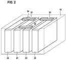
- FIG. 2 is a diagram illustrating a configuration of a battery module 20 according to a preferred embodiment of the present invention.
- the battery module 20 uses the same configuration as that of the battery module 10 according to prior art, as shown in Figure 2 , except that the battery module 20 contains only one temperature sensor 34 instead of multiple temperature sensors.
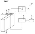
- FIG. 3 is a diagram illustrating a portion of a configuration of a battery module 20 according to a preferred embodiment of the present invention.
- the battery module 20 contains a memory device 50, a sensor unit 60 and a control unit 70.
- the sensor unit 60 is connected to the battery cells 22, 24 in such a way, that it is capable of measuring a current I which flows into or out of the respective battery cell 22, 24.
- the memory device 50 can for example store a maximum allowable temperature gradient, a model reflecting a variation of shape of the cells and/or a housing depending on thermal stress and/or a temperature gradient. Alternatively or additionally, corresponding information on the materials of the battery cell and/or the battery module are stored.
- a predefined admissible deformation can be stored in order to ensure that the corresponding admissible thermal stress is not exceeded. It goes without saying that the admissible thermal stress may alternatively be stored in the data storage without a definition of the predefined admissible deformation.
- Figure 4 is a flow diagram illustrating a method for controlling a temperature and/or a temperature gradient in a battery cell according to a preferred embodiment of the present invention.
- an initial temperature To for each the of the battery cells 22, 24 contained in the battery module 20 is determined.
- the initial temperature To may be obtained at a point in time when the temperature or temperature gradient of each of the battery cells 22, 24 may be the same temperature or temperature gradient, respectively, and may be or correspond to the temperature measured by the one temperature sensor 34.
- the point in time for measuring the initial temperature may be for example an idle state of a system in which the battery module is used. This idle state may be defined for example by a pre-defined minimum period of time that needs to have passed without the system entering another operational state.
- the battery module may contain several temperature sensors, one temperature sensor may be sufficient for the method according to the present invention and may accordingly save cost.
- step 320 of Figure 4 an actual current I which is flowing into or out of the battery cell 22, 24 is measured by means of the sensor unit 60.
- an actual temperature T of the battery cell 22, 24 is determined using a thermal battery cell model described by a differential equation, for which input values comprise at least the determined initial temperature To and the actual measured current I.
- Other input values to the differential equation may comprise battery cell parameters, which are fixed values such as surface areas Ai for the different sides of the battery cell 22, 24 and/or heat transfer coefficients ⁇ i for the surfaces of the different sides of the battery cell 22, 24 and/or a mass m and/or a specific heat capacity cp of the battery cell 22, 24.
- Such fixed input values to the differential equation may be stored in the memory device 50 of the battery module 20.
- Further input values to the differential equation may be variable values such as an actual battery module temperature Tb measured by the temperature sensor 34 inside the battery module 20 and/or an actual ambient temperature Ta in an environment around the battery module 20 measured by an external temperature sensor (not shown).
- an actual temperature of the coolant may be used as a further variable input to the differential equation of the thermal battery cell model.
- the differential equation may look like Equation 1 above.
- the temperatures Ti of all battery cell sides depend on the structure of the battery cell and may be equal to one or more of the air temperature around the battery cell, the temperature of the adjacent battery cell or in case a coolant is used inside the battery module the temperature of the coolant.
- the thermal dissipation loss may be determined by the correlation to Ri*I 2 for the battery cell, wherein Ri denotes an internal resistance value for the battery cell.
- the determined actual temperature T of the battery cell 22, 24 is compared with a pre-defined desired temperature Ts.
- the pre-defined desired temperature Ts may be for example a maximum temperature at which the battery cell 22, 24 is supposed to be operated but which is not to be exceeded. In other cases the pre-defined desired temperature Ts may be a minimum temperature which is to be reached within a certain time period, for example to get to a high performance output of the battery cell 22, 24 quickly.
- the method may proceed by going back to measuring the actual current in step 320.
- Fig. 5 shows a flow diagram in which a temperature gradient reference value is compared to a temperature gradient determined e.g. by means of the above differential equation and/or by measurement by a temperature sensor.
- a temperature estimator T-estimator 71 comprises a control loop ("feedback loop") and operates as a Qdot-limiter.
- Qdot represents the change in heat comprised in the present battery cell.
- the T-estimator 71 receives information about Qdot, Tmod, TEnv and Tcool.
- Qdot represents the heating loss of the battery
- Tmod represents the estimated cell temperature
- TEnv represents the environment temperature
- Tcool represents the coolant temperature of the terminal management.
- the TEnv and Tcool are measured temperatures with sensors, wherein Qdot and Tmod are calculated/modeled values.
- Rhfz represents Ri (Rhfz can be replaced by Ri).
- the T-estimator 71 itself comprises information about the regarded battery cell and / or the battery module e.g. by means of a thermal battery cell model described by a differential equation. In other words, the T-estimator 71 is adapted for calculating based on the received information a maximum change in heat LimQdot and pass same to a maximum current ILim calculator 72 as well as a current battery cell temperature T and pass same to a temperature gradient control block 73.
- Maximum current ILim calculator 72 further receives a reference value Rhfz representing the resistance Ri.
- temperature gradient control block 73 receives an estimated cell temperature T of T-estimator 71. Temperature gradient control block 73 is capable of calculating a current temperature gradient T-gradient and comparing same to a temperature gradient reference value T-gradient reference value.
- temperature gradient control block 73 provides a differential value for the temperature change over time.
- the maximum allowable temperature gradient ⁇ T / ⁇ t can be estimated for example from the calculated cell temperature T and the maximum allowable temperature Tmax.
- a pre-defined desired temperature for a battery cell 22, 24 to be operated at may depend on a specific charge-/discharge mode in which the battery cell 22, 24 is used. Therefore the memory device 50 may be configured to store data sets of operating modes (i.e. charge-/discharge modes) and corresponding pre-defined desired battery cell temperatures. For such cases the method according to the present invention may also comprise a step (not shown) of determining an actual operating mode of the battery cell 22, 24 and automatically determine an associated pre-defined desired battery cell temperature, for example by means of reading from the memory device 50.
- the battery cell may be supposed to operate following a sequence of different charging-/discharging modes. Therefore the memory device 50 may be configured to store data sets of charging-/discharging modes and their corresponding pre-defined desired battery cell temperatures and their corresponding durations (means for how long a battery cell should be operated in a respective charging-/discharging mode) for sequences of different charging-/discharging modes.
Landscapes
- Engineering & Computer Science (AREA)
- Chemical Kinetics & Catalysis (AREA)
- General Chemical & Material Sciences (AREA)
- Electrochemistry (AREA)
- Chemical & Material Sciences (AREA)
- Manufacturing & Machinery (AREA)
- Automation & Control Theory (AREA)
- Algebra (AREA)
- Pure & Applied Mathematics (AREA)
- Mathematical Optimization (AREA)
- Physics & Mathematics (AREA)
- Mathematical Analysis (AREA)
- General Physics & Mathematics (AREA)
- Secondary Cells (AREA)
- Electric Propulsion And Braking For Vehicles (AREA)
Abstract
Description
- The present invention relates to a method and a device for controlling a temperature of a battery cell, and in particular to a method and a device for controlling a temperature in a battery cell which is part of a battery module which may be used in a vehicle.
- It is common in batteries of prior art that a temperature is measured module by module, that is for individual modules of the battery. This is done assuming that temperatures of individual battery cells, of which the battery module is constituted, only differ insignificantly from the temperature determined for the battery module. Accordingly, multiple temperature sensors in battery modules of the prior art are mounted for example on battery cell connectors which connect the battery cells in a battery module.
- Controlling of operating parameters of the battery cells, for example controlling an overall battery output power, to not exceed a pre-defined maximum battery temperature is not part of batteries according to prior art implementations. Since temperature gradients have not been regarded by prior art devices, thermal stress occurring due to irregular distribution of thermal gradients in a battery pack were not possible to be successfully prevented.
- A method for controlling a temperature of a battery cell in a battery module is disclosed, wherein the method comprises the steps of: determining an initial temperature of the battery cell; measuring a current flowing into or out of the battery cell; determining an actual temperature gradient of the battery cell using a thermal battery cell model; comparing the determined temperature gradient of the battery cell with a pre-defined temperature gradient; and automatically adjusting the current flowing into or out of the battery cell according to a result of the comparison.
- In an aspect of the present invention the thermal battery cell model is described by a differential equation. Input values to the differential equation preferably comprise at least the determined initial temperature and the measured current flowing into or out of the battery cell during operation. Additionally constant input values like geometrical parameters of the battery cell and/or thermal parameters of the battery cell and variable input values like temperature values of surroundings of the battery cell and the like may be used with the thermal battery cell model in preferred embodiments.
- In an aspect of the present invention a single temperature sensor may be used to determine an initial temperature as well as to provide an actual temperature, based on which an actual temperature gradient of the battery module during operation can be estimated.
- Further disclosed is a temperature controlling device of a battery cell in a battery module, wherein the device comprises a memory device, a sensor unit and a control unit. The memory device is used for storing a pre-defined thermal battery cell model which is described by a differential equation. Also stored in the memory device are constant parameters of the battery cell to be used together with the thermal battery cell model. The sensor unit is used to determine variable parameters of the battery cell and its environment to be used together with the thermal battery cell model. The parameters to be determined comprise at least a current flowing into or out of the battery cell and a temperature inside the battery module. The control unit is used to perform operations using the parameters read from the memory device and/or determined by the sensor unit and automatically adjust operating parameters of the battery cell based on those operations. The operating parameters of the battery cell to be adjusted comprise at least a current flowing into or out of the battery cell. The control unit is preferably configured to determine an actual temperature gradient of the battery cell using the stored thermal battery cell model, to compare the determined temperature gradient with a pre-defined desired temperature gradient stored in the memory device, and to automatically adjust a current flowing into or out of the battery cell based on the result of the comparison.
- The constant input values to the thermal battery cell model to be stored in the memory device may comprise, for example, area values of battery cell side surfaces, heat transfer coefficients for the different side surfaces of the battery cell, a mass and a specific heat capacity of the battery cell and the like.
- The dependent claims refer to preferred embodiments of the present invention.
- The thermal battery cell model further comprises mechanical information from which a thermal stress resistance of the battery cell and/or the battery module in connection with an actual temperature gradient can be derived. For example the model may reflect a variation of shape of the cells and/or a housing depending on thermal stress and/or a temperature gradient. If corresponding information on the materials of the battery cell and/or the battery module are available (e.g. from a data storage), a predefined admissible deformation can be used in order to ensure that the corresponding admissible thermal stress is not exceeded. It goes without saying that the admissible thermal stress may alternatively be represented in the data storage without a definition of the predefined admissible deformation. Thus, the temperature gradient of the battery cell and/or the battery module can be controlled by adapting e.g. the current through the battery cell or the battery module, respectively. Thus inhomogeneous charging of battery cells due to large temperature gradients can be prevented. The present invention further facilitates preventing inhomogeneous heat in battery cells which are connected in parallel to each other due to different temperature gradients.
- In a preferred embodiment of the present invention the initial temperature is determined by means of a temperature sensor in the battery module at a pre-defined point in time and/or under a predefined condition. To determine the initial temperature of the battery cell, for example, a specific condition or point in time may be used for which it is sufficiently accurate to assume that the temperatures of all battery cells in a battery module are the same. Therefore it may be sufficient to just use one single temperature sensor disposed at a suitable location inside the battery module (e.g. on a battery cell connector) to determine the temperature inside the battery module and assign this temperature as the initial temperature to each individual battery cell.
- According to another aspect of the present invention the method further comprises determining, for example from a measured current, whether the battery cell is in an idle state. The battery cell may be defined to be in an idle state, for example, if no current has flown into or out of the battery cell for a certain predefined amount of time. In this case, measuring the amount of time for which the battery cell remains in the idle state may be part of the method according to a preferred embodiment. The method may further comprise determining, after a pre-defined amount of time has passed with the battery cell remaining in the idle state that the battery cell has reached the point in time and/or the pre-defined condition to allow measuring the initial temperature to be used for each of the battery cells.
- In another preferred embodiment the method further comprises determining, that the actual temperature gradient for each of the battery cells is within a predefined range, in particular equal to the predefined desired temperature gradient. The predefined range (or window) for a temperature gradient may be chosen depending on specific operational modes the battery cell is used in (e.g. a driving state of a vehicle drive train powered by said battery module).
- In yet another preferred embodiment in addition to measuring the temperature inside the battery module by means of an internal temperature sensor the method may further comprise measuring by means of an external temperature sensor an ambient temperature around the battery module to be used as another variable input value for the thermal battery cell model.
- The method according to the present invention preferably further comprises determining an operational mode of the battery cell, for example a charging or discharging mode, and determining the predefined desired temperature gradient during the determined mode of operation. The parameters to be used with the thermal model which correspond to the respective determined mode of operation may be stored as respective sets of data in the memory device of the temperature controlling device according to a preferred embodiment.
- It is further preferred that the method according to the present invention, further comprises: storing of data sets for sequences of charging-/discharging modes and/or corresponding pre-defined desired temperature gradients and/or corresponding pre-defined desired durations, for which a certain stored temperature value is to be maintained in the corresponding charging-/discharging mode. Such a sequence of charging-/discharging modes could be for example an initial idle state, followed by a quick-start state, in which it is allowed to draw a high amount of current from the battery cell for a certain amount of time and/or until a certain maximum temperature or temperature gradient of the battery cell is reached, followed by a relaxed operational state, during which the battery cell temperature is supposed to be brought down to a new lower maximum temperature value, thus less current is allowed to be drawn from the battery cell.
- It is further preferred that the method according to the present invention, further comprises: determining a stored sequence of charging-/discharging modes and corresponding sets of pre-defined desired temperatures or temperature gradients and pre-defined desired durations, for example as described above; determining whether an actual temperature gradient of the battery cell keeps a pre-defined desired temperature gradient for a first charging-/discharging mode of the determined sequence of charging-/discharging modes for an actual time period longer than the corresponding pre-defined duration; and automatically moving to the next charging-/discharging mode of the determined sequence of charging-/discharging modes, if the actual time period is longer than the pre-defined duration.
- A current flowing in the battery module during operation may heat up elements other than the battery cells (e.g. metal plates connecting the battery cells) and therefore may lead to a difference between the measured battery module temperature and the actual battery cell temperature. It is therefore preferred to treat the measured battery module temperature with a weight function depending on an actual current flowing in the battery module before passing it as input value to the thermal battery cell model differential equation. If the current temperature T reaches the predefined temperature Ts, corresponding to a maximum temperature which is allowable for the battery cells / battery module, the maximum current allowed for charging or discharging the battery cell / module can be calculated according to the following equation:

- In order to estimate the maximum current Imax dT = Ts - T and dt = Δt results in:


- Following is a detailed description of preferred embodiments of the present invention with reference to the accompanying drawings. In the drawings
- Figure 1
- is a diagram illustrating an exemplary configuration of a battery module according to prior art,
- Figure 2
- is a diagram illustrating a configuration of a battery module according to a preferred embodiment of the present invention,
- Figure 3
- is a diagram illustrating a portion of a configuration of a battery module according to a preferred embodiment of the present invention,
- Figure 4
- is a flow diagram illustrating the method for controlling a temperature gradient in a battery cell according to a one embodiment of the present invention, and
- Figure 5
- is a flow diagram illustrating the method for controlling a temperature gradient in a battery cell according to a preferred embodiment of the present invention.
-
Figure 1 is a diagram illustrating an exemplary configuration of abattery module 10 according to prior art. A plurality ofbattery cells battery module 10, wherein thebattery cells 22 are located close to the side walls of thebattery module 10, whereas thebattery cells 24 are located towards the center of thebattery module 10. Thebattery cells battery cell connectors 32 made of a conductive material. A plurality oftemperature sensors 34 is mounted on thebattery cell connectors 32, such that a temperature of the respectivebattery cell connectors 32 may be measured. Thetemperature sensors 34 are each connected to an evaluation unit (not shown), which is configured to determine a temperature of thebattery module 10 considering the temperature values of each of thetemperature sensors 34. - In conventional implementations of battery modules it is assumed that temperatures of the individual battery cells only differ little from each other and that temperatures of the individual battery cells are all close to a determined temperature of the entire battery module. However, this assumption is not considering the fact that
battery cells battery module 10 may be exchanging heat with their respective different environment at different rates. For example, abattery cell 22, which is located close to an outer side wall of thebattery module 10, may be able to dissipate heat more efficiently to a cooling environment around thebattery module 10 compared to abattery cell 24, which is located toward the center of thebattery module 10. - In addition, mounting the
temperature sensors 34 on top of thebattery cell connectors 32 may lead to temperature values which are different from the actual temperatures of thebattery cells battery cell connectors 32 may result in varying self-heating of the battery cell connectors. - Also for example aging effects which may have progressed to different levels for each individual battery cell may have an impact on temperature characteristics of the different battery cells therefore contributing to differences in battery cell temperatures or temperature gradients during operation of the battery module.
- In contrast to state of the art battery modules the method and the device for controlling a temperature or a temperature gradient of a battery cell according to embodiments of the present invention determines the temperature for each individual battery cell depending on its individual parameters.
-
Figure 2 is a diagram illustrating a configuration of abattery module 20 according to a preferred embodiment of the present invention. Thebattery module 20 uses the same configuration as that of thebattery module 10 according to prior art, as shown inFigure 2 , except that thebattery module 20 contains only onetemperature sensor 34 instead of multiple temperature sensors. -
Figure 3 is a diagram illustrating a portion of a configuration of abattery module 20 according to a preferred embodiment of the present invention. In addition to the components mentioned above thebattery module 20 according to a preferred embodiment contains amemory device 50, asensor unit 60 and acontrol unit 70. Thesensor unit 60 is connected to thebattery cells respective battery cell memory device 50 can for example store a maximum allowable temperature gradient, a model reflecting a variation of shape of the cells and/or a housing depending on thermal stress and/or a temperature gradient. Alternatively or additionally, corresponding information on the materials of the battery cell and/or the battery module are stored. Alternatively or additionally, a predefined admissible deformation can be stored in order to ensure that the corresponding admissible thermal stress is not exceeded. It goes without saying that the admissible thermal stress may alternatively be stored in the data storage without a definition of the predefined admissible deformation. -
Figure 4 is a flow diagram illustrating a method for controlling a temperature and/or a temperature gradient in a battery cell according to a preferred embodiment of the present invention. - In
step 310 ofFigure 4 an initial temperature To for each the of thebattery cells battery module 20 is determined. In a preferred embodiment the initial temperature To may be obtained at a point in time when the temperature or temperature gradient of each of thebattery cells temperature sensor 34. The point in time for measuring the initial temperature may be for example an idle state of a system in which the battery module is used. This idle state may be defined for example by a pre-defined minimum period of time that needs to have passed without the system entering another operational state. Although the battery module may contain several temperature sensors, one temperature sensor may be sufficient for the method according to the present invention and may accordingly save cost. - In
step 320 ofFigure 4 an actual current I which is flowing into or out of thebattery cell sensor unit 60. - In
step 330 ofFigure 4 an actual temperature T of thebattery cell battery cell battery cell battery cell memory device 50 of thebattery module 20. - Further input values to the differential equation may be variable values such as an actual battery module temperature Tb measured by the
temperature sensor 34 inside thebattery module 20 and/or an actual ambient temperature Ta in an environment around thebattery module 20 measured by an external temperature sensor (not shown). In embodiments which use a coolant inside the battery module around the battery cells, an actual temperature of the coolant may be used as a further variable input to the differential equation of the thermal battery cell model. - The differential equation may look like Equation 1 above.
- The temperatures Ti of all battery cell sides depend on the structure of the battery cell and may be equal to one or more of the air temperature around the battery cell, the temperature of the adjacent battery cell or in case a coolant is used inside the battery module the temperature of the coolant. The thermal dissipation loss may be determined by the correlation to Ri*I2 for the battery cell, wherein Ri denotes an internal resistance value for the battery cell.
- In
step 340 the determined actual temperature T of thebattery cell battery cell battery cell - In
step 350 the current I flowing into or out of thebattery cell step 340. For example, if the determined temperature T of the battery cell is higher than a pre-defined desired temperature Ts, which may represent a maximum temperature limit, the current I may be reduced, such that the actual battery cell temperature T decreases and reaches the pre-defined desired temperature Ts after some time. If the actual temperature T of the battery cell is lower than the pre-defined desired temperature Ts, which may for example represent a desired operating temperature, the current I may be increased until the actual battery cell temperature T increases to the value of the pre-defined desired temperature Ts, thus getting a higher power value from the battery cell. For these cases the target current I may be calculated by re-arranging Equation 1 described above (using Qdot = Ri*I2). - After automatically adjusting the current I flowing into or out of the battery cell in
step 350 the method may proceed by going back to measuring the actual current instep 320. - As it is usually rather difficult to meet an exact temperature value for a
battery cell -
Fig. 5 shows a flow diagram in which a temperature gradient reference value is compared to a temperature gradient determined e.g. by means of the above differential equation and/or by measurement by a temperature sensor. - Three
functional blocks reference sign 70 inFig. 3 ) are shown in order to elucidate the operations in connection with the temperature gradient estimation in connection with a thermal battery cell model according to the present invention. A temperature estimator T-estimator 71 comprises a control loop ("feedback loop") and operates as a Qdot-limiter. Qdot represents the change in heat comprised in the present battery cell. The T-estimator 71 receives information about Qdot, Tmod, TEnv and Tcool. Therein, Qdot represents the heating loss of the battery, Tmod represents the estimated cell temperature, TEnv represents the environment temperature and Tcool represents the coolant temperature of the terminal management. The TEnv and Tcool are measured temperatures with sensors, wherein Qdot and Tmod are calculated/modeled values. Rhfz represents Ri (Rhfz can be replaced by Ri). The T-estimator 71 itself comprises information about the regarded battery cell and / or the battery module e.g. by means of a thermal battery cell model described by a differential equation. In other words, the T-estimator 71 is adapted for calculating based on the received information a maximum change in heat LimQdot and pass same to a maximumcurrent ILim calculator 72 as well as a current battery cell temperature T and pass same to a temperaturegradient control block 73. Maximumcurrent ILim calculator 72 further receives a reference value Rhfz representing the resistance Ri. Based on this information the maximumcurrent ILim calculator 72 calculates a maximum current allowed for the battery cell or battery module in order to limit the change in heat based on the following equation:
current ILim calculator 72 outputs a value ILim, by which signal the charge / discharge of the battery cell / battery module can be controlled in order not to exceed the maximum temperature and/or a maximum temperature change / temperature gradient. On the other hand, temperaturegradient control block 73 receives an estimated cell temperature T of T-estimator 71. Temperaturegradient control block 73 is capable of calculating a current temperature gradient T-gradient and comparing same to a temperature gradient reference value T-gradient reference value. A difference of both values is fed to an amplifier denoted gain, an output of which is fed back to T-estimator 71 (data input ΔT / At). Accordingly, temperaturegradient control block 73 provides a differential value for the temperature change over time. Based on the temperature gradient ΔT / Δt the maximum possible electrical heat generation LimQdot can be estimated by means of the differential equation

- In some embodiments of the present invention a pre-defined desired temperature for a
battery cell battery cell memory device 50 may be configured to store data sets of operating modes (i.e. charge-/discharge modes) and corresponding pre-defined desired battery cell temperatures. For such cases the method according to the present invention may also comprise a step (not shown) of determining an actual operating mode of thebattery cell memory device 50. - In some embodiments of the present invention the battery cell may be supposed to operate following a sequence of different charging-/discharging modes. Therefore the
memory device 50 may be configured to store data sets of charging-/discharging modes and their corresponding pre-defined desired battery cell temperatures and their corresponding durations (means for how long a battery cell should be operated in a respective charging-/discharging mode) for sequences of different charging-/discharging modes. - In addition to the detailed description of the disclosed invention described above it should be noted that for further disclosure of the present invention the accompanying drawings in
Figure 1 to Figure 4 are to be taken into consideration.
Claims (12)
- Method for controlling a temperature of a battery cell (22, 24) in a battery module (20), the method comprising the steps of:- determining an initial temperature of the battery cell (22, 24);- measuring a current (I) flowing into or out of the battery cell (22, 24);- determining an actual temperature gradient of the battery cell (22, 24) using a thermal battery cell model described by a differential equation, for which input values comprise at least the determined initial temperature and the measured current (I);- comparing the determined temperature gradient of the battery cell (22, 24) with a pre-defined desired temperature gradient; and- automatically adjusting the current (I) flowing into or out of the battery cell (22, 24) according to a result of the comparison.
- Method according to claim 1, wherein the thermal battery cell model further comprises mechanical information from which a thermal stress resistance of the battery cell (22, 24) and/or the battery module (20) in connection with an actual temperature gradient can be derived.
- Method according to claim 1 or 2, wherein the initial temperature is determined by means of a temperature sensor (34) in the battery module (20)- at a pre-defined point in time and/or- under a predefined condition.
- Method according to any of the preceding claims, further comprising:- determining from the measured current (I), whether the battery cell is in an idle state;- measuring the amount of time for which the battery cell remains in the idle state;- determining, after a pre-defined amount of time has passed with the battery cell remaining in the idle state, that the battery cell has reached the point in time and/or the pre-defined condition to allow measuring the initial temperature for each of the battery cells.
- Method according to any of the preceding claims, further comprising:- determining, that the actual temperature gradient for each of the battery cells (22, 24) is within a predefined range, in particular equal to the pre-defined desired temperature gradient.
- Method according to any of the preceding claims, wherein the thermal battery cell model comprises- surface areas for the different sides of the battery cell (22, 24) and/or- heat transfer coefficients for the surfaces of the different sides of the battery cell (22, 24) and/or- a mass and a specific heat capacity of the battery cell (22, 24) as fixed input values for the differential equation of the thermal battery cell model.
- Method according to any of the preceding claims, further comprising:- measuring by means of a temperature sensor (34) in the battery module (10) a battery module temperature and/or,- measuring by means of an external temperature sensor (46) an ambient temperature around the battery module (20)as variable input values for the differential equation of the thermal battery cell model.
- Method according to any of the preceding claims further comprising:- determining a charging-/discharging mode of the battery cell (22, 24) and- determining the pre-defined desired temperature gradient during the determined charging-/discharging mode.
- Method according to any of the preceding claims, further comprising:- storing of data sets for sequences of charging-/discharging modes and/or corresponding pre-defined desired temperatures and/or corresponding pre-defined desired durations, for which a certain stored temperature value is to be maintained in the corresponding charging-/discharging mode.
- Method according to any of the preceding claims further comprising:- determining a stored sequence of charging-/discharging modes and corresponding sets of pre-defined desired temperatures and pre-defined desired durations;- determining whether an actual temperature gradient of the battery cell (22, 24) keeps a pre-defined desired temperature gradient for a first charging-/discharging mode of the determined sequence of charging-/discharging modes for an actual time period longer than the corresponding pre-defined duration; and- automatically proceeding to the next charging-/discharging mode of the determined sequence of charging-/discharging modes, if the actual time period is longer than the pre-defined duration.
- Method according to any of the preceding claims further comprising:- adjusting the measured battery module temperature to be used with the thermal battery cell model by a weight factor depending on the measured current (I) flowing into or out of the battery cell.
- A temperature controlling device of a battery cell (22, 24) in a battery module (20), wherein the device comprises:a memory device (50) for storing a pre-defined thermal battery cell model defined by a differential equation, and fix input values of the battery cell (22, 24) for the thermal battery cell model;a sensor unit (60) for determining variable input values for the thermal battery cell model; anda control unit (70), whereinthe sensor unit (60) is configured to at least measure a current (I) flowing into or out of the battery cell (22, 24)the control unit (70) is configured- to determine an actual temperature gradient of the battery cell using the stored thermal battery cell model,- to compare the determined temperature gradient with a pre-defined desired temperature gradient, and- to automatically adjust a current (I) flowing into or out of the battery cell (22, 24) based on this comparison result.
Priority Applications (2)
| Application Number | Priority Date | Filing Date | Title |
|---|---|---|---|
| US15/616,485 US10566805B2 (en) | 2016-06-08 | 2017-06-07 | Method for controlling a temperature of a battery cell |
| CN201710421994.8A CN107959092B (en) | 2016-06-08 | 2017-06-07 | Method for controlling temperature of battery cell |
Applications Claiming Priority (1)
| Application Number | Priority Date | Filing Date | Title |
|---|---|---|---|
| EP16173504 | 2016-06-08 |
Publications (2)
| Publication Number | Publication Date |
|---|---|
| EP3255721A1 true EP3255721A1 (en) | 2017-12-13 |
| EP3255721B1 EP3255721B1 (en) | 2020-04-29 |
Family
ID=56116315
Family Applications (1)
| Application Number | Title | Priority Date | Filing Date |
|---|---|---|---|
| EP17174167.1A Active EP3255721B1 (en) | 2016-06-08 | 2017-06-02 | Method for controlling a temperature of a battery cell |
Country Status (3)
| Country | Link |
|---|---|
| US (1) | US10566805B2 (en) |
| EP (1) | EP3255721B1 (en) |
| CN (1) | CN107959092B (en) |
Cited By (2)
| Publication number | Priority date | Publication date | Assignee | Title |
|---|---|---|---|---|
| CN110364785A (en) * | 2019-06-12 | 2019-10-22 | 爱驰汽车有限公司 | Temperature control device for electric vehicle and electric vehicle |
| GB2595496A (en) * | 2020-05-28 | 2021-12-01 | Jaguar Land Rover Ltd | System and method for determination of battery temperature |
Families Citing this family (18)
| Publication number | Priority date | Publication date | Assignee | Title |
|---|---|---|---|---|
| DE102017209182A1 (en) * | 2017-05-31 | 2018-12-06 | Bayerische Motoren Werke Aktiengesellschaft | Method and device for determining an operating temperature, operating method for a battery cell, control unit for a battery cell and working device |
| DE102018214984A1 (en) * | 2018-09-04 | 2020-03-05 | Robert Bosch Gmbh | Method for determining an ambient temperature of a first electrical energy storage unit in conjunction with second electrical energy storage units, and corresponding device, computer program and machine-readable storage medium |
| CN111130154B (en) * | 2018-10-30 | 2024-06-07 | 中兴通讯股份有限公司 | Charging and discharging control method and device of terminal, storage medium and electronic device |
| KR102465889B1 (en) * | 2018-12-18 | 2022-11-09 | 주식회사 엘지에너지솔루션 | Apparatus and Method for Controlling Charging of Secondary Battery Pack |
| EP3826102A1 (en) * | 2019-11-20 | 2021-05-26 | Vestas Wind Systems A/S | Model based monitoring of battery system |
| DE102019219629A1 (en) * | 2019-12-13 | 2021-06-17 | Robert Bosch Gmbh | Method for diagnosing a temperature control device of a battery pack |
| CN112310512B (en) * | 2020-11-04 | 2021-08-17 | 烟台创为新能源科技股份有限公司 | Method and system for intelligently adjusting temperature of battery |
| CN113022378B (en) * | 2021-03-01 | 2023-03-07 | 中国第一汽车股份有限公司 | Temperature consistency prediction method, temperature consistency prediction device, prediction equipment and storage medium |
| CN112910048A (en) * | 2021-03-05 | 2021-06-04 | 东方醒狮(福建)储能科技有限公司 | Control method of new energy storage and charging platform based on thermal management technology |
| CN112803553A (en) * | 2021-03-05 | 2021-05-14 | 东方醒狮(福建)储能科技有限公司 | New energy storage and charging platform based on heat management technology |
| KR102663022B1 (en) * | 2021-03-26 | 2024-05-07 | 삼성에스디아이 주식회사 | Battery system and Method of controlling the same |
| DE102021205402A1 (en) * | 2021-05-27 | 2022-12-01 | Robert Bosch Gesellschaft mit beschränkter Haftung | Method for monitoring a temperature of a battery |
| CN114243860B (en) * | 2021-12-28 | 2025-05-23 | 北京小米移动软件有限公司 | Method and device for determining battery temperature, storage medium and electronic equipment |
| US12542450B2 (en) * | 2022-08-24 | 2026-02-03 | GM Global Technology Operations LLC | Method and system for charging a battery |
| CN116231172B (en) * | 2022-12-27 | 2024-01-16 | 重庆三峡时代能源科技有限公司 | Battery heat management method, device, equipment and storage medium |
| CN116215319B (en) * | 2023-02-06 | 2025-05-02 | 岚图汽车科技有限公司 | Power battery system temperature anomaly monitoring method, system and storage medium |
| DE102023116561A1 (en) * | 2023-06-23 | 2024-12-24 | Technische Universität Graz | Method for determining a temperature behavior of a battery, a control device, a computer program product and a vehicle or a stationary storage device with a control device |
| CN119567875A (en) * | 2024-12-20 | 2025-03-07 | 北京新能源汽车股份有限公司 | Battery charging time prediction method, device, prediction equipment, product and medium |
Citations (5)
| Publication number | Priority date | Publication date | Assignee | Title |
|---|---|---|---|---|
| US6204639B1 (en) * | 1999-02-26 | 2001-03-20 | Hitachi Koki Co., Ltd. | Battery charger determining charging conditions depending upon whether a cooling device is provided |
| US6271643B1 (en) * | 1986-12-18 | 2001-08-07 | Intermec Ip Corp. | Battery pack having memory |
| DE102013000220B3 (en) * | 2013-01-04 | 2014-04-03 | Volkswagen Aktiengesellschaft | Method for determining temperature in electrical element e.g. accumulator, involves determining electric terminal power, power dissipation, heat capacity, thermal conductivity and heat transfer resistance to electrical element |
| US20140095092A1 (en) * | 2012-09-28 | 2014-04-03 | Fujitsu Limited | State evaluation apparatus of secondary battery, state evaluation method of secondary battery, and computer-readable medium storing state evaluation program of secondary battery |
| US20140377605A1 (en) * | 2011-09-15 | 2014-12-25 | Renault S.A.S. | Method for estimating the temperature at the core of a battery cell |
Family Cites Families (13)
| Publication number | Priority date | Publication date | Assignee | Title |
|---|---|---|---|---|
| US6076964A (en) * | 1998-11-11 | 2000-06-20 | Chrysler Corporation | Prediction of internal temperature of a battery using a non-linear dynamic model |
| JP3777981B2 (en) * | 2000-04-13 | 2006-05-24 | トヨタ自動車株式会社 | Vehicle power supply |
| JP3936286B2 (en) * | 2002-12-24 | 2007-06-27 | 株式会社マキタ | Charging apparatus and charging method |
| US20100047682A1 (en) * | 2007-03-01 | 2010-02-25 | Johnson Controls - SAFT Advanced Power Solutions, LLC | Battery system and thermal management system therefor |
| JP5219485B2 (en) * | 2007-12-12 | 2013-06-26 | 三洋電機株式会社 | Charging method |
| CN102473981B (en) * | 2009-09-30 | 2014-11-12 | 株式会社日立制作所 | Electrical storage module |
| DE102009051613A1 (en) * | 2009-11-02 | 2011-05-05 | Vega Grieshaber Kg | cell |
| DE102010063376A1 (en) * | 2010-12-17 | 2012-06-21 | Bayerische Motoren Werke Aktiengesellschaft | Temperature control method for an electrochemical energy store in a vehicle |
| DE102011075462A1 (en) * | 2011-05-06 | 2012-11-08 | Sb Limotive Company Ltd. | Battery module a battery cell stack of at least two battery cells having a passive air conditioning and motor vehicle |
| JP5461602B2 (en) * | 2012-02-20 | 2014-04-02 | 三菱重工業株式会社 | Power management system |
| DE112014000419T5 (en) * | 2013-01-14 | 2015-10-15 | Gentherm Incorporated | Thermoelectric based thermal management of electrical devices |
| US9531042B2 (en) * | 2013-01-28 | 2016-12-27 | GM Global Technology Operations LLC | Battery target temperature methods and systems |
| DE102013214448A1 (en) * | 2013-07-24 | 2015-01-29 | Robert Bosch Gmbh | Method and device for detecting a temperature increase in a plurality of electrochemical storage cells |
-
2017
- 2017-06-02 EP EP17174167.1A patent/EP3255721B1/en active Active
- 2017-06-07 US US15/616,485 patent/US10566805B2/en active Active
- 2017-06-07 CN CN201710421994.8A patent/CN107959092B/en active Active
Patent Citations (5)
| Publication number | Priority date | Publication date | Assignee | Title |
|---|---|---|---|---|
| US6271643B1 (en) * | 1986-12-18 | 2001-08-07 | Intermec Ip Corp. | Battery pack having memory |
| US6204639B1 (en) * | 1999-02-26 | 2001-03-20 | Hitachi Koki Co., Ltd. | Battery charger determining charging conditions depending upon whether a cooling device is provided |
| US20140377605A1 (en) * | 2011-09-15 | 2014-12-25 | Renault S.A.S. | Method for estimating the temperature at the core of a battery cell |
| US20140095092A1 (en) * | 2012-09-28 | 2014-04-03 | Fujitsu Limited | State evaluation apparatus of secondary battery, state evaluation method of secondary battery, and computer-readable medium storing state evaluation program of secondary battery |
| DE102013000220B3 (en) * | 2013-01-04 | 2014-04-03 | Volkswagen Aktiengesellschaft | Method for determining temperature in electrical element e.g. accumulator, involves determining electric terminal power, power dissipation, heat capacity, thermal conductivity and heat transfer resistance to electrical element |
Non-Patent Citations (1)
| Title |
|---|
| KI-YONG OH ET AL: "A novel thermal swelling model for a rechargeable lithium-ion battery cell", JOURNAL OF POWER SOURCES, vol. 303, 8 November 2015 (2015-11-08), CH, pages 86 - 96, XP055405799, ISSN: 0378-7753, DOI: 10.1016/j.jpowsour.2015.10.085 * |
Cited By (3)
| Publication number | Priority date | Publication date | Assignee | Title |
|---|---|---|---|---|
| CN110364785A (en) * | 2019-06-12 | 2019-10-22 | 爱驰汽车有限公司 | Temperature control device for electric vehicle and electric vehicle |
| GB2595496A (en) * | 2020-05-28 | 2021-12-01 | Jaguar Land Rover Ltd | System and method for determination of battery temperature |
| GB2595496B (en) * | 2020-05-28 | 2024-05-08 | Jaguar Land Rover Ltd | System and method for determination of battery temperature |
Also Published As
| Publication number | Publication date |
|---|---|
| US20170358933A1 (en) | 2017-12-14 |
| CN107959092A (en) | 2018-04-24 |
| CN107959092B (en) | 2022-06-14 |
| EP3255721B1 (en) | 2020-04-29 |
| US10566805B2 (en) | 2020-02-18 |
Similar Documents
| Publication | Publication Date | Title |
|---|---|---|
| US10566805B2 (en) | Method for controlling a temperature of a battery cell | |
| JP5026823B2 (en) | Battery cooling system | |
| KR102916353B1 (en) | Vehicle and controlling method of vehicle | |
| EP3929606B1 (en) | Battery management system, battery pack, electric vehicle, and battery management method | |
| US8004239B2 (en) | Battery management system for calculating charge and disharge powers | |
| US11374425B2 (en) | Battery energy storage system, battery management system, and control method for controlling battery temperature | |
| US10732229B2 (en) | Battery pack | |
| US9827871B2 (en) | Adaptive thermal management of an electric energy storage method and system apparatus | |
| US20140347012A1 (en) | Battery management system and method of driving the same | |
| CN105359329B (en) | Method for battery management and battery management system | |
| EP3828568B1 (en) | Battery management apparatus, battery management method and battery pack | |
| CN103502829A (en) | Optimized method for managing heat in an electrochemical storage system | |
| US20120011706A1 (en) | Battery assembling apparatus and battery assembling method | |
| KR20180079771A (en) | Battery management apparatus and soc calibrating method using the same | |
| EP2792012B1 (en) | System and method for determining charging and discharging power levels for a battery pack | |
| US11660980B2 (en) | Energy conscious warm-up of lithium-ion cells from sub-zero temperatures | |
| US11616257B2 (en) | Battery management device | |
| EP3425721A1 (en) | Thermal management system for batteries | |
| EP3805768B1 (en) | Battery management apparatus, battery management method, and battery pack | |
| CN103259058A (en) | Power management system | |
| CN112255558A (en) | Method and device for calculating battery calendar life attenuation | |
| US20130275065A1 (en) | Method for predicting the power an electrochemical energy store can output to an electrical load | |
| JP2006226788A (en) | Battery management system | |
| JPH11109004A (en) | Residual capacity meter for battery and method for measuring residual capacity of a plurality of batteries | |
| JP2007109536A (en) | Temperature detector |
Legal Events
| Date | Code | Title | Description |
|---|---|---|---|
| PUAI | Public reference made under article 153(3) epc to a published international application that has entered the european phase |
Free format text: ORIGINAL CODE: 0009012 |
|
| STAA | Information on the status of an ep patent application or granted ep patent |
Free format text: STATUS: THE APPLICATION HAS BEEN PUBLISHED |
|
| AK | Designated contracting states |
Kind code of ref document: A1 Designated state(s): AL AT BE BG CH CY CZ DE DK EE ES FI FR GB GR HR HU IE IS IT LI LT LU LV MC MK MT NL NO PL PT RO RS SE SI SK SM TR |
|
| AX | Request for extension of the european patent |
Extension state: BA ME |
|
| STAA | Information on the status of an ep patent application or granted ep patent |
Free format text: STATUS: REQUEST FOR EXAMINATION WAS MADE |
|
| 17P | Request for examination filed |
Effective date: 20180613 |
|
| RBV | Designated contracting states (corrected) |
Designated state(s): AL AT BE BG CH CY CZ DE DK EE ES FI FR GB GR HR HU IE IS IT LI LT LU LV MC MK MT NL NO PL PT RO RS SE SI SK SM TR |
|
| STAA | Information on the status of an ep patent application or granted ep patent |
Free format text: STATUS: EXAMINATION IS IN PROGRESS |
|
| 17Q | First examination report despatched |
Effective date: 20190212 |
|
| RAP1 | Party data changed (applicant data changed or rights of an application transferred) |
Owner name: ROBERT BOSCH GMBH Owner name: GS YUASA INTERNATIONAL LTD. |
|
| REG | Reference to a national code |
Ref country code: DE Ref legal event code: R079 Ref document number: 602017015509 Country of ref document: DE Free format text: PREVIOUS MAIN CLASS: H01M0010480000 Ipc: H01M0010615000 |
|
| GRAP | Despatch of communication of intention to grant a patent |
Free format text: ORIGINAL CODE: EPIDOSNIGR1 |
|
| STAA | Information on the status of an ep patent application or granted ep patent |
Free format text: STATUS: GRANT OF PATENT IS INTENDED |
|
| RIC1 | Information provided on ipc code assigned before grant |
Ipc: H01M 10/44 20060101ALI20191030BHEP Ipc: H01M 10/635 20140101ALI20191030BHEP Ipc: H01M 10/625 20140101ALI20191030BHEP Ipc: H01M 10/615 20140101AFI20191030BHEP Ipc: H01M 10/637 20140101ALI20191030BHEP Ipc: H01M 10/48 20060101ALI20191030BHEP Ipc: H01M 10/652 20140101ALI20191030BHEP Ipc: H01M 10/633 20140101ALI20191030BHEP |
|
| INTG | Intention to grant announced |
Effective date: 20191126 |
|
| GRAS | Grant fee paid |
Free format text: ORIGINAL CODE: EPIDOSNIGR3 |
|
| GRAA | (expected) grant |
Free format text: ORIGINAL CODE: 0009210 |
|
| STAA | Information on the status of an ep patent application or granted ep patent |
Free format text: STATUS: THE PATENT HAS BEEN GRANTED |
|
| AK | Designated contracting states |
Kind code of ref document: B1 Designated state(s): AL AT BE BG CH CY CZ DE DK EE ES FI FR GB GR HR HU IE IS IT LI LT LU LV MC MK MT NL NO PL PT RO RS SE SI SK SM TR |
|
| RAP1 | Party data changed (applicant data changed or rights of an application transferred) |
Owner name: ROBERT BOSCH GMBH Owner name: GS YUASA INTERNATIONAL LTD. |
|
| REG | Reference to a national code |
Ref country code: GB Ref legal event code: FG4D |
|
| REG | Reference to a national code |
Ref country code: CH Ref legal event code: EP |
|
| REG | Reference to a national code |
Ref country code: AT Ref legal event code: REF Ref document number: 1264674 Country of ref document: AT Kind code of ref document: T Effective date: 20200515 |
|
| REG | Reference to a national code |
Ref country code: DE Ref legal event code: R096 Ref document number: 602017015509 Country of ref document: DE |
|
| REG | Reference to a national code |
Ref country code: IE Ref legal event code: FG4D |
|
| REG | Reference to a national code |
Ref country code: NL Ref legal event code: MP Effective date: 20200429 |
|
| REG | Reference to a national code |
Ref country code: LT Ref legal event code: MG4D |
|
| PG25 | Lapsed in a contracting state [announced via postgrant information from national office to epo] |
Ref country code: FI Free format text: LAPSE BECAUSE OF FAILURE TO SUBMIT A TRANSLATION OF THE DESCRIPTION OR TO PAY THE FEE WITHIN THE PRESCRIBED TIME-LIMIT Effective date: 20200429 Ref country code: LT Free format text: LAPSE BECAUSE OF FAILURE TO SUBMIT A TRANSLATION OF THE DESCRIPTION OR TO PAY THE FEE WITHIN THE PRESCRIBED TIME-LIMIT Effective date: 20200429 Ref country code: SE Free format text: LAPSE BECAUSE OF FAILURE TO SUBMIT A TRANSLATION OF THE DESCRIPTION OR TO PAY THE FEE WITHIN THE PRESCRIBED TIME-LIMIT Effective date: 20200429 Ref country code: IS Free format text: LAPSE BECAUSE OF FAILURE TO SUBMIT A TRANSLATION OF THE DESCRIPTION OR TO PAY THE FEE WITHIN THE PRESCRIBED TIME-LIMIT Effective date: 20200829 Ref country code: PT Free format text: LAPSE BECAUSE OF FAILURE TO SUBMIT A TRANSLATION OF THE DESCRIPTION OR TO PAY THE FEE WITHIN THE PRESCRIBED TIME-LIMIT Effective date: 20200831 Ref country code: NO Free format text: LAPSE BECAUSE OF FAILURE TO SUBMIT A TRANSLATION OF THE DESCRIPTION OR TO PAY THE FEE WITHIN THE PRESCRIBED TIME-LIMIT Effective date: 20200729 Ref country code: GR Free format text: LAPSE BECAUSE OF FAILURE TO SUBMIT A TRANSLATION OF THE DESCRIPTION OR TO PAY THE FEE WITHIN THE PRESCRIBED TIME-LIMIT Effective date: 20200730 |
|
| REG | Reference to a national code |
Ref country code: AT Ref legal event code: MK05 Ref document number: 1264674 Country of ref document: AT Kind code of ref document: T Effective date: 20200429 |
|
| PG25 | Lapsed in a contracting state [announced via postgrant information from national office to epo] |
Ref country code: HR Free format text: LAPSE BECAUSE OF FAILURE TO SUBMIT A TRANSLATION OF THE DESCRIPTION OR TO PAY THE FEE WITHIN THE PRESCRIBED TIME-LIMIT Effective date: 20200429 Ref country code: RS Free format text: LAPSE BECAUSE OF FAILURE TO SUBMIT A TRANSLATION OF THE DESCRIPTION OR TO PAY THE FEE WITHIN THE PRESCRIBED TIME-LIMIT Effective date: 20200429 Ref country code: LV Free format text: LAPSE BECAUSE OF FAILURE TO SUBMIT A TRANSLATION OF THE DESCRIPTION OR TO PAY THE FEE WITHIN THE PRESCRIBED TIME-LIMIT Effective date: 20200429 Ref country code: BG Free format text: LAPSE BECAUSE OF FAILURE TO SUBMIT A TRANSLATION OF THE DESCRIPTION OR TO PAY THE FEE WITHIN THE PRESCRIBED TIME-LIMIT Effective date: 20200729 |
|
| PG25 | Lapsed in a contracting state [announced via postgrant information from national office to epo] |
Ref country code: AL Free format text: LAPSE BECAUSE OF FAILURE TO SUBMIT A TRANSLATION OF THE DESCRIPTION OR TO PAY THE FEE WITHIN THE PRESCRIBED TIME-LIMIT Effective date: 20200429 Ref country code: NL Free format text: LAPSE BECAUSE OF FAILURE TO SUBMIT A TRANSLATION OF THE DESCRIPTION OR TO PAY THE FEE WITHIN THE PRESCRIBED TIME-LIMIT Effective date: 20200429 |
|
| PG25 | Lapsed in a contracting state [announced via postgrant information from national office to epo] |
Ref country code: ES Free format text: LAPSE BECAUSE OF FAILURE TO SUBMIT A TRANSLATION OF THE DESCRIPTION OR TO PAY THE FEE WITHIN THE PRESCRIBED TIME-LIMIT Effective date: 20200429 Ref country code: MC Free format text: LAPSE BECAUSE OF FAILURE TO SUBMIT A TRANSLATION OF THE DESCRIPTION OR TO PAY THE FEE WITHIN THE PRESCRIBED TIME-LIMIT Effective date: 20200429 Ref country code: SM Free format text: LAPSE BECAUSE OF FAILURE TO SUBMIT A TRANSLATION OF THE DESCRIPTION OR TO PAY THE FEE WITHIN THE PRESCRIBED TIME-LIMIT Effective date: 20200429 Ref country code: EE Free format text: LAPSE BECAUSE OF FAILURE TO SUBMIT A TRANSLATION OF THE DESCRIPTION OR TO PAY THE FEE WITHIN THE PRESCRIBED TIME-LIMIT Effective date: 20200429 Ref country code: DK Free format text: LAPSE BECAUSE OF FAILURE TO SUBMIT A TRANSLATION OF THE DESCRIPTION OR TO PAY THE FEE WITHIN THE PRESCRIBED TIME-LIMIT Effective date: 20200429 Ref country code: RO Free format text: LAPSE BECAUSE OF FAILURE TO SUBMIT A TRANSLATION OF THE DESCRIPTION OR TO PAY THE FEE WITHIN THE PRESCRIBED TIME-LIMIT Effective date: 20200429 Ref country code: AT Free format text: LAPSE BECAUSE OF FAILURE TO SUBMIT A TRANSLATION OF THE DESCRIPTION OR TO PAY THE FEE WITHIN THE PRESCRIBED TIME-LIMIT Effective date: 20200429 Ref country code: CZ Free format text: LAPSE BECAUSE OF FAILURE TO SUBMIT A TRANSLATION OF THE DESCRIPTION OR TO PAY THE FEE WITHIN THE PRESCRIBED TIME-LIMIT Effective date: 20200429 |
|
| REG | Reference to a national code |
Ref country code: CH Ref legal event code: PL |
|
| REG | Reference to a national code |
Ref country code: DE Ref legal event code: R097 Ref document number: 602017015509 Country of ref document: DE |
|
| PG25 | Lapsed in a contracting state [announced via postgrant information from national office to epo] |
Ref country code: PL Free format text: LAPSE BECAUSE OF FAILURE TO SUBMIT A TRANSLATION OF THE DESCRIPTION OR TO PAY THE FEE WITHIN THE PRESCRIBED TIME-LIMIT Effective date: 20200429 Ref country code: SK Free format text: LAPSE BECAUSE OF FAILURE TO SUBMIT A TRANSLATION OF THE DESCRIPTION OR TO PAY THE FEE WITHIN THE PRESCRIBED TIME-LIMIT Effective date: 20200429 |
|
| PLBE | No opposition filed within time limit |
Free format text: ORIGINAL CODE: 0009261 |
|
| STAA | Information on the status of an ep patent application or granted ep patent |
Free format text: STATUS: NO OPPOSITION FILED WITHIN TIME LIMIT |
|
| PG25 | Lapsed in a contracting state [announced via postgrant information from national office to epo] |
Ref country code: LU Free format text: LAPSE BECAUSE OF NON-PAYMENT OF DUE FEES Effective date: 20200602 |
|
| 26N | No opposition filed |
Effective date: 20210201 |
|
| REG | Reference to a national code |
Ref country code: BE Ref legal event code: MM Effective date: 20200630 |
|
| PG25 | Lapsed in a contracting state [announced via postgrant information from national office to epo] |
Ref country code: CH Free format text: LAPSE BECAUSE OF NON-PAYMENT OF DUE FEES Effective date: 20200630 Ref country code: LI Free format text: LAPSE BECAUSE OF NON-PAYMENT OF DUE FEES Effective date: 20200630 Ref country code: IE Free format text: LAPSE BECAUSE OF NON-PAYMENT OF DUE FEES Effective date: 20200602 |
|
| PG25 | Lapsed in a contracting state [announced via postgrant information from national office to epo] |
Ref country code: BE Free format text: LAPSE BECAUSE OF NON-PAYMENT OF DUE FEES Effective date: 20200630 Ref country code: SI Free format text: LAPSE BECAUSE OF FAILURE TO SUBMIT A TRANSLATION OF THE DESCRIPTION OR TO PAY THE FEE WITHIN THE PRESCRIBED TIME-LIMIT Effective date: 20200429 |
|
| GBPC | Gb: european patent ceased through non-payment of renewal fee |
Effective date: 20210602 |
|
| PG25 | Lapsed in a contracting state [announced via postgrant information from national office to epo] |
Ref country code: GB Free format text: LAPSE BECAUSE OF NON-PAYMENT OF DUE FEES Effective date: 20210602 |
|
| PG25 | Lapsed in a contracting state [announced via postgrant information from national office to epo] |
Ref country code: TR Free format text: LAPSE BECAUSE OF FAILURE TO SUBMIT A TRANSLATION OF THE DESCRIPTION OR TO PAY THE FEE WITHIN THE PRESCRIBED TIME-LIMIT Effective date: 20200429 Ref country code: MT Free format text: LAPSE BECAUSE OF FAILURE TO SUBMIT A TRANSLATION OF THE DESCRIPTION OR TO PAY THE FEE WITHIN THE PRESCRIBED TIME-LIMIT Effective date: 20200429 Ref country code: CY Free format text: LAPSE BECAUSE OF FAILURE TO SUBMIT A TRANSLATION OF THE DESCRIPTION OR TO PAY THE FEE WITHIN THE PRESCRIBED TIME-LIMIT Effective date: 20200429 |
|
| PG25 | Lapsed in a contracting state [announced via postgrant information from national office to epo] |
Ref country code: MK Free format text: LAPSE BECAUSE OF FAILURE TO SUBMIT A TRANSLATION OF THE DESCRIPTION OR TO PAY THE FEE WITHIN THE PRESCRIBED TIME-LIMIT Effective date: 20200429 |
|
| PGFP | Annual fee paid to national office [announced via postgrant information from national office to epo] |
Ref country code: IT Payment date: 20240625 Year of fee payment: 8 |
|
| PGFP | Annual fee paid to national office [announced via postgrant information from national office to epo] |
Ref country code: FR Payment date: 20250625 Year of fee payment: 9 |
|
| PGFP | Annual fee paid to national office [announced via postgrant information from national office to epo] |
Ref country code: DE Payment date: 20250630 Year of fee payment: 9 |
|
| PG25 | Lapsed in a contracting state [announced via postgrant information from national office to epo] |
Ref country code: IT Free format text: LAPSE BECAUSE OF NON-PAYMENT OF DUE FEES Effective date: 20250602 |