EP3255512A2 - Auf adaptivem modell basierendes verfahren zur quantifizierung der verschlechterung eines stromerzeugungssystems - Google Patents
Auf adaptivem modell basierendes verfahren zur quantifizierung der verschlechterung eines stromerzeugungssystems Download PDFInfo
- Publication number
- EP3255512A2 EP3255512A2 EP17173673.9A EP17173673A EP3255512A2 EP 3255512 A2 EP3255512 A2 EP 3255512A2 EP 17173673 A EP17173673 A EP 17173673A EP 3255512 A2 EP3255512 A2 EP 3255512A2
- Authority
- EP
- European Patent Office
- Prior art keywords
- parameter
- model
- power generation
- generation system
- gas turbine
- Prior art date
- Legal status (The legal status is an assumption and is not a legal conclusion. Google has not performed a legal analysis and makes no representation as to the accuracy of the status listed.)
- Granted
Links
- 238000010248 power generation Methods 0.000 title claims abstract description 78
- 230000015556 catabolic process Effects 0.000 title claims abstract description 65
- 238000006731 degradation reaction Methods 0.000 title claims abstract description 65
- 238000000034 method Methods 0.000 title claims description 26
- 230000003044 adaptive effect Effects 0.000 title claims description 7
- 230000006870 function Effects 0.000 claims abstract description 111
- 238000012546 transfer Methods 0.000 claims abstract description 97
- 238000012937 correction Methods 0.000 claims abstract description 48
- 239000011159 matrix material Substances 0.000 claims description 7
- 238000012423 maintenance Methods 0.000 claims description 6
- 238000004088 simulation Methods 0.000 claims description 6
- 230000000875 corresponding effect Effects 0.000 description 16
- 230000000694 effects Effects 0.000 description 8
- 239000000446 fuel Substances 0.000 description 5
- 238000010586 diagram Methods 0.000 description 4
- 238000004519 manufacturing process Methods 0.000 description 4
- 238000005259 measurement Methods 0.000 description 4
- 238000003860 storage Methods 0.000 description 4
- 238000011217 control strategy Methods 0.000 description 3
- 239000012080 ambient air Substances 0.000 description 2
- 230000008901 benefit Effects 0.000 description 2
- 238000002485 combustion reaction Methods 0.000 description 2
- 238000005094 computer simulation Methods 0.000 description 2
- 230000001276 controlling effect Effects 0.000 description 2
- 238000005314 correlation function Methods 0.000 description 2
- 238000013461 design Methods 0.000 description 2
- 238000011161 development Methods 0.000 description 2
- 101710098560 NADPH-cytochrome P450 reductase 2 Proteins 0.000 description 1
- 239000011358 absorbing material Substances 0.000 description 1
- 239000003570 air Substances 0.000 description 1
- 238000013459 approach Methods 0.000 description 1
- 238000009529 body temperature measurement Methods 0.000 description 1
- 238000004140 cleaning Methods 0.000 description 1
- 238000004891 communication Methods 0.000 description 1
- 238000010276 construction Methods 0.000 description 1
- 230000002596 correlated effect Effects 0.000 description 1
- 239000000428 dust Substances 0.000 description 1
- 239000012636 effector Substances 0.000 description 1
- 238000009434 installation Methods 0.000 description 1
- 239000000463 material Substances 0.000 description 1
- 238000007620 mathematical function Methods 0.000 description 1
- 238000012544 monitoring process Methods 0.000 description 1
- 238000010606 normalization Methods 0.000 description 1
- 230000003287 optical effect Effects 0.000 description 1
- 230000003068 static effect Effects 0.000 description 1
- XLYOFNOQVPJJNP-UHFFFAOYSA-N water Substances O XLYOFNOQVPJJNP-UHFFFAOYSA-N 0.000 description 1
Images
Classifications
-
- F—MECHANICAL ENGINEERING; LIGHTING; HEATING; WEAPONS; BLASTING
- F01—MACHINES OR ENGINES IN GENERAL; ENGINE PLANTS IN GENERAL; STEAM ENGINES
- F01D—NON-POSITIVE DISPLACEMENT MACHINES OR ENGINES, e.g. STEAM TURBINES
- F01D21/00—Shutting-down of machines or engines, e.g. in emergency; Regulating, controlling, or safety means not otherwise provided for
- F01D21/003—Arrangements for testing or measuring
-
- G—PHYSICS
- G05—CONTROLLING; REGULATING
- G05B—CONTROL OR REGULATING SYSTEMS IN GENERAL; FUNCTIONAL ELEMENTS OF SUCH SYSTEMS; MONITORING OR TESTING ARRANGEMENTS FOR SUCH SYSTEMS OR ELEMENTS
- G05B17/00—Systems involving the use of models or simulators of said systems
- G05B17/02—Systems involving the use of models or simulators of said systems electric
-
- F—MECHANICAL ENGINEERING; LIGHTING; HEATING; WEAPONS; BLASTING
- F01—MACHINES OR ENGINES IN GENERAL; ENGINE PLANTS IN GENERAL; STEAM ENGINES
- F01D—NON-POSITIVE DISPLACEMENT MACHINES OR ENGINES, e.g. STEAM TURBINES
- F01D25/00—Component parts, details, or accessories, not provided for in, or of interest apart from, other groups
- F01D25/002—Cleaning of turbomachines
-
- G—PHYSICS
- G05—CONTROLLING; REGULATING
- G05B—CONTROL OR REGULATING SYSTEMS IN GENERAL; FUNCTIONAL ELEMENTS OF SUCH SYSTEMS; MONITORING OR TESTING ARRANGEMENTS FOR SUCH SYSTEMS OR ELEMENTS
- G05B13/00—Adaptive control systems, i.e. systems automatically adjusting themselves to have a performance which is optimum according to some preassigned criterion
- G05B13/02—Adaptive control systems, i.e. systems automatically adjusting themselves to have a performance which is optimum according to some preassigned criterion electric
- G05B13/04—Adaptive control systems, i.e. systems automatically adjusting themselves to have a performance which is optimum according to some preassigned criterion electric involving the use of models or simulators
- G05B13/041—Adaptive control systems, i.e. systems automatically adjusting themselves to have a performance which is optimum according to some preassigned criterion electric involving the use of models or simulators in which a variable is automatically adjusted to optimise the performance
-
- G—PHYSICS
- G05—CONTROLLING; REGULATING
- G05B—CONTROL OR REGULATING SYSTEMS IN GENERAL; FUNCTIONAL ELEMENTS OF SUCH SYSTEMS; MONITORING OR TESTING ARRANGEMENTS FOR SUCH SYSTEMS OR ELEMENTS
- G05B23/00—Testing or monitoring of control systems or parts thereof
- G05B23/02—Electric testing or monitoring
- G05B23/0205—Electric testing or monitoring by means of a monitoring system capable of detecting and responding to faults
- G05B23/0218—Electric testing or monitoring by means of a monitoring system capable of detecting and responding to faults characterised by the fault detection method dealing with either existing or incipient faults
- G05B23/0243—Electric testing or monitoring by means of a monitoring system capable of detecting and responding to faults characterised by the fault detection method dealing with either existing or incipient faults model based detection method, e.g. first-principles knowledge model
- G05B23/0254—Electric testing or monitoring by means of a monitoring system capable of detecting and responding to faults characterised by the fault detection method dealing with either existing or incipient faults model based detection method, e.g. first-principles knowledge model based on a quantitative model, e.g. mathematical relationships between inputs and outputs; functions: observer, Kalman filter, residual calculation, Neural Networks
-
- G—PHYSICS
- G05—CONTROLLING; REGULATING
- G05B—CONTROL OR REGULATING SYSTEMS IN GENERAL; FUNCTIONAL ELEMENTS OF SUCH SYSTEMS; MONITORING OR TESTING ARRANGEMENTS FOR SUCH SYSTEMS OR ELEMENTS
- G05B23/00—Testing or monitoring of control systems or parts thereof
- G05B23/02—Electric testing or monitoring
- G05B23/0205—Electric testing or monitoring by means of a monitoring system capable of detecting and responding to faults
- G05B23/0259—Electric testing or monitoring by means of a monitoring system capable of detecting and responding to faults characterized by the response to fault detection
- G05B23/0283—Predictive maintenance, e.g. involving the monitoring of a system and, based on the monitoring results, taking decisions on the maintenance schedule of the monitored system; Estimating remaining useful life [RUL]
-
- F—MECHANICAL ENGINEERING; LIGHTING; HEATING; WEAPONS; BLASTING
- F05—INDEXING SCHEMES RELATING TO ENGINES OR PUMPS IN VARIOUS SUBCLASSES OF CLASSES F01-F04
- F05D—INDEXING SCHEME FOR ASPECTS RELATING TO NON-POSITIVE-DISPLACEMENT MACHINES OR ENGINES, GAS-TURBINES OR JET-PROPULSION PLANTS
- F05D2220/00—Application
- F05D2220/30—Application in turbines
- F05D2220/32—Application in turbines in gas turbines
-
- F—MECHANICAL ENGINEERING; LIGHTING; HEATING; WEAPONS; BLASTING
- F05—INDEXING SCHEMES RELATING TO ENGINES OR PUMPS IN VARIOUS SUBCLASSES OF CLASSES F01-F04
- F05D—INDEXING SCHEME FOR ASPECTS RELATING TO NON-POSITIVE-DISPLACEMENT MACHINES OR ENGINES, GAS-TURBINES OR JET-PROPULSION PLANTS
- F05D2260/00—Function
- F05D2260/81—Modelling or simulation
-
- F—MECHANICAL ENGINEERING; LIGHTING; HEATING; WEAPONS; BLASTING
- F05—INDEXING SCHEMES RELATING TO ENGINES OR PUMPS IN VARIOUS SUBCLASSES OF CLASSES F01-F04
- F05D—INDEXING SCHEME FOR ASPECTS RELATING TO NON-POSITIVE-DISPLACEMENT MACHINES OR ENGINES, GAS-TURBINES OR JET-PROPULSION PLANTS
- F05D2270/00—Control
- F05D2270/01—Purpose of the control system
- F05D2270/11—Purpose of the control system to prolong engine life
-
- F—MECHANICAL ENGINEERING; LIGHTING; HEATING; WEAPONS; BLASTING
- F05—INDEXING SCHEMES RELATING TO ENGINES OR PUMPS IN VARIOUS SUBCLASSES OF CLASSES F01-F04
- F05D—INDEXING SCHEME FOR ASPECTS RELATING TO NON-POSITIVE-DISPLACEMENT MACHINES OR ENGINES, GAS-TURBINES OR JET-PROPULSION PLANTS
- F05D2270/00—Control
- F05D2270/40—Type of control system
- F05D2270/44—Type of control system active, predictive, or anticipative
-
- G—PHYSICS
- G05—CONTROLLING; REGULATING
- G05B—CONTROL OR REGULATING SYSTEMS IN GENERAL; FUNCTIONAL ELEMENTS OF SUCH SYSTEMS; MONITORING OR TESTING ARRANGEMENTS FOR SUCH SYSTEMS OR ELEMENTS
- G05B2219/00—Program-control systems
- G05B2219/30—Nc systems
- G05B2219/37—Measurements
- G05B2219/37214—Detect failed machine component, machine performance degradation
Definitions
- the present disclosure relates generally to power generation systems.
- the present disclosure relates to control systems for power generation systems.
- a physics-based software model may be used to model operations of a power generation system (e.g., a gas turbine).
- a control system for the power generation system may use outputs of the model, including parameters that are not or cannot be measured, to control the power generation system.
- the control system may adjust certain correction factors of the model to match live measurements of the power generation system to improve the accuracy of the model.
- Comparison of model outputs, or measurements, over time may be a way to quantify degradation.
- this method may be influenced by factors or parameters beyond degradation, such as machine-to-machine manufacturing variation in the power generation system, errors in the base model, errors that correspond to ambient and operating conditions, and uncertainty and errors in inputs to the model.
- a system in a first embodiment, includes a power generation system and a controller that controls the power generation system.
- the controller includes a processor that generates a model of the power generation system that estimates a value for a first parameter of the power generation system.
- the processor also receives a measured value of the first parameter.
- the processor further adjusts a correction factor of the model such that the estimated value of the first parameter output by the model is approximately equal to the measured value of the first parameter.
- the processor also generates a transfer function that represents the correction factor as a function of a second parameter of the power generation system.
- the processor further displays the transfer function along with one or more previously generated transfer functions to quantify degradation of the power generation system.
- a method in a second embodiment, includes generating, by a processor, a model of a gas turbine that estimates a value for a first parameter of the gas turbine. The method also includes receiving, by the processor, a measured value of the first parameter. The method further includes adjusting, by the processor, a correction factor of the model such that the estimated value of the first parameter output by the model is approximately equal to the measured value of the first parameter. The method also includes generating, by the processor, a transfer function that represents the correction factor as a function of a second parameter of the gas turbine. The method further includes displaying, by the processor, the transfer function along with one or more previously generated transfer functions to quantify degradation of the gas turbine.
- a tangible, non-transitory, machine-readable-medium includes machine-readable instructions to cause a processor to generate a model of a power generation system that estimates a value for a first parameter of the power generation system.
- the machine-readable instructions also cause a processor to receive a measured value of the first parameter.
- the machine-readable instructions further cause a processor to adjust a correction factor of the model such that the estimated value of the first parameter output by the model is approximately equal to the measured value of the first parameter.
- the machine-readable instructions also cause a processor to generate a transfer function that represents the correction factor as a function of a second parameter of the power generation system.
- the machine-readable instructions further cause a processor to display the transfer function along with one or more previously generated transfer functions to quantify degradation of the power generation system.
- a physics-based software model may be used to model operations of a power generation system (e.g., gas turbine system, steam turbine system, wind turbine system, hydroturbine system, combustion engine, hydraulic engine, electric generator, and the like).
- the control system for the power generation system may use outputs of the model, including parameters that are not or cannot be measured, to control the power generation system.
- the control system may adjust certain correction factors of the model to match outputs of the model to live measurements of the power generation system to improve the accuracy of the model.
- Performance of the correction factor adjustments may be correlated and represented via a mathematical function of one or more relevant parameters over time.
- the correlation function may be generated at some frequency based on sets of data over time.
- a system includes a power generation system and a controller that controls the power generation system.
- the controller includes a processor that generates a model of the power generation system that estimates a value for a first parameter of the power generation system.
- the processor also receives a measured value of the first parameter.
- the processor further adjusts a correction factor of the model such that the estimated value of the first parameter output by the model is approximately equal to the measured value of the first parameter.
- the processor also generates a transfer function that represents the correction factor as a function of a second parameter of the power generation system.
- the processor further displays the transfer function along with one or more previously generated transfer functions to quantify degradation of the power generation system.
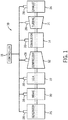
- FIG. 1 is a block diagram of a power generation system (e.g., a gas turbine) 10 having a compressor 12, combustor 14, turbine 16, and a controller 18, in accordance with an embodiment of the present disclosure.
- An intake duct 20 may feed ambient air to the compressor 12.
- the intake 20 may include ducts, filters, screens, and/or sound-absorbing devices that contribute to pressure loss of the ambient air flowing through the intake 20 into inlet guide vanes 22.
- An exhaust duct 24 may include sound-absorbing materials and emission control devices that apply a backpressure to the turbine 16. The amount of intake pressure loss and back pressure may vary over time due to the addition of components to and dust and dirt clogging the intake duct 20 and the exhaust duct 24.
- the turbine 16 may drive a generator 26 that produces electrical power.
- the operation of the gas turbine 10 may be monitored by one or more sensors 28 that may detect various observable conditions of one or more components of the gas turbine 10 (e.g., the generator 26, the intake 20, etc.) and/or the ambient environment.
- a plurality of redundant sensors may be used to measure the same measured condition.
- a plurality of redundant temperature sensors 28 may monitor ambient temperature surrounding the gas turbine 10, compressor discharge temperature, turbine exhaust gas temperature, and other temperature measurements of the gas stream through the gas turbine 10.
- a plurality of redundant pressure sensors 28 may monitor ambient pressure, and static and dynamic pressure levels at the intake duct 20, exhaust duct 24, and/or at other locations in the gas stream through the gas turbine 10.
- a plurality of redundant humidity sensors 28 may measure ambient humidity in the intake duct 20.
- a plurality of redundant sensors 28 may also include flow sensors, speed sensors, flame detector sensors, valve position sensors, guide vane angle sensors, or the like, that sense various parameters pertinent to the operation of gas turbine 10.
- a "parameter” refers to a measurable and/or estimable quality that can be used to define an operating condition of the gas turbine 10, such as temperature, pressure, gas flow, or the like, at defined locations in the gas turbine 10. Some parameters are measured (i.e., sensed) and are directly known. Other parameters are estimated by a model and are indirectly known. The measured and estimated parameters may be used to represent a given turbine operating state.
- the controller 18 may be a computer system having a processor(s) (e.g., a microprocessor(s)) that may execute software programs to control the operation of the gas turbine 10 using sensor inputs and instructions from human operators.
- the processor may include multiple microprocessors, one or more "general-purpose" microprocessors, one or more special-purpose microprocessors, and/or one or more application specific integrated circuits (ASICS), or some combination thereof.
- ASICS application specific integrated circuits
- the processor may include one or more reduced instruction set (RISC) processors.
- the controller 18 may be coupled to a memory device that may store information such as control software, look up tables, configuration data, etc. In some embodiments, the processor and/or the memory device may be external to the controller 18.
- the memory device may include a tangible, non-transitory, machine-readable-medium, such as a volatile memory (e.g., a random access memory (RAM)) and/or a nonvolatile memory (e.g., a read-only memory (ROM)).
- a volatile memory e.g., a random access memory (RAM)
- a nonvolatile memory e.g., a read-only memory (ROM)
- the memory device may store a variety of information and may be used for various purposes.
- the memory device may store machine-readable and/or processor-executable instructions (e.g., firmware or software) for the processor to execute, such as instructions for controlling the gas turbine 10.
- the storage device(s) e.g., nonvolatile storage
- the storage device(s) may store data (e.g., position data, identification data, etc.), instructions (e.g., software or firmware for controlling the haul vehicle, etc.), and any other suitable data.
- the controller 18 may generate commands to adjust valves of the combustor 14 that regulate the fuel flow, adjust inlet guide vanes 22, and activate other control effectors in order to control the gas turbine operation appropriately as indicated by the parameters. (e.g., setting desired exhaust temperatures or combustor fuel splits).
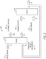
- FIG. 2 is a high-level block diagram 38 of a model 40 for simulating, in real-time, several operating parameters of the gas turbine 10, in accordance with an embodiment of the present disclosure.
- the model 40 may be an adaptive real-time engine simulation model (ARES).
- the gas turbine 10 may have several observable parameters that are referred to as model inputs (u) 42.
- the model inputs 42 may be directly measured by sensors and may include, for example, ambient conditions, angle of the inlet guide vanes 22, amount of fuel flowing to the combustor 14, rotational speed of the gas turbine 10, and the like.
- the model inputs 42 are exemplary and are provided to illustrate that sensed inputs are collected. The specific sensed model inputs are not material to this disclosure and will depend on the control system and available sensors at a particular gas turbine installation.
- the model inputs (u) 42 are input to the model 40 of the gas turbine 10.
- the model inputs 42 are applied by the model 40 to generate output values of the model 40 corresponding to simulated operating parameters of the gas turbine 10.
- the model outputs include primary outputs ( ⁇ ) 44 that may be compared to corresponding measured operating parameters of the gas turbine 10.
- the modeled outputs may also include extended modeled outputs ( ⁇ ext.) 48 that predict gas turbine parameters that are not directly measured (e.g., desired fuel flow rate).
- the extended modeled outputs 48 may be used by the controller 18 to operate the gas turbine 10, such as by applying a desired fuel flow rate to control an extended output parameter to maintain within a predefined limit.
- the primary outputs 44 and their corresponding measured operating parameters may include, but are not limited to, generator or power output, exhaust temperature (e.g., turbine exhaust temperature), compressor condition (e.g., compressor pressure ratio), and the like, or any combination thereof.
- the primary outputs 44 and the filter inputs 46 are provided to an error correction system or filter 50 (e.g., a Kalman filter gain matrix) that automatically and regularly adjusts or tunes the model 40 to more accurately fit the modeled output 44 to the measured filter inputs 46 of the gas turbine 10.
- the filter 50 adjusts or tunes the model 40 to fit one or more modeled output 44 of the model 40 to one or more measured filter inputs 46 of the gas turbine 10.
- the modeled outputs 44, 48 may predict gas turbine states that may be used for control, schedule maintenance for, and predict the performance of the gas turbine 10.
- the primary outputs ( ⁇ ) 44 of the model may be, for example, a modeled power output (e.g., to the generator 26), a modeled exhaust temperature, modeled compressor conditions, and the like.
- the number and particular parameters corresponding to the primary outputs 44 may vary between different gas turbine models. Further, the primary outputs 44 may vary during operation of the gas turbine 10.
- Each of the primary outputs 44 correspond to a measured (e.g., sensed) filter input (y) 46, such as an actual power output, exhaust temperature, compressor condition, and the like.
- the filter inputs 46 are based on one or more output signals of sensors monitoring a corresponding actual parameter of the gas turbine 10. Multiple redundant sensors may observe each of the parameters. The parameters are selected based on the specific control system for a gas turbine 10 and available sensors.
- the model 40 may be a computer-generated model of the gas turbine 10.
- the model 40 may be an arrangement of mathematical representations of the primary outputs 44 and extended outputs 48. Each of these representations may rely on input values (e.g., model inputs 42), to generate an estimated value of a modeled output parameter (e.g., 44, 48).
- the mathematical representations may generate a surrogate output parameter value (e.g., 44, 48) that may be used in circumstances where a measured parameter value is not available.
- the model 40 may be a physics-based aero-thermodynamic computer model, a regression-fit model, neural-net model, or other suitable computer model of a power generation system.
- the primary outputs 44 may be compared to the measured filter inputs 46 to generate a difference signal.
- the filter inputs 46 (y) are input into the filter 50 to tune the model 40.
- the primary outputs 44 and filter inputs 46 may be normalized to generate normalized modeled outputs, which may then be compared to generate the difference signal.
- the difference signal may indicate an error of a modeled output parameter with respect to the corresponding measured parameter.
- there is at least one difference signal corresponding to each of the primary outputs 44 and there may be a difference signal corresponding to each of the redundant sensors 28 measuring a particular parameter.
- the error correction system may still operate and tune the model 40 based on other filter inputs 46 that are available.
- the filter 50 may receive one or more of the difference signals and generate one or more correction factor adjustments 52 (e.g., component performance multipliers) of the gas turbine model 40 which may be used to tune the model 40.
- the correction factor adjustment 52 may correspond to a parameter of the gas turbine 10 (e.g., compressor airflow).
- the filter 50 may use partial derivative analysis and/or normalization to determine a matrix of optimal tuning or gain values to be applied to the difference signals. The matrix may then generate the correction factor adjustments 52, which may then be applied to the model 40.
- model 40 may include other sources of variation in addition to the tuning parameters, such as machine-to-machine manufacturing variation in the gas turbine 10, degradation of the gas turbine 10 over time, errors in the base model, errors that correspond to ambient and operating conditions, uncertainty and errors in inputs to the model 40, and the like.
- tuning parameters such as machine-to-machine manufacturing variation in the gas turbine 10, degradation of the gas turbine 10 over time, errors in the base model, errors that correspond to ambient and operating conditions, uncertainty and errors in inputs to the model 40, and the like.
- quantifying the degradation of the gas turbine 10 over time based solely on tuning parameters may be complicated by the contribution of these multiple sources of variation.
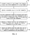
- FIG. 3 is a flowchart of a method 60 for quantifying degradation of a power generation system (e.g., the gas turbine 10) and account for at least some of the additional sources of variation, in accordance with an embodiment of the present disclosure.
- the controller 18 may perform the method 60, but it should be noted that any suitable computing system may perform method 60.
- the controller 18 generates (block 61) a model 40 of the gas turbine 10 that estimates a value for a first parameter of the gas turbine 10.
- the first parameter may be a primary output 44 estimated by the model 40 of FIG. 2 (e.g., the adaptive real-time engine simulation model (ARES)).
- the controller 18 may estimate a compressor discharge pressure of the gas turbine 10 by generating the model 40 of the gas turbine 10.
- the controller 18 then receives (block 62) a measured value of the first parameter.
- the first parameter may be a filter input 46 measured by one or more sensors of the gas turbine 10.
- the controller 18 may measure the compressor discharge pressure of the gas turbine 10 by receiving information from one or more sensors of the gas turbine 10 related to compressor pressure.
- the controller 18 adjusts or tunes (block 64) a correction factor 52 of the model 40, such that the estimated value of the first parameter output by the model 40 (from block 61) is approximately equal or matches the measured value of the parameter (from block 62).
- the controller 18 may adjust the correction factor 52 such that the estimated value of the primary output 44 output by the model 40 is approximately equal or matches the measured value of the filter input 46.
- the controller 18 may match the primary output 44 value corresponding to the compressor discharge pressure (a modeled value) to the filter input 46 value corresponding to the compressor discharge pressure (a measured value) by adjusting a correction factor 52 corresponding to a compressor airflow.
- the present example adjusts one correction factor 52, but other embodiments of the present disclosure include adjusting more than one correction factor 52.
- the controller 18 generates (block 66) a transfer function that represents the correction factor adjustment 52 as a function of a second parameter of the gas turbine 10.
- the second parameter is a relevant measured parameter of the gas turbine 10 that, when varied, may result in a change in the model 40 such that the estimated value of the first parameter may also change.
- the second parameter is the model input 42.
- the second parameter may be a relevant measured parameter of the gas turbine 10 that is not the model input 42.
- a transfer function is a mathematical representation expressing one or more outputs of a system as a function of one or more inputs of the system.
- the second parameter may be a compressor pressure ratio
- the transfer function as shown in Equation 1 may similarly be applied to other correction factor adjustments 52.
- the transfer function may be generated using multiple values in time for the correction factor adjustment 52 and the relevant measured parameter(s) (as determined in block 62).
- the transfer function may be generated and/or adjusted by using a fit routine to determine the values of constants k 1 , k 2 , and k 3 .
- the fit routine is used to determine one or more values of one or more constants of the transfer function.
- the controller 18 may then display (block 68) the transfer function to previously generated transfer functions to quantify degradation of the gas turbine 10.
- the controller 18 may store transfer functions that were previously generated in a memory device coupled to the controller 18.
- the controller 18 may display the current transfer function along with the saved and previously generated transfer functions.
- the controller 18 compares the transfer function to one or more previously generated transfer functions by comparing one or more reference points of the transfer function to one or more corresponding reference points associated with the one or more previously generated transfer functions. In this manner, the controller 18 may quantify degradation of the gas turbine 10.
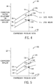
- FIG. 4 is a plot 80 of transfer functions for the correction factor adjustment 52 of the compressor airflow in the gas turbine 10, in accordance with an embodiment of the present disclosure.
- the horizontal axis 82 represents the compressor pressure ratio that corresponds to the second parameter, compressor pressure ratio
- the vertical axis 84 represents the correction factor adjustment 52 of the compressor airflow.
- Transfer functions 86, 88, 90 are plotted representing condition of the gas turbine 10 at three different times: when the gas turbine 10 is new and clean (as depicted by transfer function 86); the gas turbine 10 operating after 1000 hours of operation (transfer function 88); and the gas turbine 10 operating after 2000 hours of operation (transfer function 90).
- Each transfer function 86, 88, 90 has been generated as discussed in block 68 and represents a range of correction factor adjustments of compressor airflow as a function of a range of compressor pressure ratios during different times of operation by the gas turbine 10.
- Quantifying degradation of the gas turbine 10 may be achieved by viewing and/or comparing the transfer functions at one or more reference points defined by values of the second parameter (e.g., the compressor pressure ratio 82) of the transfer function.
- the second parameter e.g., the compressor pressure ratio 82
- the change in airflow over the time of operation of the gas turbine 10 may impact operational points of the gas turbine 10 that are based on control strategy.
- a typical assessment of degradation of the gas turbine 10 may result in the open circles in 100, 102, 104, which illustrate that the operating condition (i.e., compressor pressure ratio) is changing over time as the result of the degradation coupled with the control strategy.
- compressor degradation may result in a shift in the operation of the gas turbine 10
- comparison of the compressor airflow at the operational condition over time may not be a reliable representation of compressor degradation alone.
- the comparison of the open circles 100, 102, 104 captures compressor degradation, but may be confounded by the shift in the operating condition.
- Using the transfer function as described in the present disclosure to filter out the shift in the operating condition may segregate the compressor airflow loss over time due to compressor fouling/degradation from the change in compressor airflow due to the change in operating conditions.
- degradation of the gas turbine 10 after 1000 hours of operation is evidenced by the difference between the correction factor adjustment for compressor airflow after 1000 hours of operation 94 and when the gas turbine 10 is new and clean 92, at a certain compressor pressure ratio value 98.
- Degradation of the gas turbine 10 after 2000 hours of operation is evidenced by the difference between the correction factor adjustment after 2000 hours of operation 96 and when the gas turbine 10 is new and clean 92, at the certain compressor pressure ratio value 98.
- the transfer function which is based on multiple data points, the contribution of other sources of variation, such as uncertainty and errors in inputs to the model 40, and the like, when quantifying degradation of the gas turbine 10, may be filtered out.
- the transfer function the effect of other sources of variation on the data points 92, 94, 96 may be reduced, resulting in greater accuracy.
- Variation due to machine to machine degradation and errors in the base model are filtered as a result of the construction of the transfer functions, and the effect of these variations may be reduced in the computation of degradation by a relative comparison of transfer functions.
- using the transfer function as described above results in quantifying degradation of the gas turbine with a higher degree of accuracy
- the model inputs 42 which may represent the operating conditions described above, and the transfer functions 86, 88, 90, corresponding to the correction factor adjustment 52, may be used to generate and run the model 40 (e.g., the ARES model) of the gas turbine 10 and estimate an output of the gas turbine.
- FIG. 5 is a plot 120 of transfer functions for compressor airflow in the gas turbine 10, in accordance with an embodiment of the present disclosure.
- the model 40 estimates an extended modeled output 48, the compressor air flow, for various gas turbine operating conditions across the typical range compressor pressure ratio values during normal operation of the gas turbine. 10.
- the horizontal axis 122 represents the compressor pressure ratio which corresponds to the second parameter
- the vertical axis 124 represents the compressor airflow (that corresponds to an extended modeled output 48).
- Transfer functions 126, 128, 130 are plotted representing the operating conditions of the gas turbine 10 at three different times: the gas turbine 10 new and clean (as depicted by transfer function 126); the gas turbine 10 operating after 1000 hours of operation (transfer function 128); and the gas turbine 10 operating after 2000 hours of operation (transfer function 130).
- Each transfer function 126, 128, 130 has been generated as discussed in block 68 and represents a range of compressor airflow values as a function of a range of compressor pressure ratios during different times of operation by the gas turbine 10.
- a typical assessment of degradation of the gas turbine 10 may result in the open circles in FIG. 5 , 140, 142, 144, which illustrate that the operating condition (i.e., compressor pressure ratio) is changing over time as the result of the degradation coupled with the control strategy.
- the comparison of the open circles 140, 142, 144 captures compressor degradation, but may be confounded by the shift in the operating condition.
- Using the transfer function as described in the present disclosure to filter out the shift in the operating condition may segregate the compressor airflow loss over time due to compressor fouling/degradation from the change in compressor airflow due to the change in operating conditions.
- degradation of the gas turbine 10 after 1000 hours of operation is evidenced by the difference between the compressor airflow value after 1000 hours of operation 134 and when the gas turbine 10 is new and clean 132, at a certain compressor pressure ratio value 138.
- Degradation of the gas turbine 10 after 2000 hours of operation is evidenced by the difference between the compressor airflow value after 2000 hours of operation 136 and when the gas turbine 10 is new and clean 132, at the certain compressor pressure ratio value 138.
- the controller 18 may control the gas turbine 10 based on the degradation of the gas turbine 10. For example, a threshold degradation value may be determined or selected, wherein, when the degradation of the gas turbine 10 exceeds the threshold degradation value, the controller 18 may schedule maintenance of the gas turbine 10 and/or send an alert or message to a computing system.
- the computing system may monitor the gas turbine 10, monitor alerts or messages of industrial systems or devices, and/or enable communications to users associated with the gas turbine 10.
- the maintenance may include cleaning and/or restoring components of the compressor 12, intake duct 20, and/or inlet guide vanes 22 (e.g., via a compressor water wash).
- the controller 18 may initiate a compressor wash cycle for the gas turbine 10 based at least in part on the degradation of the gas turbine 10.
- the controller 18 may reduce output of the gas turbine 10 until the degradation of the gas turbine 10 is above the threshold degradation value.
- Technical effects of the subject matter disclosed herein include, but are not limited to, receiving a measured value of a parameter of a power generation system that is estimated by a model of a control system of the power generation system.
- the power generation system may include a gas turbine system, steam turbine system, wind turbine system, hydroturbine system, combustion engine, hydraulic engine, electric generator, and the like.
- the model may be an adaptive real-time engine simulation model.
- Technical effects also include adjusting a model input of the model such that a modeled value of the parameter is approximately equal to the measured value of the parameter.
- the model input may be adjusted such that the resulting modeled value matches the measured value.
- Technical effects further include generating a transfer function that represents the model input as a function of the parameter, based on the measured value of the parameter.
- the transfer function may be in the form of a quadratic formula, and may be generated or adjusted using a fit routine.
- Technical effects also include displaying the transfer function along with previously generated transfer functions to quantify degradation of the power generation system.
- the previously generated transfer functions are stored in a memory device of the control system of the power generation system. Based on the degradation of the power generation system, the control system may control the power generation system. For example, if the degradation surpasses a certain threshold, the control system may schedule maintenance or restoration of the power generation system to reduce degradation.
Landscapes
- Engineering & Computer Science (AREA)
- Physics & Mathematics (AREA)
- Automation & Control Theory (AREA)
- General Physics & Mathematics (AREA)
- Evolutionary Computation (AREA)
- Artificial Intelligence (AREA)
- General Engineering & Computer Science (AREA)
- Mechanical Engineering (AREA)
- Mathematical Physics (AREA)
- Computer Vision & Pattern Recognition (AREA)
- Medical Informatics (AREA)
- Software Systems (AREA)
- Health & Medical Sciences (AREA)
- Control Of Positive-Displacement Air Blowers (AREA)
- Supply And Distribution Of Alternating Current (AREA)
Applications Claiming Priority (1)
| Application Number | Priority Date | Filing Date | Title |
|---|---|---|---|
| US15/175,258 US9896960B2 (en) | 2016-06-07 | 2016-06-07 | Adaptive model-based method to quantify degradation of a power generation system |
Publications (3)
| Publication Number | Publication Date |
|---|---|
| EP3255512A2 true EP3255512A2 (de) | 2017-12-13 |
| EP3255512A3 EP3255512A3 (de) | 2018-01-03 |
| EP3255512B1 EP3255512B1 (de) | 2021-10-20 |
Family
ID=59093344
Family Applications (1)
| Application Number | Title | Priority Date | Filing Date |
|---|---|---|---|
| EP17173673.9A Active EP3255512B1 (de) | 2016-06-07 | 2017-05-31 | Auf adaptivem modell basierendes verfahren zur quantifizierung der verschlechterung eines stromerzeugungssystems |
Country Status (2)
| Country | Link |
|---|---|
| US (1) | US9896960B2 (de) |
| EP (1) | EP3255512B1 (de) |
Cited By (1)
| Publication number | Priority date | Publication date | Assignee | Title |
|---|---|---|---|---|
| EP3764183A1 (de) * | 2019-07-12 | 2021-01-13 | Siemens Aktiengesellschaft | Verwaltung des gesundheitszustands eines rotierenden systems |
Families Citing this family (5)
| Publication number | Priority date | Publication date | Assignee | Title |
|---|---|---|---|---|
| US10294869B2 (en) * | 2016-06-14 | 2019-05-21 | General Electric Company | System and method to enhance corrosion turbine monitoring |
| RU2707423C2 (ru) * | 2018-04-28 | 2019-11-26 | Общество С Ограниченной Ответственностью "Кловер Групп" | Способ и система для диагностирования промышленного объекта |
| US11667392B2 (en) * | 2019-06-20 | 2023-06-06 | Pratt & Whitney Canada Corp. | Method and system for operating a rotorcraft engine |
| US11592891B2 (en) * | 2019-10-15 | 2023-02-28 | Dell Products L.P. | System and method for diagnosing resistive shorts in an information handling system |
| CN111443595B (zh) * | 2020-04-04 | 2023-03-31 | 西北工业大学 | 基于健康退化的航空发动机增益调度控制器 |
Family Cites Families (13)
| Publication number | Priority date | Publication date | Assignee | Title |
|---|---|---|---|---|
| US7742904B2 (en) * | 2005-09-27 | 2010-06-22 | General Electric Company | Method and system for gas turbine engine simulation using adaptive Kalman filter |
| US7395188B1 (en) * | 2006-12-07 | 2008-07-01 | General Electric Company | System and method for equipment life estimation |
| GB0722398D0 (en) | 2007-11-15 | 2007-12-27 | Rolls Royce Plc | A method of monitoring a gas turbine engine |
| US8090456B2 (en) | 2008-11-03 | 2012-01-03 | United Technologies Corporation | System and method for design and control of engineering systems utilizing component-level dynamic mathematical model |
| US8639480B2 (en) * | 2010-09-20 | 2014-01-28 | General Electric Company | Methods and systems for modeling turbine operation |
| US20130024179A1 (en) * | 2011-07-22 | 2013-01-24 | General Electric Company | Model-based approach for personalized equipment degradation forecasting |
| US20130054213A1 (en) | 2011-08-23 | 2013-02-28 | General Electric Company | Process for adaptive modeling of performance degradation |
| US20130066615A1 (en) * | 2011-09-14 | 2013-03-14 | General Electric Company | System and method for simulating gas turbine operation |
| US8452515B2 (en) | 2011-09-15 | 2013-05-28 | General Electric Company | System and method for simulating a gas turbine compressor |
| US9411326B2 (en) * | 2012-08-21 | 2016-08-09 | General Electric Company | Plant control optimization system including visual risk display |
| US9422869B2 (en) * | 2013-03-13 | 2016-08-23 | General Electric Company | Systems and methods for gas turbine tuning and control |
| WO2015149928A2 (en) | 2014-03-31 | 2015-10-08 | Basf Se | Method and device for online evaluation of a compressor |
| US10047956B2 (en) | 2014-10-22 | 2018-08-14 | Honeywell International Inc. | Monitoring efficiency and operational mode changes of combustion equipment |
-
2016
- 2016-06-07 US US15/175,258 patent/US9896960B2/en active Active
-
2017
- 2017-05-31 EP EP17173673.9A patent/EP3255512B1/de active Active
Non-Patent Citations (1)
| Title |
|---|
| None |
Cited By (3)
| Publication number | Priority date | Publication date | Assignee | Title |
|---|---|---|---|---|
| EP3764183A1 (de) * | 2019-07-12 | 2021-01-13 | Siemens Aktiengesellschaft | Verwaltung des gesundheitszustands eines rotierenden systems |
| WO2021009042A1 (en) | 2019-07-12 | 2021-01-21 | Siemens Aktiengesellschaft | Managing health condition of a rotating system |
| US11933838B2 (en) | 2019-07-12 | 2024-03-19 | Siemens Aktiengesellschaft | Managing health condition of a rotating system |
Also Published As
| Publication number | Publication date |
|---|---|
| US20170350271A1 (en) | 2017-12-07 |
| US9896960B2 (en) | 2018-02-20 |
| EP3255512A3 (de) | 2018-01-03 |
| EP3255512B1 (de) | 2021-10-20 |
Similar Documents
| Publication | Publication Date | Title |
|---|---|---|
| EP3255512B1 (de) | Auf adaptivem modell basierendes verfahren zur quantifizierung der verschlechterung eines stromerzeugungssystems | |
| EP2562612B1 (de) | Verfahren und Systeme zur Gasturbinenmodellierung mit adaptivem Kalmanfilter | |
| EP2570616B1 (de) | System und Verfahren zur Simulierung eines Gasturbinenverdichters | |
| US20120070266A1 (en) | Turbo-machine temperature control | |
| JP2009162230A (ja) | タービンに対して代替制御方式を用いてリアルタイム比較を実現する方法及びシステム | |
| JP6937571B2 (ja) | スケーリングファクタを用いてパワー出力/放出パラメータを調節するガスタービンにおける複合確率的制御の応用、関連した制御システム、および方法 | |
| JP2017115867A (ja) | スケーリングファクタを用いてパワー出力/放出パラメータを調節するガスタービンにおける複合確率的制御、関連した制御システム、コンピュータプログラム製品、および方法 | |
| JP6900177B2 (ja) | パワー出力放出パラメータについてのガスタービンの調節におけるモデリング確率的制御、関連した制御システム、コンピュータプログラム製品、および方法 | |
| JP2017110644A (ja) | スケーリング係数を用いたパワー出力−排出量パラメータのためのガスタービンのチューニングにおける複合確率的制御の適用、関連する制御システム、コンピュータプログラム製品および方法 | |
| JP6906933B2 (ja) | スケーリングファクタを用いてパワー出力/放出パラメータを調節するガスタービンにおける複合確率的制御の応用、関連した制御システム、コンピュータプログラム製品、および方法 | |
| EP3373233A1 (de) | Wartungsplanung zur verringerung des verschleisses eines energieerzeugungssystems | |
| US9611791B2 (en) | Application of probabilistic control in gas turbine tuning for fuel flow-power output parameters, related control systems, computer program products and methods | |
| JP2017125495A (ja) | 出力−排出物パラメータに関するガスタービンの調節における装置特有の確率的制御、関連の制御システム、コンピュータプログラム製品、及び方法 | |
| US9599029B2 (en) | Application of probabilistic control in gas turbine tuning for fuel flow-emissions parameters, related control systems, computer program products and methods | |
| EP3373083A1 (de) | Stromerzeugungssystemsteuerung durch adaptives lernen | |
| US9803561B2 (en) | Power output and emissions based degraded gas turbine tuning and control systems, computer program products and related methods | |
| US9599026B2 (en) | Application of probabilistic control in gas turbine tuning for exhaust energy-power output parameters, related control systems, computer program products and methods | |
| US9599033B2 (en) | Application of probabilistic control in gas turbine tuning for fuel flow-exhaust energy parameters, related control systems, computer program products and methods | |
| US9771875B2 (en) | Application of probabilistic control in gas turbine tuning, related control systems, computer program products and methods | |
| US20160305333A1 (en) | Application of probabilistic control in gas turbine tuning for power output-exhaust energy parameters, related control systems, computer program products and methods | |
| US9599030B2 (en) | Application of probabilistic control in gas turbine tuning for exhaust energy-fuel flow parameters, related control systems, computer program products and methods | |
| US9599027B2 (en) | Application of probabilistic control in gas turbine tuning for emissions-exhaust energy parameters, related control systems, computer program products and methods | |
| US9599031B2 (en) | Application of probabilistic control in gas turbine tuning for power output-emissions parameters, related control systems, computer program products and methods | |
| US9599024B2 (en) | Application of probabilistic control in gas turbine tuning for exhaust energy-emissions parameters, related control systems, computer program products and methods |
Legal Events
| Date | Code | Title | Description |
|---|---|---|---|
| PUAI | Public reference made under article 153(3) epc to a published international application that has entered the european phase |
Free format text: ORIGINAL CODE: 0009012 |
|
| STAA | Information on the status of an ep patent application or granted ep patent |
Free format text: STATUS: THE APPLICATION HAS BEEN PUBLISHED |
|
| REG | Reference to a national code |
Ref country code: DE Ref legal event code: R079 Ref document number: 602017047789 Country of ref document: DE Free format text: PREVIOUS MAIN CLASS: G05B0017020000 Ipc: G05B0023020000 |
|
| PUAL | Search report despatched |
Free format text: ORIGINAL CODE: 0009013 |
|
| AK | Designated contracting states |
Kind code of ref document: A2 Designated state(s): AL AT BE BG CH CY CZ DE DK EE ES FI FR GB GR HR HU IE IS IT LI LT LU LV MC MK MT NL NO PL PT RO RS SE SI SK SM TR |
|
| AX | Request for extension of the european patent |
Extension state: BA ME |
|
| AK | Designated contracting states |
Kind code of ref document: A3 Designated state(s): AL AT BE BG CH CY CZ DE DK EE ES FI FR GB GR HR HU IE IS IT LI LT LU LV MC MK MT NL NO PL PT RO RS SE SI SK SM TR |
|
| AX | Request for extension of the european patent |
Extension state: BA ME |
|
| RIC1 | Information provided on ipc code assigned before grant |
Ipc: G05B 23/02 20060101AFI20171124BHEP Ipc: G05B 17/02 20060101ALI20171124BHEP |
|
| STAA | Information on the status of an ep patent application or granted ep patent |
Free format text: STATUS: REQUEST FOR EXAMINATION WAS MADE |
|
| 17P | Request for examination filed |
Effective date: 20180703 |
|
| RBV | Designated contracting states (corrected) |
Designated state(s): AL AT BE BG CH CY CZ DE DK EE ES FI FR GB GR HR HU IE IS IT LI LT LU LV MC MK MT NL NO PL PT RO RS SE SI SK SM TR |
|
| STAA | Information on the status of an ep patent application or granted ep patent |
Free format text: STATUS: EXAMINATION IS IN PROGRESS |
|
| 17Q | First examination report despatched |
Effective date: 20200715 |
|
| STAA | Information on the status of an ep patent application or granted ep patent |
Free format text: STATUS: EXAMINATION IS IN PROGRESS |
|
| GRAP | Despatch of communication of intention to grant a patent |
Free format text: ORIGINAL CODE: EPIDOSNIGR1 |
|
| STAA | Information on the status of an ep patent application or granted ep patent |
Free format text: STATUS: GRANT OF PATENT IS INTENDED |
|
| INTG | Intention to grant announced |
Effective date: 20210531 |
|
| GRAS | Grant fee paid |
Free format text: ORIGINAL CODE: EPIDOSNIGR3 |
|
| GRAA | (expected) grant |
Free format text: ORIGINAL CODE: 0009210 |
|
| STAA | Information on the status of an ep patent application or granted ep patent |
Free format text: STATUS: THE PATENT HAS BEEN GRANTED |
|
| AK | Designated contracting states |
Kind code of ref document: B1 Designated state(s): AL AT BE BG CH CY CZ DE DK EE ES FI FR GB GR HR HU IE IS IT LI LT LU LV MC MK MT NL NO PL PT RO RS SE SI SK SM TR |
|
| REG | Reference to a national code |
Ref country code: GB Ref legal event code: FG4D |
|
| REG | Reference to a national code |
Ref country code: CH Ref legal event code: EP |
|
| REG | Reference to a national code |
Ref country code: IE Ref legal event code: FG4D |
|
| REG | Reference to a national code |
Ref country code: DE Ref legal event code: R096 Ref document number: 602017047789 Country of ref document: DE |
|
| REG | Reference to a national code |
Ref country code: AT Ref legal event code: REF Ref document number: 1440444 Country of ref document: AT Kind code of ref document: T Effective date: 20211115 |
|
| REG | Reference to a national code |
Ref country code: LT Ref legal event code: MG9D |
|
| REG | Reference to a national code |
Ref country code: NL Ref legal event code: MP Effective date: 20211020 |
|
| REG | Reference to a national code |
Ref country code: AT Ref legal event code: MK05 Ref document number: 1440444 Country of ref document: AT Kind code of ref document: T Effective date: 20211020 |
|
| PG25 | Lapsed in a contracting state [announced via postgrant information from national office to epo] |
Ref country code: RS Free format text: LAPSE BECAUSE OF FAILURE TO SUBMIT A TRANSLATION OF THE DESCRIPTION OR TO PAY THE FEE WITHIN THE PRESCRIBED TIME-LIMIT Effective date: 20211020 Ref country code: LT Free format text: LAPSE BECAUSE OF FAILURE TO SUBMIT A TRANSLATION OF THE DESCRIPTION OR TO PAY THE FEE WITHIN THE PRESCRIBED TIME-LIMIT Effective date: 20211020 Ref country code: FI Free format text: LAPSE BECAUSE OF FAILURE TO SUBMIT A TRANSLATION OF THE DESCRIPTION OR TO PAY THE FEE WITHIN THE PRESCRIBED TIME-LIMIT Effective date: 20211020 Ref country code: BG Free format text: LAPSE BECAUSE OF FAILURE TO SUBMIT A TRANSLATION OF THE DESCRIPTION OR TO PAY THE FEE WITHIN THE PRESCRIBED TIME-LIMIT Effective date: 20220120 Ref country code: AT Free format text: LAPSE BECAUSE OF FAILURE TO SUBMIT A TRANSLATION OF THE DESCRIPTION OR TO PAY THE FEE WITHIN THE PRESCRIBED TIME-LIMIT Effective date: 20211020 |
|
| PG25 | Lapsed in a contracting state [announced via postgrant information from national office to epo] |
Ref country code: IS Free format text: LAPSE BECAUSE OF FAILURE TO SUBMIT A TRANSLATION OF THE DESCRIPTION OR TO PAY THE FEE WITHIN THE PRESCRIBED TIME-LIMIT Effective date: 20220220 Ref country code: SE Free format text: LAPSE BECAUSE OF FAILURE TO SUBMIT A TRANSLATION OF THE DESCRIPTION OR TO PAY THE FEE WITHIN THE PRESCRIBED TIME-LIMIT Effective date: 20211020 Ref country code: PT Free format text: LAPSE BECAUSE OF FAILURE TO SUBMIT A TRANSLATION OF THE DESCRIPTION OR TO PAY THE FEE WITHIN THE PRESCRIBED TIME-LIMIT Effective date: 20220221 Ref country code: PL Free format text: LAPSE BECAUSE OF FAILURE TO SUBMIT A TRANSLATION OF THE DESCRIPTION OR TO PAY THE FEE WITHIN THE PRESCRIBED TIME-LIMIT Effective date: 20211020 Ref country code: NO Free format text: LAPSE BECAUSE OF FAILURE TO SUBMIT A TRANSLATION OF THE DESCRIPTION OR TO PAY THE FEE WITHIN THE PRESCRIBED TIME-LIMIT Effective date: 20220120 Ref country code: NL Free format text: LAPSE BECAUSE OF FAILURE TO SUBMIT A TRANSLATION OF THE DESCRIPTION OR TO PAY THE FEE WITHIN THE PRESCRIBED TIME-LIMIT Effective date: 20211020 Ref country code: LV Free format text: LAPSE BECAUSE OF FAILURE TO SUBMIT A TRANSLATION OF THE DESCRIPTION OR TO PAY THE FEE WITHIN THE PRESCRIBED TIME-LIMIT Effective date: 20211020 Ref country code: HR Free format text: LAPSE BECAUSE OF FAILURE TO SUBMIT A TRANSLATION OF THE DESCRIPTION OR TO PAY THE FEE WITHIN THE PRESCRIBED TIME-LIMIT Effective date: 20211020 Ref country code: GR Free format text: LAPSE BECAUSE OF FAILURE TO SUBMIT A TRANSLATION OF THE DESCRIPTION OR TO PAY THE FEE WITHIN THE PRESCRIBED TIME-LIMIT Effective date: 20220121 Ref country code: ES Free format text: LAPSE BECAUSE OF FAILURE TO SUBMIT A TRANSLATION OF THE DESCRIPTION OR TO PAY THE FEE WITHIN THE PRESCRIBED TIME-LIMIT Effective date: 20211020 |
|
| REG | Reference to a national code |
Ref country code: DE Ref legal event code: R097 Ref document number: 602017047789 Country of ref document: DE |
|
| PG25 | Lapsed in a contracting state [announced via postgrant information from national office to epo] |
Ref country code: SM Free format text: LAPSE BECAUSE OF FAILURE TO SUBMIT A TRANSLATION OF THE DESCRIPTION OR TO PAY THE FEE WITHIN THE PRESCRIBED TIME-LIMIT Effective date: 20211020 Ref country code: SK Free format text: LAPSE BECAUSE OF FAILURE TO SUBMIT A TRANSLATION OF THE DESCRIPTION OR TO PAY THE FEE WITHIN THE PRESCRIBED TIME-LIMIT Effective date: 20211020 Ref country code: RO Free format text: LAPSE BECAUSE OF FAILURE TO SUBMIT A TRANSLATION OF THE DESCRIPTION OR TO PAY THE FEE WITHIN THE PRESCRIBED TIME-LIMIT Effective date: 20211020 Ref country code: EE Free format text: LAPSE BECAUSE OF FAILURE TO SUBMIT A TRANSLATION OF THE DESCRIPTION OR TO PAY THE FEE WITHIN THE PRESCRIBED TIME-LIMIT Effective date: 20211020 Ref country code: DK Free format text: LAPSE BECAUSE OF FAILURE TO SUBMIT A TRANSLATION OF THE DESCRIPTION OR TO PAY THE FEE WITHIN THE PRESCRIBED TIME-LIMIT Effective date: 20211020 Ref country code: CZ Free format text: LAPSE BECAUSE OF FAILURE TO SUBMIT A TRANSLATION OF THE DESCRIPTION OR TO PAY THE FEE WITHIN THE PRESCRIBED TIME-LIMIT Effective date: 20211020 |
|
| PLBE | No opposition filed within time limit |
Free format text: ORIGINAL CODE: 0009261 |
|
| STAA | Information on the status of an ep patent application or granted ep patent |
Free format text: STATUS: NO OPPOSITION FILED WITHIN TIME LIMIT |
|
| 26N | No opposition filed |
Effective date: 20220721 |
|
| PG25 | Lapsed in a contracting state [announced via postgrant information from national office to epo] |
Ref country code: AL Free format text: LAPSE BECAUSE OF FAILURE TO SUBMIT A TRANSLATION OF THE DESCRIPTION OR TO PAY THE FEE WITHIN THE PRESCRIBED TIME-LIMIT Effective date: 20211020 |
|
| PG25 | Lapsed in a contracting state [announced via postgrant information from national office to epo] |
Ref country code: SI Free format text: LAPSE BECAUSE OF FAILURE TO SUBMIT A TRANSLATION OF THE DESCRIPTION OR TO PAY THE FEE WITHIN THE PRESCRIBED TIME-LIMIT Effective date: 20211020 |
|
| REG | Reference to a national code |
Ref country code: CH Ref legal event code: PL |
|
| REG | Reference to a national code |
Ref country code: BE Ref legal event code: MM Effective date: 20220531 |
|
| GBPC | Gb: european patent ceased through non-payment of renewal fee |
Effective date: 20220531 |
|
| PG25 | Lapsed in a contracting state [announced via postgrant information from national office to epo] |
Ref country code: MC Free format text: LAPSE BECAUSE OF FAILURE TO SUBMIT A TRANSLATION OF THE DESCRIPTION OR TO PAY THE FEE WITHIN THE PRESCRIBED TIME-LIMIT Effective date: 20211020 Ref country code: LU Free format text: LAPSE BECAUSE OF NON-PAYMENT OF DUE FEES Effective date: 20220531 Ref country code: LI Free format text: LAPSE BECAUSE OF NON-PAYMENT OF DUE FEES Effective date: 20220531 Ref country code: CH Free format text: LAPSE BECAUSE OF NON-PAYMENT OF DUE FEES Effective date: 20220531 |
|
| PG25 | Lapsed in a contracting state [announced via postgrant information from national office to epo] |
Ref country code: IE Free format text: LAPSE BECAUSE OF NON-PAYMENT OF DUE FEES Effective date: 20220531 Ref country code: FR Free format text: LAPSE BECAUSE OF NON-PAYMENT OF DUE FEES Effective date: 20220531 |
|
| PG25 | Lapsed in a contracting state [announced via postgrant information from national office to epo] |
Ref country code: IT Free format text: LAPSE BECAUSE OF FAILURE TO SUBMIT A TRANSLATION OF THE DESCRIPTION OR TO PAY THE FEE WITHIN THE PRESCRIBED TIME-LIMIT Effective date: 20211020 Ref country code: GB Free format text: LAPSE BECAUSE OF NON-PAYMENT OF DUE FEES Effective date: 20220531 Ref country code: BE Free format text: LAPSE BECAUSE OF NON-PAYMENT OF DUE FEES Effective date: 20220531 |
|
| PGFP | Annual fee paid to national office [announced via postgrant information from national office to epo] |
Ref country code: DE Payment date: 20230419 Year of fee payment: 7 |
|
| REG | Reference to a national code |
Ref country code: DE Ref legal event code: R082 Ref document number: 602017047789 Country of ref document: DE Ref country code: DE Ref legal event code: R081 Ref document number: 602017047789 Country of ref document: DE Owner name: GENERAL ELECTRIC TECHNOLOGY GMBH, CH Free format text: FORMER OWNER: GENERAL ELECTRIC COMPANY, SCHENECTADY, NY, US |
|
| PG25 | Lapsed in a contracting state [announced via postgrant information from national office to epo] |
Ref country code: HU Free format text: LAPSE BECAUSE OF FAILURE TO SUBMIT A TRANSLATION OF THE DESCRIPTION OR TO PAY THE FEE WITHIN THE PRESCRIBED TIME-LIMIT; INVALID AB INITIO Effective date: 20170531 |
|
| PG25 | Lapsed in a contracting state [announced via postgrant information from national office to epo] |
Ref country code: MK Free format text: LAPSE BECAUSE OF FAILURE TO SUBMIT A TRANSLATION OF THE DESCRIPTION OR TO PAY THE FEE WITHIN THE PRESCRIBED TIME-LIMIT Effective date: 20211020 Ref country code: CY Free format text: LAPSE BECAUSE OF FAILURE TO SUBMIT A TRANSLATION OF THE DESCRIPTION OR TO PAY THE FEE WITHIN THE PRESCRIBED TIME-LIMIT Effective date: 20211020 |