EP3255437B1 - Fault source parameter identification - Google Patents
Fault source parameter identification Download PDFInfo
- Publication number
- EP3255437B1 EP3255437B1 EP17175478.1A EP17175478A EP3255437B1 EP 3255437 B1 EP3255437 B1 EP 3255437B1 EP 17175478 A EP17175478 A EP 17175478A EP 3255437 B1 EP3255437 B1 EP 3255437B1
- Authority
- EP
- European Patent Office
- Prior art keywords
- air data
- data value
- parameters
- diagnostic
- aircraft
- Prior art date
- Legal status (The legal status is an assumption and is not a legal conclusion. Google has not performed a legal analysis and makes no representation as to the accuracy of the status listed.)
- Active
Links
- 238000013473 artificial intelligence Methods 0.000 claims description 84
- 238000000034 method Methods 0.000 claims description 35
- 230000015654 memory Effects 0.000 claims description 26
- 230000008569 process Effects 0.000 claims description 16
- 230000006870 function Effects 0.000 claims description 12
- 238000012545 processing Methods 0.000 claims description 12
- 238000012546 transfer Methods 0.000 claims description 10
- 238000013528 artificial neural network Methods 0.000 claims description 9
- 230000003068 static effect Effects 0.000 claims description 7
- 210000002569 neuron Anatomy 0.000 claims description 6
- RZVHIXYEVGDQDX-UHFFFAOYSA-N 9,10-anthraquinone Chemical compound C1=CC=C2C(=O)C3=CC=CC=C3C(=O)C2=C1 RZVHIXYEVGDQDX-UHFFFAOYSA-N 0.000 claims description 5
- 230000001133 acceleration Effects 0.000 claims description 3
- 239000000446 fuel Substances 0.000 claims description 3
- 238000004891 communication Methods 0.000 description 10
- 230000004044 response Effects 0.000 description 10
- 238000010586 diagram Methods 0.000 description 8
- 239000000523 sample Substances 0.000 description 7
- 238000012549 training Methods 0.000 description 3
- 238000001514 detection method Methods 0.000 description 2
- 230000007613 environmental effect Effects 0.000 description 2
- 238000002955 isolation Methods 0.000 description 2
- 230000007774 longterm Effects 0.000 description 2
- 230000003287 optical effect Effects 0.000 description 2
- 230000004308 accommodation Effects 0.000 description 1
- 230000006399 behavior Effects 0.000 description 1
- 230000008859 change Effects 0.000 description 1
- 238000013461 design Methods 0.000 description 1
- 230000002708 enhancing effect Effects 0.000 description 1
- 230000036541 health Effects 0.000 description 1
- 230000000977 initiatory effect Effects 0.000 description 1
- 239000000463 material Substances 0.000 description 1
- 239000000203 mixture Substances 0.000 description 1
- 238000012986 modification Methods 0.000 description 1
- 230000004048 modification Effects 0.000 description 1
- 230000000644 propagated effect Effects 0.000 description 1
- 230000000306 recurrent effect Effects 0.000 description 1
- 230000002123 temporal effect Effects 0.000 description 1
- 238000012360 testing method Methods 0.000 description 1
Images


Classifications
-
- G—PHYSICS
- G07—CHECKING-DEVICES
- G07C—TIME OR ATTENDANCE REGISTERS; REGISTERING OR INDICATING THE WORKING OF MACHINES; GENERATING RANDOM NUMBERS; VOTING OR LOTTERY APPARATUS; ARRANGEMENTS, SYSTEMS OR APPARATUS FOR CHECKING NOT PROVIDED FOR ELSEWHERE
- G07C5/00—Registering or indicating the working of vehicles
- G07C5/08—Registering or indicating performance data other than driving, working, idle, or waiting time, with or without registering driving, working, idle or waiting time
- G07C5/0808—Diagnosing performance data
-
- B—PERFORMING OPERATIONS; TRANSPORTING
- B64—AIRCRAFT; AVIATION; COSMONAUTICS
- B64C—AEROPLANES; HELICOPTERS
- B64C13/00—Control systems or transmitting systems for actuating flying-control surfaces, lift-increasing flaps, air brakes, or spoilers
- B64C13/24—Transmitting means
- B64C13/38—Transmitting means with power amplification
- B64C13/50—Transmitting means with power amplification using electrical energy
- B64C13/505—Transmitting means with power amplification using electrical energy having duplication or stand-by provisions
-
- B—PERFORMING OPERATIONS; TRANSPORTING
- B64—AIRCRAFT; AVIATION; COSMONAUTICS
- B64D—EQUIPMENT FOR FITTING IN OR TO AIRCRAFT; FLIGHT SUITS; PARACHUTES; ARRANGEMENTS OR MOUNTING OF POWER PLANTS OR PROPULSION TRANSMISSIONS IN AIRCRAFT
- B64D43/00—Arrangements or adaptations of instruments
-
- G—PHYSICS
- G01—MEASURING; TESTING
- G01P—MEASURING LINEAR OR ANGULAR SPEED, ACCELERATION, DECELERATION, OR SHOCK; INDICATING PRESENCE, ABSENCE, OR DIRECTION, OF MOVEMENT
- G01P13/00—Indicating or recording presence, absence, or direction, of movement
- G01P13/02—Indicating direction only, e.g. by weather vane
- G01P13/025—Indicating direction only, e.g. by weather vane indicating air data, i.e. flight variables of an aircraft, e.g. angle of attack, side slip, shear, yaw
-
- G—PHYSICS
- G01—MEASURING; TESTING
- G01P—MEASURING LINEAR OR ANGULAR SPEED, ACCELERATION, DECELERATION, OR SHOCK; INDICATING PRESENCE, ABSENCE, OR DIRECTION, OF MOVEMENT
- G01P21/00—Testing or calibrating of apparatus or devices covered by the preceding groups
- G01P21/02—Testing or calibrating of apparatus or devices covered by the preceding groups of speedometers
- G01P21/025—Testing or calibrating of apparatus or devices covered by the preceding groups of speedometers for measuring speed of fluids; for measuring speed of bodies relative to fluids
-
- G—PHYSICS
- G01—MEASURING; TESTING
- G01P—MEASURING LINEAR OR ANGULAR SPEED, ACCELERATION, DECELERATION, OR SHOCK; INDICATING PRESENCE, ABSENCE, OR DIRECTION, OF MOVEMENT
- G01P5/00—Measuring speed of fluids, e.g. of air stream; Measuring speed of bodies relative to fluids, e.g. of ship, of aircraft
- G01P5/14—Measuring speed of fluids, e.g. of air stream; Measuring speed of bodies relative to fluids, e.g. of ship, of aircraft by measuring differences of pressure in the fluid
- G01P5/16—Measuring speed of fluids, e.g. of air stream; Measuring speed of bodies relative to fluids, e.g. of ship, of aircraft by measuring differences of pressure in the fluid using Pitot tubes, e.g. Machmeter
Definitions
- air data computer 18 can transmit a time value (e.g., an absolute time such as GMT time, a relative time since power-up, or other time value) with first air data value 26 corresponding to a time at which the first set of parameters from sensor(s) 20 was received (or sensed) and utilized to generate first air data value 26.
- a time value e.g., an absolute time such as GMT time, a relative time since power-up, or other time value
- synthetic air data system 16 can identify a time (absolute or relative) at which first air data value 26 is received. Synthetic air data system 16 can utilize the time value for data synchronization and comparison with second air data value 28, as is further described below.
- Each of input nodes I 1 -I N corresponds to a different one of the plurality of input parameters 12A-12N.
- Each of internal nodes h 1 -h M applies a weight, bias, and transfer function (e.g., a sigmoid function) to each of input nodes I 1 -I N to generate intermediate outputs provided by internal nodes h 1 -h M .
- the intermediate outputs provided by internal nodes h 1 -h M are provided as inputs to output node O 1 .
- Output node O 1 applies predetermined weights, biases, and/or a transfer function to the intermediate outputs to generate second air data value 28.
- Each of diagnostic artificial intelligence networks 14A-14N utilizes a different set of internal nodes 34A-34N.
- Each set of internal nodes 34A-34N can be configured (e.g., trained) to correlate those of input parameters 12A-12N received at the corresponding input nodes to generate intermediate outputs at internal nodes 34A-34N that are provided to output nodes 36A-36N to generate diagnostic air data values 30A-30N.
- initiation of the processing of the second set of parameters through the plurality of diagnostic air data values may not be responsive to determining that the first air data value deviates from the second air data value by the threshold amount (i.e., Step 46). Rather, in such examples, the operation of Step 46 may be omitted, such that processing of the second set of parameters through the plurality of diagnostic artificial intelligence networks to generate the plurality of diagnostic air data values is performed without regard to deviation between the first air data value and the second air data value.
Description
- The present disclosure relates generally to air data systems, and more particularly to air data systems that can utilize artificial intelligence to generate air data outputs for an aircraft.
- Modern aircraft often incorporate air data systems that calculate air data outputs based on measured parameters collected from various sensors positioned about the aircraft. For instance, many modern aircraft utilize pneumatic air data probes that measure pitot pressure, static pressure, or other parameters of airflow across the probe. Such pneumatic air data probes often include one or more air data sensing ports, such as static pressure ports and/or total pressure (i.e., stagnation pressure) ports. A portion of air flowing over the probes is diverted to the ports that are pneumatically connected to pressure sensors that sense the atmospheric pressure outside the aircraft. Such measured pressures are usable for determining air data outputs, such as aircraft pressure altitude, altitude rate (e.g., vertical speed), airspeed, Mach number, angle of attack, angle of sideslip, or other air data outputs.
- To increase system reliability, aircraft manufacturers typically incorporate redundant (e.g., backup) systems that can provide outputs to consuming systems in the event that a primary system fails or is otherwise determined to be unreliable. For instance, many aircraft incorporate multiple (e.g., two, three, four, or more) pneumatic air data probes, certain of which are designated as backup systems for use when a primary system is deemed unreliable. In some cases, backup systems that utilize dissimilar design architectures and components as compared with a primary system can be desirable to reduce the chances of common mode failures between the primary and backup systems. Systems for identifying faults are disclosed in NAPOLITANO M R ET AL: "NEURAL-NETWORK-BASED SCHEME FOR SENSOR FAILURE DETECTION, IDENTIFICATION, AND ACCOMMODATION", JOURNAL OF GUIDANCE AND CONTROL AND DYNAMICS, AIAA, RESTON, VA, US, vol. 18, no. 6, 1 November 1995 (1995-11-01), pages 1280-1286 and
US 2010/100260 . - The invention provides a method as defined in
claim 1. - The invention also provides a system as defined in claim 9.
-
-
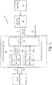
FIG. 1 is a schematic block diagram of an example system that processes a set of input parameters through a plurality of diagnostic artificial intelligence networks to identify a fault source parameter associated with a fault condition. -
FIG. 2 is a schematic diagram of an example artificial neural network that can be used to process input parameters to generate an air data value. -
FIG. 3 is a schematic diagram of a plurality of diagnostic artificial intelligence networks that each exclude a different one of a set of input parameters to generate a set of diagnostic air data values. -
FIG. 4 is a flow diagram illustrating example operations to process a set of input parameters through a plurality of diagnostic artificial intelligence networks to identify a fault source parameter associated with a fault condition. - As described herein, a system implementing techniques of this disclosure can compare air data values generated using mutually exclusive sets of input parameters to identify one or more of the input parameters as a fault source parameter associated with a fault condition. For example, the system can generate a first air data value based on a first set of parameters. The first set of parameters can include, e.g., measured pressure values (e.g., pitot pressure, static pressure, or other measured pressure values), optically-measured values, or other measured values that are usable to determine air data values, such as airspeed, altitude, angle of attack, angle of sideslip, or other air data values. The system can further generate a second air data value based on a second set of parameters that does not include any of the first set of parameters (i.e., mutually exclusive of the first set of parameters). For instance, the system can process the second set of parameters through an artificial intelligence network that is trained to generate the air data output value. The second set of parameters can include, among others, aircraft thrust parameters, aircraft engine throttle settings, flight control surface positions and/or surface loading parameters, aircraft remaining fuel weight and/or usage rates, aircraft weight, landing gear position (e.g., deployed or stowed), aircraft mass balance, and aircraft acceleration and/or angular rates (e.g., received from an inertial reference system). In some examples, the second set of parameters can include an air data parameter (e.g., the first air data value) generated using the first set of parameters.
- A deviation between the first and second air data values can be indicative of a fault condition associated with one or more of the input parameters. Accordingly, in response to identifying a deviation between the first and second air data values, the system can generate a set of diagnostic air data values by processing the second set of parameters through a plurality of diagnostic artificial intelligence networks, each excluding a different one of the second set of parameters and trained to generate the air data value. The system can therefore identify, based on agreement between the diagnostic air data values and the first air data value (i.e., generated based on the first set of input parameters that is mutually exclusive of the second set of input parameters), one or more of the second set of input parameters as a fault source parameter that is associated with a fault condition. For instance, in the event that the first air data value that is generated using the first set of input parameters (e.g., measured pressure parameters) deviates from the second air data value that is generated using the second set of input parameters by at least a threshold amount, the system can generate the plurality of diagnostic values using the plurality of artificial intelligence networks that each exclude a different one of the second set of input parameters. If, for example, the diagnostic air data value that is generated using a diagnostic artificial intelligence network that excludes, e.g., a left aileron position input parameter, agrees with the first air data parameter (e.g., is within a threshold deviation from the first air data value), the system can identify the left aileron position input parameter as a fault source parameter associated with a fault condition of, e.g., the left aileron position sensor. Accordingly, a system implementing techniques of this disclosure can enhance aircraft fault diagnostic operations, thereby helping to increase overall aircraft system reliability.
-
FIG. 1 is a schematic block diagram ofsystem 10 that processes a set ofinput parameters 12A-12N through a plurality of diagnosticartificial intelligence networks 14 to identify a fault source parameter associated with a fault condition. As illustrated inFIG. 1 ,system 10 includes syntheticair data system 16,air data computer 18, and one ormore sensors 20. Syntheticair data system 16 includes diagnosticartificial intelligence networks 14, syntheticartificial intelligence networks 22, andfault isolator 24. - Synthetic
air data system 16 receives firstair data value 26 fromair data computer 18 that generates firstair data value 26 based on measured values received from sensor(s) 20. Syntheticair data system 16 processesinput parameters 12A-12N through syntheticartificial intelligence network 22 to generate secondair data value 28.Fault isolator 24 compares firstair data value 26 with secondair data value 28 and, in certain examples, initiates processing ofinput parameters 12A-12N through diagnosticartificial intelligence networks 14 in response to an identified deviation between firstair data value 26 and secondair data value 28 to generate diagnosticair data values 30A-30N. As is further described below, each of diagnosticartificial intelligence networks 14 excludes a different one ofinput parameters 12A-12N.Fault isolator 24 compares diagnosticair data values 30A-30N to firstair data value 26.Fault isolator 24 determines whether one or more of diagnosticair data values 30A-30N agrees with (e.g., is within a threshold deviation from) firstair data value 26. In response to determining that one of diagnosticair data values 30A-30N agrees with firstair data value 26,fault isolator 24 identifies the one ofinput parameters 12A-12N that was excluded from the corresponding one of diagnosticartificial intelligence networks 14 during generation of the identified one of diagnosticair data values 30A-30N that agrees with firstair data value 26.Fault isolator 24 identifies the excluded one ofinput parameters 12A-12N as a fault source parameter that is associated with a fault condition. In response,fault isolator 24 can outputfault indication 32 including an identification of the fault parameter and/or data corresponding to the identified fault parameter. - While the example of
FIG. 1 is illustrated and described with respect to a single firstair data value 26 and a single secondair data value 28, aspects of this disclosure are not so limited. For instance,air data computer 18 can generate multiple air data values, each corresponding to a different air data value generated by a different syntheticartificial intelligence network 22 and different diagnostic air data values generated by differing diagnosticartificial intelligence networks 14. As such, techniques of this disclosure are applicable to multiple air data values (e.g., altitude, airspeed, angle of attack, angle of sideslip, or other air data values) that are generated based on multiple sets ofinput parameters 12A-12N and processed through a plurality of diagnostic artificial intelligence networks to identify one or more ofinput parameters 12A-12N as a fault source parameter that is associated with a fault condition. - Synthetic
air data system 16 can include one or more processors and computer-readable memory encoded with instructions that, when executed by the one or more processors, cause syntheticair data system 16 to operate in accordance with techniques described herein. Syntheticair data system 16, in some examples, can include one or more stand-alone electronic devices, such that syntheticair data system 16 is separate fromair data computer 18. In other examples, syntheticair data system 16 can be included in any one or more ofair data computer 18 and/or other aircraft systems, such that functionality attributed herein to syntheticair data system 16 is performed by and/or distributed among one or more electronic devices of such other systems. For instance, in some examples, air data computer 18 (or one or more air data computers substantially similar to air data computer 18) can implement functionality attributed herein to syntheticair data system 16. In other examples, any one or more portions of syntheticair data system 16 can be implemented in a different aircraft system, such as a prognostic health management (PHM) system that is configured to diagnose fault conditions and/or predict a remaining useful life of various aircraft system components. In general, syntheticair data system 16 includes one or more processors and computer-readable memory encoded with instructions that, when executed by the one or more processors, cause syntheticair data system 16 to processinput parameters 12A-12N through a plurality of diagnostic artificial intelligence networks to generate diagnosticair data values 30A-30N that are usable to identify one or more ofinput parameters 12A-12N as a fault source parameter that is associated with a fault condition. -
Air data computer 18 includes electrical components, such as one or more processors, computer-readable memory, or other electrical components configured to generate air data outputs (e.g., first air data value 26) corresponding to one or more operational states of an the associated aircraft. Non-limiting examples of such air data outputs include calibrated airspeed, true airspeed, Mach number, altitude (e.g., pressure altitude), angle of attack (i.e., an angle between oncoming airflow or relative wind and a reference line of a wing of the aircraft), vertical speed (e.g., altitude rate), and angle of sideslip (i.e., an angle between a direction of travel and a direction extending through a nose of the aircraft). While illustrated as including a singleair data computer 18, in other examples,system 10 can include two or moreair data computers 18. Similarly, while syntheticair data system 16 andair data computer 18 are illustrated in the example ofFIG. 1 as separate components, in other examples, syntheticair data system 16 andair data computer 18 can be implemented as a same component or integrated system. - Processor(s) of synthetic
air data system 16 andair data computer 18 can include any one or more of a microprocessor, a controller (e.g., microcontroller), a digital signal processor (DSP), an application specific integrated circuit (ASIC), a field-programmable gate array (FPGA), or other equivalent discrete or integrated logic circuitry. Processor(s) of syntheticair data system 16 and/orair data computer 18 can, in some examples, include and/or implement a clocking function that can be used for time synchronization of sensed parameters utilized to generate firstair data value 26 and secondair data value 28, as is further described below. Computer-readable memory of syntheticair data system 16 andair data computer 18 can be configured to store information within syntheticair data system 16 andair data computer 18 during operation. Such computer-readable memory, in some examples, is described as computer-readable storage media. In some examples, a computer-readable storage medium can include a non-transitory medium. The term "non-transitory" can indicate that the storage medium is not embodied in a carrier wave or a propagated signal. In certain examples, a non-transitory storage medium can store data that can, over time, change (e.g., in RAM or cache). In some examples, the computer-readable memory is a temporary memory, meaning that a primary purpose of the computer-readable memory is not long-term storage. Computer-readable memory, in some examples, includes and/or is described as volatile memory, meaning that the computer-readable memory does not maintain stored contents when power to syntheticair data system 16 orair data computer 18 is removed. Examples of volatile memories can include random access memories (RAM), dynamic random access memories (DRAM), static random access memories (SRAM), and other forms of volatile memories. In some examples, computer-readable memory is used to store program instructions for execution by one or more processors of syntheticair data system 16 andair data computer 18. Computer-readable memory, in one example, is used by software or applications executing on syntheticair data system 16 andair data computer 18 to temporarily store information during program execution. - Computer-readable memory of synthetic
air data system 16 andair data computer 18, in some examples, also includes one or more computer-readable storage media. Computer-readable storage media can be configured to store larger amounts of information than volatile memory. Computer-readable storage media can be configured for long-term storage of information. In some examples, computer-readable storage media include non-volatile storage elements. Examples of such non-volatile storage elements can include magnetic hard discs, optical discs, floppy discs, flash memories, or forms of electrically programmable memories (EPROM) or electrically erasable and programmable (EEPROM) memories. - Sensor(s) 20 can include any one or more sensing devices capable of sensing aircraft environmental and/or operating conditions that are usable for generating first
air data value 26. For instance, sensor(s) 20 can include one or more pressure sensors (e.g., transducers) configured for use in measuring static pressure and/or pitot pressure (e.g., total pressure) of airflow across a pitot-static probe or other air data sensing probe connected to an exterior of the aircraft. In some examples, sensor(s) 20 can include optical or other sensors capable of measuring aircraft environmental and/or operating conditions related to air data values (e.g., first air data value 26). In certain examples, sensor(s) 20 can include an aircraft angle of attack vane or other such sensor configured to rotate and align with a direction of airflow about the exterior of the aircraft to sense an angle of attack of the aircraft. -
Input parameters 12A-12N can include measured and/or calculated parameters indicative of an operational state of aircraft systems and/or components. Examples ofinput parameters 12A-12N include, but are not limited to, inputs corresponding to aircraft control surface position (e.g., ailerons, elevator, rudder, spoilerons, flaps, slats, or other control surfaces) and/or control surface loading, aircraft mass and/or mass balance (e.g., current and/or at a predefined time, such as at takeoff), remaining fuel weight, engine thrust parameters (e.g., engine N1, N2, EGT, throttle settings, or other thrust parameters), aircraft navigational information (e.g., aircraft position, heading, altitude, ground speed, airspeed, or other navigational information), air temperature information (e.g., static air temperature, total air temperature, outside air temperature, or other temperature information), aircraft acceleration and/or angular rate information (e.g., received from an IRS), landing gear position information (e.g., deployed, stowed, in transit, or other landing gear position information), or other aircraft system and/or component operational input parameters. In some examples,input parameters 12A-12N can include one or more air data parameters generated using input parameters received from sensor(s) 20, such as firstair data value 26 or other air data values. The set ofinput parameters 12A-12N can be mutually exclusive of those input parameters received from sensor(s) 20 and used to generate firstair data value 26. That is,input parameters 12A-12N, in certain examples, can include a set of input parameters usable by syntheticair data system 16 to generate secondair data value 28 via syntheticartificial intelligence network 22 that does not include any of the input parameters received byair data computer 18 from sensor(s) 20 to generate firstair data value 26. -
Air data computer 18, as illustrated inFIG. 1 , is operatively connected (e.g., electrically and/or communicatively connected) to sensor(s) 20 to receive a first set of sensed parameters from sensor(s) 20 for generation of firstair data value 26.Air data computer 18 is communicatively coupled to syntheticair data system 16 to transmit firstair data value 26 to syntheticair data system 16. In examples whereair data computer 18 implements one or more aspects of syntheticair data system 16, syntheticair data system 16 may receive firstair data value 26 via inter-process communications, such as via an inter-process communication data structure or other internal communications operations. In some examples,air data computer 18 can transmit a time value (e.g., an absolute time such as GMT time, a relative time since power-up, or other time value) with firstair data value 26 corresponding to a time at which the first set of parameters from sensor(s) 20 was received (or sensed) and utilized to generate firstair data value 26. In other examples, syntheticair data system 16 can identify a time (absolute or relative) at which firstair data value 26 is received. Syntheticair data system 16 can utilize the time value for data synchronization and comparison with secondair data value 28, as is further described below. - As further illustrated in
FIG. 1 , syntheticair data system 16 is configured to receiveinput parameters 12A-12N andoutput fault indication 32 via, e.g., an aircraft communications data bus or other communications network. For instance, syntheticair data system 16 can be configured to send and receive data on one or more aircraft communications data buses via, e.g., a defined communication protocol, such as the Aeronautical Radio, Incorporated (ARINC) 429 communication protocol or other defined protocol. Syntheticair data system 16 can receiveinput parameters 12A-12N via the communications data bus directly from transmitting aircraft systems (e.g., engine control systems, flight management computers, flight control computers) and/or from a data concentrator unit (DCU) or other aircraft communications management system. In some examples, any one or more ofinput parameters 12A-12N can include a time value, such as an absolute time (e.g., GMT time), a relative time since power-up, or other time value at which the respective one ofinput parameters 12A-12N was sensed. In certain examples, syntheticair data system 16 can associateinput parameters 12A-12N with a time value (e.g., absolute time value, relative time value, or other time value) at which syntheticair data system 16 receivesinput parameters 12A-12N. Syntheticair data system 16 can utilize the time values to time-synchronize firstair data value 26 and the set ofinput parameters 12A-12N that are utilized to generate secondair data value 28, as is further described below. Syntheticair data system 16 canoutput fault indication 32 via the aircraft data bus and/or directly to a consuming system, such as the DCU, a display device, a PHM controller, or other consuming system. - As illustrated in
FIG. 1 , syntheticair data system 16 includes syntheticartificial intelligence network 22, diagnosticartificial intelligence networks 14, andfault isolator 24. As is further described below, syntheticair data system 16 processesinput parameters 12A-12N through syntheticartificial intelligence network 22 to generate secondair data value 28. In addition, syntheticair data system 16 processesinput parameters 12A-12N through diagnosticartificial intelligence networks 14 to generate diagnostic air data values 30A-30N. Examples of syntheticartificial intelligence network 22 and diagnosticartificial intelligence networks 14 include artificial neural networks, probabilistic graphical models such as Bayesian networks, probabilistic classifiers and/or controllers (e.g., Gaussian mixture models), or other forms of artificial intelligence networks. As one example, syntheticartificial intelligence network 22 and each of diagnosticartificial intelligence networks 14 can be separate artificial neural networks, each having at least one internal layer of nodes (often referred to as a hidden layer of neurons) that apply one or more weights, biases, and/or transfer functions to inputparameters 12A-12N to correlateinput parameters 12A-12N to a common air data value (e.g., altitude, airspeed, Mach number, angle of attack, angle of sideslip, or other air data value). - In some examples, such as when synthetic
artificial intelligence network 22 and diagnosticartificial intelligence networks 14 are artificial neural networks, the weights, biases, and transfer functions of the hidden layers of neurons can be pre-defined (e.g., pre-trained via offline pre-training) and fixed, such that syntheticair data system 16 does not modify the weights, biases, and transfer functions during operation. In other examples, syntheticair data system 16 can incorporate an active training (or "learning") mode in which syntheticair data system 16 modifies the weights, biases, and transfer functions applied by the neurons of each network based on feedback of the generated air data value and a reference air data value. - In operation,
air data computer 18 receives a first set of input parameters from sensor(s) 20 and generates firstair data value 26 based on the first set of input parameters.Air data computer 18 communicates firstair data value 26 to syntheticair data system 16. Syntheticair data system 16 receivesinput parameters 12A-12N (i.e., a second set of input parameters) and processes the set ofinput parameters 12A-12N through syntheticartificial intelligence network 22 to generate secondair data value 28.Input parameters 12A-12N, in certain examples, can be mutually exclusive of the first set of input parameters received from sensor(s) 20, meaning thatinput parameters 12A-12N do not include any of the input parameters received from sensor(s) 20. - In some examples,
fault isolator 24 compares firstair data value 26 and secondair data value 28 and initiates processing ofinput parameters 12A-12N through diagnosticartificial intelligence networks 14 in response to identifying a deviation between firstair data value 26 and secondair data value 28 that exceeds a threshold deviation. In other examples,fault isolator 24 may not initiate the processing ofinput parameters 12A-12N through diagnosticartificial intelligence networks 14 as responsive to identifying the deviation between firstair data value 26 and secondair data value 28. Rather, syntheticair data system 16 may continually processinput parameters 12A-12N through diagnosticartificial intelligence networks 14 to generate diagnostic air data values 30A-30N that are provided tofault isolator 24. In examples wherefault isolator 24 initiates the processing ofinput parameters 12A-12N through diagnosticartificial intelligence networks 14 in response to identifying the threshold deviation between firstair data value 26 and secondair data value 28, the threshold deviation can be based on an air data type of firstair data value 26 and secondair data value 28, such as an airspeed type, altitude type, angle of attack type, or other air data type. For instance, the threshold deviation can be a first threshold deviation for an altitude type of air data value, such as a threshold deviation of ten feet, twenty feet, one hundred feet, or other threshold deviations. The threshold deviation can be a second threshold deviation for an airspeed type of air data value, such as a threshold deviation of five knots, ten knots, or other threshold deviations. In general,fault isolator 24 can store (e.g., in computer-readable memory) any number of threshold deviations corresponding to any number of types of air data values, and can utilize the threshold deviations to identify deviations between firstair data value 26 and secondair data value 28 that are indicative of a fault condition associated with one or more ofinput parameters 12A-12N. -
Fault isolator 24 can time-synchronize firstair data value 26 andinput parameters 12A-12N that are processed through syntheticartificial intelligence network 22 and diagnosticartificial intelligence networks 14 to generate secondair data value 28 and diagnostic air data values 30A-30N, respectively. For example,fault isolator 24 can utilizeinput parameters 12A-12N that are received at a same time, or within a threshold time window as compared to a time when firstair data value 26 is received (or generated). Accordingly,fault isolator 24 can help to ensure that firstair data value 26, secondair data value 28, and the plurality of diagnostic air data values 30A-30N are each determined based on a same or similar flight condition of the associated aircraft. - Diagnostic
artificial intelligence networks 14 includes a plurality of separate artificial intelligence networks, each excluding a different one ofinput parameters 12A-12N and each configured (e.g., trained) to generate an air data value of a same type as each of firstair data value 26 and second air data value 28 (i.e., an altitude type, a calibrated airspeed type, a true airspeed type, a Mach number type, an angle of attack type, an angle of sideslip type, or other types of air data value).Fault isolator 24, in operation, compares the set of diagnostic air data values 30A-30N to firstair data value 26, and identifies one or more of diagnostic air data values 30A-30N that are in agreement with firstair data value 26, as is further described below.Fault isolator 24 identifies, for those of diagnostic air data values 30A-30N that are in agreement with firstair data value 26, the one ofinput parameters 12A-12N that was excluded from the corresponding one of diagnosticartificial intelligence networks 14 that was utilized to generate the respective diagnostic air data value.Fault isolator 24 identifies the excluded one ofinput parameters 12A-12N as a fault source parameter that is associated with a fault condition.Fault isolator 24 can output an indication of the one or more fault source parameters and/or data corresponding to the identified fault source parameters, such as the value of the fault source parameter, the value of the corresponding diagnostic air data value, or other data. - Accordingly,
system 10 implementing syntheticair data system 16, can identify one or more input parameters that are associated with a fault condition, thereby enhancing the aircraft fault identification and isolation operations and increasing operational reliability of the aircraft in general. Moreover, techniques of this disclosure can enable syntheticair data system 16 to identify fault conditions corresponding to aircraft systems that are not traditionally related to air data systems, such as engine control systems, landing gear systems, flight control systems, or other systems not traditionally associated with the generation of air data values, thereby providing redundancy of fault detection and isolation for a varied array of aircraft systems. -
FIG. 2 is a schematic diagram of one example of syntheticartificial intelligence network 22 ofFIG. 1 in the form of an artificial neural network that can be used to processinput parameters 12A-12N to generate secondair data value 28. As illustrated inFIG. 2 ,artificial intelligence network 22 can be an artificial neural network including input notes I1-IN, internal nodes (or neurons) h1-HM that are often referred to as a hidden layer, and output node O1. It should be understood that in the letter "N" of input node IN and the letter "M" of internal node hM represent arbitrary numbers, such that each of inputs I1-IN and internal nodes h1-hM can include any number of input nodes and internal nodes, respectively. In certain examples,artificial intelligence network 22 can include a number of internal nodes h1-hM that is one less than the number of input nodes I1-IN. That is, while the letter "N" of input node IN represents an arbitrary number, in some examples, the letter "M" of internal node hM represents a number that is one less than the arbitrary number represented by the letter "N". - Each of input nodes I1-IN corresponds to a different one of the plurality of
input parameters 12A-12N. Each of internal nodes h1-hM applies a weight, bias, and transfer function (e.g., a sigmoid function) to each of input nodes I1-IN to generate intermediate outputs provided by internal nodes h1-hM. In the illustrated example ofFIG. 2 , the intermediate outputs provided by internal nodes h1-hM are provided as inputs to output node O1. Output node O1 applies predetermined weights, biases, and/or a transfer function to the intermediate outputs to generate secondair data value 28. - While in the example of
FIG. 2 ,artificial intelligence network 22 is illustrated and described as a feed-forward neural network including a single hidden layer of neurons h1-hM, in some examples,artificial intelligence network 22 can take the form of a recurrent neural network in which connections between units (e.g., input nodes I1-IN, internal nodes h1-hM, and/or output node O1) form a directed cycle that enablesartificial intelligence network 22 to store internal states of each of the nodes to thereby model dynamic temporal behavior. In addition, in some examples,artificial intelligence network 22 can include two or more layers of internal nodes h1-hM. - As described herein,
artificial intelligence network 22, implemented by syntheticair data system 16, can be used to generate an air data value (e.g., second air data value 28) based on the set ofinput parameters 12A-12N, each assigned to a different one of input nodes I1-IN. The use ofartificial intelligence network 22 can enable syntheticair data system 16 to correlate the set ofinput parameters 12A-12N to an air data value, theset input parameters 12A-12N being distinct from the set of input parameters received from sensor(s) 20 and utilized byair data computer 18 to generate firstair data value 26. As such, in the event of a deviation between firstair data value 26 and secondair data value 28,fault isolator 24 can identify one or more ofinput parameters 12A-12N as a fault source parameter associated with a fault condition utilizing diagnostic artificial intelligence networks 14. -
FIG. 3 is a schematic diagram of diagnosticartificial intelligence networks 14 that each exclude a different one ofinput parameters 12A-12N to generate diagnostic air data values 30A-30N. As illustrated inFIG. 3 , diagnosticartificial intelligence networks 14 can include a plurality of diagnosticartificial intelligence networks 14A-14N. Diagnosticartificial intelligence networks 14A-14N can be substantially similar to synthetic artificial intelligence network 22 (FIGS. 1 and2 ), but as illustrated inFIG. 3 , each of diagnosticartificial intelligence networks 14A-14N utilizes a different permutation of input nodes I1-IN, such that each of diagnosticartificial intelligence networks 14A-14N excludes a different one of input nodes I1-IN (and hence the associated one ofinput parameters 12A-12N). That is, diagnosticartificial intelligence network 14A utilizes input nodes I2-IN, but excludes input node I1. Diagnosticartificial intelligence network 14B utilizes input nodes I1 and I3-IN, but excludes input node I2. Diagnosticartificial intelligence network 14C utilizes input nodes I1, I2, and I4-IN, but excludes input node I3. Each of diagnostic artificial intelligence networks 14D-14N can similarly exclude a different one of input nodes I4-IN, such that diagnosticartificial intelligence network 14N utilizes input nodes I1 - IN-1, but excludes input node IN. - Each of diagnostic
artificial intelligence networks 14A-14N, in the example ofFIG. 3 , utilizes a different set ofinternal nodes 34A-34N. Each set ofinternal nodes 34A-34N can be configured (e.g., trained) to correlate those ofinput parameters 12A-12N received at the corresponding input nodes to generate intermediate outputs atinternal nodes 34A-34N that are provided tooutput nodes 36A-36N to generate diagnostic air data values 30A-30N. That is, the set ofinternal nodes 34A of diagnosticartificial intelligence network 14A can be trained (e.g., via off-line pre-training using flight test data or other reference data) to apply weights, biases, and transfer functions to each of input nodes I2-IN to generate intermediate outputs that are provided as inputs tooutput node 36A.Output node 36A applies predetermined weights, biases, and/or a transfer function to the intermediate outputs to generate diagnosticair data value 30A. Diagnosticartificial intelligence networks 14B-14N are each similarly trained to generate diagnostic air data values 30B-30N, respectively. Accordingly,fault isolator 24 of syntheticair data system 16 can identify one or more ofinput parameters 12A-12N as a fault source parameter that is associated with a fault condition based on a comparison of firstair data value 26 and the plurality of diagnostic air data values 30A-30N, as is further described below. -
FIG. 4 is a flow diagram illustrating example operations to processinput parameters 12A-12N through diagnosticartificial intelligence networks 14A-14N to identify one or more ofinput parameters 12A-12N as a fault source parameter that is associated with a fault condition. For purposes of clarity and ease of discussion, the example operations are described below within the context ofsystem 10 ofFIG. 1 . - A first set of sensed parameters is received (Step 38). For example,
air data computer 18 can receive a first set of parameters sensed by sensor(s) 20. A second set of parameters that does not include any of the first set of parameters is received (Step 40). For instance, syntheticair data system 16 can receiveinput parameters 12A-12N. The set ofinput parameters 12A-12N can be mutually exclusive of the first set of parameters, such that the set ofinput parameters 12A-12N does not include any of the first set of parameters sensed by sensor(s) 20. - A first air data value is generated based on the first set of parameters (Step 42). For example,
air data computer 18 can generate firstair data value 26 based on the first set of input parameters received from sensor(s) 20. The second set of parameters is processed through an artificial intelligence network to generate a second air data value (Step 44). For instance, syntheticair data system 16 can processinput parameters 12A-12N through syntheticartificial intelligence network 22 to generate secondair data value 28. - It is determined whether the first air data value deviates from the second air data value by a threshold amount (Step 46). For example,
fault isolator 24 can determine whether firstair data value 26 deviates from secondair data value 28 by a threshold amount, such as a threshold amount of altitude, a threshold amount of airspeed, a threshold amount of angle of attack, or other threshold amounts. In response to determining that the first air data value does not deviate from the second air data value by the threshold amount ("NO" branch of Step 46), the first set of parameters is continued to be received. For example, in response to determining that firstair data value 26 does not deviate from secondair data value 28 by the threshold amount,air data computer 18 can continue to receive the first set of parameters from sensor(s) 20. In response to determining that the first air data value deviates from the second air data value by the threshold amount ("YES" branch of Step 46), processing of the second set of parameters through a plurality of diagnostic artificial intelligence networks is initiated to generate a plurality of diagnostic air data values, each of the plurality of diagnostic artificial intelligence networks excluding a different one of the second set of parameters (Step 48). For instance, in response to determining that firstair data value 26 deviates from secondair data value 28 by the threshold amount,fault isolator 24 can initiate processing ofinput parameters 12A-12N through diagnosticartificial intelligence networks 14A-14N to generate diagnostic air data values 30A-30N. In some examples, initiation of the processing of the second set of parameters through the plurality of diagnostic air data values may not be responsive to determining that the first air data value deviates from the second air data value by the threshold amount (i.e., Step 46). Rather, in such examples, the operation ofStep 46 may be omitted, such that processing of the second set of parameters through the plurality of diagnostic artificial intelligence networks to generate the plurality of diagnostic air data values is performed without regard to deviation between the first air data value and the second air data value. - One or more diagnostic air data values that are in agreement with the first air data value are identified (Step 50). For example,
fault isolator 24 can compare each of diagnostic air data values 30A-30N to firstair data value 26.Fault isolator 24 can identify one or more of diagnostic air data values 30A-30N that are in agreement with firstair data value 26, such as by identifying one or more of diagnostic air data values 30A-30N that is within a threshold deviation from firstair data value 26, such as a threshold altitude deviation, a threshold airspeed deviation, a threshold Mach number deviation, a threshold angle of attack deviation, a threshold angle of sideslip deviation, or other threshold deviations. - Each of the second set of parameters that was excluded during generation of the identified diagnostic air data value(s) that is in agreement with first
air data value 26 is identified (Step 52). For instance,fault isolator 24 can identify, for each of diagnostic air data values 30A-30N that is determined to be in agreement with firstair data value 26, the one of input nodes I1-IN that was excluded during processing of the corresponding one of diagnosticartificial intelligence networks 14A-14N to generate the identified one of diagnostic air data values 30A-30N.Fault isolator 24 can identify the one ofinput parameters 12A-12N that corresponds to the excluded one of input nodes I1-IN as the excluded parameter. - Each of the second set of parameters that was identified as an excluded parameter is identified as a fault source parameter that is associated with a fault condition (Step 54). For example,
fault isolator 24 can identify each ofinput parameters 12A-12N that was identified as an excluded parameter as a fault source parameter associated with a fault condition. An indication of each fault source parameter is output (Step 56), and the first set of parameters is continued to be received (Step 38). For instance, syntheticair data system 16 canoutput fault indication 32 including an indication of each of the identified excluded parameters. - As described herein,
system 10 implementing techniques of this disclosure can compare air data values generated using mutually exclusive sets of input parameters to identify one or more of the input parameters as a fault source parameter associated with a fault condition. The techniques of this disclosure can enhance robustness of fault diagnostic operations of the aircraft generally, thereby increasing aircraft reliability. - While the invention has been described with reference to an exemplary embodiment(s), it will be understood by those skilled in the art that various changes may be made and equivalents may be substituted for elements thereof without departing from the scope of the invention. In addition, many modifications may be made to adapt a particular situation or material to the teachings of the invention without departing from the essential scope thereof. Therefore, it is intended that the invention not be limited to the particular embodiment(s) disclosed, but that the invention will include all embodiments falling within the scope of the appended claims.
Claims (10)
- A method comprising:sensing a first set of parameters (12);receiving a second set of parameters that does not include any of the first set of parameters;generating a first air data value (30) based on the first set of parameters;processing the second set of parameters through an artificial intelligence network (22) to generate a second air data value;determining whether the first air data value deviates from the second air data value by a threshold amount, and if the first air data value deviates from the second air data value by the threshold amount:processing the second set of parameters through a plurality of diagnostic artificial intelligence networks to generate a plurality of diagnostic air data values, each of the plurality of diagnostic artificial intelligence networks excluding a different one of the second set of parameters;identifying, based on the first air data value and the plurality of diagnostic air data values, one of the second set of parameters as a fault source parameter that is associated with a fault condition;comparing each of the plurality of diagnostic air data values to the first air data value;identifying one of the plurality of diagnostic air data values that is in agreement with the first air data value; andidentifying, as the fault source parameter, the one of the second set of parameters that was excluded during generation of the identified one of the plurality of diagnostic air data values that is in agreement with the first air data value.
- The method of claim 1,
wherein identifying the one of the plurality of diagnostic air data values that is in agreement with the first air data value comprises identifying the one of the plurality of diagnostic air data values that is within a threshold deviation from the first air data value. - The method of claim 1 or 2, further comprising:
outputting an indication of the fault source parameter. - The method of claim 1, 2 or 3,
wherein receiving the second set of parameters comprises receiving one or more of an aircraft engine thrust parameter, an aircraft engine throttle setting, a flight control surface position, a flight control surface loading, an aircraft fuel usage rate, an aircraft weight, a landing gear position, an aircraft mass balance, an aircraft acceleration, an aircraft angular rate, an aircraft calibrated airspeed, an aircraft true airspeed, an aircraft Mach number, an aircraft pressure altitude, an aircraft angle of attack, an aircraft vertical speed, and an aircraft angle of sideslip. - The method of any preceding claim,
wherein sensing the first set of parameters comprises sensing one or more of a static air pressure and a total air pressure. - The method of any preceding claim,
wherein each of the first air data value and the second air data value comprise one of an aircraft calibrated airspeed, an aircraft true airspeed, an aircraft Mach number, an aircraft pressure altitude, an aircraft angle of attack, an aircraft vertical speed, and an aircraft angle of sideslip. - The method of any preceding claim,
wherein the artificial intelligence network and each of the plurality of diagnostic artificial intelligence networks comprise separate artificial neural networks, each having at least one internal layer of neurons that apply one or more weights, biases, or transfer functions. - The method of claim 7,
wherein the artificial intelligence network and each of the plurality of diagnostic artificial intelligence networks are pre-trained to determine the one or more weights, biases, or transfer functions. - A system for carrying out the method according to claim 1, comprising one or more sensors, an air data computer, one or more processors and computer readable memory, whereinthe sensors are configured to sense a first set of parameters (12);the air data computer is operatively coupled to the one or more sensors to receive a second set of parameters that does not include any of the first set of parameters;the computer readable memory is encoded with instructions that, when executed by the one or more processors, cause the system to:generate a first air data value (30) based on the first set of parameters;process the second set of parameters through an artificial intelligence network (22) to generate a second air data value;determine whether the first air data value deviates from the second air data value by a threshold amount, and if the first air data value deviates from the second air data value by the threshold amount:process the second set of parameters through a plurality of diagnostic artificial intelligence networks to generate a plurality of diagnostic air data values, each of the plurality of diagnostic artificial intelligence networks excluding a different one of the second set of parameters;identify, based on the first air data value and the plurality of diagnostic air data values, one of the second set of parameters as a fault source parameter that is associated with a fault condition;compare each of the plurality of diagnostic air data values to the first air data value;identify one of the plurality of diagnostic air data values that is in agreement with the first air data value; andidentify, as the fault source parameter, the one of the second set of parameters that was excluded during generation of the identified one of the plurality of diagnostic air data values that is in agreement with the first air data value.
- The system of claim 9, further comprising:one or more sensors (20) configured to sense the first set of parameters; andan air data computer (18) operatively coupled to the one or more sensors to receive the first set of parameters and generate the first air data value based on the first set of parameters.
Applications Claiming Priority (1)
| Application Number | Priority Date | Filing Date | Title |
|---|---|---|---|
| US15/179,160 US10147244B2 (en) | 2016-06-10 | 2016-06-10 | Fault source parameter identification |
Publications (2)
| Publication Number | Publication Date |
|---|---|
| EP3255437A1 EP3255437A1 (en) | 2017-12-13 |
| EP3255437B1 true EP3255437B1 (en) | 2020-05-06 |
Family
ID=59077837
Family Applications (1)
| Application Number | Title | Priority Date | Filing Date |
|---|---|---|---|
| EP17175478.1A Active EP3255437B1 (en) | 2016-06-10 | 2017-06-12 | Fault source parameter identification |
Country Status (4)
| Country | Link |
|---|---|
| US (1) | US10147244B2 (en) |
| EP (1) | EP3255437B1 (en) |
| BR (1) | BR102017012224B1 (en) |
| CA (1) | CA2961111C (en) |
Families Citing this family (9)
| Publication number | Priority date | Publication date | Assignee | Title |
|---|---|---|---|---|
| FR3065543B1 (en) * | 2017-04-19 | 2019-05-03 | Airbus Operations (S.A.S.) | FLIGHT CONTROL CALCULATOR OF AN AIRCRAFT |
| CN109795669A (en) * | 2017-11-17 | 2019-05-24 | 空中客车运作有限责任公司 | Operation includes having the method for the aircraft of wing of folding wing tip portion |
| EP3486162B1 (en) * | 2017-11-17 | 2020-07-01 | Airbus Operations GmbH | Method for operating a wing for an aircraft including a foldable wing tip portion |
| US11472568B2 (en) * | 2019-05-16 | 2022-10-18 | Rosemount Aerospace Inc. | Prognostic monitoring of complementary air data system sensors |
| GB2593541A (en) * | 2020-03-27 | 2021-09-29 | Airbus Operations Ltd | Control system |
| US11815608B2 (en) * | 2020-07-28 | 2023-11-14 | Honeywell International Inc. | Vector air data dynamic constraining and self-checking systems and methods |
| US11851193B2 (en) | 2020-11-20 | 2023-12-26 | Rosemount Aerospace Inc. | Blended optical and vane synthetic air data architecture |
| US11686742B2 (en) | 2020-11-20 | 2023-06-27 | Rosemount Aerospace Inc. | Laser airspeed measurement sensor incorporating reversion capability |
| WO2023086757A1 (en) * | 2021-11-10 | 2023-05-19 | Aermetric Technology Group, Inc. | Systems and methods for aircraft management |
Family Cites Families (18)
| Publication number | Priority date | Publication date | Assignee | Title |
|---|---|---|---|---|
| US5919267A (en) | 1997-04-09 | 1999-07-06 | Mcdonnell Douglas Corporation | Neural network fault diagnostics systems and related method |
| US6502042B1 (en) | 2000-10-26 | 2002-12-31 | Bfgoodrich Aerospace Fuel And Utility Systems | Fault tolerant liquid measurement system using multiple-model state estimators |
| US6761057B2 (en) | 2001-09-13 | 2004-07-13 | Rosemount Aerospace Inc. | Error detection and fault isolation for multi-function air data probes and systems |
| US7734400B2 (en) | 2003-07-24 | 2010-06-08 | Honeywell International Inc. | Fault detection system and method using augmented data and fuzzy logic |
| US8942882B2 (en) | 2004-07-02 | 2015-01-27 | The Boeing Company | Vehicle health management systems and methods |
| US7257470B2 (en) | 2004-10-29 | 2007-08-14 | Rosemount Aerospace Inc. | Fault isolation method and apparatus in artificial intelligence based air data systems |
| US20060212181A1 (en) | 2005-03-16 | 2006-09-21 | Rosemount Aerospace Inc. | Method and apparatus for extending useful range of air data parameter calculation in flush air data systems |
| US7660774B2 (en) | 2005-05-31 | 2010-02-09 | Honeywell International Inc. | Nonlinear neural network fault detection system and method |
| US20070130096A1 (en) | 2005-12-01 | 2007-06-07 | Rosemount Aerospace, Inc. | Fault detection in artificial intelligence based air data systems |
| US8209083B2 (en) | 2006-08-04 | 2012-06-26 | Honeywell International Inc. | Tunable architecture for aircraft fault detection |
| US8352216B2 (en) | 2008-05-29 | 2013-01-08 | General Electric Company | System and method for advanced condition monitoring of an asset system |
| US8761970B2 (en) | 2008-10-21 | 2014-06-24 | The Boeing Company | Alternative method to determine the air mass state of an aircraft and to validate and augment the primary method |
| US8521341B2 (en) | 2009-06-26 | 2013-08-27 | Honeywell International Inc. | Methods and systems for fault determination for aircraft |
| US8572009B2 (en) | 2011-08-16 | 2013-10-29 | The Boeing Company | Evaluating the health status of a system using groups of vibration data including images of the vibrations of the system |
| US9096330B2 (en) * | 2013-08-02 | 2015-08-04 | Honeywell International Inc. | System and method for computing MACH number and true airspeed |
| GB201411975D0 (en) * | 2014-07-04 | 2014-08-20 | Rolls Royce Plc | Aircraft control method |
| EP2996102B1 (en) | 2014-09-15 | 2018-04-04 | Airbus Operations GmbH | Method and system for triggering an emergency measure |
| US9932127B2 (en) * | 2015-12-08 | 2018-04-03 | Rosemount Aerospace Inc. | Synthetic air data output generation |
-
2016
- 2016-06-10 US US15/179,160 patent/US10147244B2/en active Active
-
2017
- 2017-03-14 CA CA2961111A patent/CA2961111C/en active Active
- 2017-06-08 BR BR102017012224-7A patent/BR102017012224B1/en active IP Right Grant
- 2017-06-12 EP EP17175478.1A patent/EP3255437B1/en active Active
Non-Patent Citations (1)
| Title |
|---|
| None * |
Also Published As
| Publication number | Publication date |
|---|---|
| BR102017012224B1 (en) | 2022-12-06 |
| US10147244B2 (en) | 2018-12-04 |
| EP3255437A1 (en) | 2017-12-13 |
| CA2961111C (en) | 2023-10-24 |
| US20170358152A1 (en) | 2017-12-14 |
| CA2961111A1 (en) | 2017-12-10 |
| BR102017012224A2 (en) | 2018-01-02 |
Similar Documents
| Publication | Publication Date | Title |
|---|---|---|
| EP3255437B1 (en) | Fault source parameter identification | |
| US10723479B2 (en) | Synthetic air data output generation | |
| US11747360B2 (en) | Neural network system whose training is based on a combination of model and flight information for estimation of aircraft air data | |
| Samy et al. | Survey and application of sensor fault detection and isolation schemes | |
| Fravolini et al. | Data-driven schemes for robust fault detection of air data system sensors | |
| JP5982213B2 (en) | Method and system for determining flight parameters of an aircraft | |
| US8761970B2 (en) | Alternative method to determine the air mass state of an aircraft and to validate and augment the primary method | |
| CN104773304B (en) | Load estimation system for aerodynamic structures | |
| Tang et al. | Methodologies for adaptive flight envelope estimation and protection | |
| US7257470B2 (en) | Fault isolation method and apparatus in artificial intelligence based air data systems | |
| Guo et al. | Fault detection and isolation for Unmanned Aerial Vehicle sensors by using extended PMI filter | |
| Lu et al. | Active fault-tolerant control system using incremental backstepping approach | |
| US11619517B2 (en) | Method and system for determining an estimation of an anemometric parameter in an aircraft | |
| Battipede et al. | Neural networks for air data estimation: Test of neural network simulating real flight instruments | |
| Samy et al. | Fault detection and flight data measurement: Demonstrated on unmanned air vehicles using neural networks | |
| Van Eykeren et al. | Actuator fault detection by aerodynamic model identification | |
| Zhang et al. | Online aircraft damage case identification and classification for database information retrieval | |
| EP3683641A1 (en) | Methods for determining usage in fly-by-wire systems | |
| Lerro et al. | Development and evaluation of neural network-based virtual air data sensor for estimation of aerodynamic angles | |
| Jaganraj et al. | Robust Model Reference Fault Detection and Identification System for Fixed Wing Aircrafts |
Legal Events
| Date | Code | Title | Description |
|---|---|---|---|
| PUAI | Public reference made under article 153(3) epc to a published international application that has entered the european phase |
Free format text: ORIGINAL CODE: 0009012 |
|
| STAA | Information on the status of an ep patent application or granted ep patent |
Free format text: STATUS: THE APPLICATION HAS BEEN PUBLISHED |
|
| AK | Designated contracting states |
Kind code of ref document: A1 Designated state(s): AL AT BE BG CH CY CZ DE DK EE ES FI FR GB GR HR HU IE IS IT LI LT LU LV MC MK MT NL NO PL PT RO RS SE SI SK SM TR |
|
| AX | Request for extension of the european patent |
Extension state: BA ME |
|
| RIN1 | Information on inventor provided before grant (corrected) |
Inventor name: WIEGELE, THOMAS G. Inventor name: ATALLA, MAURO J. Inventor name: ANDERSON, KAARE JOSEF Inventor name: LYNCH, MICHAEL A. |
|
| STAA | Information on the status of an ep patent application or granted ep patent |
Free format text: STATUS: REQUEST FOR EXAMINATION WAS MADE |
|
| 17P | Request for examination filed |
Effective date: 20180613 |
|
| RBV | Designated contracting states (corrected) |
Designated state(s): AL AT BE BG CH CY CZ DE DK EE ES FI FR GB GR HR HU IE IS IT LI LT LU LV MC MK MT NL NO PL PT RO RS SE SI SK SM TR |
|
| STAA | Information on the status of an ep patent application or granted ep patent |
Free format text: STATUS: EXAMINATION IS IN PROGRESS |
|
| 17Q | First examination report despatched |
Effective date: 20190328 |
|
| GRAP | Despatch of communication of intention to grant a patent |
Free format text: ORIGINAL CODE: EPIDOSNIGR1 |
|
| STAA | Information on the status of an ep patent application or granted ep patent |
Free format text: STATUS: GRANT OF PATENT IS INTENDED |
|
| INTG | Intention to grant announced |
Effective date: 20200213 |
|
| GRAS | Grant fee paid |
Free format text: ORIGINAL CODE: EPIDOSNIGR3 |
|
| GRAA | (expected) grant |
Free format text: ORIGINAL CODE: 0009210 |
|
| STAA | Information on the status of an ep patent application or granted ep patent |
Free format text: STATUS: THE PATENT HAS BEEN GRANTED |
|
| AK | Designated contracting states |
Kind code of ref document: B1 Designated state(s): AL AT BE BG CH CY CZ DE DK EE ES FI FR GB GR HR HU IE IS IT LI LT LU LV MC MK MT NL NO PL PT RO RS SE SI SK SM TR |
|
| REG | Reference to a national code |
Ref country code: GB Ref legal event code: FG4D |
|
| REG | Reference to a national code |
Ref country code: CH Ref legal event code: EP Ref country code: AT Ref legal event code: REF Ref document number: 1267630 Country of ref document: AT Kind code of ref document: T Effective date: 20200515 |
|
| REG | Reference to a national code |
Ref country code: IE Ref legal event code: FG4D |
|
| REG | Reference to a national code |
Ref country code: DE Ref legal event code: R096 Ref document number: 602017016021 Country of ref document: DE |
|
| REG | Reference to a national code |
Ref country code: LT Ref legal event code: MG4D |
|
| REG | Reference to a national code |
Ref country code: NL Ref legal event code: MP Effective date: 20200506 |
|
| PG25 | Lapsed in a contracting state [announced via postgrant information from national office to epo] |
Ref country code: GR Free format text: LAPSE BECAUSE OF FAILURE TO SUBMIT A TRANSLATION OF THE DESCRIPTION OR TO PAY THE FEE WITHIN THE PRESCRIBED TIME-LIMIT Effective date: 20200807 Ref country code: NO Free format text: LAPSE BECAUSE OF FAILURE TO SUBMIT A TRANSLATION OF THE DESCRIPTION OR TO PAY THE FEE WITHIN THE PRESCRIBED TIME-LIMIT Effective date: 20200806 Ref country code: LT Free format text: LAPSE BECAUSE OF FAILURE TO SUBMIT A TRANSLATION OF THE DESCRIPTION OR TO PAY THE FEE WITHIN THE PRESCRIBED TIME-LIMIT Effective date: 20200506 Ref country code: SE Free format text: LAPSE BECAUSE OF FAILURE TO SUBMIT A TRANSLATION OF THE DESCRIPTION OR TO PAY THE FEE WITHIN THE PRESCRIBED TIME-LIMIT Effective date: 20200506 Ref country code: IS Free format text: LAPSE BECAUSE OF FAILURE TO SUBMIT A TRANSLATION OF THE DESCRIPTION OR TO PAY THE FEE WITHIN THE PRESCRIBED TIME-LIMIT Effective date: 20200906 Ref country code: PT Free format text: LAPSE BECAUSE OF FAILURE TO SUBMIT A TRANSLATION OF THE DESCRIPTION OR TO PAY THE FEE WITHIN THE PRESCRIBED TIME-LIMIT Effective date: 20200907 Ref country code: FI Free format text: LAPSE BECAUSE OF FAILURE TO SUBMIT A TRANSLATION OF THE DESCRIPTION OR TO PAY THE FEE WITHIN THE PRESCRIBED TIME-LIMIT Effective date: 20200506 |
|
| PG25 | Lapsed in a contracting state [announced via postgrant information from national office to epo] |
Ref country code: HR Free format text: LAPSE BECAUSE OF FAILURE TO SUBMIT A TRANSLATION OF THE DESCRIPTION OR TO PAY THE FEE WITHIN THE PRESCRIBED TIME-LIMIT Effective date: 20200506 Ref country code: LV Free format text: LAPSE BECAUSE OF FAILURE TO SUBMIT A TRANSLATION OF THE DESCRIPTION OR TO PAY THE FEE WITHIN THE PRESCRIBED TIME-LIMIT Effective date: 20200506 Ref country code: BG Free format text: LAPSE BECAUSE OF FAILURE TO SUBMIT A TRANSLATION OF THE DESCRIPTION OR TO PAY THE FEE WITHIN THE PRESCRIBED TIME-LIMIT Effective date: 20200806 Ref country code: RS Free format text: LAPSE BECAUSE OF FAILURE TO SUBMIT A TRANSLATION OF THE DESCRIPTION OR TO PAY THE FEE WITHIN THE PRESCRIBED TIME-LIMIT Effective date: 20200506 |
|
| REG | Reference to a national code |
Ref country code: AT Ref legal event code: MK05 Ref document number: 1267630 Country of ref document: AT Kind code of ref document: T Effective date: 20200506 |
|
| PG25 | Lapsed in a contracting state [announced via postgrant information from national office to epo] |
Ref country code: AL Free format text: LAPSE BECAUSE OF FAILURE TO SUBMIT A TRANSLATION OF THE DESCRIPTION OR TO PAY THE FEE WITHIN THE PRESCRIBED TIME-LIMIT Effective date: 20200506 Ref country code: NL Free format text: LAPSE BECAUSE OF FAILURE TO SUBMIT A TRANSLATION OF THE DESCRIPTION OR TO PAY THE FEE WITHIN THE PRESCRIBED TIME-LIMIT Effective date: 20200506 |
|
| PG25 | Lapsed in a contracting state [announced via postgrant information from national office to epo] |
Ref country code: ES Free format text: LAPSE BECAUSE OF FAILURE TO SUBMIT A TRANSLATION OF THE DESCRIPTION OR TO PAY THE FEE WITHIN THE PRESCRIBED TIME-LIMIT Effective date: 20200506 Ref country code: CZ Free format text: LAPSE BECAUSE OF FAILURE TO SUBMIT A TRANSLATION OF THE DESCRIPTION OR TO PAY THE FEE WITHIN THE PRESCRIBED TIME-LIMIT Effective date: 20200506 Ref country code: SM Free format text: LAPSE BECAUSE OF FAILURE TO SUBMIT A TRANSLATION OF THE DESCRIPTION OR TO PAY THE FEE WITHIN THE PRESCRIBED TIME-LIMIT Effective date: 20200506 Ref country code: EE Free format text: LAPSE BECAUSE OF FAILURE TO SUBMIT A TRANSLATION OF THE DESCRIPTION OR TO PAY THE FEE WITHIN THE PRESCRIBED TIME-LIMIT Effective date: 20200506 Ref country code: RO Free format text: LAPSE BECAUSE OF FAILURE TO SUBMIT A TRANSLATION OF THE DESCRIPTION OR TO PAY THE FEE WITHIN THE PRESCRIBED TIME-LIMIT Effective date: 20200506 Ref country code: IT Free format text: LAPSE BECAUSE OF FAILURE TO SUBMIT A TRANSLATION OF THE DESCRIPTION OR TO PAY THE FEE WITHIN THE PRESCRIBED TIME-LIMIT Effective date: 20200506 Ref country code: AT Free format text: LAPSE BECAUSE OF FAILURE TO SUBMIT A TRANSLATION OF THE DESCRIPTION OR TO PAY THE FEE WITHIN THE PRESCRIBED TIME-LIMIT Effective date: 20200506 Ref country code: DK Free format text: LAPSE BECAUSE OF FAILURE TO SUBMIT A TRANSLATION OF THE DESCRIPTION OR TO PAY THE FEE WITHIN THE PRESCRIBED TIME-LIMIT Effective date: 20200506 |
|
| REG | Reference to a national code |
Ref country code: CH Ref legal event code: PL |
|
| REG | Reference to a national code |
Ref country code: DE Ref legal event code: R097 Ref document number: 602017016021 Country of ref document: DE |
|
| PG25 | Lapsed in a contracting state [announced via postgrant information from national office to epo] |
Ref country code: PL Free format text: LAPSE BECAUSE OF FAILURE TO SUBMIT A TRANSLATION OF THE DESCRIPTION OR TO PAY THE FEE WITHIN THE PRESCRIBED TIME-LIMIT Effective date: 20200506 Ref country code: SK Free format text: LAPSE BECAUSE OF FAILURE TO SUBMIT A TRANSLATION OF THE DESCRIPTION OR TO PAY THE FEE WITHIN THE PRESCRIBED TIME-LIMIT Effective date: 20200506 Ref country code: MC Free format text: LAPSE BECAUSE OF FAILURE TO SUBMIT A TRANSLATION OF THE DESCRIPTION OR TO PAY THE FEE WITHIN THE PRESCRIBED TIME-LIMIT Effective date: 20200506 |
|
| PLBE | No opposition filed within time limit |
Free format text: ORIGINAL CODE: 0009261 |
|
| STAA | Information on the status of an ep patent application or granted ep patent |
Free format text: STATUS: NO OPPOSITION FILED WITHIN TIME LIMIT |
|
| PG25 | Lapsed in a contracting state [announced via postgrant information from national office to epo] |
Ref country code: LU Free format text: LAPSE BECAUSE OF NON-PAYMENT OF DUE FEES Effective date: 20200612 |
|
| 26N | No opposition filed |
Effective date: 20210209 |
|
| REG | Reference to a national code |
Ref country code: BE Ref legal event code: MM Effective date: 20200630 |
|
| PG25 | Lapsed in a contracting state [announced via postgrant information from national office to epo] |
Ref country code: IE Free format text: LAPSE BECAUSE OF NON-PAYMENT OF DUE FEES Effective date: 20200612 Ref country code: CH Free format text: LAPSE BECAUSE OF NON-PAYMENT OF DUE FEES Effective date: 20200630 Ref country code: LI Free format text: LAPSE BECAUSE OF NON-PAYMENT OF DUE FEES Effective date: 20200630 |
|
| PG25 | Lapsed in a contracting state [announced via postgrant information from national office to epo] |
Ref country code: SI Free format text: LAPSE BECAUSE OF FAILURE TO SUBMIT A TRANSLATION OF THE DESCRIPTION OR TO PAY THE FEE WITHIN THE PRESCRIBED TIME-LIMIT Effective date: 20200506 Ref country code: BE Free format text: LAPSE BECAUSE OF NON-PAYMENT OF DUE FEES Effective date: 20200630 |
|
| PG25 | Lapsed in a contracting state [announced via postgrant information from national office to epo] |
Ref country code: TR Free format text: LAPSE BECAUSE OF FAILURE TO SUBMIT A TRANSLATION OF THE DESCRIPTION OR TO PAY THE FEE WITHIN THE PRESCRIBED TIME-LIMIT Effective date: 20200506 Ref country code: MT Free format text: LAPSE BECAUSE OF FAILURE TO SUBMIT A TRANSLATION OF THE DESCRIPTION OR TO PAY THE FEE WITHIN THE PRESCRIBED TIME-LIMIT Effective date: 20200506 Ref country code: CY Free format text: LAPSE BECAUSE OF FAILURE TO SUBMIT A TRANSLATION OF THE DESCRIPTION OR TO PAY THE FEE WITHIN THE PRESCRIBED TIME-LIMIT Effective date: 20200506 |
|
| PG25 | Lapsed in a contracting state [announced via postgrant information from national office to epo] |
Ref country code: MK Free format text: LAPSE BECAUSE OF FAILURE TO SUBMIT A TRANSLATION OF THE DESCRIPTION OR TO PAY THE FEE WITHIN THE PRESCRIBED TIME-LIMIT Effective date: 20200506 |
|
| PGFP | Annual fee paid to national office [announced via postgrant information from national office to epo] |
Ref country code: FR Payment date: 20230523 Year of fee payment: 7 Ref country code: DE Payment date: 20230523 Year of fee payment: 7 |
|
| PGFP | Annual fee paid to national office [announced via postgrant information from national office to epo] |
Ref country code: GB Payment date: 20230523 Year of fee payment: 7 |