EP3255351A1 - Actuator attachment and method for demounting an actuator attachment - Google Patents
Actuator attachment and method for demounting an actuator attachment Download PDFInfo
- Publication number
- EP3255351A1 EP3255351A1 EP16173963.6A EP16173963A EP3255351A1 EP 3255351 A1 EP3255351 A1 EP 3255351A1 EP 16173963 A EP16173963 A EP 16173963A EP 3255351 A1 EP3255351 A1 EP 3255351A1
- Authority
- EP
- European Patent Office
- Prior art keywords
- actuator
- section
- adapter
- valve
- attachment
- Prior art date
- Legal status (The legal status is an assumption and is not a legal conclusion. Google has not performed a legal analysis and makes no representation as to the accuracy of the status listed.)
- Granted
Links
Images




Classifications
-
- F—MECHANICAL ENGINEERING; LIGHTING; HEATING; WEAPONS; BLASTING
- F24—HEATING; RANGES; VENTILATING
- F24D—DOMESTIC- OR SPACE-HEATING SYSTEMS, e.g. CENTRAL HEATING SYSTEMS; DOMESTIC HOT-WATER SUPPLY SYSTEMS; ELEMENTS OR COMPONENTS THEREFOR
- F24D19/00—Details
- F24D19/10—Arrangement or mounting of control or safety devices
- F24D19/1006—Arrangement or mounting of control or safety devices for water heating systems
- F24D19/1009—Arrangement or mounting of control or safety devices for water heating systems for central heating
- F24D19/1015—Arrangement or mounting of control or safety devices for water heating systems for central heating using a valve or valves
- F24D19/1018—Radiator valves
Definitions
- the invention relates to an actuator attachment for actuating a valve, in particular a radiator valve, comprising an actuator section as well as an adapter, wherein the adapter is unrotatably coupleable to the actuator section in a plurality of discreet relative rotational positions.
- the invention furthermore relates to a method of demounting such an actuator attachment from a valve.
- Actuator attachments are usually attached to an attachment geometry of a valve, for example a radiator valve, to control the flow of a fluid, for example through a radiator. Thereby the amount of heat dispensed by the radiator can be controlled.
- a valve for example a radiator valve
- the attachment geometries of various valve manufacturers and valve types are different which requires the use of a matching connector.
- the actuator attachment can be brought into a certain rotational position such that for example a setting indicator or a display can be properly seen by a user.
- An actuator attachment of the above kind is for example known from DE 10 104 897 A1 .
- the adapter has the shape of a ring comprising a profiled surface and the actuator section comprises a corresponding profiled surface.
- the actuator section can be freely rotated relative to the adapter in both rotational directions to for example bring the actuator section in a desired rotational position as long as a union nut has not been fully tightened around the actuator section.
- This solution is however not fully satisfying since the actuator section may be rotated along with the union nut when fixing the actuator attachment to the valve, whereby it becomes difficult to both securely fix the actuator attachment to the valve and keep the actuator section in a desired rotational position.
- the task of the present invention is therefore to provide an improved actuator attachment that can be rotationally adjusted and allows a simple and firm mounting and demounting.
- the above task is solved in an actuator attachment of the kind mentioned at the outset in that the adapter is unrotatably coupled to the actuator section when the actuator section is rotated in a first rotational direction and is rotatably coupled in an opposite, second rotational direction.
- Unrotatably coupled here means that the adapter and the actuator section can be rotated in unison in the first rotational direction, e.g. around a central axis of the actuator attachment.
- the actuator section and the adapter can for example be screwed into a connection geometry of a valve or of an intermediate connection section.
- the actuator section can be rotated relative to the adapter and the valve, whereby one can adjust the rotational position of the actuator section relative to the adapter and the valve.
- a rotation in the second rotational direction will then not lead to a dismounting of the actuator section and the adapter from the valve.
- the actuator section comprises a coupling mechanism that is engagable to unrotatably couple the annular adapter to the actuator section temporarily in the second rotational direction as well.
- a coupling mechanism that is engagable to unrotatably couple the annular adapter to the actuator section temporarily in the second rotational direction as well.
- the actuator section comprises a first profiled surface and the adapter comprises a second profiled surface, wherein the first and second profiled surfaces form a slip clutch.
- the profiled surfaces engage one another and the actuator section and the adapter are rotatable in unison.
- the first profiled surface slips over the second profiled surface such that the actuator section rotates relative to the adapter.
- the coupling mechanism is engaged the first profiled surface can for example be pressed against the second profiled surface whereby the friction is increased up to a point where rotating the actuator section will also rotate the adapter in the second rotational direction.
- At least one of the first and second profiled surfaces has a saw tooth-wave-like cross section in the direction around the rotational axis.
- the individual saw teeth in the first and second profiled surfaces each comprise one flank that is steeper than the other flank. This way one may ensure that the actuator section is rotationally coupled to the adapter in the first rotational direction but is rotatably coupled in the second rotational direction. However, if the coupling mechanism is engaged one may create sufficient friction such that the first and second profiled surfaces cannot slip over one another and the actuator section and the adapter are also unrotatably coupled in the second rotational direction.
- the coupling mechanism comprises an engagement surface of the actuator section that is manually engageable to temporarily unrotatably couple the adapter to the actuator section in the second rotational direction.
- the coupling mechanism comprises a coupling section that is flexible in a direction parallel to a rotational axis of the actuator section and the adapter.
- the coupling section is arranged in the actuator section.
- the first structured surface is limited to the coupling section in a circumferential direction around the rotational axis. This limits the friction between the actuator section and the adapter when the coupling mechanism is not engaged.
- the coupling section may elastically deform whereby the actuator section can be rotated relative to the adapter in the second rotational direction.
- the coupling section is blockable from a displacement parallel to the rotational axis by engaging the coupling mechanism. By engaging the coupling mechanism one may then lock the actuator section and the adapter whereby one may rotate the actuator section and the adapter in unison in the second rotational direction for example to unmount the actuator attachment from the valve.
- the actuator attachment comprises a first connection geometry for connecting the actuator attachment to a valve, wherein the first connection geometry is disconnectable from the valve by engaging the coupling mechanism while rotating the actuator section in the second rotational direction.
- the actuator attachment comprises a connection section that is connectable to a valve, wherein the adapter is arranged between the connection section and the actuator section.
- the connection section may be mounted to the valve first and afterwards the adapter as well as the actuator section may be mounted to the connection section.
- the actuator attachment comprises a second connection geometry, that is arranged in the connection section whereby the connection section is connectable to a valve, wherein the first connection geometry is arranged in the adapter whereby the adapter and the actuator section are connectable to the connection section.
- the first connection geometry then connects the adapter to the connection section and the second connection geometry allows to connect the connection section and thereby the whole actuator attachment to the valve.
- the actuator section and the adapter are first demounted from the connection section and afterwards the connection section is demounted from the valve.
- the adapter and the actuator section can be rotated in the second rotational direction and demounted from the connection section and the valve. Afterwards the connection section is easier to access and can be demounted from the valve.
- Fig. 1 to 6 show the same embodiment of an actuator attachment 1 comprising an actuator section 2 as well as an adapter 3.
- the actuator attachment 1 furthermore comprises a connection section 4 through which the actuator attachment 1 may be connected to a valve.
- the actuator attachment may be connected to a valve directly through the adapter 3.
- the connection section 4 may be an integral part of the adapter 3.
- the adapter 3 is arranged between the connection section 4 and the actuator section 2.
- the actuator section 2 comprises an actuating drive 5 for actuating a pin or a stem of a valve (not shown) onto which the actuator attachment 1 is mounted.
- the actuator section 2 can be rotated in unison with the adapter 3 in a first rotational direction around a central axis of the actuator attachment 1. In this first rotational direction the actuator section 2 and the adapter 3 are therefore unrotatably coupleable in a plurality of discreet relative rotational positions.
- the actuator section 2 is rotatably coupled to the adapter 3 in the opposite, second rotational direction around the central axis.
- the actuator section 2 and the adapter 3 can be unrotatably coupled when the actuator section is rotated in a clockwise direction and the actuator section 2 can be rotatably coupled to the adapter 3 when the actuator section 2 is rotated in an counter-clockwise direction (or vice versa).
- Rotating the actuator section 2 in the first rotational direction may then be used to connect the actuator section 2 and the adapter 3 to the valve or in case a connection section 4 is used to the connection section 4.
- a connection section 4 is used to the connection section 4.
- the actuator attachment 1 may be directly connectable to a valve via the adapter 3 or the actuator attachment 1 may be connectable via the connection section 4 if present as a separate part from the adapter 3.
- the actuator attachment 1 comprises a coupling mechanism 6.
- the coupling mechanism 6 can be engaged to unrotatably couple the adapter 3 to the actuator section 2 temporarily while the actuator section 2 is rotated in the second rotational direction to unmount the actuator attachment 1.
- the coupling mechanism 6 comprises an engagement surface 7 located on an outer surface of the actuator section 2. By engaging the engagement surface 7 a section of the actuator section is elastically deformed inwards to block a coupling section 8 of the actuator section 2.
- the coupling section 8 is located in the direct vicinity of the adapter 3.
- the coupling section 8 is flexible in a direction parallel to the rotational axis of the actuator section 2 and the adapter 3, in this case the vertical direction as shown in the orientation of fig. 1 and 2 .
- Fig. 3 shows a cut view through the coupling mechanism 6 such that the coupling section 8 becomes visible.
- the actuator section 2 comprises a first profiled surface 9 and the adapter 3 comprises a second profiled surface 10.
- the coupling section 8 furthermore comprises a blocking protrusion 11 at which the coupling section 8 is engaged when the engagement surface 7 is pressed inwardly as shown in fig. 2 .
- the coupling section 8 can elastically deform upwards such that the first profiled surface 9 can slip over the second profiled surface 10 when the actuator section 2 is rotated in the second rotational direction, in the given embodiment in the counter clockwise direction.
- the first profiled surface 9 and the second profiled surface 10 thus form a slip clutch between the actuator section 2 and the adapter 3.
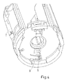
- Fig. 4 shows a bottom view of the actuator section 2 without the adapter 3 and the connection section 4.
- the first profiled surface 9 only comprises a limited number of teeth. All teeth of the first profiled surface 9 are in this embodiment arranged in the coupling section 8.
- Fig. 5 shows the adapter 3 in more detail.
- the second profiled surface 10 is arranged circumferentially on the top surface of the adapter 3.
- the adapter 3 here has the shape of a ring with a gap 12 to improve the flexibility of the adapter 3.
- the adapter 3 comprises two extensions 13 onto which the second profiled surface 10 also extends.
- the first profiled surface 9 as well as the second profiled surface 10 have a saw tooth-wave-like cross section in the direction around the rotational axis.
- Individual teeth of the first and second profiled surfaces 9, 10 each have one flank that is steeper than the other flank whereby the first profiled surface 9 may slide over the second profiled surface 10 when the coupling mechanism 6 is not engaged and the actuator section 2 is rotated in the second rotational direction. If the actuator section 2 is however rotated in the first rotational direction the adapter 3 and the actuator section 2 will be rotated in unison because the steeper flanks of the teeth engage one another.
- the actuator attachment 1 comprises a first connection geometry 14 for connecting the actuator attachment 1 to a valve.
- the first connection geometry 14 is disconnectable from the valve by engaging the coupling mechanism 6 while rotating the actuator section 2 in the second rotational direction.
- the first connection geometry 14 allows to disconnect the actuator section 2 and the adapter 3 from the connection section 4.
- the first connection geometry 14 may also be used to directly connect the actuator section 2 and the adapter 3 to the valve without an intermediate connection section 4 being involved.
- connection section 4 is thereby connectable to a valve, wherein the first connection geometry 14 is arranged in the adapter 3 whereby the adapter 3 and the actuator section 2 are connectable to the connection section 4.
- connection section 4 To unmount the actuator attachment 1 one may engage the coupling mechanism 6 while rotating the actuator section 2 and the adapter 3 in the second rotational direction relative to the valve until the actuator section 2 and the adapter 3 can be removed from the valve. In case no separate connection section 4 is used the complete actuator attachment 1 is thereby unmounted from the valve. In case a connection section 4 separate from the adapter 3 is part of the actuator attachment 1 the connection section 4 needs to be unmounted from the valve after the actuator section 2 and the adapter 3 have been removed from the valve by the above described method.
- the present invention therefore provides an actuator attachment 1 which allows to change the rotational position of an actuator attachment already installed on a valve. At the same time the actuator attachment allows a secure and firm connection to a valve while not requiring any tool or other complicated means for demounting the actuator attachment.
Landscapes
- Engineering & Computer Science (AREA)
- Physics & Mathematics (AREA)
- Thermal Sciences (AREA)
- Chemical & Material Sciences (AREA)
- Combustion & Propulsion (AREA)
- Mechanical Engineering (AREA)
- General Engineering & Computer Science (AREA)
- Mechanically-Actuated Valves (AREA)
Abstract
Description
- The invention relates to an actuator attachment for actuating a valve, in particular a radiator valve, comprising an actuator section as well as an adapter, wherein the adapter is unrotatably coupleable to the actuator section in a plurality of discreet relative rotational positions. The invention furthermore relates to a method of demounting such an actuator attachment from a valve.
- Actuator attachments are usually attached to an attachment geometry of a valve, for example a radiator valve, to control the flow of a fluid, for example through a radiator. Thereby the amount of heat dispensed by the radiator can be controlled.
- However, the attachment geometries of various valve manufacturers and valve types are different which requires the use of a matching connector. Furthermore, it is usually preferable if the actuator attachment can be brought into a certain rotational position such that for example a setting indicator or a display can be properly seen by a user.
- An actuator attachment of the above kind is for example known from
DE 10 104 897 A1 -
DE 10 2009 031 442 A1 shows an alternative solution dispensing with the use of profiled surfaces. The actuator section can be freely rotated on an adapter to change the rotational position of the actuator section. To demount the actuator section and the adapter from the valve or a connection section a tool is however required that needs to be inserted into aligned openings in the actuator section and the adapter. This solution is also not satisfactory, since there can be too much slack between the actuator section and the adapter to keep both parts relatively rotatable. Furthermore, the mounting and demounting is complicated. - The task of the present invention is therefore to provide an improved actuator attachment that can be rotationally adjusted and allows a simple and firm mounting and demounting.
- According to the present invention the above task is solved in an actuator attachment of the kind mentioned at the outset in that the adapter is unrotatably coupled to the actuator section when the actuator section is rotated in a first rotational direction and is rotatably coupled in an opposite, second rotational direction.
- Unrotatably coupled here means that the adapter and the actuator section can be rotated in unison in the first rotational direction, e.g. around a central axis of the actuator attachment. In this rotational direction the actuator section and the adapter can for example be screwed into a connection geometry of a valve or of an intermediate connection section. In the opposite, second rotational direction the actuator section can be rotated relative to the adapter and the valve, whereby one can adjust the rotational position of the actuator section relative to the adapter and the valve. Preferably, a rotation in the second rotational direction will then not lead to a dismounting of the actuator section and the adapter from the valve.
- Preferably, the actuator section comprises a coupling mechanism that is engagable to unrotatably couple the annular adapter to the actuator section temporarily in the second rotational direction as well. By engaging the coupling mechanism, e.g. by pressing and holding a button or the like, and then rotating the actuator section in the second rotational direction one may thus rotate the actuator section and the adapter in unison, for example to dismount the actuator attachment.
- It is preferred if the actuator section comprises a first profiled surface and the adapter comprises a second profiled surface, wherein the first and second profiled surfaces form a slip clutch. When the actuator section is rotated relative to the adapter in the first rotational direction the profiled surfaces engage one another and the actuator section and the adapter are rotatable in unison. However, if the actuator section is rotated in the second rotational direction the first profiled surface slips over the second profiled surface such that the actuator section rotates relative to the adapter. If however in the letter case the coupling mechanism is engaged the first profiled surface can for example be pressed against the second profiled surface whereby the friction is increased up to a point where rotating the actuator section will also rotate the adapter in the second rotational direction.
- It is preferred if at least one of the first and second profiled surfaces has a saw tooth-wave-like cross section in the direction around the rotational axis.
- It is furthermore preferred if the individual saw teeth in the first and second profiled surfaces each comprise one flank that is steeper than the other flank. This way one may ensure that the actuator section is rotationally coupled to the adapter in the first rotational direction but is rotatably coupled in the second rotational direction. However, if the coupling mechanism is engaged one may create sufficient friction such that the first and second profiled surfaces cannot slip over one another and the actuator section and the adapter are also unrotatably coupled in the second rotational direction.
- It is preferred if the coupling mechanism comprises an engagement surface of the actuator section that is manually engageable to temporarily unrotatably couple the adapter to the actuator section in the second rotational direction.
- It is preferred if the coupling mechanism comprises a coupling section that is flexible in a direction parallel to a rotational axis of the actuator section and the adapter. Preferably the coupling section is arranged in the actuator section. It is preferred if the first structured surface is limited to the coupling section in a circumferential direction around the rotational axis. This limits the friction between the actuator section and the adapter when the coupling mechanism is not engaged. In this case the coupling section may elastically deform whereby the actuator section can be rotated relative to the adapter in the second rotational direction.
- It is preferred if the coupling section is blockable from a displacement parallel to the rotational axis by engaging the coupling mechanism. By engaging the coupling mechanism one may then lock the actuator section and the adapter whereby one may rotate the actuator section and the adapter in unison in the second rotational direction for example to unmount the actuator attachment from the valve.
- It is preferred if the actuator attachment comprises a first connection geometry for connecting the actuator attachment to a valve, wherein the first connection geometry is disconnectable from the valve by engaging the coupling mechanism while rotating the actuator section in the second rotational direction.
- It is preferred if the actuator attachment comprises a connection section that is connectable to a valve, wherein the adapter is arranged between the connection section and the actuator section. In this case the connection section may be mounted to the valve first and afterwards the adapter as well as the actuator section may be mounted to the connection section.
- It is preferred if the actuator attachment comprises a second connection geometry, that is arranged in the connection section whereby the connection section is connectable to a valve, wherein the first connection geometry is arranged in the adapter whereby the adapter and the actuator section are connectable to the connection section. The first connection geometry then connects the adapter to the connection section and the second connection geometry allows to connect the connection section and thereby the whole actuator attachment to the valve.
- The above task is furthermore solved by a method for demounting an actuator attachment according to any of
claims 2 to 11 from a valve, comprising the steps: - Engaging the coupling mechanism,
- Rotating the actuator section and the adapter in the second rotational direction relative to the valve until the actuator section and the adapter can be removed from the valve.
- It is preferred if the actuator section and the adapter are first demounted from the connection section and afterwards the connection section is demounted from the valve. In this case by engaging the coupling mechanism the adapter and the actuator section can be rotated in the second rotational direction and demounted from the connection section and the valve. Afterwards the connection section is easier to access and can be demounted from the valve.
- A preferred embodiment of the invention is now explained with reference to the figures, wherein:
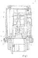
- Fig. 1
- shows a cut view of an actuator attachment according to the invention,
- Fig. 2
- shows the actuator attachment according to
fig.1 with an engaged coupling mechanism, - Fig. 3
- shows the actuator attachment according to
fig. 1 and2 with a cut through the coupling mechanism, - Fig. 4
- shows a bottom view of an actuator section according to the invention,
- Fig. 5
- shows an adapter of an actuator attachment according to the invention,
- Fig. 6
- shows an external view of an actuator section of an actuator attachment according to the invention.
-
Fig. 1 to 6 show the same embodiment of anactuator attachment 1 comprising anactuator section 2 as well as anadapter 3. Theactuator attachment 1 furthermore comprises a connection section 4 through which theactuator attachment 1 may be connected to a valve. Alternatively, the actuator attachment may be connected to a valve directly through theadapter 3. It is also possible for the connection section 4 to be an integral part of theadapter 3. - In the given embodiment the
adapter 3 is arranged between the connection section 4 and theactuator section 2. Theactuator section 2 comprises anactuating drive 5 for actuating a pin or a stem of a valve (not shown) onto which theactuator attachment 1 is mounted. - The
actuator section 2 can be rotated in unison with theadapter 3 in a first rotational direction around a central axis of theactuator attachment 1. In this first rotational direction theactuator section 2 and theadapter 3 are therefore unrotatably coupleable in a plurality of discreet relative rotational positions. On the other hand theactuator section 2 is rotatably coupled to theadapter 3 in the opposite, second rotational direction around the central axis. For example theactuator section 2 and theadapter 3 can be unrotatably coupled when the actuator section is rotated in a clockwise direction and theactuator section 2 can be rotatably coupled to theadapter 3 when theactuator section 2 is rotated in an counter-clockwise direction (or vice versa). Rotating theactuator section 2 in the first rotational direction may then be used to connect theactuator section 2 and theadapter 3 to the valve or in case a connection section 4 is used to the connection section 4. Once theactuator attachment 1 is fully attached to the valve one may then rotate theactuator section 2 in the second rotational direction relative to the valve and theadapter 3 whereby the relative rotational position can be adjusted. This for example allows to choose a rotational position of theactuator section 2 in which a display and/or an interface arranged in theactuator section 2 is optimally visible to a user. - The
actuator attachment 1 may be directly connectable to a valve via theadapter 3 or theactuator attachment 1 may be connectable via the connection section 4 if present as a separate part from theadapter 3. - In case the
actuator attachment 1 needs to be demounted, for example to replace a battery, it may be necessary to unrotatably couple theactuator section 2 to theadapter 3 in the second rotational direction also. To this end theactuator attachment 1 comprises acoupling mechanism 6. Thecoupling mechanism 6 can be engaged to unrotatably couple theadapter 3 to theactuator section 2 temporarily while theactuator section 2 is rotated in the second rotational direction to unmount theactuator attachment 1. Thecoupling mechanism 6 comprises anengagement surface 7 located on an outer surface of theactuator section 2. By engaging the engagement surface 7 a section of the actuator section is elastically deformed inwards to block acoupling section 8 of theactuator section 2. Thecoupling section 8 is located in the direct vicinity of theadapter 3. Thecoupling section 8 is flexible in a direction parallel to the rotational axis of theactuator section 2 and theadapter 3, in this case the vertical direction as shown in the orientation offig. 1 and2 . -
Fig. 3 shows a cut view through thecoupling mechanism 6 such that thecoupling section 8 becomes visible. Theactuator section 2 comprises a first profiledsurface 9 and theadapter 3 comprises a second profiledsurface 10. Thecoupling section 8 furthermore comprises a blockingprotrusion 11 at which thecoupling section 8 is engaged when theengagement surface 7 is pressed inwardly as shown infig. 2 .
When thecoupling mechanism 6 is however not engaged thecoupling section 8 can elastically deform upwards such that the first profiledsurface 9 can slip over the second profiledsurface 10 when theactuator section 2 is rotated in the second rotational direction, in the given embodiment in the counter clockwise direction. The first profiledsurface 9 and the second profiledsurface 10 thus form a slip clutch between theactuator section 2 and theadapter 3. -
Fig. 4 shows a bottom view of theactuator section 2 without theadapter 3 and the connection section 4. As one can see the first profiledsurface 9 only comprises a limited number of teeth. All teeth of the first profiledsurface 9 are in this embodiment arranged in thecoupling section 8. -
Fig. 5 shows theadapter 3 in more detail. As one can see the second profiledsurface 10 is arranged circumferentially on the top surface of theadapter 3. Theadapter 3 here has the shape of a ring with agap 12 to improve the flexibility of theadapter 3. To ensure that thecoupling mechanism 6 also works if thecoupling section 8 is located above thegap 12 theadapter 3 comprises twoextensions 13 onto which the second profiledsurface 10 also extends. - The first profiled
surface 9 as well as the second profiledsurface 10 have a saw tooth-wave-like cross section in the direction around the rotational axis. Individual teeth of the first and second profiledsurfaces surface 9 may slide over the second profiledsurface 10 when thecoupling mechanism 6 is not engaged and theactuator section 2 is rotated in the second rotational direction. If theactuator section 2 is however rotated in the first rotational direction theadapter 3 and theactuator section 2 will be rotated in unison because the steeper flanks of the teeth engage one another. - In the given embodiment the
actuator attachment 1 comprises a first connection geometry 14 for connecting theactuator attachment 1 to a valve. - The first connection geometry 14 is disconnectable from the valve by engaging the
coupling mechanism 6 while rotating theactuator section 2 in the second rotational direction. In the given embodiment the first connection geometry 14 allows to disconnect theactuator section 2 and theadapter 3 from the connection section 4. Alternatively, in case no separate connection section 4 is used the first connection geometry 14 may also be used to directly connect theactuator section 2 and theadapter 3 to the valve without an intermediate connection section 4 being involved. - In the given embodiment a
second connection geometry 15 is arranged in the connection section 4. The connection section 4 is thereby connectable to a valve, wherein the first connection geometry 14 is arranged in theadapter 3 whereby theadapter 3 and theactuator section 2 are connectable to the connection section 4. - To unmount the
actuator attachment 1 one may engage thecoupling mechanism 6 while rotating theactuator section 2 and theadapter 3 in the second rotational direction relative to the valve until theactuator section 2 and theadapter 3 can be removed from the valve. In case no separate connection section 4 is used thecomplete actuator attachment 1 is thereby unmounted from the valve. In case a connection section 4 separate from theadapter 3 is part of theactuator attachment 1 the connection section 4 needs to be unmounted from the valve after theactuator section 2 and theadapter 3 have been removed from the valve by the above described method. - The present invention therefore provides an
actuator attachment 1 which allows to change the rotational position of an actuator attachment already installed on a valve. At the same time the actuator attachment allows a secure and firm connection to a valve while not requiring any tool or other complicated means for demounting the actuator attachment.
Claims (13)
- Actuator attachment (1) for actuating a valve, in particular a radiator valve, comprising an actuator section (2) as well as an adapter (3), wherein the adapter (3) is unrotatably coupleable to the actuator section (2) in a plurality of discreet relative rotational positions, characterized in that the adapter (3) is unrotatably coupled to the actuator section (2) when the actuator section (2) is rotated in a first rotational direction and is rotatably coupled to the adapter (3) in an opposite, second rotational direction.
- The valve attachment (1) according to claim 1, characterized in that the actuator attachment (1) comprises a coupling mechanism (6) that is engagable to unrotatably couple the adapter (3) to the actuator section (2) temporarily in the second rotational direction as well.
- Actuator attachment (1) according to claim 1 or 2, characterized in that the actuator section (2) comprises a first profiled surface (9) and the adapter (3) comprises a second profiled surface (10), wherein the first and second profiled surfaces (9, 10) form a slip clutch.
- The actuator attachment (1) according to claim 3, characterized in that at least one of the first and second profiled surfaces (9, 10) has a saw tooth-wave-like cross section in the direction around the rotational axis.
- The actuator attachment (1) according to claim 4, characterized in that the individual saw tooth in the profiled surfaces (9, 10) each comprise one flank that is steeper than the other flank.
- The actuator attachment (1) according to any of claims 2 to 5, characterized in that the coupling mechanism (6) comprises an engagement surface (7) of the actuator section (2) that is manually engageable to temporarily unrotatably couple the adapter (3) to the actuator section (2) in the second rotational direction.
- The actuator attachment (1) according to any of claims 2 to 6, characterized in that the coupling mechanism (6) comprises a coupling section (8) that is flexible in a direction parallel to the rotational axis of the actuator section (2) and the adapter (3).
- The actuator attachment (1) according to claim 7, characterized in that the coupling section (8) is blockable from a displacement parallel to the rotational axis by engaging the coupling mechanism (6).
- The actuator attachment (1) according to any of claims 2 to 8, characterized in that the actuator attachment (1) comprises a first connection geometry (14) for connecting the actuator attachment (1) to a valve, wherein the first connection geometry (14) is disconnectable from a valve by engaging the coupling mechanism (6) while rotating the actuator section (2) in the second rotational direction.
- The actuator attachment (1) comprising a connection section (4) that is connectable to a valve, wherein the adapter (3) is arranged between the connection section (4) and the actuator section (2).
- The actuator attachment according to claim 10, characterized in that the actuator attachment (1) comprises a second connection geometry (15) that is arranged in the connection section (4), whereby the connection section (4) is connectable to a valve, wherein the first connection geometry (14) is arranged in the adapter (3) whereby the adapter (3) and the actuator section (2) are connectable to the connection section (4).
- Method for demounting an actuator attachment (1) according to any of claims 2 to 11 from a valve, comprising the steps:- Engaging the coupling mechanism (6),- Rotating the actuator section (2) and the adapter (3) in the second rotational direction relative to the valve until the actuator section (2) and the adapter (3) can be removed from the valve.
- Method according to claim 12, wherein the actuator section (2) and the adapter (3) are first demounted from the connection section (4) and afterwards the connection section (4) is demounted from the valve.
Priority Applications (3)
| Application Number | Priority Date | Filing Date | Title |
|---|---|---|---|
| DK16173963.6T DK3255351T3 (en) | 2016-06-10 | 2016-06-10 | Actuator device and method of removing an actuator device |
| EP16173963.6A EP3255351B1 (en) | 2016-06-10 | 2016-06-10 | Actuator attachment and method for demounting an actuator attachment |
| PL16173963T PL3255351T3 (en) | 2016-06-10 | 2016-06-10 | Actuator attachment and method for demounting an actuator attachment |
Applications Claiming Priority (1)
| Application Number | Priority Date | Filing Date | Title |
|---|---|---|---|
| EP16173963.6A EP3255351B1 (en) | 2016-06-10 | 2016-06-10 | Actuator attachment and method for demounting an actuator attachment |
Publications (2)
| Publication Number | Publication Date |
|---|---|
| EP3255351A1 true EP3255351A1 (en) | 2017-12-13 |
| EP3255351B1 EP3255351B1 (en) | 2018-08-01 |
Family
ID=56411376
Family Applications (1)
| Application Number | Title | Priority Date | Filing Date |
|---|---|---|---|
| EP16173963.6A Active EP3255351B1 (en) | 2016-06-10 | 2016-06-10 | Actuator attachment and method for demounting an actuator attachment |
Country Status (3)
| Country | Link |
|---|---|
| EP (1) | EP3255351B1 (en) |
| DK (1) | DK3255351T3 (en) |
| PL (1) | PL3255351T3 (en) |
Citations (4)
| Publication number | Priority date | Publication date | Assignee | Title |
|---|---|---|---|---|
| GB1560040A (en) * | 1976-11-25 | 1980-01-30 | Braukmann H W | Concealed thermostatic control valve |
| US4632437A (en) * | 1985-04-03 | 1986-12-30 | Robson Anthony R | Pipe coupling |
| DE4038141C1 (en) * | 1990-11-30 | 1992-05-27 | Danfoss A/S, Nordborg, Dk | |
| US6471255B1 (en) * | 2000-03-13 | 2002-10-29 | Richard L. Ulrich | Anti-rotation arrangement for a detection device assembly |
-
2016
- 2016-06-10 PL PL16173963T patent/PL3255351T3/en unknown
- 2016-06-10 EP EP16173963.6A patent/EP3255351B1/en active Active
- 2016-06-10 DK DK16173963.6T patent/DK3255351T3/en active
Patent Citations (4)
| Publication number | Priority date | Publication date | Assignee | Title |
|---|---|---|---|---|
| GB1560040A (en) * | 1976-11-25 | 1980-01-30 | Braukmann H W | Concealed thermostatic control valve |
| US4632437A (en) * | 1985-04-03 | 1986-12-30 | Robson Anthony R | Pipe coupling |
| DE4038141C1 (en) * | 1990-11-30 | 1992-05-27 | Danfoss A/S, Nordborg, Dk | |
| US6471255B1 (en) * | 2000-03-13 | 2002-10-29 | Richard L. Ulrich | Anti-rotation arrangement for a detection device assembly |
Also Published As
| Publication number | Publication date |
|---|---|
| PL3255351T3 (en) | 2019-02-28 |
| EP3255351B1 (en) | 2018-08-01 |
| DK3255351T3 (en) | 2018-11-19 |
Similar Documents
| Publication | Publication Date | Title |
|---|---|---|
| AU2023200835B2 (en) | Releasable Fastener | |
| EP2690326B1 (en) | Ball valve | |
| WO2009142706A2 (en) | Valve control assembly | |
| CN101639135B (en) | Fluid conveyance and/or distribution device with ring nut coupling | |
| US20110186142A1 (en) | Universal water control trim | |
| AU2020203576A1 (en) | Releasable Fastener | |
| EP3255351B1 (en) | Actuator attachment and method for demounting an actuator attachment | |
| CN209125713U (en) | Installation and removal device for grinding wheel | |
| US11346425B2 (en) | Anti-rotational locking device | |
| EP2453153A1 (en) | Fluid conveyance and / or distributing device with ring nut coupling | |
| EP1359489A2 (en) | Device for selecting the operating mode of control heads in particular for thermostatic valves | |
| EP2952755B1 (en) | Torque limiting connecting component | |
| EP3162970A1 (en) | Covering rosette for a concealed sanitary fitting | |
| GB2446406A (en) | A device for indicating rotational position of a nut or bolt | |
| US8672599B2 (en) | Securing element for securing against unauthorized unscrewing | |
| CN104972296B (en) | For making the method and positioner that the rotation position of at least two components aligns | |
| WO2018171855A1 (en) | Adjustment unit for the range of a headlight for a vehicle | |
| EP3156706B1 (en) | Valve attachment and valve arrangement | |
| GB2607256A (en) | Plumbing fitting | |
| CN214063967U (en) | Prevent maloperation valve fixing device | |
| EP3193049B1 (en) | Valve | |
| US20200224708A1 (en) | Nut-locking device and associated assembly unit | |
| US11157033B2 (en) | Calibration knob | |
| US20230383861A1 (en) | Lockable latch | |
| US20200240457A1 (en) | Nut locking device and assembly for mounting same |
Legal Events
| Date | Code | Title | Description |
|---|---|---|---|
| PUAI | Public reference made under article 153(3) epc to a published international application that has entered the european phase |
Free format text: ORIGINAL CODE: 0009012 |
|
| STAA | Information on the status of an ep patent application or granted ep patent |
Free format text: STATUS: REQUEST FOR EXAMINATION WAS MADE |
|
| 17P | Request for examination filed |
Effective date: 20161227 |
|
| AK | Designated contracting states |
Kind code of ref document: A1 Designated state(s): AL AT BE BG CH CY CZ DE DK EE ES FI FR GB GR HR HU IE IS IT LI LT LU LV MC MK MT NL NO PL PT RO RS SE SI SK SM TR |
|
| AX | Request for extension of the european patent |
Extension state: BA ME |
|
| GRAP | Despatch of communication of intention to grant a patent |
Free format text: ORIGINAL CODE: EPIDOSNIGR1 |
|
| STAA | Information on the status of an ep patent application or granted ep patent |
Free format text: STATUS: GRANT OF PATENT IS INTENDED |
|
| INTG | Intention to grant announced |
Effective date: 20180220 |
|
| GRAS | Grant fee paid |
Free format text: ORIGINAL CODE: EPIDOSNIGR3 |
|
| GRAA | (expected) grant |
Free format text: ORIGINAL CODE: 0009210 |
|
| STAA | Information on the status of an ep patent application or granted ep patent |
Free format text: STATUS: THE PATENT HAS BEEN GRANTED |
|
| AK | Designated contracting states |
Kind code of ref document: B1 Designated state(s): AL AT BE BG CH CY CZ DE DK EE ES FI FR GB GR HR HU IE IS IT LI LT LU LV MC MK MT NL NO PL PT RO RS SE SI SK SM TR |
|
| REG | Reference to a national code |
Ref country code: GB Ref legal event code: FG4D |
|
| REG | Reference to a national code |
Ref country code: CH Ref legal event code: EP Ref country code: AT Ref legal event code: REF Ref document number: 1024752 Country of ref document: AT Kind code of ref document: T Effective date: 20180815 |
|
| REG | Reference to a national code |
Ref country code: IE Ref legal event code: FG4D |
|
| REG | Reference to a national code |
Ref country code: DE Ref legal event code: R096 Ref document number: 602016004433 Country of ref document: DE |
|
| REG | Reference to a national code |
Ref country code: NL Ref legal event code: FP |
|
| REG | Reference to a national code |
Ref country code: DK Ref legal event code: T3 Effective date: 20181112 |
|
| REG | Reference to a national code |
Ref country code: LT Ref legal event code: MG4D |
|
| REG | Reference to a national code |
Ref country code: AT Ref legal event code: MK05 Ref document number: 1024752 Country of ref document: AT Kind code of ref document: T Effective date: 20180801 |
|
| PG25 | Lapsed in a contracting state [announced via postgrant information from national office to epo] |
Ref country code: SE Free format text: LAPSE BECAUSE OF FAILURE TO SUBMIT A TRANSLATION OF THE DESCRIPTION OR TO PAY THE FEE WITHIN THE PRESCRIBED TIME-LIMIT Effective date: 20180801 Ref country code: AT Free format text: LAPSE BECAUSE OF FAILURE TO SUBMIT A TRANSLATION OF THE DESCRIPTION OR TO PAY THE FEE WITHIN THE PRESCRIBED TIME-LIMIT Effective date: 20180801 Ref country code: IS Free format text: LAPSE BECAUSE OF FAILURE TO SUBMIT A TRANSLATION OF THE DESCRIPTION OR TO PAY THE FEE WITHIN THE PRESCRIBED TIME-LIMIT Effective date: 20181201 Ref country code: NO Free format text: LAPSE BECAUSE OF FAILURE TO SUBMIT A TRANSLATION OF THE DESCRIPTION OR TO PAY THE FEE WITHIN THE PRESCRIBED TIME-LIMIT Effective date: 20181101 Ref country code: BG Free format text: LAPSE BECAUSE OF FAILURE TO SUBMIT A TRANSLATION OF THE DESCRIPTION OR TO PAY THE FEE WITHIN THE PRESCRIBED TIME-LIMIT Effective date: 20181101 Ref country code: GR Free format text: LAPSE BECAUSE OF FAILURE TO SUBMIT A TRANSLATION OF THE DESCRIPTION OR TO PAY THE FEE WITHIN THE PRESCRIBED TIME-LIMIT Effective date: 20181102 Ref country code: RS Free format text: LAPSE BECAUSE OF FAILURE TO SUBMIT A TRANSLATION OF THE DESCRIPTION OR TO PAY THE FEE WITHIN THE PRESCRIBED TIME-LIMIT Effective date: 20180801 Ref country code: LT Free format text: LAPSE BECAUSE OF FAILURE TO SUBMIT A TRANSLATION OF THE DESCRIPTION OR TO PAY THE FEE WITHIN THE PRESCRIBED TIME-LIMIT Effective date: 20180801 Ref country code: FI Free format text: LAPSE BECAUSE OF FAILURE TO SUBMIT A TRANSLATION OF THE DESCRIPTION OR TO PAY THE FEE WITHIN THE PRESCRIBED TIME-LIMIT Effective date: 20180801 |
|
| PG25 | Lapsed in a contracting state [announced via postgrant information from national office to epo] |
Ref country code: AL Free format text: LAPSE BECAUSE OF FAILURE TO SUBMIT A TRANSLATION OF THE DESCRIPTION OR TO PAY THE FEE WITHIN THE PRESCRIBED TIME-LIMIT Effective date: 20180801 Ref country code: LV Free format text: LAPSE BECAUSE OF FAILURE TO SUBMIT A TRANSLATION OF THE DESCRIPTION OR TO PAY THE FEE WITHIN THE PRESCRIBED TIME-LIMIT Effective date: 20180801 Ref country code: HR Free format text: LAPSE BECAUSE OF FAILURE TO SUBMIT A TRANSLATION OF THE DESCRIPTION OR TO PAY THE FEE WITHIN THE PRESCRIBED TIME-LIMIT Effective date: 20180801 |
|
| PG25 | Lapsed in a contracting state [announced via postgrant information from national office to epo] |
Ref country code: IT Free format text: LAPSE BECAUSE OF FAILURE TO SUBMIT A TRANSLATION OF THE DESCRIPTION OR TO PAY THE FEE WITHIN THE PRESCRIBED TIME-LIMIT Effective date: 20180801 Ref country code: ES Free format text: LAPSE BECAUSE OF FAILURE TO SUBMIT A TRANSLATION OF THE DESCRIPTION OR TO PAY THE FEE WITHIN THE PRESCRIBED TIME-LIMIT Effective date: 20180801 Ref country code: CZ Free format text: LAPSE BECAUSE OF FAILURE TO SUBMIT A TRANSLATION OF THE DESCRIPTION OR TO PAY THE FEE WITHIN THE PRESCRIBED TIME-LIMIT Effective date: 20180801 Ref country code: EE Free format text: LAPSE BECAUSE OF FAILURE TO SUBMIT A TRANSLATION OF THE DESCRIPTION OR TO PAY THE FEE WITHIN THE PRESCRIBED TIME-LIMIT Effective date: 20180801 Ref country code: RO Free format text: LAPSE BECAUSE OF FAILURE TO SUBMIT A TRANSLATION OF THE DESCRIPTION OR TO PAY THE FEE WITHIN THE PRESCRIBED TIME-LIMIT Effective date: 20180801 |
|
| REG | Reference to a national code |
Ref country code: DE Ref legal event code: R097 Ref document number: 602016004433 Country of ref document: DE |
|
| PG25 | Lapsed in a contracting state [announced via postgrant information from national office to epo] |
Ref country code: SM Free format text: LAPSE BECAUSE OF FAILURE TO SUBMIT A TRANSLATION OF THE DESCRIPTION OR TO PAY THE FEE WITHIN THE PRESCRIBED TIME-LIMIT Effective date: 20180801 Ref country code: SK Free format text: LAPSE BECAUSE OF FAILURE TO SUBMIT A TRANSLATION OF THE DESCRIPTION OR TO PAY THE FEE WITHIN THE PRESCRIBED TIME-LIMIT Effective date: 20180801 |
|
| PLBE | No opposition filed within time limit |
Free format text: ORIGINAL CODE: 0009261 |
|
| STAA | Information on the status of an ep patent application or granted ep patent |
Free format text: STATUS: NO OPPOSITION FILED WITHIN TIME LIMIT |
|
| 26N | No opposition filed |
Effective date: 20190503 |
|
| PG25 | Lapsed in a contracting state [announced via postgrant information from national office to epo] |
Ref country code: SI Free format text: LAPSE BECAUSE OF FAILURE TO SUBMIT A TRANSLATION OF THE DESCRIPTION OR TO PAY THE FEE WITHIN THE PRESCRIBED TIME-LIMIT Effective date: 20180801 |
|
| PG25 | Lapsed in a contracting state [announced via postgrant information from national office to epo] |
Ref country code: MC Free format text: LAPSE BECAUSE OF FAILURE TO SUBMIT A TRANSLATION OF THE DESCRIPTION OR TO PAY THE FEE WITHIN THE PRESCRIBED TIME-LIMIT Effective date: 20180801 |
|
| REG | Reference to a national code |
Ref country code: CH Ref legal event code: PL |
|
| REG | Reference to a national code |
Ref country code: BE Ref legal event code: MM Effective date: 20190630 |
|
| PG25 | Lapsed in a contracting state [announced via postgrant information from national office to epo] |
Ref country code: TR Free format text: LAPSE BECAUSE OF FAILURE TO SUBMIT A TRANSLATION OF THE DESCRIPTION OR TO PAY THE FEE WITHIN THE PRESCRIBED TIME-LIMIT Effective date: 20180801 |
|
| PG25 | Lapsed in a contracting state [announced via postgrant information from national office to epo] |
Ref country code: IE Free format text: LAPSE BECAUSE OF NON-PAYMENT OF DUE FEES Effective date: 20190610 |
|
| PG25 | Lapsed in a contracting state [announced via postgrant information from national office to epo] |
Ref country code: LI Free format text: LAPSE BECAUSE OF NON-PAYMENT OF DUE FEES Effective date: 20190630 Ref country code: LU Free format text: LAPSE BECAUSE OF NON-PAYMENT OF DUE FEES Effective date: 20190610 Ref country code: CH Free format text: LAPSE BECAUSE OF NON-PAYMENT OF DUE FEES Effective date: 20190630 Ref country code: BE Free format text: LAPSE BECAUSE OF NON-PAYMENT OF DUE FEES Effective date: 20190630 |
|
| PG25 | Lapsed in a contracting state [announced via postgrant information from national office to epo] |
Ref country code: PT Free format text: LAPSE BECAUSE OF FAILURE TO SUBMIT A TRANSLATION OF THE DESCRIPTION OR TO PAY THE FEE WITHIN THE PRESCRIBED TIME-LIMIT Effective date: 20181201 |
|
| PG25 | Lapsed in a contracting state [announced via postgrant information from national office to epo] |
Ref country code: CY Free format text: LAPSE BECAUSE OF FAILURE TO SUBMIT A TRANSLATION OF THE DESCRIPTION OR TO PAY THE FEE WITHIN THE PRESCRIBED TIME-LIMIT Effective date: 20180801 |
|
| PG25 | Lapsed in a contracting state [announced via postgrant information from national office to epo] |
Ref country code: MT Free format text: LAPSE BECAUSE OF FAILURE TO SUBMIT A TRANSLATION OF THE DESCRIPTION OR TO PAY THE FEE WITHIN THE PRESCRIBED TIME-LIMIT Effective date: 20180801 Ref country code: HU Free format text: LAPSE BECAUSE OF FAILURE TO SUBMIT A TRANSLATION OF THE DESCRIPTION OR TO PAY THE FEE WITHIN THE PRESCRIBED TIME-LIMIT; INVALID AB INITIO Effective date: 20160610 |
|
| PG25 | Lapsed in a contracting state [announced via postgrant information from national office to epo] |
Ref country code: MK Free format text: LAPSE BECAUSE OF FAILURE TO SUBMIT A TRANSLATION OF THE DESCRIPTION OR TO PAY THE FEE WITHIN THE PRESCRIBED TIME-LIMIT Effective date: 20180801 |
|
| P01 | Opt-out of the competence of the unified patent court (upc) registered |
Effective date: 20230617 |
|
| PGFP | Annual fee paid to national office [announced via postgrant information from national office to epo] |
Ref country code: NL Payment date: 20260514 Year of fee payment: 11 |
|
| PGFP | Annual fee paid to national office [announced via postgrant information from national office to epo] |
Ref country code: GB Payment date: 20260511 Year of fee payment: 11 Ref country code: DK Payment date: 20260611 Year of fee payment: 11 Ref country code: PL Payment date: 20260512 Year of fee payment: 11 |
|
| PGFP | Annual fee paid to national office [announced via postgrant information from national office to epo] |
Ref country code: DE Payment date: 20260506 Year of fee payment: 11 |
|
| PGFP | Annual fee paid to national office [announced via postgrant information from national office to epo] |
Ref country code: FR Payment date: 20260521 Year of fee payment: 11 |