EP3255202B1 - Household appliance comprising a heat pump - Google Patents
Household appliance comprising a heat pump Download PDFInfo
- Publication number
- EP3255202B1 EP3255202B1 EP16382263.8A EP16382263A EP3255202B1 EP 3255202 B1 EP3255202 B1 EP 3255202B1 EP 16382263 A EP16382263 A EP 16382263A EP 3255202 B1 EP3255202 B1 EP 3255202B1
- Authority
- EP
- European Patent Office
- Prior art keywords
- port
- refrigerant
- condenser
- evaporator
- household appliance
- Prior art date
- Legal status (The legal status is an assumption and is not a legal conclusion. Google has not performed a legal analysis and makes no representation as to the accuracy of the status listed.)
- Active
Links
Images



Classifications
-
- D—TEXTILES; PAPER
- D06—TREATMENT OF TEXTILES OR THE LIKE; LAUNDERING; FLEXIBLE MATERIALS NOT OTHERWISE PROVIDED FOR
- D06F—LAUNDERING, DRYING, IRONING, PRESSING OR FOLDING TEXTILE ARTICLES
- D06F58/00—Domestic laundry dryers
- D06F58/20—General details of domestic laundry dryers
- D06F58/206—Heat pump arrangements
-
- A—HUMAN NECESSITIES
- A47—FURNITURE; DOMESTIC ARTICLES OR APPLIANCES; COFFEE MILLS; SPICE MILLS; SUCTION CLEANERS IN GENERAL
- A47L—DOMESTIC WASHING OR CLEANING; SUCTION CLEANERS IN GENERAL
- A47L15/00—Washing or rinsing machines for crockery or tableware
- A47L15/42—Details
- A47L15/4291—Recovery arrangements, e.g. for the recovery of energy or water
-
- F—MECHANICAL ENGINEERING; LIGHTING; HEATING; WEAPONS; BLASTING
- F25—REFRIGERATION OR COOLING; COMBINED HEATING AND REFRIGERATION SYSTEMS; HEAT PUMP SYSTEMS; MANUFACTURE OR STORAGE OF ICE; LIQUEFACTION SOLIDIFICATION OF GASES
- F25B—REFRIGERATION MACHINES, PLANTS OR SYSTEMS; COMBINED HEATING AND REFRIGERATION SYSTEMS; HEAT PUMP SYSTEMS
- F25B30/00—Heat pumps
- F25B30/02—Heat pumps of the compression type
-
- D—TEXTILES; PAPER
- D06—TREATMENT OF TEXTILES OR THE LIKE; LAUNDERING; FLEXIBLE MATERIALS NOT OTHERWISE PROVIDED FOR
- D06F—LAUNDERING, DRYING, IRONING, PRESSING OR FOLDING TEXTILE ARTICLES
- D06F2103/00—Parameters monitored or detected for the control of domestic laundry washing machines, washer-dryers or laundry dryers
-
- D—TEXTILES; PAPER
- D06—TREATMENT OF TEXTILES OR THE LIKE; LAUNDERING; FLEXIBLE MATERIALS NOT OTHERWISE PROVIDED FOR
- D06F—LAUNDERING, DRYING, IRONING, PRESSING OR FOLDING TEXTILE ARTICLES
- D06F2103/00—Parameters monitored or detected for the control of domestic laundry washing machines, washer-dryers or laundry dryers
- D06F2103/28—Air properties
- D06F2103/30—Pressure
-
- D—TEXTILES; PAPER
- D06—TREATMENT OF TEXTILES OR THE LIKE; LAUNDERING; FLEXIBLE MATERIALS NOT OTHERWISE PROVIDED FOR
- D06F—LAUNDERING, DRYING, IRONING, PRESSING OR FOLDING TEXTILE ARTICLES
- D06F2103/00—Parameters monitored or detected for the control of domestic laundry washing machines, washer-dryers or laundry dryers
- D06F2103/28—Air properties
- D06F2103/32—Temperature
-
- D—TEXTILES; PAPER
- D06—TREATMENT OF TEXTILES OR THE LIKE; LAUNDERING; FLEXIBLE MATERIALS NOT OTHERWISE PROVIDED FOR
- D06F—LAUNDERING, DRYING, IRONING, PRESSING OR FOLDING TEXTILE ARTICLES
- D06F2103/00—Parameters monitored or detected for the control of domestic laundry washing machines, washer-dryers or laundry dryers
- D06F2103/50—Parameters monitored or detected for the control of domestic laundry washing machines, washer-dryers or laundry dryers related to heat pumps, e.g. pressure or flow rate
-
- D—TEXTILES; PAPER
- D06—TREATMENT OF TEXTILES OR THE LIKE; LAUNDERING; FLEXIBLE MATERIALS NOT OTHERWISE PROVIDED FOR
- D06F—LAUNDERING, DRYING, IRONING, PRESSING OR FOLDING TEXTILE ARTICLES
- D06F2105/00—Systems or parameters controlled or affected by the control systems of washing machines, washer-dryers or laundry dryers
- D06F2105/26—Heat pumps
-
- D—TEXTILES; PAPER
- D06—TREATMENT OF TEXTILES OR THE LIKE; LAUNDERING; FLEXIBLE MATERIALS NOT OTHERWISE PROVIDED FOR
- D06F—LAUNDERING, DRYING, IRONING, PRESSING OR FOLDING TEXTILE ARTICLES
- D06F2105/00—Systems or parameters controlled or affected by the control systems of washing machines, washer-dryers or laundry dryers
- D06F2105/36—Condensing arrangements, e.g. control of water injection therefor
-
- D—TEXTILES; PAPER
- D06—TREATMENT OF TEXTILES OR THE LIKE; LAUNDERING; FLEXIBLE MATERIALS NOT OTHERWISE PROVIDED FOR
- D06F—LAUNDERING, DRYING, IRONING, PRESSING OR FOLDING TEXTILE ARTICLES
- D06F25/00—Washing machines with receptacles, e.g. perforated, having a rotary movement, e.g. oscillatory movement, the receptacle serving both for washing and for centrifugally separating water from the laundry and having further drying means, e.g. using hot air
-
- D—TEXTILES; PAPER
- D06—TREATMENT OF TEXTILES OR THE LIKE; LAUNDERING; FLEXIBLE MATERIALS NOT OTHERWISE PROVIDED FOR
- D06F—LAUNDERING, DRYING, IRONING, PRESSING OR FOLDING TEXTILE ARTICLES
- D06F34/00—Details of control systems for washing machines, washer-dryers or laundry dryers
- D06F34/08—Control circuits or arrangements thereof
-
- D—TEXTILES; PAPER
- D06—TREATMENT OF TEXTILES OR THE LIKE; LAUNDERING; FLEXIBLE MATERIALS NOT OTHERWISE PROVIDED FOR
- D06F—LAUNDERING, DRYING, IRONING, PRESSING OR FOLDING TEXTILE ARTICLES
- D06F58/00—Domestic laundry dryers
- D06F58/20—General details of domestic laundry dryers
-
- D—TEXTILES; PAPER
- D06—TREATMENT OF TEXTILES OR THE LIKE; LAUNDERING; FLEXIBLE MATERIALS NOT OTHERWISE PROVIDED FOR
- D06F—LAUNDERING, DRYING, IRONING, PRESSING OR FOLDING TEXTILE ARTICLES
- D06F58/00—Domestic laundry dryers
- D06F58/32—Control of operations performed in domestic laundry dryers
- D06F58/34—Control of operations performed in domestic laundry dryers characterised by the purpose or target of the control
-
- Y—GENERAL TAGGING OF NEW TECHNOLOGICAL DEVELOPMENTS; GENERAL TAGGING OF CROSS-SECTIONAL TECHNOLOGIES SPANNING OVER SEVERAL SECTIONS OF THE IPC; TECHNICAL SUBJECTS COVERED BY FORMER USPC CROSS-REFERENCE ART COLLECTIONS [XRACs] AND DIGESTS
- Y02—TECHNOLOGIES OR APPLICATIONS FOR MITIGATION OR ADAPTATION AGAINST CLIMATE CHANGE
- Y02B—CLIMATE CHANGE MITIGATION TECHNOLOGIES RELATED TO BUILDINGS, e.g. HOUSING, HOUSE APPLIANCES OR RELATED END-USER APPLICATIONS
- Y02B30/00—Energy efficient heating, ventilation or air conditioning [HVAC]
- Y02B30/52—Heat recovery pumps, i.e. heat pump based systems or units able to transfer the thermal energy from one area of the premises or part of the facilities to a different one, improving the overall efficiency
Definitions
- the invention relates to a household appliance comprising a heat pump, the heat pump comprising a compressor, a condenser, an expansion device, and an evaporator.
- the invention also relates to a method for operating such a household appliance.
- the invention is particularly useful for laundry drying appliances.
- a heat pump typically comprises a heat pump circuit having a compressor, a condenser, an expansion device, and an evaporator connected by refrigerant lines to form a refrigerant circuit.
- a heat pump is also called a compressor heat pump.
- a flow of dry process air applied to a load to be dried is usually heated by means of the condenser.
- the process air is usually propelled by a fan.
- Dehumidification is effected by cooling the humid process air by passing it over the cold surfaces of the evaporator.
- the condenser and the evaporator thus act as heat exchangers to exchange heat between the refrigerant and the process air.
- the temperature difference between the condenser and the evaporator is produced due to compressing a previously evaporated refrigerant in a superheated gas state, which is able to condense at the condenser due to being cooled down by the dry air, which is then expanded by the expansion device, and which is then evaporated again at the evaporator by the humid air coming from the load to be dried.
- the heat exchange capacity of the heat exchangers cannot be regulated by adapting the operation of the compressor, even if, at some phases of the drying cycle, lower capacities of the evaporator and/or of the condenser would benefit the global performance of the household appliance.
- Laundry drying appliances comprising heat pumps are generally known.
- WO 2014/067797 A2 discloses a laundry drying appliance that has a fan for moving process air, a heat pump and a temperature measurement device, wherein the laundry drying appliance is designed to set a ventilation output of the fan depending on at least one temperature detected at the heat pump by means of the temperature measurement device.
- WO 2013/144875 A1 discloses a heat exchanger for a laundry drying appliance which comprises at least one set of pipes, each set of pipes comprising at least two pipes, wherein the pipes are mechanically connected by at least one connection structure (also called a "finned tube heat exchanger"). At least two pipes are made from different metals having a different thermal expansion coefficient; at least two of the pipes having a different thermal expansion coefficient are joined by a soldered joint (lib) or by a brazed joint. At the joint (lib) of the two pipes, the pipe made of the metal having a lower thermal expansion coefficient is inserted into the pipe made of the metal having a higher thermal expansion coefficient. Also disclosed is a household appliance, in particular clothes treatment appliance, comprising at least one such heat exchanger, and a method for manufacturing such heat exchanger.
- EP 2 466 001 A1 discloses a household appliance comprising a heat pump, the heat pump comprising a compressor, a first heat exchanger, an expansion device, and a second heat exchanger, wherein the household appliance further comprises at least one refrigerant redirection device in form of one 4/2 directional control valve having a first port, a second port, a third port, and a fourth port to reverse a flow direction of a refrigerant through the first heat exchanger and/or through the second heat exchanger, wherein in a first valve position of the 4/2 directional control valve, its first port is connected to its second port and its third port is connected to its fourth port, and, in a second valve position of the 4/2 directional control valve, wherein its first port is connected to its third port and its second port is connected to its fourth port.
- EP 1 493 860 A2 discloses a household appliance comprising a heat pump, the heat pump comprising a compressor, a first heat exchanger, an expansion device, and a second heat exchanger, wherein the household appliance further comprises at least one refrigerant redirection device. Switching this refrigerant redirection device also causes the heat exchangers to switch functions as a condenser and an evaporator, respectively.
- a household appliance comprising a heat pump, the heat pump comprising a compressor, a condenser, an expansion device, and an evaporator, wherein the household appliance further comprises at least one refrigerant redirection device to reverse a flow direction of a refrigerant through the condenser and/or through the evaporator.
- this household appliance allows reversing the use of ports of the condenser and/or evaporator as inlet and outlet ports.
- the flow direction of the refrigerant in the refrigerant circuit / heat pump is not reversed.
- the heat exchange conditions between the refrigerant and the surrounding of the evaporator and/or the condenser e.g. process air
- refrigerant redirection devices are robust with low complexity, are cost-effective, and are easy to integrate into existing household appliances.
- the refrigerant redirection device is at least one directional control valve, wherein, in a first valve position of the at least one directional control valve, its first port is connected to its second port and its third port is connected to its fourth port, and wherein, in a second valve position, its first port is connected to its third port and its second port is connected to its fourth port.
- the at least one directional control valve is a 4/2 directional control valve (4-way valve).
- a 4/2 directional control valve (4-way valve).
- Such a valve may be implemented in a specially compact and robust design.
- the household appliance comprises a first 4/2 directional control valve wherein its first port is connected to an outlet of the compressor, its second port is connected to a first port of the condenser, its third port is connected to a second port of the condenser, and its fourth port is connected to an inlet of the expansion device.
- a first 4/2 directional control valve wherein its first port is connected to an outlet of the compressor, its second port is connected to a first port of the condenser, its third port is connected to a second port of the condenser, and its fourth port is connected to an inlet of the expansion device.
- the household appliance comprises a second 4/2 directional control valve wherein its first port is connected to an outlet of the expansion device, its second port is connected to a first port of the evaporator, its third port is connected to a second port of the evaporator, and its fourth port is connected to an inlet of the compressor.
- This enables a flow reversal in the evaporator.
- the refrigerant can flow from the expansion device to the first port of the evaporator, through the evaporator to its second port, and from there to the compressor.
- the refrigerant can flow from the expansion device to the second port of the evaporator, through the evaporator to its first port, and from there to the compressor.
- the compressor, the condenser, the expansion device, and the evaporator may be connected in the described order (e.g. by refrigerant lines) to form a closed refrigerant circuit.
- the expansion device may be a thermal expansion valve.
- This household appliance may comprise only a refrigerant redirection device for the condenser, only a refrigerant redirection device for the evaporator, or both.
- the compressor is an AC compressor. It is particularly advantageous to employ the at least one refrigerant redirection device in combination with such a compressor since AC compressors are rugged and low-cost components. It may be more cost effective to combine an AC compressor with at least one refrigerant redirection device than to use a compressor powered by, e.g., a BLDC motor. Generally, the at least one refrigerant redirection device can also advantageously be used in combination with other types of compressors, even with BLDC-powered compressors.
- the valve may be an electrically controlled valve, e.g. actuated by a solenoid or a motor.
- the household appliance comprises a control device (e.g. a central control unit) that is adapted to control or set the valve positions of the least one directional control valve for the evaporator and/or for the condenser.
- the setting may be based on the desired capacity of the evaporator and/or of the condenser as heat exchangers
- the at least one directional control valve (or, more generally, the at least one refrigerant redirection device) may be automatically controlled to change the capacity of the evaporator and/or of the condenser in accordance with needs to reduce an energy consumption of the household appliance.
- the control device may, e.g., switch at least one refrigerant redirection device based on reaching or performing one or more phases of an operation process or cycle, e. g. a drying cycle.
- the control device may switch the at least one refrigerant redirection device based on reaching at least one pre-defined condition, e. g. at least one measured condition, e. g. a threshold value for a temperature, a pressure, a laundry moisture value etc.
- the control device may be connected to at least one sensor, e.g. a temperature sensor for the process air, a temperature sensor for the compressor, a temperature sensor for the refrigerant, a pressure sensor for the process air, a pressure sensor for the refrigerant, etc.
- control device may automatically determine whether to switch valve positions only for the evaporator, only of the condenser, or for both the evaporator and the condenser (if existing).
- the evaporator and/or the condenser are finned tube heat exchangers to exchange heat between the refrigerant and the process air.
- Such heat exchangers allow high heat transfer efficiencies and are easy to install.
- ports of the evaporator and/or the condenser (which act as refrigerant inlets and refrigerant outlets) are positioned at opposite ends of the evaporator and the condenser, respectively, with respect to a flow direction of the process air.
- the first port of the evaporator and/or of the condenser may be positioned at a rear region of a flow path of the process air through this component and the second port is positioned at a front of this flow path. Then, the refrigerant enters the component through the first port and thus initially exchanges heat with process air that has already been flowing through the evaporator and/or condenser. By flowing to the second port, the refrigerant flows in a general direction opposite to the direction of the process air. Such a state may also be called a "counter-flow state".
- the refrigerant in a "parallel-flow" state, the refrigerant enters through the second port and thus initially exchanges heat with process air just arriving at the evaporator and/or condenser which may have a higher and lower temperature, respectively, as compared to the process air that has already been flowing through the evaporator and/or condenser.
- the refrigerant in the parallel-flow state, the refrigerant thus flows in the same general direction as the process air.
- At least one 4/2 directional control valve is exactly one 4/2 control valve.
- Such a valve may be implemented in a specially compact and robust design.
- other types of valves and/or combinations of other valves e.g. two 3/2 directional control valves (3-way valves), four 2-way valves etc.
- At least one 4/2 directional control valve comprises two 3/2 control valves. It is also an embodiment that at least one 4/2 directional control valve comprises four 2/2 control valves.
- the household appliance is a home appliance having a drying function.
- the at least one refrigerant redirection device can be employed with particularly high energy savings concerning the heat pump circuit during a drying process while obtaining similar drying results.
- the household appliance is a clothes or laundry drying appliance, e.g. a clothes dryer or a washer-dryer.
- a clothes or laundry drying appliance e.g. a clothes dryer or a washer-dryer.
- the use of the at least one refrigerant redirection device as described above can give especially high energy savings.
- the household appliance is a dishwasher.
- the household appliance is a refrigeration device.
- This embodiment makes use of the effect that employing the at least one refrigerant redirection device as described above not only gives energy savings if a load of the household appliance is to be dried (warmed up or heated up) but also when a load is to be cooled down.
- the object is also achieved by a method for operating a household appliance as described above, the method comprising switching at least one refrigerant redirection device to reverse a flow direction of a refrigerant only through the evaporator and/or through the condenser.
- the method can be embodied and adapted in analogy to the household appliance as described above and gives the same advantages.
- Fig.1 shows a diagram of a household appliance in form of a clothes dryer 1.
- the clothes dryer 1 comprises a heat pump 2, the heat pump 2 comprising an AC compressor 3, a condenser 4, an expansion device in form of a thermal expansion valve 5, and an evaporator 6 connected by refrigerant lines 7.
- the heat pump 2 further comprises a refrigerant redirection device in form of a first 4/2 directional control valve 8 to reverse a flow direction of a refrigerant R through the condenser 4.
- the heat pump 2 also comprises a refrigerant redirection device in form of a second 4/2 directional control valve 9 to reverse a flow direction of the refrigerant R through the evaporator 6.
- the control valves 8 and 9 are of the same type.
- the condenser 4 and the evaporator 6 may be of the same basic type (e. g., a finned tube heat exchanger) but may vary in their concrete design (e. g. regarding the number, diameter, and/or material of their pipes etc.).
- Each of the control valves 8 and 9 has four ports P1, P2, P3, and P4 and two valve positions. In the shown first valve position, its first port P1 is connected to its second port P2 and its third port P3 is connected to its fourth port P4. In the second valve position, its first port P1 is connected to its third port P3 and its second port P2 is connected to its fourth port P4.
- first directional control valve 8 its first port P1 is connected to an outlet of the AC compressor 3, its second port P2 is connected to a first port CP1 of the condenser 4, its third port P3 is connected to a second port CP2 of the condenser 4, and its fourth port P4 is connected to an inlet of the thermal expansion valve 5.
- the first port P1 is connected to an outlet of the thermal expansion valve 5
- its second port P2 is connected to a first port EP1 of the evaporator 6
- its third port P3 is connected to a second port EP2 of the evaporator 6
- its fourth port P4 is connected to an inlet of the evaporator 6.
- the refrigerant R moves from the compressor 3 to the first directional control valve 8, to the condenser 4, back through the first directional control valve 8, to the thermal expansion valve 5, to the second directional control valve 9, to the evaporator 6, again through the second directional control valve 9, and back to the compressor 3.
- the control valves 8 and 9 only the flow direction of the refrigerant R through the condenser 4 and the evaporator 6, respectively, is reversed.
- valve positions of the control valves 8 and 9 may be independently switched by a control device in form of a central control unit 10.
- the shown valve positions of the control valves 8 and 9 place the condenser 4 and the evaporator 6 in their counter-flow state.
- the clothes dryer 1 further comprises a process air circuit 11 for circulating process air A.
- the process air circuit 11 comprises - in that order in a flow direction of the process air A - a clothes drum 12, the evaporator 6 acting as a cooling unit to cool down and thus to dehumidify the humid process air A coming from the drum 12, the condenser 4 acting as heating unit to heat up the dehumidified process air A coming from the evaporator 6, and a fan 13 to move the process air A.
- the fan 13 may be placed at another position within the process air circuit 11, e.g. between the drum 12 and the evaporator 6.
- the condenser 4 and the evaporator 6 are shaped as heat exchangers to exchange heat between the process air A and the refrigerant R.
- the process air circuit 11 may comprise an additional heater (not shown), e. g. in the form of an electrical heating resistance, a heating light (infrared heating lamp) etc., to support heating up the dried process air A.
- the central control unit 10 may further be used to control components 12, 13 of the process air circuit 11.
- the central control unit 10 may also be used to control other functions of the clothes dryer 1, e.g. a door latch etc.
- the central control unit 10 may be connected to at least one sensor (not shown).
- Fig.2 shows a cross-sectional side view of the process air channel 11 at a section comprising the condenser 4.
- the condenser 4 may be of a finned tube type, e. g. as disclosed in WO 2013/144875 A1 .
- the pipes are shown as circles, denoted by numbers “1” to "49", with the pipe numbered "43" not being used.
- the pipes numbered "7" and "49” are the condenser's 4 second port CP2 and first port CP1, respectively.
- the condenser 4 is shown in its counter-flow state in which the first port CP1 (pipe “49") acts as a refrigerant input while the second port CP2 (pipe “7") acts as a refrigerant output.
- the first port CP1 and the second port CP2 of the condenser 4 are positioned at opposite ends of the condenser 4 regarding the flow direction of the process air A. While the second port CP2 is positioned at a front region of the condenser 4, the first port CP1 is positioned at a rear region.
- the refrigerant R is entering the condenser 4 at its rear and then moves / flows to its front.
- This counter-flow state achieves a more effective heat exchange (higher heat transfer rate) than the parallel-flow state in which the second port CP2 acts as the refrigerant input while the first port CP1 acts as the refrigerant output.
- the parallel-flow state is shown in Fig.3 .
- the evaporator 6 which may also be a finned tube heat exchanger.
- its first port EP1 - which then acts as a refrigerant input - is advantageously positioned at a rear of the evaporator 6 with respect to a flow direction of the process air A.
- Its second port EP2 - which then acts as a refrigerant output - is positioned at the front of the evaporator 6. Accordingly, in its parallel-flow state, its first port EP1 acts as the refrigerant output while its second port EP2 acts as the refrigerant input.
- the evaporator 6 may have less or more pipes than the condenser 4, e. g. 20 parallel pipes.
- a reversal of the flow direction of the refrigerant R only in the condenser 4 leads to a significant decrease of the condensation temperature and the evaporation temperature as compared to the base configuration.
- the heat pump cycle thus works at lower working pressures.
- the subcooling is almost negligible but the superheating strongly increases.
- a decrease higher than 25% is obtained for the cooling power and the heating power.
- the compressor power is also lower (approx. 10%) as compared to the base configuration.
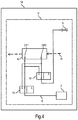
- Fig.4 shows a partial diagram of a clothes dryer 14 according to a second embodiment.
- the clothes dryer 14 differs from clothes dryer 1 by a different set of directional control valves, as shown by the components of detail V.
- the other components may be the same for all embodiments.
- the detail V of clothes dryer 14 shows two 3/2 directional control valves 15 and 16 instead of the one 4/2 directional control valve 8 for reversing the flow direction of the refrigerant R within the condenser 4.
- the 4/2 directional control valve 9 for reversing the flow direction of the refrigerant R within the evaporator 6 may be replaced by two 3/2 directional control valves in an analogous manner (not shown).
- valve positions of the 3/2 directional control valves 15 and 16 are set such that the condenser 4 is in a counter-flow state.
- Fig.5 shows the components of fig.4 with the 3/2 directional control valves 15 and 16 being set such that the condenser 4 is in a parallel-flow state.
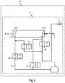
- Fig.6 shows detail V of a clothes dryer 17 according to a third embodiment.
- the clothes dryer 17 differs from clothes dryer 1 and from clothes dryer 14 by yet another set of directional control valves.
- the detail V of clothes dryer 17 shows four 2/2 directional control valves 18, 19, 20 and 21 for reversing the flow direction of the refrigerant R within the condenser 4 instead of, e.g., the one 4/2 directional control valve 8.
- the evaporator 6 may be connected to such a set of 2/2 directional control valves 18, 19, 20 and 21 in an analogous manner (not shown).
- valve positions of four 2/2 directional control valves 18, 19, 20 and 21 are set such that the condenser 4 is in a counter-flow state.
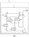
- Fig.7 shows the components of fig.4 with the four 2/2 directional control valves 18, 19, 20 and 21 being set such that the condenser 4 is in a parallel-flow state.
Landscapes
- Engineering & Computer Science (AREA)
- Textile Engineering (AREA)
- Physics & Mathematics (AREA)
- Mechanical Engineering (AREA)
- Thermal Sciences (AREA)
- General Engineering & Computer Science (AREA)
- Detail Structures Of Washing Machines And Dryers (AREA)
Description
- The invention relates to a household appliance comprising a heat pump, the heat pump comprising a compressor, a condenser, an expansion device, and an evaporator. The invention also relates to a method for operating such a household appliance. The invention is particularly useful for laundry drying appliances.
- The use of the heat pumps in home appliances with drying functions is steadily growing. A heat pump typically comprises a heat pump circuit having a compressor, a condenser, an expansion device, and an evaporator connected by refrigerant lines to form a refrigerant circuit. Such a heat pump is also called a compressor heat pump.
- In these home appliances, a flow of dry process air applied to a load to be dried is usually heated by means of the condenser. The process air is usually propelled by a fan. Dehumidification is effected by cooling the humid process air by passing it over the cold surfaces of the evaporator. The condenser and the evaporator thus act as heat exchangers to exchange heat between the refrigerant and the process air. The temperature difference between the condenser and the evaporator is produced due to compressing a previously evaporated refrigerant in a superheated gas state, which is able to condense at the condenser due to being cooled down by the dry air, which is then expanded by the expansion device, and which is then evaporated again at the evaporator by the humid air coming from the load to be dried.
- In some cases - for example when using an AC compressor - the heat exchange capacity of the heat exchangers cannot be regulated by adapting the operation of the compressor, even if, at some phases of the drying cycle, lower capacities of the evaporator and/or of the condenser would benefit the global performance of the household appliance.
- Laundry drying appliances comprising heat pumps are generally known. For example,
WO 2014/067797 A2 discloses a laundry drying appliance that has a fan for moving process air, a heat pump and a temperature measurement device, wherein the laundry drying appliance is designed to set a ventilation output of the fan depending on at least one temperature detected at the heat pump by means of the temperature measurement device. -
WO 2013/144875 A1 discloses a heat exchanger for a laundry drying appliance which comprises at least one set of pipes, each set of pipes comprising at least two pipes, wherein the pipes are mechanically connected by at least one connection structure (also called a "finned tube heat exchanger"). At least two pipes are made from different metals having a different thermal expansion coefficient; at least two of the pipes having a different thermal expansion coefficient are joined by a soldered joint (lib) or by a brazed joint. At the joint (lib) of the two pipes, the pipe made of the metal having a lower thermal expansion coefficient is inserted into the pipe made of the metal having a higher thermal expansion coefficient. Also disclosed is a household appliance, in particular clothes treatment appliance, comprising at least one such heat exchanger, and a method for manufacturing such heat exchanger. -
EP 2 466 001 A1 -
EP 1 493 860 A2 - It is an object of the present invention to at least partially overcome the problems associated with the prior art. It is a particular object of the present invention to provide an easily incorporable means to regulate a capacity of the heat pump heat exchangers independently from operating the compressor.
- The object is achieved according to the features of the independent claims. Advantageous embodiments can be found, e.g., in the dependent claims and/or in the description.
- The object is achieved according to a household appliance comprising a heat pump, the heat pump comprising a compressor, a condenser, an expansion device, and an evaporator, wherein the household appliance further comprises at least one refrigerant redirection device to reverse a flow direction of a refrigerant through the condenser and/or through the evaporator.
- This gives the advantage that a flow direction of the refrigerant through the evaporator and/or through the condenser is reversed. Particularly, this household appliance allows reversing the use of ports of the condenser and/or evaporator as inlet and outlet ports. The flow direction of the refrigerant in the refrigerant circuit / heat pump, however, is not reversed. By this, the heat exchange conditions between the refrigerant and the surrounding of the evaporator and/or the condenser (e.g. process air) are changed which in turn changes the heat exchange ability or capacity of the evaporator and/or the condenser. Also, refrigerant redirection devices are robust with low complexity, are cost-effective, and are easy to integrate into existing household appliances.
- Furthermore, the refrigerant redirection device is at least one directional control valve, wherein, in a first valve position of the at least one directional control valve, its first port is connected to its second port and its third port is connected to its fourth port, and wherein, in a second valve position, its first port is connected to its third port and its second port is connected to its fourth port. This enables a particular compact and robust redirection device. Furthermore, the use of a valve enables a particularly simple assembly process since a valve can easily be integrated as part of the heat pump circuit of, e.g., an existing dryer or washer-dryer platform.
- Also, the at least one directional control valve is a 4/2 directional control valve (4-way valve). Such a valve may be implemented in a specially compact and robust design.
- Specifically, the household appliance comprises a first 4/2 directional control valve wherein its first port is connected to an outlet of the compressor, its second port is connected to a first port of the condenser, its third port is connected to a second port of the condenser, and its fourth port is connected to an inlet of the expansion device. This enables a flow reversal in the condenser. Thus, in the first valve position, the refrigerant can flow from the compressor to the first port of the condenser, through the condenser to its second port, and from there to the expansion device. In the second valve position, the refrigerant can flow from the compressor to the second port of the condenser, through the condenser to its first port, and from there to the expansion device.
- Additionally, the household appliance comprises a second 4/2 directional control valve wherein its first port is connected to an outlet of the expansion device, its second port is connected to a first port of the evaporator, its third port is connected to a second port of the evaporator, and its fourth port is connected to an inlet of the compressor. This enables a flow reversal in the evaporator. Thus, in the first valve position, the refrigerant can flow from the expansion device to the first port of the evaporator, through the evaporator to its second port, and from there to the compressor. In the second valve position, the refrigerant can flow from the expansion device to the second port of the evaporator, through the evaporator to its first port, and from there to the compressor.
- The compressor, the condenser, the expansion device, and the evaporator may be connected in the described order (e.g. by refrigerant lines) to form a closed refrigerant circuit. The expansion device may be a thermal expansion valve.
- This household appliance may comprise only a refrigerant redirection device for the condenser, only a refrigerant redirection device for the evaporator, or both.
- It is an embodiment that the compressor is an AC compressor. It is particularly advantageous to employ the at least one refrigerant redirection device in combination with such a compressor since AC compressors are rugged and low-cost components. It may be more cost effective to combine an AC compressor with at least one refrigerant redirection device than to use a compressor powered by, e.g., a BLDC motor. Generally, the at least one refrigerant redirection device can also advantageously be used in combination with other types of compressors, even with BLDC-powered compressors.
- The valve may be an electrically controlled valve, e.g. actuated by a solenoid or a motor.
- It is an embodiment that the household appliance comprises a control device (e.g. a central control unit) that is adapted to control or set the valve positions of the least one directional control valve for the evaporator and/or for the condenser. The setting may be based on the desired capacity of the evaporator and/or of the condenser as heat exchangers Thus, the at least one directional control valve (or, more generally, the at least one refrigerant redirection device) may be automatically controlled to change the capacity of the evaporator and/or of the condenser in accordance with needs to reduce an energy consumption of the household appliance. The control device may, e.g., switch at least one refrigerant redirection device based on reaching or performing one or more phases of an operation process or cycle, e. g. a drying cycle. Alternatively or additionally, the control device may switch the at least one refrigerant redirection device based on reaching at least one pre-defined condition, e. g. at least one measured condition, e. g. a threshold value for a temperature, a pressure, a laundry moisture value etc. To this effect, the control device may be connected to at least one sensor, e.g. a temperature sensor for the process air, a temperature sensor for the compressor, a temperature sensor for the refrigerant, a pressure sensor for the process air, a pressure sensor for the refrigerant, etc.
- In one embodiment, the control device may automatically determine whether to switch valve positions only for the evaporator, only of the condenser, or for both the evaporator and the condenser (if existing).
- It is an embodiment that the evaporator and/or the condenser are finned tube heat exchangers to exchange heat between the refrigerant and the process air. Such heat exchangers allow high heat transfer efficiencies and are easy to install.
- It is an embodiment that ports of the evaporator and/or the condenser (which act as refrigerant inlets and refrigerant outlets) are positioned at opposite ends of the evaporator and the condenser, respectively, with respect to a flow direction of the process air. This gives the advantageous effect that a flow path of the refrigerant flowing through the evaporator and/or the condenser can be widely and gradually spread along a direction of the process air. This, in turn, allows a noticeable difference in the capacity depending on the flow direction of the refrigerant.
- For example, the first port of the evaporator and/or of the condenser may be positioned at a rear region of a flow path of the process air through this component and the second port is positioned at a front of this flow path. Then, the refrigerant enters the component through the first port and thus initially exchanges heat with process air that has already been flowing through the evaporator and/or condenser. By flowing to the second port, the refrigerant flows in a general direction opposite to the direction of the process air. Such a state may also be called a "counter-flow state".
- In contrast, in a "parallel-flow" state, the refrigerant enters through the second port and thus initially exchanges heat with process air just arriving at the evaporator and/or condenser which may have a higher and lower temperature, respectively, as compared to the process air that has already been flowing through the evaporator and/or condenser. In the parallel-flow state, the refrigerant thus flows in the same general direction as the process air.
- It is an embodiment that at least one 4/2 directional control valve is exactly one 4/2 control valve. Such a valve may be implemented in a specially compact and robust design. Generally, however, other types of valves and/or combinations of other valves may be used, e.g. two 3/2 directional control valves (3-way valves), four 2-way valves etc.
- Thus, it is an embodiment that at least one 4/2 directional control valve comprises two 3/2 control valves. It is also an embodiment that at least one 4/2 directional control valve comprises four 2/2 control valves.
- It is an embodiment that the household appliance is a home appliance having a drying function. In such a household appliance, the at least one refrigerant redirection device can be employed with particularly high energy savings concerning the heat pump circuit during a drying process while obtaining similar drying results.
- It is an embodiment that the household appliance is a clothes or laundry drying appliance, e.g. a clothes dryer or a washer-dryer. The use of the at least one refrigerant redirection device as described above can give especially high energy savings.
- It is an embodiment that the household appliance is a dishwasher.
- It is even an embodiment that the household appliance is a refrigeration device. This embodiment makes use of the effect that employing the at least one refrigerant redirection device as described above not only gives energy savings if a load of the household appliance is to be dried (warmed up or heated up) but also when a load is to be cooled down.
- The object is also achieved by a method for operating a household appliance as described above, the method comprising switching at least one refrigerant redirection device to reverse a flow direction of a refrigerant only through the evaporator and/or through the condenser.
- The method can be embodied and adapted in analogy to the household appliance as described above and gives the same advantages.
- The above described features and advantages of the invention as well as their kind of implementation will now be schematically described in more detail by at least one embodiment in the context of one or more figures.
- Fig.1
- shows a diagram of a clothes dryer according to a first embodiment;
- Fig.2
- shows a cross-sectional side view of a process air channel comprising a condenser in its counter-flow state;
- Fig.3
- shows a cross-sectional side view of a process air channel comprising a condenser in its parallel-flow state;
- Fig.4
- shows a partial diagram of a clothes dryer according to a second embodiment with its condenser in the counter-flow state;
- Fig.5
- shows a partial diagram of the clothes dryer according to the second embodiment with its condenser in the parallel-flow state;
- Fig.6
- shows a partial diagram of a clothes dryer according to a third embodiment with its condenser in the counter-flow state; and
- Fig.7
- shows a partial diagram of the clothes dryer according to the third embodiment with its condenser in the parallel-flow state.
-
Fig.1 shows a diagram of a household appliance in form of aclothes dryer 1. Theclothes dryer 1 comprises aheat pump 2, theheat pump 2 comprising anAC compressor 3, a condenser 4, an expansion device in form of athermal expansion valve 5, and anevaporator 6 connected byrefrigerant lines 7. Theheat pump 2 further comprises a refrigerant redirection device in form of a first 4/2directional control valve 8 to reverse a flow direction of a refrigerant R through the condenser 4. Theheat pump 2 also comprises a refrigerant redirection device in form of a second 4/2directional control valve 9 to reverse a flow direction of the refrigerant R through theevaporator 6. Thecontrol valves evaporator 6 may be of the same basic type (e. g., a finned tube heat exchanger) but may vary in their concrete design (e. g. regarding the number, diameter, and/or material of their pipes etc.). - Each of the
control valves - Regarding the first
directional control valve 8, its first port P1 is connected to an outlet of theAC compressor 3, its second port P2 is connected to a first port CP1 of the condenser 4, its third port P3 is connected to a second port CP2 of the condenser 4, and its fourth port P4 is connected to an inlet of thethermal expansion valve 5. - Regarding the second
directional control valve 9, its first port P1 is connected to an outlet of thethermal expansion valve 5, its second port P2 is connected to a first port EP1 of theevaporator 6, its third port P3 is connected to a second port EP2 of theevaporator 6, and its fourth port P4 is connected to an inlet of theevaporator 6. - For both valve positions, the refrigerant R moves from the
compressor 3 to the firstdirectional control valve 8, to the condenser 4, back through the firstdirectional control valve 8, to thethermal expansion valve 5, to the seconddirectional control valve 9, to theevaporator 6, again through the seconddirectional control valve 9, and back to thecompressor 3. By switching thecontrol valves evaporator 6, respectively, is reversed. - The valve positions of the
control valves central control unit 10. The shown valve positions of thecontrol valves evaporator 6 in their counter-flow state. - The
clothes dryer 1 further comprises aprocess air circuit 11 for circulating process air A. Theprocess air circuit 11 comprises - in that order in a flow direction of the process air A - aclothes drum 12, theevaporator 6 acting as a cooling unit to cool down and thus to dehumidify the humid process air A coming from thedrum 12, the condenser 4 acting as heating unit to heat up the dehumidified process air A coming from theevaporator 6, and afan 13 to move the process air A. Thefan 13 may be placed at another position within theprocess air circuit 11, e.g. between thedrum 12 and theevaporator 6. The condenser 4 and theevaporator 6 are shaped as heat exchangers to exchange heat between the process air A and the refrigerant R. Theprocess air circuit 11 may comprise an additional heater (not shown), e. g. in the form of an electrical heating resistance, a heating light (infrared heating lamp) etc., to support heating up the dried process air A. - The
central control unit 10 may further be used to controlcomponents process air circuit 11. Thecentral control unit 10 may also be used to control other functions of theclothes dryer 1, e.g. a door latch etc. Thecentral control unit 10 may be connected to at least one sensor (not shown). -
Fig.2 shows a cross-sectional side view of theprocess air channel 11 at a section comprising the condenser 4. The condenser 4 may be of a finned tube type, e. g. as disclosed inWO 2013/144875 A1 . The pipes are shown as circles, denoted by numbers "1" to "49", with the pipe numbered "43" not being used. Thus, there are 48 parallel pipes or tubes that are aligned perpendicular to the flow direction of the process air A. The pipes numbered "7" and "49" are the condenser's 4 second port CP2 and first port CP1, respectively. - The condenser 4 is shown in its counter-flow state in which the first port CP1 (pipe "49") acts as a refrigerant input while the second port CP2 (pipe "7") acts as a refrigerant output. The first port CP1 and the second port CP2 of the condenser 4 are positioned at opposite ends of the condenser 4 regarding the flow direction of the process air A. While the second port CP2 is positioned at a front region of the condenser 4, the first port CP1 is positioned at a rear region. Thus, the refrigerant R is entering the condenser 4 at its rear and then moves / flows to its front. This counter-flow state achieves a more effective heat exchange (higher heat transfer rate) than the parallel-flow state in which the second port CP2 acts as the refrigerant input while the first port CP1 acts as the refrigerant output. The parallel-flow state is shown in
Fig.3 . - The same may hold in analogy for the
evaporator 6 which may also be a finned tube heat exchanger. In its counter-flow state, its first port EP1 - which then acts as a refrigerant input - is advantageously positioned at a rear of theevaporator 6 with respect to a flow direction of the process air A. Its second port EP2 - which then acts as a refrigerant output - is positioned at the front of theevaporator 6. Accordingly, in its parallel-flow state, its first port EP1 acts as the refrigerant output while its second port EP2 acts as the refrigerant input. - The
evaporator 6 may have less or more pipes than the condenser 4, e. g. 20 parallel pipes. - Compared to a "normal" or "base" configuration in which both the
evaporator 6 and the condenser 4 are in their counter-flow states, the reversal of the flow direction of the refrigerant R in theevaporator 6 leads to only a slightly lower superheating and slightly higher subcooling of the refrigerant R. A condensation temperature and an evaporation temperature are only slightly higher such that the refrigerant cycle is moved to slightly higher working pressures, too. Reversing theevaporator 6 has neither a significant effect on the cooling power, i.e. on the power used for cooling down the humid process air A, nor on the heating power, i.e. on the power used for heating up the dry process air A. A compressor power, i.e. a power used up by thecompressor 3, is only marginally higher (approx. 1% to 3%) while a mass flow rate of the refrigerant R is also only marginally higher (approx. 2% to 5%). - A reversal of the flow direction of the refrigerant R only in the condenser 4, however, leads to a significant decrease of the condensation temperature and the evaporation temperature as compared to the base configuration. The heat pump cycle thus works at lower working pressures. The subcooling is almost negligible but the superheating strongly increases. A decrease higher than 25% is obtained for the cooling power and the heating power. The compressor power is also lower (approx. 10%) as compared to the base configuration.
- When the flow directions of the refrigerant R in both the condenser 4 and
evaporator 6 are reversed (so that they both are in their parallel-flow state), the results are similar to the reversal of the flow direction in only the condenser 4. Compared to that, the condensation temperature and the evaporation temperatures are slightly smaller such that the refrigerant's R cycle is moved to slightly lower working pressures. There is almost no subcooling. The cooling capacity and the heating capacity decrease slightly more as compared to only the condenser 4 being in its parallel-flow state. The compressor power is even lower (approx. 13%) as compared to the base configuration. - Therefore, the reversal of the condenser 4 from its counter-flow state to its parallel-flow state has the highest relative effect.
-
Fig.4 shows a partial diagram of aclothes dryer 14 according to a second embodiment. Theclothes dryer 14 differs fromclothes dryer 1 by a different set of directional control valves, as shown by the components of detail V. The other components (outside detail V) may be the same for all embodiments. - The detail V of
clothes dryer 14 shows two 3/2directional control valves directional control valve 8 for reversing the flow direction of the refrigerant R within the condenser 4. The 4/2directional control valve 9 for reversing the flow direction of the refrigerant R within theevaporator 6 may be replaced by two 3/2 directional control valves in an analogous manner (not shown). - The valve positions of the 3/2
directional control valves -
Fig.5 shows the components offig.4 with the 3/2directional control valves -
Fig.6 shows detail V of aclothes dryer 17 according to a third embodiment. Theclothes dryer 17 differs fromclothes dryer 1 and fromclothes dryer 14 by yet another set of directional control valves. - The detail V of
clothes dryer 17 shows four 2/2directional control valves directional control valve 8. Theevaporator 6 may be connected to such a set of 2/2directional control valves - The valve positions of four 2/2
directional control valves -
Fig.7 shows the components offig.4 with the four 2/2directional control valves - Of course, the invention is not restricted to the described embodiments.
-
- 1
- Clothes dryer
- 2
- Heat pump
- 3
- Compressor
- 4
- Condenser
- 5
- Thermal expansion valve
- 6
- Evaporator
- 7
- Refrigerant line
- 8
- First 4/2 directional control valve
- 9
- Second 4/2 directional control valve
- 10
- Central control unit
- 11
- Process air circuit
- 12
- Drum
- 13
- Fan
- 14
- Clothes dryer
- 15
- 3/2 directional control valve
- 16
- 3/2 directional control valve
- 17
- Clothes dryer
- 18
- 2/2 directional control valve
- 19
- 2/2 directional control valve
- 20
- 2/2 directional control valve
- 21
- 2/2 directional control valve
- A
- Process air
- CP1
- First port of the condenser
- CP2
- Second port of the condenser
- EP1
- First port of the evaporator
- EP2
- Second port of the evaporator
- P1-P4
- Ports of the 4/2 directional control valve
- R
- Refrigerant
Claims (12)
- A household appliance (1; 14; 17) comprising a heat pump (2), the heat pump (2) comprising a compressor (3), a condenser (4), an expansion device (5), and an evaporator (6) connected in series by a refrigerant circuit (7), wherein the household appliance (1) further comprises- at least one refrigerant redirection device (8, 9; 15, 16; 18-21) to reverse a flow direction of a refrigerant (R) through the condenser (4) and/or through the evaporator (6)characterized in that
the household appliance (1; 14; 17) comprises only a refrigerant redirection device (8) for the condenser (4), only a refrigerant redirection device for the evaporator (6), or both, reversing the use of ports of the condenser (4) and/or evaporator (6) inlet and outlet ports, such that the flow direction of the refrigerant (R) through the condenser (4) and/or
the evaporator (6), respectively, is reversed but the flow direction of the refrigerant in the heat pump is not reversed. - The household appliance (1; 14; 17) according to claim 1 wherein the compressor (3) is an AC compressor.
- The household appliance (1; 14; 17) according to any of the preceding claims wherein the refrigerant redirection device comprises at least one directional control valve (8, 9; 15, 16; 18-21), wherein,- in a first valve position of the at least one directional control valve (8, 9), a first port (P1) is connected to a second port (P2) and a third port (P3) is connected to a fourth port (P4), and wherein,- in a second valve position of the at least one directional control valve (8, 9), the first port is (P1) connected to the third port (P3) and the second port (P2) is connected to the fourth port (P4).
- The household appliance (1) according to claim 3, comprising a first 4/2 directional control valve (8) to reverse the flow direction of the refrigerant through the condenser, wherein- the first port (P1) is connected to an outlet of the compressor (3),- the second port (P2) is connected to a first port (CP1) of the condenser (4),- the third port (P3) is connected to a second port (CP2) of the condenser (4), and- the fourth port (P4) is connected to an inlet of the expansion device (5).
- The household appliance (1) according to any of the claims 3 to 4 comprising a second 4/2 directional control valve (9) to reverse the flow direction of the refrigerant through the evaporator, wherein- a first port (P1) is connected to an outlet of the expansion device (5),- a second port (P2) is connected to a first port (EP1) of the evaporator (6),- a third port (P3) is connected to a second port (EP2) of the evaporator (6), and- a fourth port (P4) is connected to an inlet of the compressor (3).
- The household appliance (1; 14; 17) according to any of the claims 3 to 5 wherein the household appliance (1) comprises a control device (10) that is adapted to control the valve positions of the least one directional control valve (8, 9; 15, 16; 18-21) for the condenser (4) and/or for the evaporator (6) based on their desired capacity as heat exchangers.
- The household appliance (1; 14; 17) according to any of the preceding claims wherein the condenser (4) and/or the evaporator (6) are finned tube heat exchangers to exchange heat between the refrigerant (R) flowing through it and process air (A).
- The household appliance (1; 14; 17) according to claim 7 wherein a refrigerant inlet port (CP1) and a refrigerant outlet port (CP2) of the condenser (4) and/or a refrigerant inlet port (EP1) and a refrigerant outlet port (EP2) of the evaporator (6) are positioned at opposite ends with respect to a flow direction of the process air (A).
- The household appliance (1; 14; 17) according to any of the preceding claims wherein the household appliance (1) is a clothes drying appliance.
- The household appliance according to any of the preceding claims wherein the household appliance is a dishwasher.
- The household appliance according to any of the preceding claims wherein the household appliance is a refrigeration device.
- A method for operating a household appliance (1; 14; 17) according to any of the preceding claims comprising a heat pump (2), the heat pump (2) comprising a compressor (3), a condenser (4), an expansion device (5), and an evaporator (6) connected in series by a refrigerant circuit (7), wherein the household appliance further comprises at least one refrigerant redirection device (8, 9; 15, 16; 18-21), the method comprising switching at least one refrigerant redirection device (8, 9; 15, 16; 18-21) to reverse a flow direction of a refrigerant (R) through the evaporator (6) and/or through the condenser (4).
Priority Applications (4)
| Application Number | Priority Date | Filing Date | Title |
|---|---|---|---|
| EP16382263.8A EP3255202B1 (en) | 2016-06-09 | 2016-06-09 | Household appliance comprising a heat pump |
| PL16382263T PL3255202T3 (en) | 2016-06-09 | 2016-06-09 | Household appliance comprising a heat pump |
| PL17173984T PL3255203T3 (en) | 2016-06-09 | 2017-06-01 | Household appliance comprising a heat pump |
| EP17173984.0A EP3255203B1 (en) | 2016-06-09 | 2017-06-01 | Household appliance comprising a heat pump |
Applications Claiming Priority (1)
| Application Number | Priority Date | Filing Date | Title |
|---|---|---|---|
| EP16382263.8A EP3255202B1 (en) | 2016-06-09 | 2016-06-09 | Household appliance comprising a heat pump |
Publications (2)
| Publication Number | Publication Date |
|---|---|
| EP3255202A1 EP3255202A1 (en) | 2017-12-13 |
| EP3255202B1 true EP3255202B1 (en) | 2019-11-13 |
Family
ID=56132876
Family Applications (1)
| Application Number | Title | Priority Date | Filing Date |
|---|---|---|---|
| EP16382263.8A Active EP3255202B1 (en) | 2016-06-09 | 2016-06-09 | Household appliance comprising a heat pump |
Country Status (2)
| Country | Link |
|---|---|
| EP (1) | EP3255202B1 (en) |
| PL (1) | PL3255202T3 (en) |
Cited By (1)
| Publication number | Priority date | Publication date | Assignee | Title |
|---|---|---|---|---|
| EP3896214A1 (en) | 2020-04-17 | 2021-10-20 | BSH Hausgeräte GmbH | Home appliance dryer comprising a heat pump circuit having a compressor, and method of operating such home appliance dryer |
Families Citing this family (1)
| Publication number | Priority date | Publication date | Assignee | Title |
|---|---|---|---|---|
| EP4498884A1 (en) * | 2022-03-30 | 2025-02-05 | Electrolux Appliances Aktiebolag | Articles treatment appliance for treating articles and method for operating such articles treatment appliance |
Family Cites Families (4)
| Publication number | Priority date | Publication date | Assignee | Title |
|---|---|---|---|---|
| JP2005024113A (en) * | 2003-06-30 | 2005-01-27 | Sanyo Electric Co Ltd | Dryer |
| ITTO20101018A1 (en) * | 2010-12-20 | 2012-06-21 | Indesit Co Spa | MACHINE FOR DRYING OF LINEN FOR HOME USE |
| EP2831528A1 (en) | 2012-03-30 | 2015-02-04 | BSH Bosch und Siemens Hausgeräte GmbH | Heat exchanger, household appliance comprising such heat exchanger and method for manufacturing such heat exchanger |
| DE102012219975A1 (en) | 2012-10-31 | 2014-04-30 | BSH Bosch und Siemens Hausgeräte GmbH | Clothes drying machine with heat pump |
-
2016
- 2016-06-09 PL PL16382263T patent/PL3255202T3/en unknown
- 2016-06-09 EP EP16382263.8A patent/EP3255202B1/en active Active
Non-Patent Citations (1)
| Title |
|---|
| None * |
Cited By (1)
| Publication number | Priority date | Publication date | Assignee | Title |
|---|---|---|---|---|
| EP3896214A1 (en) | 2020-04-17 | 2021-10-20 | BSH Hausgeräte GmbH | Home appliance dryer comprising a heat pump circuit having a compressor, and method of operating such home appliance dryer |
Also Published As
| Publication number | Publication date |
|---|---|
| PL3255202T3 (en) | 2020-07-13 |
| EP3255202A1 (en) | 2017-12-13 |
Similar Documents
| Publication | Publication Date | Title |
|---|---|---|
| KR101355689B1 (en) | Air conditioning system and accumulator thereof | |
| JP6723354B2 (en) | Refrigeration cycle equipment | |
| EP2489774B1 (en) | A heat pump laundry dryer | |
| KR101147268B1 (en) | Heat pump system for heating/cooling and providing hot water and Control method thereof | |
| EP2171150B1 (en) | A washer/dryer | |
| CN112119273B (en) | Refrigeration cycle device | |
| WO2011010473A1 (en) | Heat pump device | |
| EP2735819A2 (en) | Refrigeration cycle apparatus and warm water producing apparatus having refrigeration cycle apparatus | |
| JPWO2020208776A1 (en) | Air conditioner | |
| WO2018193518A1 (en) | Air conditioner | |
| KR20110084046A (en) | Refrigerant system and control method | |
| JP6964776B2 (en) | Refrigeration cycle equipment | |
| WO2012121326A1 (en) | Binary refrigeration cycle device | |
| WO2019064335A1 (en) | Refrigeration cycle device | |
| JP2002089980A (en) | Air conditioner | |
| EP3255202B1 (en) | Household appliance comprising a heat pump | |
| EP3255203B1 (en) | Household appliance comprising a heat pump | |
| WO2006013938A1 (en) | Freezing apparatus | |
| KR100675900B1 (en) | Refrigeration air conditioning system | |
| EP3698084A1 (en) | Air-conditioning apparatus | |
| WO2015132951A1 (en) | Refrigeration device | |
| EP2976454A1 (en) | Appliance for drying laundry | |
| JP6581822B2 (en) | Air conditioner | |
| KR20100137050A (en) | Refrigeration air conditioning system | |
| CN104976837B (en) | Air conditioner |
Legal Events
| Date | Code | Title | Description |
|---|---|---|---|
| PUAI | Public reference made under article 153(3) epc to a published international application that has entered the european phase |
Free format text: ORIGINAL CODE: 0009012 |
|
| STAA | Information on the status of an ep patent application or granted ep patent |
Free format text: STATUS: THE APPLICATION HAS BEEN PUBLISHED |
|
| AK | Designated contracting states |
Kind code of ref document: A1 Designated state(s): AL AT BE BG CH CY CZ DE DK EE ES FI FR GB GR HR HU IE IS IT LI LT LU LV MC MK MT NL NO PL PT RO RS SE SI SK SM TR |
|
| AX | Request for extension of the european patent |
Extension state: BA ME |
|
| STAA | Information on the status of an ep patent application or granted ep patent |
Free format text: STATUS: REQUEST FOR EXAMINATION WAS MADE |
|
| 17P | Request for examination filed |
Effective date: 20180613 |
|
| RBV | Designated contracting states (corrected) |
Designated state(s): AL AT BE BG CH CY CZ DE DK EE ES FI FR GB GR HR HU IE IS IT LI LT LU LV MC MK MT NL NO PL PT RO RS SE SI SK SM TR |
|
| STAA | Information on the status of an ep patent application or granted ep patent |
Free format text: STATUS: EXAMINATION IS IN PROGRESS |
|
| 17Q | First examination report despatched |
Effective date: 20190115 |
|
| GRAP | Despatch of communication of intention to grant a patent |
Free format text: ORIGINAL CODE: EPIDOSNIGR1 |
|
| STAA | Information on the status of an ep patent application or granted ep patent |
Free format text: STATUS: GRANT OF PATENT IS INTENDED |
|
| INTG | Intention to grant announced |
Effective date: 20190628 |
|
| GRAS | Grant fee paid |
Free format text: ORIGINAL CODE: EPIDOSNIGR3 |
|
| GRAA | (expected) grant |
Free format text: ORIGINAL CODE: 0009210 |
|
| STAA | Information on the status of an ep patent application or granted ep patent |
Free format text: STATUS: THE PATENT HAS BEEN GRANTED |
|
| AK | Designated contracting states |
Kind code of ref document: B1 Designated state(s): AL AT BE BG CH CY CZ DE DK EE ES FI FR GB GR HR HU IE IS IT LI LT LU LV MC MK MT NL NO PL PT RO RS SE SI SK SM TR |
|
| REG | Reference to a national code |
Ref country code: CH Ref legal event code: EP Ref country code: AT Ref legal event code: REF Ref document number: 1201756 Country of ref document: AT Kind code of ref document: T Effective date: 20191115 |
|
| REG | Reference to a national code |
Ref country code: DE Ref legal event code: R096 Ref document number: 602016024217 Country of ref document: DE |
|
| REG | Reference to a national code |
Ref country code: IE Ref legal event code: FG4D |
|
| REG | Reference to a national code |
Ref country code: NL Ref legal event code: MP Effective date: 20191113 |
|
| REG | Reference to a national code |
Ref country code: LT Ref legal event code: MG4D |
|
| PG25 | Lapsed in a contracting state [announced via postgrant information from national office to epo] |
Ref country code: GR Free format text: LAPSE BECAUSE OF FAILURE TO SUBMIT A TRANSLATION OF THE DESCRIPTION OR TO PAY THE FEE WITHIN THE PRESCRIBED TIME-LIMIT Effective date: 20200214 Ref country code: NL Free format text: LAPSE BECAUSE OF FAILURE TO SUBMIT A TRANSLATION OF THE DESCRIPTION OR TO PAY THE FEE WITHIN THE PRESCRIBED TIME-LIMIT Effective date: 20191113 Ref country code: LT Free format text: LAPSE BECAUSE OF FAILURE TO SUBMIT A TRANSLATION OF THE DESCRIPTION OR TO PAY THE FEE WITHIN THE PRESCRIBED TIME-LIMIT Effective date: 20191113 Ref country code: FI Free format text: LAPSE BECAUSE OF FAILURE TO SUBMIT A TRANSLATION OF THE DESCRIPTION OR TO PAY THE FEE WITHIN THE PRESCRIBED TIME-LIMIT Effective date: 20191113 Ref country code: BG Free format text: LAPSE BECAUSE OF FAILURE TO SUBMIT A TRANSLATION OF THE DESCRIPTION OR TO PAY THE FEE WITHIN THE PRESCRIBED TIME-LIMIT Effective date: 20200213 Ref country code: LV Free format text: LAPSE BECAUSE OF FAILURE TO SUBMIT A TRANSLATION OF THE DESCRIPTION OR TO PAY THE FEE WITHIN THE PRESCRIBED TIME-LIMIT Effective date: 20191113 Ref country code: SE Free format text: LAPSE BECAUSE OF FAILURE TO SUBMIT A TRANSLATION OF THE DESCRIPTION OR TO PAY THE FEE WITHIN THE PRESCRIBED TIME-LIMIT Effective date: 20191113 Ref country code: PT Free format text: LAPSE BECAUSE OF FAILURE TO SUBMIT A TRANSLATION OF THE DESCRIPTION OR TO PAY THE FEE WITHIN THE PRESCRIBED TIME-LIMIT Effective date: 20200313 Ref country code: NO Free format text: LAPSE BECAUSE OF FAILURE TO SUBMIT A TRANSLATION OF THE DESCRIPTION OR TO PAY THE FEE WITHIN THE PRESCRIBED TIME-LIMIT Effective date: 20200213 |
|
| PG25 | Lapsed in a contracting state [announced via postgrant information from national office to epo] |
Ref country code: HR Free format text: LAPSE BECAUSE OF FAILURE TO SUBMIT A TRANSLATION OF THE DESCRIPTION OR TO PAY THE FEE WITHIN THE PRESCRIBED TIME-LIMIT Effective date: 20191113 Ref country code: RS Free format text: LAPSE BECAUSE OF FAILURE TO SUBMIT A TRANSLATION OF THE DESCRIPTION OR TO PAY THE FEE WITHIN THE PRESCRIBED TIME-LIMIT Effective date: 20191113 Ref country code: IS Free format text: LAPSE BECAUSE OF FAILURE TO SUBMIT A TRANSLATION OF THE DESCRIPTION OR TO PAY THE FEE WITHIN THE PRESCRIBED TIME-LIMIT Effective date: 20200313 |
|
| PG25 | Lapsed in a contracting state [announced via postgrant information from national office to epo] |
Ref country code: AL Free format text: LAPSE BECAUSE OF FAILURE TO SUBMIT A TRANSLATION OF THE DESCRIPTION OR TO PAY THE FEE WITHIN THE PRESCRIBED TIME-LIMIT Effective date: 20191113 |
|
| PG25 | Lapsed in a contracting state [announced via postgrant information from national office to epo] |
Ref country code: EE Free format text: LAPSE BECAUSE OF FAILURE TO SUBMIT A TRANSLATION OF THE DESCRIPTION OR TO PAY THE FEE WITHIN THE PRESCRIBED TIME-LIMIT Effective date: 20191113 Ref country code: RO Free format text: LAPSE BECAUSE OF FAILURE TO SUBMIT A TRANSLATION OF THE DESCRIPTION OR TO PAY THE FEE WITHIN THE PRESCRIBED TIME-LIMIT Effective date: 20191113 Ref country code: CZ Free format text: LAPSE BECAUSE OF FAILURE TO SUBMIT A TRANSLATION OF THE DESCRIPTION OR TO PAY THE FEE WITHIN THE PRESCRIBED TIME-LIMIT Effective date: 20191113 Ref country code: ES Free format text: LAPSE BECAUSE OF FAILURE TO SUBMIT A TRANSLATION OF THE DESCRIPTION OR TO PAY THE FEE WITHIN THE PRESCRIBED TIME-LIMIT Effective date: 20191113 Ref country code: DK Free format text: LAPSE BECAUSE OF FAILURE TO SUBMIT A TRANSLATION OF THE DESCRIPTION OR TO PAY THE FEE WITHIN THE PRESCRIBED TIME-LIMIT Effective date: 20191113 |
|
| REG | Reference to a national code |
Ref country code: DE Ref legal event code: R097 Ref document number: 602016024217 Country of ref document: DE |
|
| REG | Reference to a national code |
Ref country code: AT Ref legal event code: MK05 Ref document number: 1201756 Country of ref document: AT Kind code of ref document: T Effective date: 20191113 |
|
| PG25 | Lapsed in a contracting state [announced via postgrant information from national office to epo] |
Ref country code: SK Free format text: LAPSE BECAUSE OF FAILURE TO SUBMIT A TRANSLATION OF THE DESCRIPTION OR TO PAY THE FEE WITHIN THE PRESCRIBED TIME-LIMIT Effective date: 20191113 Ref country code: SM Free format text: LAPSE BECAUSE OF FAILURE TO SUBMIT A TRANSLATION OF THE DESCRIPTION OR TO PAY THE FEE WITHIN THE PRESCRIBED TIME-LIMIT Effective date: 20191113 |
|
| PLBE | No opposition filed within time limit |
Free format text: ORIGINAL CODE: 0009261 |
|
| STAA | Information on the status of an ep patent application or granted ep patent |
Free format text: STATUS: NO OPPOSITION FILED WITHIN TIME LIMIT |
|
| 26N | No opposition filed |
Effective date: 20200814 |
|
| PG25 | Lapsed in a contracting state [announced via postgrant information from national office to epo] |
Ref country code: SI Free format text: LAPSE BECAUSE OF FAILURE TO SUBMIT A TRANSLATION OF THE DESCRIPTION OR TO PAY THE FEE WITHIN THE PRESCRIBED TIME-LIMIT Effective date: 20191113 Ref country code: AT Free format text: LAPSE BECAUSE OF FAILURE TO SUBMIT A TRANSLATION OF THE DESCRIPTION OR TO PAY THE FEE WITHIN THE PRESCRIBED TIME-LIMIT Effective date: 20191113 |
|
| PG25 | Lapsed in a contracting state [announced via postgrant information from national office to epo] |
Ref country code: IT Free format text: LAPSE BECAUSE OF FAILURE TO SUBMIT A TRANSLATION OF THE DESCRIPTION OR TO PAY THE FEE WITHIN THE PRESCRIBED TIME-LIMIT Effective date: 20191113 Ref country code: MC Free format text: LAPSE BECAUSE OF FAILURE TO SUBMIT A TRANSLATION OF THE DESCRIPTION OR TO PAY THE FEE WITHIN THE PRESCRIBED TIME-LIMIT Effective date: 20191113 |
|
| REG | Reference to a national code |
Ref country code: CH Ref legal event code: PL |
|
| PG25 | Lapsed in a contracting state [announced via postgrant information from national office to epo] |
Ref country code: LU Free format text: LAPSE BECAUSE OF NON-PAYMENT OF DUE FEES Effective date: 20200609 |
|
| REG | Reference to a national code |
Ref country code: BE Ref legal event code: MM Effective date: 20200630 |
|
| PG25 | Lapsed in a contracting state [announced via postgrant information from national office to epo] |
Ref country code: CH Free format text: LAPSE BECAUSE OF NON-PAYMENT OF DUE FEES Effective date: 20200630 Ref country code: LI Free format text: LAPSE BECAUSE OF NON-PAYMENT OF DUE FEES Effective date: 20200630 Ref country code: IE Free format text: LAPSE BECAUSE OF NON-PAYMENT OF DUE FEES Effective date: 20200609 Ref country code: FR Free format text: LAPSE BECAUSE OF NON-PAYMENT OF DUE FEES Effective date: 20200630 |
|
| PG25 | Lapsed in a contracting state [announced via postgrant information from national office to epo] |
Ref country code: BE Free format text: LAPSE BECAUSE OF NON-PAYMENT OF DUE FEES Effective date: 20200630 |
|
| PG25 | Lapsed in a contracting state [announced via postgrant information from national office to epo] |
Ref country code: TR Free format text: LAPSE BECAUSE OF FAILURE TO SUBMIT A TRANSLATION OF THE DESCRIPTION OR TO PAY THE FEE WITHIN THE PRESCRIBED TIME-LIMIT Effective date: 20191113 Ref country code: MT Free format text: LAPSE BECAUSE OF FAILURE TO SUBMIT A TRANSLATION OF THE DESCRIPTION OR TO PAY THE FEE WITHIN THE PRESCRIBED TIME-LIMIT Effective date: 20191113 Ref country code: CY Free format text: LAPSE BECAUSE OF FAILURE TO SUBMIT A TRANSLATION OF THE DESCRIPTION OR TO PAY THE FEE WITHIN THE PRESCRIBED TIME-LIMIT Effective date: 20191113 |
|
| PG25 | Lapsed in a contracting state [announced via postgrant information from national office to epo] |
Ref country code: MK Free format text: LAPSE BECAUSE OF FAILURE TO SUBMIT A TRANSLATION OF THE DESCRIPTION OR TO PAY THE FEE WITHIN THE PRESCRIBED TIME-LIMIT Effective date: 20191113 |
|
| PGFP | Annual fee paid to national office [announced via postgrant information from national office to epo] |
Ref country code: GB Payment date: 20230622 Year of fee payment: 8 |
|
| PGFP | Annual fee paid to national office [announced via postgrant information from national office to epo] |
Ref country code: DE Payment date: 20240630 Year of fee payment: 9 |
|
| PGFP | Annual fee paid to national office [announced via postgrant information from national office to epo] |
Ref country code: PL Payment date: 20240524 Year of fee payment: 9 |
|
| GBPC | Gb: european patent ceased through non-payment of renewal fee |
Effective date: 20240609 |
|
| PG25 | Lapsed in a contracting state [announced via postgrant information from national office to epo] |
Ref country code: GB Free format text: LAPSE BECAUSE OF NON-PAYMENT OF DUE FEES Effective date: 20240609 |
|
| REG | Reference to a national code |
Ref country code: DE Ref legal event code: R119 Ref document number: 602016024217 Country of ref document: DE |
|
| PG25 | Lapsed in a contracting state [announced via postgrant information from national office to epo] |
Ref country code: DE Free format text: LAPSE BECAUSE OF NON-PAYMENT OF DUE FEES Effective date: 20260101 |