EP3255074B1 - Photoelastic polyurethane resin, detection member, robot, and method for producing photoelastic polyurethane resin - Google Patents
Photoelastic polyurethane resin, detection member, robot, and method for producing photoelastic polyurethane resin Download PDFInfo
- Publication number
- EP3255074B1 EP3255074B1 EP16746735.6A EP16746735A EP3255074B1 EP 3255074 B1 EP3255074 B1 EP 3255074B1 EP 16746735 A EP16746735 A EP 16746735A EP 3255074 B1 EP3255074 B1 EP 3255074B1
- Authority
- EP
- European Patent Office
- Prior art keywords
- photoelastic
- polyurethane resin
- constant
- modulus
- sensor
- Prior art date
- Legal status (The legal status is an assumption and is not a legal conclusion. Google has not performed a legal analysis and makes no representation as to the accuracy of the status listed.)
- Active
Links
- 229920005749 polyurethane resin Polymers 0.000 title claims description 144
- 238000001514 detection method Methods 0.000 title claims description 34
- 238000004519 manufacturing process Methods 0.000 title claims description 7
- -1 polytetramethylene Polymers 0.000 claims description 88
- 229920005862 polyol Polymers 0.000 claims description 82
- 229920001228 polyisocyanate Polymers 0.000 claims description 71
- 239000005056 polyisocyanate Substances 0.000 claims description 71
- 125000003118 aryl group Chemical group 0.000 claims description 37
- 125000002887 hydroxy group Chemical group [H]O* 0.000 claims description 37
- XSTXAVWGXDQKEL-UHFFFAOYSA-N Trichloroethylene Chemical compound ClC=C(Cl)Cl XSTXAVWGXDQKEL-UHFFFAOYSA-N 0.000 claims description 35
- 239000000463 material Substances 0.000 claims description 25
- RTZKZFJDLAIYFH-UHFFFAOYSA-N ether Substances CCOCC RTZKZFJDLAIYFH-UHFFFAOYSA-N 0.000 claims description 24
- 239000011342 resin composition Substances 0.000 claims description 24
- 230000009477 glass transition Effects 0.000 claims description 21
- 238000005452 bending Methods 0.000 claims description 20
- 238000000034 method Methods 0.000 claims description 12
- 230000003287 optical effect Effects 0.000 claims description 12
- 238000005259 measurement Methods 0.000 claims description 11
- 239000007795 chemical reaction product Substances 0.000 claims description 6
- 238000000691 measurement method Methods 0.000 claims description 6
- 238000011161 development Methods 0.000 claims description 4
- 239000012788 optical film Substances 0.000 claims description 4
- 229920005989 resin Polymers 0.000 description 102
- 239000011347 resin Substances 0.000 description 102
- 125000004432 carbon atom Chemical group C* 0.000 description 70
- 150000003077 polyols Chemical class 0.000 description 61
- 239000000203 mixture Substances 0.000 description 40
- 238000002156 mixing Methods 0.000 description 30
- 238000003825 pressing Methods 0.000 description 28
- IJGRMHOSHXDMSA-UHFFFAOYSA-N Atomic nitrogen Chemical compound N#N IJGRMHOSHXDMSA-UHFFFAOYSA-N 0.000 description 24
- 239000012948 isocyanate Substances 0.000 description 24
- 150000002513 isocyanates Chemical class 0.000 description 24
- 125000000217 alkyl group Chemical group 0.000 description 23
- 229920002635 polyurethane Polymers 0.000 description 22
- 239000004814 polyurethane Substances 0.000 description 22
- 125000004435 hydrogen atom Chemical group [H]* 0.000 description 20
- ICLCCFKUSALICQ-UHFFFAOYSA-N 1-isocyanato-4-(4-isocyanato-3-methylphenyl)-2-methylbenzene Chemical compound C1=C(N=C=O)C(C)=CC(C=2C=C(C)C(N=C=O)=CC=2)=C1 ICLCCFKUSALICQ-UHFFFAOYSA-N 0.000 description 19
- UPMLOUAZCHDJJD-UHFFFAOYSA-N 4,4'-Diphenylmethane Diisocyanate Chemical compound C1=CC(N=C=O)=CC=C1CC1=CC=C(N=C=O)C=C1 UPMLOUAZCHDJJD-UHFFFAOYSA-N 0.000 description 17
- 239000004014 plasticizer Substances 0.000 description 15
- 238000006243 chemical reaction Methods 0.000 description 14
- 230000000994 depressogenic effect Effects 0.000 description 12
- 125000005442 diisocyanate group Chemical group 0.000 description 12
- 150000002009 diols Chemical class 0.000 description 12
- 229910052757 nitrogen Inorganic materials 0.000 description 12
- 125000001140 1,4-phenylene group Chemical group [H]C1=C([H])C([*:2])=C([H])C([H])=C1[*:1] 0.000 description 11
- 239000003963 antioxidant agent Substances 0.000 description 11
- 230000003078 antioxidant effect Effects 0.000 description 11
- 239000003054 catalyst Substances 0.000 description 11
- 230000004044 response Effects 0.000 description 11
- 125000001931 aliphatic group Chemical group 0.000 description 10
- 230000033228 biological regulation Effects 0.000 description 9
- 125000001997 phenyl group Chemical group [H]C1=C([H])C([H])=C(*)C([H])=C1[H] 0.000 description 9
- ZJCCRDAZUWHFQH-UHFFFAOYSA-N Trimethylolpropane Chemical compound CCC(CO)(CO)CO ZJCCRDAZUWHFQH-UHFFFAOYSA-N 0.000 description 8
- 238000006073 displacement reaction Methods 0.000 description 8
- 230000004043 responsiveness Effects 0.000 description 8
- 238000003756 stirring Methods 0.000 description 8
- 239000000758 substrate Substances 0.000 description 8
- ZWVMLYRJXORSEP-UHFFFAOYSA-N 1,2,6-Hexanetriol Chemical compound OCCCCC(O)CO ZWVMLYRJXORSEP-UHFFFAOYSA-N 0.000 description 7
- 239000002518 antifoaming agent Substances 0.000 description 7
- 230000000052 comparative effect Effects 0.000 description 7
- 229920000909 polytetrahydrofuran Polymers 0.000 description 7
- 238000003860 storage Methods 0.000 description 7
- WYURNTSHIVDZCO-UHFFFAOYSA-N Tetrahydrofuran Chemical compound C1CCOC1 WYURNTSHIVDZCO-UHFFFAOYSA-N 0.000 description 6
- 239000004305 biphenyl Substances 0.000 description 6
- 230000003247 decreasing effect Effects 0.000 description 6
- 230000035945 sensitivity Effects 0.000 description 6
- PUPZLCDOIYMWBV-UHFFFAOYSA-N (+/-)-1,3-Butanediol Chemical compound CC(O)CCO PUPZLCDOIYMWBV-UHFFFAOYSA-N 0.000 description 5
- 235000010290 biphenyl Nutrition 0.000 description 5
- 230000006837 decompression Effects 0.000 description 5
- HBGGXOJOCNVPFY-UHFFFAOYSA-N diisononyl phthalate Chemical compound CC(C)CCCCCCOC(=O)C1=CC=CC=C1C(=O)OCCCCCCC(C)C HBGGXOJOCNVPFY-UHFFFAOYSA-N 0.000 description 5
- XNGIFLGASWRNHJ-UHFFFAOYSA-N o-dicarboxybenzene Natural products OC(=O)C1=CC=CC=C1C(O)=O XNGIFLGASWRNHJ-UHFFFAOYSA-N 0.000 description 5
- 230000005693 optoelectronics Effects 0.000 description 5
- ZUOUZKKEUPVFJK-UHFFFAOYSA-N phenylbenzene Natural products C1=CC=CC=C1C1=CC=CC=C1 ZUOUZKKEUPVFJK-UHFFFAOYSA-N 0.000 description 5
- 239000002904 solvent Substances 0.000 description 5
- SBJCUZQNHOLYMD-UHFFFAOYSA-N 1,5-Naphthalene diisocyanate Chemical compound C1=CC=C2C(N=C=O)=CC=CC2=C1N=C=O SBJCUZQNHOLYMD-UHFFFAOYSA-N 0.000 description 4
- HHPCNRKYVYWYAU-UHFFFAOYSA-N 4-cyano-4'-pentylbiphenyl Chemical group C1=CC(CCCCC)=CC=C1C1=CC=C(C#N)C=C1 HHPCNRKYVYWYAU-UHFFFAOYSA-N 0.000 description 4
- 125000004801 4-cyanophenyl group Chemical group [H]C1=C([H])C(C#N)=C([H])C([H])=C1* 0.000 description 4
- 102100035474 DNA polymerase kappa Human genes 0.000 description 4
- 101710108091 DNA polymerase kappa Proteins 0.000 description 4
- PEDCQBHIVMGVHV-UHFFFAOYSA-N Glycerine Chemical compound OCC(O)CO PEDCQBHIVMGVHV-UHFFFAOYSA-N 0.000 description 4
- 230000007423 decrease Effects 0.000 description 4
- 239000000835 fiber Substances 0.000 description 4
- 238000000465 moulding Methods 0.000 description 4
- 239000003795 chemical substances by application Substances 0.000 description 3
- 238000004140 cleaning Methods 0.000 description 3
- 239000000428 dust Substances 0.000 description 3
- 125000001153 fluoro group Chemical group F* 0.000 description 3
- 238000009472 formulation Methods 0.000 description 3
- NIMLQBUJDJZYEJ-UHFFFAOYSA-N isophorone diisocyanate Chemical compound CC1(C)CC(N=C=O)CC(C)(CN=C=O)C1 NIMLQBUJDJZYEJ-UHFFFAOYSA-N 0.000 description 3
- 125000001624 naphthyl group Chemical group 0.000 description 3
- 230000002093 peripheral effect Effects 0.000 description 3
- 230000000704 physical effect Effects 0.000 description 3
- YLQBMQCUIZJEEH-UHFFFAOYSA-N tetrahydrofuran Natural products C=1C=COC=1 YLQBMQCUIZJEEH-UHFFFAOYSA-N 0.000 description 3
- NNOZGCICXAYKLW-UHFFFAOYSA-N 1,2-bis(2-isocyanatopropan-2-yl)benzene Chemical compound O=C=NC(C)(C)C1=CC=CC=C1C(C)(C)N=C=O NNOZGCICXAYKLW-UHFFFAOYSA-N 0.000 description 2
- OVBFMUAFNIIQAL-UHFFFAOYSA-N 1,4-diisocyanatobutane Chemical compound O=C=NCCCCN=C=O OVBFMUAFNIIQAL-UHFFFAOYSA-N 0.000 description 2
- QEAHTUJZOZSKCY-UHFFFAOYSA-N 2-(hydroxymethyl)-2-methylbutane-1,3-diol Chemical compound CC(O)C(C)(CO)CO QEAHTUJZOZSKCY-UHFFFAOYSA-N 0.000 description 2
- WPTUDAOQIXOMIQ-UHFFFAOYSA-N 3-(hydroxymethyl)pentane-2,4-diol Chemical compound CC(O)C(CO)C(C)O WPTUDAOQIXOMIQ-UHFFFAOYSA-N 0.000 description 2
- SXFJDZNJHVPHPH-UHFFFAOYSA-N 3-methylpentane-1,5-diol Chemical compound OCCC(C)CCO SXFJDZNJHVPHPH-UHFFFAOYSA-N 0.000 description 2
- 239000005212 4-Cyano-4'-pentylbiphenyl Substances 0.000 description 2
- 239000005057 Hexamethylene diisocyanate Substances 0.000 description 2
- 239000005058 Isophorone diisocyanate Substances 0.000 description 2
- RRHGJUQNOFWUDK-UHFFFAOYSA-N Isoprene Chemical compound CC(=C)C=C RRHGJUQNOFWUDK-UHFFFAOYSA-N 0.000 description 2
- NBIIXXVUZAFLBC-UHFFFAOYSA-N Phosphoric acid Chemical compound OP(O)(O)=O NBIIXXVUZAFLBC-UHFFFAOYSA-N 0.000 description 2
- 239000000654 additive Substances 0.000 description 2
- 230000000996 additive effect Effects 0.000 description 2
- 125000002723 alicyclic group Chemical group 0.000 description 2
- 125000003342 alkenyl group Chemical group 0.000 description 2
- 230000003321 amplification Effects 0.000 description 2
- 150000001875 compounds Chemical class 0.000 description 2
- 238000004821 distillation Methods 0.000 description 2
- 238000009826 distribution Methods 0.000 description 2
- 239000010408 film Substances 0.000 description 2
- 239000006260 foam Substances 0.000 description 2
- 235000011187 glycerol Nutrition 0.000 description 2
- RRAMGCGOFNQTLD-UHFFFAOYSA-N hexamethylene diisocyanate Chemical compound O=C=NCCCCCCN=C=O RRAMGCGOFNQTLD-UHFFFAOYSA-N 0.000 description 2
- IQPQWNKOIGAROB-UHFFFAOYSA-N isocyanate group Chemical group [N-]=C=O IQPQWNKOIGAROB-UHFFFAOYSA-N 0.000 description 2
- 125000002496 methyl group Chemical group [H]C([H])([H])* 0.000 description 2
- 238000003199 nucleic acid amplification method Methods 0.000 description 2
- 230000000474 nursing effect Effects 0.000 description 2
- 229920000728 polyester Polymers 0.000 description 2
- 238000006116 polymerization reaction Methods 0.000 description 2
- 229920001296 polysiloxane Polymers 0.000 description 2
- 230000002265 prevention Effects 0.000 description 2
- 238000012360 testing method Methods 0.000 description 2
- DVKJHBMWWAPEIU-UHFFFAOYSA-N toluene 2,4-diisocyanate Chemical compound CC1=CC=C(N=C=O)C=C1N=C=O DVKJHBMWWAPEIU-UHFFFAOYSA-N 0.000 description 2
- QXJQHYBHAIHNGG-UHFFFAOYSA-N trimethylolethane Chemical compound OCC(C)(CO)CO QXJQHYBHAIHNGG-UHFFFAOYSA-N 0.000 description 2
- PLFFHJWXOGYWPR-HEDMGYOXSA-N (4r)-4-[(3r,3as,5ar,5br,7as,11as,11br,13ar,13bs)-5a,5b,8,8,11a,13b-hexamethyl-1,2,3,3a,4,5,6,7,7a,9,10,11,11b,12,13,13a-hexadecahydrocyclopenta[a]chrysen-3-yl]pentan-1-ol Chemical compound C([C@]1(C)[C@H]2CC[C@H]34)CCC(C)(C)[C@@H]1CC[C@@]2(C)[C@]4(C)CC[C@@H]1[C@]3(C)CC[C@@H]1[C@@H](CCCO)C PLFFHJWXOGYWPR-HEDMGYOXSA-N 0.000 description 1
- VGHSXKTVMPXHNG-UHFFFAOYSA-N 1,3-diisocyanatobenzene Chemical compound O=C=NC1=CC=CC(N=C=O)=C1 VGHSXKTVMPXHNG-UHFFFAOYSA-N 0.000 description 1
- UFXYYTWJETZVHG-UHFFFAOYSA-N 1,3-diisocyanatobutane Chemical compound O=C=NC(C)CCN=C=O UFXYYTWJETZVHG-UHFFFAOYSA-N 0.000 description 1
- IKYNWXNXXHWHLL-UHFFFAOYSA-N 1,3-diisocyanatopropane Chemical compound O=C=NCCCN=C=O IKYNWXNXXHWHLL-UHFFFAOYSA-N 0.000 description 1
- OHLKMGYGBHFODF-UHFFFAOYSA-N 1,4-bis(isocyanatomethyl)benzene Chemical compound O=C=NCC1=CC=C(CN=C=O)C=C1 OHLKMGYGBHFODF-UHFFFAOYSA-N 0.000 description 1
- ALQLPWJFHRMHIU-UHFFFAOYSA-N 1,4-diisocyanatobenzene Chemical compound O=C=NC1=CC=C(N=C=O)C=C1 ALQLPWJFHRMHIU-UHFFFAOYSA-N 0.000 description 1
- FWWWRCRHNMOYQY-UHFFFAOYSA-N 1,5-diisocyanato-2,4-dimethylbenzene Chemical compound CC1=CC(C)=C(N=C=O)C=C1N=C=O FWWWRCRHNMOYQY-UHFFFAOYSA-N 0.000 description 1
- DFPJRUKWEPYFJT-UHFFFAOYSA-N 1,5-diisocyanatopentane Chemical compound O=C=NCCCCCN=C=O DFPJRUKWEPYFJT-UHFFFAOYSA-N 0.000 description 1
- ATOUXIOKEJWULN-UHFFFAOYSA-N 1,6-diisocyanato-2,2,4-trimethylhexane Chemical compound O=C=NCCC(C)CC(C)(C)CN=C=O ATOUXIOKEJWULN-UHFFFAOYSA-N 0.000 description 1
- LFSYUSUFCBOHGU-UHFFFAOYSA-N 1-isocyanato-2-[(4-isocyanatophenyl)methyl]benzene Chemical compound C1=CC(N=C=O)=CC=C1CC1=CC=CC=C1N=C=O LFSYUSUFCBOHGU-UHFFFAOYSA-N 0.000 description 1
- IFUOTAQBVGAZPR-UHFFFAOYSA-N 1-pentyl-4-phenylbenzene Chemical group C1=CC(CCCCC)=CC=C1C1=CC=CC=C1 IFUOTAQBVGAZPR-UHFFFAOYSA-N 0.000 description 1
- QNYBOILAKBSWFG-UHFFFAOYSA-N 2-(phenylmethoxymethyl)oxirane Chemical compound C1OC1COCC1=CC=CC=C1 QNYBOILAKBSWFG-UHFFFAOYSA-N 0.000 description 1
- OMMGVKXMWFSMJV-UHFFFAOYSA-N 2-fluoro-4-(4-pentylcyclohexyl)benzonitrile Chemical compound C1CC(CCCCC)CCC1C1=CC=C(C#N)C(F)=C1 OMMGVKXMWFSMJV-UHFFFAOYSA-N 0.000 description 1
- QZWKEPYTBWZJJA-UHFFFAOYSA-N 3,3'-Dimethoxybenzidine-4,4'-diisocyanate Chemical compound C1=C(N=C=O)C(OC)=CC(C=2C=C(OC)C(N=C=O)=CC=2)=C1 QZWKEPYTBWZJJA-UHFFFAOYSA-N 0.000 description 1
- FOLVZNOYNJFEBK-UHFFFAOYSA-N 3,5-bis(isocyanatomethyl)bicyclo[2.2.1]heptane Chemical compound C1C(CN=C=O)C2C(CN=C=O)CC1C2 FOLVZNOYNJFEBK-UHFFFAOYSA-N 0.000 description 1
- QIBWMVSMTSYUSK-UHFFFAOYSA-N 4-(4-methylphenyl)benzonitrile Chemical group C1=CC(C)=CC=C1C1=CC=C(C#N)C=C1 QIBWMVSMTSYUSK-UHFFFAOYSA-N 0.000 description 1
- WLPNBWHAGKJNCE-UHFFFAOYSA-N 4-(4-pent-3-enylcyclohexyl)benzonitrile Chemical compound C1CC(CCC=CC)CCC1C1=CC=C(C#N)C=C1 WLPNBWHAGKJNCE-UHFFFAOYSA-N 0.000 description 1
- RDISTOCQRJJICR-UHFFFAOYSA-N 4-(4-pentoxyphenyl)benzonitrile Chemical group C1=CC(OCCCCC)=CC=C1C1=CC=C(C#N)C=C1 RDISTOCQRJJICR-UHFFFAOYSA-N 0.000 description 1
- FURZYCFZFBYJBT-UHFFFAOYSA-N 4-(4-pentylcyclohexyl)benzonitrile Chemical compound C1CC(CCCCC)CCC1C1=CC=C(C#N)C=C1 FURZYCFZFBYJBT-UHFFFAOYSA-N 0.000 description 1
- 239000005213 4-Cyano-4'-pentyloxybiphenyl Substances 0.000 description 1
- QKEBUASRTJNJJS-UHFFFAOYSA-N 4-[4-(4-pentylcyclohexyl)phenyl]benzonitrile Chemical group C1CC(CCCCC)CCC1C1=CC=C(C=2C=CC(=CC=2)C#N)C=C1 QKEBUASRTJNJJS-UHFFFAOYSA-N 0.000 description 1
- 125000004860 4-ethylphenyl group Chemical group [H]C1=C([H])C(=C([H])C([H])=C1*)C([H])([H])C([H])([H])[H] 0.000 description 1
- 125000004861 4-isopropyl phenyl group Chemical group [H]C1=C([H])C(=C([H])C([H])=C1*)C([H])(C([H])([H])[H])C([H])([H])[H] 0.000 description 1
- 125000000590 4-methylphenyl group Chemical group [H]C1=C([H])C(=C([H])C([H])=C1*)C([H])([H])[H] 0.000 description 1
- QZCLKYGREBVARF-UHFFFAOYSA-N Acetyl tributyl citrate Chemical group CCCCOC(=O)CC(C(=O)OCCCC)(OC(C)=O)CC(=O)OCCCC QZCLKYGREBVARF-UHFFFAOYSA-N 0.000 description 1
- 229920000178 Acrylic resin Polymers 0.000 description 1
- 239000004925 Acrylic resin Substances 0.000 description 1
- 239000004970 Chain extender Substances 0.000 description 1
- 229920000742 Cotton Polymers 0.000 description 1
- NEHDRDVHPTWWFG-UHFFFAOYSA-N Dioctyl hexanedioate Chemical group CCCCCCCCOC(=O)CCCCC(=O)OCCCCCCCC NEHDRDVHPTWWFG-UHFFFAOYSA-N 0.000 description 1
- SNRUBQQJIBEYMU-UHFFFAOYSA-N Dodecane Natural products CCCCCCCCCCCC SNRUBQQJIBEYMU-UHFFFAOYSA-N 0.000 description 1
- BRLQWZUYTZBJKN-UHFFFAOYSA-N Epichlorohydrin Chemical compound ClCC1CO1 BRLQWZUYTZBJKN-UHFFFAOYSA-N 0.000 description 1
- LFQSCWFLJHTTHZ-UHFFFAOYSA-N Ethanol Chemical compound CCO LFQSCWFLJHTTHZ-UHFFFAOYSA-N 0.000 description 1
- IAYPIBMASNFSPL-UHFFFAOYSA-N Ethylene oxide Chemical compound C1CO1 IAYPIBMASNFSPL-UHFFFAOYSA-N 0.000 description 1
- GOOHAUXETOMSMM-UHFFFAOYSA-N Propylene oxide Chemical compound CC1CO1 GOOHAUXETOMSMM-UHFFFAOYSA-N 0.000 description 1
- ATJFFYVFTNAWJD-UHFFFAOYSA-N Tin Chemical compound [Sn] ATJFFYVFTNAWJD-UHFFFAOYSA-N 0.000 description 1
- RTAQQCXQSZGOHL-UHFFFAOYSA-N Titanium Chemical compound [Ti] RTAQQCXQSZGOHL-UHFFFAOYSA-N 0.000 description 1
- QCWXUUIWCKQGHC-UHFFFAOYSA-N Zirconium Chemical compound [Zr] QCWXUUIWCKQGHC-UHFFFAOYSA-N 0.000 description 1
- 239000006096 absorbing agent Substances 0.000 description 1
- 230000021736 acetylation Effects 0.000 description 1
- 238000006640 acetylation reaction Methods 0.000 description 1
- 239000001361 adipic acid Substances 0.000 description 1
- 235000011037 adipic acid Nutrition 0.000 description 1
- 230000002411 adverse Effects 0.000 description 1
- 150000004996 alkyl benzenes Chemical class 0.000 description 1
- 229910000147 aluminium phosphate Inorganic materials 0.000 description 1
- 150000001412 amines Chemical class 0.000 description 1
- 125000003277 amino group Chemical group 0.000 description 1
- RDOXTESZEPMUJZ-UHFFFAOYSA-N anisole Chemical compound COC1=CC=CC=C1 RDOXTESZEPMUJZ-UHFFFAOYSA-N 0.000 description 1
- 239000002216 antistatic agent Substances 0.000 description 1
- 238000003491 array Methods 0.000 description 1
- JFDZBHWFFUWGJE-UHFFFAOYSA-N benzonitrile Chemical compound N#CC1=CC=CC=C1 JFDZBHWFFUWGJE-UHFFFAOYSA-N 0.000 description 1
- 230000015572 biosynthetic process Effects 0.000 description 1
- XDJYSDBSJWNTQT-UHFFFAOYSA-N bis(trifluoromethylsulfonyl)azanide;1-ethyl-2,3-dimethylimidazol-3-ium Chemical compound CC[N+]=1C=CN(C)C=1C.FC(F)(F)S(=O)(=O)[N-]S(=O)(=O)C(F)(F)F XDJYSDBSJWNTQT-UHFFFAOYSA-N 0.000 description 1
- 229910052797 bismuth Inorganic materials 0.000 description 1
- JCXGWMGPZLAOME-UHFFFAOYSA-N bismuth atom Chemical compound [Bi] JCXGWMGPZLAOME-UHFFFAOYSA-N 0.000 description 1
- 238000009529 body temperature measurement Methods 0.000 description 1
- 238000009835 boiling Methods 0.000 description 1
- 125000000484 butyl group Chemical group [H]C([*])([H])C([H])([H])C([H])([H])C([H])([H])[H] 0.000 description 1
- 229910052799 carbon Inorganic materials 0.000 description 1
- 238000005266 casting Methods 0.000 description 1
- 238000010538 cationic polymerization reaction Methods 0.000 description 1
- YACLQRRMGMJLJV-UHFFFAOYSA-N chloroprene Chemical compound ClC(=C)C=C YACLQRRMGMJLJV-UHFFFAOYSA-N 0.000 description 1
- 238000005520 cutting process Methods 0.000 description 1
- 125000002704 decyl group Chemical group [H]C([H])([H])C([H])([H])C([H])([H])C([H])([H])C([H])([H])C([H])([H])C([H])([H])C([H])([H])C([H])([H])C([H])([H])* 0.000 description 1
- 125000005070 decynyl group Chemical group [H]C([H])([H])C([H])([H])C([H])([H])C([H])([H])C([H])([H])C([H])([H])C([H])([H])C([H])([H])C#C* 0.000 description 1
- 230000018044 dehydration Effects 0.000 description 1
- 238000006297 dehydration reaction Methods 0.000 description 1
- 238000010586 diagram Methods 0.000 description 1
- MIMDHDXOBDPUQW-UHFFFAOYSA-N dioctyl decanedioate Chemical group CCCCCCCCOC(=O)CCCCCCCCC(=O)OCCCCCCCC MIMDHDXOBDPUQW-UHFFFAOYSA-N 0.000 description 1
- USIUVYZYUHIAEV-UHFFFAOYSA-N diphenyl ether Natural products C=1C=CC=CC=1OC1=CC=CC=C1 USIUVYZYUHIAEV-UHFFFAOYSA-N 0.000 description 1
- 125000005066 dodecenyl group Chemical group C(=CCCCCCCCCCC)* 0.000 description 1
- 125000003438 dodecyl group Chemical group [H]C([H])([H])C([H])([H])C([H])([H])C([H])([H])C([H])([H])C([H])([H])C([H])([H])C([H])([H])C([H])([H])C([H])([H])C([H])([H])C([H])([H])* 0.000 description 1
- 230000000694 effects Effects 0.000 description 1
- 230000005684 electric field Effects 0.000 description 1
- 125000001495 ethyl group Chemical group [H]C([H])([H])C([H])([H])* 0.000 description 1
- 238000011156 evaluation Methods 0.000 description 1
- 238000000605 extraction Methods 0.000 description 1
- 239000004744 fabric Substances 0.000 description 1
- 239000003063 flame retardant Substances 0.000 description 1
- 229910052731 fluorine Inorganic materials 0.000 description 1
- 239000011521 glass Substances 0.000 description 1
- 229910052736 halogen Inorganic materials 0.000 description 1
- 150000002367 halogens Chemical class 0.000 description 1
- 125000003187 heptyl group Chemical group [H]C([*])([H])C([H])([H])C([H])([H])C([H])([H])C([H])([H])C([H])([H])C([H])([H])[H] 0.000 description 1
- WNLRTRBMVRJNCN-UHFFFAOYSA-N hexanedioic acid Natural products OC(=O)CCCCC(O)=O WNLRTRBMVRJNCN-UHFFFAOYSA-N 0.000 description 1
- 125000006038 hexenyl group Chemical group 0.000 description 1
- 125000004051 hexyl group Chemical group [H]C([H])([H])C([H])([H])C([H])([H])C([H])([H])C([H])([H])C([H])([H])* 0.000 description 1
- 230000007062 hydrolysis Effects 0.000 description 1
- 238000006460 hydrolysis reaction Methods 0.000 description 1
- 230000003116 impacting effect Effects 0.000 description 1
- 150000002500 ions Chemical class 0.000 description 1
- 125000000959 isobutyl group Chemical group [H]C([H])([H])C([H])(C([H])([H])[H])C([H])([H])* 0.000 description 1
- 125000001972 isopentyl group Chemical group [H]C([H])([H])C([H])(C([H])([H])[H])C([H])([H])C([H])([H])* 0.000 description 1
- 125000001449 isopropyl group Chemical group [H]C([H])([H])C([H])(*)C([H])([H])[H] 0.000 description 1
- 239000007788 liquid Substances 0.000 description 1
- 239000004973 liquid crystal related substance Substances 0.000 description 1
- 238000000622 liquid--liquid extraction Methods 0.000 description 1
- 239000000314 lubricant Substances 0.000 description 1
- 229910052751 metal Inorganic materials 0.000 description 1
- 239000002184 metal Substances 0.000 description 1
- 125000000956 methoxy group Chemical group [H]C([H])([H])O* 0.000 description 1
- 238000012544 monitoring process Methods 0.000 description 1
- CXMXRPHRNRROMY-UHFFFAOYSA-N n-Decanedioic acid Natural products OC(=O)CCCCCCCCC(O)=O CXMXRPHRNRROMY-UHFFFAOYSA-N 0.000 description 1
- 125000005187 nonenyl group Chemical group C(=CCCCCCCC)* 0.000 description 1
- 125000001400 nonyl group Chemical group [H]C([*])([H])C([H])([H])C([H])([H])C([H])([H])C([H])([H])C([H])([H])C([H])([H])C([H])([H])C([H])([H])[H] 0.000 description 1
- WWZKQHOCKIZLMA-UHFFFAOYSA-N octanoic acid Chemical compound CCCCCCCC(O)=O WWZKQHOCKIZLMA-UHFFFAOYSA-N 0.000 description 1
- 125000004365 octenyl group Chemical group C(=CCCCCCC)* 0.000 description 1
- 125000002347 octyl group Chemical group [H]C([*])([H])C([H])([H])C([H])([H])C([H])([H])C([H])([H])C([H])([H])C([H])([H])C([H])([H])[H] 0.000 description 1
- 239000012188 paraffin wax Substances 0.000 description 1
- 125000002255 pentenyl group Chemical group C(=CCCC)* 0.000 description 1
- 125000001147 pentyl group Chemical group C(CCCC)* 0.000 description 1
- 230000010287 polarization Effects 0.000 description 1
- 229920002857 polybutadiene Polymers 0.000 description 1
- 229920000642 polymer Polymers 0.000 description 1
- 239000000047 product Substances 0.000 description 1
- 125000001436 propyl group Chemical group [H]C([*])([H])C([H])([H])C([H])([H])[H] 0.000 description 1
- 238000007142 ring opening reaction Methods 0.000 description 1
- 238000007790 scraping Methods 0.000 description 1
- 239000004065 semiconductor Substances 0.000 description 1
- 238000011896 sensitive detection Methods 0.000 description 1
- 229920002050 silicone resin Polymers 0.000 description 1
- 238000000638 solvent extraction Methods 0.000 description 1
- 235000012424 soybean oil Nutrition 0.000 description 1
- 239000003549 soybean oil Substances 0.000 description 1
- 239000003381 stabilizer Substances 0.000 description 1
- 239000000126 substance Substances 0.000 description 1
- 229910052717 sulfur Inorganic materials 0.000 description 1
- 239000004094 surface-active agent Substances 0.000 description 1
- 238000003786 synthesis reaction Methods 0.000 description 1
- 125000000999 tert-butyl group Chemical group [H]C([H])([H])C(*)(C([H])([H])[H])C([H])([H])[H] 0.000 description 1
- 125000001973 tert-pentyl group Chemical group [H]C([H])([H])C([H])([H])C(*)(C([H])([H])[H])C([H])([H])[H] 0.000 description 1
- 239000002562 thickening agent Substances 0.000 description 1
- 239000010409 thin film Substances 0.000 description 1
- 239000013008 thixotropic agent Substances 0.000 description 1
- 239000012974 tin catalyst Substances 0.000 description 1
- 239000010936 titanium Substances 0.000 description 1
- 229910052719 titanium Inorganic materials 0.000 description 1
- RUELTTOHQODFPA-UHFFFAOYSA-N toluene 2,6-diisocyanate Chemical compound CC1=C(N=C=O)C=CC=C1N=C=O RUELTTOHQODFPA-UHFFFAOYSA-N 0.000 description 1
- 150000004072 triols Chemical class 0.000 description 1
- WFKWXMTUELFFGS-UHFFFAOYSA-N tungsten Chemical compound [W] WFKWXMTUELFFGS-UHFFFAOYSA-N 0.000 description 1
- 229910052721 tungsten Inorganic materials 0.000 description 1
- 239000010937 tungsten Substances 0.000 description 1
- 229910052726 zirconium Inorganic materials 0.000 description 1
Images


Classifications
-
- C—CHEMISTRY; METALLURGY
- C08—ORGANIC MACROMOLECULAR COMPOUNDS; THEIR PREPARATION OR CHEMICAL WORKING-UP; COMPOSITIONS BASED THEREON
- C08G—MACROMOLECULAR COMPOUNDS OBTAINED OTHERWISE THAN BY REACTIONS ONLY INVOLVING UNSATURATED CARBON-TO-CARBON BONDS
- C08G18/00—Polymeric products of isocyanates or isothiocyanates
- C08G18/06—Polymeric products of isocyanates or isothiocyanates with compounds having active hydrogen
- C08G18/28—Polymeric products of isocyanates or isothiocyanates with compounds having active hydrogen characterised by the compounds used containing active hydrogen
- C08G18/65—Low-molecular-weight compounds having active hydrogen with high-molecular-weight compounds having active hydrogen
- C08G18/66—Compounds of groups C08G18/42, C08G18/48, or C08G18/52
- C08G18/6666—Compounds of group C08G18/48 or C08G18/52
- C08G18/667—Compounds of group C08G18/48 or C08G18/52 with compounds of group C08G18/32 or polyamines of C08G18/38
- C08G18/6674—Compounds of group C08G18/48 or C08G18/52 with compounds of group C08G18/32 or polyamines of C08G18/38 with compounds of group C08G18/3203
- C08G18/6677—Compounds of group C08G18/48 or C08G18/52 with compounds of group C08G18/32 or polyamines of C08G18/38 with compounds of group C08G18/3203 having at least three hydroxy groups
-
- C—CHEMISTRY; METALLURGY
- C08—ORGANIC MACROMOLECULAR COMPOUNDS; THEIR PREPARATION OR CHEMICAL WORKING-UP; COMPOSITIONS BASED THEREON
- C08G—MACROMOLECULAR COMPOUNDS OBTAINED OTHERWISE THAN BY REACTIONS ONLY INVOLVING UNSATURATED CARBON-TO-CARBON BONDS
- C08G18/00—Polymeric products of isocyanates or isothiocyanates
- C08G18/06—Polymeric products of isocyanates or isothiocyanates with compounds having active hydrogen
- C08G18/28—Polymeric products of isocyanates or isothiocyanates with compounds having active hydrogen characterised by the compounds used containing active hydrogen
- C08G18/40—High-molecular-weight compounds
- C08G18/48—Polyethers
- C08G18/4804—Two or more polyethers of different physical or chemical nature
- C08G18/4808—Mixtures of two or more polyetherdiols
-
- C—CHEMISTRY; METALLURGY
- C08—ORGANIC MACROMOLECULAR COMPOUNDS; THEIR PREPARATION OR CHEMICAL WORKING-UP; COMPOSITIONS BASED THEREON
- C08G—MACROMOLECULAR COMPOUNDS OBTAINED OTHERWISE THAN BY REACTIONS ONLY INVOLVING UNSATURATED CARBON-TO-CARBON BONDS
- C08G18/00—Polymeric products of isocyanates or isothiocyanates
- C08G18/06—Polymeric products of isocyanates or isothiocyanates with compounds having active hydrogen
- C08G18/28—Polymeric products of isocyanates or isothiocyanates with compounds having active hydrogen characterised by the compounds used containing active hydrogen
- C08G18/30—Low-molecular-weight compounds
- C08G18/32—Polyhydroxy compounds; Polyamines; Hydroxyamines
- C08G18/3203—Polyhydroxy compounds
- C08G18/3206—Polyhydroxy compounds aliphatic
-
- C—CHEMISTRY; METALLURGY
- C08—ORGANIC MACROMOLECULAR COMPOUNDS; THEIR PREPARATION OR CHEMICAL WORKING-UP; COMPOSITIONS BASED THEREON
- C08G—MACROMOLECULAR COMPOUNDS OBTAINED OTHERWISE THAN BY REACTIONS ONLY INVOLVING UNSATURATED CARBON-TO-CARBON BONDS
- C08G18/00—Polymeric products of isocyanates or isothiocyanates
- C08G18/06—Polymeric products of isocyanates or isothiocyanates with compounds having active hydrogen
- C08G18/28—Polymeric products of isocyanates or isothiocyanates with compounds having active hydrogen characterised by the compounds used containing active hydrogen
- C08G18/40—High-molecular-weight compounds
- C08G18/48—Polyethers
- C08G18/4854—Polyethers containing oxyalkylene groups having four carbon atoms in the alkylene group
-
- C—CHEMISTRY; METALLURGY
- C08—ORGANIC MACROMOLECULAR COMPOUNDS; THEIR PREPARATION OR CHEMICAL WORKING-UP; COMPOSITIONS BASED THEREON
- C08G—MACROMOLECULAR COMPOUNDS OBTAINED OTHERWISE THAN BY REACTIONS ONLY INVOLVING UNSATURATED CARBON-TO-CARBON BONDS
- C08G18/00—Polymeric products of isocyanates or isothiocyanates
- C08G18/06—Polymeric products of isocyanates or isothiocyanates with compounds having active hydrogen
- C08G18/28—Polymeric products of isocyanates or isothiocyanates with compounds having active hydrogen characterised by the compounds used containing active hydrogen
- C08G18/65—Low-molecular-weight compounds having active hydrogen with high-molecular-weight compounds having active hydrogen
- C08G18/66—Compounds of groups C08G18/42, C08G18/48, or C08G18/52
- C08G18/6666—Compounds of group C08G18/48 or C08G18/52
- C08G18/667—Compounds of group C08G18/48 or C08G18/52 with compounds of group C08G18/32 or polyamines of C08G18/38
- C08G18/6674—Compounds of group C08G18/48 or C08G18/52 with compounds of group C08G18/32 or polyamines of C08G18/38 with compounds of group C08G18/3203
-
- C—CHEMISTRY; METALLURGY
- C08—ORGANIC MACROMOLECULAR COMPOUNDS; THEIR PREPARATION OR CHEMICAL WORKING-UP; COMPOSITIONS BASED THEREON
- C08G—MACROMOLECULAR COMPOUNDS OBTAINED OTHERWISE THAN BY REACTIONS ONLY INVOLVING UNSATURATED CARBON-TO-CARBON BONDS
- C08G18/00—Polymeric products of isocyanates or isothiocyanates
- C08G18/06—Polymeric products of isocyanates or isothiocyanates with compounds having active hydrogen
- C08G18/70—Polymeric products of isocyanates or isothiocyanates with compounds having active hydrogen characterised by the isocyanates or isothiocyanates used
- C08G18/72—Polyisocyanates or polyisothiocyanates
- C08G18/74—Polyisocyanates or polyisothiocyanates cyclic
- C08G18/76—Polyisocyanates or polyisothiocyanates cyclic aromatic
- C08G18/7657—Polyisocyanates or polyisothiocyanates cyclic aromatic containing two or more aromatic rings
- C08G18/7664—Polyisocyanates or polyisothiocyanates cyclic aromatic containing two or more aromatic rings containing alkylene polyphenyl groups
- C08G18/7671—Polyisocyanates or polyisothiocyanates cyclic aromatic containing two or more aromatic rings containing alkylene polyphenyl groups containing only one alkylene bisphenyl group
-
- C—CHEMISTRY; METALLURGY
- C08—ORGANIC MACROMOLECULAR COMPOUNDS; THEIR PREPARATION OR CHEMICAL WORKING-UP; COMPOSITIONS BASED THEREON
- C08G—MACROMOLECULAR COMPOUNDS OBTAINED OTHERWISE THAN BY REACTIONS ONLY INVOLVING UNSATURATED CARBON-TO-CARBON BONDS
- C08G18/00—Polymeric products of isocyanates or isothiocyanates
- C08G18/06—Polymeric products of isocyanates or isothiocyanates with compounds having active hydrogen
- C08G18/70—Polymeric products of isocyanates or isothiocyanates with compounds having active hydrogen characterised by the isocyanates or isothiocyanates used
- C08G18/72—Polyisocyanates or polyisothiocyanates
- C08G18/74—Polyisocyanates or polyisothiocyanates cyclic
- C08G18/76—Polyisocyanates or polyisothiocyanates cyclic aromatic
- C08G18/7657—Polyisocyanates or polyisothiocyanates cyclic aromatic containing two or more aromatic rings
- C08G18/7685—Polyisocyanates or polyisothiocyanates cyclic aromatic containing two or more aromatic rings containing two or more non-condensed aromatic rings directly linked to each other
-
- G—PHYSICS
- G01—MEASURING; TESTING
- G01L—MEASURING FORCE, STRESS, TORQUE, WORK, MECHANICAL POWER, MECHANICAL EFFICIENCY, OR FLUID PRESSURE
- G01L7/00—Measuring the steady or quasi-steady pressure of a fluid or a fluent solid material by mechanical or fluid pressure-sensitive elements
- G01L7/02—Measuring the steady or quasi-steady pressure of a fluid or a fluent solid material by mechanical or fluid pressure-sensitive elements in the form of elastically-deformable gauges
- G01L7/08—Measuring the steady or quasi-steady pressure of a fluid or a fluent solid material by mechanical or fluid pressure-sensitive elements in the form of elastically-deformable gauges of the flexible-diaphragm type
- G01L7/086—Measuring the steady or quasi-steady pressure of a fluid or a fluent solid material by mechanical or fluid pressure-sensitive elements in the form of elastically-deformable gauges of the flexible-diaphragm type with optical transmitting or indicating means
Definitions
- the present invention relates to photoelastic polyurethane resin, a detection member, a robot, and a method for producing photoelastic polyurethane resin.
- the present invention relates to photoelastic polyurethane resin, a detection member including the photoelastic polyurethane resin, a robot including the detection member, and a method for producing photoelastic polyurethane resin.
- Patent Document 1 has proposed a touch panel including a polyurethane molded article for a pressure-sensitive sensor made of polyurethane resin, and a light generating unit and a light receiving unit that are provided so as to sandwich the polyurethane molded article for a pressure-sensitive sensor (see below).
- the touch panel detects birefringence caused inside the polyurethane molded article for a pressure-sensitive sensor when a pressure is applied by, for example, a finger based on attenuation of light that was allowed to exit from the light generating unit and enters the light receiving unit.
- Patent Document 1 Japanese unexamined patent publication 2012-193293 US 2006/152378 A1 concerns a bed occupant monitoring system comprising a pressure sensitive member attached to a support member for supporting a bed occupant, the pressure sensitive member comprising a plurality of pressure sensors. Each of the pressure sensors is configured to provide a reflected wave energy pressure signal by reflecting incident wave energy with an intensity which varies with a pressure applied to the sensor. A pair of fibres are coupled to each pressure sensor, each pair of fibres comprising an input fibre and an output fibre.
- JP 2012/193293 A concerns a polyurethane resin composition, which includes polyisocyanate and polyol, wherein the polyisocyanate contains an aromatic ring-containing polyisocyanate having 1,4-phenylene group and/or 1,5-naphthylene group, and the polyol contains a high molecular weight polyol having an average hydroxyl value of 80-500 mgKOH/g.
- EP 2 558 832 A1 relates to an optical shear sensor that includes a first and second outer surface at opposing sides and a sensing element.
- the sensing element has an optoelectronic source for emitting light of a predetermined wavelength and having a source front surface where light exits the optoelectronic source, and a photodetector for detecting light of the predetermined wavelength and having a detector front surface where light of the optoelectronic source is received.
- the optoelectronic source is positioned along the first outer surface and emits light towards the second outer surface.
- a flexible sensing layer transparent to the predetermined wavelength covers the front surface of the optoelectronic source and the front surface of the photodetector. Upon application of a shear stress, the sensing layer deforms elastically and the outer surfaces are displaced along directions parallel to each other and the source front surface so the intensity of light detected by the photodetector changes.
- US 2013/333094 A1 describes appendage mountable electronic systems and related methods for covering and conforming to an appendage surface.
- a flexible or stretchable substrate has an inner surface for receiving an appendage, including an appendage having a curved surface, and an opposed outer surface that is accessible to external surfaces.
- a stretchable or flexible electronic device is supported by the substrate inner and/or outer surface, depending on the application of interest.
- the electronic device in combination with the substrate provides a net bending stiffness to facilitate conformal contact between the inner surface and a surface of the appendage provided within the enclosure.
- the system is capable of surface flipping without adversely impacting electronic device functionality, such as electronic devices comprising arrays of sensors, actuators, or both sensors and actuators.
- responsiveness tends to be reduced in a cold district.
- an object of the present invention is to provide photoelastic polyurethane resin that can provide a detection member having excellent responsiveness, in particular excellent responsiveness in a cold district, a detection member including the photoelastic polyurethane resin, a robot including the detection member, and a method for producing photoelastic polyurethane resin.
- the present invention is directed to a photoelastic polyurethane resin comprising
- a second aspect of the invention relates to a detection member comprising:
- a third aspect of the present invention relates to a robot comprising the above-described detection member.
- a fourth aspect of the present invention relates to a method for producing the above-described photoelastic polyurethane resin according to claim 11.
- the Young's modulus at 25°C is adjusted to 2 to 5MPa
- the photoelastic constant at 25°C is adjusted to 1000 ⁇ 10 -12 Pa -1 to 100000 ⁇ 10 -12 Pa -1
- the glass transition temperature is adjusted to -60°C to -21°C.
- the detection member of the present invention includes the above-described photoelastic polyurethane resin, and therefore responsiveness, responsiveness at especially in a cold district is excellent.
- the robot of the present invention includes the above-described detection member, and therefore can be operated with good responsiveness even in a cold district.
- the photoelastic polyurethane resin of the present invention can be produced by allowing a polyurethane resin composition containing a polyisocyanate component and an active hydrogen group-containing component to react and cure.
- the polyisocyanate component contains, as an essential component, aromatic ring-containing polyisocyanate.
- aromatic ring-containing polyisocyanate contains a 1,4-phenylene group (where a portion of the hydrogen atoms in the 1,4-phenylene group can be replaced with a methyl group and/or a methoxy group.) and/or a 1,5-naphthylene group.
- aromatic ring-containing polyisocyanate containing a 1,4-phenylene group examples include benzene ring-containing polyisocyanates (to be specific, benzene ring-containing diisocyanates) such as 4,4'-diphenylmethane diisocyanate (4,4'-MDI), polymer of 4,4'-diphenylmethane diisocyanates (carbodiimide modified MDI, uretonimine modified MDI, acyl urea modified MDI, etc.), 2,4'-diphenylmethane diisocyanate (2,4'-MDI), 3,3'-dimethylbiphenyl-4,4'-diisocyanate (TODI), 3,3'-dimethoxybiphenyl-4,4'-diisocyanate, p-phenylenediisocyanate, 4,4'-diphenyl diisocyanate, 4,4'-diphenylether diisocyanate, 2,4
- aromatic ring-containing polyisocyanate containing a 1,5-naphthylene group examples include naphthalene ring-containing polyisocyanate (to be specific, naphthalene ring-containing diisocyanate) such as 1,5-naphthalene diisocyanate (1,5-NDI).
- aromatic ring-containing polyisocyanate containing a 1,4-phenylene group and/or a 1,5-naphthylene group preferably, 4,4'-diphenylmethane diisocyanate (4,4'-MDI), 3,3'-dimethylbiphenyl-4,4'-diisocyanate (TODI), and 1,5-naphthalene diisocyanate (1,5-NDI) are used.
- the polyisocyanate component can be used singly, or can be used in combination of two or more.
- 4,4'-MDI and TODI are used in combination.
- the polyisocyanate component can contain other polyisocyanate, i.e., polyisocyanate other than the aromatic ring-containing polyisocyanate, as an optional component.
- Examples of the other polyisocyanate include aromatic polyisocyanates (excluding the above-described aromatic ring-containing polyisocyanate), araliphatic polyisocyanates (excluding the above-described aromatic ring-containing polyisocyanate), alicyclic polyisocyanates, and aliphatic polyisocyanates.
- aromatic polyisocyanate examples include aromatic diisocyanates such as 2,2'-MDI, 2,6-TDI, m-phenylenediisocyanate, and 2,6-NDI.
- araliphatic polyisocyanates examples include araliphatic diisocyanates such as 1,3-xylylene diisocyanate (1,3-XDI), and tetramethylxylylene diisocyanate (TMXDI).
- alicyclic polyisocyanates examples include alicyclic diisocyanates such as 3-isocyanatomethyl-3,5,5-trimethylcyclohexyl isocyanate (isophorone diisocyanate, IPDI), 4,4'-,2,4'-or 2,2'-dicyclohexylmethanediisocyanate or a mixture thereof (H 12 MDI), 1,3-bis(isocyanatomethyl) cyclohexane (hydrogenated xylylene diisocyanate, H 6 XDI), 2,5-or 2,6-bis(isocyanatomethyl) norbornane or a mixture thereof (NBDI), 1,3-cyclopentanediisocyanate, 1,4- or 1,3-cyclohexanediisocyanate or a mixture thereof, methyl-2,4-cyclohexanediisocyanate, and methyl-2,6-cyclohexanediisocyanate.
- aliphatic polyisocyanate examples include aliphatic diisocyanates such as trimethylenediisocyanate, tetramethylenediisocyanate (TMDI), pentamethylenediisocyanate (PDI), hexamethylenediisocyanate (HDI), 1,2-,2,3- or 1,3-butylenediisocyanate, and 2,4,4- or 2,2,4-trimethylhexamethylenediisocyanate.
- TMDI trimethylenediisocyanate
- PDI pentamethylenediisocyanate
- HDI hexamethylenediisocyanate
- 1,2-,2,3- or 1,3-butylenediisocyanate 2,4,4- or 2,2,4-trimethylhexamethylenediisocyanate.
- the aromatic ring-containing polyisocyanate containing 1,4-phenylene group and/or 1,5-naphthylene group is blended in an amount of, relative to a total amount of the polyisocyanate component, for example, 30 mass% or more, more preferably 50 mass% or more, particularly preferably 90 mass% or more.
- the polyisocyanate component has an aromatic ring concentration of, relative to the polyurethane resin composition, 10 mass% or more, preferably 12 mass% or more, and 16 mass% or less.
- the polyisocyanate component has an aromatic ring concentration of the above-described lower limit or more, excellent photoelasticity can be obtained.
- the polyisocyanate component has an aromatic ring concentration of the above-described upper limit or less, excellent photoelasticity can be obtained.
- the aromatic ring concentration of the polyisocyanate component is the mass ratio of the aromatic ring derived from the polyisocyanate component in the polyurethane resin composition, and does not include the aromatic ring derived from the cyano compound to be described later.
- the aromatic ring concentration is calculated, when the polyisocyanate component contains 1,4-phenylene group, by setting the molecular weight of the polyisocyanate to 78 (g/mol), and when the polyisocyanate component contains 1,5-naphthylene group, by setting the molecular weight of the polyisocyanate to 128 (g/mol).
- the active hydrogen group-containing component is a compound having an active hydrogen group (for example, hydroxyl group, amino group, etc.).
- the active hydrogen group-containing component comprises a polytetramethylene ether polyol having an average hydroxyl number of 20 to 500 mgKOH/g and a low molecular weight triol having an average hydroxyl number of more than 500 mgKOH/g.
- the low-molecular-weight triol has an average hydroxyl number (described later) of more than 500 mgKOH/g, and a molecular weight of 40 or more and less than 337.
- examples of the triol (trihydric alcohol) include aliphatic triols having 3 to 6 carbon atoms including glycerin, 2-methyl-2-hydroxymethyl-1,3-propanediol, 2,4-dihydroxy-3-hydroxymethylpentane, 1,2,6-hexanetriol, trimethylolpropane, and 2,2-bis(hydroxymethyl)-3-butanol, and other aliphatic triols (having 7 to 20 carbon atoms).
- These low-molecular-weight polyols can be used singly, or can be used in combination of two or more.
- polytetramethylene ether polyol examples include a ring-opening polymerized product produced by cationic polymerization of tetrahydrofuran; noncrystalline polytetramethylene ether glycol produced by coplymerizing the above-described diol with a polymerization unit of tetrahydrofuran; and noncrystalline polytetramethylene ether glycol produced by coplymerizing ethylene oxide, propyleneoxide, epichlorohydrin and/or benzylglycidyl ether with a polymerization unit of tetrahydrofuran.
- the polytetramethylene ether polyol is a high-molecular weight polyol and has an average hydroxyl number of 20 to 500 mgKOH/g, preferably 80 to 300 mgKOH/g, more preferably 100 to 250 mgKOH/g.
- the hydroxyl number (unit: mgKOH/g) of the high-molecular weight polyol can be determined by acetylation or phthalation accordance to method A or method B of JIS K 1557-1.
- the average hydroxyl number (unit: mgKOH/g) of the high-molecular weight polyol is the same as the hydroxyl number of the high-molecular weight polyol when the high-molecular weight polyol is used singly. Meanwhile, the average hydroxyl number of the high-molecular weight polyol is their average value when the high-molecular weight polyol is used in combination.
- the photoelastic polyurethane resin When the average hydroxyl number of the high-molecular weight polyol is more than the range described above, the photoelastic polyurethane resin may have an excessively high Young's modulus, and the desired photoelastic constant may not be obtained. Meanwhile, when the average hydroxyl number is less than the range described above, the glass transition temperature is excessively low, and processability and scratch resistance may be reduced.
- the high-molecular weight polyol has an average functionality of, for example, 1.9 to 3, preferably 1.9 to 2.5, more preferably 2.0 to 2.2.
- the functionality of the high-molecular weight polyol is a number of the hydroxyl group of the high-molecular weight polyol. To be specific, it is the number of active hydroxyl groups per one molecule.
- the average functionality of the high-molecular weight polyol is an average value of the active hydroxyl group per one molecule of the high-molecular weight polyol. That is, when high-molecular weight polyols having different functionalities are mixed (used in combination), the numeral value showing the ratio of the number of the active hydroxyl group of the mixture relative to the number of the molecules of the mixture of the high-molecular weight polyol is the average functionality of the high-molecular weight polyol.
- the average functionality of the high-molecular weight polyol can also be determined from formula (B) below:
- the average functionality total of (functionality if each high-molecular weight polyol ⁇ equivalent number)/total of equivalent number of high-molecular weight polyols
- the high-molecular weight polyol has a number average molecular weight of, for example, 225 to 20,000, preferably 500 to 15,000.
- the photoelastic polyurethane resin may not achieve a desired photoelastic constant.
- the Young's modulus may be excessively low, and processability and scratch resistance may be reduced.
- polytetramethylene ether polyol is used for the high-molecular weight polyol.
- the polytetramethylene ether glycol preferably has an average hydroxyl number of 100 to 250 mgKOH/g, more preferably 100 to 220 mgKOH/g.
- the polytetramethylene ether glycol has an average hydroxyl number within the above-described range, a high photoelasticity and high rigidity can be achieved both.
- These high-molecular weight polyols can be used singly, or can be used in combination of two or more.
- the polyol contains the above-described low-molecular-weight triol, in addition to the above-described high-molecular weight polytetramethylene ether polyol.
- the polyol contains the low-molecular-weight triol
- the average hydroxyl number of the polyol increases, and to the extent of the increase, to adjust the isocyanate index (described later) to a desired value, a large amount of the above-described polyisocyanate component (preferably, aromatic ring-containing polyisocyanate) can be blended in the polyurethane resin composition. Therefore, the photoelastic constant of the photoelastic polyurethane resin can be increased.
- triol having 3 to 10 carbon atoms is used.
- triol having 3 to 10 carbon atoms examples include triols such as aliphatic triol having 3 to 6 carbon atoms including glycerin, 2-methyl-2-hydroxymethyl-1,3-propanediol, 2,4-dihydroxy-3-hydroxymethylpentane, 1,2,6-hexanetriol, trimethylolpropane, and 2,2-bis(hydroxymethyl)-3-butanol, and other aliphatic triols (having 7 to 10 carbon atoms).
- triols such as aliphatic triol having 3 to 6 carbon atoms including glycerin, 2-methyl-2-hydroxymethyl-1,3-propanediol, 2,4-dihydroxy-3-hydroxymethylpentane, 1,2,6-hexanetriol, trimethylolpropane, and 2,2-bis(hydroxymethyl)-3-butanol, and other aliphatic triols (having 7 to 10 carbon atoms).
- the low-molecular-weight polyol can be used singly, or can be used in combination of two or more.
- a triol having 3 to 10 carbon atoms can be used singly, or a triol having 3 to 10 carbon atoms and a diol having 2 to 10 carbon atoms can be used in combination.
- the low-molecular-weight polyol is blended in an amount of, relative to 100 parts by mass of the high-molecular weight polyol, for example, 0.1 to 30 parts by mass, preferably 0.5 to 25 parts by mass.
- triol having 3 to 10 carbon atoms When the triol having 3 to 10 carbon atoms is used singly, for example, 10 parts by mass or less, preferably 9 parts by mass or less, more preferably 0.5 to 6 parts by mass of the triol having 3 to 10 carbon atoms is blended relative to 100 parts by mass of the high-molecular weight polyol.
- the photoelastic polyurethane resin becomes non-transparent, light may not pass the photoelastic polyurethane resin, and the Young's modulus of the photoelastic polyurethane resin may become excessively high.
- the triol having 3 to 10 carbon atoms and the diol having 2 to 10 carbon atoms are used in combination, the triol having 3 to 10 carbon atoms is blended in an amount of, relative to 100 parts by mass of the high-molecular weight polyol, for example, 0.5 to 10 parts by mass, preferably 0.6 to 6 parts by mass, and the diol having 2 to 10 carbon atoms is blended in an amount of, relative to 100 parts by mass of the high-molecular weight polyol, for example, 25 parts by mass or less, preferably 0.1 to 10 parts by mass.
- the triol having 3 to 10 carbon atoms and the diol having 2 to 10 carbon atoms are blended within the above-described range, high photoelasticity and high rigidity can be achieved both.
- triol having 3 to 10 carbon atoms and the diol having 2 to 10 carbon atoms are used in combination, they are blended in total of, relative to 100 parts by mass of the high-molecular weight polyol, for example, 0.1 to 30 parts by mass, preferably 0.5 to 25 parts by mass, more preferably 0.7 to 6 parts by mass.
- the Young's modulus When the total amount of the triol and the diol is less than the above-described range, the Young's modulus may be excessively reduced, moldability and scratch resistance may be reduced, and the photoelastic constant may be reduced. When the total amount of the triol and the diol is more than the above-described range, the Young's modulus may be excessively high.
- the active hydrogen group-containing component is blended so that the high-molecular weight polyol in the active hydrogen group-containing component relative to 100 parts by mass of the polyisocyanate component is, for example, 120 to 400 parts by mass, preferably 125 to 333 parts by mass.
- the polyisocyanate component content relative to 100 parts by mass of the high-molecular weight polyol is, for example, 25 to 85 parts by mass, preferably 30 to 80 parts by mass.
- the polyisocyanate component content is within the above-described range, high rigidity can be achieved.
- the Young's modulus is excessively high, and the desired photoelastic constant may not be achieved in the photoelastic polyurethane resin.
- the desired photoelastic constant may not be achieved in the photoelastic polyurethane resin.
- the polyurethane resin composition of the present invention can contain a plasticizer.
- the plasticizer is blended in the polyurethane resin composition as necessary to reduce the glass transition temperature of the photoelastic polyurethane resin, and examples thereof include a cyano compound, phthalic acid ester (for example, phthalic acid di-2-ethylhexyl, phthalic acid diisononyl (DINP)), adipic acid ester (for example, adipic acid dioctyl), sebacic acid ester (for example, sebacic acid dioctyl), phosphoric acid triglycidyl, acetylcitric acid tributyl, epoxidized soybean oil, trimellitic acidtrioctyl, alkylbenzene, alkylbiphenyl (for example, 4-pentylbiphenyl), chlorinated paraffin, a high boiling point solvent, ion liquid (for example, 1-ethyl-2,3-dimethylimidazolium bis(trifluoromethanesul
- the Young's modulus of the molded article can be reduced, and with the reduced Young's modulus, processability of the photoelastic polyurethane resin can be improved, and the photoelastic constant can also be increased.
- the cyano compound has, for example, 14 to 24 carbon atoms, and a 4-cyanophenyl group (where a portion of hydrogen atoms in 4-cyanophenyl group may be replaced with fluorine atoms).
- the photoelastic constant can be increased even more.
- the hydrogen atoms at positions 2 to 6 are replaced with the fluorine atoms, preferably, the hydrogen atom at position 2 is replaced with the fluorine atom.
- cyano compound examples include, to be specific, a biphenyl compound represented by formula (1) below:
- examples of the alkyl group having 1 to 11 carbon atoms represented by R1 include a straight chain or branched alkyl group such as methyl, ethyl, propyl, isopropyl, butyl, isobutyl, tert-butyl, pentyl, isopentyl, tert-pentyl, hexyl, heptyl, octyl, nonyl, isononyl, decyl, and dodecyl.
- an alkyl group having 2 to 7 carbon atoms is used.
- examples of the 4-alkylphenyl group having 7 to 11 carbon atoms represented by R1 include a 4-alkylphenyl group having a straight chain or branched alkyl moiety with 1 to 5 carbon atoms such as 4-methylphenyl, 4-ethylphenyl, 4-propylphenyl, 4-isopropylphenyl, 4-pentylphenyl, 4-isopentylphenyl, and 4-tertpentylphenyl.
- a 4-alkylphenyl group having 9 to 11 carbon atoms with an alkyl moiety with 3 to 5 carbon atoms is used.
- Examples of the 4-alkylcyclohexyl group having 7 to 11 carbon atoms include a 4-alkylcyclohexyl group having a straight chain or branched alkyl moiety with 1 to 5 carbon atoms such as 4-methylcyclohexyl, 4-ethylcyclohexyl, 4-propylcyclohexyl, 4-isopropylcyclohexyl, 4-pentylcyclohexyl, 4-isopentylcyclohexyl, and 4-tertpentylcyclohexyl.
- a 4-alkylcyclohexyl group having 9 to 11 carbon atoms with an alkyl moiety having 3 to 5 carbon atoms is used.
- R1 represented by the above-described formula (1) preferably an alkyl group having 1 to 11 carbon atoms, and a 4-alkylcyclohexyl group having 7 to 11 carbon atoms are used.
- biphenyl compound represented by the above-described formula (1) 4-cyano-4'-methylbiphenyl, 4-cyano-4'-pentylbiphenyl, and 4-cyano-4'-(4-pentylcyclohexyl) biphenyl are used.
- examples of the alkyl group having 1 to 11 carbon atoms represented by R2 include the alkyl groups given as examples of alkyl group having 1 to 11 carbon atoms represented by R1 in the above-described formula (1).
- Examples of the ether compound represented by the above-described formula (2) include, to be specific, 4-cyano-4'-pentyloxybiphenyl.
- examples of the alkyl group having 1 to 11 carbon atoms represented by R3 include the alkyl group having 1 to 11 carbon atoms represented by R1 in the above-described formula (1).
- examples of the alkenyl group having 5 to 11 carbon atoms represented by R3 include pentenyl, hexenyl, heptenyl, octenyl, nonenyl, decynyl, and dodecenyl.
- R3 preferably, an alkyl group having 1 to 11 carbon atoms is used.
- Examples of the cyclohexyl compound represented by the above-described formula (3) include, to be specific, 4-(4-pentylcyclohexyl) benzonitrile, 4-((3-pentenyl)-4-cyclohexyl) benzonitrile, and 2-fluoro-4-(4-pentylcyclohexyl) benzonitrile.
- examples of the alkyl group having 1 to 10 carbon atoms represented by R4 include, of the alkyl groups given as examples of the alkyl group having 1 to 11 carbon atoms represented by R1 in the above-described formula (1), the alkyl groups of the alkyl group having 1 to 10 carbon atoms are used.
- Examples of the phenylester compound represented by the above-described formula (4) include 4-propylbenzoic acid 4-cyanophenyl, 4-heptylbenzoic acid 4-cyanophenyl, and 4-pentylbenzoic acid 4-cyano-3,5-difluorophenyl.
- Examples of the cyano compound also include cyanobenzene and 4-methoxybenzene.
- the cyano compound can be used singly, or can be used in combination of two or more.
- cyano compound preferably, a biphenyl compound is used.
- the plasticizer is blended in an amount of, relative to 100 parts by mass of the high-molecular weight polyol, for example, 100 parts by mass or less, preferably 1 to 60 parts by mass, more preferably 5 to 30 parts by mass.
- the Young's modulus of the photoelastic polyurethane resin may be excessively reduced, and appearance of the photoelastic polyurethane resin may be non-transparent.
- polytetramethylene ether polyol is included in the photoelastic polyurethane resin according to the invention.
- a preferable combination of the components blended in the polyurethane resin composition include, for example, a combination of aromatic ring-containing polyisocyanate containing a 1,4-phenylene group, polytetramethylene ether polyol, and triol having 3 to 10 carbon atoms.
- the combination can be benzene ring-containing diisocyanate, polytetramethylene ether polyol, and aliphatic triol having 3 to 6 carbon atoms, preferably, a combination of benzene ring-containing diisocyanate, polytetramethylene ether polyol, and aliphatic triol having 3 to 6 carbon atoms.
- a preferable combination of the components formulated in the polyurethane resin composition also include, for example, a combination of aromatic ring-containing polyisocyanate containing a 1,4-phenylene group, polytetramethylene ether polyol, diol having 2 to 10 carbon atoms, and triol having 3 to 10 carbon atoms.
- the combination can be benzene ring-containing diisocyanate, polytetramethylene ether polyol, aliphatic diol having 2 to 10 carbon atoms, and aliphatic triol having 3 to 6 carbon atoms.
- a preferable combination of the components formulated in the polyurethane resin composition also include, for example, various types of aromatic ring-containing polyisocyanates, polytetramethylene ether polyol, diol having 2 to 10 carbon atoms, and triol having 3 to 10 carbon atoms.
- the combination can be benzene ring-containing diisocyanate and naphthalene ring-containing diisocyanate, polytetramethylene ether polyol, aliphatic diol having 2 to 10 carbon atoms, and aliphatic triol having 3 to 6 carbon atoms, or a combination of two different benzene ring-containing diisocyanates, polytetramethylene ether polyol, aliphatic diol having 2 to 10 carbon atoms, and aliphatic triol having 3 to 6 carbon atoms.
- a preferable combination of the components formulated in the polyurethane resin composition also include, for example, aromatic ring-containing polyisocyanate containing a 1,4-phenylene group, polytetramethylene ether polyol, diol having 2 to 10 carbon atoms, triol having 3 to 10 carbon atoms, and a plasticizer.
- the combination can be benzene ring-containing diisocyanate, polytetramethylene ether polyol, aliphatic diol having 2 to 10 carbon atoms, aliphatic triol having 3 to 6 carbon atoms, and a biphenyl compound.
- a preferable combination of the components formulated in the polyurethane resin composition also include, for example, a plurality of types of the aromatic ring-containing polyisocyanate containing a 1,4-phenylene group, polytetramethylene ether polyol, diol having 2 to 10 carbon atoms, triol having 3 to 10 carbon atoms, and a plasticizer.
- the combination can be two different types of benzene ring-containing diisocyanates, polytetramethylene ether polyol, aliphatic diol having 2 to 10 carbon atoms, aliphatic triol having 3 to 6 carbon atoms, and a biphenyl compound or an ether compound.
- the photoelastic polyurethane resin can be produced by allowing polyisocyanate and polyol to react with each other from the polyurethane resin composition, and curing and molding the polyurethane resin composition.
- the reaction of the polyisocyanate component and the active hydrogen group-containing component can be performed in accordance with, for example, a known molding method such as one shot process and prepolymer process.
- the polyisocyanate component and the active hydrogen group-containing component are formulated (mixed) so that the isocyanate index (ratio of the isocyanate group concentration relative to the hydroxyl group concentration multiplied by 100, NCO concentration/hydroxyl group concentration ⁇ 100) is, for example, 70 to 400, preferably 80 to 150, and then the mixture is injected into a mold, and curing reaction is conducted at, for example, 0°C to 250°C, preferably room temperature (20°C) to 150°C, for, for example, 1 minute to 7 days, preferably for 10 minutes to 2 days.
- the isocyanate index ratio of the isocyanate group concentration relative to the hydroxyl group concentration multiplied by 100, NCO concentration/hydroxyl group concentration ⁇ 100
- the mixture is injected into a mold, and curing reaction is conducted at, for example, 0°C to 250°C, preferably room temperature (20°C) to 150°C, for, for example, 1 minute to 7 days, preferably for 10 minutes to 2 days
- the polyisocyanate component When 4,4'-MDI and TODI are used in combination as the polyisocyanate component, to allow the polyisocyanate component to react with the active hydrogen group-containing component, first, the high-molecular weight polyol is allowed to react with TODI to obtain a reaction product (hydroxyl group-terminal) of the high-molecular weight polyol and TODI.
- the isocyanate index of the high-molecular weight polyol and TODI is, for example, 1 or more, and for example, less than 100, preferably 50 or less.
- a low-molecular-weight polyol is blended to the reaction product (hydroxyl group-terminal) of the high-molecular weight polyol and TODI to formulate (mix) the reaction product (hydroxyl group-terminated) of the high-molecular weight polyol and TODI, and the low-molecular-weight polyol and 4,4'-MDI.
- the isocyanate index of the reaction product (hydroxyl group-terminal) of the high-molecular weight polyol and TODI, and the low-molecular-weight polyol and 4,4'-MDI is, for example, more than 100, preferably 100.1 or more, and for example, 110 or less.
- a urethanizing catalyst can be added.
- the urethanizing catalyst include a tin catalyst (for example, tin octylate, etc.), lead catalyst (for example, lead octylare, etc.), bismuth catalyst, titanium catalyst, zirconium catalyst, organic metal catalyst, and amine catalyst, and preferably, in view of achieving a high photoelastic constant, a lead catalyst is used.
- the urethanizing catalyst is blended in an amount of, relative to 100 parts by mass of the polyisocyanate component, for example, 0.0001 to 2.0 parts by mass, preferably 0.0005 to 1.0 parts by mass.
- the above-described curing reaction can also be conducted in the presence of a known solvent.
- the photoelastic polyurethane resin having a predetermined thickness can be formed by applying the polyurethane resin composition on a substrate such as, for example, a glass substrate, and a resin film with a uniform thickness to form a film, and then curing.
- the photoelastic polyurethane resin can be released from the substrate after curing.
- the photoelastic polyurethane resin can be used while it is attached to the substrate without releasing it from the substrate.
- the polyisocyanate component is allowed to react with a portion of the active hydrogen group-containing component (for example, high-molecular weight polyol), to synthesize an isocyanate group-terminated prepolymer having an isocyanate group at its molecular terminal. Then, the produced isocyanate group-terminated prepolymer is allowed to react with the remaining portion of the active hydrogen group-containing component (chain extender: for example, low-molecular-weight polyol (and as necessary high-molecular weight polyol, monol))(chain extension), and subjected to curing reaction.
- chain extender for example, low-molecular-weight polyol (and as necessary high-molecular weight polyol, monol)
- the isocyanate group-terminated prepolymer is synthesized in the following manner.
- the polyisocyanate component and a portion of the active hydrogen group-containing component is formulated (mixed) such that the isocyanate index (NCO concentration/hydroxyl group concentration ⁇ 100) is, for example, 110 to 2,000, preferably 150 to 1,000, and the mixture is allowed to react in a reaction vessel at, for example, room temperature to 150°C, preferably 40 to 120°C, for, for example, 0.5 to 18 hours, preferably 2 to 10 hours.
- the above-described isocyanate group-terminated prepolymer can be synthesized in the presence of a known solvent.
- the solvent or the unreacted polyisocyanate component can be removed by the removal methods including, for example, distillation such as thin film distillation, and extraction such as liquid-liquid extraction.
- the produced isocyanate group-terminated prepolymer has an isocyanate equivalent of, for example, 80 to 2,000, preferably 100 to 1,000.
- the isocyanate group-terminated prepolymer and the remaining portion of the active hydrogen group-containing component are formulated (mixed) such that the isocyanate index (NCO concentration/hydroxyl group concentration ⁇ 100) is, for example, 50 to 200, preferably 75 to 125, and then the mixture is injected into a mold, and curing reaction is conducted at, for example, 0 to 250°C, preferably room temperature (20°C) to 150°C for, for example, 1 minute to 7 days, preferably for 10 minutes to 2 days.
- the isocyanate index NCO concentration/hydroxyl group concentration ⁇ 100
- the above-described urethanizing catalyst can be added at the above-described blending ratio.
- the curing reaction can be conducted in the presence of a known solvent.
- the photoelastic polyurethane resin molded into a predetermined shape can be produced by, after injecting into the mold and subjecting it to curing reaction, releasing from the mold.
- the photoelastic polyurethane resin can cause birefringence to light (for example, laser light, etc.) passing through inside the molded article based on photoelasticity, that is, generation of a stress. Therefore, the photoelastic polyurethane resin can be suitably used as the sensor 1.
- a known additive such as an antifoaming agent, plasticizer, leveling agent, delusterant, fire retardant, thixotropic agent, tackifier, thickening agent, lubricant, antistatic agent, surfactant, reaction retardant, dehydration agent, antioxidant, ultraviolet ray absorber, hydrolysis prevention agent, and weathering stabilizer can be suitably added.
- the photoelastic polyurethane resin has a photoelastic constant at 25°C of, for example, 1000 ⁇ 10 -12 Pa -1 or more, preferably, 2000 ⁇ 10 -12 Pa -1 or more, more preferably, 3000 ⁇ 10 -12 Pa -1 or more, even more preferably, 3500 ⁇ 10 -12 Pa -1 or more, more preferably, 4000 ⁇ 10 -12 Pa -1 or more, and for example, 100000 ⁇ 10 -12 Pa -1 or less, preferably, 10000 ⁇ 10 -12 Pa -1 or less, more preferably 6000 ⁇ 10 -12 Pa -1 or less, even more preferably, 5500 ⁇ 10 -12 Pa -1 or less.
- the photoelastic constant of the photoelastic polyurethane resin can be measured in accordance with the description of "photoelastic constant measurement method” in “ development of a system for measuring the photoelastic constants of optical films” in Journal of The Japan Society for Precision Engineering vol. 73, 253-258 (2007) by Mitsuo Tuskiji, Hiroyuki Takada, and Yoshiro Tinitsu .
- the distortion optical constant and the Young's modulus of the photoelastic polyurethane resin can be determined.
- the distortion optical constant of the photoelastic polyurethane resin shows the intensity of birefringence generated by the deformation relative to the amount of deformation of the photoelastic resin.
- the photoelastic polyurethane resin has a Young's modulus at 25°C of, for example, 2MPa or more, preferably, 3MPa or more, and for example, 5MPa or less.
- the photoelastic polyurethane resin When the photoelastic polyurethane resin has a Young's modulus of less than the above-described range, the photoelastic polyurethane resin may be excessively soft and easily get damaged, processability may be reduced. When the photoelastic polyurethane resin has a Young's modulus of more than the above-described range, the photoelastic polyurethane resin may be excessively hard, and photoelasticity may be reduced.
- the distortion optical constant at 25°C is, for example, 6000 ⁇ 10 -6 or more (generally 10000 ⁇ 10 -6 or less), and when the photoelastic polyurethane resin has a Young's modulus at 25°C of more than 3MPa and 5MPa or less, the distortion optical constant at 25°C is, for example, 10000 ⁇ 10 -6 or more (generally 20000 ⁇ 10 -6 or less).
- the photoelastic polyurethane resin has a glass transition temperature of, for example, -60°C or more, preferably -40°C or more, more preferably, -35°C or more, even more preferably, -30°C or more, and for example, -21°C or less, preferably, -25°C or less.
- the photoelastic polyurethane resin has a glass transition temperature of less than the above-described lower limit, workability and scratch resistance of the photoelastic polyurethane resin may be reduced.
- the glass transition temperature of the photoelastic polyurethane resin can be obtained by using a dynamic viscoelasticity measuring apparatus with a frequency of 10Hz and under a temperature distribution mode (temperature increase rate 5°C/min).
- the storage modulus E', loss modulus E", and loss tangent tan ⁇ can be obtained at the same time.
- the photoelastic polyurethane resin has a storage modulus E' at 25°C of, for example, 1 ⁇ 10 6 to 1 ⁇ 10 8 Pa, a loss modulus E" at 25°C of, for example, 1 ⁇ 10 4 to 1 ⁇ 10 8 Pa, and a loss tangent at 25°C tan ⁇ of, for example, 0.01 to 0.2.
- the response time of the sensor (sensor 1 to be described later, etc.) under low temperature may be longer (response speed is slow).
- the sensor has a response time of, preferably, within 10 milliseconds.
- the sensor has a response time within the above-described range, collision of the vacuuming robot to be described later with obstruction can be reliably detected.
- the sensor is used under an environment with a temperature of, for example, -10°C or more, and for example, 40°C or less.
- the loss modulus E" of the photoelastic polyurethane resin may increase and the response speed to the external force tends to be slow.
- the photoelastic polyurethane resin has a glass transition temperature of the above-described upper limit or more, even if the temperature of the environment for use is -10°C, the response speed to the external force can be ensured, and collision of the vacuuming robot to be described later with obstruction can be detected quickly.
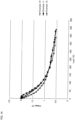
- the response speed of the sensor can be evaluated by measuring the frequency dependence of the photoelastic constant.
- the photoelastic constant decreases as the frequency increases.
- the photoelastic constant is small in the high frequency region, the response speed of the sensor slows.
- the photoelastic constant is constant with the frequency range of 0.1Hz to 100Hz even if the temperature is -10°C.
- the photoelastic polyurethane of the present invention is expected to have a quick response speed and a wide temperature range for use, and therefore as described later, it is suitably used for detection members and sensors, especially for a material for a pressure-sensitive sensor. Furthermore, such a detection member is, as described below, used suitably for a component of a robot.
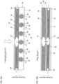
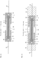
- the sensor 1 is formed into a bar shape (for example, cylindrical bar, elliptic cylindrical bar, prism, etc.) extending in one direction (right direction on the plane of paper in FIG. 1 ) and the other direction (left direction on the plane of paper in FIG. 1 ).
- the sensor 1 includes a resin member 2, a light generating unit 3, a light receiving unit 4, and a cover 5.
- the resin member 2 is disposed inside the sensor 1.
- the resin member 2 is formed into a bar shape (for example, cylindrical bar, elliptic cylindrical bar, prism, etc.) extending in longitudinal direction (that is, one side and the other side) of the sensor 1.
- the resin member 2 is made of the above-described photoelastic polyurethane resin.
- the resin member 2 is formed into a bar shape by, for example, a mold (casting mold) with a predetermined shape, or formed into a bar shape by cutting after removed from the mold.
- the light generating unit 3 is disposed at one end portion of the sensor 1.
- the light generating unit 3 includes a cap member 3A, a LED 3B as an example of the light generating member, and wiring 3C.
- the cap member 3A is formed into a generally cylindrical shape extending in longitudinal direction of the sensor 1.
- a depressed portion 3D is formed in the cap member 3A.
- the depressed portion 3D is depressed to one side from the other side end face of the cap member 3A.
- the one side end portion of the resin member 2 is fitted inside the depressed portion 3D.
- the LED 3B is embedded at the end face (inner face on one side) of the depressed portion 3D.
- the LED 3B is disposed to face one end face of the resin member 2. This allows the light of the LED 3B to enter one side end face of the resin member 2.
- the position of the LED 3B that is, the position facing the one side end face of the resin member 2, is an example of the first position.
- the wiring 3C is electrically connected to the LED 3B.
- the light receiving unit 4 includes a cap member 4A, a photodiode 4B as an example of the light receiving member, and wiring 4C.
- the cap member 4A is formed into a generally cylindrical shape extending in longitudinal direction of the sensor 1.
- a depressed portion 4D is formed in the cap member 4A.
- the depressed portion 4D is depressed to the other side from one side end face of the cap member 4A.
- the other side end portion of the resin member 2 is fitted inside the depressed portion 4D.
- the photodiode 4B is embedded at the end face (inner face on the other side) of the depressed portion 4D.
- the photodiode 4B is disposed to face the other side end face of the resin member 2. This allows the photodiode 4B to receive the light that has passed through the resin member 2 from one side to the other side.
- the position of the photodiode 4B that is, the position facing the other side end face of the resin member 2, is an example of the second position.
- the wiring 4C is electrically connected to the photodiode 4B.
- the cover 5 covers the resin member 2 between the light generating unit 3 and the light receiving unit 4.
- the cover 5 is formed into a generally cylindrical shape extending in longitudinal direction of the sensor 1.
- the resin member 2 is inserted inside the cover 5.
- the one side end face of the cover 5 is in contact with the cap member 3A of the light generating unit 3 at the peripheral portion of the depressed portion 3D.
- the other side end face of the cover 5 is in contact with the cap member 4A of the light receiving unit 4 at the peripheral portion of the depressed portion 4D.
- the cover 5 is composed, preferably, of resin with lower hardness than the resin member 2, for example, silicone resin, isoprene resin, butadiene resin, chloroprene resin, acrylic resin, and photoelastic polyurethane resin.
- the cover 5 can be colored, and can be transparent or semi-transparent.
- the sensor 1 can be used as a pressure-sensitive sensor.
- the senor 1 is placed on a flat support member S so that the cover 5 is in contact with the support member S.
- the sensor 1 is electrically connected to a control unit through the wiring 3C of the light generating unit 3 and the wiring 4C of the light receiving unit 4.
- the pressing member P is in contact with a center portion in the longitudinal direction of the sensor 1.
- the pressing member P is curved so that its center portion in direction connecting one side and the other side bulges downward.
- the pressure applied to the resin member 2 can be measured.
- the senor 1 may further include a cushioning material C.
- the cushioning material C is laminated on the resin member 2 so as to be disposed between the resin member 2 and the support member S.
- the cushioning material C is composed of a material softer than the resin member 2, for example, foam such as polyurethane sponge.
- the center portion in up-down direction of the resin member 2 can be flexed (curved) when the center portion in up-down direction of the resin member 2 is pressed with the pressing member P.
- More significant birefringence can be caused at the center portion in up-down direction of the resin member 2 in this manner.
- the senor 1 can have no cover 5.
- the pressing member P and the support member S are in direct contact with the resin member 2.
- the sensor 1 can be used, as shown in FIG. 6 and FIG. 7 , as a pressure-sensitive sensor of an autonomically drivable vacuuming robot 21 (an example of robot).
- the vacuuming robot 21 is formed into a generally disc shape having a thickness in up-down direction.
- the vacuuming robot 21 includes a main body 22, and a plurality of (6) sensors 1, and a bumper 23.
- the main body 22 is disposed at a center in radial direction of the vacuuming robot 21.
- the main body 22 is formed into a generally disc shape having a thickness in up-down direction.
- the main body 22 includes, in its inside, a control unit that controls autonomous driving, which is not shown, as an example of a processor, a motor, which is not shown, a suction device, which is not shown, for vacuuming dust, and a reservoir unit that accumulates the sucked dust.
- the main body 22 has at its bottom portion, wheels, and a cleaning brush for scraping out the dust.
- the plurality of sensors 1 are disposed in spaced apart relation from each other in circumferential direction at an outer side in radial direction of the main body 22.
- the sensors 1 are disposed, as shown in FIG. 7 , so that their longitudinal direction is along up-down direction.
- the sensor 1 is fixed, with flat support member S, at an outer peripheral face of the main body 22.
- the sensor 1 is electrically connected to the control unit in the main body 22 through the wiring 3C of the light generating unit 3, and the wiring 4C of the light receiving unit 4.
- the number of the sensor 1 is not particularly limited, and for example, the number is 3 to 10.
- the bumper 23 is disposed at an outer side in radial direction of the main body 22 so as to sandwich the sensor 1 between the main body 22 and the bumper 23.
- the bumper 23 is movable in a direction closer to the main body 22, and in a direction going away from the main body 22 in the radial direction of the main body 22.
- the bumper 23 includes a pressing member P.
- the pressing member P is disposed at an inner face of the bumper 23.
- the inner face in radial direction of the pressing member P has a center portion in up-down direction curved so as to bulge inward in radial direction.
- the pressing member P is in contact with the center portion in up-down direction of the sensor 1 at the center portion in up-down direction of an inner face in radial direction.
- the vacuuming robot 21 travels while cleaning the floor with the cleaning brush at the bottom portion by control from the control unit.
- the resin member 2 of the sensor 1 is not pressurized, or deformed, and therefore no birefringence is caused. Therefore, the light from the LED 3B of the sensor 1 hardly attenuate, and passes through the resin member 2 and received by the photodiode 4B.
- control unit of the vacuuming robot 21 determines that no collision with obstruction (room wall, etc.) is happening.
- the pressing member P of the bumper 23 presses the center portion in up-down direction of the sensor 1.
- the center portion in up-down direction of the resin member 2 of the sensor 1 is decompressed (deformed) between the pressing member P and the support member S, and causes birefringence.
- the cover 5 absorbs the pressure to the resin member 2 with the pressing member P, and deformation of the resin member 2 is suppressed. This prevents generation of birefringence to the resin member 2 due to small impact (for example, disturbance while running, etc.).
- control unit of the vacuuming robot 21 measures the pressure applied to the resin member 2 based on attenuation in quantity of light of received by the photodiode 4B.
- control unit of the vacuuming robot 21 determines, when a pressure, that is, a predetermined pressure to the resin member 2, applied to the resin member 2 is detected, that collision to obstruction occurred. Then, the vacuuming robot 21 changes its direction to avoid obstruction with control of the control unit.
- the vacuuming robot 21 cleans the floor in this manner so as to avoid the obstruction.
- the vacuuming robot 21 can also include a sensor 1 (ref: FIG. 3 ) including a cushioning material C, as shown in FIG. 8 .
- a pressure-sensitive mat 31 as a second embodiment of the detection member of the present invention is described.
- the members that are the same as the above-described first embodiment are given the same reference numerals, and descriptions thereof are omitted.
- a pressure-sensitive mat 31 includes, a sheet sensor 30 including a LED 36 as an example of the light generating member, and a rod sensor 38 including photodiode as an example of the light receiving member.
- the pressure-sensitive mat 31 is formed into a rectangular shape when viewed in plan view having a thickness in up-down direction.
- the pressure-sensitive mat 31 includes a first layer 32, a second layer 33, and a cover layer 34.
- the first layer 32 is disposed at an upper half of the pressure-sensitive mat 31.
- the first layer 32 includes a sheet sensor 30.
- the sheet sensor 30 includes a resin sheet 35, and a plurality of LEDs 36.
- the resin sheet 35 is composed of the above-described photoelastic polyurethane resin, and is formed into a sheet shape having a rectangular shape when viewed in plan view extending in both longitudinal direction (in a direction perpendicular to the thickness direction of the pressure-sensitive mat 31) and the width direction (direction perpendicular to both thickness direction and longitudinal direction of the pressure-sensitive mat 31) of the pressure-sensitive mat 31.
- the plurality of LEDs 36 include six LEDs 36 disposed at one end portion in longitudinal direction of the resin sheet 35, and six LEDs 36 disposed at the other end portion in longitudinal direction of the resin sheet 35.
- the six LEDs 36 at one end portion in longitudinal direction are disposed in parallel in width direction in spaced apart relation from each other.
- the six LEDs 36 at the other end portion in longitudinal direction are disposed in parallel in width direction in spaced apart relation from each other so as to coincide with the six LEDs 36 at one end portion longitudinal direction when projected in longitudinal direction. In this manner, the LED 36 allows the light to enter the end portion in longitudinal direction of the resin sheet 35.
- the position of the LED 36 that is, the end portion in longitudinal direction of the resin sheet 35, is an example of the first position.
- the LEDs 36 are, although not shown, electrically connected to the control unit as an example of the processor.
- the second layer 33 is disposed at a lower half of the pressure-sensitive mat 31 while making contact with the lower face of the first layer 32.
- the second layer 33 includes a cushioning material 37 and a plurality of (six) rod sensors 38.
- the cushioning material 37 is, similarly to the resin sheet 35, formed into a rectangular shape when viewed in plan view.
- the cushioning material 37 is composed of a material softer than the resin sheet 35, for example, foam such as polyurethane sponge.
- the length in longitudinal direction and the width direction of the cushioning material 37 are the same as the length in longitudinal direction and length in width direction of the resin sheet 35.
- the thickness of the cushioning material 37 is the length in up-down direction of the rod sensor 38 or more.
- the upper face of the cushioning material 37 is in contact with the lower face of the resin sheet 35.
- the plurality of (six) rod sensors 38 are embedded in the cushioning material 37, and are disposed in parallel in longitudinal direction of the pressure-sensitive mat 31 in spaced apart relation from each other.
- the rod sensor 38 has a generally cylindrical bar shape extending in width direction of the pressure-sensitive mat 31.
- the rod sensor 38 includes resin rods 39, two photodiodes 40, and a cover 41.
- the resin rods 39 are composed, similarly to the resin member 2 in the first embodiment, of the above-described photoelastic polyurethane resin, and is formed into a bar shape extending in width direction of the pressure-sensitive mat 31.
- the two photodiodes 40 are embedded in the resin rod 39, one each at both end portions in width direction.
- the photodiodes 4B are capable of receiving light that passed through the resin rod 39 from the inner side in width direction to the outside in width direction.
- the position of the photodiodes 4B is, that is, the end portion in width direction of the resin rod 39, is an example of the second position.
- the cover 41 is formed, similarly to the cover 5 in the first embodiment, into a generally cylindrical shape extending in longitudinal direction of the rod sensor 38, and covers the resin rod 39.
- the cover 41 is composed of a resin material that is transparent, and that has a refraction lower than that of the photoelastic polyurethane resin.
- the upper end portion of the cover 41 is in contact with the lower face of the resin sheet 35.
- the cover 41 has a refraction higher than the refraction of the resin sheet 35, the light that passes through the resin sheet 35 may not be transmitted easily to the resin rod 39 when the pressure-sensitive mat 31 is pressed.
- the cover 41 has a refraction that is the same level as the refraction of the resin sheet 35, a portion of light that passes through the resin sheet 35 may be transmitted to the resin rod 39 even when the pressure-sensitive mat 31 is not pressed.
- the cover layer 34 forms the outer skin portion of the pressure-sensitive mat 31.
- the cover layer 34 covers the first layer 32 and the second layer 33 altogether.
- the cover layer 34 is composed of, in view of texture, for example, fabric such as cotton and polyester.
- the resin sheet 35 of the sheet sensor 30 or the resin rod 39 of the rod sensor 38 are not pressed, and not deformed. Therefore, no birefringence is caused in the resin sheet 35 or the resin rod 39. In this manner, the light from the LED 36 of the sheet sensor 30 is not transmitted to the resin rod 39, and the photodiode 40 does not receive the light.
- control unit as an example of the processor of the pressure-sensitive mat 31 determines that the pressure-sensitive mat 31 is not pressed.
- the light from the LED 36 of the sheet sensor 30 scatters at the portion A1 where birefringence is caused in the resin sheet 35.
- the light scattered at the portion A1 is transmitted to the portion A2 where birefringence is caused in the resin rod 39.
- the light transmitted to the resin rod 39 is scattered at the portion A2.
- the light scattered at the portion A2 passes through the resin rod 39, and is received by the two photodiodes 40 at both ends of the resin rod 39.
- the light having higher intensity is detected at the portion near the pressed portion in the photodiode 40, and the light detected by the photodiode 40 gets weaker as the position goes far from the pressed portion.
- the control unit determines the position in longitudinal direction of the pressed portion from the position in longitudinal direction of the resin rod 39 having the photodiode 40 that received the light.
- the control unit determines the position in width direction of the pressed portion based on the difference in light intensities detected by the two photodiodes 40.
- the position in longitudinal direction and position in width direction of the pressed portion can be specified in this manner.
- control unit can measure the pressure applied to the pressure-sensitive mat 31 based on the light intensity detected by the two photodiodes 40.
- the pressure-sensitive mat 31 is suitable for use by, for example, setting at the floor in which a nursing bed is placed, and detecting if the care receiver is off the bed and on the floor, and for watching the care receiver.
- the pressure-sensitive mat 31 is used for an entrance mats, coming and going of people from the entrance can be detected, which makes it suitable for crime prevention.
- a plurality of rod sensors 38 can be used instead of the sheet sensor 30 of the first layer 32.
- the rod sensor 38 of the first layer 32 and the rod sensor 38 of the second layer 33 are placed on top of another like a grid.
- no cushioning material 37 is provided between the rod sensors 38.
- a sensor 50 as a third embodiment of the detection member of the present invention is described.
- the members that are the same as the above-described first embodiment are given the same reference numerals, and descriptions thereof are omitted.
- the senor 50 is configured as a bending sensor that detects bending of the resin member 2.
- the sensor 50 is configured as the same as the sensor 1 of the first embodiment, except that, as shown in FIG. 12 , the cap member 3A of the light generating unit 3 and the cap member 4A of the light receiving unit 4 includes a regulation unit 51 that regulates bending of the resin member 2.
- the regulation unit 51 of the light generating unit 3 is formed into a generally cylindrical shape extending from the other end portion of the cap member 3A to the other side.
- the regulation unit 51 of the light generating unit 3 covers the one end portion of the cover 5.
- the regulation unit 51 of the light generating unit 3 is formed from, for example, hard resin, and regulates bending of one end portion of the cover 5 and one end portion of the resin member 2.
- the regulation unit 51 of the light receiving unit 4 is formed into a generally cylindrical shape extending from one end portion of the cap member 4A to one side.
- the regulation unit 51 of the light receiving unit 4 covers the other end portion of the cover 5.
- the regulation unit 51 of the light receiving unit 4 is formed from, for example, hard resin, and regulates bending of the other end portion of the resin member 2 and the other end portion of the cover 5.
- the regulation unit 51 of the light receiving unit 4 is disposed to face the regulation unit 51 of the light generating unit 3 in spaced apart relation.
- bending portion B only the center portion in longitudinal direction of the resin member 2 (in the following, may be referred to as bending portion B.) is exposed from the cap member 3A of the light generating unit 3 and the cap member 4A of the light receiving unit 4, and is bendable.
- the arm 61 includes a first arm portion 62, a second arm portion 63, a joint portion 64, and a sensor 50.
- the first arm portion 62 configures one half of the arm 61, and is formed into a generally pillar shape extending in one side and the other side.
- the second arm portion 63 configures the other half of the arm 61, and is formed into a generally pillar shape extending in one side and the other side.
- the joint portion 64 is disposed between the first arm portion 62 and the second arm portion 63.
- the joint portion 64 connects the first arm portion 62 and the second arm portion 63 so that they are rotatable.
- the sensor 50 is fixed to the first arm portion 62 in the light generating unit 3, and is fixed to the second arm portion 63 in the light receiving unit 4 so that the bending portion B is disposed at the joint portion 64.
- the sensor 50 is bent at the bending portion B following the bending of the arm 61.
- the degree of bending angle at the arm 61 can be measured accurately.
- a semiconductor laser (wavelength 405 nm to 1064 nm), a fluorescent lamp, a halogen lamp, and a tungsten lamp may be used.
- LEDs are used as the light generating member, for example, red LED, white LED, infrared LED, green LED, and blue LED may be used.
- photo IC diode can also be used.
- an amplification circuit for photo current is embedded, and the photo current generated at the photodiode is amplified to 1000 times to several 1000 times, and outputted to the outside. It is preferable that when a general photodiode is used, a known amplification circuit is connected to the photodiode, and the photo current is amplified to about 1000 times to 10000 times.
- a detector other than the photodiode for example, a photoconductive detector such as CdS cell, and a thermosensitive light detector such as bolometer can be used.
- a linear polarizing plate can be placed between the photoelastic polyurethane resin and the light generating unit, and between the photoelastic polyurethane resin and the light receiving unit.
- the two linear polarizing plates are preferably set so that their plane of polarization coincide with each other.
- two circular polarizing plates can be set.
- two circular polarizing plates that are having the same rotational direction of the electric field vector are preferably used.
- a right rotation circular polarizing plate is set for the light generating unit side
- a right rotation circular polarizing plate is preferably set for the light receiving side. Examples
- the present invention is described in further detail in the following with reference to Examples and Comparative Examples, but the present invention is not limited to these Examples.
- the “parts” and “%” are based on mass unless otherwise specified.
- the specific numeral values such as the mixing ratio (content), physical property value, and parameter used in description below can be replaced with the corresponding mixing ratio (content), the physical property value, and parameter, that is, the upper limit value (numeral values defined with “or less”, “less than”) or the lower limit value (numeral values defined with "or more", “more than”) of the corresponding description used in the above-described "DESCRIPTION OF EMBODIMENTS".
- a glass-made flask was charged with PTG-650SN, PTG-1000, and an antioxidant in a blending amount shown in Table 1, and the mixture was dried under reduced pressure at 120°C for 2 hours. The temperature was decreased to 80°C, and the pressure was set back to normal pressure with nitrogen.
- the produced polyurethane composition was poured into a mold (30 cm ⁇ 10 cm ⁇ 2 mm), and curing was conducted at 50°C for 48 hours, thereby producing photoelastic polyurethane resin having a sheet shape and having a thickness of 2 mm.
- a silicone tube (external diameter 10 mm, internal diameter 7 mm, length 60 cm) was charged with the produced polyurethane composition, one end was pinched with a pinchcock, hung in an oven at 50°C for 48 hours. Curing was conducted, thereby producing photoelastic polyurethane resin having a bar shape and a diameter of 7 mm.
- a glass-made flask was charged with PTG-650SN, PTG-1000, and an antioxidant in a blending amount shown in Table 1, and the mixture was dried under reduced pressure at 120°C for 2 hours. The temperature was decreased to 80°C, and the pressure was set back to normal pressure with nitrogen.
- the produced polyurethane composition was cured in the same manner as in Example 1, thereby producing photoelastic polyurethane resin having a sheet shape and a thickness of 2 mm and photoelastic polyurethane resin having a bar shape and a diameter of 7 mm.
- a glass-made flask was charged with PTG-1000 and an antioxidant in a blending amount shown in Table 1, and the mixture was dried under reduced pressure at 120°C for 2 hours. The temperature was decreased to 80°C, and the pressure was set back to normal pressure with nitrogen.
- the produced polyurethane composition was cured in the same manner as in Example 1, thereby producing photoelastic polyurethane resin having a sheet shape and a thickness of 2 mm, and photoelastic polyurethane resin having a bar shape and a diameter of 7 mm.
- a glass-made flask was charged with PTG-1000 and an antioxidant in a blending amount shown in Table 2, and the mixture was dried under reduced pressure at 120°C for 2 hours. The temperature was decreased to 80°C, and the pressure was set back to normal pressure with nitrogen.
- the produced polyurethane composition was cured in the same manner as in Example 1, thereby producing photoelastic polyurethane resin having a sheet shape and a thickness of 2 mm, and photoelastic polyurethane resin having a bar shape and a diameter of 7 mm.
- Photoelastic polyurethane resin having a sheet shape and having a thickness of 2mm and photoelastic polyurethane resin having a bar shape and a diameter of 7 mm were produced in the same manner as in Example 4, except that the materials were blended in a blending amount shown in Table 2.
- a glass-made flask was charged with PTG-1000 and an antioxidant in a blending amount shown in Table 2, and the mixture was dried under reduced pressure at 120°C for 2 hours. The temperature was decreased to 80°C, and the pressure was set back to normal pressure with nitrogen.
- the produced polyurethane composition was cured in the same manner as in Example 1, thereby producing photoelastic polyurethane resin having a sheet shape and having a thickness of 2 mm, and photoelastic polyurethane resin having a bar shape and a diameter of 7 mm.
- Photoelastic polyurethane resin having a sheet shape and having a thickness of 2 mm and photoelastic polyurethane resin having a bar shape and a diameter of 7 mm were produced in the same manner as in Example 5, except that the materials were blended in a blending amount shown in Table 2.
- the plasticizer was blended in the produced polyurethane composition.
- Photoelastic polyurethane resin having a sheet shape and having a thickness of 2 mm and photoelastic polyurethane resin having a bar shape and a diameter of 7 mm were produced in the same manner as in Example 5, except that the materials were blended in a blending amount shown in Table 3.
- the plasticizer was blended in the produced polyurethane composition.
- a glass-made flask was charged with PTG-650SN and an antioxidant in a blending amount shown in Table 1, the mixture was dried under reduced pressure at 120°C for 2 hours, and the pressure was set back to normal pressure with nitrogen.
- the produced polyurethane composition was cured in the same manner as in Example 1, thereby producing photoelastic polyurethane resin having a sheet shape and having a thickness of 2 mm and photoelastic polyurethane resin having a bar shape and a diameter of 7 mm.
- a sample piece was cut into a strip of a length of 2.5 cm, a width of 5.0 mm, and a thickness of 2.0 mm.
- the sample was measured using a dynamic viscoelasticity measuring apparatus (VES-F-III, VISCO-ELASTIC SPECTROMETER, manufactured by Iwamoto Seisakusho Co., Ltd.), with a temperature distribution mode at a temperature increase rate of 5°C/min, a frequency of 10Hz, an amplitude of ⁇ 0.01 mm, to obtain a storage modulus (E'), loss modulus (E"), and loss tangent (tan ⁇ ).
- the temperature of the peak value of the loss tangent (tan ⁇ ) of the obtained data was defined as the glass transition temperature.
- Table 1, Table 2, and Table 3 show the storage modulus (E'), loss modulus (E"), loss tangent (tan ⁇ ) and glass transition temperature of Examples and Comparative Examples.
- Example 1 The frequency dependence of photoelastic constant in Examples 1 to 3 and Comparative Example 1 was measured with the measurement frequency changed between 0.1 to 100Hz.
- Table 1 shows the ratio of the photoelastic constant at a frequency of 100Hz setting the value at 0.1Hz to 100.
- FIG. 14 shows the frequency dependence of photoelastic constant at -10°C of Examples 1 to 3 and Comparative Example 1.
- the pressure-sensitive sensor was made using the bar shape photoelastic polyurethane resin of Examples 1, 4 to 6, 8, and 10 to 15, as shown in FIG. 1 .
- the resin member 2 composed of the bar shape photoelastic polyurethane resin is a bar having a diameter of 7 mm and a length of 7 cm, and the silicone tube is removed.
- the LED 3B is a red LED.
- the photodiode 4B is photo IC diode.
- the LED 3B is, as shown in the imaginary line in FIG. 2 , connected to a series circuit 70 having a battery 71 (direct current 3V) and a variable resistor 72.
- a voltmeter 73 is connected to the series circuit 70. Then, the variable resistor 72 was adjusted so that the voltage of the voltmeter 73 was 2V with the LED 3B turned on.
- the pressure sensor was disposed, as shown in FIG. 2 , between the support member S and the pressing member P. Then, a load is applied to the pressing member P, and the load and the voltage measured by the voltmeter 73 were recorded with every drop of the pressing member P by 0.2 mm, until the pressing member P was dropped to 4 mm. The measurement results are shown in FIG. 15 to FIG. 17 .
- FIG. 18 shows the measurement results setting the vertical axis as the inverse number of the voltage.
- Table 4 shows the voltage (V 300 ) and sensitivity with the load of 300N of the pressure-sensitive sensor in which the photoelastic polyurethane resin of Examples 1, 4, 6, and 10 to 15 was used.
- the sensitivity is a value deducting the voltage with the load of 300N from the voltage with no load (that is, 2V), and with higher sensitivity, a small load can be measured with more accuracy.
- Table 4 shows the load and the voltage with the displacement amount (length of descending of the pressing member P) of 5 mm.
- the maximum load that these pressure-sensitive sensors can measure was the voltage with the displacement amount of 5 mm.
- Table 4 shows the voltage immediately after decompression (restoring the pressing member P to the original position) and the voltage after 10 minutes from decompression, after measuring the voltage with the displacement amount of 5 mm.
- Example 1 Example 10
- Example 11 Example 12
- Example 4 Example 6
- Example 13 Example 14
- Aromatic ring concentration (mass%) 15.5 15.2 14.5 14.0 13.8 13.4 12.4 10.8 10.0
- Table 4 shows that when the photoelastic constant is higher than 6000 ⁇ 10 -12 Pa -1 , sensitivity tends to be low, and meanwhile, when the photoelastic constant is lower than 3500 ⁇ 10 -12 Pa -1 , the maximum load that allows for measurement, that is, the load with the displacement amount of 5 mm becomes small.
- the bending sensor was made using the photoelastic polyurethane resin obtained in Example 1, as shown in FIG. 12 .
- the sensor 50 had a bending portion B with a length of 30 mm.
- the sensor 50 is set, as shown in FIG. 13 , on the arm 61, and the angle and the voltage were recorded while changing continuously the angle of the arm 61 from 0°(horizontal) to 90°(vertical).
- the photoelastic polyurethane resin of the present invention can be used as a detection member such as a pressure-sensitive sensor and a bending sensor in robots and devices in various industrial fields.
Landscapes
- Chemical & Material Sciences (AREA)
- Health & Medical Sciences (AREA)
- Chemical Kinetics & Catalysis (AREA)
- Medicinal Chemistry (AREA)
- Polymers & Plastics (AREA)
- Organic Chemistry (AREA)
- Physics & Mathematics (AREA)
- General Physics & Mathematics (AREA)
- Polyurethanes Or Polyureas (AREA)
Description
- The present invention relates to photoelastic polyurethane resin, a detection member, a robot, and a method for producing photoelastic polyurethane resin. In particular, the present invention relates to photoelastic polyurethane resin, a detection member including the photoelastic polyurethane resin, a robot including the detection member, and a method for producing photoelastic polyurethane resin.
- Conventionally, use of polyurethane resin having photoelasticity as a sensor such as a pressure-sensitive sensor has been proposed.
- For example,
Patent Document 1 below has proposed a touch panel including a polyurethane molded article for a pressure-sensitive sensor made of polyurethane resin, and a light generating unit and a light receiving unit that are provided so as to sandwich the polyurethane molded article for a pressure-sensitive sensor (see below). - The touch panel detects birefringence caused inside the polyurethane molded article for a pressure-sensitive sensor when a pressure is applied by, for example, a finger based on attenuation of light that was allowed to exit from the light generating unit and enters the light receiving unit.
- [Patent Document 1]
Japanese unexamined patent publication 2012-193293
US 2006/152378 A1 concerns a bed occupant monitoring system comprising a pressure sensitive member attached to a support member for supporting a bed occupant, the pressure sensitive member comprising a plurality of pressure sensors. Each of the pressure sensors is configured to provide a reflected wave energy pressure signal by reflecting incident wave energy with an intensity which varies with a pressure applied to the sensor. A pair of fibres are coupled to each pressure sensor, each pair of fibres comprising an input fibre and an output fibre. The fibres are coupled to interface electronics comprising a wave energy source coupled to the input fibre of each of the pairs of fibres for providing the applied light energy, and, a wave energy detector coupled to the output fibre of each of the pairs of fibres for converting the scattered light energy into an electrical signal.
JP 2012/193293 A
EP 2 558 832 A1
US 2013/333094 A1 describes appendage mountable electronic systems and related methods for covering and conforming to an appendage surface. A flexible or stretchable substrate has an inner surface for receiving an appendage, including an appendage having a curved surface, and an opposed outer surface that is accessible to external surfaces. A stretchable or flexible electronic device is supported by the substrate inner and/or outer surface, depending on the application of interest. The electronic device in combination with the substrate provides a net bending stiffness to facilitate conformal contact between the inner surface and a surface of the appendage provided within the enclosure. In an aspect, the system is capable of surface flipping without adversely impacting electronic device functionality, such as electronic devices comprising arrays of sensors, actuators, or both sensors and actuators. - However, with the polyurethane resin described in the above-described
Patent Document 1, the birefringence is not generated right after the pressure application, and when the polyurethane resin is used as a sensor, responsiveness may be poor. - In particular, responsiveness tends to be reduced in a cold district.
- Thus, an object of the present invention is to provide photoelastic polyurethane resin that can provide a detection member having excellent responsiveness, in particular excellent responsiveness in a cold district, a detection member including the photoelastic polyurethane resin, a robot including the detection member, and a method for producing photoelastic polyurethane resin.
- In a first aspect, the present invention is directed to a photoelastic polyurethane resin comprising
- a reaction product of
- an aromatic ring-containing polyisocyanate,
- a polytetramethylene ether polyol having an average hydroxyl number of 20 to 500 mgKOH/g and
- a low molecular weight triol having an average hydroxyl number of more than 500 mgKOH/g,
- wherein the mass ratio of the aromatic ring derived from the aromatic ring-containing polyisocyanate in the polyurethane resin composition is 10 mass% or more and 16 mass% or less, relative to the polyurethane resin composition; and
- wherein the photoelastic polyurethane resin has
- a Young's modulus at 25°C of 2 to 5MPa,
- a photoelastic constant at 25°C of 1000 × 10-12 Pa-1 to 100000 × 10-12Pa-1, and a glass transition temperature of -60°C to -21°C;
- wherein Young's modulus and the photoelectric constant are determined according to the following method described in this specification.
- A second aspect of the invention relates to a detection member comprising:
- the photoelastic polyurethane resin of the present invention described above,
- a light generating member disposed at a first position at which light can be allowed to enter the photoelastic polyurethane resin, and
- a light receiving member disposed at a second position that is different from the first position and at which the light that is allowed to exit from the light generating member and passed through the photoelastic polyurethane resin can be received.
- A third aspect of the present invention relates to a robot comprising the above-described detection member.
- A fourth aspect of the present invention relates to a method for producing the above-described photoelastic polyurethane resin according to
claim 11. - In the photoelastic polyurethane resin of the present invention, the Young's modulus at 25°C is adjusted to 2 to 5MPa, the photoelastic constant at 25°C is adjusted to 1000 × 10-12Pa-1 to 100000 × 10-12Pa-1, and the glass transition temperature is adjusted to -60°C to -21°C.
- Therefore, a detection member having excellent responsiveness, especially at a cold district can be produced.
- The detection member of the present invention includes the above-described photoelastic polyurethane resin, and therefore responsiveness, responsiveness at especially in a cold district is excellent.
- The robot of the present invention includes the above-described detection member, and therefore can be operated with good responsiveness even in a cold district.
-
-
FIG. 1 is a cross-sectional view illustrating a sensor as a first embodiment of the detection member of the present invention. -
FIG. 2 is a figure illustrating pressure application on the sensor shown inFIG. 1 . -
FIG. 3 is a figure illustrating an embodiment of a modified example in which the sensor shown inFIG. 1 includes a cushioning material. -
FIG. 4 is a figure illustrating an embodiment of a modified example in which the sensor shown inFIG. 1 includes no cover. -
FIG. 5 is a figure illustrating pressure application on the sensor shown inFIG. 4 . -
FIG. 6 is a schematic diagram illustrating a robot including the sensor shown inFIG. 1 . -
FIG. 7 is a figure illustrating contacts between the sensor shown inFIG. 6 and a pressing member of a bumper. -
FIG. 8 is a figure illustrating an embodiment of a modified example in which a cushioning material is included for contact between the sensor shown inFIG. 7 and the pressing member of a bumper. -
FIG. 9 is a perspective view illustrating a pressure-sensitive mat as a second embodiment of the detection member of the present invention. -
FIG. 10A is a longitudinal cross section of the pressure-sensitive mat shown inFIG. 9 .FIG. 10B is a widthwise cross section of the pressure-sensitive mat shown inFIG. 9 . -
FIG. 11 is a figure illustrating a modified example of the pressure-sensitive mat. -
FIG. 12 is a perspective view illustrating a sensor as a third embodiment of the detection member of the present invention. -
FIG. 13 is a figure illustrating a state in which the sensor shown inFIG. 12 is placed on an arm. -
FIG. 14 is a graph illustrating relationship between the photoelastic constant at -10°C and the frequency. -
FIG. 15 is a graph illustrating relationship between the load and the voltage when the photoelastic polyurethane resin of Examples 1, 4 to 6, and 8 is used for the pressure-sensitive sensor. -
FIG. 16 is a graph illustrating relationship between the load and the voltage when the photoelastic polyurethane resin of Examples 10 to 12 is used for the pressure-sensitive sensor. -
FIG. 17 is a graph illustrating relationship between the load and the voltage when the photoelastic polyurethane resin of Examples 13 to 15 is used for the pressure-sensitive sensor. -
FIG. 18 is a graph illustrating relationship between the load and the inverse number of the voltage when the photoelastic polyurethane resin is used for the pressure-sensitive sensor. -
FIG. 19 is a graph illustrating relationship between the angle and the voltage when the photoelastic polyurethane resin is used for an angle sensor. - The photoelastic polyurethane resin of the present invention can be produced by allowing a polyurethane resin composition containing a polyisocyanate component and an active hydrogen group-containing component to react and cure.
- The polyisocyanate component contains, as an essential component, aromatic ring-containing polyisocyanate. The aromatic ring-containing polyisocyanate contains a 1,4-phenylene group (where a portion of the hydrogen atoms in the 1,4-phenylene group can be replaced with a methyl group and/or a methoxy group.) and/or a 1,5-naphthylene group.
- Examples of the aromatic ring-containing polyisocyanate containing a 1,4-phenylene group include benzene ring-containing polyisocyanates (to be specific, benzene ring-containing diisocyanates) such as 4,4'-diphenylmethane diisocyanate (4,4'-MDI), polymer of 4,4'-diphenylmethane diisocyanates (carbodiimide modified MDI, uretonimine modified MDI, acyl urea modified MDI, etc.), 2,4'-diphenylmethane diisocyanate (2,4'-MDI), 3,3'-dimethylbiphenyl-4,4'-diisocyanate (TODI), 3,3'-dimethoxybiphenyl-4,4'-diisocyanate, p-phenylenediisocyanate, 4,4'-diphenyl diisocyanate, 4,4'-diphenylether diisocyanate, 2,4-tolylene diisocyanate (2,4-TDI), and 1,4-xylylene diisocyanate (1,4-XDI).
- Examples of the aromatic ring-containing polyisocyanate containing a 1,5-naphthylene group include naphthalene ring-containing polyisocyanate (to be specific, naphthalene ring-containing diisocyanate) such as 1,5-naphthalene diisocyanate (1,5-NDI).
- Of the aromatic ring-containing polyisocyanate containing a 1,4-phenylene group and/or a 1,5-naphthylene group, preferably, 4,4'-diphenylmethane diisocyanate (4,4'-MDI), 3,3'-dimethylbiphenyl-4,4'-diisocyanate (TODI), and 1,5-naphthalene diisocyanate (1,5-NDI) are used.
- The polyisocyanate component can be used singly, or can be used in combination of two or more. Preferably, 4,4'-MDI and TODI are used in combination.
- The polyisocyanate component can contain other polyisocyanate, i.e., polyisocyanate other than the aromatic ring-containing polyisocyanate, as an optional component.
- Examples of the other polyisocyanate include aromatic polyisocyanates (excluding the above-described aromatic ring-containing polyisocyanate), araliphatic polyisocyanates (excluding the above-described aromatic ring-containing polyisocyanate), alicyclic polyisocyanates, and aliphatic polyisocyanates.
- Examples of the aromatic polyisocyanate include aromatic diisocyanates such as 2,2'-MDI, 2,6-TDI, m-phenylenediisocyanate, and 2,6-NDI.
- Examples of the araliphatic polyisocyanates include araliphatic diisocyanates such as 1,3-xylylene diisocyanate (1,3-XDI), and tetramethylxylylene diisocyanate (TMXDI).
- Examples of the alicyclic polyisocyanates include alicyclic diisocyanates such as 3-isocyanatomethyl-3,5,5-trimethylcyclohexyl isocyanate (isophorone diisocyanate, IPDI), 4,4'-,2,4'-or 2,2'-dicyclohexylmethanediisocyanate or a mixture thereof (H12MDI), 1,3-bis(isocyanatomethyl) cyclohexane (hydrogenated xylylene diisocyanate, H6XDI), 2,5-or 2,6-bis(isocyanatomethyl) norbornane or a mixture thereof (NBDI), 1,3-cyclopentanediisocyanate, 1,4- or 1,3-cyclohexanediisocyanate or a mixture thereof, methyl-2,4-cyclohexanediisocyanate, and methyl-2,6-cyclohexanediisocyanate.
- Examples of the aliphatic polyisocyanate include aliphatic diisocyanates such as trimethylenediisocyanate, tetramethylenediisocyanate (TMDI), pentamethylenediisocyanate (PDI), hexamethylenediisocyanate (HDI), 1,2-,2,3- or 1,3-butylenediisocyanate, and 2,4,4- or 2,2,4-trimethylhexamethylenediisocyanate.
- In the polyisocyanate component, the aromatic ring-containing polyisocyanate containing 1,4-phenylene group and/or 1,5-naphthylene group is blended in an amount of, relative to a total amount of the polyisocyanate component, for example, 30 mass% or more, more preferably 50 mass% or more, particularly preferably 90 mass% or more.
- The polyisocyanate component has an aromatic ring concentration of, relative to the polyurethane resin composition, 10 mass% or more, preferably 12 mass% or more, and 16 mass% or less.
- When the polyisocyanate component has an aromatic ring concentration of the above-described lower limit or more, excellent photoelasticity can be obtained.
- When the polyisocyanate component has an aromatic ring concentration of the above-described upper limit or less, excellent photoelasticity can be obtained.
- The aromatic ring concentration of the polyisocyanate component is the mass ratio of the aromatic ring derived from the polyisocyanate component in the polyurethane resin composition, and does not include the aromatic ring derived from the cyano compound to be described later.
- The aromatic ring concentration is calculated, when the polyisocyanate component contains 1,4-phenylene group, by setting the molecular weight of the polyisocyanate to 78 (g/mol), and when the polyisocyanate component contains 1,5-naphthylene group, by setting the molecular weight of the polyisocyanate to 128 (g/mol).
- The active hydrogen group-containing component is a compound having an active hydrogen group (for example, hydroxyl group, amino group, etc.). According to the present invention, the active hydrogen group-containing component comprises a polytetramethylene ether polyol having an average hydroxyl number of 20 to 500 mgKOH/g and a low molecular weight triol having an average hydroxyl number of more than 500 mgKOH/g.
- The low-molecular-weight triol has an average hydroxyl number (described later) of more than 500 mgKOH/g, and a molecular weight of 40 or more and less than 337. Examples of the triol (trihydric alcohol) include aliphatic triols having 3 to 6 carbon atoms including glycerin, 2-methyl-2-hydroxymethyl-1,3-propanediol, 2,4-dihydroxy-3-hydroxymethylpentane, 1,2,6-hexanetriol, trimethylolpropane, and 2,2-bis(hydroxymethyl)-3-butanol, and other aliphatic triols (having 7 to 20 carbon atoms).
- These low-molecular-weight polyols can be used singly, or can be used in combination of two or more.
- Examples of the polytetramethylene ether polyol include a ring-opening polymerized product produced by cationic polymerization of tetrahydrofuran; noncrystalline polytetramethylene ether glycol produced by coplymerizing the above-described diol with a polymerization unit of tetrahydrofuran; and noncrystalline polytetramethylene ether glycol produced by coplymerizing ethylene oxide, propyleneoxide, epichlorohydrin and/or benzylglycidyl ether with a polymerization unit of tetrahydrofuran.
- The polytetramethylene ether polyol is a high-molecular weight polyol and has an average hydroxyl number of 20 to 500 mgKOH/g, preferably 80 to 300 mgKOH/g, more preferably 100 to 250 mgKOH/g.
- The hydroxyl number (unit: mgKOH/g) of the high-molecular weight polyol can be determined by acetylation or phthalation accordance to method A or method B of JIS K 1557-1.
- The average hydroxyl number (unit: mgKOH/g) of the high-molecular weight polyol is the same as the hydroxyl number of the high-molecular weight polyol when the high-molecular weight polyol is used singly. Meanwhile, the average hydroxyl number of the high-molecular weight polyol is their average value when the high-molecular weight polyol is used in combination.
- When the average hydroxyl number of the high-molecular weight polyol is more than the range described above, the photoelastic polyurethane resin may have an excessively high Young's modulus, and the desired photoelastic constant may not be obtained. Meanwhile, when the average hydroxyl number is less than the range described above, the glass transition temperature is excessively low, and processability and scratch resistance may be reduced.
- The high-molecular weight polyol has an average functionality of, for example, 1.9 to 3, preferably 1.9 to 2.5, more preferably 2.0 to 2.2.
- The functionality of the high-molecular weight polyol is a number of the hydroxyl group of the high-molecular weight polyol. To be specific, it is the number of active hydroxyl groups per one molecule.
- The average functionality of the high-molecular weight polyol is an average value of the active hydroxyl group per one molecule of the high-molecular weight polyol. That is, when high-molecular weight polyols having different functionalities are mixed (used in combination), the numeral value showing the ratio of the number of the active hydroxyl group of the mixture relative to the number of the molecules of the mixture of the high-molecular weight polyol is the average functionality of the high-molecular weight polyol.
- The average functionality of the high-molecular weight polyol can also be determined from formula (B) below:
The average functionality=total of (functionality if each high-molecular weight polyol × equivalent number)/total of equivalent number of high-molecular weight polyols - The number average molecular weight can be determined from formula (C) below:
The number average molecular weight = 56100 × average functionality/average hydroxyl number - For the high-molecular weight polyol, polytetramethylene ether polyol is used.
- The polytetramethylene ether glycol preferably has an average hydroxyl number of 100 to 250 mgKOH/g, more preferably 100 to 220 mgKOH/g. When the polytetramethylene ether glycol has an average hydroxyl number within the above-described range, a high photoelasticity and high rigidity can be achieved both.
- These high-molecular weight polyols can be used singly, or can be used in combination of two or more.
- The polyol contains the above-described low-molecular-weight triol, in addition to the above-described high-molecular weight polytetramethylene ether polyol.
- When the polyol contains the low-molecular-weight triol, the average hydroxyl number of the polyol increases, and to the extent of the increase, to adjust the isocyanate index (described later) to a desired value, a large amount of the above-described polyisocyanate component (preferably, aromatic ring-containing polyisocyanate) can be blended in the polyurethane resin composition. Therefore, the photoelastic constant of the photoelastic polyurethane resin can be increased.
- For the low-molecular-weight triol, a triol having 3 to 10 carbon atoms is used.
- Examples of the triol having 3 to 10 carbon atoms include triols such as aliphatic triol having 3 to 6 carbon atoms including glycerin, 2-methyl-2-hydroxymethyl-1,3-propanediol, 2,4-dihydroxy-3-hydroxymethylpentane, 1,2,6-hexanetriol, trimethylolpropane, and 2,2-bis(hydroxymethyl)-3-butanol, and other aliphatic triols (having 7 to 10 carbon atoms).
- The low-molecular-weight polyol can be used singly, or can be used in combination of two or more.
- To be specific, a triol having 3 to 10 carbon atoms can be used singly, or a triol having 3 to 10 carbon atoms and a diol having 2 to 10 carbon atoms can be used in combination.
- The low-molecular-weight polyol is blended in an amount of, relative to 100 parts by mass of the high-molecular weight polyol, for example, 0.1 to 30 parts by mass, preferably 0.5 to 25 parts by mass.
- When the triol having 3 to 10 carbon atoms is used singly, for example, 10 parts by mass or less, preferably 9 parts by mass or less, more preferably 0.5 to 6 parts by mass of the triol having 3 to 10 carbon atoms is blended relative to 100 parts by mass of the high-molecular weight polyol.
- When the triol having 3 to 10 carbon atoms is blended in more than the above-described range, the photoelastic polyurethane resin becomes non-transparent, light may not pass the photoelastic polyurethane resin, and the Young's modulus of the photoelastic polyurethane resin may become excessively high.
- When the triol having 3 to 10 carbon atoms and the diol having 2 to 10 carbon atoms are used in combination, the triol having 3 to 10 carbon atoms is blended in an amount of, relative to 100 parts by mass of the high-molecular weight polyol, for example, 0.5 to 10 parts by mass, preferably 0.6 to 6 parts by mass, and the diol having 2 to 10 carbon atoms is blended in an amount of, relative to 100 parts by mass of the high-molecular weight polyol, for example, 25 parts by mass or less, preferably 0.1 to 10 parts by mass. When the triol having 3 to 10 carbon atoms and the diol having 2 to 10 carbon atoms are blended within the above-described range, high photoelasticity and high rigidity can be achieved both.
- When the triol having 3 to 10 carbon atoms and the diol having 2 to 10 carbon atoms are used in combination, they are blended in total of, relative to 100 parts by mass of the high-molecular weight polyol, for example, 0.1 to 30 parts by mass, preferably 0.5 to 25 parts by mass, more preferably 0.7 to 6 parts by mass.
- When the total amount of the triol and the diol is less than the above-described range, the Young's modulus may be excessively reduced, moldability and scratch resistance may be reduced, and the photoelastic constant may be reduced. When the total amount of the triol and the diol is more than the above-described range, the Young's modulus may be excessively high.
- The active hydrogen group-containing component is blended so that the high-molecular weight polyol in the active hydrogen group-containing component relative to 100 parts by mass of the polyisocyanate component is, for example, 120 to 400 parts by mass, preferably 125 to 333 parts by mass.
- In other words, the polyisocyanate component content relative to 100 parts by mass of the high-molecular weight polyol is, for example, 25 to 85 parts by mass, preferably 30 to 80 parts by mass. When the polyisocyanate component content is within the above-described range, high rigidity can be achieved.
- When the polyisocyanate component content is more than the above-described range, the Young's modulus is excessively high, and the desired photoelastic constant may not be achieved in the photoelastic polyurethane resin.
- When the polyisocyanate component content is less than the above-described range, the desired photoelastic constant may not be achieved in the photoelastic polyurethane resin.
- The polyurethane resin composition of the present invention can contain a plasticizer.
- The plasticizer is blended in the polyurethane resin composition as necessary to reduce the glass transition temperature of the photoelastic polyurethane resin, and examples thereof include a cyano compound, phthalic acid ester (for example, phthalic acid di-2-ethylhexyl, phthalic acid diisononyl (DINP)), adipic acid ester (for example, adipic acid dioctyl), sebacic acid ester (for example, sebacic acid dioctyl), phosphoric acid triglycidyl, acetylcitric acid tributyl, epoxidized soybean oil, trimellitic acidtrioctyl, alkylbenzene, alkylbiphenyl (for example, 4-pentylbiphenyl), chlorinated paraffin, a high boiling point solvent, ion liquid (for example, 1-ethyl-2,3-dimethylimidazolium bis(trifluoromethanesulfonyl) imide), and a polyester plasticizer. Preferably, a cyano compound is used.
- When the cyano compound is blended in the polyurethane resin composition, the Young's modulus of the molded article can be reduced, and with the reduced Young's modulus, processability of the photoelastic polyurethane resin can be improved, and the photoelastic constant can also be increased.
- The cyano compound has, for example, 14 to 24 carbon atoms, and a 4-cyanophenyl group (where a portion of hydrogen atoms in 4-cyanophenyl group may be replaced with fluorine atoms).
- When the cyano compound has the 4-cyanophenyl group, the photoelastic constant can be increased even more.
- In the 4-cyanophenyl group, for example, the hydrogen atoms at
positions 2 to 6 are replaced with the fluorine atoms, preferably, the hydrogen atom atposition 2 is replaced with the fluorine atom. - Examples of the cyano compound include, to be specific, a biphenyl compound represented by formula (1) below:


- (where R1 is an alkyl group having 1 to 11 carbon atoms, a 4-alkylphenyl group having 7 to 11 carbon atoms, or a 4-alkylcyclohexyl group having 7 to 11 carbon atoms),
an ether compound represented by formula (2) below,
- (where R2 represents an alkyl group having 1 to 11 carbon atoms),
- a cyclohexyl compound represented by formula (3) below,

- (R3 represents an alkyl group having 1 to 11 carbon atoms, or an alkenyl group having 5 to 11 carbon atoms), and
- a phenyl ester compound represented by formula (4) below,

- (R4 represents a hydrogen atom or an alkyl group having 1 to 10 carbon atoms).
- In the above-described formula (1), examples of the alkyl group having 1 to 11 carbon atoms represented by R1 include a straight chain or branched alkyl group such as methyl, ethyl, propyl, isopropyl, butyl, isobutyl, tert-butyl, pentyl, isopentyl, tert-pentyl, hexyl, heptyl, octyl, nonyl, isononyl, decyl, and dodecyl. Preferably, an alkyl group having 2 to 7 carbon atoms is used.
- In the above-described formula (1), examples of the 4-alkylphenyl group having 7 to 11 carbon atoms represented by R1 include a 4-alkylphenyl group having a straight chain or branched alkyl moiety with 1 to 5 carbon atoms such as 4-methylphenyl, 4-ethylphenyl, 4-propylphenyl, 4-isopropylphenyl, 4-pentylphenyl, 4-isopentylphenyl, and 4-tertpentylphenyl. Preferably, a 4-alkylphenyl group having 9 to 11 carbon atoms with an alkyl moiety with 3 to 5 carbon atoms is used.
- Examples of the 4-alkylcyclohexyl group having 7 to 11 carbon atoms include a 4-alkylcyclohexyl group having a straight chain or branched alkyl moiety with 1 to 5 carbon atoms such as 4-methylcyclohexyl, 4-ethylcyclohexyl, 4-propylcyclohexyl, 4-isopropylcyclohexyl, 4-pentylcyclohexyl, 4-isopentylcyclohexyl, and 4-tertpentylcyclohexyl. Preferably, a 4-alkylcyclohexyl group having 9 to 11 carbon atoms with an alkyl moiety having 3 to 5 carbon atoms is used.
- For R1 represented by the above-described formula (1), preferably an alkyl group having 1 to 11 carbon atoms, and a 4-alkylcyclohexyl group having 7 to 11 carbon atoms are used.
- For the biphenyl compound represented by the above-described formula (1), to be specific, 4-cyano-4'-methylbiphenyl, 4-cyano-4'-pentylbiphenyl, and 4-cyano-4'-(4-pentylcyclohexyl) biphenyl are used.
- In the above-described formula (2), examples of the alkyl group having 1 to 11 carbon atoms represented by R2 include the alkyl groups given as examples of alkyl group having 1 to 11 carbon atoms represented by R1 in the above-described formula (1).
- Examples of the ether compound represented by the above-described formula (2) include, to be specific, 4-cyano-4'-pentyloxybiphenyl.
- In the above-described formula (3), examples of the alkyl group having 1 to 11 carbon atoms represented by R3 include the alkyl group having 1 to 11 carbon atoms represented by R1 in the above-described formula (1).
- In the above-described formula (3), examples of the alkenyl group having 5 to 11 carbon atoms represented by R3 include pentenyl, hexenyl, heptenyl, octenyl, nonenyl, decynyl, and dodecenyl.
- In the above-described formula (3), for R3, preferably, an alkyl group having 1 to 11 carbon atoms is used.
- Examples of the cyclohexyl compound represented by the above-described formula (3) include, to be specific, 4-(4-pentylcyclohexyl) benzonitrile, 4-((3-pentenyl)-4-cyclohexyl) benzonitrile, and 2-fluoro-4-(4-pentylcyclohexyl) benzonitrile.
- In the above-described formula (4), examples of the alkyl group having 1 to 10 carbon atoms represented by R4 include, of the alkyl groups given as examples of the alkyl group having 1 to 11 carbon atoms represented by R1 in the above-described formula (1), the alkyl groups of the alkyl group having 1 to 10 carbon atoms are used.
- Examples of the phenylester compound represented by the above-described formula (4) include 4-propylbenzoic acid 4-cyanophenyl, 4-heptylbenzoic acid 4-cyanophenyl, and 4-pentylbenzoic acid 4-cyano-3,5-difluorophenyl.
- Examples of the cyano compound also include cyanobenzene and 4-methoxybenzene.
- The cyano compound can be used singly, or can be used in combination of two or more.
- Of the cyano compound, preferably, a biphenyl compound is used.
- The plasticizer is blended in an amount of, relative to 100 parts by mass of the high-molecular weight polyol, for example, 100 parts by mass or less, preferably 1 to 60 parts by mass, more preferably 5 to 30 parts by mass.
- When the plasticizer is blended in more than the above-described range, the Young's modulus of the photoelastic polyurethane resin may be excessively reduced, and appearance of the photoelastic polyurethane resin may be non-transparent.
- By formulating (blending) the above-described polyisocyanate component and the active hydrogen group-containing component, and as necessary the plasticizer, a polyurethane resin composition is produced.
- With regard to the preferable combinations of polyurethane resin components below, it is noted that polytetramethylene ether polyol is included in the photoelastic polyurethane resin according to the invention.
- A preferable combination of the components blended in the polyurethane resin composition include, for example, a combination of aromatic ring-containing polyisocyanate containing a 1,4-phenylene group, polytetramethylene ether polyol, and triol having 3 to 10 carbon atoms. To be specific, the combination can be benzene ring-containing diisocyanate, polytetramethylene ether polyol, and aliphatic triol having 3 to 6 carbon atoms, preferably, a combination of benzene ring-containing diisocyanate, polytetramethylene ether polyol, and aliphatic triol having 3 to 6 carbon atoms.
- A preferable combination of the components formulated in the polyurethane resin composition also include, for example, a combination of aromatic ring-containing polyisocyanate containing a 1,4-phenylene group, polytetramethylene ether polyol, diol having 2 to 10 carbon atoms, and triol having 3 to 10 carbon atoms. To be specific, the combination can be benzene ring-containing diisocyanate, polytetramethylene ether polyol, aliphatic diol having 2 to 10 carbon atoms, and aliphatic triol having 3 to 6 carbon atoms.
- A preferable combination of the components formulated in the polyurethane resin composition also include, for example, various types of aromatic ring-containing polyisocyanates, polytetramethylene ether polyol, diol having 2 to 10 carbon atoms, and triol having 3 to 10 carbon atoms. To be specific, the combination can be benzene ring-containing diisocyanate and naphthalene ring-containing diisocyanate, polytetramethylene ether polyol, aliphatic diol having 2 to 10 carbon atoms, and aliphatic triol having 3 to 6 carbon atoms, or a combination of two different benzene ring-containing diisocyanates, polytetramethylene ether polyol, aliphatic diol having 2 to 10 carbon atoms, and aliphatic triol having 3 to 6 carbon atoms.
- A preferable combination of the components formulated in the polyurethane resin composition also include, for example, aromatic ring-containing polyisocyanate containing a 1,4-phenylene group, polytetramethylene ether polyol, diol having 2 to 10 carbon atoms, triol having 3 to 10 carbon atoms, and a plasticizer. To be specific, the combination can be benzene ring-containing diisocyanate, polytetramethylene ether polyol, aliphatic diol having 2 to 10 carbon atoms, aliphatic triol having 3 to 6 carbon atoms, and a biphenyl compound.
- A preferable combination of the components formulated in the polyurethane resin composition also include, for example, a plurality of types of the aromatic ring-containing polyisocyanate containing a 1,4-phenylene group, polytetramethylene ether polyol, diol having 2 to 10 carbon atoms, triol having 3 to 10 carbon atoms, and a plasticizer. To be specific, the combination can be two different types of benzene ring-containing diisocyanates, polytetramethylene ether polyol, aliphatic diol having 2 to 10 carbon atoms, aliphatic triol having 3 to 6 carbon atoms, and a biphenyl compound or an ether compound.
- The photoelastic polyurethane resin can be produced by allowing polyisocyanate and polyol to react with each other from the polyurethane resin composition, and curing and molding the polyurethane resin composition.
- The reaction of the polyisocyanate component and the active hydrogen group-containing component can be performed in accordance with, for example, a known molding method such as one shot process and prepolymer process.
- In the one shot process, for example, the polyisocyanate component and the active hydrogen group-containing component are formulated (mixed) so that the isocyanate index (ratio of the isocyanate group concentration relative to the hydroxyl group concentration multiplied by 100, NCO concentration/hydroxyl group concentration × 100) is, for example, 70 to 400, preferably 80 to 150, and then the mixture is injected into a mold, and curing reaction is conducted at, for example, 0°C to 250°C, preferably room temperature (20°C) to 150°C, for, for example, 1 minute to 7 days, preferably for 10 minutes to 2 days.
- When 4,4'-MDI and TODI are used in combination as the polyisocyanate component, to allow the polyisocyanate component to react with the active hydrogen group-containing component, first, the high-molecular weight polyol is allowed to react with TODI to obtain a reaction product (hydroxyl group-terminal) of the high-molecular weight polyol and TODI. At this time, the isocyanate index of the high-molecular weight polyol and TODI is, for example, 1 or more, and for example, less than 100, preferably 50 or less.
- Then, a low-molecular-weight polyol is blended to the reaction product (hydroxyl group-terminal) of the high-molecular weight polyol and TODI to formulate (mix) the reaction product (hydroxyl group-terminated) of the high-molecular weight polyol and TODI, and the low-molecular-weight polyol and 4,4'-MDI. At this time, the isocyanate index of the reaction product (hydroxyl group-terminal) of the high-molecular weight polyol and TODI, and the low-molecular-weight polyol and 4,4'-MDI is, for example, more than 100, preferably 100.1 or more, and for example, 110 or less.
- In the curing reaction, a urethanizing catalyst can be added. Examples of the urethanizing catalyst include a tin catalyst (for example, tin octylate, etc.), lead catalyst (for example, lead octylare, etc.), bismuth catalyst, titanium catalyst, zirconium catalyst, organic metal catalyst, and amine catalyst, and preferably, in view of achieving a high photoelastic constant, a lead catalyst is used.
- The urethanizing catalyst is blended in an amount of, relative to 100 parts by mass of the polyisocyanate component, for example, 0.0001 to 2.0 parts by mass, preferably 0.0005 to 1.0 parts by mass.
- The above-described curing reaction can also be conducted in the presence of a known solvent.
- The photoelastic polyurethane resin molded into a predetermined shape can be produced by, after injecting into the mold and subjecting it to curing reaction, removing from the mold.
- Alternatively, the photoelastic polyurethane resin having a predetermined thickness can be formed by applying the polyurethane resin composition on a substrate such as, for example, a glass substrate, and a resin film with a uniform thickness to form a film, and then curing.
- The photoelastic polyurethane resin can be released from the substrate after curing. Alternatively, the photoelastic polyurethane resin can be used while it is attached to the substrate without releasing it from the substrate.
- In the prepolymer, for example, first, the polyisocyanate component is allowed to react with a portion of the active hydrogen group-containing component (for example, high-molecular weight polyol), to synthesize an isocyanate group-terminated prepolymer having an isocyanate group at its molecular terminal. Then, the produced isocyanate group-terminated prepolymer is allowed to react with the remaining portion of the active hydrogen group-containing component (chain extender: for example, low-molecular-weight polyol (and as necessary high-molecular weight polyol, monol))(chain extension), and subjected to curing reaction.
- The isocyanate group-terminated prepolymer is synthesized in the following manner. The polyisocyanate component and a portion of the active hydrogen group-containing component is formulated (mixed) such that the isocyanate index (NCO concentration/hydroxyl group concentration × 100) is, for example, 110 to 2,000, preferably 150 to 1,000, and the mixture is allowed to react in a reaction vessel at, for example, room temperature to 150°C, preferably 40 to 120°C, for, for example, 0.5 to 18 hours, preferably 2 to 10 hours.
- The above-described isocyanate group-terminated prepolymer can be synthesized in the presence of a known solvent.
- After synthesis of the above-described isocyanate group-terminated prepolymer, the solvent or the unreacted polyisocyanate component can be removed by the removal methods including, for example, distillation such as thin film distillation, and extraction such as liquid-liquid extraction.
- The produced isocyanate group-terminated prepolymer has an isocyanate equivalent of, for example, 80 to 2,000, preferably 100 to 1,000.
- Then, to allow the produced isocyanate group-terminated prepolymer to react with the remaining portion of the active hydrogen group-containing component, the isocyanate group-terminated prepolymer and the remaining portion of the active hydrogen group-containing component are formulated (mixed) such that the isocyanate index (NCO concentration/hydroxyl group concentration × 100) is, for example, 50 to 200, preferably 75 to 125, and then the mixture is injected into a mold, and curing reaction is conducted at, for example, 0 to 250°C, preferably room temperature (20°C) to 150°C for, for example, 1 minute to 7 days, preferably for 10 minutes to 2 days.
- In the curing reaction as well, the above-described urethanizing catalyst can be added at the above-described blending ratio. The curing reaction can be conducted in the presence of a known solvent.
- The photoelastic polyurethane resin molded into a predetermined shape can be produced by, after injecting into the mold and subjecting it to curing reaction, releasing from the mold.
- The photoelastic polyurethane resin can cause birefringence to light (for example, laser light, etc.) passing through inside the molded article based on photoelasticity, that is, generation of a stress. Therefore, the photoelastic polyurethane resin can be suitably used as the
sensor 1. - To the above-described polyurethane resin composition or photoelastic polyurethane resin, as necessary, for example, a known additive such as an antifoaming agent, plasticizer, leveling agent, delusterant, fire retardant, thixotropic agent, tackifier, thickening agent, lubricant, antistatic agent, surfactant, reaction retardant, dehydration agent, antioxidant, ultraviolet ray absorber, hydrolysis prevention agent, and weathering stabilizer can be suitably added.
- The photoelastic polyurethane resin has a photoelastic constant at 25°C of, for example, 1000 × 10-12Pa-1 or more, preferably, 2000 × 10-12 Pa-1 or more, more preferably, 3000 × 10-12 Pa-1 or more, even more preferably, 3500 × 10-12 Pa-1 or more, more preferably, 4000 × 10-12 Pa-1 or more, and for example, 100000 × 10-12Pa-1 or less, preferably, 10000 × 10-12Pa-1 or less, more preferably 6000 × 10-12Pa-1or less, even more preferably, 5500 × 10-12Pa-1or less.
- When the photoelastic constant is more than the above-described lower limit, excellent photoelasticity can be ensured.
- The photoelastic constant of the photoelastic polyurethane resin can be measured in accordance with the description of "photoelastic constant measurement method" in "development of a system for measuring the photoelastic constants of optical films" in Journal of The Japan Society for Precision Engineering vol. 73, 253-258 (2007) by Mitsuo Tuskiji, Hiroyuki Takada, and Yoshiro Tajitsu.
- Along with the measurement of the photoelastic constant, the distortion optical constant and the Young's modulus of the photoelastic polyurethane resin can be determined.
- The distortion optical constant of the photoelastic polyurethane resin shows the intensity of birefringence generated by the deformation relative to the amount of deformation of the photoelastic resin.
- The photoelastic constant, distortion optical constant, and Young's modulus satisfy formula (5) below:

- To be specific, the higher the distortion optical constant, and the lower the Young's modulus, the higher the photoelastic constant, but when the Young's modulus is excessively low, moldability may be reduced.
- Therefore, the photoelastic polyurethane resin has a Young's modulus at 25°C of, for example, 2MPa or more, preferably, 3MPa or more, and for example, 5MPa or less.
- When the photoelastic polyurethane resin has a Young's modulus of less than the above-described range, the photoelastic polyurethane resin may be excessively soft and easily get damaged, processability may be reduced. When the photoelastic polyurethane resin has a Young's modulus of more than the above-described range, the photoelastic polyurethane resin may be excessively hard, and photoelasticity may be reduced.
- Preferably, to obtain the above-described desired photoelastic constant, when the photoelastic polyurethane resin has a Young's modulus at 25°C of 2MPa or more and 3MPa or less, the distortion optical constant at 25°C is, for example, 6000 × 10-6 or more (generally 10000 × 10-6 or less), and when the photoelastic polyurethane resin has a Young's modulus at 25°C of more than 3MPa and 5MPa or less, the distortion optical constant at 25°C is, for example, 10000 × 10-6 or more (generally 20000 × 10-6 or less).
- The photoelastic polyurethane resin has a glass transition temperature of, for example, -60°C or more, preferably -40°C or more, more preferably, -35°C or more, even more preferably, -30°C or more, and for example, -21°C or less, preferably, -25°C or less.
- When the photoelastic polyurethane resin has a glass transition temperature of less than the above-described lower limit, workability and scratch resistance of the photoelastic polyurethane resin may be reduced.
- When the photoelastic polyurethane resin has a glass transition temperature of the above-described upper limit or more, it becomes difficult to obtain the above-described desired photoelastic constant.
- The glass transition temperature of the photoelastic polyurethane resin can be obtained by using a dynamic viscoelasticity measuring apparatus with a frequency of 10Hz and under a temperature distribution mode (
temperature increase rate 5°C/min). - With the above-described glass transition temperature measurement, the storage modulus E', loss modulus E", and loss tangent tanδ can be obtained at the same time.
- The photoelastic polyurethane resin has a storage modulus E' at 25°C of, for example, 1 × 10⁶ to 1 × 10⁸Pa, a loss modulus E" at 25°C of, for example, 1 × 10⁴ to 1 × 10⁸Pa, and a loss tangent at 25°C tanδ of, for example, 0.01 to 0.2.
- When the photoelastic polyurethane resin has a glass transition temperature of the above-described upper limit or more, the response time of the sensor (
sensor 1 to be described later, etc.) under low temperature may be longer (response speed is slow). - The sensor has a response time of, preferably, within 10 milliseconds. When the sensor has a response time within the above-described range, collision of the vacuuming robot to be described later with obstruction can be reliably detected.
- The sensor is used under an environment with a temperature of, for example, -10°C or more, and for example, 40°C or less.
- When the temperature of the environment under which the sensor is used decreases and the temperature of the environment under which the sensor is used approximates to the glass transition temperature of the photoelastic polyurethane resin, the loss modulus E" of the photoelastic polyurethane resin may increase and the response speed to the external force tends to be slow.
- When the photoelastic polyurethane resin has a glass transition temperature of the above-described upper limit or more, even if the temperature of the environment for use is -10°C, the response speed to the external force can be ensured, and collision of the vacuuming robot to be described later with obstruction can be detected quickly.
- The response speed of the sensor can be evaluated by measuring the frequency dependence of the photoelastic constant. When the temperature of the environment under which the sensor is used decreases and the loss modulus E" of the photoelastic polyurethane resin increases, in the frequency range of 0.1Hz to 100Hz, the photoelastic constant decreases as the frequency increases. When the photoelastic constant is small in the high frequency region, the response speed of the sensor slows. For example, to obtain sufficient response speed of the sensor when the temperature of the environment for use is -10°C, it is preferable that the photoelastic constant is constant with the frequency range of 0.1Hz to 100Hz even if the temperature is -10°C. When the photoelastic constant is constant till the frequency of 100Hz (cycle of 10 msec), the response time is assumed to be less than 10 msec.
- As described above, the photoelastic polyurethane of the present invention is expected to have a quick response speed and a wide temperature range for use, and therefore as described later, it is suitably used for detection members and sensors, especially for a material for a pressure-sensitive sensor. Furthermore, such a detection member is, as described below, used suitably for a component of a robot.
- In the following, configuration of a
sensor 1 as a first embodiment of the detection member of the present invention is described with reference toFIG. 1 . - The
sensor 1 is formed into a bar shape (for example, cylindrical bar, elliptic cylindrical bar, prism, etc.) extending in one direction (right direction on the plane of paper inFIG. 1 ) and the other direction (left direction on the plane of paper inFIG. 1 ). Thesensor 1 includes aresin member 2, alight generating unit 3, alight receiving unit 4, and acover 5. - The
resin member 2 is disposed inside thesensor 1. Theresin member 2 is formed into a bar shape (for example, cylindrical bar, elliptic cylindrical bar, prism, etc.) extending in longitudinal direction (that is, one side and the other side) of thesensor 1. Theresin member 2 is made of the above-described photoelastic polyurethane resin. Theresin member 2 is formed into a bar shape by, for example, a mold (casting mold) with a predetermined shape, or formed into a bar shape by cutting after removed from the mold. - The
light generating unit 3 is disposed at one end portion of thesensor 1. Thelight generating unit 3 includes acap member 3A, aLED 3B as an example of the light generating member, andwiring 3C. - The
cap member 3A is formed into a generally cylindrical shape extending in longitudinal direction of thesensor 1. Adepressed portion 3D is formed in thecap member 3A. - The
depressed portion 3D is depressed to one side from the other side end face of thecap member 3A. The one side end portion of theresin member 2 is fitted inside thedepressed portion 3D. - The
LED 3B is embedded at the end face (inner face on one side) of thedepressed portion 3D. TheLED 3B is disposed to face one end face of theresin member 2. This allows the light of theLED 3B to enter one side end face of theresin member 2. The position of theLED 3B, that is, the position facing the one side end face of theresin member 2, is an example of the first position. - The
wiring 3C is electrically connected to theLED 3B. - The
light receiving unit 4 includes acap member 4A, aphotodiode 4B as an example of the light receiving member, andwiring 4C. - The
cap member 4A is formed into a generally cylindrical shape extending in longitudinal direction of thesensor 1. Adepressed portion 4D is formed in thecap member 4A. - The
depressed portion 4D is depressed to the other side from one side end face of thecap member 4A. The other side end portion of theresin member 2 is fitted inside thedepressed portion 4D. - The
photodiode 4B is embedded at the end face (inner face on the other side) of thedepressed portion 4D. Thephotodiode 4B is disposed to face the other side end face of theresin member 2. This allows thephotodiode 4B to receive the light that has passed through theresin member 2 from one side to the other side. The position of thephotodiode 4B, that is, the position facing the other side end face of theresin member 2, is an example of the second position. - The
wiring 4C is electrically connected to thephotodiode 4B. - The
cover 5 covers theresin member 2 between thelight generating unit 3 and thelight receiving unit 4. Thecover 5 is formed into a generally cylindrical shape extending in longitudinal direction of thesensor 1. Theresin member 2 is inserted inside thecover 5. The one side end face of thecover 5 is in contact with thecap member 3A of thelight generating unit 3 at the peripheral portion of thedepressed portion 3D. The other side end face of thecover 5 is in contact with thecap member 4A of thelight receiving unit 4 at the peripheral portion of thedepressed portion 4D. Thecover 5 is composed, preferably, of resin with lower hardness than theresin member 2, for example, silicone resin, isoprene resin, butadiene resin, chloroprene resin, acrylic resin, and photoelastic polyurethane resin. Thecover 5 can be colored, and can be transparent or semi-transparent. - In the following, use of the
sensor 1 as a first embodiment of the present invention is described with reference toFIG. 2 to FIG. 8 . - The
sensor 1 can be used as a pressure-sensitive sensor. - For example, as shown in
FIG. 2 , thesensor 1 is placed on a flat support member S so that thecover 5 is in contact with the support member S. Thesensor 1 is electrically connected to a control unit through thewiring 3C of thelight generating unit 3 and thewiring 4C of thelight receiving unit 4. - The pressing member P is in contact with a center portion in the longitudinal direction of the
sensor 1. The pressing member P is curved so that its center portion in direction connecting one side and the other side bulges downward. - When a pressure from the pressing member P is not applied to the
sensor 1, theresin member 2 of thesensor 1 is not pressurized, and is not deformed, and therefore no birefringence is caused. Therefore, the light from theLED 3B of thesensor 1 hardly attenuate, and is received by thephotodiode 4B after passing through theresin member 2. - When the pressing member P presses downward the center in longitudinal direction of the
sensor 1, the center portion in up-down direction of theresin member 2 of thesensor 1 is compressed (deformed) between the pressing member P and the support member S, and birefringence is caused. At this time, when thecover 5 is provided at thesensor 1, thecover 5 absorbs the pressures of the pressing member P to theresin member 2, and deformation of theresin member 2 is suppressed. This prevents birefringence in theresin member 2 to be caused from a small impact (for example, disturbance to the pressing member P, etc.). - Generation of birefringence at the center portion in up-down direction of the
resin member 2 allows the light from theLED 3B of thesensor 1 to scatter at the center portion in up-down direction of theresin member 2, and the quantity of light received by thephotodiode 4B after passing through theresin member 2 attenuates. - Then, from attenuation of the quantity of light received by the
photodiode 4B, the pressure applied to theresin member 2 can be measured. - As shown in
FIG. 3 , thesensor 1 may further include a cushioning material C. - The cushioning material C is laminated on the
resin member 2 so as to be disposed between theresin member 2 and the support member S. The cushioning material C is composed of a material softer than theresin member 2, for example, foam such as polyurethane sponge. - When the cushioning material C is disposed between the
resin member 2 and the support member S, the center portion in up-down direction of theresin member 2 can be flexed (curved) when the center portion in up-down direction of theresin member 2 is pressed with the pressing member P. - More significant birefringence can be caused at the center portion in up-down direction of the
resin member 2 in this manner. - As a result, the pressing by the pressing member P to the
resin member 2 can be detected more reliably. - As shown in
FIG. 4 and FIG. 5 , thesensor 1 can have nocover 5. - In this case, the pressing member P and the support member S are in direct contact with the
resin member 2. - This allows more sensitive detection of the pressure application to the
resin member 2 with the pressing member P. - The
sensor 1 can be used, as shown inFIG. 6 and FIG. 7 , as a pressure-sensitive sensor of an autonomically drivable vacuuming robot 21 (an example of robot). - To be specific, the vacuuming
robot 21 is formed into a generally disc shape having a thickness in up-down direction. The vacuumingrobot 21 includes amain body 22, and a plurality of (6)sensors 1, and abumper 23. - The
main body 22 is disposed at a center in radial direction of the vacuumingrobot 21. Themain body 22 is formed into a generally disc shape having a thickness in up-down direction. Themain body 22 includes, in its inside, a control unit that controls autonomous driving, which is not shown, as an example of a processor, a motor, which is not shown, a suction device, which is not shown, for vacuuming dust, and a reservoir unit that accumulates the sucked dust. Themain body 22 has at its bottom portion, wheels, and a cleaning brush for scraping out the dust. - The plurality of
sensors 1 are disposed in spaced apart relation from each other in circumferential direction at an outer side in radial direction of themain body 22. Thesensors 1 are disposed, as shown inFIG. 7 , so that their longitudinal direction is along up-down direction. Thesensor 1 is fixed, with flat support member S, at an outer peripheral face of themain body 22. Thesensor 1 is electrically connected to the control unit in themain body 22 through thewiring 3C of thelight generating unit 3, and thewiring 4C of thelight receiving unit 4. The number of thesensor 1 is not particularly limited, and for example, the number is 3 to 10. - The
bumper 23 is disposed at an outer side in radial direction of themain body 22 so as to sandwich thesensor 1 between themain body 22 and thebumper 23. Thebumper 23 is movable in a direction closer to themain body 22, and in a direction going away from themain body 22 in the radial direction of themain body 22. Thebumper 23 includes a pressing member P. - The pressing member P is disposed at an inner face of the
bumper 23. The inner face in radial direction of the pressing member P has a center portion in up-down direction curved so as to bulge inward in radial direction. The pressing member P is in contact with the center portion in up-down direction of thesensor 1 at the center portion in up-down direction of an inner face in radial direction. - Movement of the vacuuming
robot 21 is described next. - The vacuuming
robot 21 travels while cleaning the floor with the cleaning brush at the bottom portion by control from the control unit. - At this time, the
resin member 2 of thesensor 1 is not pressurized, or deformed, and therefore no birefringence is caused. Therefore, the light from theLED 3B of thesensor 1 hardly attenuate, and passes through theresin member 2 and received by thephotodiode 4B. - Then, the control unit of the vacuuming
robot 21 determines that no collision with obstruction (room wall, etc.) is happening. - Then, when the
bumper 23 collides with obstruction such as room wall, the pressing member P of thebumper 23 presses the center portion in up-down direction of thesensor 1. - Then, the center portion in up-down direction of the
resin member 2 of thesensor 1 is decompressed (deformed) between the pressing member P and the support member S, and causes birefringence. At this time, if thesensor 1 is provided with thecover 5, thecover 5 absorbs the pressure to theresin member 2 with the pressing member P, and deformation of theresin member 2 is suppressed. This prevents generation of birefringence to theresin member 2 due to small impact (for example, disturbance while running, etc.). - Generation of birefringence at the center portion in up-down direction of the
resin member 2 allows the light from theLED 3B of thesensor 1 to scatter at the center portion in up-down direction of theresin member 2, and the quantity of light received by thephotodiode 4B after passing through theresin member 2 attenuates. - At this time, the control unit of the vacuuming
robot 21 measures the pressure applied to theresin member 2 based on attenuation in quantity of light of received by thephotodiode 4B. - Then, the control unit of the vacuuming
robot 21 determines, when a pressure, that is, a predetermined pressure to theresin member 2, applied to theresin member 2 is detected, that collision to obstruction occurred. Then, the vacuumingrobot 21 changes its direction to avoid obstruction with control of the control unit. - The vacuuming
robot 21 cleans the floor in this manner so as to avoid the obstruction. - The vacuuming
robot 21 can also include a sensor 1 (ref:FIG. 3 ) including a cushioning material C, as shown inFIG. 8 . - In the following, a pressure-
sensitive mat 31 as a second embodiment of the detection member of the present invention is described. In the second embodiment, the members that are the same as the above-described first embodiment are given the same reference numerals, and descriptions thereof are omitted. - In the second embodiment, as shown in
FIG. 9 , a pressure-sensitive mat 31 includes, asheet sensor 30 including aLED 36 as an example of the light generating member, and arod sensor 38 including photodiode as an example of the light receiving member. - To be specific, the pressure-
sensitive mat 31 is formed into a rectangular shape when viewed in plan view having a thickness in up-down direction. The pressure-sensitive mat 31 includes afirst layer 32, asecond layer 33, and acover layer 34. - The
first layer 32 is disposed at an upper half of the pressure-sensitive mat 31. Thefirst layer 32 includes asheet sensor 30. Thesheet sensor 30 includes aresin sheet 35, and a plurality ofLEDs 36. - The
resin sheet 35 is composed of the above-described photoelastic polyurethane resin, and is formed into a sheet shape having a rectangular shape when viewed in plan view extending in both longitudinal direction (in a direction perpendicular to the thickness direction of the pressure-sensitive mat 31) and the width direction (direction perpendicular to both thickness direction and longitudinal direction of the pressure-sensitive mat 31) of the pressure-sensitive mat 31. - The plurality of
LEDs 36 include sixLEDs 36 disposed at one end portion in longitudinal direction of theresin sheet 35, and sixLEDs 36 disposed at the other end portion in longitudinal direction of theresin sheet 35. The sixLEDs 36 at one end portion in longitudinal direction are disposed in parallel in width direction in spaced apart relation from each other. The sixLEDs 36 at the other end portion in longitudinal direction are disposed in parallel in width direction in spaced apart relation from each other so as to coincide with the sixLEDs 36 at one end portion longitudinal direction when projected in longitudinal direction. In this manner, theLED 36 allows the light to enter the end portion in longitudinal direction of theresin sheet 35. The position of theLED 36, that is, the end portion in longitudinal direction of theresin sheet 35, is an example of the first position. TheLEDs 36 are, although not shown, electrically connected to the control unit as an example of the processor. - The
second layer 33 is disposed at a lower half of the pressure-sensitive mat 31 while making contact with the lower face of thefirst layer 32. Thesecond layer 33 includes acushioning material 37 and a plurality of (six)rod sensors 38. - The cushioning
material 37 is, similarly to theresin sheet 35, formed into a rectangular shape when viewed in plan view. The cushioningmaterial 37 is composed of a material softer than theresin sheet 35, for example, foam such as polyurethane sponge. The length in longitudinal direction and the width direction of thecushioning material 37 are the same as the length in longitudinal direction and length in width direction of theresin sheet 35. The thickness of thecushioning material 37 is the length in up-down direction of therod sensor 38 or more. The upper face of thecushioning material 37 is in contact with the lower face of theresin sheet 35. - The plurality of (six)
rod sensors 38 are embedded in thecushioning material 37, and are disposed in parallel in longitudinal direction of the pressure-sensitive mat 31 in spaced apart relation from each other. Therod sensor 38 has a generally cylindrical bar shape extending in width direction of the pressure-sensitive mat 31. Therod sensor 38 includesresin rods 39, twophotodiodes 40, and acover 41. - The
resin rods 39 are composed, similarly to theresin member 2 in the first embodiment, of the above-described photoelastic polyurethane resin, and is formed into a bar shape extending in width direction of the pressure-sensitive mat 31. - The two
photodiodes 40 are embedded in theresin rod 39, one each at both end portions in width direction. In this manner, thephotodiodes 4B are capable of receiving light that passed through theresin rod 39 from the inner side in width direction to the outside in width direction. The position of thephotodiodes 4B is, that is, the end portion in width direction of theresin rod 39, is an example of the second position. - The
cover 41 is formed, similarly to thecover 5 in the first embodiment, into a generally cylindrical shape extending in longitudinal direction of therod sensor 38, and covers theresin rod 39. Thecover 41 is composed of a resin material that is transparent, and that has a refraction lower than that of the photoelastic polyurethane resin. The upper end portion of thecover 41 is in contact with the lower face of theresin sheet 35. When thecover 41 has a refraction higher than the refraction of theresin sheet 35, the light that passes through theresin sheet 35 may not be transmitted easily to theresin rod 39 when the pressure-sensitive mat 31 is pressed. When thecover 41 has a refraction that is the same level as the refraction of theresin sheet 35, a portion of light that passes through theresin sheet 35 may be transmitted to theresin rod 39 even when the pressure-sensitive mat 31 is not pressed. - The
cover layer 34 forms the outer skin portion of the pressure-sensitive mat 31. Thecover layer 34 covers thefirst layer 32 and thesecond layer 33 altogether. Thecover layer 34 is composed of, in view of texture, for example, fabric such as cotton and polyester. - The operation of the pressure-
sensitive mat 31 is described next. - When the pressure-
sensitive mat 31 is not pressed, theresin sheet 35 of thesheet sensor 30 or theresin rod 39 of therod sensor 38 are not pressed, and not deformed. Therefore, no birefringence is caused in theresin sheet 35 or theresin rod 39. In this manner, the light from theLED 36 of thesheet sensor 30 is not transmitted to theresin rod 39, and thephotodiode 40 does not receive the light. - Then, the control unit as an example of the processor of the pressure-
sensitive mat 31 determines that the pressure-sensitive mat 31 is not pressed. - When the pressure-
sensitive mat 31 is pressed, theresin sheet 35 and theresin rod 39 are compressed (deformed) at the pressed portion, and birefringence is caused. - Then, the light from the
LED 36 of thesheet sensor 30 scatters at the portion A1 where birefringence is caused in theresin sheet 35. The light scattered at the portion A1 is transmitted to the portion A2 where birefringence is caused in theresin rod 39. - The light transmitted to the
resin rod 39 is scattered at the portion A2. The light scattered at the portion A2 passes through theresin rod 39, and is received by the twophotodiodes 40 at both ends of theresin rod 39. - At this time, the light having higher intensity is detected at the portion near the pressed portion in the
photodiode 40, and the light detected by thephotodiode 40 gets weaker as the position goes far from the pressed portion. - The control unit determines the position in longitudinal direction of the pressed portion from the position in longitudinal direction of the
resin rod 39 having thephotodiode 40 that received the light. - The control unit determines the position in width direction of the pressed portion based on the difference in light intensities detected by the two
photodiodes 40. - The position in longitudinal direction and position in width direction of the pressed portion can be specified in this manner.
- Similarly to the first embodiment, the control unit can measure the pressure applied to the pressure-
sensitive mat 31 based on the light intensity detected by the twophotodiodes 40. - The pressure-
sensitive mat 31 is suitable for use by, for example, setting at the floor in which a nursing bed is placed, and detecting if the care receiver is off the bed and on the floor, and for watching the care receiver. When the pressure-sensitive mat 31 is used for an entrance mats, coming and going of people from the entrance can be detected, which makes it suitable for crime prevention. - As shown in
FIG. 11 , in the above-described second embodiment, similarly to thesecond layer 33, a plurality ofrod sensors 38 can be used instead of thesheet sensor 30 of thefirst layer 32. In this case, therod sensor 38 of thefirst layer 32 and therod sensor 38 of thesecond layer 33 are placed on top of another like a grid. In this modified example, no cushioningmaterial 37 is provided between therod sensors 38. - In this modified example, at the intersection of the
rod sensor 38 of thefirst layer 32 and therod sensor 38 of thesecond layer 33, light is transmitted from therod sensor 38 of thefirst layer 32 to therod sensor 38 of thesecond layer 33, and similarly to the above-described pressure-sensitive mat 31, the position in longitudinal direction and the position in width direction of the pressed portion are specified, and the pressure applied to the pressure-sensitive mat 31 can be calculated. - In this modified example, air goes through between the
rod sensors 38, and therefore even when it is placed on or inside the mattress of the nursing bed, musty bed can be suppressed. - In the following, a
sensor 50 as a third embodiment of the detection member of the present invention is described. In the third embodiment, the members that are the same as the above-described first embodiment are given the same reference numerals, and descriptions thereof are omitted. - In the third embodiment, the
sensor 50 is configured as a bending sensor that detects bending of theresin member 2. - The
sensor 50 is configured as the same as thesensor 1 of the first embodiment, except that, as shown inFIG. 12 , thecap member 3A of thelight generating unit 3 and thecap member 4A of thelight receiving unit 4 includes aregulation unit 51 that regulates bending of theresin member 2. - The
regulation unit 51 of thelight generating unit 3 is formed into a generally cylindrical shape extending from the other end portion of thecap member 3A to the other side. Theregulation unit 51 of thelight generating unit 3 covers the one end portion of thecover 5. Theregulation unit 51 of thelight generating unit 3 is formed from, for example, hard resin, and regulates bending of one end portion of thecover 5 and one end portion of theresin member 2. - The
regulation unit 51 of thelight receiving unit 4 is formed into a generally cylindrical shape extending from one end portion of thecap member 4A to one side. Theregulation unit 51 of thelight receiving unit 4 covers the other end portion of thecover 5. Theregulation unit 51 of thelight receiving unit 4 is formed from, for example, hard resin, and regulates bending of the other end portion of theresin member 2 and the other end portion of thecover 5. Theregulation unit 51 of thelight receiving unit 4 is disposed to face theregulation unit 51 of thelight generating unit 3 in spaced apart relation. - In this manner, only the center portion in longitudinal direction of the resin member 2 (in the following, may be referred to as bending portion B.) is exposed from the
cap member 3A of thelight generating unit 3 and thecap member 4A of thelight receiving unit 4, and is bendable. - Next, with reference to
FIG. 13 , anarm 61 including thesensor 50 is described. - The
arm 61 includes afirst arm portion 62, asecond arm portion 63, ajoint portion 64, and asensor 50. - The
first arm portion 62 configures one half of thearm 61, and is formed into a generally pillar shape extending in one side and the other side. - The
second arm portion 63 configures the other half of thearm 61, and is formed into a generally pillar shape extending in one side and the other side. - The
joint portion 64 is disposed between thefirst arm portion 62 and thesecond arm portion 63. Thejoint portion 64 connects thefirst arm portion 62 and thesecond arm portion 63 so that they are rotatable. - The
sensor 50 is fixed to thefirst arm portion 62 in thelight generating unit 3, and is fixed to thesecond arm portion 63 in thelight receiving unit 4 so that the bending portion B is disposed at thejoint portion 64. - Operation of the
sensor 50 is described next. - When the
arm 61 is bent at thejoint portion 64, thesensor 50 is bent at the bending portion B following the bending of thearm 61. - Then, significant birefringence is caused as the degree of the bending of the bending portion B increases. In this manner, as the degree of bending of the bending portion B increases, similarly to the above-described first embodiment, the quantity of light received by the
photodiode 4B attenuates. - Base on the attenuation of the quantity of light received by the
photodiode 4B, the degree of bending angle at thearm 61 can be measured accurately. - For the light generating member, in addition to the above-described LED, for example, a semiconductor laser (wavelength 405 nm to 1064 nm), a fluorescent lamp, a halogen lamp, and a tungsten lamp may be used.
- When LEDs are used as the light generating member, for example, red LED, white LED, infrared LED, green LED, and blue LED may be used.
- For the light receiving member, in addition to general photodiode, photo IC diode can also be used. In the photo IC diode, inside general photodiode, an amplification circuit for photo current is embedded, and the photo current generated at the photodiode is amplified to 1000 times to several 1000 times, and outputted to the outside. It is preferable that when a general photodiode is used, a known amplification circuit is connected to the photodiode, and the photo current is amplified to about 1000 times to 10000 times.
- For the light receiving member, a detector other than the photodiode, for example, a photoconductive detector such as CdS cell, and a thermosensitive light detector such as bolometer can be used.
- A linear polarizing plate can be placed between the photoelastic polyurethane resin and the light generating unit, and between the photoelastic polyurethane resin and the light receiving unit. In such a case, the two linear polarizing plates are preferably set so that their plane of polarization coincide with each other. Alternatively, instead of the two linear polarizing plates, two circular polarizing plates can be set. When the circular polarizing plate is used, two circular polarizing plates that are having the same rotational direction of the electric field vector are preferably used. For example, when a right rotation circular polarizing plate is set for the light generating unit side, a right rotation circular polarizing plate is preferably set for the light receiving side. Examples
- The present invention is described in further detail in the following with reference to Examples and Comparative Examples, but the present invention is not limited to these Examples. The "parts" and "%" are based on mass unless otherwise specified. The specific numeral values such as the mixing ratio (content), physical property value, and parameter used in description below can be replaced with the corresponding mixing ratio (content), the physical property value, and parameter, that is, the upper limit value (numeral values defined with "or less", "less than") or the lower limit value (numeral values defined with "or more", "more than") of the corresponding description used in the above-described "DESCRIPTION OF EMBODIMENTS".
-
- A. High-molecular weight polyol
- (1) PTG-650SN (polytetramethylene ether glycol, hydroxyl number 162.9 mgKOH/g, manufactured by Hodogaya Chemical Co., Ltd.)
- (2) PTG-1000 (polytetramethylene ether glycol, hydroxyl number 111.5 mgKOH/g, manufactured by Hodogaya Chemical Co., Ltd.)
- (3) PTG-2000SN (polytetramethylene ether glycol, hydroxyl number 57.0 mgKOH/g, manufactured by Hodogaya Chemical Co., Ltd.)
- B. Low-molecular-weight polyol
- (1) 1,2,6-hexanetriol
- (2) Trimethylolpropane
- (3) 3-methyl-1,5-pentanediol
- C. Isocyanate
- (1) 3,3'-dimethylbiphenyl-4,4'-diisocyanate (TODI, manufactured by NIPPON SODA CO., LTD.)
- (2) 4,4'-diphenylmethane diisocyanate (MDI-PH, manufactured by Mitsui Chemicals, Inc.)
- D. Additive
- (1) Antioxidant
- (2) Plasticizer (diisononyl phthalate, DINP)
- (3) Plasticizer (4-cyano-4'-pentylbiphenyl, liquid crystal 5CB)
- A glass-made flask was charged with PTG-650SN, PTG-1000, and an antioxidant in a blending amount shown in Table 1, and the mixture was dried under reduced pressure at 120°C for 2 hours. The temperature was decreased to 80°C, and the pressure was set back to normal pressure with nitrogen.
- Then, while stirring, 3,3'-dimethylbiphenyl-4,4'-diisocyanate was added in a blending amount shown in Table 1 so that the isocyanate index was 35, and reaction was conducted for 4 hours.
- Then, while stirring, trimethylolpropane was added in a blending amount shown in Table 1, and the temperature was adjusted to 70°C.
- Then, a few drops of an antifoaming agent were added, and 4,4'-diphenylmethane diisocyanate melted at 70°C was added in a blending amount shown in Table 1 so that the isocyanate index was 105, and the mixture was stirred.
- Thereafter, defoaming was conducted under reduced pressure for 30 seconds, and the pressure was set back to normal pressure with nitrogen. Thereafter, it was taken out from the flask, thereby producing a polyurethane composition.
- Then, the produced polyurethane composition was poured into a mold (30 cm × 10 cm × 2 mm), and curing was conducted at 50°C for 48 hours, thereby producing photoelastic polyurethane resin having a sheet shape and having a thickness of 2 mm.
- Separately, a silicone tube (
external diameter 10 mm, internal diameter 7 mm,length 60 cm) was charged with the produced polyurethane composition, one end was pinched with a pinchcock, hung in an oven at 50°C for 48 hours. Curing was conducted, thereby producing photoelastic polyurethane resin having a bar shape and a diameter of 7 mm. - A glass-made flask was charged with PTG-650SN, PTG-1000, and an antioxidant in a blending amount shown in Table 1, and the mixture was dried under reduced pressure at 120°C for 2 hours. The temperature was decreased to 80°C, and the pressure was set back to normal pressure with nitrogen.
- Then, while stirring, 1,2,6-hexanetriol was added in a blending amount shown in Table 1, and the temperature was adjusted to 70°C.
- Then, a few drops of an antifoaming agent were added, and 4,4'-diphenylmethane diisocyanate melted at 70°C was added in a blending amount shown in Table 1 so that the isocyanate index was 105, and the mixture was stirred.
- Thereafter, defoaming was conducted under reduced pressure for 30 seconds, and the pressure was set back to normal pressure with nitrogen. Thereafter, it was taken out from the flask, thereby producing a polyurethane composition.
- The produced polyurethane composition was cured in the same manner as in Example 1, thereby producing photoelastic polyurethane resin having a sheet shape and a thickness of 2 mm and photoelastic polyurethane resin having a bar shape and a diameter of 7 mm.
- A glass-made flask was charged with PTG-1000 and an antioxidant in a blending amount shown in Table 1, and the mixture was dried under reduced pressure at 120°C for 2 hours. The temperature was decreased to 80°C, and the pressure was set back to normal pressure with nitrogen.
- Then, while stirring, 1,2,6-hexanetriol was added in a blending amount shown in Table 1, and the temperature was adjusted to 70°C.
- Then, a few drops of an antifoaming agent were added, and 4,4'-diphenylmethane diisocyanate melted at 70°C was added in a blending amount shown in Table 1 so that the isocyanate index was 105, and the mixture was stirred.
- Thereafter, defoaming was conducted under reduced pressure for 30 seconds, and the pressure was set back to normal pressure with nitrogen. Thereafter, it was taken out from the flask, thereby producing a polyurethane composition.
- The produced polyurethane composition was cured in the same manner as in Example 1, thereby producing photoelastic polyurethane resin having a sheet shape and a thickness of 2 mm, and photoelastic polyurethane resin having a bar shape and a diameter of 7 mm.
- A glass-made flask was charged with PTG-1000 and an antioxidant in a blending amount shown in Table 2, and the mixture was dried under reduced pressure at 120°C for 2 hours. The temperature was decreased to 80°C, and the pressure was set back to normal pressure with nitrogen.
- Then, while stirring, 3,3'-dimethylbiphenyl-4,4'-diisocyanate was added in a blending amount shown in Table 2 so that the isocyanate index was 35.3, and reaction was conducted for 4 hours.
- Then, while stirring, trimethylolpropane was added in a blending amount shown in Table 2, and the temperature was adjusted to 70°C.
- Then, a few drops of an antifoaming agent were added, and 4,4'-diphenylmethane diisocyanate melted at 70°C was added in a blending amount shown in Table 2 so that the isocyanate index was 105, and the mixture was stirred.
- Thereafter, defoaming was conducted under reduced pressure for 30 seconds, and the pressure was set back to normal pressure with nitrogen. Thereafter, it was taken out from the flask, thereby producing a polyurethane composition.
- The produced polyurethane composition was cured in the same manner as in Example 1, thereby producing photoelastic polyurethane resin having a sheet shape and a thickness of 2 mm, and photoelastic polyurethane resin having a bar shape and a diameter of 7 mm.
- Photoelastic polyurethane resin having a sheet shape and having a thickness of 2mm and photoelastic polyurethane resin having a bar shape and a diameter of 7 mm were produced in the same manner as in Example 4, except that the materials were blended in a blending amount shown in Table 2.
- A glass-made flask was charged with PTG-1000 and an antioxidant in a blending amount shown in Table 2, and the mixture was dried under reduced pressure at 120°C for 2 hours. The temperature was decreased to 80°C, and the pressure was set back to normal pressure with nitrogen.
- Then, while stirring, trimethylolpropane was added in a blending amount shown in Table 2, and the temperature was adjusted to 70°C.
- Then, a few drops of an antifoaming agent were added, and 4,4'-diphenylmethane diisocyanate melted at 70°C was added in a blending amount shown in Table 2 so that the isocyanate index was 105, and the mixture was stirred.
- Thereafter, defoaming was conducted under reduced pressure for 30 seconds, and the pressure was set back to normal pressure with nitrogen. Thereafter, it was taken out from the flask, thereby producing a polyurethane composition.
- The produced polyurethane composition was cured in the same manner as in Example 1, thereby producing photoelastic polyurethane resin having a sheet shape and having a thickness of 2 mm, and photoelastic polyurethane resin having a bar shape and a diameter of 7 mm.
- Photoelastic polyurethane resin having a sheet shape and having a thickness of 2 mm and photoelastic polyurethane resin having a bar shape and a diameter of 7 mm were produced in the same manner as in Example 5, except that the materials were blended in a blending amount shown in Table 2. The plasticizer was blended in the produced polyurethane composition.
- Photoelastic polyurethane resin having a sheet shape and having a thickness of 2 mm and photoelastic polyurethane resin having a bar shape and a diameter of 7 mm were produced in the same manner as in Example 5, except that the materials were blended in a blending amount shown in Table 3. The plasticizer was blended in the produced polyurethane composition.
- A glass-made flask was charged with PTG-650SN and an antioxidant in a blending amount shown in Table 1, the mixture was dried under reduced pressure at 120°C for 2 hours, and the pressure was set back to normal pressure with nitrogen.
- Then, while stirring, 1,2,6-hexanetriol was added in a blending amount shown in Table 1, and the temperature was adjusted to 70°C.
- Then, a few drops of an antifoaming agent were added, and 4,4'-diphenylmethane diisocyanate melted at 70°C was added in a blending amount shown in Table 1 so that the isocyanate index was 105, and the mixture was stirred.
- Thereafter, defoaming was conducted under reduced pressure for 30 seconds, and the pressure was set back to normal pressure with nitrogen. Thereafter, it was taken out from the flask, thereby producing a polyurethane composition.
- The produced polyurethane composition was cured in the same manner as in Example 1, thereby producing photoelastic polyurethane resin having a sheet shape and having a thickness of 2 mm and photoelastic polyurethane resin having a bar shape and a diameter of 7 mm.
- Measurement was conducted in accordance with description of "photoelastic constant measurement method" in "development of a system for measuring the photoelastic constants of optical films" in Journal of The Japan Society for Precision Engineering vol. 73, 253-258 (2007) by Mitsuo Tuskiji, Hiroyuki Takada, and Yoshiro Tajitsu" to obtain distortion optical constant and Young's modulus at 25°C, and photoelastic constant at 25°C was calculated therefrom. For the above-described measurement, laser light having a wavelength of 630 nm was used. Table 1, Table 2, and Table 3 show the photoelastic constant and the Young's modulus in Examples and Comparative Examples.
- A sample piece was cut into a strip of a length of 2.5 cm, a width of 5.0 mm, and a thickness of 2.0 mm. The sample was measured using a dynamic viscoelasticity measuring apparatus (VES-F-III, VISCO-ELASTIC SPECTROMETER, manufactured by Iwamoto Seisakusho Co., Ltd.), with a temperature distribution mode at a temperature increase rate of 5°C/min, a frequency of 10Hz, an amplitude of ±0.01 mm, to obtain a storage modulus (E'), loss modulus (E"), and loss tangent (tanδ). The temperature of the peak value of the loss tangent (tanδ) of the obtained data was defined as the glass transition temperature. Table 1, Table 2, and Table 3 show the storage modulus (E'), loss modulus (E"), loss tangent (tanδ) and glass transition temperature of Examples and Comparative Examples.
- The frequency dependence of photoelastic constant in Examples 1 to 3 and Comparative Example 1 was measured with the measurement frequency changed between 0.1 to 100Hz. Table 1 shows the ratio of the photoelastic constant at a frequency of 100Hz setting the value at 0.1Hz to 100.
FIG. 14 shows the frequency dependence of photoelastic constant at -10°C of Examples 1 to 3 and Comparative Example 1. - In Comparative Example 1, when the frequency is 50Hz or more, the photoelastic constant decreases drastically.
- In contrast, in Examples 1 to 3, in the range of frequency of 0.1Hz to 100Hz, no significant drop in photoelastic constant was confirmed. Particularly, in Examples 2 and 3, the photoelastic constant was keeping the constant value most of the time without depending on the frequency.
[Table 1] Ex. 1 Ex. 2 Ex. 3 Comp. Ex.1 Blending formulation (parts by mass) High molecular weight polyol PTG-1000 50 43 100 - PTG-650SN 50 57 - 100 Low molecular-weight polyol 1,2,6-hexanetriol - 0.29 0.41 0.41 Trimethylolpropane 0.50 - - - Polyisocyanate 3,3'-dimethylbiphenyl-4,4'-diisocyanate 11.3 - - - 4,4'-diphenylmethane diisocyanate 22.9 34.1 27.3 39.9 Antioxidant 0.2 0.2 0.2 0.2 Aromatic ring concentration (mass%) 15.5 15.8 13.3 17.7 Dynamic viscoelasticity Storage modulus (MPa) 5.51 5.69 5.81 5.87 Loss modulus (MPa) 0.114 0.121 0.132 0.152 Tanδ 0.021 0.021 0.023 0.026 Glass transition temperature (°C) -24 -27 -36 -17 Photoelasticity(25°C) Photoelastic constant (10-12Pa-1) 5850 3960 3550 4680 Young's modulus (MPa) 4.48 4.95 4.84 4.47 Photoelastic constant (100Hz) Measurement temperature (°C) 40 101 100 99 100 20 102 98 100 98 -10 110 101 101 73 [Table 2] Example 4 Example 5 Example 6 Example 7 Example 8 Example 9 Blending formulation (parts by mass) High molecular weight polyol PTG-1000 100 100 100 100 100 100 Low molecular-weight polyol Trimethylolpropane 1.0 0.5 0.5 0.5 0.5 0.5 Polyisocyanate 3,3'-dimethylbiphenyl-4,4'-diisocyanate 9.2 9.2 - 9.2 9.2 9.2 4,4'-diphenylmethane diisocyanate 20.3 18.8 27.6 18.8 18.8 18.8 Antioxidant 0.2 0.2 0.2 0.2 0.2 0.2 Plasticizer DINP - - - 5.0 10 15 Aromatic ring concentration (mass%) 13.8 13.3 13.4 12.8 12.4 11.9 Dynamic viscoelasticity Storage modulus (MPa) 5.83 5.22 5.79 5.29 4.94 4.42 Loss modulus (MPa) 0.101 0.120 0.113 0.138 0.131 0.118 Tanδ 0.017 0.023 0.020 0.026 0.027 0.027 Glass transition temperature (°C) -31 -33 -34 -34 -36 -37 Photoelasticity(25°C) Photoelastic constant (10-12Pa-1) 4780 5330 3690 5000 4470 4900 Young's modulus (MPa) 4.90 4.22 4.57 3.57 3.97 3.49 [Table 3] Example 10 Example 11 Example 12 Example 13 Example 14 Example 15 Blending formulation (parts by mass) High molecular weight polyol PTG-2000SN - - - - 50 50 PTG-1000 50 50 50 100 50 50 PTG-650SN 50 50 50 - - - Low molecular-weight polyol 3 -methyl-1,5 -pentanediol 2 - - - - - Trimethylolpropane 0.5 0.5 0.5 0.5 0.5 0.5 Polyisocyanate 3,3'-dimethylbiphenyl-4,4'-diisocyanate 11.3 11.3 11.3 - - - 4,4'-diphenylmethane diisocyanate 27.3 22.9 22.9 27.4 21.1 21.1 Antioxidant 0.2 0.2 0.2 0.2 0.2 0.2 Plasticizer DINP - - - 10 - 10 5CB 15 10 15 - - - Aromatic ring concentration (mass%) 15.2 14.5 14.0 12.4 10.8 10.0 Dynamic viscoelasticity Storage modulus (MPa) 4.73 4.85 4.53 5.02 5.62 4.88 Loss modulus (MPa) 0.111 0.089 0.085 1.221 1.157 1.472 Tanδ 0.024 0.018 0.019 0.243 0.206 0.302 Glass transition temperature (°C) -24 -29 -30 -38 -44 -47 Photoelasticity (25°C) Photoelastic constant (10-12Pa-1 ) 7550 7230 7580 3500 3060 2980 Young's modulus (MPa) 3.79 3.93 3.61 4.02 4.53 3.66 - The pressure-sensitive sensor was made using the bar shape photoelastic polyurethane resin of Examples 1, 4 to 6, 8, and 10 to 15, as shown in
FIG. 1 . - The
resin member 2 composed of the bar shape photoelastic polyurethane resin is a bar having a diameter of 7 mm and a length of 7 cm, and the silicone tube is removed. - The
LED 3B is a red LED. Thephotodiode 4B is photo IC diode. - The
LED 3B is, as shown in the imaginary line inFIG. 2 , connected to aseries circuit 70 having a battery 71 (direct current 3V) and avariable resistor 72. Avoltmeter 73 is connected to theseries circuit 70. Then, thevariable resistor 72 was adjusted so that the voltage of thevoltmeter 73 was 2V with theLED 3B turned on. - The pressure sensor was disposed, as shown in
FIG. 2 , between the support member S and the pressing member P. Then, a load is applied to the pressing member P, and the load and the voltage measured by thevoltmeter 73 were recorded with every drop of the pressing member P by 0.2 mm, until the pressing member P was dropped to 4 mm. The measurement results are shown inFIG. 15 to FIG. 17 . - Similarly, five samples were made from the photoelastic polyurethane resin produced in Example 1, and the load and the voltage were measured.
FIG. 18 shows the measurement results setting the vertical axis as the inverse number of the voltage. - Table 4 shows the voltage (V300) and sensitivity with the load of 300N of the pressure-sensitive sensor in which the photoelastic polyurethane resin of Examples 1, 4, 6, and 10 to 15 was used.
- The sensitivity is a value deducting the voltage with the load of 300N from the voltage with no load (that is, 2V), and with higher sensitivity, a small load can be measured with more accuracy.
- Table 4 shows the load and the voltage with the displacement amount (length of descending of the pressing member P) of 5 mm.
- With all the pressure-sensitive sensors used for measurement, up to the displacement amount of 5 mm, the voltage decreased as the pressing member descends, but when the displacement amount is more than 5 mm, the changes in the voltage was small.
- From the above, it can be regarded that the maximum load that these pressure-sensitive sensors can measure was the voltage with the displacement amount of 5 mm.
- Table 4 shows the voltage immediately after decompression (restoring the pressing member P to the original position) and the voltage after 10 minutes from decompression, after measuring the voltage with the displacement amount of 5 mm.
[Table 4] Example 1 Example 10 Example 11 Example 12 Example 4 Example 6 Example 13 Example 14 Example 15 Aromatic ring concentration (mass%) 15.5 15.2 14.5 14.0 13.8 13.4 12.4 10.8 10.0 Glass transition temperature (°C) -24 -24 -29 -30 -31 -34 -38 -44 -47 Photoelasticity (25°C) Photoelastic constant (10-12Pa-1) 5850 7550 7230 7580 4780 3690 3500 3060 2980 Young's modulus (MPa) 4.48 3.79 3.93 3.61 4.90 4.57 4.02 4.53 3.66 Load test(sensitivity) Voltage at 300N (V)=V300 0.67 0.68 0.68 0.62 0.57 0.56 0.36 0.47 0.27 Sensitivity(V)=2.000-V300 1.33 1.32 1.32 1.39 1.43 1.44 1.64 1.53 1.74 Load test (hysteresis) Load(N) with displacement amount of 5mm 1108 897 1041 893 912 1135 665 737 690 Voltage (V) with displacement amount of 5mm 0.35 0.35 0.31 0.20 0.31 0.22 0.16 0.27 0.09 Voltage (V) immediately after decompression 1.84 1.98 2.00 1.84 1.97 1.94 1.72 2.00 1.47 Voltage (V) 10 minutes after decompression 1.95 2.00 2.00 1.95 2.00 1.97 1.95 2.00 1.85 - Table 4 shows that when the photoelastic constant is higher than 6000 × 10-12Pa-1, sensitivity tends to be low, and meanwhile, when the photoelastic constant is lower than 3500 × 10-12Pa-1, the maximum load that allows for measurement, that is, the load with the displacement amount of 5 mm becomes small.
- Furthermore, when the photoelastic constant is lower than 3000 × 10-12Pa-1, there were some cases where the voltage after decompression does not recover to 2V even after 10 minutes.
- The bending sensor was made using the photoelastic polyurethane resin obtained in Example 1, as shown in
FIG. 12 . - The
sensor 50 had a bending portion B with a length of 30 mm. - Then, the
sensor 50 is set, as shown inFIG. 13 , on thearm 61, and the angle and the voltage were recorded while changing continuously the angle of thearm 61 from 0°(horizontal) to 90°(vertical). - Thereafter, the angle and voltage were recorded similarly while returning the angle of the
arm 61 from 90° to 0°. The results are shown inFIG. 17 . - The photoelastic polyurethane resin of the present invention can be used as a detection member such as a pressure-sensitive sensor and a bending sensor in robots and devices in various industrial fields.
-
- 1 sensor
- 2 resin member
- 3B LED
- 4B photodiode
- 31 pressure-sensitive mat
- 35 resin sheet
- 36 LED
- 39 resin rod
- 40 photodiode
- 50 sensor
- C cushioning material
Claims (11)
- Photoelastic polyurethane resin comprising a reaction product ofan aromatic ring-containing polyisocyanate,a polytetramethylene ether polyol having an average hydroxyl number of 20 to 500 mgKOH/g anda low molecular weight triol having an average hydroxyl number of more than 500 mgKOH/g,wherein the mass ratio of the aromatic ring derived from the aromatic ring-containing polyisocyanate in the polyurethane resin composition is 10 mass% or more and 16 mass% or less, relative to the polyurethane resin composition; andwherein the photoelastic polyurethane resin hasa Young's modulus at 25°C of 2 to 5MPa,a photoelastic constant at 25°C of 1000 × 10-12Pa-1 to 100000 × 10-12Pa-1, anda glass transition temperature of -60°C to -21°C;wherein Young's modulus and the photoelectric constant are determined according to the following method:
< Measurement Method for Photoelastic constant and Young's modulus> Measurement is conducted in accordance with description of "photoelastic constant measurement method" in "development of a system for measuring the photoelastic constants of optical films" in Journal of The Japan Society for Precision Engineering vol. 73, 253-258 (2007) by Mitsuo Tuskiji, Hiroyuki Takada, and Yoshiro Tajitsu, to obtain distortion optical constant and Young's modulus at 25°C, and photoelastic constant at 25°C is calculated therefrom. - The photoelastic polyurethane resin according to Claim 1, wherein the glass transition temperature is -60°C to -25°C.
- A detection member comprising:the photoelastic polyurethane resin according to Claim 1,a light generating member disposed at a first position at which light can be allowed to enter the photoelastic polyurethane resin, anda light receiving member disposed at a second position that is different from the first position and at which the light that is allowed to exit from the light generating member and passed through the photoelastic polyurethane resin can be received.
- The detection member according to Claim 3, wherein the photoelastic polyurethane resin is in a sheet shape.
- The detection member according to Claim 3, wherein the photoelastic polyurethane resin is in a bar shape.
- The detection member according to Claim 3, wherein the detection member is configured to detect a pressure applied to the photoelastic polyurethane resin.
- The detection member according to Claim 3, wherein the detection member is configured to detect bending of the photoelastic polyurethane resin.
- The detection member according to Claim 3, further comprising a cushioning material laminated on the photoelastic polyurethane resin.
- A robot comprising the detection member according to Claim 3.
- A robot comprising:the detection member according to Claim 6, anda processor configured to measure a pressure applied to the detection member based on the detection of the detection member.
- A method for producing photoelastic polyurethane resin, the method comprising allowingaromatic ring-containing polyisocyanate,a polytetramethylene ether polyol having an average hydroxyl number of 20 to 500 mgKOH/g, anda low-molecular-weight triol having an average hydroxyl number of more than 500 mgKOH/g to react,wherein the mass ratio of the aromatic ring derived from the aromatic ring-containing polyisocyanate in the polyurethane resin composition is 10 mass% or more and 16 mass% or less, relative to the polyurethane resin composition; and wherein the photoelastic polyurethane resin has a Young's modulus at 25°C of 2 to 5MPa,a photoelastic constant at 25°C of 1000 × 10-12Pa-1 to 100000 × 10-12Pa-1, anda glass transition temperature of -60°C to -21°C;wherein Young's modulus and the photoelectric constant are determined according to the following method:
< Measurement Method for Photoelastic constant and Young's modulus> Measurement is conducted in accordance with description of "photoelastic constant measurement method" in "development of a system for measuring the photoelastic constants of optical films" in Journal of The Japan Society for Precision Engineering vol. 73, 253-258 (2007) by Mitsuo Tuskiji, Hiroyuki Takada, and Yoshiro Tajitsu, to obtain distortion optical constant and Young's modulus at 25°C, and photoelastic constant at 25°C is calculated therefrom.
Applications Claiming Priority (3)
| Application Number | Priority Date | Filing Date | Title |
|---|---|---|---|
| JP2015020948 | 2015-02-05 | ||
| JP2015154429 | 2015-08-04 | ||
| PCT/JP2016/053564 WO2016125905A1 (en) | 2015-02-05 | 2016-02-05 | Photoelastic polyurethane resin, detection member, robot, and method for producing photoelastic polyurethane resin |
Publications (4)
| Publication Number | Publication Date |
|---|---|
| EP3255074A1 EP3255074A1 (en) | 2017-12-13 |
| EP3255074A4 EP3255074A4 (en) | 2018-09-12 |
| EP3255074C0 EP3255074C0 (en) | 2024-05-29 |
| EP3255074B1 true EP3255074B1 (en) | 2024-05-29 |
Family
ID=56564237
Family Applications (1)
| Application Number | Title | Priority Date | Filing Date |
|---|---|---|---|
| EP16746735.6A Active EP3255074B1 (en) | 2015-02-05 | 2016-02-05 | Photoelastic polyurethane resin, detection member, robot, and method for producing photoelastic polyurethane resin |
Country Status (4)
| Country | Link |
|---|---|
| US (1) | US10626213B2 (en) |
| EP (1) | EP3255074B1 (en) |
| JP (1) | JP6462009B2 (en) |
| WO (1) | WO2016125905A1 (en) |
Families Citing this family (8)
| Publication number | Priority date | Publication date | Assignee | Title |
|---|---|---|---|---|
| US10663361B2 (en) * | 2016-10-13 | 2020-05-26 | The Trustees Of Columbia University In The City Of New York | Systems and methods for tactile sensing |
| JP6749000B2 (en) * | 2016-12-13 | 2020-09-02 | 三井化学株式会社 | Detection member |
| CA3049718A1 (en) * | 2017-01-10 | 2018-07-19 | Cornell University | Sensors with elastomeric foams and uses thereof |
| JP6968370B2 (en) * | 2018-05-01 | 2021-11-17 | 三井化学株式会社 | Detection member, robot hand, detection method |
| JP7224999B2 (en) * | 2019-03-29 | 2023-02-20 | 三井化学株式会社 | bending sensor |
| JP7120956B2 (en) * | 2019-03-29 | 2022-08-17 | 三井化学株式会社 | pressure sensor |
| CN112729664B (en) * | 2020-12-07 | 2021-11-05 | 清华大学 | Method for determining the internal pressure of a fluid in a porous soft medium |
| DE102021115399A1 (en) * | 2021-06-15 | 2022-12-15 | Iav Gmbh Ingenieurgesellschaft Auto Und Verkehr | Device and method for generating at least one parameter for at least one joint device |
Family Cites Families (14)
| Publication number | Priority date | Publication date | Assignee | Title |
|---|---|---|---|---|
| JP3060108B2 (en) | 1989-05-02 | 2000-07-10 | イハラケミカル工業株式会社 | Manufacturing method of polyurethane urea elastomer |
| US5189117A (en) * | 1990-08-03 | 1993-02-23 | The Dow Chemical Company | Polyurethane from epoxy compound adduct |
| JPH09157344A (en) | 1995-12-08 | 1997-06-17 | Inoac Corp | Polyurethane elastomer and its production |
| US5917180A (en) | 1997-07-16 | 1999-06-29 | Canadian Space Agency | Pressure sensor based on illumination of a deformable integrating cavity |
| CA2393880A1 (en) * | 2002-07-17 | 2004-01-17 | Tactex Controls Inc. | Bed occupant monitoring system |
| JP2009022567A (en) | 2007-07-20 | 2009-02-05 | Aisin Seiki Co Ltd | Biological information detecting device, bed device and biological information detecting method |
| US9420964B2 (en) | 2009-03-25 | 2016-08-23 | Sumitomo Electric Industries, Ltd. | Optical fiber sheet and body motion sensor |
| JP5210274B2 (en) * | 2009-09-18 | 2013-06-12 | 学校法人 関西大学 | Polyurethane resin composition for pressure sensor, polyurethane molding for pressure sensor, pressure sensor and touch panel |
| EP2558832B1 (en) * | 2010-04-12 | 2015-01-07 | IMEC vzw | Optical shear sensor and method of producing such an optical shear sensor |
| EP2684867B1 (en) | 2011-03-09 | 2019-01-02 | Mitsui Chemicals, Inc. | Pentamethylene diisocyanate, method for producing pentamethylene diisocyanate, polyisocyanate composition, polyurethane resin, and polyurea resin |
| JP5592821B2 (en) * | 2011-03-17 | 2014-09-17 | 三井化学株式会社 | Polyurethane resin composition, polyurethane molded product, pressure sensor and touch panel |
| DE112013001417T5 (en) * | 2012-03-15 | 2014-12-24 | Irobot Corporation | Customizable solid-state bumper for a robot |
| CN105283122B (en) | 2012-03-30 | 2020-02-18 | 伊利诺伊大学评议会 | Appendage mountable electronic device conformable to a surface |
| JP2014057719A (en) | 2012-09-18 | 2014-04-03 | Sumitomo Electric Ind Ltd | Organism action measuring apparatus and organism action measuring method |
-
2016
- 2016-02-05 JP JP2016573441A patent/JP6462009B2/en active Active
- 2016-02-05 EP EP16746735.6A patent/EP3255074B1/en active Active
- 2016-02-05 WO PCT/JP2016/053564 patent/WO2016125905A1/en active Application Filing
- 2016-02-05 US US15/548,011 patent/US10626213B2/en active Active
Also Published As
| Publication number | Publication date |
|---|---|
| EP3255074A4 (en) | 2018-09-12 |
| US20180022861A1 (en) | 2018-01-25 |
| JPWO2016125905A1 (en) | 2017-11-02 |
| US10626213B2 (en) | 2020-04-21 |
| EP3255074C0 (en) | 2024-05-29 |
| JP6462009B2 (en) | 2019-01-30 |
| EP3255074A1 (en) | 2017-12-13 |
| WO2016125905A1 (en) | 2016-08-11 |
Similar Documents
| Publication | Publication Date | Title |
|---|---|---|
| EP3255074B1 (en) | Photoelastic polyurethane resin, detection member, robot, and method for producing photoelastic polyurethane resin | |
| US10455951B2 (en) | Cushioning material having sensor, and bed | |
| EP3266930B1 (en) | Method for producing leather-like sheet | |
| Chen et al. | Studies on the first DSC endotherm of polyurethane hard segment based on 4, 4 ‘-diphenylmethane diisocyanate and 1, 4-butanediol | |
| KR102351760B1 (en) | Polyurethane resin, molded article, and method for producing polyurethane resin | |
| KR102528693B1 (en) | Chemical resistant polyurethane adhesive | |
| JP5592821B2 (en) | Polyurethane resin composition, polyurethane molded product, pressure sensor and touch panel | |
| JP7184760B2 (en) | POLYURETHANE ELASTOMER, METHOD FOR PRODUCING POLYURETHANE ELASTOMER, AND MOLDED PRODUCT | |
| KR20180019644A (en) | A two-component polyurethane adhesive prepared using a poly (butylene oxide) -based isocyanate-terminated quasi-prepolymer | |
| EP3933006A1 (en) | Urethane prepolymer, adhesive, skin patch material, adhesive tape, wearable device, and wearable device kit | |
| JP5718821B2 (en) | Photoconductor made of thermoplastic polyurethane | |
| EP3150682B1 (en) | Reactive hot-melt adhesive agent composition | |
| JP4977941B2 (en) | Pad made of hard yellowing soft polyurethane foam | |
| JP7257541B2 (en) | Thermoplastic polyurethane resin and film | |
| JP6968370B2 (en) | Detection member, robot hand, detection method | |
| US20220207213A1 (en) | Adhesive Selection Method, Adhesion Complex, and Production Method for Adhesion Complex | |
| JP2011063773A (en) | Polyurethane resin composition and polyurethane molded product for pressure-sensitive sensor, pressure-sensitive sensor and touch panel | |
| JP2020165751A (en) | Pressure sensor | |
| JP2020165754A (en) | Bend sensor | |
| KR102651984B1 (en) | Multifunctional silicone-modified urethane adhesive having minimal carbide with minimal change in optical properties and high-functional protective film for OLED and optical materials using the same | |
| WO2001074922A1 (en) | Polyurethane and elastic fiber obtained therefrom | |
| JP2018096849A (en) | Detection member | |
| JP2013213175A (en) | Adhesive composition for optical member and cured product thereof | |
| KR20110073587A (en) | Heat-resistant one-part moisture-curable adhesive composition for polycarbonate resin | |
| WO2023153397A1 (en) | Prepolymer composition, polyurethane resin, elastic molded article and method for producing prepolymer composition |
Legal Events
| Date | Code | Title | Description |
|---|---|---|---|
| STAA | Information on the status of an ep patent application or granted ep patent |
Free format text: STATUS: THE INTERNATIONAL PUBLICATION HAS BEEN MADE |
|
| PUAI | Public reference made under article 153(3) epc to a published international application that has entered the european phase |
Free format text: ORIGINAL CODE: 0009012 |
|
| STAA | Information on the status of an ep patent application or granted ep patent |
Free format text: STATUS: REQUEST FOR EXAMINATION WAS MADE |
|
| 17P | Request for examination filed |
Effective date: 20170801 |
|
| AK | Designated contracting states |
Kind code of ref document: A1 Designated state(s): AL AT BE BG CH CY CZ DE DK EE ES FI FR GB GR HR HU IE IS IT LI LT LU LV MC MK MT NL NO PL PT RO RS SE SI SK SM TR |
|
| AX | Request for extension of the european patent |
Extension state: BA ME |
|
| DAV | Request for validation of the european patent (deleted) | ||
| DAX | Request for extension of the european patent (deleted) | ||
| A4 | Supplementary search report drawn up and despatched |
Effective date: 20180813 |
|
| RIC1 | Information provided on ipc code assigned before grant |
Ipc: C08G 18/32 20060101AFI20180804BHEP Ipc: C08G 18/65 20060101ALI20180804BHEP Ipc: C08G 18/48 20060101ALI20180804BHEP Ipc: C08G 18/76 20060101ALI20180804BHEP Ipc: C08G 18/66 20060101ALI20180804BHEP Ipc: G01L 1/24 20060101ALI20180804BHEP |
|
| STAA | Information on the status of an ep patent application or granted ep patent |
Free format text: STATUS: EXAMINATION IS IN PROGRESS |
|
| 17Q | First examination report despatched |
Effective date: 20210707 |
|
| STAA | Information on the status of an ep patent application or granted ep patent |
Free format text: STATUS: EXAMINATION IS IN PROGRESS |
|
| RAP3 | Party data changed (applicant data changed or rights of an application transferred) |
Owner name: A SCHOOL CORPORATION KANSAI UNIVERSITY Owner name: MITSUI CHEMICALS, INC. |
|
| GRAP | Despatch of communication of intention to grant a patent |
Free format text: ORIGINAL CODE: EPIDOSNIGR1 |
|
| STAA | Information on the status of an ep patent application or granted ep patent |
Free format text: STATUS: GRANT OF PATENT IS INTENDED |
|
| INTG | Intention to grant announced |
Effective date: 20240109 |
|
| GRAS | Grant fee paid |
Free format text: ORIGINAL CODE: EPIDOSNIGR3 |
|
| GRAA | (expected) grant |
Free format text: ORIGINAL CODE: 0009210 |
|
| STAA | Information on the status of an ep patent application or granted ep patent |
Free format text: STATUS: THE PATENT HAS BEEN GRANTED |
|
| AK | Designated contracting states |
Kind code of ref document: B1 Designated state(s): AL AT BE BG CH CY CZ DE DK EE ES FI FR GB GR HR HU IE IS IT LI LT LU LV MC MK MT NL NO PL PT RO RS SE SI SK SM TR |
|
| REG | Reference to a national code |
Ref country code: CH Ref legal event code: EP |
|
| REG | Reference to a national code |
Ref country code: IE Ref legal event code: FG4D |
|
| REG | Reference to a national code |
Ref country code: DE Ref legal event code: R096 Ref document number: 602016087730 Country of ref document: DE |
|
| U01 | Request for unitary effect filed |
Effective date: 20240529 |
|
| U07 | Unitary effect registered |
Designated state(s): AT BE BG DE DK EE FI FR IT LT LU LV MT NL PT SE SI Effective date: 20240604 |