EP3255027B1 - Beschichtungen zum oxidationsschutz von verbundwerkstoffen - Google Patents
Beschichtungen zum oxidationsschutz von verbundwerkstoffen Download PDFInfo
- Publication number
- EP3255027B1 EP3255027B1 EP17174481.6A EP17174481A EP3255027B1 EP 3255027 B1 EP3255027 B1 EP 3255027B1 EP 17174481 A EP17174481 A EP 17174481A EP 3255027 B1 EP3255027 B1 EP 3255027B1
- Authority
- EP
- European Patent Office
- Prior art keywords
- additive
- slurry
- range
- composition
- composite structure
- Prior art date
- Legal status (The legal status is an assumption and is not a legal conclusion. Google has not performed a legal analysis and makes no representation as to the accuracy of the status listed.)
- Active
Links
Images


Classifications
-
- C—CHEMISTRY; METALLURGY
- C09—DYES; PAINTS; POLISHES; NATURAL RESINS; ADHESIVES; COMPOSITIONS NOT OTHERWISE PROVIDED FOR; APPLICATIONS OF MATERIALS NOT OTHERWISE PROVIDED FOR
- C09K—MATERIALS FOR MISCELLANEOUS APPLICATIONS, NOT PROVIDED FOR ELSEWHERE
- C09K15/00—Anti-oxidant compositions; Compositions inhibiting chemical change
- C09K15/02—Anti-oxidant compositions; Compositions inhibiting chemical change containing inorganic compounds
-
- C—CHEMISTRY; METALLURGY
- C04—CEMENTS; CONCRETE; ARTIFICIAL STONE; CERAMICS; REFRACTORIES
- C04B—LIME, MAGNESIA; SLAG; CEMENTS; COMPOSITIONS THEREOF, e.g. MORTARS, CONCRETE OR LIKE BUILDING MATERIALS; ARTIFICIAL STONE; CERAMICS; REFRACTORIES; TREATMENT OF NATURAL STONE
- C04B41/00—After-treatment of mortars, concrete, artificial stone or ceramics; Treatment of natural stone
- C04B41/80—After-treatment of mortars, concrete, artificial stone or ceramics; Treatment of natural stone of only ceramics
- C04B41/81—Coating or impregnation
- C04B41/85—Coating or impregnation with inorganic materials
- C04B41/86—Glazes; Cold glazes
-
- C—CHEMISTRY; METALLURGY
- C03—GLASS; MINERAL OR SLAG WOOL
- C03C—CHEMICAL COMPOSITION OF GLASSES, GLAZES OR VITREOUS ENAMELS; SURFACE TREATMENT OF GLASS; SURFACE TREATMENT OF FIBRES OR FILAMENTS MADE FROM GLASS, MINERALS OR SLAGS; JOINING GLASS TO GLASS OR OTHER MATERIALS
- C03C1/00—Ingredients generally applicable to manufacture of glasses, glazes, or vitreous enamels
- C03C1/006—Ingredients generally applicable to manufacture of glasses, glazes, or vitreous enamels to produce glass through wet route
- C03C1/008—Ingredients generally applicable to manufacture of glasses, glazes, or vitreous enamels to produce glass through wet route for the production of films or coatings
-
- C—CHEMISTRY; METALLURGY
- C03—GLASS; MINERAL OR SLAG WOOL
- C03C—CHEMICAL COMPOSITION OF GLASSES, GLAZES OR VITREOUS ENAMELS; SURFACE TREATMENT OF GLASS; SURFACE TREATMENT OF FIBRES OR FILAMENTS MADE FROM GLASS, MINERALS OR SLAGS; JOINING GLASS TO GLASS OR OTHER MATERIALS
- C03C3/00—Glass compositions
- C03C3/04—Glass compositions containing silica
-
- C—CHEMISTRY; METALLURGY
- C03—GLASS; MINERAL OR SLAG WOOL
- C03C—CHEMICAL COMPOSITION OF GLASSES, GLAZES OR VITREOUS ENAMELS; SURFACE TREATMENT OF GLASS; SURFACE TREATMENT OF FIBRES OR FILAMENTS MADE FROM GLASS, MINERALS OR SLAGS; JOINING GLASS TO GLASS OR OTHER MATERIALS
- C03C3/00—Glass compositions
- C03C3/12—Silica-free oxide glass compositions
- C03C3/16—Silica-free oxide glass compositions containing phosphorus
- C03C3/17—Silica-free oxide glass compositions containing phosphorus containing aluminium or beryllium
-
- C—CHEMISTRY; METALLURGY
- C03—GLASS; MINERAL OR SLAG WOOL
- C03C—CHEMICAL COMPOSITION OF GLASSES, GLAZES OR VITREOUS ENAMELS; SURFACE TREATMENT OF GLASS; SURFACE TREATMENT OF FIBRES OR FILAMENTS MADE FROM GLASS, MINERALS OR SLAGS; JOINING GLASS TO GLASS OR OTHER MATERIALS
- C03C3/00—Glass compositions
- C03C3/12—Silica-free oxide glass compositions
- C03C3/16—Silica-free oxide glass compositions containing phosphorus
- C03C3/19—Silica-free oxide glass compositions containing phosphorus containing boron
-
- C—CHEMISTRY; METALLURGY
- C03—GLASS; MINERAL OR SLAG WOOL
- C03C—CHEMICAL COMPOSITION OF GLASSES, GLAZES OR VITREOUS ENAMELS; SURFACE TREATMENT OF GLASS; SURFACE TREATMENT OF FIBRES OR FILAMENTS MADE FROM GLASS, MINERALS OR SLAGS; JOINING GLASS TO GLASS OR OTHER MATERIALS
- C03C3/00—Glass compositions
- C03C3/12—Silica-free oxide glass compositions
- C03C3/16—Silica-free oxide glass compositions containing phosphorus
- C03C3/21—Silica-free oxide glass compositions containing phosphorus containing titanium, zirconium, vanadium, tungsten or molybdenum
-
- C—CHEMISTRY; METALLURGY
- C03—GLASS; MINERAL OR SLAG WOOL
- C03C—CHEMICAL COMPOSITION OF GLASSES, GLAZES OR VITREOUS ENAMELS; SURFACE TREATMENT OF GLASS; SURFACE TREATMENT OF FIBRES OR FILAMENTS MADE FROM GLASS, MINERALS OR SLAGS; JOINING GLASS TO GLASS OR OTHER MATERIALS
- C03C3/00—Glass compositions
- C03C3/12—Silica-free oxide glass compositions
- C03C3/253—Silica-free oxide glass compositions containing germanium
-
- C—CHEMISTRY; METALLURGY
- C03—GLASS; MINERAL OR SLAG WOOL
- C03C—CHEMICAL COMPOSITION OF GLASSES, GLAZES OR VITREOUS ENAMELS; SURFACE TREATMENT OF GLASS; SURFACE TREATMENT OF FIBRES OR FILAMENTS MADE FROM GLASS, MINERALS OR SLAGS; JOINING GLASS TO GLASS OR OTHER MATERIALS
- C03C8/00—Enamels; Glazes; Fusion seal compositions being frit compositions having non-frit additions
- C03C8/02—Frit compositions, i.e. in a powdered or comminuted form
- C03C8/08—Frit compositions, i.e. in a powdered or comminuted form containing phosphorus
-
- C—CHEMISTRY; METALLURGY
- C03—GLASS; MINERAL OR SLAG WOOL
- C03C—CHEMICAL COMPOSITION OF GLASSES, GLAZES OR VITREOUS ENAMELS; SURFACE TREATMENT OF GLASS; SURFACE TREATMENT OF FIBRES OR FILAMENTS MADE FROM GLASS, MINERALS OR SLAGS; JOINING GLASS TO GLASS OR OTHER MATERIALS
- C03C8/00—Enamels; Glazes; Fusion seal compositions being frit compositions having non-frit additions
- C03C8/14—Glass frit mixtures having non-frit additions, e.g. opacifiers, colorants, mill-additions
-
- C—CHEMISTRY; METALLURGY
- C03—GLASS; MINERAL OR SLAG WOOL
- C03C—CHEMICAL COMPOSITION OF GLASSES, GLAZES OR VITREOUS ENAMELS; SURFACE TREATMENT OF GLASS; SURFACE TREATMENT OF FIBRES OR FILAMENTS MADE FROM GLASS, MINERALS OR SLAGS; JOINING GLASS TO GLASS OR OTHER MATERIALS
- C03C8/00—Enamels; Glazes; Fusion seal compositions being frit compositions having non-frit additions
- C03C8/24—Fusion seal compositions being frit compositions having non-frit additions, i.e. for use as seals between dissimilar materials, e.g. glass and metal; Glass solders
-
- C—CHEMISTRY; METALLURGY
- C04—CEMENTS; CONCRETE; ARTIFICIAL STONE; CERAMICS; REFRACTORIES
- C04B—LIME, MAGNESIA; SLAG; CEMENTS; COMPOSITIONS THEREOF, e.g. MORTARS, CONCRETE OR LIKE BUILDING MATERIALS; ARTIFICIAL STONE; CERAMICS; REFRACTORIES; TREATMENT OF NATURAL STONE
- C04B41/00—After-treatment of mortars, concrete, artificial stone or ceramics; Treatment of natural stone
- C04B41/009—After-treatment of mortars, concrete, artificial stone or ceramics; Treatment of natural stone characterised by the material treated
-
- C—CHEMISTRY; METALLURGY
- C04—CEMENTS; CONCRETE; ARTIFICIAL STONE; CERAMICS; REFRACTORIES
- C04B—LIME, MAGNESIA; SLAG; CEMENTS; COMPOSITIONS THEREOF, e.g. MORTARS, CONCRETE OR LIKE BUILDING MATERIALS; ARTIFICIAL STONE; CERAMICS; REFRACTORIES; TREATMENT OF NATURAL STONE
- C04B41/00—After-treatment of mortars, concrete, artificial stone or ceramics; Treatment of natural stone
- C04B41/45—Coating or impregnating, e.g. injection in masonry, partial coating of green or fired ceramics, organic coating compositions for adhering together two concrete elements
- C04B41/50—Coating or impregnating, e.g. injection in masonry, partial coating of green or fired ceramics, organic coating compositions for adhering together two concrete elements with inorganic materials
- C04B41/5022—Coating or impregnating, e.g. injection in masonry, partial coating of green or fired ceramics, organic coating compositions for adhering together two concrete elements with inorganic materials with vitreous materials
-
- C—CHEMISTRY; METALLURGY
- C04—CEMENTS; CONCRETE; ARTIFICIAL STONE; CERAMICS; REFRACTORIES
- C04B—LIME, MAGNESIA; SLAG; CEMENTS; COMPOSITIONS THEREOF, e.g. MORTARS, CONCRETE OR LIKE BUILDING MATERIALS; ARTIFICIAL STONE; CERAMICS; REFRACTORIES; TREATMENT OF NATURAL STONE
- C04B41/00—After-treatment of mortars, concrete, artificial stone or ceramics; Treatment of natural stone
- C04B41/45—Coating or impregnating, e.g. injection in masonry, partial coating of green or fired ceramics, organic coating compositions for adhering together two concrete elements
- C04B41/52—Multiple coating or impregnating multiple coating or impregnating with the same composition or with compositions only differing in the concentration of the constituents, is classified as single coating or impregnation
-
- C—CHEMISTRY; METALLURGY
- C04—CEMENTS; CONCRETE; ARTIFICIAL STONE; CERAMICS; REFRACTORIES
- C04B—LIME, MAGNESIA; SLAG; CEMENTS; COMPOSITIONS THEREOF, e.g. MORTARS, CONCRETE OR LIKE BUILDING MATERIALS; ARTIFICIAL STONE; CERAMICS; REFRACTORIES; TREATMENT OF NATURAL STONE
- C04B41/00—After-treatment of mortars, concrete, artificial stone or ceramics; Treatment of natural stone
- C04B41/80—After-treatment of mortars, concrete, artificial stone or ceramics; Treatment of natural stone of only ceramics
- C04B41/81—Coating or impregnation
- C04B41/89—Coating or impregnation for obtaining at least two superposed coatings having different compositions
-
- F—MECHANICAL ENGINEERING; LIGHTING; HEATING; WEAPONS; BLASTING
- F16—ENGINEERING ELEMENTS AND UNITS; GENERAL MEASURES FOR PRODUCING AND MAINTAINING EFFECTIVE FUNCTIONING OF MACHINES OR INSTALLATIONS; THERMAL INSULATION IN GENERAL
- F16D—COUPLINGS FOR TRANSMITTING ROTATION; CLUTCHES; BRAKES
- F16D69/00—Friction linings; Attachment thereof; Selection of coacting friction substances or surfaces
- F16D69/02—Compositions of linings; Methods of manufacturing
- F16D69/023—Composite materials containing carbon and carbon fibres or fibres made of carbonizable material
-
- C—CHEMISTRY; METALLURGY
- C04—CEMENTS; CONCRETE; ARTIFICIAL STONE; CERAMICS; REFRACTORIES
- C04B—LIME, MAGNESIA; SLAG; CEMENTS; COMPOSITIONS THEREOF, e.g. MORTARS, CONCRETE OR LIKE BUILDING MATERIALS; ARTIFICIAL STONE; CERAMICS; REFRACTORIES; TREATMENT OF NATURAL STONE
- C04B2111/00—Mortars, concrete or artificial stone or mixtures to prepare them, characterised by specific function, property or use
- C04B2111/00241—Physical properties of the materials not provided for elsewhere in C04B2111/00
- C04B2111/00362—Friction materials, e.g. used as brake linings, anti-skid materials
-
- C—CHEMISTRY; METALLURGY
- C04—CEMENTS; CONCRETE; ARTIFICIAL STONE; CERAMICS; REFRACTORIES
- C04B—LIME, MAGNESIA; SLAG; CEMENTS; COMPOSITIONS THEREOF, e.g. MORTARS, CONCRETE OR LIKE BUILDING MATERIALS; ARTIFICIAL STONE; CERAMICS; REFRACTORIES; TREATMENT OF NATURAL STONE
- C04B2111/00—Mortars, concrete or artificial stone or mixtures to prepare them, characterised by specific function, property or use
- C04B2111/00474—Uses not provided for elsewhere in C04B2111/00
- C04B2111/00982—Uses not provided for elsewhere in C04B2111/00 as construction elements for space vehicles or aeroplanes
-
- F—MECHANICAL ENGINEERING; LIGHTING; HEATING; WEAPONS; BLASTING
- F16—ENGINEERING ELEMENTS AND UNITS; GENERAL MEASURES FOR PRODUCING AND MAINTAINING EFFECTIVE FUNCTIONING OF MACHINES OR INSTALLATIONS; THERMAL INSULATION IN GENERAL
- F16D—COUPLINGS FOR TRANSMITTING ROTATION; CLUTCHES; BRAKES
- F16D2200/00—Materials; Production methods therefor
- F16D2200/0034—Materials; Production methods therefor non-metallic
- F16D2200/0052—Carbon
Definitions
- the present disclosure relates generally to carbon-carbon composites and, more specifically, to oxidation protection systems for carbon-carbon composite structures.
- Oxidation protection systems for carbon-carbon composites are typically designed to minimize loss of carbon material due to oxidation at operating conditions, which include temperatures as high as 900°C (1652°F).
- Phosphate-based oxidation protection systems such as disclosed in EP 2 767 529 A , may reduce infiltration of oxygen and oxidation catalysts into the composite structure.
- significant oxidation of the carbon-carbon composites may still occur during operation of components such as, for example, aircraft braking systems.
- a method for coating a carbon-carbon composite structure comprising applying a first slurry of a first phosphate glass composition on an outer surface of the composite structure.
- the first slurry comprises a first additive including at least one of molybdenum disulfide or tungsten disulfide.
- the first slurry further comprises a second additive including boron nitride.
- the method further includes heating the composite structure to a temperature sufficient to form a base layer adhered to the composite structure.
- the ratio of the first additive and the second additive is 17:1.
- the method may further comprise forming a first pre-slurry composition by combining the first additive with a first glass frit comprising the first phosphate glass composition.
- the method may further comprise forming the first slurry by combining the first pre-slurry composition with a first carrier fluid.
- the first carrier fluid may comprise an acid aluminum phosphate.
- the method may further comprise applying a second slurry of a second phosphate glass composition to the base layer, and heating the composite structure to a temperature sufficient to form sealing layer adhered to the base layer.
- the second slurry may be free of molybdenum disulfide, tungsten disulfide and boron nitride.
- the first phosphate glass composition may be represented by the formula a(A' 2 O) x (P 2 O 5 ) y1 b(G f O) y2 c(A"O) z :
- An article comprising a carbon-carbon composite structure and an oxidation protection composition including a base layer disposed on an outer surface of the composite structure.
- the base layer comprises a first phosphate glass composition having a first additive dispersed throughout the base layer.
- the first additive includes at least one of molybdenum disulfide or tungsten disulfide.
- the base layer further comprises a boron nitride additive.
- a ratio of the first additive and the second additive is 17:1.
- a sealing layer may be disposed on an outer surface of the base layer.
- the sealing layer may comprise a second phosphate glass composition.
- the sealing layer may be free of boron nitride, molybdenum disulfide and tungsten disulfide.
- An oxidation protection composition comprising a first phosphate glass composition having a first additive and a second additive.
- the first additive includes at least one of molybdenum disulfide or tungsten disulfide.
- the oxidation protection composition also comprises a first carrier fluid.
- the second additive includes boron nitride.
- a ratio of the first additive and the second additive is 17:1.
- the first carrier fluid may comprise an acid aluminum phosphate.
- the first phosphate glass composition is represented by the formula a(A' 2 O) x (P 2 O 5 ) y1 b(G f O) y2 c(A"O) z :
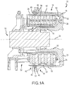
- Aircraft wheel braking assembly 10 such as may be found on an aircraft, in accordance with various embodiments is illustrated.
- Aircraft wheel braking assembly may, for example, comprise a bogie axle 12, a wheel 14 including a hub 16 and a wheel well 18, a web 20, a torque take-out assembly 22, one or more torque bars 24, a wheel rotational axis 26, a wheel well recess 28, an actuator 30, multiple brake rotors 32, multiple brake stators 34, a pressure plate 36, an end plate 38, a heat shield 40, multiple heat shield sections 42, multiple heat shield carriers 44, an air gap 46, multiple torque bar bolts 48, a torque bar pin 50, a wheel web hole 52, multiple heat shield fasteners 53, multiple rotor lugs 54, and multiple stator slots 56.
- FIG. 1B illustrates a portion of aircraft wheel braking assembly 10 as viewed into wheel well 18 and wheel well recess 28.
- the various components of aircraft wheel braking assembly 10 may be subjected to the application of compositions and methods for protecting the components from oxidation.
- Brake disks e.g., interleaved rotors 32 and stators 34
- Rotors 32 are secured to torque bars 24 for rotation with wheel 14, while stators 34 are engaged with torque take-out assembly 22.
- At least one actuator 30 is operable to compress interleaved rotors 32 and stators 34 for stopping the aircraft.
- actuator 30 is shown as a hydraulically actuated piston, but many types of actuators are suitable, such as an electromechanical actuator.
- Pressure plate 36 and end plate 38 are disposed at opposite ends of the interleaved rotors 32 and stators 34.
- Rotors 32 and stators 34 can comprise any material suitable for friction disks, including ceramics or carbon materials, such as a carbon/carbon composite.
- Torque take-out assembly 22 is secured to a stationary portion of the landing gear truck such as a bogie beam or other landing gear strut, such that torque take-out assembly 22 and stators 34 are prevented from rotating during braking of the aircraft.
- Carbon-carbon composites (also referred to herein as composite structures, composite substrates, and carbon-carbon composite structures, interchangeably) in the friction disks may operate as a heat sink to absorb large amounts of kinetic energy converted to heat during slowing of the aircraft.
- Heat shield 40 may reflect thermal energy away from wheel well 18 and back toward rotors 32 and stators 34.
- FIG. 1A a portion of wheel well 18 and torque bar 24 is removed to better illustrate heat shield 40 and heat shield segments 42.
- heat shield 40 is attached to wheel 14 and is concentric with wheel well 18. Individual heat shield sections 42 may be secured in place between wheel well 18 and rotors 32 by respective heat shield carriers 44 fixed to wheel well 18.
- Air gap 46 is defined annularly between heat shield segments 42 and wheel well 18.
- Torque bars 24 and heat shield carriers 44 can be secured to wheel 14 using bolts or other fasteners.
- Torque bar bolts 48 can extend through a hole formed in a flange or other mounting surface on wheel 14.
- Each torque bar 24 can optionally include at least one torque bar pin 50 at an end opposite torque bar bolts 48, such that torque bar pin 50 can be received through wheel web hole 52 in web 20.
- Heat shield sections 42 and respective heat shield carriers 44 can then be fastened to wheel well 18 by heat shield fasteners 53.
- carbon-carbon composites may be prone to material loss from oxidation of the carbon.
- various carbon-carbon composite components of aircraft wheel braking assembly 10 may experience both catalytic oxidation and inherent thermal oxidation caused by heating the composite during operation.
- composite rotors 32 and stators 34 may be heated to sufficiently high temperatures that may oxidize the carbon surfaces exposed to air. At elevated temperatures, infiltration of air and contaminants may cause internal oxidation and weakening, especially in and around brake rotor lugs 54 or stator slots 56 securing the friction disks to the respective torque bar 24 and torque take-out assembly 22.
- carbon-carbon composite components of aircraft wheel braking assembly 10 may retain heat for a substantial time period after slowing the aircraft, oxygen from the ambient atmosphere may react with the carbon matrix and/or carbon fibers to accelerate material loss. Further, damage to brake components may be caused by the oxidation enlargement of cracks around fibers or enlargement of cracks in a reaction-formed porous barrier coating (e.g., a silicon-based barrier coating) applied to the carbon-carbon composite.
- a reaction-formed porous barrier coating e.g., a silicon-based barrier coating
- Elements identified in severely oxidized regions of carbon-carbon composite brake components include potassium (K) and sodium (Na). These alkali contaminants may come into contact with aircraft brakes as part of cleaning or de-icing materials. Other sources include salt deposits left from seawater or sea spray. These and other contaminants (e.g. Ca, Fe, etc.) can penetrate and leave deposits in pores of carbon-carbon composite aircraft brakes, including the substrate and any reaction-formed porous barrier coating. When such contamination occurs, the rate of carbon loss by oxidation can be increased by one to two orders of magnitude.
- components of aircraft wheel braking assembly 10 may reach operating temperatures in the range from about 100° C up to about 900° C.
- oxidation protection compositions and methods of the present disclosure may be readily adapted to many parts in this and other braking assemblies, as well as to other carbon-carbon composite structures susceptible to oxidation losses from infiltration of atmospheric oxygen and/or catalytic contaminants.
- a method for limiting an oxidation reaction in a composite structure may comprise forming a slurry, which may be an oxidation protection composition, by combining a pre-slurry composition comprising a first phosphate glass composition in the form of a glass frit, powder, or other suitable pulverized form with a first carrier fluid (such as, for example, water), applying the slurry to a composite structure, and heating the composite structure to a temperature sufficient to dry the carrier fluid and form an oxidation protection composition or coating (or oxidation inhibiting composition) on the composite structure, which in various embodiments may be referred to as a base layer.
- a slurry which may be an oxidation protection composition
- the slurry which may be an oxidation protection composition, may comprise additives to increase temperature resistance, to change chemical reactivity, to improve hydrolytic stability, and/or to increase the composite structure's resistance to oxidation, thereby tending to reduce mass loss of composite structure.
- the pre-slurry composition of the slurry may comprise one or more additives to increase temperature resistance of the oxidation protection coating.
- the one or more additives may include carbide, nitride, boron nitride, silicon carbide, titanium carbide, boron carbide, silicon oxycarbide, molybdenum disulfide, tungsten disulfide and/or silicon nitride.
- an additive may include molybdenum disulfide (MoS 2 ), tungsten disulfide (WS 2 ), and/or boron nitride (BN).
- MoS 2 molybdenum disulfide
- WS 2 tungsten disulfide
- BN boron nitride
- the pre-slurry composition of the slurry may comprise a first additive, such as molybdenum disulfide, tungsten disulfide, and/or boron nitride.
- the pre-slurry composition of the slurry may further comprise a second additive, such as molybdenum disulfide, tungsten disulfide, and/or boron nitride.
- the pre-slurry composition of the slurry may further comprise additives, such as, for example, ammonium hydroxide, ammonium dihydrogen phosphate, nanoplatelets (such as graphene-based nanoplatelets), among others to improve hydrolytic stability and/or to increase the composite structure's resistance to oxidation.
- a slurry may comprise acid aluminum phosphates having an aluminum (Al) to phosphoric acid (H 3 PO 4 ) ratio of 1 to 5 or less by weight.
- a slurry comprising acid aluminum phosphates having an aluminum (Al) to phosphoric acid (H 3 PO 4 ) ratio of 1 to 3 or less by weight, such as an Al:H 3 PO 4 ratio of between 1 to 2 and 1 to 3 by weight, tends to provide increased hydrolytic stability without substantially increasing composite structure mass loss.
- a slurry comprising acid aluminum phosphates having an Al:H 3 PO 4 ratio between 1:2 to 1:3 produces an increase in hydrolytic protection and an unexpected reduction in composite structure mass loss.
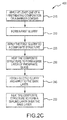
- Method 200 may, for example, comprise applying an oxidation inhibiting composition, or oxidation protection composition, to non-wearing surfaces of carbon-carbon composite brake components.
- method 200 may be used on the back face of pressure plate 36 and/or end plate 38, an inner diameter (ID) surface of stators 34 including slots 56, as well as outer diameter (OD) surfaces of rotors 32 including lugs 54.
- the oxidation protection composition or oxidation inhibiting composition of method 200 may be applied to preselected regions of a carbon-carbon composite structure that may be otherwise susceptible to oxidation.
- aircraft brake disks may have the oxidation inhibiting composition applied on or proximate stator slots 56 and/or rotor lugs 54.
- method 200 may comprise forming a first slurry 210, which may be an oxidation protection composition, by combining a first phosphate glass composition in the form of a glass frit, powder, or other suitable pulverized and/or ground form with a first carrier fluid (such as, for example, water).
- a first carrier fluid such as, for example, water
- the first phosphate glass composition may be combined with one or more additives to form a first pre-slurry composition.
- An additive may include carbide, nitride, boron nitride, silicon carbide, titanium carbide, boron carbide, silicon oxycarbide, molybdenum disulfide, tungsten disulfide and/or silicon nitride.
- the first pre-slurry composition may include a first additive, a second additive and/or a third additive.
- a first pre-slurry composition comprising a first additive may include molybdenum disulfide, tungsten disulfide or boron nitride.
- a first pre-slurry composition comprising a first additive and a second additive may include molybdenum disulfide and tungsten disulfide, molybdenum disulfide and boron nitride, or tungsten disulfide and boron nitride.
- a first pre-slurry composition comprising a first additive, a second additive and a third additive may include molybdenum disulfide, tungsten disulfide and boron nitride.
- the first phosphate glass composition of the first slurry is combined with a first additive, which includes a molybdenum disulfide (MoS 2 ) additive and/or a tungsten disulfide (WS 2 ) additive.
- a first additive which includes a molybdenum disulfide (MoS 2 ) additive and/or a tungsten disulfide (WS 2 ) additive.
- MoS 2 molybdenum disulfide
- WS 2 tungsten disulfide
- molybdenum disulfide such as hexagonal molybdenum disulfide (h-MoS 2 )
- h-MoS 2 hexagonal molybdenum disulfide
- the pre-slurry composition may comprise between about 4.0 and 9.0 percent molybdenum disulfide by mass, wherein the term "about” in this context only means +/- 1 percent by mass. Further, the pre-slurry composition may comprise between about 7.0 and 9.0 percent molybdenum disulfide by mass, wherein the term "about” in this context only means +/- 1 percent by mass. Molybdenum disulfide may be prepared for addition to the first phosphate glass composition by, for example, ultrasonically exfoliating molybdenum disulfide in dimethylformamide (DMF), a solution of DMF and water, or 2-propanol solution.
- DMF dimethylformamide
- the molybdenum disulfide additive may comprise a molybdenum disulfide that has been prepared for addition to the first phosphate glass composition by crushing or milling (e.g., ball milling) the molybdenum disulfide. The resulting molybdenum disulfide may be combined with the first phosphate glass composition glass frit to form the pre-slurry composition.
- the first additive of the pre-slurry composition may comprise a tungsten disulfide additive.
- tungsten disulfide may be added to the first phosphate glass composition to form a resulting pre-slurry composition comprising between about 0.1 and 9.0 percent tungsten disulfide by mass, wherein the term "about” in this context only means +/- 0.1 percent by mass.
- the pre-slurry composition may comprise between about 0.25 and 7.5 percent tungsten disulfide by mass, wherein the term "about” in this context only means +/- 0.25 percent by mass.
- the pre-slurry composition may comprise between about 4.0 and 9.0 percent tungsten disulfide by mass, wherein the term "about” in this context only means +/- 1 percent by mass.
- Tungsten disulfide may be prepared for addition to the first phosphate glass composition by, for example, ultrasonically exfoliating tungsten disulfide in DMF, a solution of DMF and water, or 2-propanol solution.
- the tungsten disulfide additive may comprise a tungsten disulfide that has been prepared for addition to the first phosphate glass composition by crushing or milling (e.g., ball milling) the tungsten disulfide. The resulting tungsten disulfide may be combined with the first phosphate glass composition glass frit to form the pre-slurry composition.
- the first phosphate glass composition of the first pre-slurry composition may further be combined with a second additive, which includes a boron nitride additive.
- a boron nitride such as hexagonal boron nitride
- the pre-slurry composition may comprise between about 0.25 and 7.5 percent boron nitride by mass, wherein the term "about” in this context only means +/- 0.25 percent by mass.
- the pre-slurry composition may comprise between about 0.25 and 4.5 percent boron nitride by mass, wherein the term “about” in this context only means +/- 0.25 percent by mass.
- the pre-slurry composition may comprise between about 10 weight percent and about 30 weight percent of boron nitride, wherein the term “about” in this context only means +/- 2 weight percent.
- the pre-slurry composition may comprise between about 15 weight percent and 25 weight percent of boron nitride, wherein the term "about” in this context only means +/- 2% weight percent.
- the pre-slurry composition may comprise between about 17 weight percent and 29 weight percent of boron nitride, wherein the term "about” in this context only means +/- 2 weight percent.
- Boron nitride may be prepared for addition to the first phosphate glass composition by, for example, ultrasonically exfoliating boron nitride in DMF, a solution of DMF and water, or 2-propanol solution.
- the boron nitride additive may comprise a boron nitride that has been prepared for addition to the first phosphate glass composition by crushing or milling (e.g., ball milling) the boron nitride. The resulting boronitride may be combined with the first phosphate glass composition glass frit to form the pre-slurry composition.
- the pre-slurry composition may comprise a first additive and a second additive.
- the first additive may include molybdenum disulfide and the second additive may include boron nitride.
- the first additive may include tungsten disulfide and the second additive may include boron nitride.
- the ratio of the first additive to the second additive, MoS 2 or WS 2 to BN, is 17:1.
- the pre-slurry composition may further comprise a third additive.
- the first additive may include molybdenum disulfide, the second additive may include boron nitride and the third additive may include tungsten disulfide.
- the first phosphate glass composition may comprise one or more alkali metal glass modifiers, one or more glass network modifiers and/or one or more additional glass formers.
- boron oxide or a precursor may optionally be combined with the P 2 O 5 mixture to form a borophosphate glass, which has improved self-healing properties at the operating temperatures typically seen in aircraft braking assemblies.
- the phosphate glass and/or borophosphate glass may be characterized by the absence of an oxide of silicon. Further, the ratio of P 2 O 5 to metal oxide in the fused glass may be in the range from about 0.25 to about 5 by weight.
- Potential alkali metal glass modifiers may be selected from oxides of lithium, sodium, potassium, rubidium, cesium, and mixtures thereof.
- the glass modifier may be an oxide of lithium, sodium, potassium, or mixtures thereof.
- These or other glass modifiers may function as fluxing agents.
- Additional glass formers can include oxides of boron, silicon, sulfur, germanium, arsenic, antimony, and mixtures thereof.
- Suitable glass network modifiers include oxides of vanadium, aluminum, tin, titanium, chromium, manganese, iron, cobalt, nickel, copper, mercury, zinc, lead, zirconium, lanthanum, cerium, praseodymium, neodymium, samarium, europium, gadolinium, terbium, dysprosium, holmium, erbium, thulium, ytterbium, actinium, thorium, uranium, yttrium, gallium, magnesium, calcium, strontium, barium, tin, bismuth, cadmium, and mixtures thereof.
- the first phosphate glass composition may be prepared by combining the above alkali metal glass modifiers, glass network modifiers, glass formers and/or P 2 O 5 and heating them to a fusion temperature.
- the fusion temperature may be in the range from about 700° C (1292° F) to about 1500° C (2732° F).
- the resultant melt may then be cooled and pulverized and/or ground to form a glass frit or powder.
- the first phosphate glass composition may be annealed to a rigid, friable state prior to being pulverized.
- the first phosphate glass composition comprises from about 20 mol % to about 80 mol % of P 2 O 5 . In various embodiments, the first phosphate glass composition comprises from about 30 mol % to about 70 mol % P 2 O 5 , or precursor thereof. In various embodiments, the first phosphate glass composition comprises from about 40 to about 60 mol % of P 2 O 5 .
- the first phosphate glass composition may comprise from about 5 mol % to about 50 mol % of the alkali metal oxide. In various embodiments, the first phosphate glass composition comprises from about 10 mol % to about 40 mol % of the alkali metal oxide. Further, the first phosphate glass composition comprises from about 15 to about 30 mol % of the alkali metal oxide or one or more precursors thereof. In various embodiments, the first phosphate glass composition may comprise from about 0.5 mol % to about 50 mol % of one or more of the above-indicated glass formers. The first phosphate glass composition may comprise about 5 to about 20 mol % by weight of one or more of the above-indicated glass formers. As used herein, mol % is defined as the number of moles of a constituent per the total moles of the solution.
- the first phosphate glass composition can comprise from about 0.5 mol % to about 40 mol % of one or more of the above-indicated glass network modifiers.
- the first phosphate glass composition may comprise from about 2.0 mol % to about 25 mol % of one or more of the above-indicated glass network modifiers.
- the first phosphate glass composition may represented by the formula: a(A' 2 O) x (P 2 O 5 ) y1 b(G f O) y2 c(A"O) z [1]
- A' is selected from: lithium, sodium, potassium, rubidium, cesium, and mixtures thereof;
- G f is selected from: boron, silicon, sulfur, germanium, arsenic, antimony, and mixtures thereof;
- the first phosphate glass composition in glass frit form may be combined with additional components to form the first pre-slurry composition.
- crushed first phosphate glass composition in glass frit form may be combined with ammonium hydroxide, ammonium dihydrogen phosphate, nanoplatelets (such as graphene-based nanoplatelets), among others.
- nanoplatelets such as graphene-based nanoplatelets
- graphene nanoplatelets could be added to the first phosphate glass composition in glass frit form.
- the additional components may be combined and preprocessed before combining them with first phosphate glass composition in glass frit form.
- suitable additional components include, for example, surfactants such as, for example, an ethoxylated low-foam wetting agent and flow modifiers, such as, for example, polyvinyl alcohol, polyacrylate, or similar polymers.
- other suitable additional components may include additives to enhance impact resistance and/or to toughen the oxidation protection coating, such as, for example, at least one of whiskers, nanofibers or nanotubes consisting of nitrides, carbides, carbon, graphite, quartz, silicates, aluminosilicates, phosphates, and the like.
- additives to increase temperature resistance, to change chemical reactivity, enhance impact resistance and/or to toughen the oxidation protection coating may include silicon carbide whiskers, carbon nanofibers, molybdenum disulfide nanoplatelets, tungsten disulfide, boron nitride nanotubes and similar materials.
- the first pre-slurry composition may be combined with a first carrier fluid to form the first slurry.
- the first carrier fluid of the first slurry may comprise an acid aluminum phosphate wherein the ratio of Al:H 3 PO 4 may be between 1:2 to 1:5, between 1:2 to 1:3, between 1:3 to 1:5, between 1:2.2 to 1:3, between 1:2.5 to 1:3, between 1:2.7 to 1:3 or between 1:29 to 1:3, as measured by weight.
- Method 200 further comprises applying the first slurry to a composite structure 220.
- Applying the first slurry may comprise, for example, spraying or brushing the first slurry of the first phosphate glass composition on to an outer surface of the composite structure. Any suitable manner of applying the base layer to the composite structure is within the scope of the present disclosure.
- the composite structure may refer to a carbon-carbon composite structure.
- Method 200 further comprises a step 230 of heating the composite structure to form a base layer of phosphate glass.
- the composite structure may be heated (e.g., dried or baked) at a temperature in the range from about 150° C (302° F) to about 1000° C (1832° F).
- the composite structure is heated to a temperature in a range from about 600° C (1112° F) to about 1000° C (1832° F), or between about 150° C (302° F) to about 900° C (1652° F), or further, between about 400° C (752° F) to about 850° C (1562° F).
- Step 230 may, for example, comprise heating the composite structure for a period between about 0.5 hour and about 8 hours, wherein the term "about” in this context only means +/- 0.25 hours.
- the base layer may also be referred to as a coating.
- the composite structure may be heated to a first, lower temperature (for example, about 30° C (86° F) to about 400° C (752° F)) to bake or dry the base layer at a controlled depth.
- a second, higher temperature for example, about 300° C (572° F) to about 1000° C (1832° F)
- the duration of each heating step can be determined as a fraction of the overall heating time and can range from about 10% to about 50%, wherein the term "about" in this context only means +/- 5%.
- the duration of the lower temperature heating step(s) can range from about 20% to about 40% of the overall heating time, wherein the term "about” in this context only means +/- 5%.
- the lower temperature step(s) may occupy a larger fraction of the overall heating time, for example, to provide relatively slow heating up to and through the first lower temperature.
- the exact heating profile will depend on a combination of the first temperature and desired depth of the drying portion.
- Step 230 may be performed in an inert environment, such as under a blanket of inert gas or less reactive gas (e.g., nitrogen, argon, other noble gases and the like).
- a composite structure may be pretreated or warmed prior to application of the base layer to aid in the penetration of the base layer.
- Step 230 may be for a period of about 2 hours at a temperature of about 600°C (1112° F) to about 800°C (1472° F), wherein the term "about” in this context only means +/- 10°C.
- the composite structure and base layer may then be dried or baked in a non-oxidizing, inert or less reactive atmosphere, e.g., noble gasses and/or nitrogen (N 2 ), to optimize the retention of the first pre-slurry composition of the base layer in the pores of the composite structure.
- This retention may, for example, be improved by heating the composite structure to about 200°C (392° F) and maintaining the temperature for about 1 hour before heating the carbon-carbon composite to a temperature in the range described above.
- the temperature rise may be controlled at a rate that removes water without boiling, and provides temperature uniformity throughout the composite structure.
- Method 300 may, for example, comprise applying an oxidation inhibiting composition or oxidation protection composition to non-wearing surfaces of carbon-carbon composite brake components.
- Method 300 which comprises steps also found in method 200, may further comprise a step 240, similar to step 210, of forming a second slurry by combining a second pre-slurry composition, which may comprise a second phosphate glass composition in glass frit or powder form with a second carrier fluid (such as, for example, water).
- a second pre-slurry composition which may comprise a second phosphate glass composition in glass frit or powder form with a second carrier fluid (such as, for example, water).
- the second slurry may comprise an acid aluminum phosphate wherein the ratio of aluminum (Al) to phosphoric acid (H 3 PO 4 ) may be between 1:2 to 1:5, between 1:2 to 1:3, between 1:3 to 1:5, between 1:2.2 to 1:3, between 1:2.5 to 1:3, between 1:2.7 to 1:3 or between 1:29 to 1:3.
- Step 240 further comprises, similar to step 220, applying the second slurry to the base layer.
- Step 240 may comprise spraying or brushing the second slurry of the second phosphate glass composition on to an outer surface of the base layer. Any suitable manner of applying the sealing layer to the base layer is within the scope of the present disclosure.
- the second slurry may be substantially free of molybdenum disulfide, tungsten disulfide and boron nitride.
- the second slurry may be substantially free of carbide, nitride, boron nitride, silicon carbide, titanium carbide, boron carbide, silicon oxycarbide, molybdenum disulfide, tungsten disulfide, and silicon nitride. In this case, "substantially free” means less than 0.01 percent by weight.
- the second pre-slurry composition may comprise any of the glass compositions described in connection with the first phosphate glass composition, without the addition of a molybdenum disulfide additive, without the addition of a tungsten disulfide additive and without the addition of a boron nitride additive.
- the second pre-slurry composition may comprise the same pre-slurry composition and/or phosphate glass composition used to prepare the first pre-slurry composition and/or first phosphate glass composition.
- the second pre-slurry composition may comprise a different pre-slurry composition and/or phosphate glass composition than the first pre-slurry composition and/or first phosphate glass composition.
- the first slurry and the second slurry may be formulated to balance the durability, temperature resistance, chemical resistance, impact resistance, and self-healing properties of the oxidation protection coating on the composite structure.
- the first pre-slurry composition or first slurry may comprise additives to increase temperature resistance
- the second pre-slurry composition or second slurry may be formulated to improve the impact resistance and self-healing properties of the oxidation protection coating.
- the oxidation protection coating comprising the first and second pre-slurry compositions or slurries may have both increased temperature resistance and self-healing properties, thereby increasing the oxidation protection capability of the coating and reducing mass loss of composite structures at higher temperatures.
- Method 300 comprises a step 250 of heating the composite structure to form a sealing layer of phosphate glass over the base layer. Similar to step 230, the composite structure may be heated at a temperature sufficient to adhere the sealing layer to the base layer by, for example, drying or baking the carbon-carbon composite structure at a temperature in the range from about 200° C (392° F) to about 1000° C (1832° F).
- the composite structure is heated to a temperature in a range from about 650° C (1202° F) to about 900° C (1652° F), or between about 200° C (392° F) to about 900° C (1652° F), or further, between about 400° C (752° F) to about 850° C (1562° F), wherein in this context only, the term “about” means +/- 10° C.
- step 250 may, for example, comprise heating the composite structure for a period between about 0.5 hour and about 8 hours, where the term "about” in this context only means +/-0.25 hours.
- step 250 may comprise heating the composite structure to a first, lower temperature (for example, about 30°C (86°F) to about 300°C (572°F)) followed by heating at a second, higher temperature (for example, about 300°C (572°F) to about 1000°C (1832°F)). Further, step 250 may be performed in an inert environment, such as under a blanket of inert or less reactive gas (e.g., nitrogen, argon, other noble gases, and the like).
- a blanket of inert or less reactive gas e.g., nitrogen, argon, other noble gases, and the like.
- method 400 comprises applying at least one of a pretreating composition or a barrier coating 215 prior to applying the first slurry.
- Pretreatment step 215 may, for example, comprise applying a first pretreating composition to an outer surface of a composite structure, such as a component of aircraft wheel braking assembly 10.
- the first pretreating composition comprises an aluminum oxide in water.
- the aluminum oxide may comprise an additive, such as a nanoparticle dispersion of aluminum oxide (for example, NanoBYK-3600®, sold by BYK Additives & Instruments).
- the first pretreating composition may further comprise a surfactant or a wetting agent.
- the composite structure may be porous, allowing the pretreating composition to penetrate at least a portion of the pores of the composite structure.
- the component after applying the first pretreating composition, is heated to remove water and fix the aluminum oxide in place.
- the component may be heated between about 100°C (212°F) and 200°C, and further, between 100°C (212°F) and 150 °C (392°F).
- Pretreatment step 215 may further comprise applying a second pretreating composition.
- the second pretreating composition comprises a phosphoric acid and an aluminum phosphate, aluminum hydroxide, or aluminum oxide.
- the second pretreating composition may further comprise, for example, a second metal salt such as a magnesium salt.
- the aluminum to phosphorus ratio of the aluminum phosphate is 1 to 5 or less by weight.
- the second pretreating composition may also comprise a surfactant or a wetting agent.
- the second pretreating composition is applied to the composite structure atop the first pretreating composition. The composite structure may then, for example, be heated.
- the composite structure may be heated between about 600 °C (1112 °F) and about 800 °C (1472 °F), and further, between about 650 °C (1202 °F) and 750 °C (1382 °F).
- Pretreatment step 215 may further comprise applying a barrier coating to an outer surface of a composite structure, such as a component of aircraft wheel braking assembly 10.
- the barrier coating composition may comprise carbides or nitrides, including at least one of a molybdenum disulfide, tungsten disulfide, boron nitride, silicon carbide, titanium carbide, boron carbide, silicon oxycarbide, and silicon nitride.
- the barrier coating may be formed by treating the composite structure with molten silicon. The molten silicon is reactive and may form a silicon carbide barrier on the composite structure.
- Step 215 may comprise, for example, application of the barrier coating by spraying, chemical vapor deposition (CVD), molten application, or brushing the barrier coating composition on to the outer surface of the carbon-carbon composite structure. Any suitable manner of applying the base layer to composite structure is within the scope of the present disclosure.
- TABLES 1 and 2 illustrates a variety of pre-slurry compositions, including phosphate glass compositions, in accordance with various embodiments.
- TABLE 1 Pre-slurry Composition A B C D E F Wt% Glass 75.01 75.01 76.71 69.74 80.20 73.22 Wt % Boron Nitride 0 0 21.07 28.09 17.53 24.54 Wt % o-AlPO4 0 2.27 0 0 0 0 TABLE 2
- Pre-slurry compositions A and B comprise phosphate glass compositions free of molybdenum disulfide, tungsten disulfide, and boron nitride.
- compositions A and B may be suitable sealing layers, such as the sealing layer applied in step 240 of methods 300 and 400.
- Pre-slurry compositions C, D, E, F, H, J, K, L, M, N, P and Q comprise phosphate glass and boron nitride and/or molybdenum disulfide additives.
- pre-slurry compositions H, J, K, L, M, N, P and Q may illustrate suitable base layers, such as base layers applied in step 220 of methods 200, 300, and 400.
- the boron nitride content of pre-slurry compositions C, D, E, and F varies between about 17.53 and 28.09 weight percent boron nitride. Molybdenum disulfide or tungsten disulfide may be substituted for boron nitride in pre-slurry compositions C, D, E, and F.
- the boron nitride content of pre-slurry compositions H, J, K, L, and N varies between about 0 and 7.17 percent boron nitride by mass.
- Pre-slurry composition Q represents a pre-slurry composition which may include one or more additives, such as of molybdenum disulfide, tungsten disulfide and/or boron nitride.
- a mass percent of additives in the first pre-slurry composition may represented by the formula: % Y MoS + % Z WS + % X BN
- a mass percent of molybdenum disulfide may range from 0 to 8.65.
- a mass percent of tungsten disulfide, shown by %Z WS , may range from 0 to 8.65.
- a mass percent of boron nitride, shown by %X BN may range from 0 to 8.65.
- the base layers and sealing layers shown in TABLE 3 are the same as shown in TABLE 1, with like labeling A, B, C, D, E and F.
- a base layer of formed of phosphate glass in compositions C, D, E, F, H, J, K, L, M, N, P and/or Q comprising molybdenum disulfide, tungsten disulfide and/or boron nitride are applied as slurry (i.e. a first slurry of a first phosphate glass composition) to a composite structure.
- Compositions A, B, C, D, E, F, H, J, K, L, M, N, P and/or Q may be oxidation protection compositions.
- a sealing layer formed of composition A and/or B is applied over the base layer (i.e. a second slurry of a second phosphate glass composition).
- a sealing layer formed of composition A is applied over a base layer of phosphate glass formed of compositions C, D, E and F.
- the composite structure having the base layer exhibited a lower weight loss to oxidation at temperatures at and above 675° C (1250° F) than composite structures having layer A by itself.
- FIG. 3 illustrates the data from TABLE 3, with percent weight loss on the y axis and exposure time in hours on the x axis. Examples of table 3 and figure 3 do not fall within the scope of the claims.
- FIG. 4 a number of combinations are illustrated, including various combinations of pre-treatment (such as, for example, as may be performed by pretreatment step 215), base layers, and sealing layers.
- the base layer and sealing layers are shown in FIG. 4 with the same labeling as shown in TABLE 1, A through F.
- FIG. 4 illustrates that the performance of a composition comprising a base layer of glass composition F and a sealing layer B provides improved oxidation protection over a pretreated composite structure having only sealing layer B.
- Other combinations include a base layer of glass composition F and a sealing layer A (without pre-treatment), a pretreatment with sealing layer A only, a base layer of F with a sealing layer of A (with pre-treatment).
- TABLES 4 and 5 illustrate a variety of slurries comprising pre-slurry compositions, including phosphate glass compositions, prepared in accordance with various embodiments. Examples A, Bl, B2, C, D, E, F and G from Table 4 do not fall within the scope of the first slurry of the claims.
- TABLE 6 illustrates a variety of aluminum phosphate solutions in accordance with various embodiments.
- Acid aluminum phosphate solutions AIPO 1:4 AlPO 1:3.5 AlPO 1:3 AIPO 1:2.5 AIPO 1:2 Component MW Amount (grams) H 2 O 18.01 60.10 60.65 61.42 62.50 64.08 H 3 PO 4 (85%) 98.00 100.00 100.00 100.00 100.00 Al(OH) 3 78.00 19.90 22.74 26.53 31.85 39.80 Al:P 0.250 0.286 0.333 0.400 0.500
- oxidation protection system slurries comprising a phosphate glass composition glass frit in a carrier fluid (i.e., water) and various additives including h -molybdenum disulfide, h -boron nitride, graphene nanoplatelets, a surfactant, a flow modifier such as, for example, polyvinyl alcohol, polyacrylate or similar polymer, ammonium dihydrogen phosphate, ammonium hydroxide, and acid aluminum phosphates with Al:H 3 PO 4 ratios of between 1 to 2 and 1 to 5 by weight were prepared.
- a carrier fluid i.e., water
- various additives including h -molybdenum disulfide, h -boron nitride, graphene nanoplatelets, a surfactant, a flow modifier such as, for example, polyvinyl alcohol, polyacrylate or similar polymer, ammonium dihydrogen phosphate, ammonium hydroxide, and acid aluminum phosphat
- slurry example G contained h -boron nitride, graphene nanoplatelets, and an acid aluminum phosphate solution with an aluminum to phosphorus ratio of 1:2.5 (see TABLE 4).
- slurry example H contained h-molybdenum disulfide, h -boron nitride, graphene nanoplatelets, and an acid aluminum phosphate solution with an aluminum to phosphorus ratio of 1:2.5.
- slurry example L contained h -molybdenum disulfide, graphene nanoplatelets, and an acid aluminum phosphate solution with an aluminum to phosphorus ratio of 1:2.5.
- slurry example Q represents a composition which may include one or more additives, such as of molybdenum disulfide, tungsten disulfide and/or boron nitride.
- a quantity or mass (in grams) of the one or more additives in the first pre-slurry composition may represented by the formula: Y MoS + Z WS + X BN
- a mass of molybdenum disulfide shown by Y MoS , may range from 0 to 8.75.
- a mass of tungsten disulfide, shown by Z WS may range from 0 to 8.75.
- a mass of boron nitride, shown by X BN may range from 0 to 8.75.
- Examples C, D, E, F, G, H, J, K, L, M, N, and P were applied to 50 gram carbon-carbon composite structure coupons and cured in inert atmosphere under heat at 899° C (1650° F). After cooling, glazes (examples A, B1 or B2) were applied atop the cured layer and the coupons were fired again in an inert atmosphere.
- a control coupon was pretreated with an alumina nanoparticle and given an acid aluminum phosphate base layer with a Al:H 3 PO 4 ratio of about 1 to 3.0, as described in various embodiments, and cured under an inert atmosphere.
- a control glaze was prepared as a slurry comprising a phosphate glass composition, water, ammonium dihydrogen phosphate, and aluminum orthophosphate.
- the control glaze (example B1) was applied atop the cured pretreated control and then fired again under an inert atmosphere forming, for example, a base layer. After cooling, the coupons were subjected to isothermal oxidation testing a 760°C (1400°F) over a period of 24 hours while monitoring mass loss.
- the composite structures formed from the slurries of C, D, E, F, and G do not fall within the scope of the claims.
- the control includes a pretreated composite structure having only base layer B. Percent weight loss is shown in the y axis and exposure time is shown in the x axis.
- an acid aluminum phosphate with ratio of Al:H 3 PO 4 of between 1:2 and 1:3 reduces mass losses due to oxidation by between two times to over ten times (i.e., an order of magnitude).
- the control After 24 hours at 760°C (1400°F) the control had lost 24.1% of its mass in comparison the best performing test sample which had lost only 0.7% of its mass.
- references to "one embodiment,” “an embodiment,” “an example embodiment,” etc. indicate that the embodiment described may include a particular feature, structure, or characteristic, but every embodiment may not necessarily include the particular feature, structure, or characteristic. Moreover, such phrases are not necessarily referring to the same embodiment. Further, when a particular feature, structure, or characteristic is described in connection with an embodiment, it is submitted that it is within the knowledge of one skilled in the art to affect such feature, structure, or characteristic in connection with other embodiments whether or not explicitly described. After reading the description, it will be apparent to one skilled in the relevant art(s) how to implement the disclosure in alternative embodiments.
- the terms "comprises,” “comprising,” or any other variation thereof, are intended to cover a non-exclusive inclusion, such that a process, method, article, or apparatus that comprises a list of elements does not include only those elements but may include other elements not expressly listed or inherent to such process, method, article, or apparatus.
Claims (10)
- Verfahren zum Beschichten einer Kohlenstoff-Kohlenstoff-Verbundwerkstoffstruktur, umfassend:Auftragen einer ersten Aufschlämmung einer ersten Phosphatglaszusammensetzung auf einer Außenfläche der Verbundwerkstoffstruktur, wobei die erste Aufschlämmung einen ersten Zusatzstoff, der zumindest eines von Molybdändisulfid oder Wolframdisulfid beinhaltet, und einen zweiten Zusatzstoff, der Bornitrid beinhaltet, umfasst; undErwärmen der Verbundwerkstoffstruktur auf eine Temperatur, die ausreichend ist, um eine Basisschicht zu bilden, die an der Verbundwerkstoffstruktur anhaftet,dadurch gekennzeichnet, dass das Verhältnis des ersten Zusatzstoffes zu dem zweiten Zusatzstoff 17:1 ist.
- Verfahren nach Anspruch 1, ferner umfassend das Bilden einer ersten Voraufschlämmungszusammensetzung durch Kombinieren des ersten Zusatzstoffes mit einer ersten Glasfritte, die die erste Phosphatglaszusammensetzung umfasst.
- Verfahren nach Anspruch 2, wobei das Verfahren ferner das Bilden der ersten Aufschlämmung durch Kombinieren der ersten Voraufschlämmungszusammensetzung mit einem ersten Trägerfluid umfasst, wobei das erste Trägerfluid ein saures Aluminiumphosphat umfasst.
- Verfahren nach einem vorhergehenden Anspruch, ferner umfassend:Auftragen einer zweiten Aufschlämmung einer zweiten Phosphatglaszusammensetzung auf die Basisschicht; undErwärmen der Verbundwerkstoffstruktur auf eine Temperatur, die ausreichend ist, um eine Dichtungsschicht zu bilden, die an der Basisschicht anhaftet.
- Verfahren nach Anspruch 4, wobei die zweite Aufschlämmung frei von Molybdändisulfid, Wolframdisulfid und Bornitrid ist.
- Verfahren nach einem vorhergehenden Anspruch, wobei die erste Phosphatglaszusammensetzung durch die Formel a(A'2O)x(P2O5)y1b(GfO)y2c(A"O)z dargestellt ist:wobei A' aus Folgendem ausgewählt ist: Lithium, Natrium, Kalium, Rubidium, Cäsium und Mischungen davon;Gf aus Folgendem ausgewählt ist: Bor, Silizium, Schwefel, Germanium, Arsen, Antimon und Mischungen davon;A" aus Folgendem ausgewählt ist: Vanadium, Aluminium, Zinn, Titan, Chrom, Mangan, Eisen, Kobalt, Nickel, Kupfer, Quecksilber, Zink, Blei, Zirkonium, Lanthan, Cerium, Praseodym, Neodym, Samarium, Europium, Gadolinium, Terbium, Dysprosium, Holmium, Erbium, Thulium, Ytterbium, Actinium, Thorium, Uran, Yttrium, Gallium, Magnesium, Calcium, Strontium, Barium, Zinn, Wismut, Cadmium und Mischungen davon;a eine Zahl im Bereich von 1 bis 5 ist;b eine Zahl im Bereich von 0 bis 10 ist;c eine Zahl im Bereich von 0 bis 30 ist;x eine Zahl im Bereich von 0,050 bis 0,500 ist;y1 eine Zahl im Bereich von 0,100 bis 0,950 ist;y2 eine Zahl im Bereich von 0 bis 0,20 ist; undz eine Zahl im Bereich von 0,01 bis 0,5 ist;


- Artikel, umfassend:eine Kohlenstoff-Kohlenstoff-Verbundwerkstoffstruktur; undeine Oxidationsschutzzusammensetzung, die eine Basisschicht beinhaltet, die an einer Außenfläche der Verbundwerkstoffstruktur angeordnet ist, wobei die Basisschicht eine erste Phosphatglaszusammensetzung umfasst, die einen ersten Zusatzstoff aufweist, der in der gesamten Basisschicht dispergiert ist, wobei der erste Zusatzstoff zumindest eines von Molybdändisulfid oder Wolframdisulfid beinhaltet, und wobei die Basisschicht ferner einen zweiten Zusatzstoff umfasst, der Bornitrid beinhaltet,dadurch gekennzeichnet, dass ein Verhältnis des ersten Zusatzstoffes zu dem zweiten Zusatzstoff 17:1 ist.
- Artikel nach Anspruch 7, ferner umfassend eine Dichtungsschicht, die an einer Außenfläche der Basisschicht angeordnet ist, wobei die Dichtungsschicht eine zweite Phosphatglaszusammensetzung umfasst und wobei die Dichtungsschicht frei von Bornitrid, Molybdändisulfid und Wolframdisulfid ist.
- Oxidationsschutzzusammensetzung, umfassend:eine erste Phosphatglaszusammensetzung, die einen ersten Zusatzstoff, der zumindest eines von Molybdändisulfid oder Wolframdisulfid beinhaltet, und einen zweiten Zusatzstoff, der Bornitrid beinhaltet, aufweist; undein erstes Trägerfluid,dadurch gekennzeichnet, dass das Verhältnis des ersten Zusatzstoffes zu dem zweiten Zusatzstoff 17:1 ist.
- Oxidationsschutzzusammensetzung nach Anspruch 9, wobei das erste Trägerfluid ein saures Aluminiumphosphat umfasst, und/oder wobei die erste Phosphatglaszusammensetzung durch die Formel a(A'2O)x(P2O5)y1b(GfO)y2c(A"O)z dargestellt ist:wobei A' aus Folgendem ausgewählt ist: Lithium, Natrium, Kalium, Rubidium, Cäsium und Mischungen davon;Gf aus Folgendem ausgewählt ist: Bor, Silizium, Schwefel, Germanium, Arsen, Antimon und Mischungen davon;A" aus Folgendem ausgewählt ist: Vanadium, Aluminium, Zinn, Titan, Chrom, Mangan, Eisen, Kobalt, Nickel, Kupfer, Quecksilber, Zink, Blei, Zirkonium, Lanthan, Cerium, Praseodym, Neodym, Samarium, Europium, Gadolinium, Terbium, Dysprosium, Holmium, Erbium, Thulium, Ytterbium, Actinium, Thorium, Uran, Yttrium, Gallium, Magnesium, Calcium, Strontium, Barium, Zinn, Wismut, Cadmium und Mischungen davon;a eine Zahl im Bereich von 1 bis 5 ist;b eine Zahl im Bereich von 0 bis 10 ist;c eine Zahl im Bereich von 0 bis 30 ist;x eine Zahl im Bereich von 0,050 bis 0,500 ist;y1 eine Zahl im Bereich von 0,100 bis 0,950 ist;y2 eine Zahl im Bereich von 0 bis 0,20 ist; undz eine Zahl im Bereich von 0,01 bis 0,5 ist;


Applications Claiming Priority (1)
| Application Number | Priority Date | Filing Date | Title |
|---|---|---|---|
| US15/174,537 US20170349825A1 (en) | 2016-06-06 | 2016-06-06 | Nanocomposite coatings for oxidation protection of composites |
Publications (2)
| Publication Number | Publication Date |
|---|---|
| EP3255027A1 EP3255027A1 (de) | 2017-12-13 |
| EP3255027B1 true EP3255027B1 (de) | 2019-12-18 |
Family
ID=59061843
Family Applications (1)
| Application Number | Title | Priority Date | Filing Date |
|---|---|---|---|
| EP17174481.6A Active EP3255027B1 (de) | 2016-06-06 | 2017-06-06 | Beschichtungen zum oxidationsschutz von verbundwerkstoffen |
Country Status (2)
| Country | Link |
|---|---|
| US (1) | US20170349825A1 (de) |
| EP (1) | EP3255027B1 (de) |
Families Citing this family (8)
| Publication number | Priority date | Publication date | Assignee | Title |
|---|---|---|---|---|
| US10087101B2 (en) | 2015-03-27 | 2018-10-02 | Goodrich Corporation | Formulations for oxidation protection of composite articles |
| US10465285B2 (en) | 2016-05-31 | 2019-11-05 | Goodrich Corporation | High temperature oxidation protection for composites |
| US10377675B2 (en) | 2016-05-31 | 2019-08-13 | Goodrich Corporation | High temperature oxidation protection for composites |
| US10508206B2 (en) | 2016-06-27 | 2019-12-17 | Goodrich Corporation | High temperature oxidation protection for composites |
| US10526253B2 (en) | 2016-12-15 | 2020-01-07 | Goodrich Corporation | High temperature oxidation protection for composites |
| GB2572764B (en) * | 2018-04-09 | 2023-06-07 | Applied Graphene Mat Uk Ltd | Corrosion protection for metallic substrates |
| US11046619B2 (en) | 2018-08-13 | 2021-06-29 | Goodrich Corporation | High temperature oxidation protection for composites |
| US11634213B2 (en) | 2018-11-14 | 2023-04-25 | Goodrich Corporation | High temperature oxidation protection for composites |
Family Cites Families (4)
| Publication number | Priority date | Publication date | Assignee | Title |
|---|---|---|---|---|
| US6913821B2 (en) * | 1999-03-04 | 2005-07-05 | Honeywell International Inc. | Fluidizing oxidation protection systems |
| US20140227511A1 (en) * | 2013-02-13 | 2014-08-14 | Goodrich Corporation | Formulations and methods for oxidation protection of composite articles |
| US10087101B2 (en) * | 2015-03-27 | 2018-10-02 | Goodrich Corporation | Formulations for oxidation protection of composite articles |
| US20170267595A1 (en) * | 2016-03-21 | 2017-09-21 | Goodrich Corporation | High temperature oxidation protection for composites |
-
2016
- 2016-06-06 US US15/174,537 patent/US20170349825A1/en not_active Abandoned
-
2017
- 2017-06-06 EP EP17174481.6A patent/EP3255027B1/de active Active
Non-Patent Citations (1)
| Title |
|---|
| None * |
Also Published As
| Publication number | Publication date |
|---|---|
| US20170349825A1 (en) | 2017-12-07 |
| EP3255027A1 (de) | 2017-12-13 |
Similar Documents
| Publication | Publication Date | Title |
|---|---|---|
| EP3222602B1 (de) | Hochtemperaturoxidationsschutz für verbundstoffe | |
| EP3255027B1 (de) | Beschichtungen zum oxidationsschutz von verbundwerkstoffen | |
| EP3252028B1 (de) | Hochtemperaturoxidationsschutz für verbundstoffe | |
| US10689290B2 (en) | Formulations for oxidation protection of composite articles | |
| EP2767529B1 (de) | Formulierungen und Verfahren zum Oxidationsschutz von Verbundgegenständen | |
| US11168222B2 (en) | High temperature oxidation protection for composites | |
| EP3072866B1 (de) | Mehrphasige zusammensetzungen zum oxidationsschutz von verbundgegenständen | |
| US11091402B2 (en) | High temperature oxidation protection for composites | |
| EP3521265B1 (de) | Hochtemperaturoxidationsschutz für verbundstoffe | |
| EP3842404A1 (de) | Hochtemperaturoxidationsschutz für verbundstoffe | |
| EP3590910A1 (de) | Hochtemperaturoxidationsschutz für verbundstoffe | |
| US11634213B2 (en) | High temperature oxidation protection for composites | |
| EP3611144A1 (de) | Hochtemperaturoxidationsschutz für verbundstoffe | |
| EP4086234A1 (de) | Hochtemperaturoxidationsschutz für kohlenstoff-kohlenstoff-verbundwerkstoffe | |
| EP4180408A1 (de) | Hochtemperaturoxidationsschutz für kohlenstoff-kohlenstoff-verbundstoffe |
Legal Events
| Date | Code | Title | Description |
|---|---|---|---|
| PUAI | Public reference made under article 153(3) epc to a published international application that has entered the european phase |
Free format text: ORIGINAL CODE: 0009012 |
|
| STAA | Information on the status of an ep patent application or granted ep patent |
Free format text: STATUS: THE APPLICATION HAS BEEN PUBLISHED |
|
| AK | Designated contracting states |
Kind code of ref document: A1 Designated state(s): AL AT BE BG CH CY CZ DE DK EE ES FI FR GB GR HR HU IE IS IT LI LT LU LV MC MK MT NL NO PL PT RO RS SE SI SK SM TR |
|
| AX | Request for extension of the european patent |
Extension state: BA ME |
|
| STAA | Information on the status of an ep patent application or granted ep patent |
Free format text: STATUS: REQUEST FOR EXAMINATION WAS MADE |
|
| STAA | Information on the status of an ep patent application or granted ep patent |
Free format text: STATUS: EXAMINATION IS IN PROGRESS |
|
| 17P | Request for examination filed |
Effective date: 20180613 |
|
| RBV | Designated contracting states (corrected) |
Designated state(s): AL AT BE BG CH CY CZ DE DK EE ES FI FR GB GR HR HU IE IS IT LI LT LU LV MC MK MT NL NO PL PT RO RS SE SI SK SM TR |
|
| 17Q | First examination report despatched |
Effective date: 20180716 |
|
| GRAP | Despatch of communication of intention to grant a patent |
Free format text: ORIGINAL CODE: EPIDOSNIGR1 |
|
| STAA | Information on the status of an ep patent application or granted ep patent |
Free format text: STATUS: GRANT OF PATENT IS INTENDED |
|
| INTG | Intention to grant announced |
Effective date: 20190703 |
|
| GRAS | Grant fee paid |
Free format text: ORIGINAL CODE: EPIDOSNIGR3 |
|
| GRAA | (expected) grant |
Free format text: ORIGINAL CODE: 0009210 |
|
| STAA | Information on the status of an ep patent application or granted ep patent |
Free format text: STATUS: THE PATENT HAS BEEN GRANTED |
|
| AK | Designated contracting states |
Kind code of ref document: B1 Designated state(s): AL AT BE BG CH CY CZ DE DK EE ES FI FR GB GR HR HU IE IS IT LI LT LU LV MC MK MT NL NO PL PT RO RS SE SI SK SM TR |
|
| REG | Reference to a national code |
Ref country code: CH Ref legal event code: EP |
|
| REG | Reference to a national code |
Ref country code: IE Ref legal event code: FG4D |
|
| REG | Reference to a national code |
Ref country code: DE Ref legal event code: R096 Ref document number: 602017009763 Country of ref document: DE |
|
| REG | Reference to a national code |
Ref country code: AT Ref legal event code: REF Ref document number: 1214442 Country of ref document: AT Kind code of ref document: T Effective date: 20200115 |
|
| REG | Reference to a national code |
Ref country code: NL Ref legal event code: MP Effective date: 20191218 |
|
| PG25 | Lapsed in a contracting state [announced via postgrant information from national office to epo] |
Ref country code: FI Free format text: LAPSE BECAUSE OF FAILURE TO SUBMIT A TRANSLATION OF THE DESCRIPTION OR TO PAY THE FEE WITHIN THE PRESCRIBED TIME-LIMIT Effective date: 20191218 Ref country code: NO Free format text: LAPSE BECAUSE OF FAILURE TO SUBMIT A TRANSLATION OF THE DESCRIPTION OR TO PAY THE FEE WITHIN THE PRESCRIBED TIME-LIMIT Effective date: 20200318 Ref country code: GR Free format text: LAPSE BECAUSE OF FAILURE TO SUBMIT A TRANSLATION OF THE DESCRIPTION OR TO PAY THE FEE WITHIN THE PRESCRIBED TIME-LIMIT Effective date: 20200319 Ref country code: SE Free format text: LAPSE BECAUSE OF FAILURE TO SUBMIT A TRANSLATION OF THE DESCRIPTION OR TO PAY THE FEE WITHIN THE PRESCRIBED TIME-LIMIT Effective date: 20191218 Ref country code: LV Free format text: LAPSE BECAUSE OF FAILURE TO SUBMIT A TRANSLATION OF THE DESCRIPTION OR TO PAY THE FEE WITHIN THE PRESCRIBED TIME-LIMIT Effective date: 20191218 Ref country code: LT Free format text: LAPSE BECAUSE OF FAILURE TO SUBMIT A TRANSLATION OF THE DESCRIPTION OR TO PAY THE FEE WITHIN THE PRESCRIBED TIME-LIMIT Effective date: 20191218 Ref country code: BG Free format text: LAPSE BECAUSE OF FAILURE TO SUBMIT A TRANSLATION OF THE DESCRIPTION OR TO PAY THE FEE WITHIN THE PRESCRIBED TIME-LIMIT Effective date: 20200318 |
|
| REG | Reference to a national code |
Ref country code: LT Ref legal event code: MG4D |
|
| PG25 | Lapsed in a contracting state [announced via postgrant information from national office to epo] |
Ref country code: HR Free format text: LAPSE BECAUSE OF FAILURE TO SUBMIT A TRANSLATION OF THE DESCRIPTION OR TO PAY THE FEE WITHIN THE PRESCRIBED TIME-LIMIT Effective date: 20191218 Ref country code: RS Free format text: LAPSE BECAUSE OF FAILURE TO SUBMIT A TRANSLATION OF THE DESCRIPTION OR TO PAY THE FEE WITHIN THE PRESCRIBED TIME-LIMIT Effective date: 20191218 |
|
| PG25 | Lapsed in a contracting state [announced via postgrant information from national office to epo] |
Ref country code: AL Free format text: LAPSE BECAUSE OF FAILURE TO SUBMIT A TRANSLATION OF THE DESCRIPTION OR TO PAY THE FEE WITHIN THE PRESCRIBED TIME-LIMIT Effective date: 20191218 |
|
| PG25 | Lapsed in a contracting state [announced via postgrant information from national office to epo] |
Ref country code: NL Free format text: LAPSE BECAUSE OF FAILURE TO SUBMIT A TRANSLATION OF THE DESCRIPTION OR TO PAY THE FEE WITHIN THE PRESCRIBED TIME-LIMIT Effective date: 20191218 Ref country code: EE Free format text: LAPSE BECAUSE OF FAILURE TO SUBMIT A TRANSLATION OF THE DESCRIPTION OR TO PAY THE FEE WITHIN THE PRESCRIBED TIME-LIMIT Effective date: 20191218 Ref country code: PT Free format text: LAPSE BECAUSE OF FAILURE TO SUBMIT A TRANSLATION OF THE DESCRIPTION OR TO PAY THE FEE WITHIN THE PRESCRIBED TIME-LIMIT Effective date: 20200513 Ref country code: CZ Free format text: LAPSE BECAUSE OF FAILURE TO SUBMIT A TRANSLATION OF THE DESCRIPTION OR TO PAY THE FEE WITHIN THE PRESCRIBED TIME-LIMIT Effective date: 20191218 Ref country code: RO Free format text: LAPSE BECAUSE OF FAILURE TO SUBMIT A TRANSLATION OF THE DESCRIPTION OR TO PAY THE FEE WITHIN THE PRESCRIBED TIME-LIMIT Effective date: 20191218 |
|
| PG25 | Lapsed in a contracting state [announced via postgrant information from national office to epo] |
Ref country code: SM Free format text: LAPSE BECAUSE OF FAILURE TO SUBMIT A TRANSLATION OF THE DESCRIPTION OR TO PAY THE FEE WITHIN THE PRESCRIBED TIME-LIMIT Effective date: 20191218 Ref country code: IS Free format text: LAPSE BECAUSE OF FAILURE TO SUBMIT A TRANSLATION OF THE DESCRIPTION OR TO PAY THE FEE WITHIN THE PRESCRIBED TIME-LIMIT Effective date: 20200418 Ref country code: SK Free format text: LAPSE BECAUSE OF FAILURE TO SUBMIT A TRANSLATION OF THE DESCRIPTION OR TO PAY THE FEE WITHIN THE PRESCRIBED TIME-LIMIT Effective date: 20191218 |
|
| REG | Reference to a national code |
Ref country code: DE Ref legal event code: R097 Ref document number: 602017009763 Country of ref document: DE |
|
| REG | Reference to a national code |
Ref country code: AT Ref legal event code: MK05 Ref document number: 1214442 Country of ref document: AT Kind code of ref document: T Effective date: 20191218 |
|
| PLBE | No opposition filed within time limit |
Free format text: ORIGINAL CODE: 0009261 |
|
| STAA | Information on the status of an ep patent application or granted ep patent |
Free format text: STATUS: NO OPPOSITION FILED WITHIN TIME LIMIT |
|
| PG25 | Lapsed in a contracting state [announced via postgrant information from national office to epo] |
Ref country code: ES Free format text: LAPSE BECAUSE OF FAILURE TO SUBMIT A TRANSLATION OF THE DESCRIPTION OR TO PAY THE FEE WITHIN THE PRESCRIBED TIME-LIMIT Effective date: 20191218 Ref country code: DK Free format text: LAPSE BECAUSE OF FAILURE TO SUBMIT A TRANSLATION OF THE DESCRIPTION OR TO PAY THE FEE WITHIN THE PRESCRIBED TIME-LIMIT Effective date: 20191218 |
|
| 26N | No opposition filed |
Effective date: 20200921 |
|
| PG25 | Lapsed in a contracting state [announced via postgrant information from national office to epo] |
Ref country code: AT Free format text: LAPSE BECAUSE OF FAILURE TO SUBMIT A TRANSLATION OF THE DESCRIPTION OR TO PAY THE FEE WITHIN THE PRESCRIBED TIME-LIMIT Effective date: 20191218 Ref country code: SI Free format text: LAPSE BECAUSE OF FAILURE TO SUBMIT A TRANSLATION OF THE DESCRIPTION OR TO PAY THE FEE WITHIN THE PRESCRIBED TIME-LIMIT Effective date: 20191218 |
|
| REG | Reference to a national code |
Ref country code: DE Ref legal event code: R119 Ref document number: 602017009763 Country of ref document: DE |
|
| PG25 | Lapsed in a contracting state [announced via postgrant information from national office to epo] |
Ref country code: MC Free format text: LAPSE BECAUSE OF FAILURE TO SUBMIT A TRANSLATION OF THE DESCRIPTION OR TO PAY THE FEE WITHIN THE PRESCRIBED TIME-LIMIT Effective date: 20191218 Ref country code: IT Free format text: LAPSE BECAUSE OF FAILURE TO SUBMIT A TRANSLATION OF THE DESCRIPTION OR TO PAY THE FEE WITHIN THE PRESCRIBED TIME-LIMIT Effective date: 20191218 |
|
| REG | Reference to a national code |
Ref country code: CH Ref legal event code: PL |
|
| PG25 | Lapsed in a contracting state [announced via postgrant information from national office to epo] |
Ref country code: PL Free format text: LAPSE BECAUSE OF FAILURE TO SUBMIT A TRANSLATION OF THE DESCRIPTION OR TO PAY THE FEE WITHIN THE PRESCRIBED TIME-LIMIT Effective date: 20191218 |
|
| PG25 | Lapsed in a contracting state [announced via postgrant information from national office to epo] |
Ref country code: LU Free format text: LAPSE BECAUSE OF NON-PAYMENT OF DUE FEES Effective date: 20200606 |
|
| REG | Reference to a national code |
Ref country code: BE Ref legal event code: MM Effective date: 20200630 |
|
| PG25 | Lapsed in a contracting state [announced via postgrant information from national office to epo] |
Ref country code: IE Free format text: LAPSE BECAUSE OF NON-PAYMENT OF DUE FEES Effective date: 20200606 Ref country code: LI Free format text: LAPSE BECAUSE OF NON-PAYMENT OF DUE FEES Effective date: 20200630 Ref country code: CH Free format text: LAPSE BECAUSE OF NON-PAYMENT OF DUE FEES Effective date: 20200630 |
|
| PG25 | Lapsed in a contracting state [announced via postgrant information from national office to epo] |
Ref country code: BE Free format text: LAPSE BECAUSE OF NON-PAYMENT OF DUE FEES Effective date: 20200630 Ref country code: DE Free format text: LAPSE BECAUSE OF NON-PAYMENT OF DUE FEES Effective date: 20210101 |
|
| PG25 | Lapsed in a contracting state [announced via postgrant information from national office to epo] |
Ref country code: TR Free format text: LAPSE BECAUSE OF FAILURE TO SUBMIT A TRANSLATION OF THE DESCRIPTION OR TO PAY THE FEE WITHIN THE PRESCRIBED TIME-LIMIT Effective date: 20191218 Ref country code: MT Free format text: LAPSE BECAUSE OF FAILURE TO SUBMIT A TRANSLATION OF THE DESCRIPTION OR TO PAY THE FEE WITHIN THE PRESCRIBED TIME-LIMIT Effective date: 20191218 Ref country code: CY Free format text: LAPSE BECAUSE OF FAILURE TO SUBMIT A TRANSLATION OF THE DESCRIPTION OR TO PAY THE FEE WITHIN THE PRESCRIBED TIME-LIMIT Effective date: 20191218 |
|
| PG25 | Lapsed in a contracting state [announced via postgrant information from national office to epo] |
Ref country code: MK Free format text: LAPSE BECAUSE OF FAILURE TO SUBMIT A TRANSLATION OF THE DESCRIPTION OR TO PAY THE FEE WITHIN THE PRESCRIBED TIME-LIMIT Effective date: 20191218 |
|
| P01 | Opt-out of the competence of the unified patent court (upc) registered |
Effective date: 20230522 |
|
| PGFP | Annual fee paid to national office [announced via postgrant information from national office to epo] |
Ref country code: FR Payment date: 20230523 Year of fee payment: 7 |
|
| PGFP | Annual fee paid to national office [announced via postgrant information from national office to epo] |
Ref country code: GB Payment date: 20230523 Year of fee payment: 7 |