EP3254896B1 - Restraint track - Google Patents
Restraint track Download PDFInfo
- Publication number
- EP3254896B1 EP3254896B1 EP17172394.3A EP17172394A EP3254896B1 EP 3254896 B1 EP3254896 B1 EP 3254896B1 EP 17172394 A EP17172394 A EP 17172394A EP 3254896 B1 EP3254896 B1 EP 3254896B1
- Authority
- EP
- European Patent Office
- Prior art keywords
- restraint
- track
- lip
- cargo
- distal end
- Prior art date
- Legal status (The legal status is an assumption and is not a legal conclusion. Google has not performed a legal analysis and makes no representation as to the accuracy of the status listed.)
- Not-in-force
Links
Images


Classifications
-
- B—PERFORMING OPERATIONS; TRANSPORTING
- B60—VEHICLES IN GENERAL
- B60P—VEHICLES ADAPTED FOR LOAD TRANSPORTATION OR TO TRANSPORT, TO CARRY, OR TO COMPRISE SPECIAL LOADS OR OBJECTS
- B60P7/00—Securing or covering of load on vehicles
- B60P7/06—Securing of load
- B60P7/08—Securing to the vehicle floor or sides
- B60P7/0807—Attachment points
- B60P7/0815—Attachment rails or trellis
-
- B—PERFORMING OPERATIONS; TRANSPORTING
- B65—CONVEYING; PACKING; STORING; HANDLING THIN OR FILAMENTARY MATERIAL
- B65D—CONTAINERS FOR STORAGE OR TRANSPORT OF ARTICLES OR MATERIALS, e.g. BAGS, BARRELS, BOTTLES, BOXES, CANS, CARTONS, CRATES, DRUMS, JARS, TANKS, HOPPERS, FORWARDING CONTAINERS; ACCESSORIES, CLOSURES, OR FITTINGS THEREFOR; PACKAGING ELEMENTS; PACKAGES
- B65D90/00—Component parts, details or accessories for large containers
- B65D90/004—Contents retaining means
Definitions
- the present invention concerns a cargo restraint track. More particularly, but not exclusively, this invention concerns a universal cargo restraint track.
- cargo restraint tracks and fittings are commercially available to make efficient use of cargo spaces located within cargo carrying vehicles such as lorries, ships, and aircraft.
- cargo restraint tracks are known e.g. from EP 0 512 791 A1 , US 3 241 500 A , US 2015/110568 A1 and DE 43 41 230 C2 .
- the present invention seeks to mitigate the above-mentioned problems.
- the present invention provides, according to a first aspect, a cargo restraint track according to claim 1.
- the restraint track may comprise a length, a width, and a height.
- the restraint track may be longer than it is wide.
- the restraint track may be substantially longer than it is wide.
- the present invention may be used as a universal cargo restraint track which advantageously is arranged to engage with a variety of restraint devices.
- the cargo restraint track therefore reduces the number of different types of track which must be used in order to utilise a variety of different restraint devices.
- the apertures are configured to receive a distal end of the first restraint device, the distal end having an approximately circular cross-section.
- the apertures are configured to receive a distal end of the second restraint device, the distal end having an approximately rectangular cross-section and the first lip and second lip are each arranged to abut corresponding restraint flanges which project from the distal end of the second restraint device.
- One restraint flange may be moveable (under bias) to allow engagement and disengagement with the track.
- the first lip and second lip may define a receiving portion for receiving the third restraint device, such that the third restraint device may move along the length of the track but is restrained in other directions.
- Each aperture may be arranged to receive and engage with a trigger which forms part of the third restraint device.
- Each aperture is arranged to be engageable with each of the first, second, and third restraint devices.
- Each aperture may be arranged to be engageable with only one of the first, second, and third restraint devices at a time.
- Each aperture may be substantially identical in shape.
- Each aperture has a substantially circular cross-section, a first notch which extends in a radial direction out of the circumference of the circular cross-section towards the first lip, and a second notch which extends in a radial direction out of the circumference of the circular cross-section towards the second lip.
- the first notch may extend in a direction defining a notch axis.
- the notch axis may be perpendicular to the length of the track.
- the second notch may extend in a direction parallel with the notch axis.
- the second notch may extend along the notch axis.
- the first and second notches may be co-axial and extend in substantially opposite directions.
- the diameter of the substantially circular cross-section may be greater than 20 mm.
- the diameter of the substantially circular cross-section may be less than 30 mm.
- the diameter of the substantially circular cross-section may be less than 24 mm.
- the diameter of the circular cross-section may be approximately equal to 24 mm.
- the cargo restraint track may comprise a restraint surface with a length and the plurality of apertures may run along the length of the restraint surface.
- the restraint surface may be positioned between the first and second lips.
- a first arm may project from a first edge of the restraint surface and a second arm may project from a second, opposite, edge of the restraint surface, the restraint surface and first and second arms thereby forming a U-shaped section.
- the restraint track may comprise a height.
- the first and second arms may project along the height direction.
- the restraint surface may be spaced apart from the first and second lips.
- the restraint surface and first and second lips may be joined to a back plate.
- the restraint surface and first and second lips may be spaced apart from the back plate.
- the restraint surface, first and second lips, and back plate may all be substantially parallel to one another.
- the first notch of each aperture may pass through the first arm of the U-shaped section.
- the first arm of the U-shaped section may partially form each aperture.
- the second notch of each aperture may pass through the second arm of the U-shaped section.
- the second arm of the U-shaped section may partially form each aperture.
- the restraint track may comprise a back plate in a plane substantially parallel with, but spaced apart from, both of the first and second lips; the back plate arranged such that the cargo restraint track may be mounted to an external surface via the back plate.
- the back plate may connect the restraint surface with one of the first and second lips. There may be two back plates.
- the external surface is a surface that does not form part of the restraint track.
- the external surface may, for example, be located in the cargo hold of a vehicle such as a lorry, ship, or aircraft.
- a back plate may be arranged such that the restraint track can be mounted to the external surface using an adhesive.
- the back plate may comprise apertures arranged such that the restraint track can be mounted to the external surface using fasteners such as rivets or bolts.
- the first lip may comprise a first plurality of notches which run along an edge of the first lip
- the second lip may comprise a second plurality of notches which run along an edge of the second lip, the notches being arranged such that a fastening tool is able to be be passed through the notches in order to access the back plate.
- the end of a rivet gun may be passed through the notch in order to rivet the back plate to a securing surface, for example the wall of a container.
- Each of the notches may be semi-circular in shape.
- the notches may have a diameter.
- the diameter of each of the first plurality of notches may be coincident with an edge of the first lip.
- the diameter of each of the second plurality of notches may be coincident with an edge of the second lip.
- the cargo restraint track may comprise a symmetry line along the length of the cargo restraint track wherein at least one of the apertures, lips, and back plate are mirrored either side of the symmetry line.
- Each aperture may have a centre defined as the point at the centre of the circular cross-section.
- the symmetry line may be coincident with the centre of each of the apertures.
- the cargo restraint track is configured to engage with
- the restraint track may be formed from a single piece of material. Making the restraint track from a single piece of material may improve the strength and/or durability of the restraint track, and/or make the restraint track less expensive to manufacture.
- the material may be rolled steel.
- the material may be mild steel.
- the restraint track may be zinc plated after the restraint track has been formed from the single piece of material.
- the material may be galvanised steel.
- the material may be stainless steel.
- the restraint track may be cold rolled from steel coil.
- a container comprising a restraint track according to claim 1, wherein the cargo restraint track is mounted upon an internal surface of the container.
- a method of mounting a first restraint device upon a cargo restraint track comprising a distal end, the distal end comprising an approximately circular cross-section, wherein the method includes the step of inserting the distal end of the restraint device into an aperture located on the cargo restraint track.
- a method of mounting a second restraint device upon a cargo restraint track comprising a distal end, the distal end comprising an approximately rectangular cross-section with two restraint flanges projecting out of the distal end, wherein the method includes the steps of inserting the distal end of the second restraint device into an aperture located on the restraint track such that one of the restraint flanges engages with the first lip of the restraint track, and the other of the restraint flanges engages with the second lip of the cargo restraint track.
- a method of mounting a third restraint device upon a cargo restraint track comprising the steps of inserting the third restraint device into the receiving portion, moving the third restraint device along the length of the restraint track, and inserting the trigger into an aperture of the cargo restraint track.
- a method of creating a second deck within a cargo container comprising the steps of providing a first and second cargo restraint track according to the invention, the cargo restraint tracks being mounted upon opposite sides of the cargo container, providing a plurality of first restraint devices, each first restraint device comprising a first distal end and a second distal end, the distal ends comprising an approximately circular cross-section, wherein the method includes the steps of inserting the first distal end of each first restraint device into an aperture located on the first cargo restraint track, and inserting the second distal end of each first restraint device into an aperture located on the second cargo restraint track, wherein the plurality of first restraint devices form a second deck.
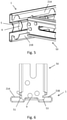
- a cargo restraint track 1 according to an embodiment of the invention is shown in Figure 1 .
- the cargo restraint track 1, which is formed by cold rolling steel coil, has a length and a width and is substantially longer than it is wide.
- the cargo restraint track 1 comprises a restraint surface 5 which runs along the length of the cargo restraint track 1 and a centre-line 3 which runs along the centre of the restraint surface 5, parallel to the length direction.
- the restraint surface 5 is arranged such that various load restraint fixings may be inserted into and through the front side of the restraint surface 5.
- a first arm 7A projects from a first edge of the restraint surface 5 and a second arm 7B projects from a second edge of the restraint surface 5, the first edge and second edge being located on opposite sides across the width of the restraint surface 5.
- the restraint surface 5, first arm 7A, and second arm 7B thereby form the three sides of a U-shaped channel.
- a multiplicity of receiving apertures 9 are formed in the restraint surface 5 and spaced along the centre-line 3 of the cargo restraint track 1.
- Each receiving aperture 9 consists of a circular hole 11 with a diameter of approximately 24 mm, the centre of the hole 11 being coincident with the centre-line 3 of the cargo restraint track 1.
- a first notch 13A extends radially out of the circumference of the circular hole 11 along a notch axis in a first direction and a second notch 13B extends radially out of the circumference of the circular hole 11 along the notch axis in a second, opposite, direction, the notch axis being perpendicular to the centre-line 3 and passing through the centre of the circular hole 11.
- Each receiving aperture 9 is thereby symmetrical about the centre-line 3 of the cargo restraint track 1.
- the notch extends through the walls of the U-shaped channel thereby forming a slot 15 which bridges the circular hole 11.
- a first back plate 17A projects from the distal end of the first arm 7A in a plane parallel with the restraint surface 5, away from the U-shaped section.
- the first back plate 17A is arranged with mounting holes 19 such that the cargo restraint track 1 may be mounted upon a surface which, for example, may be in the cargo hold of a lorry, ship, or aircraft, or a cargo transportation container, such as a freight container.
- the cargo restraint track 1 projects upwardly and then folds back on itself to form a first lip 21A which projects back towards the restraint surface 5, the first lip 21A being parallel to and spaced apart from the first back plate 17A.
- the first lip 21A is arranged such that various fittings may abut the first lip 21A.
- a first plurality of semi-circular notches 23A is formed along the free-edge of the first lip 21A, the free edge being the edge which is closest to the restraint surface 5, the semi-circular notches 23A being formed such that the diameter of each semi-circular notch 23A is parallel and coincident with the free-edge of the first lip 21A.
- the semi-circular notches are arranged such that a fastening tool such as, for example, a rivet gun may be passed through the notches in the first lip 21A in order to access the mounting holes 19 located in the first back plate 17A.
- the cargo restraint track 1 is symmetrical about its centre-line 3 such that the first arm 7A, first back plate 17A, and first abutting surface 21A are positioned on a first side of the cargo restraint track 1 and the second arm 7B, a second back plate 17B, and a second lip 21B is located on the second side of the cargo restraint track 1.
- a second plurality of semi-circular notches 23B is formed in the second lip 21B, the second plurality of semi-circular notches 23B being symmetrical to the first plurality of semi-circular notches 23A.
- the cargo restraint track 1 according to the presently described embodiment of the invention is thus arranged to receive various standard-sized cargo restraint fittings, as will now be described with reference to Figures 2 to 8 .
- Figure 2 shows a shoring pole 30 with standard 24 mm end-plug mounted within circular hole 11 of a receiving aperture 9.
- the cargo restraint track 1 therefore performs the function of a standard restraint track arranged for mounting of 24 mm end plugs.
- FIG 3 and Figure 4 show a captive head fitting 40 mounted within the cargo restraint track 1.
- the captive head fitting 40 slides into the profile of the cargo restraint track 1 from an open end.
- the first and second lips 21 of the cargo restraint track 1 abut corresponding surfaces 43 located on either side of the captive head fitting 40, as can be seen from the cross-sectional view shown in Figure 4 .
- the cargo restraint track 1 therefore holds the head fitting 40 captive, allowing movement only along the centre-line 3.
- the head has a spring loaded trigger 41 that locks into the circular hole 11 of a receiving aperture 9. The head can be repositioned along the centre-line 3 of the cargo restraint track 1 by lifting the trigger 41 and moving the head fitting 40 to the desired position.
- Figure 5 and Figure 6 show a standard slotted locking head beam fitting 50 mounted upon the cargo restraint track 1.
- the beam fitting 50 plugs directly into the slot 15 formed in a receiving aperture 9.
- the flange 53 projecting from the distal end of the head beam fitting 50 abuts the underside of one of the first and second lips 21 and the beam fitting 50 is locked into position by the spring loaded trigger 51 which abuts the other of first and second lips 21.
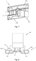
- FIG 7 and Figure 8 show a standard slotted locking head webbing sling fitting 60 mounted upon the cargo restraint track 1.
- the webbing sling fitting 60 plugs directly into the slot 15 formed in a receiving aperture 9.
- the flanges 63 projecting from each side of the webbing sling fitting 60 abut the undersides of the lips 21 of the cargo restraint track 1.
- the webbing sling fitting 60 is locked into position by the spring loaded trigger 61 which abuts one of the lips 21 of the cargo restraint track 1.
Landscapes
- Engineering & Computer Science (AREA)
- Mechanical Engineering (AREA)
- Transportation (AREA)
- Connection Of Plates (AREA)
Description
- The present invention concerns a cargo restraint track. More particularly, but not exclusively, this invention concerns a universal cargo restraint track.
- It is well known that cargo restraint tracks and fittings are commercially available to make efficient use of cargo spaces located within cargo carrying vehicles such as lorries, ships, and aircraft. Examples of such cargo restraint tracks are known e.g. from
EP 0 512 791 A1 ,US 3 241 500 A ,US 2015/110568 A1 andDE 43 41 230 C2 . - Through the use of various tracks and fittings it is possible, for example, to partition a cargo hold into multiple floors through the use of second deck beams. Another example would be fittings and corresponding track used to provide garment rails for convenient transport of garments. Various straps and cargo restraint mechanisms may also be used in cargo carrying containers.
- One problem associated with the use of such tracks and fittings is cross-compatibility: certain fittings require the use of certain tracks. Thus it may not be possible to switch between the use of different fittings (for example, second decking and garment rails) without either having multiple types of track installed within a cargo bay (which may lead to inefficient use of space and an increase in cost) or without having to refit the cargo bay between jobs (which may lead to inefficient use of time).
- The present invention seeks to mitigate the above-mentioned problems.
- The present invention provides, according to a first aspect, a cargo restraint track according to
claim 1. - The restraint track may comprise a length, a width, and a height. The restraint track may be longer than it is wide. The restraint track may be substantially longer than it is wide.
- The present invention may be used as a universal cargo restraint track which advantageously is arranged to engage with a variety of restraint devices. The cargo restraint track therefore reduces the number of different types of track which must be used in order to utilise a variety of different restraint devices.
- The apertures are configured to receive a distal end of the first restraint device, the distal end having an approximately circular cross-section. The apertures are configured to receive a distal end of the second restraint device, the distal end having an approximately rectangular cross-section and the first lip and second lip are each arranged to abut corresponding restraint flanges which project from the distal end of the second restraint device.
- One restraint flange may be moveable (under bias) to allow engagement and disengagement with the track. The first lip and second lip may define a receiving portion for receiving the third restraint device, such that the third restraint device may move along the length of the track but is restrained in other directions.
- Each aperture may be arranged to receive and engage with a trigger which forms part of the third restraint device.
- Each aperture is arranged to be engageable with each of the first, second, and third restraint devices.
- Each aperture may be arranged to be engageable with only one of the first, second, and third restraint devices at a time.
- Each aperture may be substantially identical in shape.
- Each aperture has a substantially circular cross-section, a first notch which extends in a radial direction out of the circumference of the circular cross-section towards the first lip, and a second notch which extends in a radial direction out of the circumference of the circular cross-section towards the second lip. The first notch may extend in a direction defining a notch axis. The notch axis may be perpendicular to the length of the track. The second notch may extend in a direction parallel with the notch axis. The second notch may extend along the notch axis. The first and second notches may be co-axial and extend in substantially opposite directions.
- The diameter of the substantially circular cross-section may be greater than 20 mm. The diameter of the substantially circular cross-section may be less than 30 mm. The diameter of the substantially circular cross-section may be less than 24 mm. The diameter of the circular cross-section may be approximately equal to 24 mm.
- The cargo restraint track may comprise a restraint surface with a length and the plurality of apertures may run along the length of the restraint surface. The restraint surface may be positioned between the first and second lips. A first arm may project from a first edge of the restraint surface and a second arm may project from a second, opposite, edge of the restraint surface, the restraint surface and first and second arms thereby forming a U-shaped section. The restraint track may comprise a height. The first and second arms may project along the height direction. The restraint surface may be spaced apart from the first and second lips. The restraint surface and first and second lips may be joined to a back plate. The restraint surface and first and second lips may be spaced apart from the back plate. The restraint surface, first and second lips, and back plate may all be substantially parallel to one another.
- The first notch of each aperture may pass through the first arm of the U-shaped section. The first arm of the U-shaped section may partially form each aperture. The second notch of each aperture may pass through the second arm of the U-shaped section. The second arm of the U-shaped section may partially form each aperture.
- The restraint track may comprise a back plate in a plane substantially parallel with, but spaced apart from, both of the first and second lips; the back plate arranged such that the cargo restraint track may be mounted to an external surface via the back plate.
- The back plate may connect the restraint surface with one of the first and second lips. There may be two back plates.
- It will be understood that the external surface is a surface that does not form part of the restraint track. The external surface may, for example, be located in the cargo hold of a vehicle such as a lorry, ship, or aircraft. A back plate may be arranged such that the restraint track can be mounted to the external surface using an adhesive. The back plate may comprise apertures arranged such that the restraint track can be mounted to the external surface using fasteners such as rivets or bolts.
- The first lip may comprise a first plurality of notches which run along an edge of the first lip, and the second lip may comprise a second plurality of notches which run along an edge of the second lip, the notches being arranged such that a fastening tool is able to be be passed through the notches in order to access the back plate. For example, the end of a rivet gun may be passed through the notch in order to rivet the back plate to a securing surface, for example the wall of a container. Each of the notches may be semi-circular in shape. The notches may have a diameter. The diameter of each of the first plurality of notches may be coincident with an edge of the first lip. The diameter of each of the second plurality of notches may be coincident with an edge of the second lip.
- The cargo restraint track may comprise a symmetry line along the length of the cargo restraint track wherein at least one of the apertures, lips, and back plate are mirrored either side of the symmetry line. Each aperture may have a centre defined as the point at the centre of the circular cross-section. The symmetry line may be coincident with the centre of each of the apertures.
- According to the invention the cargo restraint track is configured to engage with
- a first, approximately cylindrical, restraint device,
- a second, beam shaped, restraint device, and
- a third, slidable, restraint device, the cargo restraint track being configured to engage with a locking device which forms part of the third restraint device.
- The restraint track may be formed from a single piece of material. Making the restraint track from a single piece of material may improve the strength and/or durability of the restraint track, and/or make the restraint track less expensive to manufacture. The material may be rolled steel. The material may be mild steel. The restraint track may be zinc plated after the restraint track has been formed from the single piece of material. The material may be galvanised steel. The material may be stainless steel. The restraint track may be cold rolled from steel coil.
- According to another aspect of the invention there is also provided a container comprising a restraint track according to
claim 1, wherein the cargo restraint track is mounted upon an internal surface of the container. - According to an unclaimed aspect of the invention there may also be provided a method of mounting a first restraint device upon a cargo restraint track according to the invention, the first restraint device comprising a distal end, the distal end comprising an approximately circular cross-section, wherein the method includes the step of inserting the distal end of the restraint device into an aperture located on the cargo restraint track.
- According to a further unclaimed aspect of the invention there may also be provided a method of mounting a second restraint device upon a cargo restraint track according to the invention, the second restraint device comprising a distal end, the distal end comprising an approximately rectangular cross-section with two restraint flanges projecting out of the distal end, wherein the method includes the steps of inserting the distal end of the second restraint device into an aperture located on the restraint track such that one of the restraint flanges engages with the first lip of the restraint track, and the other of the restraint flanges engages with the second lip of the cargo restraint track.
- According to a further unclaimed aspect of the invention there may also be provided a method of mounting a third restraint device upon a cargo restraint track according to the invention, wherein the restraint track is arranged such that the first and second lips define a receiving portion for receiving the third restraint device, and the third restraint device comprises a trigger, wherein the method comprises the steps of inserting the third restraint device into the receiving portion, moving the third restraint device along the length of the restraint track, and inserting the trigger into an aperture of the cargo restraint track.
- According to yet a further unclaimed aspect of the invention there may also be provided a method of creating a second deck within a cargo container, the method comprising the steps of providing a first and second cargo restraint track according to the invention, the cargo restraint tracks being mounted upon opposite sides of the cargo container, providing a plurality of first restraint devices, each first restraint device comprising a first distal end and a second distal end, the distal ends comprising an approximately circular cross-section, wherein the method includes the steps of inserting the first distal end of each first restraint device into an aperture located on the first cargo restraint track, and inserting the second distal end of each first restraint device into an aperture located on the second cargo restraint track, wherein the plurality of first restraint devices form a second deck.
- It will of course be appreciated that features described in relation to one aspect of the present invention may be incorporated into other aspects of the present invention. For example, the method of the invention may incorporate any of the features described with reference to the apparatus of the invention and vice versa.
- Embodiments of the present invention will now be described by way of example only with reference to the accompanying schematic drawings of which:
-
Figure 1 shows an isometric view of a restraint track according to a first embodiment of the invention; -
Figure 2 shows an isometric view of a shoring pole mounted upon the restraint track; -
Figure 3 shows an isometric view of a captive head fitting mounted within the restraint track; -
Figure 4 shows a cross-sectional view of the captive head fitting mounted within the restraint track; -
Figure 5 shows an isometric view of a slotted locking head beam fitting mounted within the restraint track; -
Figure 6 shows a cross-sectional view of the slotted locking head beam fitting mounted within the restraint track; -
Figure 7 shows an isometric view of a slotted locking head webbing fitting mounted within the restraint track; and -
Figure 8 shows a cross-sectional view of the slotted locking head webbing fitting mounted within the restraint track. - A
cargo restraint track 1 according to an embodiment of the invention is shown inFigure 1 . Thecargo restraint track 1, which is formed by cold rolling steel coil, has a length and a width and is substantially longer than it is wide. - The
cargo restraint track 1 comprises arestraint surface 5 which runs along the length of thecargo restraint track 1 and a centre-line 3 which runs along the centre of therestraint surface 5, parallel to the length direction. Therestraint surface 5 is arranged such that various load restraint fixings may be inserted into and through the front side of therestraint surface 5. Afirst arm 7A projects from a first edge of therestraint surface 5 and asecond arm 7B projects from a second edge of therestraint surface 5, the first edge and second edge being located on opposite sides across the width of therestraint surface 5. Therestraint surface 5,first arm 7A, andsecond arm 7B thereby form the three sides of a U-shaped channel. - A multiplicity of receiving
apertures 9 are formed in therestraint surface 5 and spaced along the centre-line 3 of thecargo restraint track 1. Each receivingaperture 9 consists of acircular hole 11 with a diameter of approximately 24 mm, the centre of thehole 11 being coincident with the centre-line 3 of thecargo restraint track 1. Afirst notch 13A extends radially out of the circumference of thecircular hole 11 along a notch axis in a first direction and asecond notch 13B extends radially out of the circumference of thecircular hole 11 along the notch axis in a second, opposite, direction, the notch axis being perpendicular to the centre-line 3 and passing through the centre of thecircular hole 11. Each receivingaperture 9 is thereby symmetrical about the centre-line 3 of thecargo restraint track 1. The notch, the width of which is approximately equal to 13 mm, extends through the walls of the U-shaped channel thereby forming aslot 15 which bridges thecircular hole 11. Such an arrangement allows for fittings which require a slot-type mounting point and for fittings which require a circular mounting point to be mounted upon thecargo restraint track 1. - A
first back plate 17A projects from the distal end of thefirst arm 7A in a plane parallel with therestraint surface 5, away from the U-shaped section. Thefirst back plate 17A is arranged with mountingholes 19 such that thecargo restraint track 1 may be mounted upon a surface which, for example, may be in the cargo hold of a lorry, ship, or aircraft, or a cargo transportation container, such as a freight container. - At the distal end of the
first back plate 17A, thecargo restraint track 1 projects upwardly and then folds back on itself to form afirst lip 21A which projects back towards therestraint surface 5, thefirst lip 21A being parallel to and spaced apart from thefirst back plate 17A. Thefirst lip 21A is arranged such that various fittings may abut thefirst lip 21A. - A first plurality of
semi-circular notches 23A is formed along the free-edge of thefirst lip 21A, the free edge being the edge which is closest to therestraint surface 5, thesemi-circular notches 23A being formed such that the diameter of eachsemi-circular notch 23A is parallel and coincident with the free-edge of thefirst lip 21A. The semi-circular notches are arranged such that a fastening tool such as, for example, a rivet gun may be passed through the notches in thefirst lip 21A in order to access the mounting holes 19 located in thefirst back plate 17A. - The
cargo restraint track 1 is symmetrical about its centre-line 3 such that thefirst arm 7A,first back plate 17A, and firstabutting surface 21A are positioned on a first side of thecargo restraint track 1 and thesecond arm 7B, asecond back plate 17B, and asecond lip 21B is located on the second side of thecargo restraint track 1. A second plurality ofsemi-circular notches 23B is formed in thesecond lip 21B, the second plurality ofsemi-circular notches 23B being symmetrical to the first plurality ofsemi-circular notches 23A. - The
cargo restraint track 1 according to the presently described embodiment of the invention is thus arranged to receive various standard-sized cargo restraint fittings, as will now be described with reference toFigures 2 to 8 . -
Figure 2 shows a shoringpole 30 with standard 24 mm end-plug mounted withincircular hole 11 of a receivingaperture 9. Thecargo restraint track 1 therefore performs the function of a standard restraint track arranged for mounting of 24 mm end plugs. -
Figure 3 and Figure 4 show a captive head fitting 40 mounted within thecargo restraint track 1. The captive head fitting 40 slides into the profile of thecargo restraint track 1 from an open end. When positioned within thecargo restraint track 1, the first and second lips 21 of thecargo restraint track 1abut corresponding surfaces 43 located on either side of the captive head fitting 40, as can be seen from the cross-sectional view shown inFigure 4 . Thecargo restraint track 1 therefore holds the head fitting 40 captive, allowing movement only along the centre-line 3. The head has a spring loadedtrigger 41 that locks into thecircular hole 11 of a receivingaperture 9. The head can be repositioned along the centre-line 3 of thecargo restraint track 1 by lifting thetrigger 41 and moving the head fitting 40 to the desired position. -
Figure 5 and Figure 6 show a standard slotted locking head beam fitting 50 mounted upon thecargo restraint track 1. The beam fitting 50 plugs directly into theslot 15 formed in a receivingaperture 9. When mounted upon thecargo restraint track 1, theflange 53 projecting from the distal end of the head beam fitting 50 abuts the underside of one of the first and second lips 21 and the beam fitting 50 is locked into position by the spring loadedtrigger 51 which abuts the other of first and second lips 21. -
Figure 7 and Figure 8 show a standard slotted locking head webbing sling fitting 60 mounted upon thecargo restraint track 1. The webbing sling fitting 60 plugs directly into theslot 15 formed in a receivingaperture 9. When mounted upon thecargo restraint track 1, theflanges 63 projecting from each side of the webbing sling fitting 60 abut the undersides of the lips 21 of thecargo restraint track 1. The webbing sling fitting 60 is locked into position by the spring loadedtrigger 61 which abuts one of the lips 21 of thecargo restraint track 1.
Claims (7)
- A cargo restraint track (1) with a length and a plurality of apertures (9) running along the length,wherein the cargo restraint track (1) comprises a first lip (21A) and a second lip (21B) running along the length to either side of the plurality of apertures (9);wherein each aperture (9) comprises a substantially circular cross-section (11) so that each aperture (9) is configured to receive and engage a distal end of afirst, approximately cylindrical, restraint device (30); the distal end having an approximately circular cross-section andwherein each aperture (9) further comprises a first notch (13A) which extends in a radial direction out of the circumference of the substantially circular cross-section (11) towards the first lip (21A), and a second notch (13B) which extends in a radial direction out of the circumference of the substantially circular cross-section (11) towards the second lip (21B) so that each aperture (9) is configured to receive and engage a distal end of asecond, beam shaped, restraint device (50), the distal end having an approximately rectangular cross-section the cargo restraint track being characterised in thatthe first lip (21A) and second lip (21B) are each arranged to abut corresponding restraint flanges (53) which project from the distal end of the received second restraint device (50); andin that the first lip (21A) and second lip (21B) define a receiving portion for receiving a third, slidable, restraint device (40) such that the third restraint (40) device may move along the length of the track but is restrained in other directionsand wherein the apertures (9) are configured to receive and engage with a locking device (41) which forms part of the third restraint device (40).
- A cargo restraint track (1) according to claim 1, wherein the apertures (9) are configured to receive a distal end of the first restraint device (30), the distal end having an approximately circular cross-section.
- A cargo restraint track (1) according to claim 1 or claim 2, wherein each aperture (9) is arranged to receive and engage with a trigger (41) which forms part of the third restraint device (40).
- A restraint track (1) according to any previous claim wherein the restraint track (1) comprises a back plate (17A) in a plane substantially parallel with, but spaced apart from, both of the first (21A) and second (21B) lips; the back plate (17A) arranged such that the cargo restraint track (1) may be mounted to an external surface via the back plate (17A).
- A cargo restraint track (1) according to claim 4, wherein the first lip (21A) comprises a first plurality of notches (23A) which run along an edge of the first lip (21A), andthe second lip (21B) comprises a second plurality of notches (23B) which run along an edge of the second lip (21B),the notches being arranged such that a fastening tool is able to be passed through the notches in order to access the back plate.
- A restraint track (1) according to any preceding claim wherein the restraint track (1) is formed from a single piece of material.
- A container comprising a restraint track (1) according to any previous claim, wherein the restraint track (1) is mounted upon an internal surface of the container.
Applications Claiming Priority (1)
| Application Number | Priority Date | Filing Date | Title |
|---|---|---|---|
| GB1609232.2A GB2550609A (en) | 2016-05-25 | 2016-05-25 | Restraint track |
Publications (2)
| Publication Number | Publication Date |
|---|---|
| EP3254896A1 EP3254896A1 (en) | 2017-12-13 |
| EP3254896B1 true EP3254896B1 (en) | 2022-01-19 |
Family
ID=56369968
Family Applications (1)
| Application Number | Title | Priority Date | Filing Date |
|---|---|---|---|
| EP17172394.3A Not-in-force EP3254896B1 (en) | 2016-05-25 | 2017-05-23 | Restraint track |
Country Status (2)
| Country | Link |
|---|---|
| EP (1) | EP3254896B1 (en) |
| GB (1) | GB2550609A (en) |
Families Citing this family (1)
| Publication number | Priority date | Publication date | Assignee | Title |
|---|---|---|---|---|
| DE102021128297B4 (en) * | 2021-10-29 | 2024-10-24 | Kögel Trailer GmbH | holding device, system, structure and method |
Citations (1)
| Publication number | Priority date | Publication date | Assignee | Title |
|---|---|---|---|---|
| DE4341230C2 (en) * | 1993-12-03 | 2001-07-19 | Elze Waggonbau Gmbh & Co Kg | Large containers |
Family Cites Families (6)
| Publication number | Priority date | Publication date | Assignee | Title |
|---|---|---|---|---|
| US3241500A (en) * | 1963-02-26 | 1966-03-22 | Simpson Barclay | Load holding devices |
| US5228823A (en) * | 1991-05-06 | 1993-07-20 | Crook Thomas J | Mobile racking system |
| GB2419854B (en) * | 2004-11-06 | 2008-03-12 | Graham Hardman | Vehicle seat anchorage system |
| DE202009007027U1 (en) * | 2009-05-15 | 2009-07-23 | TS Gesellschaft für Transport- und Sicherungssysteme mbH | Device for securing goods on a vehicle |
| DE102011008254A1 (en) * | 2011-01-11 | 2012-07-12 | Burg Silvergreen Gmbh | Load safety rails |
| US9199572B2 (en) * | 2013-10-23 | 2015-12-01 | B2B Casuals, Inc. | Wide-top decking beam |
-
2016
- 2016-05-25 GB GB1609232.2A patent/GB2550609A/en not_active Withdrawn
-
2017
- 2017-05-23 EP EP17172394.3A patent/EP3254896B1/en not_active Not-in-force
Patent Citations (1)
| Publication number | Priority date | Publication date | Assignee | Title |
|---|---|---|---|---|
| DE4341230C2 (en) * | 1993-12-03 | 2001-07-19 | Elze Waggonbau Gmbh & Co Kg | Large containers |
Also Published As
| Publication number | Publication date |
|---|---|
| GB201609232D0 (en) | 2016-07-06 |
| GB2550609A (en) | 2017-11-29 |
| EP3254896A1 (en) | 2017-12-13 |
Similar Documents
| Publication | Publication Date | Title |
|---|---|---|
| US9376210B2 (en) | Cargo handling system | |
| EP1564140B1 (en) | Quick release fitting for securing a mounting flange to a channel | |
| US6086018A (en) | Interlocking assembly system for an aircraft cabin | |
| US9365150B2 (en) | Loading rail and sliding block for a loading rail | |
| US8182183B2 (en) | Systems and methods for securing components | |
| EP0130663B1 (en) | Captive dunnage fitting | |
| US10960980B2 (en) | Side guide, side guide group, cargo deck, aircraft | |
| EP3006336B1 (en) | Adjustable restraint assemblies | |
| US8074954B2 (en) | Rail for positioning and locking of elements, and a corresponding fitting | |
| US9350147B2 (en) | Cable tray rail | |
| US7651305B1 (en) | Retractable fitting | |
| US20130309037A1 (en) | Rail mounting system | |
| US10518822B2 (en) | Inner wall system for cargo container | |
| EP0894713A1 (en) | Multipurpose cargo tie down system | |
| EP2481632A1 (en) | Modular adapter plate system | |
| EP1799523A2 (en) | A device for fastening passenger seats on a seat track break in an aircraft | |
| EP3254896A1 (en) | Restraint track | |
| CN113978323A (en) | Seat attachment system for public transport vehicles | |
| US3115102A (en) | Freight bracing equipment | |
| EP2039643A1 (en) | Structure for joining panels of elevator car | |
| US20140369781A1 (en) | End Stop Device, Cargo Loading System And Aircraft | |
| US9957005B2 (en) | Fastening device and locking device | |
| US10415747B1 (en) | Brackets and assemblies for attaching objects to surfaces in vehicles | |
| US12586993B2 (en) | Fastening device, method, arrangement and switchgear cabinet | |
| JP5133933B2 (en) | Rashing rail plug and freight vehicle equipped with the same |
Legal Events
| Date | Code | Title | Description |
|---|---|---|---|
| PUAI | Public reference made under article 153(3) epc to a published international application that has entered the european phase |
Free format text: ORIGINAL CODE: 0009012 |
|
| STAA | Information on the status of an ep patent application or granted ep patent |
Free format text: STATUS: THE APPLICATION HAS BEEN PUBLISHED |
|
| AK | Designated contracting states |
Kind code of ref document: A1 Designated state(s): AL AT BE BG CH CY CZ DE DK EE ES FI FR GB GR HR HU IE IS IT LI LT LU LV MC MK MT NL NO PL PT RO RS SE SI SK SM TR |
|
| AX | Request for extension of the european patent |
Extension state: BA ME |
|
| STAA | Information on the status of an ep patent application or granted ep patent |
Free format text: STATUS: REQUEST FOR EXAMINATION WAS MADE |
|
| 17P | Request for examination filed |
Effective date: 20180606 |
|
| RBV | Designated contracting states (corrected) |
Designated state(s): AL AT BE BG CH CY CZ DE DK EE ES FI FR GB GR HR HU IE IS IT LI LT LU LV MC MK MT NL NO PL PT RO RS SE SI SK SM TR |
|
| GRAP | Despatch of communication of intention to grant a patent |
Free format text: ORIGINAL CODE: EPIDOSNIGR1 |
|
| STAA | Information on the status of an ep patent application or granted ep patent |
Free format text: STATUS: GRANT OF PATENT IS INTENDED |
|
| INTG | Intention to grant announced |
Effective date: 20210224 |
|
| GRAJ | Information related to disapproval of communication of intention to grant by the applicant or resumption of examination proceedings by the epo deleted |
Free format text: ORIGINAL CODE: EPIDOSDIGR1 |
|
| STAA | Information on the status of an ep patent application or granted ep patent |
Free format text: STATUS: REQUEST FOR EXAMINATION WAS MADE |
|
| GRAP | Despatch of communication of intention to grant a patent |
Free format text: ORIGINAL CODE: EPIDOSNIGR1 |
|
| STAA | Information on the status of an ep patent application or granted ep patent |
Free format text: STATUS: GRANT OF PATENT IS INTENDED |
|
| INTC | Intention to grant announced (deleted) | ||
| INTG | Intention to grant announced |
Effective date: 20210810 |
|
| RAP3 | Party data changed (applicant data changed or rights of an application transferred) |
Owner name: LOADLOK MANUFACTURING LIMITED |
|
| GRAS | Grant fee paid |
Free format text: ORIGINAL CODE: EPIDOSNIGR3 |
|
| GRAA | (expected) grant |
Free format text: ORIGINAL CODE: 0009210 |
|
| STAA | Information on the status of an ep patent application or granted ep patent |
Free format text: STATUS: THE PATENT HAS BEEN GRANTED |
|
| AK | Designated contracting states |
Kind code of ref document: B1 Designated state(s): AL AT BE BG CH CY CZ DE DK EE ES FI FR GB GR HR HU IE IS IT LI LT LU LV MC MK MT NL NO PL PT RO RS SE SI SK SM TR |
|
| REG | Reference to a national code |
Ref country code: GB Ref legal event code: FG4D |
|
| REG | Reference to a national code |
Ref country code: CH Ref legal event code: EP |
|
| REG | Reference to a national code |
Ref country code: DE Ref legal event code: R096 Ref document number: 602017052437 Country of ref document: DE |
|
| REG | Reference to a national code |
Ref country code: AT Ref legal event code: REF Ref document number: 1463620 Country of ref document: AT Kind code of ref document: T Effective date: 20220215 |
|
| REG | Reference to a national code |
Ref country code: IE Ref legal event code: FG4D |
|
| REG | Reference to a national code |
Ref country code: NL Ref legal event code: FP |
|
| REG | Reference to a national code |
Ref country code: SE Ref legal event code: TRGR Ref country code: LT Ref legal event code: MG9D |
|
| REG | Reference to a national code |
Ref country code: AT Ref legal event code: MK05 Ref document number: 1463620 Country of ref document: AT Kind code of ref document: T Effective date: 20220119 |
|
| PG25 | Lapsed in a contracting state [announced via postgrant information from national office to epo] |
Ref country code: RS Free format text: LAPSE BECAUSE OF FAILURE TO SUBMIT A TRANSLATION OF THE DESCRIPTION OR TO PAY THE FEE WITHIN THE PRESCRIBED TIME-LIMIT Effective date: 20220119 Ref country code: PT Free format text: LAPSE BECAUSE OF FAILURE TO SUBMIT A TRANSLATION OF THE DESCRIPTION OR TO PAY THE FEE WITHIN THE PRESCRIBED TIME-LIMIT Effective date: 20220519 Ref country code: NO Free format text: LAPSE BECAUSE OF FAILURE TO SUBMIT A TRANSLATION OF THE DESCRIPTION OR TO PAY THE FEE WITHIN THE PRESCRIBED TIME-LIMIT Effective date: 20220419 Ref country code: LT Free format text: LAPSE BECAUSE OF FAILURE TO SUBMIT A TRANSLATION OF THE DESCRIPTION OR TO PAY THE FEE WITHIN THE PRESCRIBED TIME-LIMIT Effective date: 20220119 Ref country code: HR Free format text: LAPSE BECAUSE OF FAILURE TO SUBMIT A TRANSLATION OF THE DESCRIPTION OR TO PAY THE FEE WITHIN THE PRESCRIBED TIME-LIMIT Effective date: 20220119 Ref country code: ES Free format text: LAPSE BECAUSE OF FAILURE TO SUBMIT A TRANSLATION OF THE DESCRIPTION OR TO PAY THE FEE WITHIN THE PRESCRIBED TIME-LIMIT Effective date: 20220119 Ref country code: BG Free format text: LAPSE BECAUSE OF FAILURE TO SUBMIT A TRANSLATION OF THE DESCRIPTION OR TO PAY THE FEE WITHIN THE PRESCRIBED TIME-LIMIT Effective date: 20220419 |
|
| PG25 | Lapsed in a contracting state [announced via postgrant information from national office to epo] |
Ref country code: PL Free format text: LAPSE BECAUSE OF FAILURE TO SUBMIT A TRANSLATION OF THE DESCRIPTION OR TO PAY THE FEE WITHIN THE PRESCRIBED TIME-LIMIT Effective date: 20220119 Ref country code: LV Free format text: LAPSE BECAUSE OF FAILURE TO SUBMIT A TRANSLATION OF THE DESCRIPTION OR TO PAY THE FEE WITHIN THE PRESCRIBED TIME-LIMIT Effective date: 20220119 Ref country code: GR Free format text: LAPSE BECAUSE OF FAILURE TO SUBMIT A TRANSLATION OF THE DESCRIPTION OR TO PAY THE FEE WITHIN THE PRESCRIBED TIME-LIMIT Effective date: 20220420 Ref country code: FI Free format text: LAPSE BECAUSE OF FAILURE TO SUBMIT A TRANSLATION OF THE DESCRIPTION OR TO PAY THE FEE WITHIN THE PRESCRIBED TIME-LIMIT Effective date: 20220119 Ref country code: AT Free format text: LAPSE BECAUSE OF FAILURE TO SUBMIT A TRANSLATION OF THE DESCRIPTION OR TO PAY THE FEE WITHIN THE PRESCRIBED TIME-LIMIT Effective date: 20220119 |
|
| PG25 | Lapsed in a contracting state [announced via postgrant information from national office to epo] |
Ref country code: IS Free format text: LAPSE BECAUSE OF FAILURE TO SUBMIT A TRANSLATION OF THE DESCRIPTION OR TO PAY THE FEE WITHIN THE PRESCRIBED TIME-LIMIT Effective date: 20220519 |
|
| REG | Reference to a national code |
Ref country code: DE Ref legal event code: R097 Ref document number: 602017052437 Country of ref document: DE |
|
| PG25 | Lapsed in a contracting state [announced via postgrant information from national office to epo] |
Ref country code: SM Free format text: LAPSE BECAUSE OF FAILURE TO SUBMIT A TRANSLATION OF THE DESCRIPTION OR TO PAY THE FEE WITHIN THE PRESCRIBED TIME-LIMIT Effective date: 20220119 Ref country code: SK Free format text: LAPSE BECAUSE OF FAILURE TO SUBMIT A TRANSLATION OF THE DESCRIPTION OR TO PAY THE FEE WITHIN THE PRESCRIBED TIME-LIMIT Effective date: 20220119 Ref country code: RO Free format text: LAPSE BECAUSE OF FAILURE TO SUBMIT A TRANSLATION OF THE DESCRIPTION OR TO PAY THE FEE WITHIN THE PRESCRIBED TIME-LIMIT Effective date: 20220119 Ref country code: EE Free format text: LAPSE BECAUSE OF FAILURE TO SUBMIT A TRANSLATION OF THE DESCRIPTION OR TO PAY THE FEE WITHIN THE PRESCRIBED TIME-LIMIT Effective date: 20220119 Ref country code: DK Free format text: LAPSE BECAUSE OF FAILURE TO SUBMIT A TRANSLATION OF THE DESCRIPTION OR TO PAY THE FEE WITHIN THE PRESCRIBED TIME-LIMIT Effective date: 20220119 Ref country code: CZ Free format text: LAPSE BECAUSE OF FAILURE TO SUBMIT A TRANSLATION OF THE DESCRIPTION OR TO PAY THE FEE WITHIN THE PRESCRIBED TIME-LIMIT Effective date: 20220119 |
|
| PLBE | No opposition filed within time limit |
Free format text: ORIGINAL CODE: 0009261 |
|
| STAA | Information on the status of an ep patent application or granted ep patent |
Free format text: STATUS: NO OPPOSITION FILED WITHIN TIME LIMIT |
|
| PG25 | Lapsed in a contracting state [announced via postgrant information from national office to epo] |
Ref country code: AL Free format text: LAPSE BECAUSE OF FAILURE TO SUBMIT A TRANSLATION OF THE DESCRIPTION OR TO PAY THE FEE WITHIN THE PRESCRIBED TIME-LIMIT Effective date: 20220119 |
|
| REG | Reference to a national code |
Ref country code: DE Ref legal event code: R119 Ref document number: 602017052437 Country of ref document: DE |
|
| 26N | No opposition filed |
Effective date: 20221020 |
|
| REG | Reference to a national code |
Ref country code: CH Ref legal event code: PL |
|
| REG | Reference to a national code |
Ref country code: SE Ref legal event code: EUG |
|
| REG | Reference to a national code |
Ref country code: NL Ref legal event code: MM Effective date: 20220601 |
|
| REG | Reference to a national code |
Ref country code: BE Ref legal event code: MM Effective date: 20220531 |
|
| GBPC | Gb: european patent ceased through non-payment of renewal fee |
Effective date: 20220523 |
|
| PG25 | Lapsed in a contracting state [announced via postgrant information from national office to epo] |
Ref country code: SE Free format text: LAPSE BECAUSE OF NON-PAYMENT OF DUE FEES Effective date: 20220524 Ref country code: MC Free format text: LAPSE BECAUSE OF FAILURE TO SUBMIT A TRANSLATION OF THE DESCRIPTION OR TO PAY THE FEE WITHIN THE PRESCRIBED TIME-LIMIT Effective date: 20220119 Ref country code: LU Free format text: LAPSE BECAUSE OF NON-PAYMENT OF DUE FEES Effective date: 20220523 Ref country code: LI Free format text: LAPSE BECAUSE OF NON-PAYMENT OF DUE FEES Effective date: 20220531 Ref country code: CH Free format text: LAPSE BECAUSE OF NON-PAYMENT OF DUE FEES Effective date: 20220531 |
|
| PG25 | Lapsed in a contracting state [announced via postgrant information from national office to epo] |
Ref country code: SI Free format text: LAPSE BECAUSE OF FAILURE TO SUBMIT A TRANSLATION OF THE DESCRIPTION OR TO PAY THE FEE WITHIN THE PRESCRIBED TIME-LIMIT Effective date: 20220119 |
|
| PG25 | Lapsed in a contracting state [announced via postgrant information from national office to epo] |
Ref country code: IE Free format text: LAPSE BECAUSE OF NON-PAYMENT OF DUE FEES Effective date: 20220523 Ref country code: FR Free format text: LAPSE BECAUSE OF NON-PAYMENT OF DUE FEES Effective date: 20220531 |
|
| PG25 | Lapsed in a contracting state [announced via postgrant information from national office to epo] |
Ref country code: GB Free format text: LAPSE BECAUSE OF NON-PAYMENT OF DUE FEES Effective date: 20220523 Ref country code: DE Free format text: LAPSE BECAUSE OF NON-PAYMENT OF DUE FEES Effective date: 20221201 Ref country code: BE Free format text: LAPSE BECAUSE OF NON-PAYMENT OF DUE FEES Effective date: 20220531 |
|
| PG25 | Lapsed in a contracting state [announced via postgrant information from national office to epo] |
Ref country code: NL Free format text: LAPSE BECAUSE OF NON-PAYMENT OF DUE FEES Effective date: 20220601 |
|
| PG25 | Lapsed in a contracting state [announced via postgrant information from national office to epo] |
Ref country code: IT Free format text: LAPSE BECAUSE OF FAILURE TO SUBMIT A TRANSLATION OF THE DESCRIPTION OR TO PAY THE FEE WITHIN THE PRESCRIBED TIME-LIMIT Effective date: 20220119 |
|
| PG25 | Lapsed in a contracting state [announced via postgrant information from national office to epo] |
Ref country code: HU Free format text: LAPSE BECAUSE OF FAILURE TO SUBMIT A TRANSLATION OF THE DESCRIPTION OR TO PAY THE FEE WITHIN THE PRESCRIBED TIME-LIMIT; INVALID AB INITIO Effective date: 20170523 |
|
| PG25 | Lapsed in a contracting state [announced via postgrant information from national office to epo] |
Ref country code: MK Free format text: LAPSE BECAUSE OF FAILURE TO SUBMIT A TRANSLATION OF THE DESCRIPTION OR TO PAY THE FEE WITHIN THE PRESCRIBED TIME-LIMIT Effective date: 20220119 Ref country code: CY Free format text: LAPSE BECAUSE OF FAILURE TO SUBMIT A TRANSLATION OF THE DESCRIPTION OR TO PAY THE FEE WITHIN THE PRESCRIBED TIME-LIMIT Effective date: 20220119 |
|
| PG25 | Lapsed in a contracting state [announced via postgrant information from national office to epo] |
Ref country code: MT Free format text: LAPSE BECAUSE OF FAILURE TO SUBMIT A TRANSLATION OF THE DESCRIPTION OR TO PAY THE FEE WITHIN THE PRESCRIBED TIME-LIMIT Effective date: 20220119 |
|
| PG25 | Lapsed in a contracting state [announced via postgrant information from national office to epo] |
Ref country code: TR Free format text: LAPSE BECAUSE OF FAILURE TO SUBMIT A TRANSLATION OF THE DESCRIPTION OR TO PAY THE FEE WITHIN THE PRESCRIBED TIME-LIMIT Effective date: 20220119 |