EP3254824A1 - Sheet production device and sheet production method - Google Patents
Sheet production device and sheet production method Download PDFInfo
- Publication number
- EP3254824A1 EP3254824A1 EP16746358.7A EP16746358A EP3254824A1 EP 3254824 A1 EP3254824 A1 EP 3254824A1 EP 16746358 A EP16746358 A EP 16746358A EP 3254824 A1 EP3254824 A1 EP 3254824A1
- Authority
- EP
- European Patent Office
- Prior art keywords
- sheet
- mouthpiece
- cooling device
- cast cooling
- cast
- Prior art date
- Legal status (The legal status is an assumption and is not a legal conclusion. Google has not performed a legal analysis and makes no representation as to the accuracy of the status listed.)
- Granted
Links
Images

Classifications
-
- B—PERFORMING OPERATIONS; TRANSPORTING
- B29—WORKING OF PLASTICS; WORKING OF SUBSTANCES IN A PLASTIC STATE IN GENERAL
- B29C—SHAPING OR JOINING OF PLASTICS; SHAPING OF MATERIAL IN A PLASTIC STATE, NOT OTHERWISE PROVIDED FOR; AFTER-TREATMENT OF THE SHAPED PRODUCTS, e.g. REPAIRING
- B29C48/00—Extrusion moulding, i.e. expressing the moulding material through a die or nozzle which imparts the desired form; Apparatus therefor
- B29C48/25—Component parts, details or accessories; Auxiliary operations
- B29C48/88—Thermal treatment of the stream of extruded material, e.g. cooling
- B29C48/911—Cooling
- B29C48/9135—Cooling of flat articles, e.g. using specially adapted supporting means
-
- B—PERFORMING OPERATIONS; TRANSPORTING
- B29—WORKING OF PLASTICS; WORKING OF SUBSTANCES IN A PLASTIC STATE IN GENERAL
- B29C—SHAPING OR JOINING OF PLASTICS; SHAPING OF MATERIAL IN A PLASTIC STATE, NOT OTHERWISE PROVIDED FOR; AFTER-TREATMENT OF THE SHAPED PRODUCTS, e.g. REPAIRING
- B29C48/00—Extrusion moulding, i.e. expressing the moulding material through a die or nozzle which imparts the desired form; Apparatus therefor
- B29C48/03—Extrusion moulding, i.e. expressing the moulding material through a die or nozzle which imparts the desired form; Apparatus therefor characterised by the shape of the extruded material at extrusion
- B29C48/07—Flat, e.g. panels
- B29C48/08—Flat, e.g. panels flexible, e.g. films
-
- B—PERFORMING OPERATIONS; TRANSPORTING
- B29—WORKING OF PLASTICS; WORKING OF SUBSTANCES IN A PLASTIC STATE IN GENERAL
- B29C—SHAPING OR JOINING OF PLASTICS; SHAPING OF MATERIAL IN A PLASTIC STATE, NOT OTHERWISE PROVIDED FOR; AFTER-TREATMENT OF THE SHAPED PRODUCTS, e.g. REPAIRING
- B29C48/00—Extrusion moulding, i.e. expressing the moulding material through a die or nozzle which imparts the desired form; Apparatus therefor
- B29C48/25—Component parts, details or accessories; Auxiliary operations
- B29C48/255—Flow control means, e.g. valves
- B29C48/2556—Flow control means, e.g. valves provided in or in the proximity of dies
-
- B—PERFORMING OPERATIONS; TRANSPORTING
- B29—WORKING OF PLASTICS; WORKING OF SUBSTANCES IN A PLASTIC STATE IN GENERAL
- B29C—SHAPING OR JOINING OF PLASTICS; SHAPING OF MATERIAL IN A PLASTIC STATE, NOT OTHERWISE PROVIDED FOR; AFTER-TREATMENT OF THE SHAPED PRODUCTS, e.g. REPAIRING
- B29C48/00—Extrusion moulding, i.e. expressing the moulding material through a die or nozzle which imparts the desired form; Apparatus therefor
- B29C48/25—Component parts, details or accessories; Auxiliary operations
- B29C48/30—Extrusion nozzles or dies
- B29C48/305—Extrusion nozzles or dies having a wide opening, e.g. for forming sheets
-
- B—PERFORMING OPERATIONS; TRANSPORTING
- B29—WORKING OF PLASTICS; WORKING OF SUBSTANCES IN A PLASTIC STATE IN GENERAL
- B29C—SHAPING OR JOINING OF PLASTICS; SHAPING OF MATERIAL IN A PLASTIC STATE, NOT OTHERWISE PROVIDED FOR; AFTER-TREATMENT OF THE SHAPED PRODUCTS, e.g. REPAIRING
- B29C48/00—Extrusion moulding, i.e. expressing the moulding material through a die or nozzle which imparts the desired form; Apparatus therefor
- B29C48/25—Component parts, details or accessories; Auxiliary operations
- B29C48/88—Thermal treatment of the stream of extruded material, e.g. cooling
- B29C48/911—Cooling
- B29C48/9135—Cooling of flat articles, e.g. using specially adapted supporting means
- B29C48/914—Cooling drums
-
- B—PERFORMING OPERATIONS; TRANSPORTING
- B29—WORKING OF PLASTICS; WORKING OF SUBSTANCES IN A PLASTIC STATE IN GENERAL
- B29C—SHAPING OR JOINING OF PLASTICS; SHAPING OF MATERIAL IN A PLASTIC STATE, NOT OTHERWISE PROVIDED FOR; AFTER-TREATMENT OF THE SHAPED PRODUCTS, e.g. REPAIRING
- B29C48/00—Extrusion moulding, i.e. expressing the moulding material through a die or nozzle which imparts the desired form; Apparatus therefor
- B29C48/25—Component parts, details or accessories; Auxiliary operations
- B29C48/88—Thermal treatment of the stream of extruded material, e.g. cooling
- B29C48/911—Cooling
- B29C48/9135—Cooling of flat articles, e.g. using specially adapted supporting means
- B29C48/9145—Endless cooling belts
-
- B—PERFORMING OPERATIONS; TRANSPORTING
- B29—WORKING OF PLASTICS; WORKING OF SUBSTANCES IN A PLASTIC STATE IN GENERAL
- B29C—SHAPING OR JOINING OF PLASTICS; SHAPING OF MATERIAL IN A PLASTIC STATE, NOT OTHERWISE PROVIDED FOR; AFTER-TREATMENT OF THE SHAPED PRODUCTS, e.g. REPAIRING
- B29C48/00—Extrusion moulding, i.e. expressing the moulding material through a die or nozzle which imparts the desired form; Apparatus therefor
- B29C48/25—Component parts, details or accessories; Auxiliary operations
- B29C48/88—Thermal treatment of the stream of extruded material, e.g. cooling
- B29C48/911—Cooling
- B29C48/9135—Cooling of flat articles, e.g. using specially adapted supporting means
- B29C48/915—Cooling of flat articles, e.g. using specially adapted supporting means with means for improving the adhesion to the supporting means
- B29C48/916—Cooling of flat articles, e.g. using specially adapted supporting means with means for improving the adhesion to the supporting means using vacuum
-
- B—PERFORMING OPERATIONS; TRANSPORTING
- B29—WORKING OF PLASTICS; WORKING OF SUBSTANCES IN A PLASTIC STATE IN GENERAL
- B29C—SHAPING OR JOINING OF PLASTICS; SHAPING OF MATERIAL IN A PLASTIC STATE, NOT OTHERWISE PROVIDED FOR; AFTER-TREATMENT OF THE SHAPED PRODUCTS, e.g. REPAIRING
- B29C48/00—Extrusion moulding, i.e. expressing the moulding material through a die or nozzle which imparts the desired form; Apparatus therefor
- B29C48/25—Component parts, details or accessories; Auxiliary operations
- B29C48/88—Thermal treatment of the stream of extruded material, e.g. cooling
- B29C48/911—Cooling
- B29C48/9135—Cooling of flat articles, e.g. using specially adapted supporting means
- B29C48/9175—Cooling of flat articles, e.g. using specially adapted supporting means by interposing a fluid layer between the supporting means and the flat article
Definitions
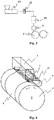
- FIG. 5 is a schematic diagram of part of a production device for general polymer sheets.
- Fig. 6 is an enlarged view of a casting step part of a conventional sheet production device.
- resin is melted and kneaded in an extruder 10, extruded into the shape of a sheet through a mouthpiece 1, and then pulled over a cast cooling device 2 to be cooled and solidified, as shown in Fig. 6 .
- the sheet production method of the present invention to solve the aforementioned problem is a sheet production method for producing a sheet using the sheet production device of the present invention.
- the air in the pressure-reducing section is sucked from the opening of the pressure-reducing chamber 4, and the air in the adhering portion between the sheet and the cast cooling device 2 is expelled. This causes the pressure in the adhering portion to be reduced, and the air entrained between the sheet and the cast cooling device 2 is expelled.
- controlling the level of pressure reduction to a predetermined pressure allows the sheet 3 composed of molten resin to adhere to the cast cooling device 2 in a stable manner.
- This pressure-reducing chamber constitutes an adhering means.
- the present embodiment includes rectification plates disposed downstream of the lip of the mouthpiece 1 in the conveying direction of the cast cooling device 2, and at positions more external than both end positions in the sheet width direction of the sheet 3 discharged from the mouthpiece 1, wherein the rectification plates are disposed at both ends of the mouthpiece in the width direction such that gaps between the sheet 3 discharged from the mouthpiece 1 and the cast cooling device 2 are occluded.
- the rectification plate 5 is mounted, being adhered and secured with bolts, to an adjusting mechanism enabling push and pull.
- screw holes are provided in the side plates of the mouthpiece 1.
- an elastic seal member is provided between the mouthpiece 1 and the pressure-reducing chamber 4, and this elastic seal member seals the gap between the mouthpiece 1 and the pressure-reducing chamber 4. Further, an elastic seal member is also provided between the cast cooling device 2 and the pressure-reducing chamber 4 in a similar manner, sealing the gap between the cast cooling device 2 and the pressure-reducing chamber 4.
- a constant distance L in the sheet width direction between any position of the end of the sheet 3 in the width direction and the rectification plate 5 keeps constant the flow velocity of air flowing in from the rectification plate 5 and the end of the sheet 3, whereby the effect of suppressing film vibration can further be obtained.
- the end on the upstream side of the rectification plate in the sheet conveying direction be disposed so as to be linked to the extension of the side plate 4b of the pressure-reducing chamber, whereby the air flowing in from the joint between the rectification plate and the pressure-reducing chamber can be suppressed to a minimum.
- the distance L has been mentioned as "constant"
- the distance to the rectification plate 5 does not have to be strictly the same value and allows an error of ⁇ 10%, as measured at any position of the end of the sheet in the width direction.
- a sheet was produced based on the same production conditions as in Example 1 except that the rectification plate was removed from the sheet production device of Example 1.
Landscapes
- Engineering & Computer Science (AREA)
- Mechanical Engineering (AREA)
- Physics & Mathematics (AREA)
- Thermal Sciences (AREA)
- Manufacturing & Machinery (AREA)
- Extrusion Moulding Of Plastics Or The Like (AREA)
Abstract
Description
- The present invention relates to a sheet production device and a sheet production method.
- A conventional sheet production device will be outlined with reference to the drawings.
Fig. 5 is a schematic diagram of part of a production device for general polymer sheets.Fig. 6 is an enlarged view of a casting step part of a conventional sheet production device. In a conventional sheet production device, resin is melted and kneaded in anextruder 10, extruded into the shape of a sheet through amouthpiece 1, and then pulled over acast cooling device 2 to be cooled and solidified, as shown inFig. 6 . Provided behind themouthpiece 1, in other words, upstream of the catching position for asheet 3 on the cast surface in the sheet conveying direction, is a pressure-reducingchamber 4 which is adjacent to themouthpiece 1 and is shaped along the outer periphery of thecast cooling device 2. This pressure-reducingchamber 4 generates a negative-pressure region at the back side of thesheet 3, in other words, at the side in contact with thecast cooling device 2. When thesheet 3 is pulled over thecast cooling device 2, the air in the pressure-reducingchamber 4 is sucked through a suction port and a duct hose, whereby the pressure of the space between thesheet 3 and thecast cooling device 2 is reduced through the opening of the pressure-reducingchamber 4. This evacuates the air flowing in between thesheet 3 and thecast cooling device 2, and allows the sheet composed of molten resin to adhere to thecast cooling device 2. Further, external air is sucked at the ends of the pressure-reducingchamber 4, causing a peculiar vortex thereat, and this is whyrectification plates 5 which regulate the flow of the air flowing in from the mouthpiece ends in the sheet width direction are provided at the ends of themouthpiece 1 in the sheet width direction, thereby allowing the sheet to adhere in a more stable manner. (Patent Literature 1) - Patent Literature 1:
JP 2000-225627 A - However, when the air between the sheet and the
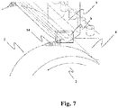
cast cooling device 2 is sucked by the pressure-reducingchamber 4, the air flow between the sheet and thecast cooling device 2 is not uniform, and air flows in from different directions, so that the air flow is remarkably prone to cause turbulence. On that account, controlling the air flow at the sheet ends is an important point in forming the sheet in a stable manner. However, if the distance (clearance) between the mouthpiece and the cast cooling device surface is wide at the sheet ends as shown inFig. 7 , an increase in distance (clearance) between the sheet and thecast cooling device 2 and the accompanying neck-in increase cause an increase in thegap 14, hence making it more difficult to rectify the air flow. On that account, vibrations still occur at the ends of the sheet, causing surface roughnesses such as lateral irregularities, creases, and the like to the sheet during the formation thereof. - In view of the aforementioned problem, the present invention provides a sheet production device and a sheet production method which can rectify air flow at the sheet ends and can thereby stabilize the formation of a sheet.
- The sheet production device of the present invention to solve the aforementioned problem is as follows: a sheet production device including: a mouthpiece for discharging molten resin in the shape of a sheet; a cast cooling device for cooling and solidifying the sheet discharged from the mouthpiece while conveying the sheet; and a pressure-reducing chamber disposed upstream of the mouthpiece in the conveying direction of the cast cooling device for sucking air from between the sheet discharged from the mouthpiece and the cast cooling device; and further including: two rectification plates disposed downstream of a lip of the mouthpiece in the conveying direction of the cast cooling device and at positions more external than the end positions in the width direction of the sheet discharged from the mouthpiece, wherein the rectification plates are disposed such that a gap between the sheet discharged from the mouthpiece and the cast cooling device is occluded; wherein a distance between the two rectification plates in the sheet width direction gradually decreases toward downstream of the cast cooling device in the conveying direction.
- The sheet production method of the present invention to solve the aforementioned problem is a sheet production method for producing a sheet using the sheet production device of the present invention.
- Examples of "resin" that can be used in the present invention include fluids made by dissolving in a diluent or melting the following: polyolefin resins such as polyethylene, polypropylene, polystyrene, and polymethylpentene; alicyclic polyolefin resins; polyamide resins such as nylon 6 and nylon 66; aramid resins; polyester resins such as polyethylene terephthalate, polybutylene terephthalate, polypropylene terephthalate, polybutyl succinate, and polyethylene-2,6-naphthalate; polycarbonate resins; polyalylate resins; polyacetal resins; polyphenylene sulfide resins; fluorine resins such as tetrafluoroethylene resin, trifluoroethylene resin, chlorotrifluoroethylene resin, tetrafluoroethylene-hexafluoropropylene copolymer, and vinylidene fluoride resin; acryl resins; methacryl resins; polyacetal resins; polyglycolic acid resins; polylactic acid resins; and the like. In addition, the use of a diluent including a liquid film-forming solvent makes it possible that it is not very difficult to stretch at a relatively high multiplying factor. These thermoplastic resins may be homo resins or may be copolymers or blends of two kinds or more. "Diluents" may be, for example, aliphatic, alicyclic, or aromatic hydrocarbons such as nonane, decane, decalin, p-xylene, undecane, and dodecene; liquid paraffins; mineral oil distillates having a boiling point similar to that of the aforementioned hydrocarbons; phthalate esters which are liquids at room temperature, such as dibutyl phthalate and dioctyl phthalate; and the like. In addition, various additives, for example, antioxidants, antistatic agents, nucleating agents, inorganic particles, organic particles, viscosity reducing agents, heat stabilizers, lubricants, infrared absorbers, ultraviolet absorbers, dopants for regulating refractive indices, and the like may be added to each thermoplastic resin.
- As used herein, the term "lip" refers to a slit opening through which to extrude molten resin in the shape of a sheet from the mouthpiece. As used herein, "longitudinal" refers to the longitudinal direction of a sheet, "width direction" refers to the width direction of a sheet, "upstream" refers to the upstream side in the conveying direction of a cast sheet, and "downstream" refers to the downstream side in the conveying direction of a cast sheet. As used herein, "heat-resistant temperature" refers to a use safety heat-resistant temperature which enables continuous use. As used herein, "lateral irregularity" refers to thickness unevenness periodically occurring in the sheet conveying direction on the surface of a sheet over the cast cooling device because a sheet discharged from the mouthpiece undergoes air vibration due to the influence on the ambient air flow by the suction in the pressure-reducing chamber before the sheet catches on the cast cooling device. Advantageous Effects of Invention
- According to the present invention, the flow of air flowing in through the gap between the sheet discharged from the mouthpiece and the cast cooling device can be rectified in the suction by the pressure-reducing chamber at the adherent portion between the sheet and the cast cooling device. As a result, the sheet discharged from the mouthpiece can be casted over the cast cooling device surface in a stable manner.
-
-
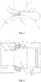
Fig. 1 is a schematic view of an embodiment of the sheet production device of the present invention. -
Fig. 2 is an enlarged view of the sheet production device ofFig. 1 . -
Fig. 3 is a side view of the sheet production device ofFig. 1 . -
Fig. 4 is a top view of the sheet production device ofFig. 1 . -
Fig. 5 is a schematic diagram illustrating a production device for polymer sheets. -
Fig. 6 is a schematic view of a conventional sheet production device. -
Fig. 7 is an enlarged view of the sheet production device ofFig. 6 . - Below, the embodiment will be described in detail, but the present invention is not to be limited to the embodiment including the below-mentioned Examples.
-
Fig. 1 is a schematic cross-sectional view of a sheet casting device which is an embodiment of the present invention. As illustrated inFig. 1 , the device includes amouthpiece 1 from which resin melted in an extruder is discharged in the shape of a sheet and acast cooling device 2 for cooling and solidifying asheet 3 discharged from themouthpiece 1 while pulling and conveying the sheet, and the discharged sheet is cast over the cast cooling device surface which is running. For this, the cast cooling device may be a roll or a belt. - Provided behind the
mouthpiece 1, in other words, upstream of the catching position for thesheet 3 on the cast surface in the sheet conveying direction, is a pressure-reducingchamber 4 which is adjacent to themouthpiece 1 and is shaped along the outer periphery of thecast cooling device 2. This pressure-reducingchamber 4 generates a negative-pressure region at the back side of thesheet 3, in other words, at the side in contact with thecast cooling device 2. The pressure-reducingchamber 4 has an opening and a pressure-reducing section, and the opening is formed over the full width of the sheet immediately near the portion at which thesheet 3 starts adhering to the outer periphery of thecast cooling device 2. In addition, the air in the pressure-reducing section is sucked from the opening of the pressure-reducingchamber 4, and the air in the adhering portion between the sheet and thecast cooling device 2 is expelled. This causes the pressure in the adhering portion to be reduced, and the air entrained between the sheet and thecast cooling device 2 is expelled. In addition, controlling the level of pressure reduction to a predetermined pressure allows thesheet 3 composed of molten resin to adhere to thecast cooling device 2 in a stable manner. This pressure-reducing chamber constitutes an adhering means. - During this, it is preferable that the level of pressure reduction in the pressure-reducing
chamber 4 be controlled to a predetermined value in accordance with the film-production conditions such as the viscosity of a molten polymer, the thickness of a sheet, and the sheet conveying rate of the cast cooling device. The suction pressure in the pressure-reducingchamber 4 relative to the atmospheric pressure is preferably in the range of -2500 Pa to -20 Pa. The lower limit of the suction pressure in the pressure-reducingchamber 4 relative to the atmospheric pressure is more preferably -1500 Pa or more, and the upper limit is further preferably -50 Pa or less. -
Fig. 2 is an enlarged view illustrating a configuration and a mounting state of the pressure-reducing chamber in the present invention. In addition,Fig. 3 is a side view ofFig. 2 , andFig. 4 is a top view ofFig. 2 . - As shown in
Fig. 2 to 4 , the present embodiment includes rectification plates disposed downstream of the lip of themouthpiece 1 in the conveying direction of thecast cooling device 2, and at positions more external than both end positions in the sheet width direction of thesheet 3 discharged from themouthpiece 1, wherein the rectification plates are disposed at both ends of the mouthpiece in the width direction such that gaps between thesheet 3 discharged from themouthpiece 1 and thecast cooling device 2 are occluded. Therectification plate 5 is mounted, being adhered and secured with bolts, to an adjusting mechanism enabling push and pull. In addition, screw holes are provided in the side plates of themouthpiece 1. Therectification plate 5 is held by the bracket 6, which is mounted to themouthpiece 1 with bolts passed through the holes provided in the bracket 6 and tightened into the screw holes of the mouthpiece side plate. This mounting method is one example only, and methods different from this mounting method may be used. For example, the bracket 6 may be mounted to the pressure-reducing chamber itself. Alternatively, the bracket may be configured to be integrated with the pressure-reducingchamber 4 or themouthpiece 1. - As shown in
Fig. 4 , the adjusting mechanism involves push and pull performed through the rotation of the positioning bolts 7, and has a joint for preventing corotation between the tip plate secured to therectification plate 5 by adhesion or bolting and the positioning bolts 7. By using these positioning bolts 7 to cause the opposite surface of therectification plate 5 from the side facing the sheet end to be pushed and pulled in the sheet width direction, the surface figure of the side of therectification plate 5 which faces the sheet end can be changed. The adjusting mechanism preferably causes the surface of the side of therectification plate 5 which faces the sheet end to be bent at least two points or more along thecast cooling device 2 in the conveying direction in accordance with the number of the flexion points in the neck-in of the sheet. In addition, an elastic seal member is provided between themouthpiece 1 and the pressure-reducingchamber 4, and this elastic seal member seals the gap between themouthpiece 1 and the pressure-reducingchamber 4. Further, an elastic seal member is also provided between thecast cooling device 2 and the pressure-reducingchamber 4 in a similar manner, sealing the gap between thecast cooling device 2 and the pressure-reducingchamber 4. - The configuration of the
rectification plate 5 of the present embodiment will be described. The distance in the sheet width direction between the rectification plates disposed at both ends of the mouthpiece in the width direction decreases gradually toward downstream of thecast cooling device 2 in the conveying direction, and the distance L in the sheet width direction between any position of the end in the width direction of thesheet 3 discharged from themouthpiece 1 and therectification plate 5 is constant. This allows the neck-in shape at the ends of thesheet 3 discharged from themouthpiece 1 to be followed. In particular, a constant distance L in the sheet width direction between any position of the end of thesheet 3 in the width direction and therectification plate 5 keeps constant the flow velocity of air flowing in from therectification plate 5 and the end of thesheet 3, whereby the effect of suppressing film vibration can further be obtained. In addition, as illustrated inFig. 4 , it is preferable that the end on the upstream side of the rectification plate in the sheet conveying direction be disposed so as to be linked to the extension of the side plate 4b of the pressure-reducing chamber, whereby the air flowing in from the joint between the rectification plate and the pressure-reducing chamber can be suppressed to a minimum. In this regard, although the distance L has been mentioned as "constant", the distance to therectification plate 5 does not have to be strictly the same value and allows an error of ±10%, as measured at any position of the end of the sheet in the width direction. - The distance L in the sheet width direction between any position of the end of the
sheet 3 in the width direction and therectification plate 5 is preferably 50 mm or less in view of preventing the turbulence of a direction of the air flowing from the sheet end, reducing the flopping of the sheet, and thereby suppressing the occurrence of surface roughnesses such as lateral irregularities and of creases. On that account, the distance L is ideally 0 mm, and it is preferable to reduce the pressure in the pressure-reducingchamber 4 in a stable manner by having a high degree of seal. In this case, however, the sheet end comes into contact with the rectification plate, because of which it is preferable, in view of inhibiting the sticking of the sheet to the rectification plate, to use a material having a high slipperiness such as a Teflon® sheet as a material for the rectification plate. More preferably, the distance L is set to 0.1 to 50 mm in order to prevent the sheet end from coming into contact with the rectification plate and secure the stability of the formability of the sheet end. The upper limit of the distance L is more preferably 10 mm or less to inhibit the flopping of the sheet further. In addition, as long as the distance L is in the aforementioned range, the surface figure of the side of therectification plate 5 which faces the sheet end may be shaped along the sheet end or planar. - The surface figure of the side of the
rectification plate 5 which faces the sheet end may be varied along the sheet conveying direction of thecast cooling device 2. In the present embodiment, the rectification plate in whole is curved along the shape of the sheet end, but the rectification plate does not necessarily have to be curved in whole. As long as only the surface figure of the side of therectification plate 5 which faces the sheet end can be varied so as to follow the shape of the sheet end, it is sufficient. - A material for the
rectification plate 5 is preferably at least one kind selected from the group consisting of rubber, metal, resin, paper, and wood, and is more preferably rubber. - When rubber is used as a material for the
rectification plate 5, the rubber preferably has a JIS A hardness of less than 80 degrees and a degree of elongation of 130% or more. The use of rubber having such a hardness and degree of elongation causes the rigidity to maintain the shape as a plate and makes it easy for the surface figure of the side of thisrectification plate 5 which faces the sheet end to be varied along the sheet end. In addition, the heat-resistant temperature of rubber is preferably 150°C or more. When the heat-resistant temperature is 150°C or more, the material can be prevented from being deteriorated by the heat received from the surrounding high temperature portion such as the mouthpiece. - The results from producing a sheet using the aforementioned sheet production device will be described. The configuration and production conditions of a specific sheet production device in the present embodiment are as follows:
- (1) Sheet material:
- High density polyethylene (HDPE), viscosity 1000 Pa.s. Here, the viscosity was measured in accordance with the method in JIS K7117-2 under the conditions of a shear rate of 100/s and a temperature of 200°C.
- (2) Charge stock:
- The sheet material was dried, then fed into the extruder, passed through the gear pump and the filter, and then fed into the sheet-forming mouthpiece. In addition, the device temperature up to the mouthpiece was set to 200°C.
- (3) Sheet-forming mouthpiece:
- The slit 300 mm in width, through which the resin was discharged at a flow rate of 250 kg/hr.
- (4) Cast cooling device:
- Using a sheet-forming roll as a cast cooling device, the material was extruded in the shape of a sheet through the sheet-forming mouthpiece, followed by formation on the cooling roll with the roll temperature set to 35°C.
- (5) Pressure-reducing chamber:
- The pressure-reducing chamber was installed with a clearance of 40 mm between the sheet-forming mouthpiece and the sheet-forming roll and with the lip of the mouthpiece positioned at the top of the roll. In addition, the distance L in the sheet width direction between any position of the end of the sheet and the rectification plate was adjusted to 50 mm. Further, the rectification plate was based on JIS K6251, and silicon rubber having a Shore A hardness of 75, an elongation of 400%, and a heat-resistant temperature of 200°C was used. The level of pressure reduction was set so as to be -1200 Pa relative to the atmospheric pressure.
- As a result of performing film-production, a stable operating condition was obtained on the cast surface of the sheet, and a sheet having a favorable quality was obtained, having a thickness unevenness R of 2.5% and no appearance defect due to film vibration, such as lateral irregularities.
Here, "thickness unevenness R" refers to a ratio resulting from subtracting a minimum sheet thickness from a maximum sheet thickness in the sheet conveying direction and then dividing the difference by the average sheet thickness. - A sheet was produced using the same sheet production device as in Example 1 except that silicon rubber for the rectification plate had a Shore A hardness of 50, an elongation of 330%, and a heat-resistant temperature of 150°C, and based on the same production conditions as in Example 1 except that the distance L in the sheet width direction between any position of the end of the sheet and the rectification plate was adjusted so as to be 10mm. As a result of performing film-production, a stable operating condition was obtained on the cast surface of the sheet, and a sheet having a favorable quality was obtained, having a thickness unevenness R of 1.0% and no appearance defect due to film vibration, such as lateral irregularities.
- A sheet was produced based on the same production conditions as in Example 1 except that the rectification plate was removed from the sheet production device of Example 1.
- As a result of performing film-production, a large film vibration occurred at the ends of the sheet between the mouthpiece and the cast surface, the thickness unevenness R was large at 10%, lateral irregularities having a pitch in the sheet conveying direction on the sheet in whole were seen, and thus the sheet could not be produced in a stable manner.
- The present invention can be applied to not only a sheet casting device but also a die coating device and the like, and the applicable scope is not to be limited to these.
-
- 1
- mouthpiece
- 2
- cast cooling device
- 3
- sheet
- 4
- pressure-reducing chamber
- 4a
- top plate
- 4b
- side plate
- 5
- rectification plate
- 6
- bracket
- 7
- positioning bolt
- 8
- distance L from sheet end to rectification plate in the sheet width direction
- 9
- mouthpiece lip
- 10
- extruder
- 11
- gear pump
- 12
- filter
- 13
- barrier
- 14
- gap between sheet and cast cooling device
Claims (8)
- A sheet production device comprising:a mouthpiece for discharging molten resin in the shape of a sheet;a cast cooling device for cooling and solidifying the sheet discharged from the mouthpiece while conveying the sheet; anda pressure-reducing chamber disposed upstream of the mouthpiece in the conveying direction of the cast cooling device for sucking air from between the sheet discharged from the mouthpiece and the cast cooling device;and further comprising: two rectification plates disposed downstream of a lip of the mouthpiece in the conveying direction of the cast cooling device and at positions more external than the end positions in the width direction of the sheet discharged from the mouthpiece, wherein the rectification plates are disposed such that a gap between the sheet discharged from the mouthpiece and the cast surface is occluded;wherein a distance between the two rectification plates in the sheet width direction gradually decreases toward downstream of the cast cooling device in the conveying direction.
- The sheet production device according to claim 1, comprising a mechanism wherein, by pushing or pulling the opposite surface from the side of the rectification plate which faces the end of the sheet in the width direction, the figure of the side of the rectification plate which faces the end of the sheet in the width direction is changed.
- The sheet production device according to claim 1 or 2, wherein a material for the rectification plate is at least one kind selected from the group consisting of rubber, metal, resin, paper, and wood.
- The sheet production device according to claim 3, wherein the material for the rectification plate is rubber and the rubber has a JIS hardness A of less than 80 degrees and a degree of elongation of 130% or more.
- The sheet production device according to claim 3 or 4, wherein the material for the rectification plate is rubber and the rubber has a heat-resistant temperature of 150°C or more.
- A sheet production method using the sheet production device according to any one of claims 1 to 5.
- The sheet production method according to claim 6, wherein a distance L in the sheet width direction between any position of the end in the width direction of the sheet discharged from the mouthpiece and the rectification plate is constant.
- The sheet production method according to claim 7, wherein the distance L is in the range of 0.1 to 50 mm.
Applications Claiming Priority (2)
| Application Number | Priority Date | Filing Date | Title |
|---|---|---|---|
| JP2015019865 | 2015-02-04 | ||
| PCT/JP2016/050397 WO2016125527A1 (en) | 2015-02-04 | 2016-01-07 | Sheet production device and sheet production method |
Publications (3)
| Publication Number | Publication Date |
|---|---|
| EP3254824A1 true EP3254824A1 (en) | 2017-12-13 |
| EP3254824A4 EP3254824A4 (en) | 2018-10-10 |
| EP3254824B1 EP3254824B1 (en) | 2021-10-06 |
Family
ID=56563878
Family Applications (1)
| Application Number | Title | Priority Date | Filing Date |
|---|---|---|---|
| EP16746358.7A Active EP3254824B1 (en) | 2015-02-04 | 2016-01-07 | Sheet production device and sheet production method |
Country Status (6)
| Country | Link |
|---|---|
| EP (1) | EP3254824B1 (en) |
| JP (1) | JP6047265B1 (en) |
| KR (1) | KR102357539B1 (en) |
| CN (1) | CN107206657A (en) |
| HU (1) | HUE057230T2 (en) |
| WO (1) | WO2016125527A1 (en) |
Families Citing this family (1)
| Publication number | Priority date | Publication date | Assignee | Title |
|---|---|---|---|---|
| EP4289611B1 (en) * | 2021-02-08 | 2025-04-23 | Toray Industries, Inc. | Method for manufacturing microporous polyolefin resin sheet and device for manufacturing microporous polyolefin resin sheet |
Family Cites Families (13)
| Publication number | Priority date | Publication date | Assignee | Title |
|---|---|---|---|---|
| JP2582401Y2 (en) * | 1993-03-25 | 1998-10-08 | 信越ポリマー株式会社 | Film deposition equipment |
| US5618568A (en) * | 1995-02-01 | 1997-04-08 | Extrusion Dies, Inc. | Dual-chamber vacuum box |
| JP3349388B2 (en) * | 1996-10-28 | 2002-11-25 | 三菱重工業株式会社 | Casting equipment for resin thin film molding |
| ID20180A (en) * | 1997-04-21 | 1998-10-22 | Mitsubishi Heavy Ind Ltd | PRINTING EQUIPMENT FOR THE FORMATION OF MEMBRANE MADE FROM RESIN |
| JP2000043122A (en) * | 1998-07-31 | 2000-02-15 | Teijin Ltd | Method of forming polymer sheet |
| JP2000225627A (en) | 1999-02-08 | 2000-08-15 | Toray Ind Inc | Film production equipment |
| JP2001026044A (en) * | 1999-07-14 | 2001-01-30 | Toray Ind Inc | Method for producing thermoplastic resin film |
| JP2001079924A (en) * | 1999-09-10 | 2001-03-27 | Mitsui Chemicals Inc | Extrusion molding t-die equipped with neck-in control mechanism |
| JP4464582B2 (en) * | 2001-05-30 | 2010-05-19 | 株式会社日本製鋼所 | Resin sheet manufacturing method and resin sheet molding casting apparatus |
| JP5173476B2 (en) * | 2007-12-05 | 2013-04-03 | 富士フイルム株式会社 | Thermoplastic resin film production equipment |
| WO2010140310A1 (en) * | 2009-06-04 | 2010-12-09 | 三菱エンジニアリングプラスチックス株式会社 | Resin extrusion die and extrusion method using same |
| WO2012026416A1 (en) * | 2010-08-24 | 2012-03-01 | コニカミノルタオプト株式会社 | Device for production of optical film |
| JP5660907B2 (en) * | 2011-01-25 | 2015-01-28 | 富士フイルム株式会社 | Decompression chamber, casting film forming method, and solution casting method |
-
2016
- 2016-01-07 EP EP16746358.7A patent/EP3254824B1/en active Active
- 2016-01-07 JP JP2016533219A patent/JP6047265B1/en active Active
- 2016-01-07 WO PCT/JP2016/050397 patent/WO2016125527A1/en not_active Ceased
- 2016-01-07 CN CN201680006790.1A patent/CN107206657A/en active Pending
- 2016-01-07 HU HUE16746358A patent/HUE057230T2/en unknown
- 2016-01-07 KR KR1020177021567A patent/KR102357539B1/en active Active
Also Published As
| Publication number | Publication date |
|---|---|
| WO2016125527A1 (en) | 2016-08-11 |
| JP6047265B1 (en) | 2016-12-21 |
| HUE057230T2 (en) | 2022-04-28 |
| JPWO2016125527A1 (en) | 2017-04-27 |
| KR102357539B1 (en) | 2022-02-03 |
| EP3254824B1 (en) | 2021-10-06 |
| CN107206657A (en) | 2017-09-26 |
| EP3254824A4 (en) | 2018-10-10 |
| KR20170117401A (en) | 2017-10-23 |
Similar Documents
| Publication | Publication Date | Title |
|---|---|---|
| JP6047264B1 (en) | Manufacturing apparatus and manufacturing method of microporous polyolefin resin sheet | |
| WO2012015593A1 (en) | Systems and methods for dispensing a fluid | |
| EP3254824A1 (en) | Sheet production device and sheet production method | |
| CN106660253B (en) | The manufacture device and manufacture method of micro- porous polyolefin resin flake | |
| US20220204851A1 (en) | Liquid crystal polymer film and substrate for high-speed communication | |
| US20230331983A1 (en) | Liquid crystal polymer film and substrate for high-speed communication | |
| US7867567B2 (en) | Coating method of coating solution | |
| US8092868B2 (en) | Die coating apparatus, die coating method, and adhesive sheet and foamed sheet | |
| US20120094070A1 (en) | Film for film capacitor | |
| JP5528980B2 (en) | Film manufacturing apparatus and manufacturing method | |
| WO2017047449A1 (en) | Coating device and coating method | |
| US8968860B2 (en) | Apparatus and process for producing laminated sheet | |
| JP6350117B2 (en) | Sheet forming die | |
| JPWO2018062028A1 (en) | Method for producing thermoplastic resin film | |
| JP7800418B2 (en) | Method for producing microporous polyolefin resin sheet and apparatus for producing microporous polyolefin resin sheet | |
| JP5508725B2 (en) | Method for extrusion molding of fluororesin film | |
| JP6326851B2 (en) | Sheet forming die and sheet forming method | |
| CN103144233B (en) | Extruding, casting molding defoamer of polyamide acid amine resin | |
| US20250145779A1 (en) | Process for the production of an ultra-high molecular weight polyethylene film by extrusion | |
| JP7635653B2 (en) | Sheet forming die | |
| JP2017217800A (en) | Lamination apparatus | |
| Kulikov et al. | IMPACT OF ELASTICITY ON EFFICIENCY OF PROCESSING ADDITIVES. NOVEL PROCESSING ADDITIVES BASED ON POLYOLS. | |
| JP2014012260A (en) | Coating device and coating method | |
| JP5400310B2 (en) | Coating apparatus and coating method | |
| JPS61272123A (en) | Manufacture of polyester film excellent in thickness accuracy |
Legal Events
| Date | Code | Title | Description |
|---|---|---|---|
| STAA | Information on the status of an ep patent application or granted ep patent |
Free format text: STATUS: THE INTERNATIONAL PUBLICATION HAS BEEN MADE |
|
| PUAI | Public reference made under article 153(3) epc to a published international application that has entered the european phase |
Free format text: ORIGINAL CODE: 0009012 |
|
| STAA | Information on the status of an ep patent application or granted ep patent |
Free format text: STATUS: REQUEST FOR EXAMINATION WAS MADE |
|
| 17P | Request for examination filed |
Effective date: 20170727 |
|
| AK | Designated contracting states |
Kind code of ref document: A1 Designated state(s): AL AT BE BG CH CY CZ DE DK EE ES FI FR GB GR HR HU IE IS IT LI LT LU LV MC MK MT NL NO PL PT RO RS SE SI SK SM TR |
|
| AX | Request for extension of the european patent |
Extension state: BA ME |
|
| DAV | Request for validation of the european patent (deleted) | ||
| DAX | Request for extension of the european patent (deleted) | ||
| A4 | Supplementary search report drawn up and despatched |
Effective date: 20180911 |
|
| RIC1 | Information provided on ipc code assigned before grant |
Ipc: B29C 47/88 20060101AFI20180905BHEP Ipc: B29C 47/14 20060101ALN20180905BHEP Ipc: B29C 47/08 20060101ALI20180905BHEP |
|
| REG | Reference to a national code |
Ref country code: DE Ref legal event code: R079 Ref document number: 602016064629 Country of ref document: DE Free format text: PREVIOUS MAIN CLASS: B29C0047880000 Ipc: B29C0048080000 |
|
| GRAP | Despatch of communication of intention to grant a patent |
Free format text: ORIGINAL CODE: EPIDOSNIGR1 |
|
| STAA | Information on the status of an ep patent application or granted ep patent |
Free format text: STATUS: GRANT OF PATENT IS INTENDED |
|
| RIC1 | Information provided on ipc code assigned before grant |
Ipc: B29C 48/08 20190101AFI20210517BHEP Ipc: B29C 48/88 20190101ALI20210517BHEP Ipc: B29C 48/255 20190101ALI20210517BHEP Ipc: B29C 48/305 20190101ALN20210517BHEP |
|
| INTG | Intention to grant announced |
Effective date: 20210604 |
|
| GRAS | Grant fee paid |
Free format text: ORIGINAL CODE: EPIDOSNIGR3 |
|
| GRAA | (expected) grant |
Free format text: ORIGINAL CODE: 0009210 |
|
| STAA | Information on the status of an ep patent application or granted ep patent |
Free format text: STATUS: THE PATENT HAS BEEN GRANTED |
|
| AK | Designated contracting states |
Kind code of ref document: B1 Designated state(s): AL AT BE BG CH CY CZ DE DK EE ES FI FR GB GR HR HU IE IS IT LI LT LU LV MC MK MT NL NO PL PT RO RS SE SI SK SM TR |
|
| REG | Reference to a national code |
Ref country code: GB Ref legal event code: FG4D |
|
| RIN1 | Information on inventor provided before grant (corrected) |
Inventor name: KIMISHIMA, KOTARO Inventor name: NOMURA, FUMIYASU Inventor name: MAKI, AKIHISA Inventor name: KITAMURA, OSAMU |
|
| REG | Reference to a national code |
Ref country code: CH Ref legal event code: EP Ref country code: AT Ref legal event code: REF Ref document number: 1435838 Country of ref document: AT Kind code of ref document: T Effective date: 20211015 |
|
| REG | Reference to a national code |
Ref country code: IE Ref legal event code: FG4D |
|
| REG | Reference to a national code |
Ref country code: DE Ref legal event code: R096 Ref document number: 602016064629 Country of ref document: DE |
|
| REG | Reference to a national code |
Ref country code: LT Ref legal event code: MG9D |
|
| REG | Reference to a national code |
Ref country code: NL Ref legal event code: MP Effective date: 20211006 |
|
| REG | Reference to a national code |
Ref country code: AT Ref legal event code: MK05 Ref document number: 1435838 Country of ref document: AT Kind code of ref document: T Effective date: 20211006 |
|
| REG | Reference to a national code |
Ref country code: HU Ref legal event code: AG4A Ref document number: E057230 Country of ref document: HU |
|
| PG25 | Lapsed in a contracting state [announced via postgrant information from national office to epo] |
Ref country code: RS Free format text: LAPSE BECAUSE OF FAILURE TO SUBMIT A TRANSLATION OF THE DESCRIPTION OR TO PAY THE FEE WITHIN THE PRESCRIBED TIME-LIMIT Effective date: 20211006 Ref country code: LT Free format text: LAPSE BECAUSE OF FAILURE TO SUBMIT A TRANSLATION OF THE DESCRIPTION OR TO PAY THE FEE WITHIN THE PRESCRIBED TIME-LIMIT Effective date: 20211006 Ref country code: FI Free format text: LAPSE BECAUSE OF FAILURE TO SUBMIT A TRANSLATION OF THE DESCRIPTION OR TO PAY THE FEE WITHIN THE PRESCRIBED TIME-LIMIT Effective date: 20211006 Ref country code: BG Free format text: LAPSE BECAUSE OF FAILURE TO SUBMIT A TRANSLATION OF THE DESCRIPTION OR TO PAY THE FEE WITHIN THE PRESCRIBED TIME-LIMIT Effective date: 20220106 Ref country code: AT Free format text: LAPSE BECAUSE OF FAILURE TO SUBMIT A TRANSLATION OF THE DESCRIPTION OR TO PAY THE FEE WITHIN THE PRESCRIBED TIME-LIMIT Effective date: 20211006 |
|
| PG25 | Lapsed in a contracting state [announced via postgrant information from national office to epo] |
Ref country code: IS Free format text: LAPSE BECAUSE OF FAILURE TO SUBMIT A TRANSLATION OF THE DESCRIPTION OR TO PAY THE FEE WITHIN THE PRESCRIBED TIME-LIMIT Effective date: 20220206 Ref country code: SE Free format text: LAPSE BECAUSE OF FAILURE TO SUBMIT A TRANSLATION OF THE DESCRIPTION OR TO PAY THE FEE WITHIN THE PRESCRIBED TIME-LIMIT Effective date: 20211006 Ref country code: PT Free format text: LAPSE BECAUSE OF FAILURE TO SUBMIT A TRANSLATION OF THE DESCRIPTION OR TO PAY THE FEE WITHIN THE PRESCRIBED TIME-LIMIT Effective date: 20220207 Ref country code: PL Free format text: LAPSE BECAUSE OF FAILURE TO SUBMIT A TRANSLATION OF THE DESCRIPTION OR TO PAY THE FEE WITHIN THE PRESCRIBED TIME-LIMIT Effective date: 20211006 Ref country code: NO Free format text: LAPSE BECAUSE OF FAILURE TO SUBMIT A TRANSLATION OF THE DESCRIPTION OR TO PAY THE FEE WITHIN THE PRESCRIBED TIME-LIMIT Effective date: 20220106 Ref country code: NL Free format text: LAPSE BECAUSE OF FAILURE TO SUBMIT A TRANSLATION OF THE DESCRIPTION OR TO PAY THE FEE WITHIN THE PRESCRIBED TIME-LIMIT Effective date: 20211006 Ref country code: LV Free format text: LAPSE BECAUSE OF FAILURE TO SUBMIT A TRANSLATION OF THE DESCRIPTION OR TO PAY THE FEE WITHIN THE PRESCRIBED TIME-LIMIT Effective date: 20211006 Ref country code: HR Free format text: LAPSE BECAUSE OF FAILURE TO SUBMIT A TRANSLATION OF THE DESCRIPTION OR TO PAY THE FEE WITHIN THE PRESCRIBED TIME-LIMIT Effective date: 20211006 Ref country code: GR Free format text: LAPSE BECAUSE OF FAILURE TO SUBMIT A TRANSLATION OF THE DESCRIPTION OR TO PAY THE FEE WITHIN THE PRESCRIBED TIME-LIMIT Effective date: 20220107 Ref country code: ES Free format text: LAPSE BECAUSE OF FAILURE TO SUBMIT A TRANSLATION OF THE DESCRIPTION OR TO PAY THE FEE WITHIN THE PRESCRIBED TIME-LIMIT Effective date: 20211006 |
|
| REG | Reference to a national code |
Ref country code: DE Ref legal event code: R097 Ref document number: 602016064629 Country of ref document: DE |
|
| PG25 | Lapsed in a contracting state [announced via postgrant information from national office to epo] |
Ref country code: SM Free format text: LAPSE BECAUSE OF FAILURE TO SUBMIT A TRANSLATION OF THE DESCRIPTION OR TO PAY THE FEE WITHIN THE PRESCRIBED TIME-LIMIT Effective date: 20211006 Ref country code: SK Free format text: LAPSE BECAUSE OF FAILURE TO SUBMIT A TRANSLATION OF THE DESCRIPTION OR TO PAY THE FEE WITHIN THE PRESCRIBED TIME-LIMIT Effective date: 20211006 Ref country code: RO Free format text: LAPSE BECAUSE OF FAILURE TO SUBMIT A TRANSLATION OF THE DESCRIPTION OR TO PAY THE FEE WITHIN THE PRESCRIBED TIME-LIMIT Effective date: 20211006 Ref country code: EE Free format text: LAPSE BECAUSE OF FAILURE TO SUBMIT A TRANSLATION OF THE DESCRIPTION OR TO PAY THE FEE WITHIN THE PRESCRIBED TIME-LIMIT Effective date: 20211006 Ref country code: DK Free format text: LAPSE BECAUSE OF FAILURE TO SUBMIT A TRANSLATION OF THE DESCRIPTION OR TO PAY THE FEE WITHIN THE PRESCRIBED TIME-LIMIT Effective date: 20211006 Ref country code: CZ Free format text: LAPSE BECAUSE OF FAILURE TO SUBMIT A TRANSLATION OF THE DESCRIPTION OR TO PAY THE FEE WITHIN THE PRESCRIBED TIME-LIMIT Effective date: 20211006 |
|
| REG | Reference to a national code |
Ref country code: DE Ref legal event code: R119 Ref document number: 602016064629 Country of ref document: DE |
|
| PLBE | No opposition filed within time limit |
Free format text: ORIGINAL CODE: 0009261 |
|
| STAA | Information on the status of an ep patent application or granted ep patent |
Free format text: STATUS: NO OPPOSITION FILED WITHIN TIME LIMIT |
|
| PG25 | Lapsed in a contracting state [announced via postgrant information from national office to epo] |
Ref country code: MC Free format text: LAPSE BECAUSE OF FAILURE TO SUBMIT A TRANSLATION OF THE DESCRIPTION OR TO PAY THE FEE WITHIN THE PRESCRIBED TIME-LIMIT Effective date: 20211006 |
|
| REG | Reference to a national code |
Ref country code: CH Ref legal event code: PL |
|
| 26N | No opposition filed |
Effective date: 20220707 |
|
| GBPC | Gb: european patent ceased through non-payment of renewal fee |
Effective date: 20220107 |
|
| REG | Reference to a national code |
Ref country code: BE Ref legal event code: MM Effective date: 20220131 |
|
| PG25 | Lapsed in a contracting state [announced via postgrant information from national office to epo] |
Ref country code: LU Free format text: LAPSE BECAUSE OF NON-PAYMENT OF DUE FEES Effective date: 20220107 Ref country code: GB Free format text: LAPSE BECAUSE OF NON-PAYMENT OF DUE FEES Effective date: 20220107 Ref country code: DE Free format text: LAPSE BECAUSE OF NON-PAYMENT OF DUE FEES Effective date: 20220802 Ref country code: AL Free format text: LAPSE BECAUSE OF FAILURE TO SUBMIT A TRANSLATION OF THE DESCRIPTION OR TO PAY THE FEE WITHIN THE PRESCRIBED TIME-LIMIT Effective date: 20211006 |
|
| PG25 | Lapsed in a contracting state [announced via postgrant information from national office to epo] |
Ref country code: SI Free format text: LAPSE BECAUSE OF FAILURE TO SUBMIT A TRANSLATION OF THE DESCRIPTION OR TO PAY THE FEE WITHIN THE PRESCRIBED TIME-LIMIT Effective date: 20211006 Ref country code: FR Free format text: LAPSE BECAUSE OF NON-PAYMENT OF DUE FEES Effective date: 20220131 Ref country code: BE Free format text: LAPSE BECAUSE OF NON-PAYMENT OF DUE FEES Effective date: 20220131 |
|
| PG25 | Lapsed in a contracting state [announced via postgrant information from national office to epo] |
Ref country code: LI Free format text: LAPSE BECAUSE OF NON-PAYMENT OF DUE FEES Effective date: 20220131 Ref country code: CH Free format text: LAPSE BECAUSE OF NON-PAYMENT OF DUE FEES Effective date: 20220131 |
|
| PG25 | Lapsed in a contracting state [announced via postgrant information from national office to epo] |
Ref country code: IE Free format text: LAPSE BECAUSE OF NON-PAYMENT OF DUE FEES Effective date: 20220107 |
|
| PG25 | Lapsed in a contracting state [announced via postgrant information from national office to epo] |
Ref country code: IT Free format text: LAPSE BECAUSE OF FAILURE TO SUBMIT A TRANSLATION OF THE DESCRIPTION OR TO PAY THE FEE WITHIN THE PRESCRIBED TIME-LIMIT Effective date: 20211006 |
|
| P01 | Opt-out of the competence of the unified patent court (upc) registered |
Effective date: 20230515 |
|
| PG25 | Lapsed in a contracting state [announced via postgrant information from national office to epo] |
Ref country code: MK Free format text: LAPSE BECAUSE OF FAILURE TO SUBMIT A TRANSLATION OF THE DESCRIPTION OR TO PAY THE FEE WITHIN THE PRESCRIBED TIME-LIMIT Effective date: 20211006 Ref country code: CY Free format text: LAPSE BECAUSE OF FAILURE TO SUBMIT A TRANSLATION OF THE DESCRIPTION OR TO PAY THE FEE WITHIN THE PRESCRIBED TIME-LIMIT Effective date: 20211006 |
|
| PG25 | Lapsed in a contracting state [announced via postgrant information from national office to epo] |
Ref country code: MT Free format text: LAPSE BECAUSE OF FAILURE TO SUBMIT A TRANSLATION OF THE DESCRIPTION OR TO PAY THE FEE WITHIN THE PRESCRIBED TIME-LIMIT Effective date: 20211006 |
|
| PG25 | Lapsed in a contracting state [announced via postgrant information from national office to epo] |
Ref country code: TR Free format text: LAPSE BECAUSE OF FAILURE TO SUBMIT A TRANSLATION OF THE DESCRIPTION OR TO PAY THE FEE WITHIN THE PRESCRIBED TIME-LIMIT Effective date: 20211006 |
|
| PGFP | Annual fee paid to national office [announced via postgrant information from national office to epo] |
Ref country code: HU Payment date: 20260112 Year of fee payment: 11 |