EP3253592B1 - Radial tyre having a very thin belt structure - Google Patents
Radial tyre having a very thin belt structure Download PDFInfo
- Publication number
- EP3253592B1 EP3253592B1 EP16701181.6A EP16701181A EP3253592B1 EP 3253592 B1 EP3253592 B1 EP 3253592B1 EP 16701181 A EP16701181 A EP 16701181A EP 3253592 B1 EP3253592 B1 EP 3253592B1
- Authority
- EP
- European Patent Office
- Prior art keywords
- reinforcers
- rubber
- tyre according
- reinforcements
- layer
- Prior art date
- Legal status (The legal status is an assumption and is not a legal conclusion. Google has not performed a legal analysis and makes no representation as to the accuracy of the status listed.)
- Active
Links
Images

Classifications
-
- B—PERFORMING OPERATIONS; TRANSPORTING
- B60—VEHICLES IN GENERAL
- B60C—VEHICLE TYRES; TYRE INFLATION; TYRE CHANGING; CONNECTING VALVES TO INFLATABLE ELASTIC BODIES IN GENERAL; DEVICES OR ARRANGEMENTS RELATED TO TYRES
- B60C9/00—Reinforcements or ply arrangement of pneumatic tyres
- B60C9/18—Structure or arrangement of belts or breakers, crown-reinforcing or cushioning layers
- B60C9/20—Structure or arrangement of belts or breakers, crown-reinforcing or cushioning layers built-up from rubberised plies each having all cords arranged substantially parallel
- B60C9/2003—Structure or arrangement of belts or breakers, crown-reinforcing or cushioning layers built-up from rubberised plies each having all cords arranged substantially parallel characterised by the materials of the belt cords
-
- B—PERFORMING OPERATIONS; TRANSPORTING
- B60—VEHICLES IN GENERAL
- B60C—VEHICLE TYRES; TYRE INFLATION; TYRE CHANGING; CONNECTING VALVES TO INFLATABLE ELASTIC BODIES IN GENERAL; DEVICES OR ARRANGEMENTS RELATED TO TYRES
- B60C9/00—Reinforcements or ply arrangement of pneumatic tyres
- B60C9/0042—Reinforcements made of synthetic materials
-
- B—PERFORMING OPERATIONS; TRANSPORTING
- B60—VEHICLES IN GENERAL
- B60C—VEHICLE TYRES; TYRE INFLATION; TYRE CHANGING; CONNECTING VALVES TO INFLATABLE ELASTIC BODIES IN GENERAL; DEVICES OR ARRANGEMENTS RELATED TO TYRES
- B60C9/00—Reinforcements or ply arrangement of pneumatic tyres
- B60C9/005—Reinforcements made of different materials, e.g. hybrid or composite cords
-
- B—PERFORMING OPERATIONS; TRANSPORTING
- B60—VEHICLES IN GENERAL
- B60C—VEHICLE TYRES; TYRE INFLATION; TYRE CHANGING; CONNECTING VALVES TO INFLATABLE ELASTIC BODIES IN GENERAL; DEVICES OR ARRANGEMENTS RELATED TO TYRES
- B60C9/00—Reinforcements or ply arrangement of pneumatic tyres
- B60C9/0064—Reinforcements comprising monofilaments
-
- B—PERFORMING OPERATIONS; TRANSPORTING
- B60—VEHICLES IN GENERAL
- B60C—VEHICLE TYRES; TYRE INFLATION; TYRE CHANGING; CONNECTING VALVES TO INFLATABLE ELASTIC BODIES IN GENERAL; DEVICES OR ARRANGEMENTS RELATED TO TYRES
- B60C9/00—Reinforcements or ply arrangement of pneumatic tyres
- B60C9/18—Structure or arrangement of belts or breakers, crown-reinforcing or cushioning layers
- B60C9/20—Structure or arrangement of belts or breakers, crown-reinforcing or cushioning layers built-up from rubberised plies each having all cords arranged substantially parallel
- B60C9/2003—Structure or arrangement of belts or breakers, crown-reinforcing or cushioning layers built-up from rubberised plies each having all cords arranged substantially parallel characterised by the materials of the belt cords
- B60C9/2009—Structure or arrangement of belts or breakers, crown-reinforcing or cushioning layers built-up from rubberised plies each having all cords arranged substantially parallel characterised by the materials of the belt cords comprising plies of different materials
-
- D—TEXTILES; PAPER
- D02—YARNS; MECHANICAL FINISHING OF YARNS OR ROPES; WARPING OR BEAMING
- D02G—CRIMPING OR CURLING FIBRES, FILAMENTS, THREADS, OR YARNS; YARNS OR THREADS
- D02G3/00—Yarns or threads, e.g. fancy yarns; Processes or apparatus for the production thereof, not otherwise provided for
- D02G3/44—Yarns or threads characterised by the purpose for which they are designed
- D02G3/48—Tyre cords
-
- B—PERFORMING OPERATIONS; TRANSPORTING
- B60—VEHICLES IN GENERAL
- B60C—VEHICLE TYRES; TYRE INFLATION; TYRE CHANGING; CONNECTING VALVES TO INFLATABLE ELASTIC BODIES IN GENERAL; DEVICES OR ARRANGEMENTS RELATED TO TYRES
- B60C9/00—Reinforcements or ply arrangement of pneumatic tyres
- B60C9/18—Structure or arrangement of belts or breakers, crown-reinforcing or cushioning layers
- B60C9/20—Structure or arrangement of belts or breakers, crown-reinforcing or cushioning layers built-up from rubberised plies each having all cords arranged substantially parallel
- B60C2009/2012—Structure or arrangement of belts or breakers, crown-reinforcing or cushioning layers built-up from rubberised plies each having all cords arranged substantially parallel with particular configuration of the belt cords in the respective belt layers
- B60C2009/2016—Structure or arrangement of belts or breakers, crown-reinforcing or cushioning layers built-up from rubberised plies each having all cords arranged substantially parallel with particular configuration of the belt cords in the respective belt layers comprising cords at an angle of 10 to 30 degrees to the circumferential direction
-
- B—PERFORMING OPERATIONS; TRANSPORTING
- B60—VEHICLES IN GENERAL
- B60C—VEHICLE TYRES; TYRE INFLATION; TYRE CHANGING; CONNECTING VALVES TO INFLATABLE ELASTIC BODIES IN GENERAL; DEVICES OR ARRANGEMENTS RELATED TO TYRES
- B60C9/00—Reinforcements or ply arrangement of pneumatic tyres
- B60C9/18—Structure or arrangement of belts or breakers, crown-reinforcing or cushioning layers
- B60C9/20—Structure or arrangement of belts or breakers, crown-reinforcing or cushioning layers built-up from rubberised plies each having all cords arranged substantially parallel
- B60C2009/2061—Physical properties or dimensions of the belt coating rubber
- B60C2009/2067—Thickness
-
- B—PERFORMING OPERATIONS; TRANSPORTING
- B60—VEHICLES IN GENERAL
- B60C—VEHICLE TYRES; TYRE INFLATION; TYRE CHANGING; CONNECTING VALVES TO INFLATABLE ELASTIC BODIES IN GENERAL; DEVICES OR ARRANGEMENTS RELATED TO TYRES
- B60C9/00—Reinforcements or ply arrangement of pneumatic tyres
- B60C9/18—Structure or arrangement of belts or breakers, crown-reinforcing or cushioning layers
- B60C9/20—Structure or arrangement of belts or breakers, crown-reinforcing or cushioning layers built-up from rubberised plies each having all cords arranged substantially parallel
- B60C2009/2074—Physical properties or dimension of the belt cord
- B60C2009/2077—Diameters of the cords; Linear density thereof
-
- B—PERFORMING OPERATIONS; TRANSPORTING
- B60—VEHICLES IN GENERAL
- B60C—VEHICLE TYRES; TYRE INFLATION; TYRE CHANGING; CONNECTING VALVES TO INFLATABLE ELASTIC BODIES IN GENERAL; DEVICES OR ARRANGEMENTS RELATED TO TYRES
- B60C9/00—Reinforcements or ply arrangement of pneumatic tyres
- B60C9/18—Structure or arrangement of belts or breakers, crown-reinforcing or cushioning layers
- B60C9/20—Structure or arrangement of belts or breakers, crown-reinforcing or cushioning layers built-up from rubberised plies each having all cords arranged substantially parallel
- B60C2009/2074—Physical properties or dimension of the belt cord
- B60C2009/2083—Density in width direction
-
- B—PERFORMING OPERATIONS; TRANSPORTING
- B60—VEHICLES IN GENERAL
- B60C—VEHICLE TYRES; TYRE INFLATION; TYRE CHANGING; CONNECTING VALVES TO INFLATABLE ELASTIC BODIES IN GENERAL; DEVICES OR ARRANGEMENTS RELATED TO TYRES
- B60C9/00—Reinforcements or ply arrangement of pneumatic tyres
- B60C9/18—Structure or arrangement of belts or breakers, crown-reinforcing or cushioning layers
- B60C9/20—Structure or arrangement of belts or breakers, crown-reinforcing or cushioning layers built-up from rubberised plies each having all cords arranged substantially parallel
- B60C2009/2074—Physical properties or dimension of the belt cord
- B60C2009/2096—Twist structures
-
- B—PERFORMING OPERATIONS; TRANSPORTING
- B60—VEHICLES IN GENERAL
- B60C—VEHICLE TYRES; TYRE INFLATION; TYRE CHANGING; CONNECTING VALVES TO INFLATABLE ELASTIC BODIES IN GENERAL; DEVICES OR ARRANGEMENTS RELATED TO TYRES
- B60C9/00—Reinforcements or ply arrangement of pneumatic tyres
- B60C9/18—Structure or arrangement of belts or breakers, crown-reinforcing or cushioning layers
- B60C9/20—Structure or arrangement of belts or breakers, crown-reinforcing or cushioning layers built-up from rubberised plies each having all cords arranged substantially parallel
- B60C9/22—Structure or arrangement of belts or breakers, crown-reinforcing or cushioning layers built-up from rubberised plies each having all cords arranged substantially parallel the plies being arranged with all cords disposed along the circumference of the tyre
- B60C2009/2252—Physical properties or dimension of the zero degree ply cords
- B60C2009/2257—Diameters of the cords; Linear density thereof
-
- D—TEXTILES; PAPER
- D10—INDEXING SCHEME ASSOCIATED WITH SUBLASSES OF SECTION D, RELATING TO TEXTILES
- D10B—INDEXING SCHEME ASSOCIATED WITH SUBLASSES OF SECTION D, RELATING TO TEXTILES
- D10B2331/00—Fibres made from polymers obtained otherwise than by reactions only involving carbon-to-carbon unsaturated bonds, e.g. polycondensation products
- D10B2331/02—Fibres made from polymers obtained otherwise than by reactions only involving carbon-to-carbon unsaturated bonds, e.g. polycondensation products polyamides
-
- D—TEXTILES; PAPER
- D10—INDEXING SCHEME ASSOCIATED WITH SUBLASSES OF SECTION D, RELATING TO TEXTILES
- D10B—INDEXING SCHEME ASSOCIATED WITH SUBLASSES OF SECTION D, RELATING TO TEXTILES
- D10B2331/00—Fibres made from polymers obtained otherwise than by reactions only involving carbon-to-carbon unsaturated bonds, e.g. polycondensation products
- D10B2331/04—Fibres made from polymers obtained otherwise than by reactions only involving carbon-to-carbon unsaturated bonds, e.g. polycondensation products polyesters, e.g. polyethylene terephthalate [PET]
Definitions
- the present invention relates to tires for vehicles, and to their crown or belt reinforcement. It relates more particularly to multilayer composite laminates used in the belt of such tires, in particular for passenger vehicle or van.
- a tire with a radial carcass reinforcement for a passenger vehicle or a van comprises, as is known, a tread, two inextensible beads, two flexible sidewalls connecting the beads to the tread and a rigid crown reinforcement or “belt” ( “ belt “ ) arranged circumferentially between the carcass reinforcement and the tread.
- the tire belt is generally made up of at least two plies of rubber known as “working plies”, “triangulation plies” or even “working armature”, superimposed and crossed, most often reinforced with metal cables arranged substantially parallel to one another. with respect to the others and inclined with respect to the median circumferential plane, these working plies may or may not be associated with other plies and / or rubber fabrics.
- the main function of these working plies is to give the tire a high rigidity or drift thrust (" drift thrust " or " cornering "), necessary in known manner for obtaining good road handling ( “handling " ) on a motor vehicle.
- the above belt which is particularly the case for tires capable of rolling at high speed in a sustained manner, may further comprise an additional rubber ply above the working plies (tread side), called " hooping ply “or” hooping reinforcement ", which is generally reinforced by so-called” circumferential "reinforcing threads, that is to say that these reinforcing threads are arranged practically parallel to one another and extend substantially circumferentially around the pneumatic envelope so as to form an angle preferably comprised in a range of -5 ° to + 5 ° with the median circumferential plane.
- These circumferential reinforcement wires have the primary function, it will be recalled, of resisting centrifugation of the crown at high speed.
- Such belt structures ultimately consisting of a multilayer composite laminate comprising at least one hooping ply, most often textile, and two generally metallic working plies, are well known to those skilled in the art and do not need to be described here in more detail.
- the first reinforcements preferably made of polyamide or polyester, consist of multifilament fibers comprising a very large number (typically several hundred) of elementary filaments of very small diameter, which are twisted together in the form of conventional textile cords.
- the second and third reinforcements for their part, consist of unitary steel monofilaments, in particular very high strength carbon steel.
- the weight of the tires and their rolling resistance can be reduced, at reduced cost thanks to the use of steel monofilaments which do not require any prior assembly operation, and this without penalizing the stiffness of drift or the overall endurance in rolling.
- the Applicants have developed an improved multilayer composite laminate, of new architecture, which addresses the above problem and which can therefore constitute an advantageous alternative to the laminates described in the two aforementioned applications, when it is desired to reduce the thicknesses of the rubber layers and consequently the rolling resistance of the tires.
- the multilayer composite laminate according to the invention can be used as a belt reinforcement element for any type of tire, particularly for passenger vehicles including in particular 4x4 and "SUV" vehicles ( Sport Utility Vehicles ) or for van vehicles.
- x and / or y means “x” or “y” or both (ie “x and y”). Any range of values designated by the expression “between a and b” represents the range of values going from more than “a” to less than “b” (ie limits "a” and “b” excluded ) while any range of values designated by the expression “from a to b” means the range of values going from “a” to "b” (that is to say including the strict limits "a” and “b” ).
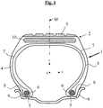
- the figure 1 very schematically (that is to say without respecting a specific scale) a radial section of a tire according to the invention, for example for a vehicle of the passenger or pickup type, the belt of which comprises a laminate multilayer composite according to the invention.
- This tire (1) defining three perpendicular, circumferential (X), axial (Y) and radial (Z) directions, has a crown (2) surmounted by a tread (3), two sidewalls (4), two beads (5), each side (4) connecting each bead (5) to the top (2), a carcass reinforcement (7) anchored in each of the beads (5) and extending in the sides ( 4) to the top (2), a top reinforcement or belt (10) extending in the top (2) in the circumferential direction (X) and located radially between the carcass reinforcement (7) and the strip bearing (3).
- the carcass reinforcement (7) is in known manner made up of at least one rubber ply reinforced by so-called "radial" textile cords, arranged practically parallel to one another and extending from one bead to the other so as to form an angle generally between 80 ° and 90 ° with the median circumferential plane M; it is here, for example, wound around two rods (6) in each bead (5), the reversal (8) of this frame (7) being for example disposed towards the outside of the tire (1) which is shown here mounted on its rim (9).
- angles ⁇ and ⁇ of opposite directions can be identical or different, that is to say that the second (120) and third (130) reinforcements can be arranged symmetrically or not, on either side of the previously defined median circumferential plane (M).
- the tread (3), the multilayer laminate (10) and the carcass reinforcement (7) may or may not be in contact with each other, even if these parts have been deliberately separated on the figure 1 , schematically, for reasons of simplification and clarity of the drawing. They could be physically separated, at least for part of them, for example by bonding gums, well known to those skilled in the art, intended to optimize the cohesion of the assembly after curing or crosslinking.
- the first reinforcements (110) of heat-shrinkable textile material are monofilaments or assemblies of monofilaments, such monofilaments taken individually having a diameter (or, by definition, a thickness if the monofilament does not not a substantially circular cross section) noted ⁇ which is greater than 0.10 mm, preferably between 0.15 and 0.80 mm, in particular between 0.20 and 0.60 mm.
- the overall diameter D1 of these first textile reinforcements (110) is between 0.20 mm and 1.20 mm, preferably between 0.30 and 1.00 mm, in particular between 0, 40 and 0.80 mm; in other words, in the particular case where the reinforcement (110) consists of a unitary textile monofilament of circular cross section, the latter has a diameter ⁇ which is necessarily greater than 0.20 mm.
- the usual denomination diameter is understood to mean the diameter of the imaginary cylinder of revolution which surrounds such first textile reinforcements (110) in the general case where the latter are not of circular cross section.
- Any heat-shrinkable textile material is suitable, in particular and preferably a textile material verifying the CT contraction characteristics set out below is suitable.
- this heat-shrinkable textile material is chosen from the group consisting of polyamides, polyesters and polyketones.
- polyamides mention may in particular be made of polyamides 4-6, 6, 6-6, 11 or 12.
- polyesters mention may, for example, be made of PET (polyethylene terephthalate), PEN (polyethylene naphthalate), PBT (polybutylene terephthalate) ), PBN (polybutylene naphthalate), PPT (polypropylene terephthalate), PPN (polypropylene naphthalate).
- hybrid reinforcements made up of two (at least two) different materials such as for example assemblies of aramid / nylon, aramid / polyester monofilaments , aramid / polyketone.
- the heat-shrinkable textile material constituting the first reinforcements (110) is a polyamide (nylon) or a polyester.
- the density d 1 of the first reinforcements (110) in the first rubber layer (C1), measured in the axial direction (Y), is preferably between 70 and 130 threads / dm, more preferably between 80 and 120 threads / dm, in particular between 90 and 110 threads / dm.
- Their thermal contraction (denoted CT), after 2 min at 185 ° C., is preferably less than 7.5%, more preferably less than 7.0%, in particular less than 6.0%, values which have been found to be preferable. for the manufacturing and dimensioning stability of tire casings, in particular during the curing and cooling phases thereof.
- the magnitude CT is measured, unless otherwise specified, according to standard ASTM D1204-08, for example on a device of the “TESTRITE” type, under a pretension known as standard of 0.5 cN / tex (therefore reduced to the titer or linear density of the tested sample).
- the maximum of the contraction force (denoted F C ) is also measured using the above test, this time at a temperature of 180 ° C. and under 3% elongation.
- This contraction force F C is preferably greater than 20 N (Newton).
- a high contraction force has been found to be particularly favorable to the hooping capacity of the first reinforcements (110) made of heat-shrinkable textile material, vis-à-vis the crown reinforcement of the tire when the latter heats up at high speed. of rolling.
- the sizes CT and F C above can be measured without distinction on the initial textile reinforcements glued before their incorporation in the laminate and then in the tire, or else measured on these reinforcements once extracted from the central zone of the vulcanized tire and preferably " degummed ”(that is to say, freed from the rubber which coats them in layer C1).
- the figure 4 shows diagrammatically in cross section, different examples (112, 113, 114, 115, 116, 117) of assemblies of (respectively 2, 3, 4, 5, 6 and 7) monofilaments (111) of heat-shrinkable textile material such as for example polyamide, polyester or polyketone, which can be used as reinforcements (110) in the first layer (10a) of the multilayer composite laminate according to the invention.
- monofilaments (111) of heat-shrinkable textile material such as for example polyamide, polyester or polyketone, which can be used as reinforcements (110) in the first layer (10a) of the multilayer composite laminate according to the invention.
- Heat-shrinkable textile monofilaments or assemblies of monofilaments have the advantage, compared to textile cords formed of conventional multifilament fibers, of better protecting against moisture the rest of the multilayer composite laminate, thus limiting the risks of penalizing the adhesion between the various reinforcements of the laminate and their surrounding rubber matrix, without taking into account the risks of surface corrosion of the steel mono filaments.
- assemblies of textile monofilaments preferably comprise 2 to 10, more preferably from 3 to 7 monofilaments made of heat-shrinkable textile material such as for example polyamide, polyester or polyketone.
- the monowires are wired, twisted together according to well known techniques, with a twist preferably between 30 and 200 rpm (turns per meter), more preferably between 30 and 100 rpm, these monowires being in known manner devoid, or almost devoid, of twist on themselves.
- the second (120) and third (130) reinforcements consist of steel monofilaments, which, as a reminder, are not twisted, wired together but used in the unitary state; their diameter (or by definition thickness if the monofilament does not have a circular cross section), respectively denoted D2 and D3, is between 0.20 mm and 0.50 mm.
- D2 and D3 may be the same or different from one layer to another; if they are different, D3 can be greater than D2 or even less than D2, according to the particular embodiments of the invention.
- D2 and D3 are greater than 0.25 mm and less than 0.40 mm, more preferably included in a range of 0.28 to 0.35 mm.
- the density, denoted respectively d 2 and d 3 , of the second (120) and third (130) reinforcements in the second (C2) and third (C3) layers of rubber respectively, measured in the axial direction (Y), is comprised of preferably between 100 and 180 threads / dm, more preferably between 110 and 170 threads / dm, in particular between 120 and 160 threads / dm.
- the steel of the monofilaments is a carbon steel such as those used in " steel cords" type cables for tires; but it is of course possible to use other steels, for example stainless steels, or other alloys.
- a carbon steel when a carbon steel is used, its carbon content (% by weight of steel) is within a range of 0.5% to 1.2%, more preferably 0.7 % to 1.0%.
- the invention applies in particular to steels of the steel cord type with normal resistance (called “NT” for “ Normal Tensile ”) or with high resistance (said “HT” for “High Tensile “), the (second and third ) carbon steel reinforcements then having a tensile strength (Rm) which is preferably greater than 2000 MPa, more preferably greater than 2500 MPa.
- the invention also applies to steels of the steel cord type with very high resistance (called “SHT” for " Super High Tensile "), ultra-high resistance (called “UHT” for “Ultra High Tensile “ or “MT” for “Mega Tensile “), the (second and third) carbon steel reinforcements then having a tensile strength (Rm) which is preferably greater than 3000 MPa, more preferably greater than 3500 MPa.
- Rm tensile strength
- the total elongation at break (At) of these reinforcements, the sum of the elastic elongation and the plastic elongation, is preferably greater than 2.0%.
- the steel used can itself be coated with a metallic layer improving, for example, the processing properties of the monofilament d steel, or the use properties of the reinforcement and / or of the tire themselves, such as the adhesion, corrosion resistance or even resistance to aging properties.
- the steel used is covered with a layer of brass (Zn-Cu alloy) or zinc; it is recalled that during the wire manufacturing process, the coating of brass or zinc facilitates the wire drawing, as well as the bonding of the wire with the rubber.
- the reinforcements could be covered with a thin metallic layer other than brass or zinc, having for example the function of improving the corrosion resistance of these wires and / or their adhesion to rubber, for example a thin layer of Co, Ni, Al, an alloy of two or more of the compounds Cu, Zn, Al, Ni, Co, Sn.
- a thin metallic layer other than brass or zinc having for example the function of improving the corrosion resistance of these wires and / or their adhesion to rubber, for example a thin layer of Co, Ni, Al, an alloy of two or more of the compounds Cu, Zn, Al, Ni, Co, Sn.
- Each layer (C1, C2, C3) of rubber composition (or hereinafter “rubber layer”) constituting the multilayer composite laminate is based on at least one elastomer and a filler.
- the rubber is a diene rubber, that is to say as a reminder any elastomer (single elastomer or mixture of elastomers) which is derived, at least in part (ie, a homopolymer or a copolymer), from monomers dienes, that is to say monomers carrying two carbon-carbon double bonds, whether the latter are conjugated or not.
- elastomer single elastomer or mixture of elastomers
- monomers dienes that is to say monomers carrying two carbon-carbon double bonds, whether the latter are conjugated or not.
- This diene elastomer is more preferably chosen from the group consisting of polybutadienes (BR), natural rubber (NR), synthetic polyisoprenes (IR), butadiene copolymers, isoprene copolymers, and mixtures of these elastomers , such copolymers being chosen in particular from the group consisting of butadiene-styrene copolymers (SBR), isoprene-butadiene copolymers (BIR), isoprene-styrene copolymers (SIR) and isoprene copolymers- butadiene-styrene (SBIR).
- SBR butadiene-styrene copolymers
- BIR isoprene-butadiene copolymers
- SIR isoprene-styrene copolymers
- SBIR isoprene copolymers- butadiene-styrene
- a particularly preferred embodiment consists in using an “isoprene” elastomer, that is to say a homopolymer or a copolymer of isoprene, in other words a diene elastomer chosen from the group consisting of natural rubber (NR ), synthetic polyisoprenes (IR), the various isoprene copolymers and mixtures of these elastomers.
- isoprene elastomer
- NR natural rubber
- IR synthetic polyisoprenes
- the isoprene elastomer is preferably natural rubber or a synthetic polyisoprene of the cis-1,4 type.
- polyisoprenes are preferably used having a rate (mol%) of cis-1,4 bonds greater than 90%, more preferably still greater than 98%.
- each layer of rubber composition comprises 50 to 100 phr of natural rubber.
- the diene elastomer may consist, in whole or in part, of another diene elastomer such as, for example, an SBR elastomer used in combination or not with another elastomer, for example type BR.
- Each rubber composition can comprise one or more diene elastomer (s), also all or part of the additives usually used in rubber matrices intended for the manufacture of tires, such as, for example, reinforcing fillers such as carbon or silica, coupling agents, anti-aging agents, antioxidants, plasticizing agents or extension oils, whether the latter are of aromatic or non-aromatic nature (in particular very weak or non-aromatic oils, for example of the naphthenic or paraffinic type, with high or preferably low viscosity, MES or TDAE oils), plasticizing resins with high glass transition temperature (above 30 ° C.), agents facilitating the setting process (processability) of raw compositions, tackifying resins, anti-reversion agents, acceptors and donors of methylene such as for example HMT (hexamethylenetetramine) or H3M (hexamethoxymethylmelamine), reinforcing resins (such as resorcinol or bismaleimide) , known adhesion promote
- the crosslinking system of the rubber composition is a so-called vulcanization system, that is to say based on sulfur (or a sulfur donor agent) and a primary vulcanization accelerator.
- a vulcanization system that is to say based on sulfur (or a sulfur donor agent) and a primary vulcanization accelerator.
- various secondary accelerators or known vulcanization activators Sulfur is used at a preferential rate of between 0.5 and 10 phr
- the primary vulcanization accelerator for example a sulfenamide
- the level of reinforcing filler is preferably greater than 30 phr, in particular between 30 and 100 phr.
- carbon blacks all carbon blacks are suitable, in particular blacks of the HAF, ISAF, SAF type conventionally used in tires (so-called pneumatic grade blacks). Among the latter, mention will be made more particularly of carbon blacks of grade (ASTM) 300, 600 or 700 (for example N326, N330, N347, N375, N683, N772).
- Suitable silicas include precipitated or pyrogenic silicas having a BET surface area of less than 450 m 2 / g, preferably from 30 to 400 m 2 / g.
- each rubber composition has, in the crosslinked state, a secant module in extension, at 10% elongation, which is between 4 and 25 MPa, more preferably between 4 and 20 MPa; values in particular between 5 and 15 MPa have been found to be particularly suitable.
- the modulus measurements are carried out in tension, unless otherwise indicated according to standard ASTM D 412 of 1998 (test piece “C"): the secant module is measured in second elongation (that is to say after an accommodation cycle) "true” (that is to say reduced to the real section of the test piece) at 10% elongation, noted here Ms and expressed in MPa (normal conditions of temperature and hygrometry according to standard ASTM D 1349 from 1999).
- any system can be used suitable adhesive, for example a textile glue of the "RFL” type (resorcinol-formaldehyde-latex) or equivalent for the first textile reinforcements, or for example an adhesive coating such as brass or zinc for the second and third steel reinforcements; however, it is also possible to use clear steel, that is to say uncoated steel.
- RRL resorcinol-formaldehyde-latex
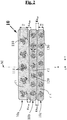
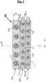
- the figures 2 and 3 show schematically (without respecting a specific scale), in cross section, two examples of multilayer composite laminate (10a, 10b, 10c) used as a belt (10) in the tire (1) according to the invention of the figure 1 , the laminate (10) using reinforcements (110) made of heat-shrinkable textile material respectively in the form of an assembly of three monofilaments ( Fig. 2 ) or a single unitary filament ( Fig. 3 ).
- Ez 1 is the average of the thicknesses (Ez 1 (1) , Ez 1 (2) , Ez 1 (3) , ..., Ez 1 (i) ) of rubber separating a first reinforcement (110) from the second reinforcement ( 120) which is closest to it, these thicknesses each being measured in the radial direction Z, and averaged over a total axial distance between - 5.0 cm and + 5.0 cm from the center of the belt (i.e., for example in total about 100 measurements if there are ten reinforcements (110) per cm in the layer C1).
- Ez 1 is the average of the minimum distances Ez 1 (i) separating "back to back" each first reinforcement (110) from the second reinforcement (120) which is closest to it in the radial direction Z, this average being calculated on all of the first reinforcements (110) present in the central part of the belt, in an axial interval extending between - 5 cm and + 5 cm relative to the median plane M.
- Ez 2 is the average of the thicknesses of rubber (Ez 2 (1) , Ez 2 (2) , Ez 2 (3) , ..., Ez 2 (i) ) separating a second reinforcement (120) from the third reinforcement (130) which is closest to it, measured in the radial direction Z, this average being calculated over a total axial distance between - 5.0 cm and + 5.0 cm from the center of the belt.
- these thicknesses represent the minimum distances which separate “back to back” the second reinforcement (120) from the third reinforcement (130) which is closest to it in the radial direction Z.
- Ez 2 is the average of the minimum distances Ez 2 (i) separating "back to back" each second reinforcement (120) from the third reinforcement (130) which is closest to it in the radial direction Z, this average being calculated on the set of second reinforcements (120) present in the central part of the belt, in an axial interval extending between - 5 cm and + 5 cm relative to the median plane M.
- the tire of the invention preferably checks at least one of the following inequalities (more preferably all three): 0.15 ⁇ Ez 1 / Ez 1 + D 1 + D 2 ⁇ 0.35 0.25 ⁇ Ez 2 / Ez 2 + D 2 + D 3 ⁇ 0.45 0.20 ⁇ Ez 1 + Ez 2 / Ez 1 + Ez 2 + D 1 + D 2 + D 3 ⁇ 0.40 .
- the tire of the invention preferably checks at least one of the following inequalities (more preferably all three): 0.20 ⁇ Ez 1 / Ez 1 + D 1 + D 2 ⁇ 0.30 0.30 ⁇ Ez 2 / Ez 2 + D 2 + D 3 ⁇ 0.40 0.25 ⁇ Ez 1 + Ez 2 / Ez 1 + Ez 2 + D 1 + D 2 + D 3 ⁇ 0.35 .
- the invention offers the possibility of further reducing the thickness of the tire belts and that of the rubber layers constituting a part of their structure, ultimately the weight and the rolling resistance of the tires, thanks to the use in its first layer of monofilaments or assemblies of heat-shrinkable textile monofilaments.
Description
La présente invention est relative aux pneumatiques pour véhicules, et à leur armature de sommet ou ceinture. Elle se rapporte plus particulièrement aux stratifiés composites multicouche utilisés dans la ceinture de tels pneumatiques notamment pour véhicule tourisme ou camionnette.The present invention relates to tires for vehicles, and to their crown or belt reinforcement. It relates more particularly to multilayer composite laminates used in the belt of such tires, in particular for passenger vehicle or van.
Un pneumatique à armature de carcasse radiale pour véhicule tourisme ou camionnette comporte, on le sait, une bande de roulement, deux bourrelets inextensibles, deux flancs souples reliant les bourrelets à la bande de roulement et une armature de sommet rigide ou « ceinture » ("belt") disposée circonférentiellement entre l'armature de carcasse et la bande de roulement.A tire with a radial carcass reinforcement for a passenger vehicle or a van comprises, as is known, a tread, two inextensible beads, two flexible sidewalls connecting the beads to the tread and a rigid crown reinforcement or "belt" ( " belt " ) arranged circumferentially between the carcass reinforcement and the tread.
La ceinture de pneumatique est généralement constituée par au moins deux nappes de caoutchouc dites « nappes de travail », « nappes de triangulation » ou encore « armature de travail », superposées et croisées, renforcées le plus souvent de câbles métalliques disposés sensiblement parallèlement les uns par rapport aux autres et inclinés par rapport au plan circonférentiel médian, ces nappes de travail pouvant être associées ou non à d'autres nappes et/ou tissus de caoutchouc. Ces nappes de travail ont pour fonction première de donner au pneu une rigidité ou poussée de dérive (en anglais, "drift thrust" ou "cornering") élevée, nécessaire de manière connue pour l'obtention d'un bon comportement routier ("handling") sur véhicule automobile.The tire belt is generally made up of at least two plies of rubber known as “working plies”, “triangulation plies” or even “working armature”, superimposed and crossed, most often reinforced with metal cables arranged substantially parallel to one another. with respect to the others and inclined with respect to the median circumferential plane, these working plies may or may not be associated with other plies and / or rubber fabrics. The main function of these working plies is to give the tire a high rigidity or drift thrust (" drift thrust " or " cornering "), necessary in known manner for obtaining good road handling ( "handling " ) on a motor vehicle.
La ceinture ci-dessus, ce qui est particulièrement le cas pour les pneumatiques susceptibles de rouler à haute vitesse de manière soutenue, peut comporter en outre une nappe de caoutchouc additionnelle au-dessus des nappes de travail (côté bande de roulement), dite « nappe de frettage » ou « armature de frettage », qui est renforcée généralement par des fils de renforcement dits « circonférentiels », c'est-à-dire que ces fils de renforcement sont disposés pratiquement parallèles les uns aux autres et s'étendent sensiblement circonférentiellement autour de l'enveloppe pneumatique de manière à former un angle préférentiellement compris dans un domaine de -5° à +5° avec le plan circonférentiel médian. Ces fils de renforcement circonférentiels ont pour fonction première, on le rappelle, de résister à la centrifugation du sommet à haute vitesse.The above belt, which is particularly the case for tires capable of rolling at high speed in a sustained manner, may further comprise an additional rubber ply above the working plies (tread side), called " hooping ply "or" hooping reinforcement ", which is generally reinforced by so-called" circumferential "reinforcing threads, that is to say that these reinforcing threads are arranged practically parallel to one another and extend substantially circumferentially around the pneumatic envelope so as to form an angle preferably comprised in a range of -5 ° to + 5 ° with the median circumferential plane. These circumferential reinforcement wires have the primary function, it will be recalled, of resisting centrifugation of the crown at high speed.
De telles structures de ceintures, consistant finalement en un stratifié composite multicouche comportant au moins une nappe de frettage, le plus souvent textile, et deux nappes de travail généralement métalliques, sont bien connues de l'homme du métier et ne nécessitent pas d'être décrites ici plus en détail.Such belt structures, ultimately consisting of a multilayer composite laminate comprising at least one hooping ply, most often textile, and two generally metallic working plies, are well known to those skilled in the art and do not need to be described here in more detail.
L'état de la technique général décrivant de telles structures de ceintures est illustré en particulier par les documents brevet
La disponibilité en aciers de plus en plus résistants et endurants fait que les manufacturiers de pneumatiques s'orientent aujourd'hui, autant que possible, vers l'emploi dans les ceintures de pneumatiques de câbles à structure très simple, notamment à seulement deux fils, voire même de filaments unitaires, afin d'une part de simplifier la fabrication et diminuer les coûts, d'autre part de diminuer l'épaisseur des nappes de renforcement et ainsi l'hystérèse des pneumatiques, en fin de compte réduire la consommation d'énergie des véhicules équipés de tels pneumatiques.The availability of increasingly resistant and enduring steels means that tire manufacturers are nowadays orienting themselves, as much as possible, towards the use in tire belts of cables of very simple structure, in particular with only two wires, or even single filaments, on the one hand to simplify manufacture and reduce costs, on the other hand to reduce the thickness of the reinforcing plies and thus the hysteresis of tires, ultimately reducing the consumption of energy of vehicles fitted with such tires.
Les efforts visant à réduire la masse des pneumatiques, en particulier par une réduction d'épaisseur de leur ceinture et des couches de caoutchouc la constituant, se heurtent toutefois, bien naturellement, à des limites physiques qui peuvent donner lieu à un certain nombre de difficultés. Il peut notamment se produire que la fonction de frettage apportée par l'armature de frettage et celle de rigidification apportée par l'armature de travail ne soient plus suffisamment différenciées l'une de l'autre et puissent se perturber mutuellement. Ceci est préjudiciable au bon fonctionnement du sommet du pneumatique, à la performance et l'endurance globale du pneumatique.Efforts to reduce the mass of tires, in particular by reducing the thickness of their belts and the layers of rubber making them up, however, naturally come up against physical limits which can give rise to a certain number of difficulties. . It may in particular occur that the hooping function provided by the hooping frame and that of stiffening provided by the working frame are no longer sufficiently differentiated from each other and can disturb each other. This is detrimental to the proper functioning of the top of the tire, to the overall performance and endurance of the tire.
C'est ainsi que les demandes de brevet
Ces demandes divulguent un pneumatique radial, définissant trois directions principales, circonférentielle, axiale et radiale, comportant un sommet surmonté d'une bande de roulement, deux flancs, deux bourrelets, chaque flanc reliant chaque bourrelet au sommet, une armature de carcasse ancrée dans chacun des bourrelets et s'étendant dans les flancs et dans le sommet, une armature de sommet ou ceinture s'étendant dans le sommet selon la direction circonférentielle et située radialement entre l'armature de carcasse et la bande de roulement, ladite ceinture comportant un stratifié composite multicouche comportant au moins trois couches superposées de renforts, lesdits renforts étant dans chaque couche unidirectionnels et noyés dans une épaisseur de caoutchouc, avec notamment :
- ∘ côté bande de roulement, une première couche de caoutchouc comportant une première rangée de renforts, orientés selon un angle alpha de -5 à +5 degrés par rapport à la direction circonférentielle, ces renforts dits premiers renforts étant en matériau textile thermorétractile ;
- ∘ au contact de la première couche et disposée sous cette dernière, une deuxième couche de caoutchouc comportant une deuxième rangée de renforts, orientés selon un angle beta donné, positif ou négatif, compris entre 10 et 30 degrés par rapport à la direction circonférentielle, ces renforts dits deuxièmes renforts étant des renforts métalliques ;
- ∘ au contact de la deuxième couche et disposée sous cette dernière, une troisième couche de caoutchouc comportant une troisième rangée de renforts, orientés selon un angle gamma opposé à l'angle beta, lui-même compris entre 10 et 30 degrés par rapport à la direction circonférentielle, ces renforts dits troisièmes renforts étant des renforts métalliques.
- ∘ tread side, a first layer of rubber comprising a first row of reinforcements, oriented at an angle alpha of -5 to +5 degrees relative to the circumferential direction, these reinforcements called first reinforcements being made of heat-shrinkable textile material;
- ∘ in contact with the first layer and placed under the latter, a second layer of rubber comprising a second row of reinforcements, oriented at a given beta angle, positive or negative, between 10 and 30 degrees relative to the circumferential direction, these reinforcements called second reinforcements being metallic reinforcements;
- ∘ in contact with the second layer and placed under the latter, a third layer of rubber comprising a third row of reinforcements, oriented at a gamma angle opposite to the beta angle, itself between 10 and 30 degrees relative to the circumferential direction, these reinforcements called third reinforcements being metallic reinforcements.
Les premiers renforts, préférentiellement en polyamide ou en polyester, sont constitués de fibres multifilamentaires comportant un très grand nombre (typiquement plusieurs centaines) de filaments élémentaires de très petit diamètre, qui sont retordues ensemble sous forme de cordes textiles conventionnelles. Les deuxièmes et troisièmes renforts consistent quant à eux en des monofilaments unitaires en acier, en particulier en acier au carbone à très haute résistance.The first reinforcements, preferably made of polyamide or polyester, consist of multifilament fibers comprising a very large number (typically several hundred) of elementary filaments of very small diameter, which are twisted together in the form of conventional textile cords. The second and third reinforcements, for their part, consist of unitary steel monofilaments, in particular very high strength carbon steel.
Les demandes de brevet ci-dessus ont démontré qu'il était possible, grâce à la construction spécifique de leur stratifié composite multicouche, notamment à l'utilisation de renforts circonférentiels textiles dont la thermorétractabilité est contrôlée et de renforts métalliques sous forme de monofils unitaires de faible diamètre, de réduire de manière notable l'épaisseur globale des ceintures de pneumatiques, et ceci sans nuire à la bonne mise en œuvre et à la différentiation des fonctions d'une part de frettage apportées par les renforts circonférentiels de la première couche, d'autre part de rigidification apportées par les renforts métalliques des deux autres couches.The above patent applications have demonstrated that it is possible, thanks to the specific construction of their multilayer composite laminate, in particular to the use of textile circumferential reinforcements whose heat shrinkage is controlled and of metallic reinforcements in the form of unitary monofilaments. small diameter, to significantly reduce the overall thickness of the tire belts, and this without adversely affecting the correct implementation and the differentiation of the functions on the one hand of hooping provided by the circumferential reinforcements of the first layer, d 'other part of stiffening provided by the metal reinforcements of the other two layers.
Ainsi, peuvent être diminués le poids des pneumatiques et leur résistance au roulement, à coût réduit grâce à l'utilisation de monofilaments en acier ne nécessitant aucune opération d'assemblage préalable, et ceci sans pénaliser la rigidité de dérive ni l'endurance globale en roulage.Thus, the weight of the tires and their rolling resistance can be reduced, at reduced cost thanks to the use of steel monofilaments which do not require any prior assembly operation, and this without penalizing the stiffness of drift or the overall endurance in rolling.
L'objectif de manufacturiers de pneumatiques, partant des stratifiés multicouche décrits dans les deux demandes ci-dessus, de réduire encore les épaisseurs des (première, deuxième et troisième) couches de caoutchouc se heurte maintenant au risque d'engendrer selon la direction radiale (Z), ici ou là dans le sommet du pneumatique, des contacts directs entre les renforts de ces différentes couches, ce qui serait préjudiciable au bon fonctionnement et à l'endurance du stratifié.The objective of tire manufacturers, starting from the multilayer laminates described in the two applications above, to further reduce the thicknesses of the (first, second and third) layers of rubber now runs up against the risk of generating in the radial direction ( Z), here or there in the top of the tire, direct contacts between the reinforcements of these different layers, which would be detrimental to the proper functioning and endurance of the laminate.
En particulier, un contact direct entre les renforts textiles circonférentiels, dont on sait qu'ils contiennent naturellement et sont susceptibles de transporter une certaine quantité d'eau, variable selon la nature du matériau textile thermorétractile, et les monofilaments en acier, pourrait engendrer à terme une corrosion de surface de ces derniers, donc une perte de résistance, sans parler d'un risque de dégradation de l'adhésion avec le caoutchouc environnant, in fine un risque de diminution de l'endurance globale de l'armature de travail après un roulage prolongé des pneumatiques.In particular, direct contact between the circumferential textile reinforcements, which are known to contain naturally and are capable of transporting a certain amount of water, which varies according to the nature of the heat-shrinkable textile material, and the steel monofilaments, could lead to term surface corrosion of the latter, therefore a loss of strength, not to mention a risk of degradation of the adhesion with the surrounding rubber, ultimately a risk of reduction in the overall endurance of the working reinforcement after prolonged rolling of the tires.
Poursuivant leurs recherches, les Demanderesses ont mis au point un stratifié composite multicouche amélioré, d'architecture nouvelle, qui répond au problème ci-dessus et qui peut donc constituer une alternative avantageuse aux stratifiés décrits dans les deux demandes précitées, lorsqu'on souhaite réduire encore les épaisseurs des couches de caoutchouc et par voie de conséquence la résistance au roulement des pneumatiques.Continuing their research, the Applicants have developed an improved multilayer composite laminate, of new architecture, which addresses the above problem and which can therefore constitute an advantageous alternative to the laminates described in the two aforementioned applications, when it is desired to reduce the thicknesses of the rubber layers and consequently the rolling resistance of the tires.
Ainsi, selon un premier objet, la présente invention concerne (selon les références données aux
- ∘ côté bande de roulement, une première couche (10a) de caoutchouc (C1) comportant une première rangée de renforts (110), orientés selon un angle alpha de -5 à +5 degrés par rapport à la direction circonférentielle (X), ces renforts (110) dits premiers renforts étant en matériau textile thermorétractile ;
- ∘ au contact de la première couche (10b) et disposée sous cette dernière, une deuxième couche (10b) de caoutchouc (C2) comportant une deuxième rangée de renforts (120), orientés selon un angle beta donné, positif ou négatif, compris entre 10 et 30 degrés par rapport à la direction circonférentielle (X), ces renforts (120) dits deuxièmes renforts étant des renforts métalliques ;
- ∘ au contact de la deuxième couche (10b) et disposée sous cette dernière, une troisième couche (10c) de caoutchouc (C3) comportant une troisième rangée de renforts (130), orientés selon un angle gamma opposé à l'angle beta, lui-même compris entre 10 et 30 degrés par rapport à la direction circonférentielle (X), ces renforts (130) dits troisièmes renforts étant des renforts métalliques,
- ∘ les premiers renforts (110) en matériau textile thermorétractile sont des mono filaments de diamètre ou épaisseur ϕ supérieur(e) à 0,10 mm, ou des assemblages de tels mono filaments ;
- ∘ le diamètre d'encombrement noté D1 des premiers renforts (110) est compris entre 0,20 mm et 1,20 mm ;
- ∘ les deuxièmes (120) et troisièmes (130) renforts sont des mono filaments en acier de diamètre ou épaisseur, respectivement D2 et D3, compris(e) entre 0,20 mm et 0,50 mm ;
- les caractéristiques suivantes, mesurées dans la partie centrale de la ceinture du pneumatique à l'état vulcanisé, de part et d'autre du plan médian (M) sur une largeur axiale totale de 10 cm, sont vérifiées :
- l'épaisseur moyenne Ez1 de caoutchouc séparant un premier renfort (110) du deuxième renfort (120) qui lui est le plus proche, mesurée dans la direction radiale (Z), est inférieure ou égale à 0,35 mm ;
- l'épaisseur moyenne Ez2 de caoutchouc séparant un deuxième renfort (120) du troisième renfort (130) qui lui est le plus proche, mesurée dans la direction radiale (Z), est inférieure ou égale à 0,35 mm.
- les caractéristiques suivantes, mesurées dans la partie centrale de la ceinture du pneumatique à l'état vulcanisé, de part et d'autre du plan médian (M) sur une largeur axiale totale de 10 cm, sont vérifiées :
- ∘ tread side, a first layer (10a) of rubber (C1) comprising a first row of reinforcements (110), oriented at an alpha angle of -5 to +5 degrees relative to the circumferential direction (X), these reinforcements (110) said first reinforcements being made of heat-shrinkable textile material;
- ∘ in contact with the first layer (10b) and disposed under the latter, a second layer (10b) of rubber (C2) comprising a second row of reinforcements (120), oriented at a given beta angle, positive or negative, between 10 and 30 degrees relative to the circumferential direction (X), these reinforcements (120) said second reinforcements being metallic reinforcements;
- ∘ in contact with the second layer (10b) and arranged under the latter, a third layer (10c) of rubber (C3) comprising a third row of reinforcements (130), oriented at a gamma angle opposite to the beta angle, even between 10 and 30 degrees relative to the circumferential direction (X), these reinforcements (130) called third reinforcements being metallic reinforcements,
- ∘ the first reinforcements (110) of heat-shrinkable textile material are monofilaments of diameter or thickness ϕ greater than 0.10 mm, or assemblies of such monofilaments;
- ∘ the overall diameter noted D1 of the first reinforcements (110) is between 0.20 mm and 1.20 mm;
- ∘ the second (120) and third (130) reinforcements are single steel filaments of diameter or thickness, respectively D2 and D3, between (0.20 mm and 0.50 mm);
- the following characteristics, measured in the central part of the tire belt in the vulcanized state, on either side of the median plane (M) over a total axial width of 10 cm, are verified:
- the average thickness Ez 1 of rubber separating a first reinforcement (110) from the second reinforcement (120) which is closest to it, measured in the radial direction (Z), is less than or equal to 0.35 mm;
- the average thickness Ez 2 of rubber separating a second reinforcement (120) from the third reinforcement (130) which is closest to it, measured in the radial direction (Z), is less than or equal to 0.35 mm.
- the following characteristics, measured in the central part of the tire belt in the vulcanized state, on either side of the median plane (M) over a total axial width of 10 cm, are verified:
Les risques de corrosion ou de perte d'adhésion évoqués ci-dessus sont réduits de manière notable, dans le stratifié, grâce à l'emploi de renforts textiles (110) sous forme de mono filaments de gros diamètre ou d'assemblages de tels monofilaments, en lieu et place des cordes textiles conventionnelles à base de fibres multifilamentaires telles que décrites dans les demandes
Le stratifié composite multicouche selon l'invention est utilisable comme élément de renforcement de ceinture de tout type de pneumatique, particulièrement pour véhicule tourisme incluant notamment les véhicules 4x4 et "SUV" (Sport Utility Vehicles) ou pour véhicule camionnette.The multilayer composite laminate according to the invention can be used as a belt reinforcement element for any type of tire, particularly for passenger vehicles including in particular 4x4 and "SUV" vehicles ( Sport Utility Vehicles ) or for van vehicles.
L'invention ainsi que ses avantages seront aisément compris à la lumière de la description détaillée et des exemples de réalisation qui suivent, ainsi que des
- en coupe radiale (c'est-à-dire selon un plan contenant l'axe de rotation du pneumatique), un exemple de pneumatique (1) conforme à l'invention, incorporant dans sa ceinture (10) un stratifié composite multicouche conformément à l'invention (
Fig. 1 ) ; - en coupe transversale, deux exemples de stratifié composite multicouche (10a, 10b, 10c) utilisé dans le pneumatique (1) conforme à l'invention, utilisant les renforts (110) en matériau textile thermorétractile respectivement sous la forme d'un assemblage de mono filaments (
Fig. 2 ) ou d'un mono filament unitaire (Fig. 3 ) ; - en coupe transversale, différents exemples possibles d'assemblages de mono filaments (111) en matériau textile thermorétractile, utilisables comme renforts (110) dans la première couche (10a) du stratifié composite multicouche selon l'invention (
Fig. 4 ).
- in radial section (that is to say along a plane containing the axis of rotation of the tire), an example of a tire (1) according to the invention, incorporating in its belt (10) a multilayer composite laminate in accordance with the invention (
Fig. 1 ); - in cross section, two examples of multilayer composite laminate (10a, 10b, 10c) used in the tire (1) according to the invention, using the reinforcements (110) made of heat-shrinkable textile material respectively in the form of a mono assembly filaments (
Fig. 2 ) or a single unit filament (Fig. 3 ); - in cross section, different possible examples of assemblies of monofilaments (111) of heat-shrinkable textile material, usable as reinforcements (110) in the first layer (10a) of the multilayer composite laminate according to the invention (
Fig. 4 ).
Dans la présente demande, on entend par :
- "caoutchouc" ou "élastomère" (les deux termes étant considérés comme synonymes) : tout type d'élastomère, qu'il soit du type diénique ou du type non diénique par exemple thermoplastique ;
- "composition de caoutchouc" ou "composition caoutchouteuse" : une composition qui comporte au moins un caoutchouc et une charge ;
- "couche" : une feuille, bande ou tout autre élément d'épaisseur relativement faible par rapport à ses autres dimensions, de préférence dont le rapport de l'épaisseur sur la plus grande des autres dimensions est inférieur à 0,5, plus préférentiellement inférieur à 0,1 ;
- "direction axiale" : une direction sensiblement parallèle à l'axe de rotation du pneumatique ;
- "direction circonférentielle" : une direction qui est sensiblement perpendiculaire à la fois à la direction axiale et à un rayon du pneumatique (en d'autres termes, tangente à un cercle dont le centre est sur l'axe de rotation du pneumatique) ;
- "direction radiale" : une direction selon un rayon du pneumatique, c'est-à-dire une direction quelconque passant par l'axe de rotation du pneumatique et sensiblement perpendiculairement à cette direction, c'est-à-dire faisant avec une perpendiculaire à cette direction un angle ne s'écartant pas de plus de 5 degrés ;
- "monofilament" ou indistinctement "monofil", de manière générale, tout filament unitaire, quelle que soit la forme de sa section droite, dont le diamètre (cas d'une section droite circulaire) ou l'épaisseur (cas d'une section droite non circulaire) sont supérieurs à 100 µm. Cette définition couvre aussi bien des monofils de forme essentiellement cylindrique (à section droite circulaire) que des mono filaments de forme différente, par exemple des monofilaments oblongs (de forme aplatie), ou de section droite rectangulaire ou carrée ;
- "orienté selon un axe ou une direction" en parlant d'un élément quelconque tel qu'un renfort, un élément qui est orienté sensiblement parallèlement à cet axe ou cette direction, c'est-à-dire faisant avec cet axe ou cette direction un angle ne s'écartant pas de plus de 5 degrés (donc nul ou au plus égal à 5 degrés) ;
- "orienté perpendiculairement à un axe ou une direction" : en parlant d'un élément quelconque tel qu'un renfort, un élément qui est orienté sensiblement perpendiculairement à cet axe ou cette direction, c'est-à-dire faisant avec une perpendiculaire à cet axe ou cette direction un angle ne s'écartant pas de plus de 5 degrés ;
- "plan circonférentiel médian" (noté M) : le plan perpendiculaire à l'axe Y de rotation du pneumatique qui est situé à mi-distance des deux bourrelets et passe par le milieu de l'armature de sommet ou ceinture ;
- "renfort" ou "fil de renforcement" : tout brin long et fin c'est-à-dire filiforme, longiligne, de grande longueur relativement à sa section transversale, notamment tout filament unitaire, toute fibre multifilamentaire ou tout assemblage de tels filaments ou fibres tels qu'un retors ou un câble, ce brin ou fil pouvant être rectiligne comme non rectiligne, par exemple torsadé, ou ondulé, un tel brin ou fil étant susceptible de renforcer une matrice de caoutchouc (c'est-à-dire augmenter les propriétés en traction de la matrice) ;
- "renforts unidirectionnels" : des renforts essentiellement parallèles entre eux, c'est-à-dire orientés selon un même axe ;
- "stratifié" ou "stratifié multicouche" : au sens de la classification internationale des brevets, tout produit comportant au moins deux couches, de forme plane ou non plane, qui sont au contact l'une de l'autre, ces dernières pouvant être ou non liées, connectées entre elles ; l'expression "lié" ou "connecté" doit être interprétée de façon extensive de manière à inclure tous les moyens de liaison ou d'assemblage, en particulier par collage.
- "rubber" or "elastomer" (the two terms being considered as synonyms): any type of elastomer, whether it is of the diene type or of the non-diene type, for example thermoplastic;
- "rubber composition" or "rubber composition": a composition which comprises at least one rubber and one filler;
- "layer": a sheet, strip or any other element of relatively small thickness compared to its other dimensions, preferably whose ratio of the thickness to the largest of the other dimensions is less than 0.5, more preferably less 0.1;
- "axial direction": a direction substantially parallel to the axis of rotation of the tire;
- "circumferential direction": a direction which is substantially perpendicular both to the axial direction and to a radius of the tire (in other words, tangent to a circle whose center is on the axis of rotation of the tire);
- "radial direction": a direction along a radius of the tire, that is to say any direction passing through the axis of rotation of the tire and substantially perpendicular to this direction, that is to say making with an perpendicular to this direction an angle not deviating by more than 5 degrees;
- "monofilament" or indiscriminately "monofilament", in general, any unitary filament, whatever the shape of its cross section, whose diameter (case of a circular cross section) or thickness (case of a straight section not circular) are greater than 100 µm. This definition covers both monofilaments of essentially cylindrical shape (with circular cross section) and monofilaments of different shape, for example oblong monofilaments (of flattened shape), or of rectangular or square cross section;
- "oriented along an axis or a direction" by speaking of any element such as a reinforcement, an element which is oriented substantially parallel to this axis or this direction, that is to say making with this axis or this direction an angle not deviating by more than 5 degrees (therefore zero or at most equal to 5 degrees);
- "oriented perpendicular to an axis or a direction": speaking of any element such as a reinforcement, an element which is oriented substantially perpendicular to this axis or this direction, that is to say making with a perpendicular to this axis or this direction an angle not deviating by more than 5 degrees;
- "median circumferential plane" (denoted M): the plane perpendicular to the axis Y of rotation of the tire which is located midway between the two beads and passes through the middle of the crown or belt reinforcement;
- "reinforcement" or "reinforcing wire": any long and fine strand, that is to say filiform, slender, of great length relative to its cross section, in particular any unitary filament, any multifilament fiber or any assembly of such filaments or fibers such as a plied or a cable, this strand or wire being able to be rectilinear as non-rectilinear, for example twisted, or corrugated, such a strand or thread being capable of reinforcing a rubber matrix (i.e. increasing the tensile properties of the matrix);
- "unidirectional reinforcements": reinforcements essentially parallel to one another, that is to say oriented along the same axis;
- "laminate" or "multilayer laminate": within the meaning of the international patent classification, any product comprising at least two layers, of planar or non-planar shape, which are in contact with one another, the latter possibly being or not linked, connected to each other; the expression "linked" or "connected" must be interpreted in a comprehensive manner so as to include all the means of connection or assembly, in particular by bonding.
D'autre part, sauf indication expresse différente, tous les pourcentages (%) indiqués sont des % en masse.On the other hand, unless otherwise expressly indicated, all the percentages (%) indicated are% by mass.
L'expression « x et/ou y » signifie « x » ou « y » ou les deux (c'est-à-dire « x et y »). Tout intervalle de valeurs désigné par l'expression « entre a et b » représente le domaine de valeurs allant de plus de « a » à moins de « b » (c'est-à-dire bornes « a » et « b » exclues) tandis que tout intervalle de valeurs désigné par l'expression « de a à b » signifie le domaine de valeurs allant de « a » jusqu'à « b » (c'est-à-dire incluant les bornes strictes « a » et « b »).The expression "x and / or y" means "x" or "y" or both (ie "x and y"). Any range of values designated by the expression "between a and b" represents the range of values going from more than "a" to less than "b" (ie limits "a" and "b" excluded ) while any range of values designated by the expression "from a to b" means the range of values going from "a" to "b" (that is to say including the strict limits "a" and "b" ).
A titre d'exemple, la
Ce pneumatique (1) conforme à l'invention, définissant trois directions perpendiculaires, circonférentielle (X), axiale (Y) et radiale (Z), comporte un sommet (2) surmonté d'une bande de roulement (3), deux flancs (4), deux bourrelets (5), chaque flanc (4) reliant chaque bourrelet (5) au sommet (2), une armature de carcasse (7) ancrée dans chacun des bourrelets (5) et s'étendant dans les flancs (4) jusqu'au sommet (2), une armature de sommet ou ceinture (10) s'étendant dans le sommet (2) selon la direction circonférentielle (X) et situé radialement entre l'armature de carcasse (7) et la bande de roulement (3). L'armature de carcasse (7) est de manière connue constituée d'au moins une nappe de caoutchouc renforcée par des câblés textiles dits "radiaux", disposés pratiquement parallèles les uns aux autres et s'étendent d'un bourrelet à l'autre de manière à former un angle généralement compris entre 80° et 90° avec le plan circonférentiel médian M ; elle est ici, à titre d'exemple, enroulée autour de deux tringles (6) dans chaque bourrelet (5), le retournement (8) de cette armature (7) étant par exemple disposé vers l'extérieur du pneumatique (1) qui est ici représenté monté sur sa jante (9).This tire (1) according to the invention, defining three perpendicular, circumferential (X), axial (Y) and radial (Z) directions, has a crown (2) surmounted by a tread (3), two sidewalls (4), two beads (5), each side (4) connecting each bead (5) to the top (2), a carcass reinforcement (7) anchored in each of the beads (5) and extending in the sides ( 4) to the top (2), a top reinforcement or belt (10) extending in the top (2) in the circumferential direction (X) and located radially between the carcass reinforcement (7) and the strip bearing (3). The carcass reinforcement (7) is in known manner made up of at least one rubber ply reinforced by so-called "radial" textile cords, arranged practically parallel to one another and extending from one bead to the other so as to form an angle generally between 80 ° and 90 ° with the median circumferential plane M; it is here, for example, wound around two rods (6) in each bead (5), the reversal (8) of this frame (7) being for example disposed towards the outside of the tire (1) which is shown here mounted on its rim (9).
Selon la présente invention, conformément aux représentations des
- ∘ côté bande de roulement, une première couche (10a) de caoutchouc (C1) comportant une première rangée de renforts (110), orientés selon un angle alpha de -5 à +5 degrés par rapport à la direction circonférentielle (X), ces renforts (110) dits premiers renforts étant en matériau textile thermorétractile ;
- ∘ au contact de la première couche (10b) et disposée sous cette dernière, une deuxième couche (10b) de caoutchouc (C2) comportant une deuxième rangée de renforts (120), orientés selon un angle beta donné, positif ou négatif, compris entre 10 et 30 degrés par rapport à la direction circonférentielle (X), ces renforts (120) dits deuxièmes renforts étant des renforts métalliques ;
- ∘ au contact de la deuxième couche (10b) et disposée sous cette dernière, une troisième couche (10c) de caoutchouc (C3) comportant une troisième rangée de renforts (130), orientés selon un angle gamma opposé à l'angle beta, lui-même compris entre 10 et 30 degrés par rapport à la direction circonférentielle (X), identique à ou différent de l'angle beta, ces renforts (130) dits troisièmes renforts étant des renforts métalliques.
- ∘ tread side, a first layer (10a) of rubber (C1) comprising a first row of reinforcements (110), oriented at an angle alpha of -5 to +5 degrees relative to the circumferential direction (X), these reinforcements (110) said first reinforcements being of heat-shrinkable textile material;
- ∘ in contact with the first layer (10b) and disposed under the latter, a second layer (10b) of rubber (C2) comprising a second row of reinforcements (120), oriented at a given beta angle, positive or negative, between 10 and 30 degrees relative to the circumferential direction (X), these reinforcements (120) called second reinforcements being metallic reinforcements;
- ∘ in contact with the second layer (10b) and arranged under the latter, a third layer (10c) of rubber (C3) comprising a third row of reinforcements (130), oriented at a gamma angle opposite to the beta angle, even between 10 and 30 degrees with respect to the circumferential direction (X), identical to or different from the beta angle, these reinforcements (130) called third reinforcements being metallic reinforcements.
Selon l'invention, les angles β et γ de sens opposés, tous deux compris entre 10° et 30°, peuvent être identiques ou différents, c'est-à-dire que les deuxièmes (120) et troisièmes (130) renforts peuvent être disposés symétriquement ou pas, de part et d'autre du plan circonférentiel médian (M) précédemment défini.According to the invention, the angles β and γ of opposite directions, both between 10 ° and 30 °, can be identical or different, that is to say that the second (120) and third (130) reinforcements can be arranged symmetrically or not, on either side of the previously defined median circumferential plane (M).
Dans ce pneumatique schématisé à la
Selon une première caractéristique essentielle de l'invention, les premiers renforts (110) en matériau textile thermorétractile sont des monofils ou des assemblages de monofils, de tels monofils pris individuellement ayant un diamètre (ou, par définition, une épaisseur si le monofilament n'a pas une section droite sensiblement circulaire) noté ϕ qui est supérieur à 0,10 mm, de préférence compris entre 0,15 et 0,80 mm, en particulier entre 0,20 et 0,60 mm.According to a first essential characteristic of the invention, the first reinforcements (110) of heat-shrinkable textile material are monofilaments or assemblies of monofilaments, such monofilaments taken individually having a diameter (or, by definition, a thickness if the monofilament does not not a substantially circular cross section) noted ϕ which is greater than 0.10 mm, preferably between 0.15 and 0.80 mm, in particular between 0.20 and 0.60 mm.
Le diamètre d'encombrement (moyen) D1 de ces premiers renforts textiles (110) est quant à lui compris entre 0,20 mm et 1,20 mm, de préférence entre 0,30 et 1,00 mm, en particulier entre 0,40 et 0,80 mm ; en d'autres termes, dans le cas particulier où le renfort (110) consiste en un monofilament textile unitaire de section droite circulaire, ce dernier a un diamètre ϕ qui est nécessairement supérieur à 0,20 mm. On entend de manière usuelle par diamètre d'encombrement le diamètre du cylindre de révolution imaginaire qui entoure de tels premiers renforts textiles (110) dans le cas général où ces derniers ne sont pas à section droite circulaire.The overall diameter D1 of these first textile reinforcements (110) is between 0.20 mm and 1.20 mm, preferably between 0.30 and 1.00 mm, in particular between 0, 40 and 0.80 mm; in other words, in the particular case where the reinforcement (110) consists of a unitary textile monofilament of circular cross section, the latter has a diameter ϕ which is necessarily greater than 0.20 mm. The usual denomination diameter is understood to mean the diameter of the imaginary cylinder of revolution which surrounds such first textile reinforcements (110) in the general case where the latter are not of circular cross section.
Tout matériau textile thermorétractile convient, en particulier et préférentiellement un matériau textile vérifiant les caractéristiques de contraction CT énoncées ci-après convient.Any heat-shrinkable textile material is suitable, in particular and preferably a textile material verifying the CT contraction characteristics set out below is suitable.
De préférence, ce matériau textile thermorétractile est choisi dans le groupe constitué par les polyamides, les polyesters et les polycétones. Parmi les polyamides, on peut citer notamment les polyamides 4-6, 6, 6-6, 11 ou 12. Parmi les polyesters, on peut citer par exemple les PET (polyéthylène téréphthalate), PEN (polyéthylène naphthalate), PBT (polybutylène téréphthalate), PBN (polybutylène naphthalate), PPT (polypropylène téréphthalate), PPN (polypropylène naphthalate). Sont également utilisables, en particulier et préférentiellement dans la mesure où ils vérifient la caractéristique CT préconisée ci-dessus, des renforts hybrides constitués de deux (au moins deux) matériaux différents tels que par exemple des assemblages de monofilaments aramide/nylon, aramide/polyester, aramide/polycétone.Preferably, this heat-shrinkable textile material is chosen from the group consisting of polyamides, polyesters and polyketones. Among the polyamides, mention may in particular be made of polyamides 4-6, 6, 6-6, 11 or 12. Among the polyesters, mention may, for example, be made of PET (polyethylene terephthalate), PEN (polyethylene naphthalate), PBT (polybutylene terephthalate) ), PBN (polybutylene naphthalate), PPT (polypropylene terephthalate), PPN (polypropylene naphthalate). Are also usable, in particular and preferably insofar as they verify the characteristic CT recommended above, hybrid reinforcements made up of two (at least two) different materials such as for example assemblies of aramid / nylon, aramid / polyester monofilaments , aramid / polyketone.
Plus préférentiellement, le matériau textile thermorétractile constitutif des premiers renforts (110) est un polyamide (nylon) ou un polyester.More preferably, the heat-shrinkable textile material constituting the first reinforcements (110) is a polyamide (nylon) or a polyester.
La densité d1 des premiers renforts (110) dans la première couche de caoutchouc (C1), mesurée dans la direction axiale (Y), est de préférence comprise entre 70 et 130 fils/dm, plus préférentiellement comprise entre 80 et 120 fils/dm, en particulier entre 90 et 110 fils/dm.The density d 1 of the first reinforcements (110) in the first rubber layer (C1), measured in the axial direction (Y), is preferably between 70 and 130 threads / dm, more preferably between 80 and 120 threads / dm, in particular between 90 and 110 threads / dm.
Leur contraction thermique (notée CT), après 2 min à 185°C, est de préférence inférieure à 7,5%, plus préférentiellement inférieure à 7,0%, en particulier inférieure à 6,0%, valeurs qui se sont révélées préférables pour la stabilité de fabrication et de dimensionnement des enveloppes de pneumatiques, en particulier lors des phases de cuisson et refroidissement des ces dernières.Their thermal contraction (denoted CT), after 2 min at 185 ° C., is preferably less than 7.5%, more preferably less than 7.0%, in particular less than 6.0%, values which have been found to be preferable. for the manufacturing and dimensioning stability of tire casings, in particular during the curing and cooling phases thereof.
Il s'agit de la contraction relative de ces premiers renforts (110) dans les conditions énoncées ci-après du test. La grandeur CT est mesurée, sauf précisions différentes, selon la norme ASTM D1204-08, par exemple sur un appareil du type « TESTRITE », sous une prétension dite standard de 0,5 cN/tex (donc ramenée au titre ou densité linéique de l'échantillon testé). A longueur constante, on mesure également le maximum de la force de contraction (notée FC) à l'aide du test ci-dessus, cette fois à une température de 180°C et sous 3% d'élongation. Cette force de contraction FC est préférentiellement supérieure à 20 N (Newton). Une force de contraction élevée s'est révélée particulièrement favorable à la capacité de frettage des premiers renforts (110) en matériau textile thermorétractile, vis-à-vis de l'armature de sommet du pneumatique lorsque ce dernier s'échauffe sous une haute vitesse de roulage.This is the relative contraction of these first reinforcements (110) under the conditions set out below of the test. The magnitude CT is measured, unless otherwise specified, according to standard ASTM D1204-08, for example on a device of the “TESTRITE” type, under a pretension known as standard of 0.5 cN / tex (therefore reduced to the titer or linear density of the tested sample). At constant length, the maximum of the contraction force (denoted F C ) is also measured using the above test, this time at a temperature of 180 ° C. and under 3% elongation. This contraction force F C is preferably greater than 20 N (Newton). A high contraction force has been found to be particularly favorable to the hooping capacity of the first reinforcements (110) made of heat-shrinkable textile material, vis-à-vis the crown reinforcement of the tire when the latter heats up at high speed. of rolling.
Les grandeurs CT et FC ci-dessus peuvent être indistinctement mesurées sur les renforts textiles initiaux encollés avant leur incorporation dans le stratifié puis dans le pneu, ou bien mesurée sur ces renforts une fois extraits de la zone centrale du pneumatique vulcanisé et de préférence « dégommés » (c'est-à-dire débarrassés du caoutchouc qui les enrobe dans la couche C1).The sizes CT and F C above can be measured without distinction on the initial textile reinforcements glued before their incorporation in the laminate and then in the tire, or else measured on these reinforcements once extracted from the central zone of the vulcanized tire and preferably " degummed ”(that is to say, freed from the rubber which coats them in layer C1).
La
De tels assemblages et leurs procédés de fabrication sont bien connus de l'homme du métier ; ils ont été décrits dans de nombreux documents brevet, à titre d'exemples
Les monofils ou assemblages de monofils textiles thermorétractiles présentent l'avantage, comparativement à des cordes textiles formées de fibres multifilamentaires conventionnelles, de mieux protéger contre l'humidité le reste du stratifié composite multicouche, ainsi de limiter les risques de pénaliser l'adhésion entre les divers renforts du stratifié et leur matrice de caoutchouc environnante, sans compter les risques de corrosion de surface des mono filaments en acier.Heat-shrinkable textile monofilaments or assemblies of monofilaments have the advantage, compared to textile cords formed of conventional multifilament fibers, of better protecting against moisture the rest of the multilayer composite laminate, thus limiting the risks of penalizing the adhesion between the various reinforcements of the laminate and their surrounding rubber matrix, without taking into account the risks of surface corrosion of the steel mono filaments.
Si des assemblages de monofils textiles sont utilisés, ils comportent de préférence 2 à 10, plus préférentiellement de 3 à 7 monofils en matériau textile thermorétractile tel que par exemple polyamide, polyester ou polycétone. Pour la fabrication de ces assemblages, les monofils sont câblés, retordus ensemble selon des techniques bien connues, avec une torsion comprise de préférence entre 30 et 200 tr/m (tours par mètre), plus préférentiellement entre 30 et 100 tr/m, ces monofils étant de manière connue dépourvus, ou quasiment dépourvus, de torsion sur eux-mêmes.If assemblies of textile monofilaments are used, they preferably comprise 2 to 10, more preferably from 3 to 7 monofilaments made of heat-shrinkable textile material such as for example polyamide, polyester or polyketone. For the manufacture of these assemblies, the monowires are wired, twisted together according to well known techniques, with a twist preferably between 30 and 200 rpm (turns per meter), more preferably between 30 and 100 rpm, these monowires being in known manner devoid, or almost devoid, of twist on themselves.
Les deuxièmes (120) et troisièmes (130) renforts consistent en des monofilaments en acier, qui pour rappel ne sont pas tordus, câblés ensemble mais utilisés à l'état unitaire ; leur diamètre (ou par définition épaisseur si le mono filament n'a pas une section droite circulaire), respectivement noté D2 et D3, est compris entre 0,20 mm et 0,50 mm. D2 et D3 peuvent être identiques ou différents d'une couche à l'autre ; s'ils sont différents, D3 peut être supérieur à D2 ou bien inférieur à D2, selon les modes de réalisation particuliers de l'invention.The second (120) and third (130) reinforcements consist of steel monofilaments, which, as a reminder, are not twisted, wired together but used in the unitary state; their diameter (or by definition thickness if the monofilament does not have a circular cross section), respectively denoted D2 and D3, is between 0.20 mm and 0.50 mm. D2 and D3 may be the same or different from one layer to another; if they are different, D3 can be greater than D2 or even less than D2, according to the particular embodiments of the invention.
Plus préférentiellement, pour une endurance optimale du pneu de l'invention, notamment sous des conditions de roulage sévères, on préfère que D2 et D3 soient supérieurs à 0,25 mm et inférieurs à 0,40 mm, plus préférentiellement compris dans un domaine de 0,28 à 0,35 mm.More preferably, for optimal endurance of the tire of the invention, in particular under severe driving conditions, it is preferred that D2 and D3 are greater than 0.25 mm and less than 0.40 mm, more preferably included in a range of 0.28 to 0.35 mm.
La densité, notée respectivement d2 et d3, des deuxièmes (120) et troisièmes (130) renforts dans respectivement les deuxième (C2) et troisième (C3) couches de caoutchouc, mesurée dans la direction axiale (Y), est comprise de préférence entre 100 et 180 fils/dm, plus préférentiellement entre 110 et 170 fils/dm, en particulier entre 120 et 160 fils/dm.The density, denoted respectively d 2 and d 3 , of the second (120) and third (130) reinforcements in the second (C2) and third (C3) layers of rubber respectively, measured in the axial direction (Y), is comprised of preferably between 100 and 180 threads / dm, more preferably between 110 and 170 threads / dm, in particular between 120 and 160 threads / dm.
De préférence, l'acier des monofilaments est un acier au carbone tel que ceux utilisés dans les câbles type "steel cords" pour pneumatiques ; mais il est bien entendu possible d'utiliser d'autres aciers, par exemple des aciers inoxydables, ou d'autres alliages.Preferably, the steel of the monofilaments is a carbon steel such as those used in " steel cords" type cables for tires; but it is of course possible to use other steels, for example stainless steels, or other alloys.
Selon un mode de réalisation préférentiel, lorsqu'un acier au carbone est utilisé, sa teneur en carbone (% en poids d'acier) est comprise dans un domaine de 0,5% à 1,2%, plus préférentiellement de 0,7% à 1,0%. L'invention s'applique en particulier à des aciers du type steel cord à résistance normale (dit "NT" pour "Normal Tensile") ou à haute résistance (dit "HT" pour "High Tensile"), les (deuxièmes et troisièmes) renforts en acier au carbone possédant alors une résistance en traction (Rm) qui est de préférence supérieure à 2000 MPa, plus préférentiellement supérieure à 2500 MPa. L'invention s'applique également à des aciers du type steel cord à très haute résistance (dit "SHT" pour " Super High Tensile"), ultra-haute résistance (dit "UHT" pour "Ultra High Tensile" ou "MT" pour "Mega Tensile"), les (deuxièmes et troisièmes) renforts en acier au carbone possédant alors une résistance en traction (Rm) qui est de préférence supérieure à 3000 MPa, plus préférentiellement supérieure à 3500 MPa. L'allongement total à la rupture (At) de ces renforts, somme de l'allongement élastique et de l'allongement plastique, est de préférence supérieur à 2,0%.According to a preferred embodiment, when a carbon steel is used, its carbon content (% by weight of steel) is within a range of 0.5% to 1.2%, more preferably 0.7 % to 1.0%. The invention applies in particular to steels of the steel cord type with normal resistance (called "NT" for " Normal Tensile ") or with high resistance (said "HT" for "High Tensile "), the (second and third ) carbon steel reinforcements then having a tensile strength (Rm) which is preferably greater than 2000 MPa, more preferably greater than 2500 MPa. The invention also applies to steels of the steel cord type with very high resistance (called "SHT" for " Super High Tensile "), ultra-high resistance (called "UHT" for "Ultra High Tensile " or "MT" for "Mega Tensile "), the (second and third) carbon steel reinforcements then having a tensile strength (Rm) which is preferably greater than 3000 MPa, more preferably greater than 3500 MPa. The total elongation at break (At) of these reinforcements, the sum of the elastic elongation and the plastic elongation, is preferably greater than 2.0%.
Pour ce qui concerne les renforts (deuxième et troisièmes) en acier, les mesures de force à la rupture, de résistance à la rupture notée Rm (en MPa) et d'allongement à la rupture noté At (allongement total en %) sont effectuées en traction selon la norme ISO 6892 de 1984.With regard to the reinforcements (second and third) made of steel, the measurements of breaking strength, of breaking strength noted Rm (in MPa) and of elongation at break noted At (total elongation in%) are carried out in traction according to ISO 6892 standard of 1984.
L'acier utilisé, qu'il s'agisse en particulier d'un acier au carbone ou d'un acier inoxydable, peut être lui-même revêtu d'une couche métallique améliorant par exemple les propriétés de mise en œuvre du mono filament d'acier, ou les propriétés d'usage du renfort et/ou du pneumatique eux-mêmes, telles que les propriétés d'adhésion, de résistance à la corrosion ou encore de résistance au vieillissement. Selon un mode de réalisation préférentiel, l'acier utilisé est recouvert d'une couche de laiton (alliage Zn-Cu) ou de zinc ; on rappelle que lors du procédé de fabrication des fils, le revêtement de laiton ou de zinc facilite le tréfilage du fil, ainsi que le collage du fil avec le caoutchouc. Mais les renforts pourraient être recouverts d'une fine couche métallique autre que du laiton ou du zinc, ayant par exemple pour fonction d'améliorer la résistance à la corrosion de ces fils et/ou leur adhésion au caoutchouc, par exemple une fine couche de Co, Ni, Al, d'un alliage de deux ou plus des composés Cu, Zn, Al, Ni, Co, Sn.The steel used, whether in particular carbon steel or stainless steel, can itself be coated with a metallic layer improving, for example, the processing properties of the monofilament d steel, or the use properties of the reinforcement and / or of the tire themselves, such as the adhesion, corrosion resistance or even resistance to aging properties. According to a preferred embodiment, the steel used is covered with a layer of brass (Zn-Cu alloy) or zinc; it is recalled that during the wire manufacturing process, the coating of brass or zinc facilitates the wire drawing, as well as the bonding of the wire with the rubber. However, the reinforcements could be covered with a thin metallic layer other than brass or zinc, having for example the function of improving the corrosion resistance of these wires and / or their adhesion to rubber, for example a thin layer of Co, Ni, Al, an alloy of two or more of the compounds Cu, Zn, Al, Ni, Co, Sn.
Chaque couche (C1, C2, C3) de composition de caoutchouc (ou ci-après "couche de caoutchouc") constitutive du stratifié composite multicouche, est à base d'au moins un élastomère et une charge.Each layer (C1, C2, C3) of rubber composition (or hereinafter "rubber layer") constituting the multilayer composite laminate, is based on at least one elastomer and a filler.
De préférence, le caoutchouc est un caoutchouc diénique, c'est-à-dire pour rappel tout élastomère (élastomère unique ou mélange d'élastomères) qui est issu, au moins en partie (i.e., un homopolymère ou un copolymère), de monomères diènes c'est-à-dire de monomères porteurs de deux doubles liaisons carbone-carbone, que ces dernières soient conjuguées ou non.Preferably, the rubber is a diene rubber, that is to say as a reminder any elastomer (single elastomer or mixture of elastomers) which is derived, at least in part (ie, a homopolymer or a copolymer), from monomers dienes, that is to say monomers carrying two carbon-carbon double bonds, whether the latter are conjugated or not.
Cet élastomère diénique est choisi plus préférentiellement dans le groupe constitué par les polybutadiènes (BR), le caoutchouc naturel (NR), les polyisoprènes de synthèse (IR), les copolymères de butadiène, les copolymères d'isoprène, et les mélanges de ces élastomères, de tels copolymères étant notamment choisis dans le groupe constitué par les copolymères de butadiène-styrène (SBR), les copolymères d'isoprène-butadiène (BIR), les copolymères d'isoprène-styrène (SIR) et les copolymères d'isoprène-butadiène-styrène (SBIR).This diene elastomer is more preferably chosen from the group consisting of polybutadienes (BR), natural rubber (NR), synthetic polyisoprenes (IR), butadiene copolymers, isoprene copolymers, and mixtures of these elastomers , such copolymers being chosen in particular from the group consisting of butadiene-styrene copolymers (SBR), isoprene-butadiene copolymers (BIR), isoprene-styrene copolymers (SIR) and isoprene copolymers- butadiene-styrene (SBIR).
Un mode de réalisation particulièrement préférentiel consiste à utiliser un élastomère "isoprénique", c'est-à-dire un homopolymère ou un copolymère d'isoprène, en d'autres termes un élastomère diénique choisi dans le groupe constitué par le caoutchouc naturel (NR), les polyisoprènes de synthèse (IR), les différents copolymères d'isoprène et les mélanges de ces élastomères.A particularly preferred embodiment consists in using an “isoprene” elastomer, that is to say a homopolymer or a copolymer of isoprene, in other words a diene elastomer chosen from the group consisting of natural rubber (NR ), synthetic polyisoprenes (IR), the various isoprene copolymers and mixtures of these elastomers.
L'élastomère isoprénique est de préférence du caoutchouc naturel ou un polyisoprène de synthèse du type cis-1,4. Parmi ces polyisoprènes de synthèse, sont utilisés de préférence des polyisoprènes ayant un taux (% molaire) de liaisons cis-1,4 supérieur à 90%, plus préférentiellement encore supérieur à 98%. Selon un mode de réalisation préférentiel, chaque couche de composition de caoutchouc comporte 50 à 100 pce de caoutchouc naturel. Selon d'autres modes de réalisation préférentiels, l'élastomère diénique peut être constitué, en tout ou partie, d'un autre élastomère diénique tel que, par exemple, un élastomère SBR utilisé en coupage ou non avec un autre élastomère, par exemple du type BR.The isoprene elastomer is preferably natural rubber or a synthetic polyisoprene of the cis-1,4 type. Among these synthetic polyisoprenes, polyisoprenes are preferably used having a rate (mol%) of cis-1,4 bonds greater than 90%, more preferably still greater than 98%. According to a preferred embodiment, each layer of rubber composition comprises 50 to 100 phr of natural rubber. According to other preferred embodiments, the diene elastomer may consist, in whole or in part, of another diene elastomer such as, for example, an SBR elastomer used in combination or not with another elastomer, for example type BR.
Chaque composition de caoutchouc peut comporter un seul ou plusieurs élastomère(s) diénique(s), également tout ou partie des additifs habituellement utilisés dans les matrices de caoutchouc destinées à la fabrication de pneumatiques, tels que par exemple des charges renforçantes comme le noir de carbone ou la silice, des agents de couplage, des agents anti-vieillissement, des antioxydants, des agents plastifiants ou des huiles d'extension, que ces derniers soient de nature aromatique ou non-aromatique (notamment des huiles très faiblement ou non aromatiques, par exemple du type naphténiques ou paraffiniques, à haute ou de préférence à basse viscosité, des huiles MES ou TDAE), des résines plastifiantes à haute température de transition vitreuse (supérieure à 30°C), des agents facilitant la mise en œuvre (processabilité) des compositions à l'état cru, des résines tackifiantes, des agents antiréversion, des accepteurs et donneurs de méthylène tels que par exemple HMT (hexaméthylènetétramine) ou H3M (hexaméthoxyméthylmélamine), des résines renforçantes (tels que résorcinol ou bismaléimide), des systèmes promoteurs d'adhésion connus du type sels métalliques par exemple, notamment des sels de cobalt, de nickel ou de lanthanide, un système de réticulation ou de vulcanisation.Each rubber composition can comprise one or more diene elastomer (s), also all or part of the additives usually used in rubber matrices intended for the manufacture of tires, such as, for example, reinforcing fillers such as carbon or silica, coupling agents, anti-aging agents, antioxidants, plasticizing agents or extension oils, whether the latter are of aromatic or non-aromatic nature (in particular very weak or non-aromatic oils, for example of the naphthenic or paraffinic type, with high or preferably low viscosity, MES or TDAE oils), plasticizing resins with high glass transition temperature (above 30 ° C.), agents facilitating the setting process (processability) of raw compositions, tackifying resins, anti-reversion agents, acceptors and donors of methylene such as for example HMT (hexamethylenetetramine) or H3M (hexamethoxymethylmelamine), reinforcing resins (such as resorcinol or bismaleimide) , known adhesion promoter systems of the metal salt type for example, in particular cobalt, nickel or lanthanide salts, a crosslinking or vulcanization system.
De préférence, le système de réticulation de la composition de caoutchouc est un système dit de vulcanisation, c'est-à-dire à base de soufre (ou d'un agent donneur de soufre) et d'un accélérateur primaire de vulcanisation. A ce système de vulcanisation de base peuvent s'ajouter divers accélérateurs secondaires ou activateurs de vulcanisation connus. Le soufre est utilisé à un taux préférentiel compris entre 0,5 et 10 pce, l'accélérateur primaire de vulcanisation, par exemple un sulfénamide, est utilisé à un taux préférentiel compris entre 0,5 et 10 pce. Le taux de charge renforçante, par exemple du noir de carbone et/ou de la silice, est de préférence supérieur à 30 pce, notamment compris entre 30 et 100 pce.Preferably, the crosslinking system of the rubber composition is a so-called vulcanization system, that is to say based on sulfur (or a sulfur donor agent) and a primary vulcanization accelerator. To this basic vulcanization system can be added various secondary accelerators or known vulcanization activators. Sulfur is used at a preferential rate of between 0.5 and 10 phr, the primary vulcanization accelerator, for example a sulfenamide, is used at a preferential rate of between 0.5 and 10 phr. The level of reinforcing filler, for example carbon black and / or silica, is preferably greater than 30 phr, in particular between 30 and 100 phr.
Comme noirs de carbone conviennent tous les noirs de carbone, notamment les noirs du type HAF, ISAF, SAF conventionnellement utilisés dans les pneumatiques (noirs dits de grade pneumatique). Parmi ces derniers, on citera plus particulièrement les noirs de carbone de grade (ASTM) 300, 600 ou 700 (par exemple N326, N330, N347, N375, N683, N772). Comme silices conviennent notamment les silices précipitées ou pyrogénées présentant une surface BET inférieure à 450 m2/g, de préférence de 30 à 400 m2/g.As carbon blacks, all carbon blacks are suitable, in particular blacks of the HAF, ISAF, SAF type conventionally used in tires (so-called pneumatic grade blacks). Among the latter, mention will be made more particularly of carbon blacks of grade (ASTM) 300, 600 or 700 (for example N326, N330, N347, N375, N683, N772). Suitable silicas include precipitated or pyrogenic silicas having a BET surface area of less than 450 m 2 / g, preferably from 30 to 400 m 2 / g.
L'homme de l'art saura, à la lumière de la présente description, ajuster la formulation des compositions de caoutchouc afin d'atteindre les niveaux de propriétés (notamment module d'élasticité) souhaités, et adapter la formulation à l'application spécifique envisagée.Those skilled in the art will, in the light of the present description, adjust the formulation of the rubber compositions in order to achieve the desired levels of properties (in particular modulus of elasticity), and adapt the formulation to the specific application considered.
De préférence, chaque composition de caoutchouc présente, à l'état réticulé, un module sécant en extension, à 10% d'allongement, qui est compris entre 4 et 25 MPa, plus préférentiellement entre 4 et 20 MPa ; des valeurs comprises notamment entre 5 et 15 MPa se sont révélées particulièrement convenir. Les mesures de module sont effectuées en traction, sauf indication différente selon la norme ASTM D 412 de 1998 (éprouvette "C") : on mesure en seconde élongation (c'est-à-dire après un cycle d'accommodation) le module sécant "vrai" (c'est-à-dire ramené à la section réelle de l'éprouvette) à 10% d'allongement, noté ici Ms et exprimé en MPa (conditions normales de température et d'hygrométrie selon la norme ASTM D 1349 de 1999).Preferably, each rubber composition has, in the crosslinked state, a secant module in extension, at 10% elongation, which is between 4 and 25 MPa, more preferably between 4 and 20 MPa; values in particular between 5 and 15 MPa have been found to be particularly suitable. The modulus measurements are carried out in tension, unless otherwise indicated according to standard ASTM D 412 of 1998 (test piece "C"): the secant module is measured in second elongation (that is to say after an accommodation cycle) "true" (that is to say reduced to the real section of the test piece) at 10% elongation, noted here Ms and expressed in MPa (normal conditions of temperature and hygrometry according to standard ASTM D 1349 from 1999).
Pour faire adhérer les premiers, deuxièmes et troisièmes renforts à leurs trois couches de caoutchouc respectives (C1, C2, C3) précédemment décrites, on pourra utiliser tout système adhésif approprié, par exemple une colle textile du type "RFL" (résorcinol-formaldéhyde-latex) ou équivalente pour ce qui concerne les premiers renforts textiles, ou par exemple un revêtement adhésif tel que du laiton ou du zinc pour ce qui concerne les deuxièmes et troisièmes renforts en acier ; toutefois, on peut aussi utiliser un acier clair, c'est-à-dire non revêtu.To adhere the first, second and third reinforcements to their three respective rubber layers (C1, C2, C3) previously described, any system can be used suitable adhesive, for example a textile glue of the "RFL" type (resorcinol-formaldehyde-latex) or equivalent for the first textile reinforcements, or for example an adhesive coating such as brass or zinc for the second and third steel reinforcements; however, it is also possible to use clear steel, that is to say uncoated steel.
D'autre part, les caractéristiques essentielles suivantes, mesurées dans la partie centrale de la ceinture du pneumatique à l'état vulcanisé, de part et d'autre du plan médian (M) sur une largeur axiale totale de 10 cm, sont vérifiées :
- l'épaisseur moyenne Ez1 de caoutchouc séparant un premier renfort (110) du deuxième renfort (120) qui lui est le plus proche, mesurée dans la direction radiale (Z), est inférieure ou égale à 0,35 mm ;
- l'épaisseur moyenne Ez2 de caoutchouc séparant un deuxième renfort (120) du troisième renfort (130) qui lui est le plus proche, mesurée dans la direction radiale (Z), est inférieure ou égale à 0,35 mm.
- the average thickness Ez 1 of rubber separating a first reinforcement (110) from the second reinforcement (120) which is closest to it, measured in the radial direction (Z), is less than or equal to 0.35 mm;
- the average thickness Ez 2 of rubber separating a second reinforcement (120) from the third reinforcement (130) which is closest to it, measured in the radial direction (Z), is less than or equal to 0.35 mm.
Selon un mode de réalisation préférentiel de l'invention, au moins une des caractéristiques suivantes est vérifiée (plus préférentiellement la totalité) :
- Ez1 est comprise
entre 0,10 et 0,30, plus préférentiellement entre 0,15 et 0,30 mm; - Ez2 est comprise entre 0,15 et 0,35, plus préférentiellement entre 0,25 et 0,35 mm ;
- l'épaisseur totale du stratifié composite multicouche, c'est-à-dire de ses trois couches (C1, C2, C3) superposées, mesurée selon la direction radiale Z, est comprise
entre et
- Ez 1 is between 0.10 and 0.30, more preferably between 0.15 and 0.30 mm;
- Ez 2 is between 0.15 and 0.35, more preferably between 0.25 and 0.35 mm;
- the total thickness of the multilayer composite laminate, that is to say of its three superimposed layers (C1, C2, C3), measured in the radial direction Z, is between 1.8 and 2.7 mm.
Toutes les données indiquées précédemment (D1, D2, D3, d1, d2, d3, Ez1, Ez2 et épaisseur totale) sont des valeurs moyennes mesurées expérimentalement par un opérateur sur des photographies de coupes radiales de pneus vulcanisés, opérées dans la partie centrale de la ceinture, 5 cm de part et d'autre du plan médian (M), soit sur une largeur totale de 10 cm (soit entre - 5 cm et + 5 cm par rapport au plan médian M).All the data indicated above (D1, D2, D3, d 1 , d 2 , d 3 , Ez 1 , Ez 2 and total thickness) are average values measured experimentally by an operator on photographs of radial cuts of vulcanized tires, operated in the central part of the belt, 5 cm on either side of the median plane (M), or over a total width of 10 cm (or between - 5 cm and + 5 cm from the median plane M).
Les
Comme illustré aux
Exprimé autrement, Ez1 est la moyenne des distances minimales Ez1(i) séparant « dos à dos » chaque premier renfort (110) du deuxième renfort (120) qui lui est le plus proche dans la direction radiale Z, cette moyenne étant calculée sur l'ensemble des premiers renforts (110) présents dans la partie centrale de la ceinture, dans un intervalle axial s'étendant entre - 5 cm et + 5 cm par rapport au plan médian M.Expressed differently, Ez 1 is the average of the minimum distances Ez 1 (i) separating "back to back" each first reinforcement (110) from the second reinforcement (120) which is closest to it in the radial direction Z, this average being calculated on all of the first reinforcements (110) present in the central part of the belt, in an axial interval extending between - 5 cm and + 5 cm relative to the median plane M.
De même, Ez2 est la moyenne des épaisseurs de caoutchouc (Ez2(1), Ez2(2), Ez2(3), ..., Ez2(i)) séparant un deuxième renfort (120) du troisième renfort (130) qui lui est le plus proche, mesurées dans la direction radiale Z, cette moyenne étant calculée sur une distance axiale totale comprise entre - 5,0 cm et + 5,0 cm par rapport au centre de la ceinture. Exprimé différemment, ces épaisseurs représentent les distances minimales qui séparent « dos à dos » le deuxième renfort (120) du troisième renfort (130) qui lui est le plus proche dans la direction radiale Z.Similarly, Ez 2 is the average of the thicknesses of rubber (Ez 2 (1) , Ez 2 (2) , Ez 2 (3) , ..., Ez 2 (i) ) separating a second reinforcement (120) from the third reinforcement (130) which is closest to it, measured in the radial direction Z, this average being calculated over a total axial distance between - 5.0 cm and + 5.0 cm from the center of the belt. Expressed differently, these thicknesses represent the minimum distances which separate “back to back” the second reinforcement (120) from the third reinforcement (130) which is closest to it in the radial direction Z.
Exprimé différemment, Ez2 est la moyenne des distances minimales Ez2(i) séparant « dos à dos » chaque deuxième renfort (120) du troisième renfort (130) qui lui est le plus proche dans la direction radiale Z, cette moyenne étant calculée sur l'ensemble des deuxièmes renforts (120) présents dans la partie centrale de la ceinture, dans un intervalle axial s'étendant entre - 5 cm et + 5 cm par rapport au plan médian M.Expressed differently, Ez 2 is the average of the minimum distances Ez 2 (i) separating "back to back" each second reinforcement (120) from the third reinforcement (130) which is closest to it in the radial direction Z, this average being calculated on the set of second reinforcements (120) present in the central part of the belt, in an axial interval extending between - 5 cm and + 5 cm relative to the median plane M.
Pour une performance optimisée en termes de résistance au roulement, poussée de dérive et endurance au roulage, le pneu de l'invention vérifie préférentiellement au moins une des inégalités suivantes (plus préférentiellement les trois) : ![]()
![]()
![]()
![]()
![]()
![]()
Plus préférentiellement encore, le pneu de l'invention vérifie préférentiellement au moins une des inégalités suivantes (plus préférentiellement les trois): ![]()
![]()
![]()
![]()
![]()
![]()
En conclusion, l'invention offre la possibilité de réduire encore l'épaisseur des ceintures de pneumatiques et celle des couches de caoutchouc constituant une partie de leur structure, in fine le poids et la résistance au roulement des pneumatiques, grâce à l'emploi dans sa première couche de monofils ou assemblages de monofils textiles thermorétractiles.In conclusion, the invention offers the possibility of further reducing the thickness of the tire belts and that of the rubber layers constituting a part of their structure, ultimately the weight and the rolling resistance of the tires, thanks to the use in its first layer of monofilaments or assemblies of heat-shrinkable textile monofilaments.
Claims (15)
- Radial tyre (1), defining three main directions, circumferential (X), axial (Y) and radial (Z), comprising a crown (2) surmounted by a tread (3), two sidewalls (4), two beads (5), each sidewall (4) connecting each bead (5) to the crown (2), a carcass reinforcement (7) that is anchored in each of the beads (5) and extends in the sidewalls (4) to the crown (2), a crown reinforcement or belt (10) that extends in the crown (2) in the circumferential direction (X) and is situated radially between the carcass reinforcement (7) and the tread (3), the said belt (10) comprising a multilayer composite laminate (10a, 10b, 10c) comprising at least three superposed layers of reinforcers (110, 120, 130), the said reinforcers being unidirectional within each layer and embedded in a thickness of rubber (C1, C2, C3, respectively), with:• on the tread side, a first layer (10a) of rubber (C1) comprising a first row of reinforcers (110) which are oriented at an angle alpha of -5 to +5 degrees with respect to the circumferential direction (X), these reinforcers (110), referred to as first reinforcers, being made of a heat-shrinkable textile material;• in contact with the first layer (10b) and disposed beneath the latter, a second layer (10b) of rubber (C2) comprising a second row of reinforcers (120) which are oriented at a given angle beta, which is positive or negative, of between 10 and 30 degrees with respect to the circumferential direction (X), these reinforcers (120), referred to as second reinforcers, being metal reinforcers;• in contact with the second layer (10b) and disposed beneath the latter, a third layer (10c) of rubber (C3) comprising a third row of reinforcers (130) which are oriented at an angle gamma the opposite of the angle beta, itself being between 10 and 30 degrees with respect to the circumferential direction (X), these reinforcers (130), referred to as third reinforcers, being metal reinforcers,characterized in that:• the first reinforcers (110) made of heat-shrinkable textile material are monofilaments with a diameter or thickness f greater than 0.10 mm, or assemblies of such monofilaments;• the envelope diameter denoted D1 of the first reinforcers (110) is between 0.20 mm and 1.20 mm;• the second (120) and third (130) reinforcers are steel monofilaments with a diameter or thickness, respectively D2 and D3, of between 0.20 mm and 0.50 mm;the following features, measured in the central part of the belt of the tyre in the vulcanized state on either side of the median plane (M) over a total axial width of 10 cm are satisfied:• the mean thickness Ez1 of rubber separating a first reinforcer (110) from the second reinforcer (120) which is closest to it, measured in the radial direction (Z), is less than or equal to 0.35 mm;• the mean thickness Ez2 of rubber separating a second reinforcer (120) from the third reinforcer (130) which is closest to it, measured in the radial direction (Z), is less than or equal to 0.35 mm.
- Tyre according to Claim 1, in which the diameter f is between 0.15 and 0.80 mm, preferably between 0.20 and 0.60 mm.
- Tyre according to either of Claims 1 and 2, in which D1 is between 0.30 and 1.00 mm, preferably between 0.40 and 0.80 mm.
- Tyre according to any one of Claims 1 to 3, in which the density d1 of the first reinforcers (110) in the first layer of rubber (C1), measured in the axial direction (Y), is between 70 and 130 threads/dm.
- Tyre according to any one of Claims 1 to 4, in which D2 and D3 are each greater than 0.25 mm and less than 0.40 mm, preferably in a range from 0.28 to 0.35 mm.
- Tyre according to any one of Claims 1 to 5, in which the density, d2 and d3, respectively, of the second (120) and third (130) reinforcers in the second (C2) and third (C3) layers of rubber respectively, measured in the axial direction (Y), is between 100 and 180 threads/dm.
- Tyre according to any one of Claims 1 to 6, in which the thermal contraction CT of the first reinforcers (110) made of heat-shrinkable textile material, after 2 mins at 185°C, is less than 7.5%.
- Tyre according to any one of Claims 1 to 7, in which Ez1 is between 0.10 and 0.30 mm, preferably between 0.15 mm and 0.30 mm.
- Tyre according to any one of Claims 1 to 8, in which Ez2 is between 0.15 and 0.35 mm, preferably between 0.25 mm and 0.35 mm.
- Tyre according to any one of Claims 1 to 9, in which the following inequality is satisfied:

- Tyre according to any one of Claims 1 to 10, in which the following inequality is satisfied:

- Tyre according to any one of Claims 1 to 11, in which the following inequality is satisfied:

- Tyre according to any one of Claims 1 to 12, in which the steel of which the second and third reinforcers (120, 130) are made is a carbon steel.
- Tyre according to any one of Claims 1 to 13, in which the heat-shrinkable textile material of which the first reinforcers (110) are made is a polyamide or a polyester.
- Tyre according to any one of Claims 1 to 14, in which the first reinforcers (110) made of heat-shrinkable textile material are assemblies of 2 to 10, preferably of 3 to 7 monofilaments.
Applications Claiming Priority (2)
| Application Number | Priority Date | Filing Date | Title |
|---|---|---|---|
| FR1550814A FR3032149B1 (en) | 2015-02-03 | 2015-02-03 | RADIAL TIRE HAVING A VERY FINE BELT STRUCTURE |
| PCT/EP2016/051305 WO2016124419A1 (en) | 2015-02-03 | 2016-01-22 | Radial tyre having a very thin belt structure |
Publications (2)
| Publication Number | Publication Date |
|---|---|
| EP3253592A1 EP3253592A1 (en) | 2017-12-13 |
| EP3253592B1 true EP3253592B1 (en) | 2020-06-03 |
Family
ID=53008681
Family Applications (1)
| Application Number | Title | Priority Date | Filing Date |
|---|---|---|---|
| EP16701181.6A Active EP3253592B1 (en) | 2015-02-03 | 2016-01-22 | Radial tyre having a very thin belt structure |
Country Status (6)
| Country | Link |
|---|---|
| US (1) | US11433709B2 (en) |
| EP (1) | EP3253592B1 (en) |
| JP (1) | JP2018508405A (en) |
| CN (1) | CN107257742B (en) |
| FR (1) | FR3032149B1 (en) |
| WO (1) | WO2016124419A1 (en) |
Families Citing this family (15)
| Publication number | Priority date | Publication date | Assignee | Title |
|---|---|---|---|---|
| FR3042738B1 (en) * | 2015-10-27 | 2017-11-24 | Michelin & Cie | PNEUMATIC WORKING LAYER COMPRISING MONOFILAMENTS AND GROOVED ROLLING BELT |
| FR3042739B1 (en) * | 2015-10-27 | 2017-11-24 | Michelin & Cie | PNEUMATIC WORKING LAYER COMPRISING MONOFILAMENTS AND GROOVED ROLLING BELT |
| FR3042737B1 (en) * | 2015-10-27 | 2017-11-24 | Michelin & Cie | PNEUMATIC WORKING LAYER COMPRISING MONOFILAMENTS AND INCLINED ROLLING BELT |
| FR3042740B1 (en) * | 2015-10-27 | 2017-11-24 | Michelin & Cie | PNEUMATIC WORKING LAYER COMPRISING MONOFILAMENTS AND GROOVED ROLLING BELT |
| FR3048638B1 (en) | 2016-03-11 | 2018-03-30 | Compagnie Generale Des Etablissements Michelin | RADIAL TIRE HAVING IMPROVED BELT STRUCTURE |
| FR3065911A1 (en) * | 2017-05-05 | 2018-11-09 | Compagnie Generale Des Etablissements Michelin | PNEUMATIC WORKING LAYER COMPRISING MONOFILAMENTS |
| FR3065910A1 (en) * | 2017-05-05 | 2018-11-09 | Compagnie Generale Des Etablissements Michelin | PNEUMATIC WORKING LAYER COMPRISING MONOFILAMENTS |
| FR3065909A1 (en) * | 2017-05-05 | 2018-11-09 | Compagnie Generale Des Etablissements Michelin | PNEUMATIC WORKING LAYER COMPRISING MONOFILAMENTS |
| FR3065908A1 (en) * | 2017-05-05 | 2018-11-09 | Compagnie Generale Des Etablissements Michelin | PNEUMATIC WORKING LAYER COMPRISING MONOFILAMENTS |
| JP2019177838A (en) * | 2018-03-30 | 2019-10-17 | 住友ゴム工業株式会社 | tire |
| FR3099189A1 (en) * | 2019-07-25 | 2021-01-29 | Compagnie Generale Des Etablissements Michelin | Fractionation and reassembly process |
| EP3854609B1 (en) * | 2020-01-24 | 2023-07-12 | The Goodyear Tire & Rubber Company | A textile cord and a tire comprising a textile cord reinforcement |
| JPWO2022145112A1 (en) * | 2020-12-28 | 2022-07-07 | ||
| JP2023018528A (en) * | 2021-07-27 | 2023-02-08 | 住友ゴム工業株式会社 | tire |
| US20230055170A1 (en) * | 2021-08-17 | 2023-02-23 | The Goodyear Tire & Rubber Company | Aircraft tire |
Family Cites Families (54)
| Publication number | Priority date | Publication date | Assignee | Title |
|---|---|---|---|---|
| FR1495730A (en) | 1966-09-30 | 1967-09-22 | Continental Gummi Werke Ag | Belt tire |
| GB1274223A (en) | 1968-11-05 | 1972-05-17 | Ici Ltd | Macrofilamentary yarns |
| FR2271036A1 (en) | 1973-10-30 | 1975-12-12 | Rhone Poulenc Sa | Rubber reinforced by steel wire - coated with vinyl polymer and compsn. of poly phenol-formaldehyde resin and butadiene-styrene-vinyl pyridine terpolymer |
| DE2853006C2 (en) | 1978-12-07 | 1993-12-16 | Uniroyal Englebert Gmbh | Pneumatic vehicle tires |
| IT1132524B (en) | 1980-07-08 | 1986-07-02 | Pneumatici Pirelli Sa Soc | IMPROVEMENTS TO THE ANNULAR STRUCTURE OF REINFORCEMENT OF THE RAIDAL TIRES |
| BE892858A (en) * | 1981-04-16 | 1982-08-02 | Pirelli | TIRE FOR LOW POWER ABSORPTION MOTOR VEHICLES |
| DE3505240A1 (en) | 1985-02-15 | 1986-08-21 | Uniroyal Englebert Reifen GmbH, 5100 Aachen | VEHICLE TIRES |
| EP0477771B1 (en) * | 1990-09-25 | 1995-05-31 | Michelin Recherche Et Technique S.A. | Three-belt tyre |
| FR2671030A1 (en) | 1990-12-27 | 1992-07-03 | Michelin Rech Tech | REINFORCING ASSEMBLIES WITH MONOFILAMENTS OF ORGANIC POLYMERS. |
| FR2673202B1 (en) | 1991-02-21 | 1994-01-07 | Rhone Poulenc Fibres | THERMOFIXED TWISTS IN SYNTHETIC MONOFILAMENTS. |
| JP3294378B2 (en) | 1993-04-21 | 2002-06-24 | 住友ゴム工業株式会社 | Pneumatic tire |
| JPH06305304A (en) | 1993-04-23 | 1994-11-01 | Sumitomo Rubber Ind Ltd | Pneumatic tire |
| AT402383B (en) | 1995-04-21 | 1997-04-25 | Semperit Ag | VEHICLE AIR TIRES IN RADIAL DESIGN |
| US5858137A (en) | 1996-03-06 | 1999-01-12 | The Goodyear Tire & Rubber Company | Radial tires having at least two belt plies reinforced with steel monofilaments |
| JPH1053981A (en) | 1996-08-06 | 1998-02-24 | Sumitomo Rubber Ind Ltd | Steel cord for tire and pneumatic tire using the same |
| DE60031806T2 (en) * | 1999-07-07 | 2007-09-20 | Sumitomo Rubber Industries Ltd., Kobe | tire |
| DE60018547T2 (en) * | 1999-12-22 | 2006-04-13 | Sumitomo Rubber Industries Ltd., Kobe | tire |
| JP2001354007A (en) | 2000-06-09 | 2001-12-25 | Sumitomo Rubber Ind Ltd | Pneumatic radial tire |
| JP2002029214A (en) * | 2000-07-13 | 2002-01-29 | Bridgestone Corp | Pneumatic radial tire |
| JP2002103914A (en) * | 2000-07-25 | 2002-04-09 | Bridgestone Corp | Pneumatic radial tire |
| JP2002067617A (en) | 2000-08-29 | 2002-03-08 | Sumitomo Rubber Ind Ltd | Pneumatic tire |
| JP4053727B2 (en) | 2000-11-22 | 2008-02-27 | 住友ゴム工業株式会社 | Pneumatic radial tire |
| JP2005239069A (en) * | 2004-02-27 | 2005-09-08 | Sumitomo Rubber Ind Ltd | Radial tire for passenger car |
| JP4442700B2 (en) | 2008-05-19 | 2010-03-31 | 横浜ゴム株式会社 | Pneumatic tire and manufacturing method thereof |
| FR2943269B1 (en) | 2009-03-20 | 2011-04-22 | Michelin Soc Tech | SELF-ADHERENT COMPOSITE REINFORCEMENT |
| FR2945826B1 (en) | 2009-05-25 | 2011-12-02 | Michelin Soc Tech | SELF-ADHERENT COMPOSITE REINFORCEMENT |
| WO2010143017A1 (en) | 2009-06-10 | 2010-12-16 | Kordsa Global Endustriyel Iplik Ve Kord Bezi Sanayi Ve Ticaret A.S | Multi-ply synthetic monofilament reinforcing cords |
| FR2948598B1 (en) | 2009-07-31 | 2011-08-19 | Michelin Soc Tech | COMPOSITE REINFORCEMENT |
| WO2011046195A1 (en) | 2009-10-16 | 2011-04-21 | 横浜ゴム株式会社 | Pneumatic tire |
| FR2952076B1 (en) | 2009-10-29 | 2011-12-02 | Michelin Soc Tech | COMPOSITE REINFORCEMENT |
| WO2011065018A1 (en) | 2009-11-26 | 2011-06-03 | 株式会社ブリヂストン | Pneumatic tire |
| US20110259501A1 (en) | 2010-04-26 | 2011-10-27 | Mahmoud Cherif Assaad | Hybrid cord in a belt ply for a pneumatic tire |
| FR2963579B1 (en) | 2010-08-05 | 2013-04-26 | Michelin Soc Tech | COMPOSITE REINFORCEMENT |
| FR2965209B1 (en) | 2010-09-23 | 2014-04-18 | Michelin Soc Tech | SELF-ADHERENT COMPOSITE REINFORCEMENT |
| FR2965208B1 (en) | 2010-09-23 | 2012-10-12 | Michelin Soc Tech | COMPOSITE REINFORCEMENT |
| FR2967604B1 (en) | 2010-11-22 | 2012-12-14 | Michelin Soc Tech | SELF-ADHERENT COMPOSITE REINFORCEMENT |
| FR2971188B1 (en) | 2011-02-03 | 2013-03-08 | Michelin Soc Tech | SOLDER COMPOSITE REINFORCEMENT OF A SELF-ADHERING RUBBER POLYMER LAYER |
| FR2971266B1 (en) | 2011-02-03 | 2014-06-27 | Soc Tech Michelin | TEXTILE MATERIAL WITH THERMOPLASTIC GLUE |
| FR2971187B1 (en) | 2011-02-03 | 2013-03-08 | Michelin Soc Tech | SOLDER COMPOSITE REINFORCEMENT OF A SELF-ADHERING RUBBER POLYMER LAYER |
| FR2978771B1 (en) | 2011-08-04 | 2013-09-27 | Michelin Soc Tech | AQUEOUS ADHESIVE COMPOSITION BASED ON POLYALDEHYDE AND 2,2 ', 4,4'-TETRAHYDROXYDIPHENYL SULFIDE |
| FR2978770B1 (en) | 2011-08-04 | 2013-09-27 | Michelin Soc Tech | AQUEOUS ADHESIVE COMPOSITION BASED ON POLYALDEHYDE AND PHLOROGLUCINOL |
| FR2978769B1 (en) | 2011-08-04 | 2013-09-27 | Michelin Soc Tech | AQUEOUS ADHESIVE COMPOSITION BASED ON POLYALDEHYDE AND POLYPHENOL |
| DE112012005462T5 (en) | 2011-12-26 | 2014-09-11 | The Yokohama Rubber Co., Ltd | Pneumatic radial tire |
| FR2986455B1 (en) | 2012-02-08 | 2014-10-31 | Michelin & Cie | SOLDER COMPOSITE REINFORCEMENT OF A SELF-ADHERING RUBBER POLYMER LAYER |
| FR2986456B1 (en) | 2012-02-08 | 2014-03-07 | Michelin & Cie | SOLDER COMPOSITE REINFORCEMENT OF A SELF-ADHERING RUBBER POLYMER LAYER |
| FR2986740B1 (en) * | 2012-02-09 | 2014-03-21 | Michelin & Cie | PNEUMATIC WITH ALLEGE BELT STRUCTURE |
| FR2986739B1 (en) * | 2012-02-09 | 2014-03-21 | Michelin & Cie | PNEUMATIC WITH ALLEGE BELT STRUCTURE |
| FR3008998B1 (en) | 2013-07-29 | 2016-01-01 | Michelin & Cie | LOW THICKNESS AND PNEUMATIC REINFORCED PRODUCT COMPRISING THIS PRODUCT |
| EP3027424B1 (en) | 2013-07-30 | 2021-05-19 | Compagnie Générale des Etablissements Michelin | Radial tyre having a lightweight belt structure |
| FR3009238B1 (en) | 2013-07-30 | 2016-10-28 | Michelin & Cie | RADIAL TIRE HAVING ALLOY BELT STRUCTURE |
| FR3027025B1 (en) | 2014-10-13 | 2016-12-09 | Michelin & Cie | REINFORCED PRODUCT COMPRISING A LOW SULFUR AND PNEUMATIC COMPOSITION COMPRISING SAID REINFORCED PRODUCT |
| FR3032147B1 (en) | 2015-02-03 | 2017-02-17 | Michelin & Cie | RADIAL TIRE HAVING IMPROVED BELT STRUCTURE |
| FR3032150A1 (en) | 2015-02-03 | 2016-08-05 | Michelin & Cie | RADIAL TIRE HAVING IMPROVED BELT STRUCTURE |
| FR3032148B1 (en) | 2015-02-03 | 2017-02-17 | Michelin & Cie | RADIAL TIRE HAVING IMPROVED BELT STRUCTURE |
-
2015
- 2015-02-03 FR FR1550814A patent/FR3032149B1/en not_active Expired - Fee Related
-
2016
- 2016-01-22 EP EP16701181.6A patent/EP3253592B1/en active Active
- 2016-01-22 WO PCT/EP2016/051305 patent/WO2016124419A1/en active Application Filing
- 2016-01-22 US US15/547,986 patent/US11433709B2/en active Active
- 2016-01-22 CN CN201680008382.XA patent/CN107257742B/en active Active
- 2016-01-22 JP JP2017540995A patent/JP2018508405A/en active Pending
Non-Patent Citations (1)
| Title |
|---|
| None * |
Also Published As
| Publication number | Publication date |
|---|---|
| EP3253592A1 (en) | 2017-12-13 |
| CN107257742B (en) | 2019-09-13 |
| WO2016124419A1 (en) | 2016-08-11 |
| CN107257742A (en) | 2017-10-17 |
| US11433709B2 (en) | 2022-09-06 |
| JP2018508405A (en) | 2018-03-29 |
| US20180022159A1 (en) | 2018-01-25 |
| FR3032149B1 (en) | 2017-02-17 |
| FR3032149A1 (en) | 2016-08-05 |
Similar Documents
| Publication | Publication Date | Title |
|---|---|---|
| EP3253592B1 (en) | Radial tyre having a very thin belt structure | |
| EP3253598B1 (en) | Radial tyre having an improved belt structure | |
| EP2812195B1 (en) | Radial tyre with lightened belt structure | |
| EP2812194B1 (en) | Radial tyre with lightened belt structure | |
| EP3027429B1 (en) | Radial tyre having a lightweight belt structure | |
| EP3253597B1 (en) | Radial tyre having an improved belt structure | |
| EP3027424B1 (en) | Radial tyre having a lightweight belt structure | |
| EP3448695B1 (en) | Aeroplane tyre having a casing reinforcement with improved endurance | |
| EP3253596B1 (en) | Radial tyre having an improved belt structure | |
| EP3426503B1 (en) | Radial tire having an improved belt structure | |
| EP3253593B1 (en) | Radial tyre having an improved belt structure reinforced with monofilaments | |
| EP3253594B1 (en) | Radial tyre having an improved belt structure | |
| EP3253595B1 (en) | Radial tyre having an improved belt structure | |
| EP4267383A1 (en) | Reinforced fabric comprising a plurality of metal reinforcing elements |
Legal Events
| Date | Code | Title | Description |
|---|---|---|---|
| STAA | Information on the status of an ep patent application or granted ep patent |
Free format text: STATUS: THE INTERNATIONAL PUBLICATION HAS BEEN MADE |
|
| PUAI | Public reference made under article 153(3) epc to a published international application that has entered the european phase |
Free format text: ORIGINAL CODE: 0009012 |
|
| STAA | Information on the status of an ep patent application or granted ep patent |
Free format text: STATUS: REQUEST FOR EXAMINATION WAS MADE |
|
| 17P | Request for examination filed |
Effective date: 20170904 |
|
| AK | Designated contracting states |
Kind code of ref document: A1 Designated state(s): AL AT BE BG CH CY CZ DE DK EE ES FI FR GB GR HR HU IE IS IT LI LT LU LV MC MK MT NL NO PL PT RO RS SE SI SK SM TR |
|
| AX | Request for extension of the european patent |
Extension state: BA ME |
|
| DAV | Request for validation of the european patent (deleted) | ||
| DAX | Request for extension of the european patent (deleted) | ||
| RAP1 | Party data changed (applicant data changed or rights of an application transferred) |
Owner name: COMPAGNIE GENERALE DES ETABLISSEMENTS MICHELIN |
|
| RIC1 | Information provided on ipc code assigned before grant |
Ipc: B60C 9/20 20060101ALI20190927BHEP Ipc: B60C 9/00 20060101AFI20190927BHEP |
|
| GRAP | Despatch of communication of intention to grant a patent |
Free format text: ORIGINAL CODE: EPIDOSNIGR1 |
|
| STAA | Information on the status of an ep patent application or granted ep patent |
Free format text: STATUS: GRANT OF PATENT IS INTENDED |
|
| INTG | Intention to grant announced |
Effective date: 20200109 |
|
| GRAS | Grant fee paid |
Free format text: ORIGINAL CODE: EPIDOSNIGR3 |
|
| GRAA | (expected) grant |
Free format text: ORIGINAL CODE: 0009210 |
|
| STAA | Information on the status of an ep patent application or granted ep patent |
Free format text: STATUS: THE PATENT HAS BEEN GRANTED |
|
| AK | Designated contracting states |
Kind code of ref document: B1 Designated state(s): AL AT BE BG CH CY CZ DE DK EE ES FI FR GB GR HR HU IE IS IT LI LT LU LV MC MK MT NL NO PL PT RO RS SE SI SK SM TR |
|
| REG | Reference to a national code |
Ref country code: GB Ref legal event code: FG4D Free format text: NOT ENGLISH |
|
| REG | Reference to a national code |
Ref country code: AT Ref legal event code: REF Ref document number: 1276645 Country of ref document: AT Kind code of ref document: T Effective date: 20200615 Ref country code: CH Ref legal event code: EP |
|
| REG | Reference to a national code |
Ref country code: DE Ref legal event code: R096 Ref document number: 602016037419 Country of ref document: DE |
|
| REG | Reference to a national code |
Ref country code: LT Ref legal event code: MG4D |
|
| PG25 | Lapsed in a contracting state [announced via postgrant information from national office to epo] |
Ref country code: SE Free format text: LAPSE BECAUSE OF FAILURE TO SUBMIT A TRANSLATION OF THE DESCRIPTION OR TO PAY THE FEE WITHIN THE PRESCRIBED TIME-LIMIT Effective date: 20200603 Ref country code: LT Free format text: LAPSE BECAUSE OF FAILURE TO SUBMIT A TRANSLATION OF THE DESCRIPTION OR TO PAY THE FEE WITHIN THE PRESCRIBED TIME-LIMIT Effective date: 20200603 Ref country code: GR Free format text: LAPSE BECAUSE OF FAILURE TO SUBMIT A TRANSLATION OF THE DESCRIPTION OR TO PAY THE FEE WITHIN THE PRESCRIBED TIME-LIMIT Effective date: 20200904 Ref country code: FI Free format text: LAPSE BECAUSE OF FAILURE TO SUBMIT A TRANSLATION OF THE DESCRIPTION OR TO PAY THE FEE WITHIN THE PRESCRIBED TIME-LIMIT Effective date: 20200603 Ref country code: NO Free format text: LAPSE BECAUSE OF FAILURE TO SUBMIT A TRANSLATION OF THE DESCRIPTION OR TO PAY THE FEE WITHIN THE PRESCRIBED TIME-LIMIT Effective date: 20200903 |
|
| REG | Reference to a national code |
Ref country code: NL Ref legal event code: MP Effective date: 20200603 |
|
| PG25 | Lapsed in a contracting state [announced via postgrant information from national office to epo] |
Ref country code: BG Free format text: LAPSE BECAUSE OF FAILURE TO SUBMIT A TRANSLATION OF THE DESCRIPTION OR TO PAY THE FEE WITHIN THE PRESCRIBED TIME-LIMIT Effective date: 20200903 Ref country code: LV Free format text: LAPSE BECAUSE OF FAILURE TO SUBMIT A TRANSLATION OF THE DESCRIPTION OR TO PAY THE FEE WITHIN THE PRESCRIBED TIME-LIMIT Effective date: 20200603 Ref country code: HR Free format text: LAPSE BECAUSE OF FAILURE TO SUBMIT A TRANSLATION OF THE DESCRIPTION OR TO PAY THE FEE WITHIN THE PRESCRIBED TIME-LIMIT Effective date: 20200603 Ref country code: RS Free format text: LAPSE BECAUSE OF FAILURE TO SUBMIT A TRANSLATION OF THE DESCRIPTION OR TO PAY THE FEE WITHIN THE PRESCRIBED TIME-LIMIT Effective date: 20200603 |
|
| REG | Reference to a national code |
Ref country code: AT Ref legal event code: MK05 Ref document number: 1276645 Country of ref document: AT Kind code of ref document: T Effective date: 20200603 |
|
| PG25 | Lapsed in a contracting state [announced via postgrant information from national office to epo] |
Ref country code: NL Free format text: LAPSE BECAUSE OF FAILURE TO SUBMIT A TRANSLATION OF THE DESCRIPTION OR TO PAY THE FEE WITHIN THE PRESCRIBED TIME-LIMIT Effective date: 20200603 Ref country code: AL Free format text: LAPSE BECAUSE OF FAILURE TO SUBMIT A TRANSLATION OF THE DESCRIPTION OR TO PAY THE FEE WITHIN THE PRESCRIBED TIME-LIMIT Effective date: 20200603 |
|
| PG25 | Lapsed in a contracting state [announced via postgrant information from national office to epo] |
Ref country code: PT Free format text: LAPSE BECAUSE OF FAILURE TO SUBMIT A TRANSLATION OF THE DESCRIPTION OR TO PAY THE FEE WITHIN THE PRESCRIBED TIME-LIMIT Effective date: 20201006 Ref country code: IT Free format text: LAPSE BECAUSE OF FAILURE TO SUBMIT A TRANSLATION OF THE DESCRIPTION OR TO PAY THE FEE WITHIN THE PRESCRIBED TIME-LIMIT Effective date: 20200603 Ref country code: EE Free format text: LAPSE BECAUSE OF FAILURE TO SUBMIT A TRANSLATION OF THE DESCRIPTION OR TO PAY THE FEE WITHIN THE PRESCRIBED TIME-LIMIT Effective date: 20200603 Ref country code: SM Free format text: LAPSE BECAUSE OF FAILURE TO SUBMIT A TRANSLATION OF THE DESCRIPTION OR TO PAY THE FEE WITHIN THE PRESCRIBED TIME-LIMIT Effective date: 20200603 Ref country code: CZ Free format text: LAPSE BECAUSE OF FAILURE TO SUBMIT A TRANSLATION OF THE DESCRIPTION OR TO PAY THE FEE WITHIN THE PRESCRIBED TIME-LIMIT Effective date: 20200603 Ref country code: ES Free format text: LAPSE BECAUSE OF FAILURE TO SUBMIT A TRANSLATION OF THE DESCRIPTION OR TO PAY THE FEE WITHIN THE PRESCRIBED TIME-LIMIT Effective date: 20200603 Ref country code: RO Free format text: LAPSE BECAUSE OF FAILURE TO SUBMIT A TRANSLATION OF THE DESCRIPTION OR TO PAY THE FEE WITHIN THE PRESCRIBED TIME-LIMIT Effective date: 20200603 Ref country code: AT Free format text: LAPSE BECAUSE OF FAILURE TO SUBMIT A TRANSLATION OF THE DESCRIPTION OR TO PAY THE FEE WITHIN THE PRESCRIBED TIME-LIMIT Effective date: 20200603 |
|
| PG25 | Lapsed in a contracting state [announced via postgrant information from national office to epo] |
Ref country code: IS Free format text: LAPSE BECAUSE OF FAILURE TO SUBMIT A TRANSLATION OF THE DESCRIPTION OR TO PAY THE FEE WITHIN THE PRESCRIBED TIME-LIMIT Effective date: 20201003 Ref country code: PL Free format text: LAPSE BECAUSE OF FAILURE TO SUBMIT A TRANSLATION OF THE DESCRIPTION OR TO PAY THE FEE WITHIN THE PRESCRIBED TIME-LIMIT Effective date: 20200603 Ref country code: SK Free format text: LAPSE BECAUSE OF FAILURE TO SUBMIT A TRANSLATION OF THE DESCRIPTION OR TO PAY THE FEE WITHIN THE PRESCRIBED TIME-LIMIT Effective date: 20200603 |
|
| REG | Reference to a national code |
Ref country code: DE Ref legal event code: R097 Ref document number: 602016037419 Country of ref document: DE |
|
| PLBE | No opposition filed within time limit |
Free format text: ORIGINAL CODE: 0009261 |
|
| STAA | Information on the status of an ep patent application or granted ep patent |
Free format text: STATUS: NO OPPOSITION FILED WITHIN TIME LIMIT |
|
| PG25 | Lapsed in a contracting state [announced via postgrant information from national office to epo] |
Ref country code: DK Free format text: LAPSE BECAUSE OF FAILURE TO SUBMIT A TRANSLATION OF THE DESCRIPTION OR TO PAY THE FEE WITHIN THE PRESCRIBED TIME-LIMIT Effective date: 20200603 |
|
| 26N | No opposition filed |
Effective date: 20210304 |
|
| PG25 | Lapsed in a contracting state [announced via postgrant information from national office to epo] |
Ref country code: SI Free format text: LAPSE BECAUSE OF FAILURE TO SUBMIT A TRANSLATION OF THE DESCRIPTION OR TO PAY THE FEE WITHIN THE PRESCRIBED TIME-LIMIT Effective date: 20200603 |
|
| PG25 | Lapsed in a contracting state [announced via postgrant information from national office to epo] |
Ref country code: MC Free format text: LAPSE BECAUSE OF FAILURE TO SUBMIT A TRANSLATION OF THE DESCRIPTION OR TO PAY THE FEE WITHIN THE PRESCRIBED TIME-LIMIT Effective date: 20200603 |
|
| REG | Reference to a national code |
Ref country code: CH Ref legal event code: PL |
|
| GBPC | Gb: european patent ceased through non-payment of renewal fee |
Effective date: 20210122 |
|
| PG25 | Lapsed in a contracting state [announced via postgrant information from national office to epo] |
Ref country code: LU Free format text: LAPSE BECAUSE OF NON-PAYMENT OF DUE FEES Effective date: 20210122 |
|
| REG | Reference to a national code |
Ref country code: BE Ref legal event code: MM Effective date: 20210131 |
|
| PG25 | Lapsed in a contracting state [announced via postgrant information from national office to epo] |
Ref country code: CH Free format text: LAPSE BECAUSE OF NON-PAYMENT OF DUE FEES Effective date: 20210131 Ref country code: LI Free format text: LAPSE BECAUSE OF NON-PAYMENT OF DUE FEES Effective date: 20210131 Ref country code: GB Free format text: LAPSE BECAUSE OF NON-PAYMENT OF DUE FEES Effective date: 20210122 |
|
| PG25 | Lapsed in a contracting state [announced via postgrant information from national office to epo] |
Ref country code: IE Free format text: LAPSE BECAUSE OF NON-PAYMENT OF DUE FEES Effective date: 20210122 |
|
| PG25 | Lapsed in a contracting state [announced via postgrant information from national office to epo] |
Ref country code: IS Free format text: LAPSE BECAUSE OF FAILURE TO SUBMIT A TRANSLATION OF THE DESCRIPTION OR TO PAY THE FEE WITHIN THE PRESCRIBED TIME-LIMIT Effective date: 20201003 |
|
| PG25 | Lapsed in a contracting state [announced via postgrant information from national office to epo] |
Ref country code: BE Free format text: LAPSE BECAUSE OF NON-PAYMENT OF DUE FEES Effective date: 20210131 |
|
| PGFP | Annual fee paid to national office [announced via postgrant information from national office to epo] |
Ref country code: FR Payment date: 20230124 Year of fee payment: 8 |
|
| PGFP | Annual fee paid to national office [announced via postgrant information from national office to epo] |
Ref country code: DE Payment date: 20230123 Year of fee payment: 8 |
|
| PG25 | Lapsed in a contracting state [announced via postgrant information from national office to epo] |
Ref country code: CY Free format text: LAPSE BECAUSE OF FAILURE TO SUBMIT A TRANSLATION OF THE DESCRIPTION OR TO PAY THE FEE WITHIN THE PRESCRIBED TIME-LIMIT Effective date: 20200603 |
|
| PG25 | Lapsed in a contracting state [announced via postgrant information from national office to epo] |
Ref country code: HU Free format text: LAPSE BECAUSE OF FAILURE TO SUBMIT A TRANSLATION OF THE DESCRIPTION OR TO PAY THE FEE WITHIN THE PRESCRIBED TIME-LIMIT; INVALID AB INITIO Effective date: 20160122 |