EP3253189A1 - Slide rail device - Google Patents
Slide rail device Download PDFInfo
- Publication number
- EP3253189A1 EP3253189A1 EP16202131.5A EP16202131A EP3253189A1 EP 3253189 A1 EP3253189 A1 EP 3253189A1 EP 16202131 A EP16202131 A EP 16202131A EP 3253189 A1 EP3253189 A1 EP 3253189A1
- Authority
- EP
- European Patent Office
- Prior art keywords
- slide rail
- locking member
- rail device
- mounting
- engagement
- Prior art date
- Legal status (The legal status is an assumption and is not a legal conclusion. Google has not performed a legal analysis and makes no representation as to the accuracy of the status listed.)
- Granted
Links
Images





Classifications
-
- H—ELECTRICITY
- H05—ELECTRIC TECHNIQUES NOT OTHERWISE PROVIDED FOR
- H05K—PRINTED CIRCUITS; CASINGS OR CONSTRUCTIONAL DETAILS OF ELECTRIC APPARATUS; MANUFACTURE OF ASSEMBLAGES OF ELECTRICAL COMPONENTS
- H05K7/00—Constructional details common to different types of electric apparatus
- H05K7/14—Mounting supporting structure in casing or on frame or rack
- H05K7/1485—Servers; Data center rooms, e.g. 19-inch computer racks
- H05K7/1488—Cabinets therefor, e.g. chassis or racks or mechanical interfaces between blades and support structures
- H05K7/1489—Cabinets therefor, e.g. chassis or racks or mechanical interfaces between blades and support structures characterized by the mounting of blades therein, e.g. brackets, rails, trays
-
- A—HUMAN NECESSITIES
- A47—FURNITURE; DOMESTIC ARTICLES OR APPLIANCES; COFFEE MILLS; SPICE MILLS; SUCTION CLEANERS IN GENERAL
- A47B—TABLES; DESKS; OFFICE FURNITURE; CABINETS; DRAWERS; GENERAL DETAILS OF FURNITURE
- A47B88/00—Drawers for tables, cabinets or like furniture; Guides for drawers
- A47B88/40—Sliding drawers; Slides or guides therefor
- A47B88/403—Drawer slides being extractable on two or more sides of the cabinet
-
- A—HUMAN NECESSITIES
- A47—FURNITURE; DOMESTIC ARTICLES OR APPLIANCES; COFFEE MILLS; SPICE MILLS; SUCTION CLEANERS IN GENERAL
- A47B—TABLES; DESKS; OFFICE FURNITURE; CABINETS; DRAWERS; GENERAL DETAILS OF FURNITURE
- A47B88/00—Drawers for tables, cabinets or like furniture; Guides for drawers
- A47B88/40—Sliding drawers; Slides or guides therefor
- A47B88/423—Fastening devices for slides or guides
- A47B88/427—Fastening devices for slides or guides at drawer side
-
- G—PHYSICS
- G06—COMPUTING OR CALCULATING; COUNTING
- G06F—ELECTRIC DIGITAL DATA PROCESSING
- G06F1/00—Details not covered by groups G06F3/00 - G06F13/00 and G06F21/00
- G06F1/16—Constructional details or arrangements
-
- H—ELECTRICITY
- H05—ELECTRIC TECHNIQUES NOT OTHERWISE PROVIDED FOR
- H05K—PRINTED CIRCUITS; CASINGS OR CONSTRUCTIONAL DETAILS OF ELECTRIC APPARATUS; MANUFACTURE OF ASSEMBLAGES OF ELECTRICAL COMPONENTS
- H05K7/00—Constructional details common to different types of electric apparatus
- H05K7/18—Construction of rack or frame
- H05K7/183—Construction of rack or frame support rails therefor
-
- A—HUMAN NECESSITIES
- A47—FURNITURE; DOMESTIC ARTICLES OR APPLIANCES; COFFEE MILLS; SPICE MILLS; SUCTION CLEANERS IN GENERAL
- A47B—TABLES; DESKS; OFFICE FURNITURE; CABINETS; DRAWERS; GENERAL DETAILS OF FURNITURE
- A47B88/00—Drawers for tables, cabinets or like furniture; Guides for drawers
- A47B88/40—Sliding drawers; Slides or guides therefor
- A47B88/423—Fastening devices for slides or guides
- A47B2088/4235—Fastening devices for slides or guides having a latch mechanism coupling or disconnecting a drawer with drawer side slide from the rest of the slide members
-
- A—HUMAN NECESSITIES
- A47—FURNITURE; DOMESTIC ARTICLES OR APPLIANCES; COFFEE MILLS; SPICE MILLS; SUCTION CLEANERS IN GENERAL
- A47B—TABLES; DESKS; OFFICE FURNITURE; CABINETS; DRAWERS; GENERAL DETAILS OF FURNITURE
- A47B88/00—Drawers for tables, cabinets or like furniture; Guides for drawers
- A47B88/40—Sliding drawers; Slides or guides therefor
- A47B88/423—Fastening devices for slides or guides
- A47B88/427—Fastening devices for slides or guides at drawer side
- A47B2088/4278—Quick-release clip
Definitions
- the present invention is related to a slide rail device.
- a disclosed rack-mounted computer system comprises at least two posts (16). Two rails (20) are attached to the two corresponding posts. Each of the rails (20) comprises two ribs (24) that together define a slot (26). One portion of the slot (26) has a greater separation.
- a computer component chassis (12) includes two faces (100, 102) on its outer surface. Each face has at least one protuberance (104). The protuberances are shaped to fit at least partially into the slot (26) of one of the rails.
- the rail (20) disclosed in the aforementioned case comprises a slot (26).
- the slot (26) is configured to accommodate the protuberance (104) of the computer component chassis (12) and hold the protuberance (104) through the pair of ribs (24), such that the computer component chassis (12) can be supported by the pair of ribs (24).
- the slot (26) of the rail (20) is an open path. That is to say, the protuberance (104) of the computer component chassis (12) can freely enter into or depart from the slot (26). Therefore, for safety consideration, the way of mounting the computer chassis (12) to the rail (20) is required to be improved.
- the present invention aims at providing a slide rail device.
- the claimed slide rail device is configured to mount a carried object.
- the carried object comprises at least one mounting member.
- the slide rail device comprises an auxiliary component, a slide rail, an operating member, and a locking member.
- the slide rail is movable relative to the auxiliary component.
- the slide rail has a mounting path for allowing the at least one mounting member of the carried object to pass through.
- the locking member is movable relative to the operating member between a first position and a second position. Wherein when the locking member is located at the first position, the locking member blocks the mounting path; wherein when the locking member is located at the second position, the locking member is away from the mounting path.
- the claimed slide rail device comprises a slide rail and a locking member.
- the slide rail has a mounting path for allowing at least one mounting member of a carried object to pass through.
- the locking member is movably mounted to the slide rail. Wherein when the locking member is located at a first position, the locking member blocks the mounting path; wherein when the locking member is located at a second position, the locking member is away from the mounting path.
- the claimed slide rail device is configured to mount a carried object to a rack.
- the carried object comprises at least one mounting member.
- the slide rail device comprises an auxiliary component, a slide rail, a locking member, an operating member, a movable member, and an engagement member.
- the auxiliary component is mounted to the rack.
- the slide rail is movable relative to the auxiliary component.
- the slide rail has an auxiliary hole and a mounting path.
- the mounting path is configured to allow the at least one mounting member of the carried object to pass through.
- the operating member is configured to operatively move the locking member between a first position and a second position.
- the movable member is movably mounted to the slide rail.
- the engagement member is mounted to the auxiliary component.
- the engagement member has an elastic part and an engagement part. Wherein when the locking member is located at the first position, one of the locking member and the operating member blocks the mounting path; wherein when the locking member is located at the second position, one of the locking member and the operating member is away from the mounting path; wherein when the locking member is located at the second position and the slide rail is moved relative to the auxiliary component from an extended position toward a retracted position, the engagement part of the engagement member passes through the auxiliary hole of the slide rail in response to the elastic force of the elastic member to block the movable member, and the movable member is moved relative to the slide rail in response to the blocking of the engagement part, in order to drive one of the locking member and the operating member to move from the second position to the first position.
- FIG. 1 is a diagram showing a pair of slide rail devices 20 applicable to a rack 22 according to an embodiment of the present embodiment.
- each of the slide rail devices 20 is mounted to a first post 24a and a second post 24b of the rack 22.
- Each of the slide rail devices 20 comprises a slide rail 26.
- the slide rail 26 can be mounted to the first post 24a and the second post 24b through an auxiliary component 28.
- the auxiliary component 28 can be a slide rail (such as a fixed rail), a bracket base or the like. Two parts of the auxiliary component 28 (such as a front part and a rear part) can be respectively mounted to the first post 24a and the second post 24b through a first bracket 30 and a second bracket 32.
- the slide rail 26 can be located at a retracted position R relative to the auxiliary component28.
- the slide rail device 20 further comprises a fastening device 34 connected to the slide rail 26.
- the fastening device 34 is adjacent to the first post 24a or the first bracket 30.
- the slide rail device 20 is configured to mount a carried object 36.
- the carried object 36 can be a chassis of an electronic apparatus or a drawer.
- the carried object 36 comprises at least one mounting member (or mounting part).
- the carried object 36 comprises a first mounting member 38a, a second mounting member 38b and a third mounting member 38c, for example.
- the mounting members 38a, 38b, 38c are located at a portion of the carried object 36, such as a side part 40.
- each of the mounting members ( FIG. 3 only shows the second mounting member 38b) is protruded from the side part 40.
- the first mounting member 38a, the second mounting member 38b and the third mounting member 38c are spaced from each other.
- the slide rail 26 is capable of being moved relative to the auxiliary component 28 from the retracted position R to an extension position E along a first direction D1.
- the slide rail 26 is configured to mount the carried object 36.
- the slide rail 26 comprises a supporting part 42 and a side wall 44.
- the supporting part 42 is substantially perpendicularly connected to the side wall 44.
- the slide rail 26 has a mounting path 46 for allowing the mounting members 38a, 38b, 38c of the carried object 36 to pass through, and the supporting part 42 of the slide rail 26 is configured to support the carried object 36.
- the carried object 36 further comprises an ear part 48 configured to engage with the fastening device 34.
- the fastening device 34 can be mounted to at least one hole 50 of the first bracket 30 (or the first post 24a) .
- one of the slide rail 26 and the auxiliary component 28 has at least one mounting hole 52.
- the side wall 44 of the slide rail 26 has a plurality of mounting holes 52, for example.
- the plurality of mounting holes 52 are arranged along a longitudinal direction of the slide rail 26 and spaced from each other.
- the slide rail device 20 further comprises at least one connecting member 54 corresponding to the at least one mounting hole 52.
- the slide rail device 20 comprises a plurality of connecting members 54, for example. Each of the connecting members 54 penetrates through a portion of a corresponding mounting hole 52 to be connected between the auxiliary component 28 and the slide rail 26.
- the auxiliary component 28 has a front part 56 and a rear part 58. At least one through hole 60 is arranged between the front part 56 and the rear part 58 of the auxiliary component 28. In the present embodiment, the at least one through hole 60 is located adjacent to the front part 56 of the auxiliary component 28, for example.
- the slide rail device 20 further comprises an engagement member 62 mounted to the auxiliary component 28. A portion of the engagement member 62 can be mounted to the auxiliary component 28 by screwing, welding, or engaging.
- the engagement member 62 has an elastic part 64 and at least one engagement part 66 connected to the elastic part 64. The at least one engagement part 66 can be engaged with the at least one through hole 60 and face toward the slide rail 26 in response to the elastic force of the elastic part 64.
- the slide rail 26 comprises at least one auxiliary hole 68 for allowing the engagement part 66 of the engagement member 62 to pass through.
- the slide rail 26 has a front part 70 and a rear part 72.
- the mounting path 46 is arranged adjacent to the front part 70 of the slide rail 26, for example.
- the slide rail 26 has at least one wall section, such as a first wall section 73a and a second wall section 73b bent relative to the side wall 44.
- a mounting path 46 is formed between the first wall section 73a and the second wall section 73b.
- the mounting path 46 can be an opening or a groove, but not limited thereto.
- a blocking section 74 is arranged adjacent to the rear part 72 of the slide rail 26. The blocking section 74 is configured to abut against the carried object 36 when the carried object 36 is mounted to the slide rail 26.
- the slide rail device 20 further comprises an operating member 76 and a locking member 78.
- the slide rail device 20 further comprises a movable member 80 and an elastic member 82.
- the operating member 76 is configured to operatively move the locking member 78.
- the operating member 76 is movably mounted to the slide rail 26.
- the operating member 76 is pivoted to one of the side wall 44, the first wall section 73a and the second wall section 73b of the slide rail 26 by a first shaft member 84.
- the fastening device 34 is mounted to the first wall section 73a and the second wall section 73b of the slide rail 26 by two first shaft members 84.
- the locking member 78 is movably mounted to the slide rail 26.
- the locking member 78 can be pivoted to the side wall 44 of the slide rail 26 by a second shaft member 86.
- the movable member 80 is movably mounted to the slide rail 26.
- One of the movable member 80 and the slide wall 44 of the slide rail 26 has an extension hole 88.
- the movable member 80 has the extension hole 88, for example.
- the slide rail device 20 further comprises at least one connecting member 90, such as two connecting members 90 penetrating through a portion of the extension hole 88 to be connected between the slide rail 26 and the movable member 80.
- the elastic member 82 is configured to provide an elastic force between the locking member 78 and the movable member 80.
- the engagement part 66 of the engagement member 62 is engaged with the through hole 60 of the auxiliary component 28 and penetrates through a portion of the auxiliary hole 68 of the slide rail 26 in response to the elastic force of the elastic part 64.
- the slide rail 26 comprises a first hole wall 92a and a second hole wall 92b.
- the auxiliary hole 68 is located between the first hole wall 92a and the second hole wall 92b.
- One of the slide rail 26 and the engagement part 66 has a disengagement feature.
- the engagement part 66 has the disengagement feature 94, for example.
- the disengagement feature 94 can be an inclined face or a curved face.
- a portion 96 of the movable member 80 is located between the first hole wall 92a and the second hole wall 92b and corresponding to the engagement part 66.
- the locking member 78 is configured to be located between a first position P1 and a second position P2 relative to the operating member 76.
- the locking member 78 (or the operating member 76) blocks the mounting path 46 in order to close the mounting path 46.
- the locking member 78 comprises a first abutting part 98
- the operating member 76 comprises a second abutting part 100.
- a user can operate the operating member 76 to deflect and move the locking member 78 from the first position P1 to the second position P2 in response to the operation of the operating member 76, and the locking member 78 then abuts against the operating member 76.
- the first abutting part 98 of the locking member 78 abuts against the second abutting part 100 of the operating member 76 in order to hold the locking member 78 (or the operating member 76) at the second position P2.
- the locking member 78 is located at the second position P2
- the locking member 78 (or the operating member 76) is away from the mounting path 46 in order to open the mounting path 46.
- the locking member 78 when the locking member 78 is moved from the first position P1 to the second position P2, the movable member 80 is moved along a direction opposite to the first direction D1 in response to the movement of the locking member 78.
- the locking member 78 can be held at the second position P2 to abut against the movable member 80 and the operating member 76.
- the user can mount the carried object 36 to the slide rail 26 along a second direction D2.
- the plurality of mounting members of the carried object 36 (only the first mounting member 38a and the third mounting member 38c are shown in FIG. 18 ) can sequentially pass through the mounting path 46 of the slide rail 26, and the supporting part 42 of the slide rail 26 is configured to support the carried object 36.
- the user can apply a force to move the slide rail 26 relative to the auxiliary component 28 from the extension position E toward the retracted position R along the second direction D2.
- the movable member 80 is moved relative to the slide rail 26 along the first direction D1 (the direction opposite to the second direction) in response to the blocking of the engagement part 66, such that the movable member 80 can drive the locking member 78 (or the operating member 76) to move from the second position P2 to the first position P1 in order to block the mounting path 46 once again.
- the locking member 78 and the operating member 76 can automatically return to an initial state without manual operation (no need to operate the locking member 78 and the operating member 76), such that the locking member 78 (or the operating member 76) can close the mounting path 46 when the locking member 78 is located at the first position P1. Therefore, the carried object 36 cannot be detached from the slide rail 26.
- the user can manually operate the operating member 76 or the locking member 78, in order to move the locking member 78 from the second position P2 to the first position P1.
- the mounting path 46 can be closed as well.
- the locking member 78 when the locking member 78 is located at the first position P1, the user can apply a force to retract the slide rail 26 relative to the auxiliary component 28 from the extension position E along the second direction.
Landscapes
- Engineering & Computer Science (AREA)
- Microelectronics & Electronic Packaging (AREA)
- General Engineering & Computer Science (AREA)
- Computer Hardware Design (AREA)
- Theoretical Computer Science (AREA)
- Human Computer Interaction (AREA)
- Physics & Mathematics (AREA)
- General Physics & Mathematics (AREA)
- Drawers Of Furniture (AREA)
- Seats For Vehicles (AREA)
Abstract
Description
- The present invention is related to a slide rail device.
- US patent numbers
US 6, 220, 456 B1 of Jensen et al. discloses a method and apparatus for supporting a computer chassis. A disclosed rack-mounted computer system comprises at least two posts (16). Two rails (20) are attached to the two corresponding posts. Each of the rails (20) comprises two ribs (24) that together define a slot (26). One portion of the slot (26) has a greater separation. A computer component chassis (12) includes two faces (100, 102) on its outer surface. Each face has at least one protuberance (104). The protuberances are shaped to fit at least partially into the slot (26) of one of the rails. - As such, the rail (20) disclosed in the aforementioned case comprises a slot (26). The slot (26) is configured to accommodate the protuberance (104) of the computer component chassis (12) and hold the protuberance (104) through the pair of ribs (24), such that the computer component chassis (12) can be supported by the pair of ribs (24). However, the slot (26) of the rail (20) is an open path. That is to say, the protuberance (104) of the computer component chassis (12) can freely enter into or depart from the slot (26). Therefore, for safety consideration, the way of mounting the computer chassis (12) to the rail (20) is required to be improved.
- This in mind, the present invention aims at providing a slide rail device.
- This is achieved by a slide rail device according to claims 1, 10 and 14. The dependent claims pertain to corresponding further developments and improvements.
- As will be seen more clearly from the detailed description following below, the claimed slide rail device is configured to mount a carried object. The carried object comprises at least one mounting member. The slide rail device comprises an auxiliary component, a slide rail, an operating member, and a locking member. The slide rail is movable relative to the auxiliary component. The slide rail has a mounting path for allowing the at least one mounting member of the carried object to pass through. The locking member is movable relative to the operating member between a first position and a second position. Wherein when the locking member is located at the first position, the locking member blocks the mounting path; wherein when the locking member is located at the second position, the locking member is away from the mounting path.
- As will be seen more clearly from the detailed description following below, the claimed slide rail device comprises a slide rail and a locking member. The slide rail has a mounting path for allowing at least one mounting member of a carried object to pass through. The locking member is movably mounted to the slide rail. Wherein when the locking member is located at a first position, the locking member blocks the mounting path; wherein when the locking member is located at a second position, the locking member is away from the mounting path.
- As will be seen more clearly from the detailed description following below, the claimed slide rail device is configured to mount a carried object to a rack. The carried object comprises at least one mounting member. The slide rail device comprises an auxiliary component, a slide rail, a locking member, an operating member, a movable member, and an engagement member. The auxiliary component is mounted to the rack. The slide rail is movable relative to the auxiliary component. The slide rail has an auxiliary hole and a mounting path. The mounting path is configured to allow the at least one mounting member of the carried object to pass through. The operating member is configured to operatively move the locking member between a first position and a second position. The movable member is movably mounted to the slide rail. The engagement member is mounted to the auxiliary component. The engagement member has an elastic part and an engagement part. Wherein when the locking member is located at the first position, one of the locking member and the operating member blocks the mounting path; wherein when the locking member is located at the second position, one of the locking member and the operating member is away from the mounting path; wherein when the locking member is located at the second position and the slide rail is moved relative to the auxiliary component from an extended position toward a retracted position, the engagement part of the engagement member passes through the auxiliary hole of the slide rail in response to the elastic force of the elastic member to block the movable member, and the movable member is moved relative to the slide rail in response to the blocking of the engagement part, in order to drive one of the locking member and the operating member to move from the second position to the first position.
- In the following, the invention is further illustrated by way of example, taking reference to the accompanying drawings thereof:
-
FIG. 1 is a diagram showing a pair of slide rail devices being mounted to a rack according to an embodiment of the present invention; -
FIG. 2 is an exploded view of the slide rail devices ofFIG. 1 configured to mount a carried object; -
FIG. 3 is an enlarged view of an area A ofFIG. 2 for illustrating the carried object having at least one mounting member; -
FIG. 4 is an enlarged view of an area B ofFIG. 2 for illustrating a post or a bracket having at least one hole; -
FIG. 5 is an exploded view of the slide rail device according to an embodiment of the present invention; -
FIG. 6 is a diagram showing an engagement member ofFIG. 5 being mounted to an auxiliary component; -
FIG. 7 is an enlarged view of an area A ofFIG. 5 for illustrating a slide rail having at least one auxiliary hole; -
FIG. 8 is an exploded view of the slide rail of the slide rail device according to an embodiment of the present invention; -
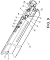
FIG. 9 is diagram showing the slide rail ofFIG. 8 ; -
FIG. 10 is a diagram showing the slide rail of the slide rail device being located at a retracted position relative to the auxiliary component according to an embodiment of the present invention; -
FIG. 11 is a diagram showing an engagement part of the engagement member of the slide rail device ofFIG. 10 passing through a portion of the at least one auxiliary hole of the slide rail; -
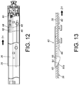
FIG. 12 is a diagram showing the slide rail of the slide rail device being moved relative to the auxiliary component along a first direction according to an embodiment of the present invention; -
FIG. 13 is a diagram showing a portion of the slide rail ofFIG. 12 contacting a disengagement feature of the engagement part of the engagement member; -
FIG. 14 is a diagram showing the slide rail of the slide rail device continuing to move relative to the auxiliary component along the first direction according to an embodiment of the present invention; -
FIG. 15 is a diagram showing the engagement part of the engagement member ofFIG. 14 being disengaged from the auxiliary hole of the slide rail to be adjacent to one side of the slide rail; -
FIG. 16 is a diagram showing the slide rail of the slide rail device being moved to an extension position along the first direction relative to the auxiliary component according to an embodiment of the present invention, wherein a locking member is located at a first position and blocks a mounting math of the slide rail; -
FIG. 17 is a diagram showing the locking member ofFIG. 16 being located at a second position to be away from the mounting path of the slide rail; -
FIG. 18 is a diagram showing the slide rail of the slide rail device ofFIG. 17 being configured to mount the carried object; -
FIG. 19 is a diagram showing the carried object ofFIG. 18 being mounted to the slide rail, and the slide rail being moved relative to the auxiliary component along a second direction; -
FIG. 20 is a diagram showing the slide rail ofFIG. 19 being moved relative to the auxiliary component along the second direction, and a portion of the movable member contacting the engagement part of the engagement member; -
FIG. 21 is a diagram showing the movable member ofFIG. 20 being moved in response to blocking of the engagement part of the engagement member in order to drive the locking member or the operating member to move from the second position back to the first position; -
FIG. 22 is a diagram showing the slide rail being located at the extension position relative to the auxiliary component and the locking member or the operating member being located at the second position according to an embodiment of the present invention; -
FIG. 23 is a diagram showing the locking member or the operating member ofFIG. 22 capable of being manually moved from the second position back to the first position; and -
FIG. 24 is a diagram showing the slide rail ofFIG. 23 being moved relative to the auxiliary component along the second direction. -
FIG. 1 is a diagram showing a pair ofslide rail devices 20 applicable to arack 22 according to an embodiment of the present embodiment. In particular, each of theslide rail devices 20 is mounted to afirst post 24a and asecond post 24b of therack 22. Each of theslide rail devices 20 comprises aslide rail 26. Preferably, theslide rail 26 can be mounted to thefirst post 24a and thesecond post 24b through anauxiliary component 28. Furthermore, theauxiliary component 28 can be a slide rail (such as a fixed rail), a bracket base or the like. Two parts of the auxiliary component 28 (such as a front part and a rear part) can be respectively mounted to thefirst post 24a and thesecond post 24b through afirst bracket 30 and asecond bracket 32. In addition, theslide rail 26 can be located at a retracted position R relative to the auxiliary component28. Preferably, theslide rail device 20 further comprises afastening device 34 connected to theslide rail 26. When theslide rail 26 is located at the retracted position R, thefastening device 34 is adjacent to thefirst post 24a or thefirst bracket 30. - As shown in
FIG. 2 , theslide rail device 20 is configured to mount a carriedobject 36. The carriedobject 36 can be a chassis of an electronic apparatus or a drawer. The carriedobject 36 comprises at least one mounting member (or mounting part). In the present embodiment, the carriedobject 36 comprises a first mountingmember 38a, a second mountingmember 38b and a third mountingmember 38c, for example. The mountingmembers object 36, such as aside part 40. - As shown in
FIG. 3 , each of the mounting members (FIG. 3 only shows the second mountingmember 38b) is protruded from theside part 40. The first mountingmember 38a, the second mountingmember 38b and the third mountingmember 38c are spaced from each other. On the other hand, theslide rail 26 is capable of being moved relative to theauxiliary component 28 from the retracted position R to an extension position E along a first direction D1. Theslide rail 26 is configured to mount the carriedobject 36. Theslide rail 26 comprises a supportingpart 42 and aside wall 44. The supportingpart 42 is substantially perpendicularly connected to theside wall 44. Theslide rail 26 has a mountingpath 46 for allowing the mountingmembers object 36 to pass through, and the supportingpart 42 of theslide rail 26 is configured to support the carriedobject 36. Preferably, the carriedobject 36 further comprises anear part 48 configured to engage with thefastening device 34. As shown inFIG. 4 , thefastening device 34 can be mounted to at least onehole 50 of the first bracket 30 (or thefirst post 24a) . - As shown in
FIG. 5 , one of theslide rail 26 and theauxiliary component 28 has at least one mountinghole 52. In the present embodiment, theside wall 44 of theslide rail 26 has a plurality of mountingholes 52, for example. The plurality of mountingholes 52 are arranged along a longitudinal direction of theslide rail 26 and spaced from each other. Theslide rail device 20 further comprises at least one connectingmember 54 corresponding to the at least one mountinghole 52. In the present embodiment, theslide rail device 20 comprises a plurality of connectingmembers 54, for example. Each of the connectingmembers 54 penetrates through a portion of a corresponding mountinghole 52 to be connected between theauxiliary component 28 and theslide rail 26. - As shown in
FIG. 6 , theauxiliary component 28 has afront part 56 and arear part 58. At least one throughhole 60 is arranged between thefront part 56 and therear part 58 of theauxiliary component 28. In the present embodiment, the at least one throughhole 60 is located adjacent to thefront part 56 of theauxiliary component 28, for example. Theslide rail device 20 further comprises anengagement member 62 mounted to theauxiliary component 28. A portion of theengagement member 62 can be mounted to theauxiliary component 28 by screwing, welding, or engaging. Theengagement member 62 has anelastic part 64 and at least oneengagement part 66 connected to theelastic part 64. The at least oneengagement part 66 can be engaged with the at least one throughhole 60 and face toward theslide rail 26 in response to the elastic force of theelastic part 64. Furthermore, as shown inFIG. 7 , theslide rail 26 comprises at least oneauxiliary hole 68 for allowing theengagement part 66 of theengagement member 62 to pass through. - As shown in
FIG. 8 andFIG.9 , theslide rail 26 has afront part 70 and arear part 72. In the present embodiment, the mountingpath 46 is arranged adjacent to thefront part 70 of theslide rail 26, for example. Preferably, theslide rail 26 has at least one wall section, such as afirst wall section 73a and asecond wall section 73b bent relative to theside wall 44. A mountingpath 46 is formed between thefirst wall section 73a and thesecond wall section 73b. The mountingpath 46 can be an opening or a groove, but not limited thereto. On the other hand, a blockingsection 74 is arranged adjacent to therear part 72 of theslide rail 26. The blockingsection 74 is configured to abut against the carriedobject 36 when the carriedobject 36 is mounted to theslide rail 26. - The
slide rail device 20 further comprises an operatingmember 76 and a lockingmember 78. Preferably, theslide rail device 20 further comprises amovable member 80 and anelastic member 82. - The operating
member 76 is configured to operatively move the lockingmember 78. The operatingmember 76 is movably mounted to theslide rail 26. For example, the operatingmember 76 is pivoted to one of theside wall 44, thefirst wall section 73a and thesecond wall section 73b of theslide rail 26 by afirst shaft member 84. In the present embodiment, thefastening device 34 is mounted to thefirst wall section 73a and thesecond wall section 73b of theslide rail 26 by twofirst shaft members 84. - The locking
member 78 is movably mounted to theslide rail 26. For example, the lockingmember 78 can be pivoted to theside wall 44 of theslide rail 26 by asecond shaft member 86. - The
movable member 80 is movably mounted to theslide rail 26. One of themovable member 80 and theslide wall 44 of theslide rail 26 has anextension hole 88. In the present embodiment, themovable member 80 has theextension hole 88, for example. Theslide rail device 20 further comprises at least one connectingmember 90, such as two connectingmembers 90 penetrating through a portion of theextension hole 88 to be connected between theslide rail 26 and themovable member 80. - The
elastic member 82 is configured to provide an elastic force between the lockingmember 78 and themovable member 80. - As shown in
FIG. 10 and FIG. 11 , when theslide rail 26 is located at the retracted position R relative to theauxiliary component 28, theengagement part 66 of theengagement member 62 is engaged with the throughhole 60 of theauxiliary component 28 and penetrates through a portion of theauxiliary hole 68 of theslide rail 26 in response to the elastic force of theelastic part 64. Preferably, theslide rail 26 comprises afirst hole wall 92a and asecond hole wall 92b. Theauxiliary hole 68 is located between thefirst hole wall 92a and thesecond hole wall 92b. One of theslide rail 26 and theengagement part 66 has a disengagement feature. In the present embodiment, theengagement part 66 has thedisengagement feature 94, for example. Thedisengagement feature 94 can be an inclined face or a curved face. In addition, aportion 96 of themovable member 80 is located between thefirst hole wall 92a and thesecond hole wall 92b and corresponding to theengagement part 66. - As shown in
FIG. 12 and FIG. 13 , when theslide rail 26 is moved relative to theauxiliary component 28 from the retracted position R along the first direction D1, thefirst hole wall 92a of theslide rail 26 contacts thedisengagement feature 94 of theengagement part 66. - As shown in
FIG. 14 and FIG. 15 , when theslide rail 26 continues to move relative to theauxiliary component 28 along the first direction D1, thefirst hole wall 92a of theslide rail 26 abuts against thedisengagement feature 94 of theengagement part 66 of theengagement member 62, in order to disengage theengagement part 66 from theauxiliary hole 68. Since theengagement part 66 is disengaged from theauxiliary hole 68 of theslide rail 26, theengagement part 66 is located adjacent to one side of theslide rail 26 in response to the elastic force of theelastic part 64. - As shown in
FIG. 16 and FIG. 17 , the lockingmember 78 is configured to be located between a first position P1 and a second position P2 relative to the operatingmember 76. When the lockingmember 78 is located at the first position P1, the locking member 78 (or the operating member 76) blocks the mountingpath 46 in order to close the mountingpath 46. In addition, the lockingmember 78 comprises a first abuttingpart 98, and the operatingmember 76 comprises a secondabutting part 100. - When the
slide rail 26 is moved to an extension position E along the first direction D1 relative to theauxiliary component 28, a user can operate the operatingmember 76 to deflect and move the lockingmember 78 from the first position P1 to the second position P2 in response to the operation of the operatingmember 76, and the lockingmember 78 then abuts against the operatingmember 76. For example, the first abuttingpart 98 of the lockingmember 78 abuts against the secondabutting part 100 of the operatingmember 76 in order to hold the locking member 78 (or the operating member 76) at the second position P2. When the lockingmember 78 is located at the second position P2, the locking member 78 (or the operating member 76) is away from the mountingpath 46 in order to open the mountingpath 46. In addition, when the lockingmember 78 is moved from the first position P1 to the second position P2, themovable member 80 is moved along a direction opposite to the first direction D1 in response to the movement of the lockingmember 78. Preferably, through the elastic force of theelastic member 82, the lockingmember 78 can be held at the second position P2 to abut against themovable member 80 and the operatingmember 76. - As shown in
FIG. 18 and FIG. 19 , when the lockingmember 78 is located at the second position P2 (that is to say, the lockingmember 78 and the operatingmember 76 are away from the mounting path 46), the user can mount the carriedobject 36 to theslide rail 26 along a second direction D2. In such mounting process, the plurality of mounting members of the carried object 36 (only the first mountingmember 38a and the third mountingmember 38c are shown inFIG. 18 ) can sequentially pass through the mountingpath 46 of theslide rail 26, and the supportingpart 42 of theslide rail 26 is configured to support the carriedobject 36. When the third mountingmember 38c of the carriedobject 36 passes through the mountingpath 46 of theslide rail 26 along the second direction D2 with the supportingpart 42 of theslide rail 26 supporting the carriedobject 36, the user can apply a force to move theslide rail 26 relative to theauxiliary component 28 from the extension position E toward the retracted position R along the second direction D2. - As shown in
FIG. 20 and FIG. 21 , during the aforementioned moving process, when theauxiliary hole 68 of theslide rail 26 corresponds to theengagement part 66 of theengagement member 62, theengagement part 66 penetrates through theauxiliary hole 68 once again in response to the elastic force of the elastic part 64 (please refer toFIG. 11 ) in order to block themovable member 80. Therefore, when theslide rail 26 continues to move along the second direction D2, themovable member 80 is moved relative to theslide rail 26 along the first direction D1 (the direction opposite to the second direction) in response to the blocking of theengagement part 66, such that themovable member 80 can drive the locking member 78 (or the operating member 76) to move from the second position P2 to the first position P1 in order to block the mountingpath 46 once again. In other words, the lockingmember 78 and the operatingmember 76 can automatically return to an initial state without manual operation (no need to operate the lockingmember 78 and the operating member 76), such that the locking member 78 (or the operating member 76) can close the mountingpath 46 when the lockingmember 78 is located at the first position P1. Therefore, the carriedobject 36 cannot be detached from theslide rail 26. - As shown in
FIG. 22 and FIG. 23 , in another operation mode, when the third mountingmember 38c of the carriedobject 36 passes through the mountingpath 46 of theslide rail 26 with the supportingpart 42 of theslide rail 26 supporting the carriedobject 36, the user can manually operate the operatingmember 76 or the lockingmember 78, in order to move the lockingmember 78 from the second position P2 to the first position P1. Similarly, the mountingpath 46 can be closed as well. - As shown in
FIG. 24 , when the lockingmember 78 is located at the first position P1, the user can apply a force to retract theslide rail 26 relative to theauxiliary component 28 from the extension position E along the second direction.
Claims (15)
- A slide rail device (20), configured to mount a carried object (36), the carried object (36) comprising at least one mounting member (38a, 38b, 38c), the slide rail device (20) comprising:an auxiliary component (28);a slide rail (26) movable relative to the auxiliary component (28), the slide rail (26) having a mounting path (46) for allowing the at least one mounting member (38a, 38b, 38c) of the carried object (36) to pass through;characterized by:an operating member (76); anda locking member (78) movable relative to the operating member (76) between a first position and a second position;wherein when the locking member (78) is located at the first position, the locking member (78) blocks the mounting path (46);wherein when the locking member (78) is located at the second position, the locking member (78) is away from the mounting path (46).
- The slide rail device of claim 1, characterized in that the auxiliary component (28) has a through hole (60), the slide rail device (20) further comprises an engagement member (62) mounted to the auxiliary component (28), the engagement member (62) has an elastic part (64) and an engagement part (66), the engagement part (66) is configured to be engaged with the through hole (60) in response to an elastic force of the elastic part (64).
- The slide rail device of claim 2, characterized in that one of the slide rail (26) and the engagement part (66) has a disengagement feature (94), the disengagement feature (94) comprises an inclined face or a curved face.
- The slide rail device of claim 2 or 3, characterized in that the slide rail (26) comprises an auxiliary hole (68), the engagement part (66) of the engagement member (62) is configured to pass through the auxiliary hole (68) in response to the elastic force of the elastic part (64).
- The slide rail device of claim 4, further characterized by a movable member (80) movably mounted to the slide rail (26), wherein when the slide rail (26) is moved relative to the auxiliary component (28) from an extended position toward a retracted position, the engagement part (66) of the engagement member (62) is configured to block the movable member (80), and the movable member (80) is moved relative to the slide rail (26) in response to the blocking of the engagement part (66), in order to drive the locking member (78) to move from the second position to the first position.
- The slide rail device of claim 1, further characterized by a movable member (80) movably mounted to the slide rail (26), wherein when the locking member (78) is moved from the first position to the second position, the movable member (80) is moved in response to the movement of the locking member (78), and the locking member (78) abuts against the operating member (76).
- The slide rail device of claim 6, further characterized by an elastic member (82) configured to provide an elastic force between the locking member (78) and the movable member (80).
- The slide rail device of claim 6 or 7, characterized in that the locking member (78) comprises a first abutting part (98), the operating member (76) comprises a second abutting part (100), when the operating member (76) is operated, the locking member (78) is moved from the first position toward the second position in response to the operation of the operating member (76), and the first abutting part (98) of the locking member (78) abuts against the second abutting part (100) of the operating member (76) in order to hold the locking member (78) at the second position.
- The slide rail device of any of claims 6-8, characterized by one of the slide rail (26) and the movable member (80) has an extension hole (88), the slide rail device (20) further comprises a connecting member (90) penetrating through a portion of the extension hole (88) to be connected between the slide rail (26) and the movable member (80).
- A slide rail device (20), comprising:a slide rail (26) having a mounting path (46) for allowing at least one mounting member (38a, 38b, 38c) of a carried object (36) to pass through; andcharacterized by:a locking member (78) movably mounted to the slide rail (26);wherein when the locking member (78) is located at a first position, the locking member (78) blocks the mounting path (46);wherein when the locking member (78) is located at a second position, the locking member (78) is away from the mounting path (46).
- The slide rail device of claim 10, further characterized by an operating member (76) configured to operatively move the locking member (78) between the first position and the second position.
- The slide rail device of claim 11, further characterized by a movable member (80) movably mounted to the slide rail (26), wherein when the locking member (78) is moved from the first position to the second position, the movable member (80) is moved in response to the movement of the locking member (78), and the locking member (78) abuts against the operating member (76), the slide rail device (20) further comprises an elastic member (82) configured to provide an elastic force between the locking member (78) and the movable member (80).
- The slide rail device of claim 12, characterized in that the locking member (78) comprises a first abutting part (98), the operating member (76) comprises a second abutting part (100), when the operating member (76) is operated, the locking member (78) is moved from the first position toward the second position in response to the operation of the operating member (76), and the first abutting part (98) of the locking member (78) abuts against the second abutting part (100) of the operating member (76) in order to hold the locking member (78) at the second position.
- A slide rail device (20), configured to mount a carried object (36) to a rack (22), the carried object (36) comprising at least one mounting member (38a, 38b, 38c), the slide rail device (20) comprising:an auxiliary component (28) mounted to the rack (22);a slide rail (26) movable relative to the auxiliary component (28), the slide rail (26) having an auxiliary hole (68) and a mounting path (46), the mounting path (46) configured to allow the at least one mounting member (38a, 38b, 38c) of the carried object (36) to pass through;characterized by:a locking member (78);an operating member (76) configured to operatively move the locking member (78) between a first position and a second position;a movable member (80) movably mounted to the slide rail (26); andan engagement member (62) mounted to the auxiliary component (28), the engagement member (62) having an elastic part (64) and an engagement part (66);wherein when the locking member (78) is located at the first position, one of the locking member (78) and the operating member (76) blocks the mounting path (46);wherein when the locking member (78) is located at the second position, one of the locking member (78) and the operating member (76) is away from the mounting path (46) ;wherein when the locking member (78) is located at the second position and the slide rail (26) is moved relative to the auxiliary component (28) from an extended position toward a retracted position, the engagement part (66) of the engagement member (62) passes through the auxiliary hole (68) of the slide rail (26) in response to the elastic force of the elastic part (64) to block the movable member (80), and the movable member (80) is moved relative to the slide rail (26) in response to the blocking of the engagement part (66), in order to drive one of the locking member (78) and the operating member (76) to move from the second position to the first position.
- The slide rail device of claim 14, further characterized by an elastic member (82) configured to provide an elastic force between the locking member (78) and the movable member (80).
Applications Claiming Priority (1)
| Application Number | Priority Date | Filing Date | Title |
|---|---|---|---|
| TW105117119A TWI594711B (en) | 2016-05-31 | 2016-05-31 | Slide rail device |
Publications (2)
| Publication Number | Publication Date |
|---|---|
| EP3253189A1 true EP3253189A1 (en) | 2017-12-06 |
| EP3253189B1 EP3253189B1 (en) | 2019-09-11 |
Family
ID=57485361
Family Applications (1)
| Application Number | Title | Priority Date | Filing Date |
|---|---|---|---|
| EP16202131.5A Active EP3253189B1 (en) | 2016-05-31 | 2016-12-05 | Slide rail device |
Country Status (4)
| Country | Link |
|---|---|
| US (1) | US9867462B2 (en) |
| EP (1) | EP3253189B1 (en) |
| JP (1) | JP6310995B2 (en) |
| TW (1) | TWI594711B (en) |
Cited By (1)
| Publication number | Priority date | Publication date | Assignee | Title |
|---|---|---|---|---|
| US10806255B1 (en) | 2019-06-12 | 2020-10-20 | King Slide Works Co., Ltd. | Slide rail assembly |
Families Citing this family (12)
| Publication number | Priority date | Publication date | Assignee | Title |
|---|---|---|---|---|
| TWI600394B (en) | 2016-07-19 | 2017-10-01 | 川湖科技股份有限公司 | Slide rail assembly for use in a rack system |
| DE102017106602A1 (en) * | 2017-03-28 | 2018-10-04 | Deutsche Post Ag | General cargo box and procedure for the transfer and storage of general cargo in a general cargo box |
| US10356931B1 (en) * | 2017-05-26 | 2019-07-16 | King Slide Works Co., Ltd. | Rack mounting system |
| TWI642385B (en) | 2017-08-31 | 2018-12-01 | 川湖科技股份有限公司 | Slide rail assembly and slide rail mechanism thereof |
| TWI640275B (en) * | 2017-09-15 | 2018-11-11 | 川湖科技股份有限公司 | Rack system and slide rail assembly thereof |
| CN109526174B (en) * | 2017-09-20 | 2020-07-07 | 川湖科技股份有限公司 | Rack system and slide rail assembly thereof |
| TWI642387B (en) * | 2017-11-13 | 2018-12-01 | 川湖科技股份有限公司 | Slide rail rack system and carried object thereof |
| TWI703917B (en) | 2019-12-23 | 2020-09-01 | 川湖科技股份有限公司 | Rack system and slide rail mechanism thereof |
| TWI829509B (en) * | 2023-01-13 | 2024-01-11 | 川湖科技股份有限公司 | Slide rail assembly |
| TWI842561B (en) * | 2023-06-08 | 2024-05-11 | 川湖科技股份有限公司 | Slide rail assembly |
| TWI842640B (en) * | 2023-10-12 | 2024-05-11 | 川湖科技股份有限公司 | Slide rail assembly |
| TWI847902B (en) * | 2023-10-30 | 2024-07-01 | 川湖科技股份有限公司 | Slide rail assembly |
Citations (5)
| Publication number | Priority date | Publication date | Assignee | Title |
|---|---|---|---|---|
| US6220456B1 (en) | 2000-04-19 | 2001-04-24 | Dell Products, L.P. | Method and apparatus for supporting a computer chassis |
| US6601933B1 (en) * | 2002-06-21 | 2003-08-05 | General Devices Co., Inc. | Telescoping slide with quick-mount system |
| US20090072689A1 (en) * | 2005-07-22 | 2009-03-19 | Shun-Ho Yang | Fast Mounting Mechanism for a telescoping slide |
| US20090289155A1 (en) * | 2008-05-23 | 2009-11-26 | Hong Fu Jin Precision Industry (Shenzhen) Co., Ltd | Slide rail assembly |
| US8366217B1 (en) * | 2012-01-23 | 2013-02-05 | King Slide Works Co., Ltd. | Installation device for slide assembly |
Family Cites Families (6)
| Publication number | Priority date | Publication date | Assignee | Title |
|---|---|---|---|---|
| JP3617980B2 (en) * | 2002-06-06 | 2005-02-09 | 株式会社東芝 | Slide rail and rack |
| US6945619B1 (en) * | 2004-08-13 | 2005-09-20 | King Slide Works Co., Ltd. | Positioning device for a slide |
| US7758134B2 (en) * | 2007-08-28 | 2010-07-20 | Nan Juen International Co., Ltd. | Drawer fixing apparatus |
| US8127940B2 (en) | 2008-12-08 | 2012-03-06 | Dell Products L.P. | Rail including a shelf for supporting an information handling system |
| JP5565854B2 (en) * | 2009-10-27 | 2014-08-06 | エヌイーシーコンピュータテクノ株式会社 | Slide rail unit, rack cabinet, removal tool, and removal method |
| JP3189813U (en) * | 2014-01-20 | 2014-04-03 | 川湖科技股▲分▼有限公司 | Bracket device and slide rail assembly |
-
2016
- 2016-05-31 TW TW105117119A patent/TWI594711B/en active
- 2016-11-02 US US15/342,090 patent/US9867462B2/en active Active
- 2016-11-18 JP JP2016224600A patent/JP6310995B2/en active Active
- 2016-12-05 EP EP16202131.5A patent/EP3253189B1/en active Active
Patent Citations (5)
| Publication number | Priority date | Publication date | Assignee | Title |
|---|---|---|---|---|
| US6220456B1 (en) | 2000-04-19 | 2001-04-24 | Dell Products, L.P. | Method and apparatus for supporting a computer chassis |
| US6601933B1 (en) * | 2002-06-21 | 2003-08-05 | General Devices Co., Inc. | Telescoping slide with quick-mount system |
| US20090072689A1 (en) * | 2005-07-22 | 2009-03-19 | Shun-Ho Yang | Fast Mounting Mechanism for a telescoping slide |
| US20090289155A1 (en) * | 2008-05-23 | 2009-11-26 | Hong Fu Jin Precision Industry (Shenzhen) Co., Ltd | Slide rail assembly |
| US8366217B1 (en) * | 2012-01-23 | 2013-02-05 | King Slide Works Co., Ltd. | Installation device for slide assembly |
Cited By (2)
| Publication number | Priority date | Publication date | Assignee | Title |
|---|---|---|---|---|
| US10806255B1 (en) | 2019-06-12 | 2020-10-20 | King Slide Works Co., Ltd. | Slide rail assembly |
| EP3750446A1 (en) * | 2019-06-12 | 2020-12-16 | King Slide Works Co., Ltd. | Slide rail assembly |
Also Published As
| Publication number | Publication date |
|---|---|
| TW201740836A (en) | 2017-12-01 |
| US20170340109A1 (en) | 2017-11-30 |
| US9867462B2 (en) | 2018-01-16 |
| TWI594711B (en) | 2017-08-11 |
| EP3253189B1 (en) | 2019-09-11 |
| JP6310995B2 (en) | 2018-04-11 |
| JP2017216426A (en) | 2017-12-07 |
Similar Documents
| Publication | Publication Date | Title |
|---|---|---|
| EP3253189B1 (en) | Slide rail device | |
| US10455938B2 (en) | Slide rail assembly | |
| EP3322269B1 (en) | Bracket device and slide rail assembly comprising the same | |
| CN101606789B (en) | Sliding rail fixing device | |
| EP3068199B1 (en) | Slide rail assembly | |
| EP3398481B1 (en) | Slide rail assembly | |
| EP3275338A1 (en) | Slide rail assembly | |
| EP3144457B1 (en) | Rack system with a slide rail assembly with interlock device | |
| EP3143901B1 (en) | Slide rail assembly | |
| EP3300348A1 (en) | Rail mounting adapter assembly for rack | |
| EP3440961A1 (en) | Slide rail assembly and rail kit thereof | |
| EP3135156A1 (en) | Slide rail assembly | |
| EP3292789A1 (en) | Slide rail assembly and rail kit thereof | |
| US20180070724A1 (en) | Bracket device | |
| US10342336B2 (en) | Bracket device | |
| EP3193569A1 (en) | Bracket device | |
| EP2893838A1 (en) | Adjustable bracket assembly and slide assembly comprising the same | |
| EP3310033A1 (en) | Slide rail assembly | |
| EP3269274A1 (en) | Slide rail assembly | |
| EP3136694B1 (en) | Housing mounting mechanism for portable electronic device | |
| EP3387951A1 (en) | Clutch for furniture parts | |
| EP2874478B1 (en) | Slide rail assembly for rack system | |
| CN107027262A (en) | Bracket device |
Legal Events
| Date | Code | Title | Description |
|---|---|---|---|
| PUAI | Public reference made under article 153(3) epc to a published international application that has entered the european phase |
Free format text: ORIGINAL CODE: 0009012 |
|
| STAA | Information on the status of an ep patent application or granted ep patent |
Free format text: STATUS: THE APPLICATION HAS BEEN PUBLISHED |
|
| AK | Designated contracting states |
Kind code of ref document: A1 Designated state(s): AL AT BE BG CH CY CZ DE DK EE ES FI FR GB GR HR HU IE IS IT LI LT LU LV MC MK MT NL NO PL PT RO RS SE SI SK SM TR |
|
| AX | Request for extension of the european patent |
Extension state: BA ME |
|
| STAA | Information on the status of an ep patent application or granted ep patent |
Free format text: STATUS: REQUEST FOR EXAMINATION WAS MADE |
|
| 17P | Request for examination filed |
Effective date: 20180528 |
|
| RBV | Designated contracting states (corrected) |
Designated state(s): AL AT BE BG CH CY CZ DE DK EE ES FI FR GB GR HR HU IE IS IT LI LT LU LV MC MK MT NL NO PL PT RO RS SE SI SK SM TR |
|
| GRAP | Despatch of communication of intention to grant a patent |
Free format text: ORIGINAL CODE: EPIDOSNIGR1 |
|
| STAA | Information on the status of an ep patent application or granted ep patent |
Free format text: STATUS: GRANT OF PATENT IS INTENDED |
|
| RIC1 | Information provided on ipc code assigned before grant |
Ipc: G06F 1/16 20060101ALI20190327BHEP Ipc: A47B 88/427 20170101ALI20190327BHEP Ipc: A47B 88/423 20170101ALI20190327BHEP Ipc: H05K 7/18 20060101ALI20190327BHEP Ipc: H05K 7/14 20060101AFI20190327BHEP |
|
| INTG | Intention to grant announced |
Effective date: 20190410 |
|
| GRAS | Grant fee paid |
Free format text: ORIGINAL CODE: EPIDOSNIGR3 |
|
| GRAA | (expected) grant |
Free format text: ORIGINAL CODE: 0009210 |
|
| STAA | Information on the status of an ep patent application or granted ep patent |
Free format text: STATUS: THE PATENT HAS BEEN GRANTED |
|
| AK | Designated contracting states |
Kind code of ref document: B1 Designated state(s): AL AT BE BG CH CY CZ DE DK EE ES FI FR GB GR HR HU IE IS IT LI LT LU LV MC MK MT NL NO PL PT RO RS SE SI SK SM TR |
|
| REG | Reference to a national code |
Ref country code: GB Ref legal event code: FG4D |
|
| REG | Reference to a national code |
Ref country code: CH Ref legal event code: EP |
|
| REG | Reference to a national code |
Ref country code: AT Ref legal event code: REF Ref document number: 1180201 Country of ref document: AT Kind code of ref document: T Effective date: 20190915 |
|
| REG | Reference to a national code |
Ref country code: DE Ref legal event code: R096 Ref document number: 602016020308 Country of ref document: DE Ref country code: IE Ref legal event code: FG4D |
|
| REG | Reference to a national code |
Ref country code: DE Ref legal event code: R082 Ref document number: 602016020308 Country of ref document: DE Representative=s name: STRAUS, ALEXANDER, DIPL.-CHEM.UNIV. DR.PHIL., DE Ref country code: DE Ref legal event code: R082 Ref document number: 602016020308 Country of ref document: DE Representative=s name: 2K PATENT- UND RECHTSANWAELTE PARTNERSCHAFT MB, DE |
|
| REG | Reference to a national code |
Ref country code: NL Ref legal event code: MP Effective date: 20190911 |
|
| REG | Reference to a national code |
Ref country code: LT Ref legal event code: MG4D |
|
| PG25 | Lapsed in a contracting state [announced via postgrant information from national office to epo] |
Ref country code: HR Free format text: LAPSE BECAUSE OF FAILURE TO SUBMIT A TRANSLATION OF THE DESCRIPTION OR TO PAY THE FEE WITHIN THE PRESCRIBED TIME-LIMIT Effective date: 20190911 Ref country code: LT Free format text: LAPSE BECAUSE OF FAILURE TO SUBMIT A TRANSLATION OF THE DESCRIPTION OR TO PAY THE FEE WITHIN THE PRESCRIBED TIME-LIMIT Effective date: 20190911 Ref country code: FI Free format text: LAPSE BECAUSE OF FAILURE TO SUBMIT A TRANSLATION OF THE DESCRIPTION OR TO PAY THE FEE WITHIN THE PRESCRIBED TIME-LIMIT Effective date: 20190911 Ref country code: SE Free format text: LAPSE BECAUSE OF FAILURE TO SUBMIT A TRANSLATION OF THE DESCRIPTION OR TO PAY THE FEE WITHIN THE PRESCRIBED TIME-LIMIT Effective date: 20190911 Ref country code: NO Free format text: LAPSE BECAUSE OF FAILURE TO SUBMIT A TRANSLATION OF THE DESCRIPTION OR TO PAY THE FEE WITHIN THE PRESCRIBED TIME-LIMIT Effective date: 20191211 Ref country code: BG Free format text: LAPSE BECAUSE OF FAILURE TO SUBMIT A TRANSLATION OF THE DESCRIPTION OR TO PAY THE FEE WITHIN THE PRESCRIBED TIME-LIMIT Effective date: 20191211 |
|
| PG25 | Lapsed in a contracting state [announced via postgrant information from national office to epo] |
Ref country code: RS Free format text: LAPSE BECAUSE OF FAILURE TO SUBMIT A TRANSLATION OF THE DESCRIPTION OR TO PAY THE FEE WITHIN THE PRESCRIBED TIME-LIMIT Effective date: 20190911 Ref country code: LV Free format text: LAPSE BECAUSE OF FAILURE TO SUBMIT A TRANSLATION OF THE DESCRIPTION OR TO PAY THE FEE WITHIN THE PRESCRIBED TIME-LIMIT Effective date: 20190911 Ref country code: ES Free format text: LAPSE BECAUSE OF FAILURE TO SUBMIT A TRANSLATION OF THE DESCRIPTION OR TO PAY THE FEE WITHIN THE PRESCRIBED TIME-LIMIT Effective date: 20190911 Ref country code: AL Free format text: LAPSE BECAUSE OF FAILURE TO SUBMIT A TRANSLATION OF THE DESCRIPTION OR TO PAY THE FEE WITHIN THE PRESCRIBED TIME-LIMIT Effective date: 20190911 Ref country code: GR Free format text: LAPSE BECAUSE OF FAILURE TO SUBMIT A TRANSLATION OF THE DESCRIPTION OR TO PAY THE FEE WITHIN THE PRESCRIBED TIME-LIMIT Effective date: 20191212 |
|
| REG | Reference to a national code |
Ref country code: AT Ref legal event code: MK05 Ref document number: 1180201 Country of ref document: AT Kind code of ref document: T Effective date: 20190911 |
|
| PG25 | Lapsed in a contracting state [announced via postgrant information from national office to epo] |
Ref country code: NL Free format text: LAPSE BECAUSE OF FAILURE TO SUBMIT A TRANSLATION OF THE DESCRIPTION OR TO PAY THE FEE WITHIN THE PRESCRIBED TIME-LIMIT Effective date: 20190911 Ref country code: AT Free format text: LAPSE BECAUSE OF FAILURE TO SUBMIT A TRANSLATION OF THE DESCRIPTION OR TO PAY THE FEE WITHIN THE PRESCRIBED TIME-LIMIT Effective date: 20190911 Ref country code: PT Free format text: LAPSE BECAUSE OF FAILURE TO SUBMIT A TRANSLATION OF THE DESCRIPTION OR TO PAY THE FEE WITHIN THE PRESCRIBED TIME-LIMIT Effective date: 20200113 Ref country code: PL Free format text: LAPSE BECAUSE OF FAILURE TO SUBMIT A TRANSLATION OF THE DESCRIPTION OR TO PAY THE FEE WITHIN THE PRESCRIBED TIME-LIMIT Effective date: 20190911 Ref country code: IT Free format text: LAPSE BECAUSE OF FAILURE TO SUBMIT A TRANSLATION OF THE DESCRIPTION OR TO PAY THE FEE WITHIN THE PRESCRIBED TIME-LIMIT Effective date: 20190911 Ref country code: RO Free format text: LAPSE BECAUSE OF FAILURE TO SUBMIT A TRANSLATION OF THE DESCRIPTION OR TO PAY THE FEE WITHIN THE PRESCRIBED TIME-LIMIT Effective date: 20190911 Ref country code: EE Free format text: LAPSE BECAUSE OF FAILURE TO SUBMIT A TRANSLATION OF THE DESCRIPTION OR TO PAY THE FEE WITHIN THE PRESCRIBED TIME-LIMIT Effective date: 20190911 |
|
| PG25 | Lapsed in a contracting state [announced via postgrant information from national office to epo] |
Ref country code: SM Free format text: LAPSE BECAUSE OF FAILURE TO SUBMIT A TRANSLATION OF THE DESCRIPTION OR TO PAY THE FEE WITHIN THE PRESCRIBED TIME-LIMIT Effective date: 20190911 Ref country code: CZ Free format text: LAPSE BECAUSE OF FAILURE TO SUBMIT A TRANSLATION OF THE DESCRIPTION OR TO PAY THE FEE WITHIN THE PRESCRIBED TIME-LIMIT Effective date: 20190911 Ref country code: IS Free format text: LAPSE BECAUSE OF FAILURE TO SUBMIT A TRANSLATION OF THE DESCRIPTION OR TO PAY THE FEE WITHIN THE PRESCRIBED TIME-LIMIT Effective date: 20200224 Ref country code: SK Free format text: LAPSE BECAUSE OF FAILURE TO SUBMIT A TRANSLATION OF THE DESCRIPTION OR TO PAY THE FEE WITHIN THE PRESCRIBED TIME-LIMIT Effective date: 20190911 |
|
| REG | Reference to a national code |
Ref country code: DE Ref legal event code: R097 Ref document number: 602016020308 Country of ref document: DE |
|
| PLBE | No opposition filed within time limit |
Free format text: ORIGINAL CODE: 0009261 |
|
| STAA | Information on the status of an ep patent application or granted ep patent |
Free format text: STATUS: NO OPPOSITION FILED WITHIN TIME LIMIT |
|
| PG2D | Information on lapse in contracting state deleted |
Ref country code: IS |
|
| PG25 | Lapsed in a contracting state [announced via postgrant information from national office to epo] |
Ref country code: DK Free format text: LAPSE BECAUSE OF FAILURE TO SUBMIT A TRANSLATION OF THE DESCRIPTION OR TO PAY THE FEE WITHIN THE PRESCRIBED TIME-LIMIT Effective date: 20190911 Ref country code: IS Free format text: LAPSE BECAUSE OF FAILURE TO SUBMIT A TRANSLATION OF THE DESCRIPTION OR TO PAY THE FEE WITHIN THE PRESCRIBED TIME-LIMIT Effective date: 20200112 |
|
| REG | Reference to a national code |
Ref country code: CH Ref legal event code: PL |
|
| 26N | No opposition filed |
Effective date: 20200615 |
|
| REG | Reference to a national code |
Ref country code: BE Ref legal event code: MM Effective date: 20191231 |
|
| PG25 | Lapsed in a contracting state [announced via postgrant information from national office to epo] |
Ref country code: MC Free format text: LAPSE BECAUSE OF FAILURE TO SUBMIT A TRANSLATION OF THE DESCRIPTION OR TO PAY THE FEE WITHIN THE PRESCRIBED TIME-LIMIT Effective date: 20190911 Ref country code: SI Free format text: LAPSE BECAUSE OF FAILURE TO SUBMIT A TRANSLATION OF THE DESCRIPTION OR TO PAY THE FEE WITHIN THE PRESCRIBED TIME-LIMIT Effective date: 20190911 |
|
| PG25 | Lapsed in a contracting state [announced via postgrant information from national office to epo] |
Ref country code: FR Free format text: LAPSE BECAUSE OF NON-PAYMENT OF DUE FEES Effective date: 20191231 Ref country code: LU Free format text: LAPSE BECAUSE OF NON-PAYMENT OF DUE FEES Effective date: 20191205 |
|
| PG25 | Lapsed in a contracting state [announced via postgrant information from national office to epo] |
Ref country code: LI Free format text: LAPSE BECAUSE OF NON-PAYMENT OF DUE FEES Effective date: 20191231 Ref country code: CH Free format text: LAPSE BECAUSE OF NON-PAYMENT OF DUE FEES Effective date: 20191231 Ref country code: BE Free format text: LAPSE BECAUSE OF NON-PAYMENT OF DUE FEES Effective date: 20191231 |
|
| PG25 | Lapsed in a contracting state [announced via postgrant information from national office to epo] |
Ref country code: CY Free format text: LAPSE BECAUSE OF FAILURE TO SUBMIT A TRANSLATION OF THE DESCRIPTION OR TO PAY THE FEE WITHIN THE PRESCRIBED TIME-LIMIT Effective date: 20190911 |
|
| PG25 | Lapsed in a contracting state [announced via postgrant information from national office to epo] |
Ref country code: HU Free format text: LAPSE BECAUSE OF FAILURE TO SUBMIT A TRANSLATION OF THE DESCRIPTION OR TO PAY THE FEE WITHIN THE PRESCRIBED TIME-LIMIT; INVALID AB INITIO Effective date: 20161205 Ref country code: MT Free format text: LAPSE BECAUSE OF FAILURE TO SUBMIT A TRANSLATION OF THE DESCRIPTION OR TO PAY THE FEE WITHIN THE PRESCRIBED TIME-LIMIT Effective date: 20190911 |
|
| PG25 | Lapsed in a contracting state [announced via postgrant information from national office to epo] |
Ref country code: TR Free format text: LAPSE BECAUSE OF FAILURE TO SUBMIT A TRANSLATION OF THE DESCRIPTION OR TO PAY THE FEE WITHIN THE PRESCRIBED TIME-LIMIT Effective date: 20190911 |
|
| PG25 | Lapsed in a contracting state [announced via postgrant information from national office to epo] |
Ref country code: MK Free format text: LAPSE BECAUSE OF FAILURE TO SUBMIT A TRANSLATION OF THE DESCRIPTION OR TO PAY THE FEE WITHIN THE PRESCRIBED TIME-LIMIT Effective date: 20190911 |
|
| REG | Reference to a national code |
Ref country code: DE Ref legal event code: R082 Ref document number: 602016020308 Country of ref document: DE Representative=s name: STRAUS, ALEXANDER, DIPL.-CHEM.UNIV. DR.PHIL., DE |
|
| PGFP | Annual fee paid to national office [announced via postgrant information from national office to epo] |
Ref country code: DE Payment date: 20251013 Year of fee payment: 10 |
|
| PGFP | Annual fee paid to national office [announced via postgrant information from national office to epo] |
Ref country code: GB Payment date: 20251008 Year of fee payment: 10 |
|
| PGFP | Annual fee paid to national office [announced via postgrant information from national office to epo] |
Ref country code: IE Payment date: 20251008 Year of fee payment: 10 |