EP3253075A1 - Hörgerät mit strahlformerfiltrierungseinheit mit einer glättungseinheit - Google Patents
Hörgerät mit strahlformerfiltrierungseinheit mit einer glättungseinheit Download PDFInfo
- Publication number
- EP3253075A1 EP3253075A1 EP17173422.1A EP17173422A EP3253075A1 EP 3253075 A1 EP3253075 A1 EP 3253075A1 EP 17173422 A EP17173422 A EP 17173422A EP 3253075 A1 EP3253075 A1 EP 3253075A1
- Authority
- EP
- European Patent Office
- Prior art keywords
- hearing aid
- smoothing
- complex
- providing
- resulting
- Prior art date
- Legal status (The legal status is an assumption and is not a legal conclusion. Google has not performed a legal analysis and makes no representation as to the accuracy of the status listed.)
- Granted
Links
- 238000009499 grossing Methods 0.000 title claims abstract description 149
- 238000001914 filtration Methods 0.000 title claims abstract description 38
- 230000003044 adaptive effect Effects 0.000 claims abstract description 81
- 230000006978 adaptation Effects 0.000 claims abstract description 55
- 230000014509 gene expression Effects 0.000 claims abstract description 53
- 230000001419 dependent effect Effects 0.000 claims abstract description 52
- 238000000034 method Methods 0.000 claims abstract description 42
- 239000011159 matrix material Substances 0.000 claims abstract description 36
- 238000012545 processing Methods 0.000 claims abstract description 35
- 230000021615 conjugation Effects 0.000 claims abstract description 8
- 230000017105 transposition Effects 0.000 claims abstract description 7
- 230000006870 function Effects 0.000 claims description 33
- 230000003247 decreasing effect Effects 0.000 claims description 5
- 238000012886 linear function Methods 0.000 claims description 4
- 238000010586 diagram Methods 0.000 description 21
- 230000005236 sound signal Effects 0.000 description 21
- 230000008859 change Effects 0.000 description 17
- 210000000613 ear canal Anatomy 0.000 description 12
- 230000008901 benefit Effects 0.000 description 10
- 210000003128 head Anatomy 0.000 description 9
- 238000004891 communication Methods 0.000 description 8
- 230000000694 effects Effects 0.000 description 8
- 238000004458 analytical method Methods 0.000 description 7
- 230000008569 process Effects 0.000 description 6
- 238000006243 chemical reaction Methods 0.000 description 5
- 238000004590 computer program Methods 0.000 description 5
- 230000001965 increasing effect Effects 0.000 description 5
- 238000012935 Averaging Methods 0.000 description 4
- 208000016354 hearing loss disease Diseases 0.000 description 4
- 230000003595 spectral effect Effects 0.000 description 4
- 230000009286 beneficial effect Effects 0.000 description 3
- 210000003477 cochlea Anatomy 0.000 description 3
- 230000006835 compression Effects 0.000 description 3
- 238000007906 compression Methods 0.000 description 3
- 210000000959 ear middle Anatomy 0.000 description 3
- 210000005069 ears Anatomy 0.000 description 3
- 230000002708 enhancing effect Effects 0.000 description 3
- 210000003625 skull Anatomy 0.000 description 3
- 238000012546 transfer Methods 0.000 description 3
- 230000005540 biological transmission Effects 0.000 description 2
- 210000000988 bone and bone Anatomy 0.000 description 2
- 238000004422 calculation algorithm Methods 0.000 description 2
- 238000004364 calculation method Methods 0.000 description 2
- 210000003027 ear inner Anatomy 0.000 description 2
- 238000013507 mapping Methods 0.000 description 2
- 230000003287 optical effect Effects 0.000 description 2
- 238000005070 sampling Methods 0.000 description 2
- 238000007493 shaping process Methods 0.000 description 2
- 239000000758 substrate Substances 0.000 description 2
- 210000003454 tympanic membrane Anatomy 0.000 description 2
- 101100434663 Bacillus subtilis (strain 168) fbaA gene Proteins 0.000 description 1
- 101150095274 FBA1 gene Proteins 0.000 description 1
- 101150055254 FBA2 gene Proteins 0.000 description 1
- 208000032041 Hearing impaired Diseases 0.000 description 1
- 101000802640 Homo sapiens Lactosylceramide 4-alpha-galactosyltransferase Proteins 0.000 description 1
- 102100035838 Lactosylceramide 4-alpha-galactosyltransferase Human genes 0.000 description 1
- 239000000654 additive Substances 0.000 description 1
- 230000000996 additive effect Effects 0.000 description 1
- 238000012884 algebraic function Methods 0.000 description 1
- 230000003321 amplification Effects 0.000 description 1
- 238000003491 array Methods 0.000 description 1
- 210000003926 auditory cortex Anatomy 0.000 description 1
- 230000003190 augmentative effect Effects 0.000 description 1
- 230000015572 biosynthetic process Effects 0.000 description 1
- 239000003990 capacitor Substances 0.000 description 1
- 210000003710 cerebral cortex Anatomy 0.000 description 1
- 210000000860 cochlear nerve Anatomy 0.000 description 1
- 230000001427 coherent effect Effects 0.000 description 1
- 239000004020 conductor Substances 0.000 description 1
- 230000007423 decrease Effects 0.000 description 1
- 238000013461 design Methods 0.000 description 1
- 238000001514 detection method Methods 0.000 description 1
- 210000000883 ear external Anatomy 0.000 description 1
- 238000005516 engineering process Methods 0.000 description 1
- 210000002768 hair cell Anatomy 0.000 description 1
- 239000007943 implant Substances 0.000 description 1
- 230000003993 interaction Effects 0.000 description 1
- 239000007788 liquid Substances 0.000 description 1
- 239000000203 mixture Substances 0.000 description 1
- 238000012986 modification Methods 0.000 description 1
- 230000004048 modification Effects 0.000 description 1
- 210000005036 nerve Anatomy 0.000 description 1
- 238000003199 nucleic acid amplification method Methods 0.000 description 1
- 230000009467 reduction Effects 0.000 description 1
- 230000001629 suppression Effects 0.000 description 1
- 238000003786 synthesis reaction Methods 0.000 description 1
- 230000009466 transformation Effects 0.000 description 1
Images


Classifications
-
- H—ELECTRICITY
- H04—ELECTRIC COMMUNICATION TECHNIQUE
- H04R—LOUDSPEAKERS, MICROPHONES, GRAMOPHONE PICK-UPS OR LIKE ACOUSTIC ELECTROMECHANICAL TRANSDUCERS; DEAF-AID SETS; PUBLIC ADDRESS SYSTEMS
- H04R25/00—Deaf-aid sets, i.e. electro-acoustic or electro-mechanical hearing aids; Electric tinnitus maskers providing an auditory perception
- H04R25/40—Arrangements for obtaining a desired directivity characteristic
- H04R25/407—Circuits for combining signals of a plurality of transducers
-
- G—PHYSICS
- G10—MUSICAL INSTRUMENTS; ACOUSTICS
- G10L—SPEECH ANALYSIS TECHNIQUES OR SPEECH SYNTHESIS; SPEECH RECOGNITION; SPEECH OR VOICE PROCESSING TECHNIQUES; SPEECH OR AUDIO CODING OR DECODING
- G10L21/00—Speech or voice signal processing techniques to produce another audible or non-audible signal, e.g. visual or tactile, in order to modify its quality or its intelligibility
- G10L21/02—Speech enhancement, e.g. noise reduction or echo cancellation
- G10L21/0208—Noise filtering
-
- H—ELECTRICITY
- H04—ELECTRIC COMMUNICATION TECHNIQUE
- H04R—LOUDSPEAKERS, MICROPHONES, GRAMOPHONE PICK-UPS OR LIKE ACOUSTIC ELECTROMECHANICAL TRANSDUCERS; DEAF-AID SETS; PUBLIC ADDRESS SYSTEMS
- H04R25/00—Deaf-aid sets, i.e. electro-acoustic or electro-mechanical hearing aids; Electric tinnitus maskers providing an auditory perception
- H04R25/30—Monitoring or testing of hearing aids, e.g. functioning, settings, battery power
- H04R25/305—Self-monitoring or self-testing
-
- H—ELECTRICITY
- H04—ELECTRIC COMMUNICATION TECHNIQUE
- H04R—LOUDSPEAKERS, MICROPHONES, GRAMOPHONE PICK-UPS OR LIKE ACOUSTIC ELECTROMECHANICAL TRANSDUCERS; DEAF-AID SETS; PUBLIC ADDRESS SYSTEMS
- H04R25/00—Deaf-aid sets, i.e. electro-acoustic or electro-mechanical hearing aids; Electric tinnitus maskers providing an auditory perception
- H04R25/35—Deaf-aid sets, i.e. electro-acoustic or electro-mechanical hearing aids; Electric tinnitus maskers providing an auditory perception using translation techniques
-
- H—ELECTRICITY
- H04—ELECTRIC COMMUNICATION TECHNIQUE
- H04R—LOUDSPEAKERS, MICROPHONES, GRAMOPHONE PICK-UPS OR LIKE ACOUSTIC ELECTROMECHANICAL TRANSDUCERS; DEAF-AID SETS; PUBLIC ADDRESS SYSTEMS
- H04R25/00—Deaf-aid sets, i.e. electro-acoustic or electro-mechanical hearing aids; Electric tinnitus maskers providing an auditory perception
- H04R25/40—Arrangements for obtaining a desired directivity characteristic
- H04R25/405—Arrangements for obtaining a desired directivity characteristic by combining a plurality of transducers
-
- H—ELECTRICITY
- H04—ELECTRIC COMMUNICATION TECHNIQUE
- H04R—LOUDSPEAKERS, MICROPHONES, GRAMOPHONE PICK-UPS OR LIKE ACOUSTIC ELECTROMECHANICAL TRANSDUCERS; DEAF-AID SETS; PUBLIC ADDRESS SYSTEMS
- H04R25/00—Deaf-aid sets, i.e. electro-acoustic or electro-mechanical hearing aids; Electric tinnitus maskers providing an auditory perception
- H04R25/50—Customised settings for obtaining desired overall acoustical characteristics
- H04R25/502—Customised settings for obtaining desired overall acoustical characteristics using analog signal processing
-
- H—ELECTRICITY
- H04—ELECTRIC COMMUNICATION TECHNIQUE
- H04R—LOUDSPEAKERS, MICROPHONES, GRAMOPHONE PICK-UPS OR LIKE ACOUSTIC ELECTROMECHANICAL TRANSDUCERS; DEAF-AID SETS; PUBLIC ADDRESS SYSTEMS
- H04R25/00—Deaf-aid sets, i.e. electro-acoustic or electro-mechanical hearing aids; Electric tinnitus maskers providing an auditory perception
- H04R25/50—Customised settings for obtaining desired overall acoustical characteristics
- H04R25/505—Customised settings for obtaining desired overall acoustical characteristics using digital signal processing
-
- H—ELECTRICITY
- H04—ELECTRIC COMMUNICATION TECHNIQUE
- H04R—LOUDSPEAKERS, MICROPHONES, GRAMOPHONE PICK-UPS OR LIKE ACOUSTIC ELECTROMECHANICAL TRANSDUCERS; DEAF-AID SETS; PUBLIC ADDRESS SYSTEMS
- H04R25/00—Deaf-aid sets, i.e. electro-acoustic or electro-mechanical hearing aids; Electric tinnitus maskers providing an auditory perception
- H04R25/55—Deaf-aid sets, i.e. electro-acoustic or electro-mechanical hearing aids; Electric tinnitus maskers providing an auditory perception using an external connection, either wireless or wired
-
- H—ELECTRICITY
- H04—ELECTRIC COMMUNICATION TECHNIQUE
- H04R—LOUDSPEAKERS, MICROPHONES, GRAMOPHONE PICK-UPS OR LIKE ACOUSTIC ELECTROMECHANICAL TRANSDUCERS; DEAF-AID SETS; PUBLIC ADDRESS SYSTEMS
- H04R25/00—Deaf-aid sets, i.e. electro-acoustic or electro-mechanical hearing aids; Electric tinnitus maskers providing an auditory perception
- H04R25/70—Adaptation of deaf aid to hearing loss, e.g. initial electronic fitting
-
- H—ELECTRICITY
- H04—ELECTRIC COMMUNICATION TECHNIQUE
- H04R—LOUDSPEAKERS, MICROPHONES, GRAMOPHONE PICK-UPS OR LIKE ACOUSTIC ELECTROMECHANICAL TRANSDUCERS; DEAF-AID SETS; PUBLIC ADDRESS SYSTEMS
- H04R3/00—Circuits for transducers, loudspeakers or microphones
- H04R3/005—Circuits for transducers, loudspeakers or microphones for combining the signals of two or more microphones
-
- H—ELECTRICITY
- H04—ELECTRIC COMMUNICATION TECHNIQUE
- H04R—LOUDSPEAKERS, MICROPHONES, GRAMOPHONE PICK-UPS OR LIKE ACOUSTIC ELECTROMECHANICAL TRANSDUCERS; DEAF-AID SETS; PUBLIC ADDRESS SYSTEMS
- H04R3/00—Circuits for transducers, loudspeakers or microphones
- H04R3/007—Protection circuits for transducers
-
- H—ELECTRICITY
- H04—ELECTRIC COMMUNICATION TECHNIQUE
- H04R—LOUDSPEAKERS, MICROPHONES, GRAMOPHONE PICK-UPS OR LIKE ACOUSTIC ELECTROMECHANICAL TRANSDUCERS; DEAF-AID SETS; PUBLIC ADDRESS SYSTEMS
- H04R2225/00—Details of deaf aids covered by H04R25/00, not provided for in any of its subgroups
- H04R2225/021—Behind the ear [BTE] hearing aids
- H04R2225/0216—BTE hearing aids having a receiver in the ear mould
-
- H—ELECTRICITY
- H04—ELECTRIC COMMUNICATION TECHNIQUE
- H04R—LOUDSPEAKERS, MICROPHONES, GRAMOPHONE PICK-UPS OR LIKE ACOUSTIC ELECTROMECHANICAL TRANSDUCERS; DEAF-AID SETS; PUBLIC ADDRESS SYSTEMS
- H04R2225/00—Details of deaf aids covered by H04R25/00, not provided for in any of its subgroups
- H04R2225/41—Detection or adaptation of hearing aid parameters or programs to listening situation, e.g. pub, forest
-
- H—ELECTRICITY
- H04—ELECTRIC COMMUNICATION TECHNIQUE
- H04R—LOUDSPEAKERS, MICROPHONES, GRAMOPHONE PICK-UPS OR LIKE ACOUSTIC ELECTROMECHANICAL TRANSDUCERS; DEAF-AID SETS; PUBLIC ADDRESS SYSTEMS
- H04R2225/00—Details of deaf aids covered by H04R25/00, not provided for in any of its subgroups
- H04R2225/67—Implantable hearing aids or parts thereof not covered by H04R25/606
-
- H—ELECTRICITY
- H04—ELECTRIC COMMUNICATION TECHNIQUE
- H04R—LOUDSPEAKERS, MICROPHONES, GRAMOPHONE PICK-UPS OR LIKE ACOUSTIC ELECTROMECHANICAL TRANSDUCERS; DEAF-AID SETS; PUBLIC ADDRESS SYSTEMS
- H04R2430/00—Signal processing covered by H04R, not provided for in its groups
- H04R2430/20—Processing of the output signals of the acoustic transducers of an array for obtaining a desired directivity characteristic
- H04R2430/23—Direction finding using a sum-delay beam-former
-
- H—ELECTRICITY
- H04—ELECTRIC COMMUNICATION TECHNIQUE
- H04R—LOUDSPEAKERS, MICROPHONES, GRAMOPHONE PICK-UPS OR LIKE ACOUSTIC ELECTROMECHANICAL TRANSDUCERS; DEAF-AID SETS; PUBLIC ADDRESS SYSTEMS
- H04R2430/00—Signal processing covered by H04R, not provided for in its groups
- H04R2430/20—Processing of the output signals of the acoustic transducers of an array for obtaining a desired directivity characteristic
- H04R2430/25—Array processing for suppression of unwanted side-lobes in directivity characteristics, e.g. a blocking matrix
-
- H—ELECTRICITY
- H04—ELECTRIC COMMUNICATION TECHNIQUE
- H04R—LOUDSPEAKERS, MICROPHONES, GRAMOPHONE PICK-UPS OR LIKE ACOUSTIC ELECTROMECHANICAL TRANSDUCERS; DEAF-AID SETS; PUBLIC ADDRESS SYSTEMS
- H04R25/00—Deaf-aid sets, i.e. electro-acoustic or electro-mechanical hearing aids; Electric tinnitus maskers providing an auditory perception
- H04R25/55—Deaf-aid sets, i.e. electro-acoustic or electro-mechanical hearing aids; Electric tinnitus maskers providing an auditory perception using an external connection, either wireless or wired
- H04R25/552—Binaural
-
- H—ELECTRICITY
- H04—ELECTRIC COMMUNICATION TECHNIQUE
- H04R—LOUDSPEAKERS, MICROPHONES, GRAMOPHONE PICK-UPS OR LIKE ACOUSTIC ELECTROMECHANICAL TRANSDUCERS; DEAF-AID SETS; PUBLIC ADDRESS SYSTEMS
- H04R25/00—Deaf-aid sets, i.e. electro-acoustic or electro-mechanical hearing aids; Electric tinnitus maskers providing an auditory perception
- H04R25/60—Mounting or interconnection of hearing aid parts, e.g. inside tips, housings or to ossicles
- H04R25/604—Mounting or interconnection of hearing aid parts, e.g. inside tips, housings or to ossicles of acoustic or vibrational transducers
- H04R25/606—Mounting or interconnection of hearing aid parts, e.g. inside tips, housings or to ossicles of acoustic or vibrational transducers acting directly on the eardrum, the ossicles or the skull, e.g. mastoid, tooth, maxillary or mandibular bone, or mechanically stimulating the cochlea, e.g. at the oval window
Definitions
- Beam formers in hearing instruments have beam patterns, which continuously are adapted in order to minimize the noise while sound impinging from the target direction is unaltered.
- the beam former is implemented as an adaptive system, which adapts the directional beam pattern in order to minimize the noise while the target sound (direction) is unaltered.
- adaptive directionality also has some drawbacks.
- the adaptive system needs to react fast.
- the parameter estimates for such a fast system will have a high variance, which will lead to poorer performance in steady environments.
- a smoothing scheme based on adaptive covariance smoothing is presented, which may be advantageous in environments or situations where a direction to a sound source of interest changes (e.g. in that more than one (e.g. localized) sound source of interest is present and where the more than one sound sources are active at different points in time, e.g. one after the other, or un-correlated).
- a hearing aid is a hearing aid
- a hearing aid adapted for being located in an operational position at or in or behind an ear or fully or partially implanted in the head of a user.
- the hearing aid comprises
- a hearing aid adapted for being located in an operational position at or in or behind an ear or fully or partially implanted in the head of a user.
- the hearing aid comprises
- the first beam pattern (C1) represents a target maintaining beamformer, e.g. implemented as a delay and sum beamformer.
- the second beam pattern (C2) represents a target cancelling beamformer, e.g. implemented as a delay and subtract beamformer.
- C1 represents a front cardioid and C2 represents a rear cardioid. This may also represent a target cancelling beamformer and a target enhancing beamformer, but the target enhancing beamformer is implemented as a delay and subtract (differential) beamformer.
- E[ ⁇ ] represents the expectation operator.
- VAD means Voice Activity Detector.
- An embodiment of determining ⁇ according to this method is e.g. illustrated in FIG. 18 (with or without the use of covariance smoothing according to the present disclosure).
- the adaptive beam former filtering unit is configured to provide adaptive smoothing of a covariance matrix for said electric input signals comprising adaptively changing time constants ( ⁇ att , ⁇ rel ) for said smoothing in dependence of changes ( ⁇ C) over time in covariance of said first and second electric input signals, wherein said time constants have first values ( ⁇ att1 , ⁇ rel1 ) for changes in covariance below a first threshold value ( ⁇ C th1 ) and second values ( ⁇ att2 , ⁇ rel2 ) for changes in covariance above a second threshold value ( ⁇ C th2 ), wherein the first values are larger than corresponding second values of said time constants, while said first threshold value ( ⁇ C th1 ) is smaller than or equal to said second threshold value ( ⁇ C th2 ).
- the adaptive beam former filtering unit is configured to provide adaptive smoothing of the noise covariance matrix C v .
- the adaptive beam former filtering unit is configured to provide that the noise covariance matrix is C v is updated when only noise is present.
- the hearing aid comprises a voice activity detector for providing a (binary or continuous, e.g. over frequency bands) indication of whether - at a given point in time - the input signal(s) comprise speech or not.
- the statistical expectation operator is approximated by a smoothing operation, e.g. implemented as a moving average, e.g. implemented by a low pass filter, e.g. a FIR filter, e.g. implemented by an IIR filter.
- a smoothing operation e.g. implemented as a moving average, e.g. implemented by a low pass filter, e.g. a FIR filter, e.g. implemented by an IIR filter.
- the smoothing unit is configured to apply substantially the same smoothing time constants for the smoothing of the complex expression C 2 * ⁇ C 1 and the real expression
- the smoothing time constants comprise attack and release time constants ⁇ att and ⁇ rel .
- the attack and release time constants are substantially equal. Thereby no bias is introduced in the estimate by the smoothing operation.
- the smoothing unit is configured to enable the use of different attack and release time constants ⁇ att and ⁇ rel in the smoothing.
- 2 are substantially equal.
- 2 are substantially equal.
- the smoothing unit is configured to smoothe a resulting adaptation parameter ⁇ (k). In an embodiment, the smoothing unit is configured to provide that the is time constants of the smoothing of the resulting adaptation parameter ⁇ (k) are different from the time constants of the smoothing complex expression C 2 * ⁇ C 1 and the real expression
- the smoothing unit is configured to provide that the attack and release time constants involved in the smoothing of the resulting adaptation parameter ⁇ (k) is larger than the corresponding attack and release time constants involved in the smoothing of the complex expression C 2 * ⁇ C 1 and the real expression
- This has the advantage that smoothing of the signal level dependent expressions expression C 2 * ⁇ C 1 and
- the smoothing unit is configured to provide that the attack and release time constants involved in the smoothing of the complex expression C 2 * ⁇ C 1 and the real expression
- 2 are adaptively determined.
- the smoothing unit is configured to provide that the attack and release time constants involved in the smoothing of the resulting adaptation parameter ⁇ (k) are adaptively determined.
- the smoothing unit comprises a low pass filter.
- the low pass filter is adapted to allow the use of different attack and release coefficients.
- the smoothing unit comprises a low pass filter implemented as an IIR filter with fixed or configurable time constant(s).
- the smoothing unit comprises a low pass filter implemented as an IIR filter with a fixed time constant, and an IIR filter with a configurable time constant.
- the smoothing unit is configured to provide that the smoothing time constants take values between 0 and 1.
- a coefficient close to 0 applies averaging with a long time constant while a coefficient close to 1 applies a short time constant.
- at least one of said IIR filters is a 1 st order IIR filter.
- the smoothing unit comprises a number of 1 st order IIR filters.
- the smoothing unit is configured to determine the configurable time constant by a function unit providing a predefined function of the difference between a first filtered value of the real expression
- the smoothing unit comprises two 1 st order IIR filters using said first and second time constants for filtering said real expression
- a sum or difference unit for providing said difference between said first and second filtered values of the real expression
- the function unit comprises an ABS unit providing an absolute value of the difference between the first and second filtered values.
- the first and second time constants are fixed time constants.
- the first time constant the fixed time constant and the second time constant is the configurable time constant.
- the predefined function is a decreasing function of the difference between the first and second filtered values. In an embodiment, the predefined function is a monotonously decreasing function of the difference between the first and second filtered values. The larger the difference between the first and second filtered values, the faster the smoothing should be performed, i.e. the smaller the time constant.
- the predefined function is one of a binary function, a piecewise linear function, and a continuous monotonous function. In an embodiment, predefined function is a sigmoid function.
- the smoothing unit comprises respective low pass filters implemented as IIR filters using said configurable time constant for filtering real and imaginary parts of the expression C 2 * ⁇ C 1 and the real expression
- the hearing aid comprises a hearing instrument adapted for being located at or in an ear of a user or for being fully or partially implanted in the head of a user, a headset, an earphone, an ear protection device or a combination thereof.
- the hearing aid is adapted to provide a frequency dependent gain and/or a level dependent compression and/or a transposition (with or without frequency compression) of one or frequency ranges to one or more other frequency ranges, e.g. to compensate for a hearing impairment of a user.
- the hearing aid comprises a signal processing unit for enhancing the input signals and providing a processed output signal.
- the hearing aid comprises an output unit (e.g. a loudspeaker, or a vibrator or electrodes of a cochlear implant) for providing output stimuli perceivable by the user as sound.
- the hearing aid comprises a forward or signal path between the first and second microphones and the output unit.
- the beam former filtering unit is located in the forward path.
- a signal processing unit is located in the forward path.
- the signal processing unit is adapted to provide a level and frequency dependent gain according to a user's particular needs.
- the hearing aid comprises an analysis path comprising functional components for analyzing the electric input signal(s) (e.g.
- some or all signal processing of the analysis path and/or the forward path is conducted in the frequency domain. In an embodiment, some or all signal processing of the analysis path and/or the forward path is conducted in the time domain.
- an analogue electric signal representing an acoustic signal is converted to a digital audio signal in an analogue-to-digital (AD) conversion process, where the analogue signal is sampled with a predefined sampling frequency or rate f s , f s being e.g. in the range from 8 kHz to 48 kHz (adapted to the particular needs of the application) to provide digital samples x n (or x[n]) at discrete points in time t n (or n), each audio sample representing the value of the acoustic signal at t n by a predefined number N s of bits, N s being e.g. in the range from 1 to 16 bits.
- AD analogue-to-digital
- a number of audio samples are arranged in a time frame.
- a time frame comprises 64 or 128 audio data samples. Other frame lengths may be used depending on the practical application.
- the hearing aids comprise an analogue-to-digital (AD) converter to digitize an analogue input with a predefined sampling rate, e.g. 20 kHz.
- the hearing aids comprise a digital-to-analogue (DA) converter to convert a digital signal to an analogue output signal, e.g. for being presented to a user via an output transducer.
- AD analogue-to-digital
- DA digital-to-analogue
- the hearing aid e.g. the first and second microphones each comprises a (TF-)conversion unit for providing a time-frequency representation of an input signal.
- the time-frequency representation comprises an array or map of corresponding complex or real values of the signal in question in a particular time and frequency range.
- the TF conversion unit comprises a filter bank for filtering a (time varying) input signal and providing a number of (time varying) output signals each comprising a distinct frequency range of the input signal.
- the TF conversion unit comprises a Fourier transformation unit for converting a time variant input signal to a (time variant) signal in the frequency domain.
- the frequency range considered by the hearing aid from a minimum frequency f min to a maximum frequency f max comprises a part of the typical human audible frequency range from 20 Hz to 20 kHz, e.g. a part of the range from 20 Hz to 12 kHz.
- a signal of the forward and/or analysis path of the hearing aid is split into a number NI of frequency bands, where NI is e.g. larger than 5, such as larger than 10, such as larger than 50, such as larger than 100, such as larger than 500, at least some of which are processed individually.
- the hearing aid is/are adapted to process a signal of the forward and/or analysis path in a number NP of different frequency channels ( NP ⁇ NI ).
- the frequency channels may be uniform or non-uniform in width (e.g. increasing in width with frequency), overlapping or non-overlapping.
- Each frequency channel comprises one or more frequency bands.
- the hearing aid is portable device, e.g. a device comprising a local energy source, e.g. a battery, e.g. a rechargeable battery.
- a local energy source e.g. a battery, e.g. a rechargeable battery.
- the hearing aid comprises a hearing instrument, e.g. a hearing instrument adapted for being located at the ear or fully or partially in the ear canal of a user, or for being fully or partially implanted in the head of the user.
- a hearing instrument e.g. a hearing instrument adapted for being located at the ear or fully or partially in the ear canal of a user, or for being fully or partially implanted in the head of the user.
- the hearing aid comprises a number of detectors configured to provide status signals relating to a current physical environment of the hearing aid (e.g. the current acoustic environment), and/or to a current state of the user wearing the hearing aid, and/or to a current state or mode of operation of the hearing aid.
- one or more detectors may form part of an external device in communication (e.g. wirelessly) with the hearing aid.
- An external device may e.g. comprise another hearing assistance device, a remote control, and audio delivery device, a telephone (e.g. a Smartphone), an external sensor, etc.
- one or more of the number of detectors operate(s) on the full band signal (time domain). In an embodiment, one or more of the number of detectors operate(s) on band split signals ((time-) frequency domain).
- the number of detectors comprises a level detector for estimating a current level of a signal of the forward path. In an embodiment, the number of detectors comprises a noise floor detector. In an embodiment, the number of detectors comprises a telephone mode detector.
- the hearing aid comprises a voice detector (VD) for determining whether or not an input signal comprises a voice signal (at a given point in time).
- a voice signal is in the present context taken to include a speech signal from a human being. It may also include other forms of utterances generated by the human speech system (e.g. singing).
- the voice detector unit is adapted to classify a current acoustic environment of the user as a VOICE or NO-VOICE environment. This has the advantage that time segments of the electric microphone signal comprising human utterances (e.g. speech) in the user's environment can be identified, and thus separated from time segments only comprising other sound sources (e.g. artificially generated noise).
- the voice detector is adapted to detect as a VOICE also the user's own voice.
- the voice detector is adapted to exclude a user's own voice from the detection of a VOICE.
- the voice activity detector is adapted to differentiate between a user's own voice and other voices.
- the hearing aid comprises an own voice detector for detecting whether a given input sound (e.g. a voice) originates from the voice of the user of the system.
- a given input sound e.g. a voice
- the microphone system of the hearing aid is adapted to be able to differentiate between a user's own voice and another person's voice and possibly from NON-voice sounds.
- the choice of fixed beam former is dependent on a signal from the own voice detector and/or from a telephone mode detector.
- the hearing assistance device comprises a classification unit configured to classify the current situation based on input signals from (at least some of) the detectors, and possibly other inputs as well.
- a current situation' is taken to be defined by one or more of
- the hearing aid further comprises other relevant functionality for the application in question, e.g. compression, noise reduction, feedback suppression, etc.
- the hearing aid comprises a hearing instrument, e.g. a hearing instrument adapted for being located at the ear or fully or partially in the ear canal of a user or fully or partially implanted in the head of a user, a headset, an earphone, an ear protection device or a combination thereof.
- a hearing instrument e.g. a hearing instrument adapted for being located at the ear or fully or partially in the ear canal of a user or fully or partially implanted in the head of a user, a headset, an earphone, an ear protection device or a combination thereof.
- a hearing aid as described above, in the 'detailed description of embodiments' and in the claims, is moreover provided.
- use is provided in a system comprising one or more hearing instruments, headsets, ear phones, active ear protection systems, etc., e.g. in handsfree telephone systems, teleconferencing systems, public address systems, karaoke systems, classroom amplification systems, etc.
- a method of operating a hearing aid :
- a method of operating a hearing aid adapted for being located in an operational position at or in or behind an ear or fully or partially implanted in the head of a user comprises
- a method of operating a hearing aid adapted for being located in an operational position at or in or behind an ear or fully or partially implanted in the head of a user comprises
- Adaptive covariance smoothing may be advantageous in environments or situations where a direction to a sound source of interest changes, e.g. in that more than one (in space) stationary or semi stationary sound source is present and where the sound sources are active at different points in time, e.g. one after the other, or un-correlated in time.
- a method of operating a hearing device e.g. a hearing aid, is provided.
- the method comprises
- said changes ( ⁇ C) over time in covariance of said first and second electric input signals are related to changes over one or more time (possibly overlapping) frames (i.e. ⁇ m ⁇ 1).
- said time constants represent attack and release time constants, respectively ( ⁇ att , ⁇ rel ).
- a hearing device comprising an adaptive beamformer.
- a hearing device configured to implement the method adaptive covariance matrix smoothing is also provided.
- a hearing device e.g. a hearing aid, is furthermore provided.
- the hearing device comprises
- a computer readable medium :
- a tangible computer-readable medium storing a computer program comprising program code means for causing a data processing system to perform at least some (such as a majority or all) of the steps of the method described above, in the 'detailed description of embodiments' and in the claims, when said computer program is executed on the data processing system is furthermore provided by the present application.
- Such computer-readable media can comprise RAM, ROM, EEPROM, CD-ROM or other optical disk storage, magnetic disk storage or other magnetic storage devices, or any other medium that can be used to carry or store desired program code in the form of instructions or data structures and that can be accessed by a computer.
- Disk and disc includes compact disc (CD), laser disc, optical disc, digital versatile disc (DVD), floppy disk and Blu-ray disc where disks usually reproduce data magnetically, while discs reproduce data optically with lasers. Combinations of the above should also be included within the scope of computer-readable media.
- the computer program can also be transmitted via a transmission medium such as a wired or wireless link or a network, e.g. the Internet, and loaded into a data processing system for being executed at a location different from that of the tangible medium.
- a transmission medium such as a wired or wireless link or a network, e.g. the Internet
- a data processing system :
- a data processing system comprising a processor and program code means for causing the processor to perform at least some (such as a majority or all) of the steps of the method described above, in the 'detailed description of embodiments' and in the claims is furthermore provided by the present application.
- a hearing system :
- a hearing system comprising a hearing aid as described above, in the 'detailed description of embodiments', and in the claims, AND an auxiliary device is moreover provided.
- the system is adapted to establish a communication link between the hearing aid and the auxiliary device to provide that information (e.g. control and status signals, possibly audio signals) can be exchanged or forwarded from one to the other.
- information e.g. control and status signals, possibly audio signals
- the auxiliary device is or comprises an audio gateway device adapted for receiving a multitude of audio signals (e.g. from an entertainment device, e.g. a TV or a music player, a telephone apparatus, e.g. a mobile telephone or a computer, e.g. a PC) and adapted for selecting and/or combining an appropriate one of the received audio signals (or combination of signals) for transmission to the hearing aid.
- the auxiliary device is or comprises a remote control for controlling functionality and operation of the hearing aid(s).
- the function of a remote control is implemented in a SmartPhone, the SmartPhone possibly running an APP allowing to control the functionality of the audio processing device via the SmartPhone (the hearing aid(s) comprising an appropriate wireless interface to the SmartPhone, e.g. based on Bluetooth or some other standardized or proprietary scheme).
- the auxiliary device is or comprises a smartphone, or similar communication device.
- the auxiliary device is another hearing aid.
- the hearing system comprises two hearing aids adapted to implement a binaural hearing aid system.
- the binaural hearing aid system (e.g. each of the first and second hearing aids of the binaural hearing aid system) is (are) configured binaurally exchange the smoothed beta values in order to create one joint ⁇ bin (k) value based on a combination of the two first and second smoothed ⁇ -values, ⁇ 1 (k), ⁇ 2 (k), of the first and second hearing aids, respectively.
- a 'hearing aid' refers to a device, such as e.g. a hearing instrument or an active ear-protection device or other audio processing device, which is adapted to improve, augment and/or protect the hearing capability of a user by receiving acoustic signals from the user's surroundings, generating corresponding audio signals, possibly modifying the audio signals and providing the possibly modified audio signals as audible signals to at least one of the user's ears.
- a 'hearing aid' further refers to a device such as an earphone or a headset adapted to receive audio signals electronically, possibly modifying the audio signals and providing the possibly modified audio signals as audible signals to at least one of the user's ears.
- Such audible signals may e.g.
- acoustic signals radiated into the user's outer ears acoustic signals transferred as mechanical vibrations to the user's inner ears through the bone structure of the user's head and/or through parts of the middle ear as well as electric signals transferred directly or indirectly to the cochlear nerve of the user.
- the hearing aid may be configured to be worn in any known way, e.g. as a unit arranged behind the ear with a tube leading radiated acoustic signals into the ear canal or with a loudspeaker arranged close to or in the ear canal, as a unit entirely or partly arranged in the pinna and/or in the ear canal, as a unit attached to a fixture implanted into the skull bone, as an entirely or partly implanted unit, etc.
- the hearing aid may comprise a single unit or several units communicating electronically with each other.
- a hearing aid comprises an input transducer for receiving an acoustic signal from a user's surroundings and providing a corresponding input audio signal and/or a receiver for electronically (i.e. wired or wirelessly) receiving an input audio signal, a (typically configurable) signal processing circuit for processing the input audio signal and an output means for providing an audible signal to the user in dependence on the processed audio signal.
- an amplifier may constitute the signal processing circuit.
- the signal processing circuit typically comprises one or more (integrated or separate) memory elements for executing programs and/or for storing parameters used (or potentially used) in the processing and/or for storing information relevant for the function of the hearing aid and/or for storing information (e.g. processed information, e.g.
- the output means may comprise an output transducer, such as e.g. a loudspeaker for providing an air-borne acoustic signal or a vibrator for providing a structure-borne or liquid-borne acoustic signal.
- the output means may comprise one or more output electrodes for providing electric signals.
- the vibrator may be adapted to provide a structure-borne acoustic signal transcutaneously or percutaneously to the skull bone.
- the vibrator may be implanted in the middle ear and/or in the inner ear.
- the vibrator may be adapted to provide a structure-borne acoustic signal to a middle-ear bone and/or to the cochlea.
- the vibrator may be adapted to provide a liquid-borne acoustic signal to the cochlear liquid, e.g. through the oval window.
- the output electrodes may be implanted in the cochlea or on the inside of the skull bone and may be adapted to provide the electric signals to the hair cells of the cochlea, to one or more hearing nerves, to the auditory cortex and/or to other parts of the cerebral cortex.
- a 'hearing system' refers to a system comprising one or two hearing aids
- a 'binaural hearing system' refers to a system comprising two hearing aids and being adapted to cooperatively provide audible signals to both of the user's ears.
- Hearing systems or binaural hearing systems may further comprise one or more 'auxiliary devices', which communicate with the hearing aid(s) and affect and/or benefit from the function of the hearing aid(s).
- Auxiliary devices may be e.g. remote controls, audio gateway devices, mobile phones (e.g. SmartPhones), public-address systems, car audio systems or music players.
- Hearing aids, hearing systems or binaural hearing systems may e.g. be used for compensating for a hearing-impaired person's loss of hearing capability, augmenting or protecting a normal-hearing person's hearing capability and/or conveying electronic audio signals to a person.
- Embodiments of the disclosure may e.g. be useful in applications such as hearing aids, headsets, ear phones, active ear protection systems or combinations thereof.
- the electronic hardware may include microprocessors, microcontrollers, digital signal processors (DSPs), field programmable gate arrays (FPGAs), programmable logic devices (PLDs), gated logic, discrete hardware circuits, and other suitable hardware configured to perform the various functionality described throughout this disclosure.
- Computer program shall be construed broadly to mean instructions, instruction sets, code, code segments, program code, programs, subprograms, software modules, applications, software applications, software packages, routines, subroutines, objects, executables, threads of execution, procedures, functions, etc., whether referred to as software, firmware, middleware, microcode, hardware description language, or otherwise.
- the frequency sub-band signals X 1 (k), X 2 (k) are provided by analysis filter banks (Filterbank) base don the respective (digitized) microphone signals.
- the two beam formers C 1 (k) and C 2 (k) are provided by respective combination units (multiplication units 'x' and summation unit '+') as (complex) linear combinations of the input signals:
- C 1 k w 11 k ⁇ X 1 k + w 12 k ⁇ X 2 k
- C 2 k w 21 k ⁇ X 1 k + w 22 k ⁇ X 2 k
- FIG. 1 shows an adaptive beam former configuration, where the adaptive beam former in the k th frequency channel Y(k) is created by subtracting a target cancelling beam former C 2 (k) scaled by the adaptation factor ⁇ (k) from an omnidirectional beam former C 1 (k).
- Y(k) C 1 (k)- ⁇ C 2 (k).
- FIG. 2 shows an adaptive beam former configuration similar to the one shown in FIG. 1 , but where the adaptive beam pattern Y(k) is created by subtracting a target cancelling beam former C 2 (k) scaled by the adaptation factor ⁇ (k) from another fixed beampattern C 1 (k).
- the C 1 (k) in FIG. 1 is an omnidirectional beampattern
- the beampattern here is a beam former with a null towards the opposite direction of C 2 (k) as indicated in FIG. 2 by cardioid symbols adjacent to the C 1 (k) and C 2 (k) references.
- Other sets of fixed beampatterns C 1 (k) and C 2 (k) may as well be used.
- An adaptive beampattern ( Y(k) ), for a given frequency band k is obtained by linearly combining two beam formers C 1 (k) and C 2 (k).
- C 1 (k) and C 2 (k) are different (possibly fixed) linear combinations of the microphone signals.
- the beampatterns could e.g. be the combination of an omnidirectional delay-and-sum-beam former C 1 (k) and a delay-and-subtract-beam former C 2 (k) with its null direction pointing towards the target direction (target cancelling beam former) as shown in FIG. 1 or it could be two delay-and-subtract-beam formers as shown in FIG. 2 , where the one C 1 (k) has maximum gain towards the target direction, and the other beam former is a target cancelling beam former.
- Other combinations of beam formers may as well be applied.
- the beam former is adapted to work optimally in situations where the microphone signals consist of a point-noise target sound source in the presence of additive noise sources. Given this situation, the scaling factor ⁇ ( k ) is adapted to minimize the noise under the constraint that the sound impinging from the target direction is unchanged. For each frequency band k , the adaptation factor ⁇ ( k ) can be found in different ways.
- the adaptation factor ⁇ is estimated by averaging across the input data. A simple way to average across data is by low-pass filtering the data as shown in FIG. 3 .
- the resulting adaptation factor ⁇ is determined from input beam former signals C 1 and C 2 by appropriate functional units implementing the algebraic functions of equation (1), i.e. complex conjugation unit conj providing C 2 * from input C 2 , multiplication unit ('x') providing complex product C 1 ⁇ C 2 * from inputs C 1 and C 2 *.
- 2 provides magnitude squared
- 2 are low pass filtered by low pass filtering units LP to provide the resulting numerator and denominator in the expression for ⁇ in equation (1) (the constant c being added to the real value of
- the resulting adaptation factor ⁇ is provided by division unit ' ⁇ / ⁇ ' based on inputs num (numerator) and den (denominator).
- Such a low-pass filter LP may e.g. be implemented by a first order IIR filter as shown in FIG. 4 .
- the IIR filter is implemented by summation units'+' delay element z -1 and multiplication unit 'x' for introducing a (possibly variable) smoothing element.
- FIG. 4 shows a first order IIR filter, where the smoothing properties is controlled by a coefficient (coef).
- the coefficient may take values between 0 and 1.
- a coefficient close to 0 applies averaging with a long time constant while a coefficient close to 1 applies a short time constant. In other words, if the coefficient is close to 1, only a small amount of smoothing is applied, while a coefficient close to 0 applies a higher amount of smoothing to the input signal.
- Averaging by a first order IIR filter have an exponential decay.
- the convergence of the adaptation factor ⁇ will be slow if the input level suddenly changes from a high level to a low level.
- FIG. 5A and 5B show a level (level) change from higher to lower and a corresponding time dependence (time) of a smoothed estimate depending on the smoothing coefficients of the LP-filter.
- FIG. 5A shows an example of smoothing of the input signal
- FIG. 5B which shows an example of smoothing of the input signal
- a simple extension is to enable different attack and release coefficients in the low-pass filter.
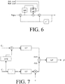
- Such a low-pass filter is shown in FIG. 6 .
- FIG. 6 shows a block diagram illustrating how the low-pass filter given in FIG. 4 may be implemented with different attack and release coefficients.
- the different time constants are applied depending on whether the input is increasing (attack) or decreasing (release).
- attack and release times will however result in a biased estimate.
- FIG. 7 shows an exemplary block diagram illustrating how the adaptation factor ⁇ is calculated from equation (1), but compared to FIG. 3 , we do not only low-pass filter C 2 * C 1 and
- FIG. 7 shows an exemplary block diagram illustrating how the adaptation factor ⁇ is calculated from equation (1), but compared to FIG. 3 , we do not only low-pass filter C 2 * C 1 and
- Another option is to apply an adaptive smoothing coefficient that changes if a sudden input level change is detected. Embodiments of such low-pass filters are shown in FIG. 8A and 8B .
- FIG. 8A shows a first exemplary block diagram of an improved low-pass filter.
- the low-pass filter is able to change its time constant (or the equivalent coefficient (coef)) based on the difference between the input signal (Input) filtered by a low-pass filter (IIR-filter, cf. FIG. 4 ) having a (e.g. fixed) fast time constant and the input signal filtered by a low-pass filter having a (variable) slower time constant. If the difference ⁇ Input between the two low-pass filters is high, it indicates a sudden change of the input level.
- IIR-filter IIR-filter, cf. FIG. 4
- This change of input level will enable a change of the time constant of the low-pass filter with the slow time constant to a faster time constant (the mapping function shown in the function block (fcn) indicating a change from slow to fast adaptation (larger to smaller time constants) with increasing input signal difference ⁇ Input.
- the low-pass filter will be able to adapt faster when we see sudden input level changes happen. If we only see small changes to the input level, a slower time constant is applied.
- By filtering the input signal by low-pass filters having different time constants (cf. LP-filtered Input) we will be able to detect when the level suddenly changes. Based on the level difference, we may adjust the coefficient by a non-linear function ( fcn in FIG. 8A ).
- the non-linear function changes between a slow and a fast time constant, if the absolute difference between the signals are greater than a given threshold.
- the smoothing coefficient changes from a slow time constant to a faster time constant, hereby allowing a fast convergence until the new input level is reached.
- the time constant returns to its slower value.
- the function unit comprises a magnitude unit
- FIG. 8B shows a second exemplary block diagram of an improved low-pass filter.
- the embodiment is similar to the embodiment of FIG. 8A , but the input difference signal is generated on the basis of two filtered signals with fixed fast and slow smoothing coefficients, and the resulting adapted smoothing coefficient (coef) is used to control the smoothing of a separate IIR filter that provides the LP-filtered input.
- coef adapted smoothing coefficient
- the resulting smoothing estimate from the low-pass filter shown in FIG. 8A or 8B is shown in FIG. 9 .
- the time constant is adapted to change from slow adaptation to a faster convergence (compared to the dashed line showing the slower convergence, cf. FIG. 5A ).
- the time constant is changed back to the slower value.
- we obtain faster convergence compared to the dashed line showing the convergence using the slower time constant).
- FIG. 10 shows an exemplary block diagram of an improved low-pass filter with a similar low-pass filter structure as in FIG. 8A , but in FIG. 10 , the adaptive coefficient depends on the level changes of
- the adaptive coefficient depends on the level changes of
- the adaptive time constant is used as coefficient for the slow low-pass filter.
- FIG. 11 shows an exemplary block diagram of an improved low-pass filter with a similar low-pass filter structure as in FIG. 10 , but in the embodiment of FIG. 11 the adaptive coefficient (coef) is estimated from a difference between two low-pass filtered estimates of
- the adaptive coefficient is estimated from a difference between two low-pass filtered estimates of
- a voice activity detector may be used to halt the update (by setting the coefficient to 0). In that case, the adaptive coefficient is solely updated during speech pauses.
- FIG. 12 shows an embodiment of a hearing aid according to the present disclosure comprising a BTE-part located behind an ear or a user and an ITE part located in an ear canal of the user.
- FIG. 12 illustrates an exemplary hearing aid ( HD ) formed as a receiver in the ear (RITE) type hearing aid comprising a BTE-part ( BTE ) adapted for being located behind pinna and a part ( ITE ) comprising an output transducer (e.g. a loudspeaker/receiver, SPK) adapted for being located in an ear canal ( Ear canal ) of the user (e.g. exemplifying a hearing aid (HD) as shown in FIG. 13A, 13B ).
- the BTE-part ( BTE ) and the ITE-part ( ITE ) are connected (e.g. electrically connected) by a connecting element ( IC ).
- IC connecting element
- the BTE part ( BTE ) comprises two input transducers (here microphones) ( M BTE1 , M BTE2 ) each for providing an electric input audio signal representative of an input sound signal ( S BTE ) from the environment.
- the input sound signal S BTE includes a contribution from sound source S , S being e.g. sufficiently far away from the user (and thus from hearing device HD) so that its contribution to the acoustic signal S BTE is in the acoustic far-field.
- the hearing aid of FIG. 12 further comprises two wireless receivers ( WLR 1 , WLR 2 ) for providing respective directly received auxiliary audio and/or information signals.
- the hearing aid ( HD ) further comprises a substrate ( SUB ) whereon a number of electronic components are mounted, functionally partitioned according to the application in question (analogue, digital, passive components, etc.), but including a configurable signal processing unit ( SPU ), a beam former filtering unit ( BFU ), and a memory unit ( MEM ) coupled to each other and to input and output units via electrical conductors Wx .
- the mentioned functional units (as well as other components) may be partitioned in circuits and components according to the application in question (e.g. with a view to size, power consumption, analogue vs. digital processing, etc.), e.g.
- the configurable signal processing unit ( SPU ) provides an enhanced audio signal (cf. signal OUT in FIG. 13A, 13B ), which is intended to be presented to a user.
- the ITE part ( ITE ) comprises an output unit in the form of a loudspeaker (receiver) ( SPK ) for converting the electric signal ( OUT ) to an acoustic signal (providing, or contributing to, acoustic signal S ED at the ear drum ( Ear drum ).
- the ITE-part further comprises an input unit comprising an input transducer (e.g. a microphone) ( M ITE ) for providing an electric input audio signal representative of an input sound signal S ITE from the environment (including from sound source S) at or in the ear canal.
- the hearing aid may comprise only the BTE-microphones ( M BTE1 , M BTE2 ).
- the hearing aid may comprise only the ITE-microphone ( M ITE ).
- the hearing aid may comprise an input unit ( IT 3 ) located elsewhere than at the ear canal in combination with one or more input units located in the BTE-part and/or the ITE-part.
- the ITE-part further comprises a guiding element, e.g. a dome, ( DO ) for guiding and positioning the ITE-part in the ear canal of the user.
- the hearing aid ( HD ) exemplified in FIG. 12 is a portable device and further comprises a battery ( BAT ) for energizing electronic components of the BTE- and ITE-parts.
- the hearing aid ( HD ) comprises a directional microphone system (beam former filtering unit ( BFU )) adapted to enhance a target acoustic source among a multitude of acoustic sources in the local environment of the user wearing the hearing aid device.
- the directional system is adapted to detect (such as adaptively detect) from which direction a particular part of the microphone signal (e.g. a target part and/or a noise part) originates.
- the beam former filtering unit is adapted to receive inputs from a user interface (e.g. a remote control or a smartphone) regarding the present target direction.
- the memory unit ( MEM ) may e.g.
- the hearing aid of FIG. 12 may constitute or form part of a hearing aid and/or a binaural hearing aid system according to the present disclosure.
- the hearing aid (HD) may comprise a user interface UI, e.g. as shown in FIG. 12 implemented in an auxiliary device (AUX), e.g. a remote control, e.g. implemented as an APP in a smartphone or other portable (or stationary) electronic device.
- auxiliary device e.g. a remote control
- the screen of the user interface illustrates a Smooth beamforming APP.
- Parameters that govern or influence the current smoothing of adaptive beamforming here fast and slow smoothing coefficients of low pass filters involved in the determination of the adaptive beamformer parameter ⁇ (cf. discussion in connection with FIG. 8A , 8B , and FIG. 10 , 11 ) can be controlled via the Smooth beamforming APP (with the subtitle: 'Directionality.
- the smoothing parameters 'Fast coefficient' and 'Slow coefficient' can be set via respective sliders to a value between a minimum value (0) and a maximum value (1).
- the currently set values (here 0.8 and 0.2, respectively) are shown on the screen at the location of the slider on the (grey shaded) bar that span the configurable range of values.
- the coefficients could as well be shown as derived parameters such as time constants or other descriptions such as "calm” or "aggressive”.
- the arrows at the bottom of the screen allow changes to a preceding and a proceeding screen of the APP, and a tab on the circular dot between the two arrows brings up a menu that allows the selection of other APPs or features of the device.
- the auxiliary device and the hearing aid are adapted to allow communication of data representative of the currently selected direction (if deviating from a predetermined direction (already stored in the hearing aid)) to the hearing aid via a, e.g. wireless, communication link (cf. dashed arrow WL2 in FIG. 12 ).
- the communication link WL2 may e.g. be based on far field communication, e.g. Bluetooth or Bluetooth Low Energy (or similar technology), implemented by appropriate antenna and transceiver circuitry in the hearing aid (HD) and the auxiliary device (AUX), indicated by transceiver unit WLR 2 in the hearing aid.
- FIG. 13A shows a block diagram of a first embodiment of a hearing aid according to the present disclosure.
- the hearing aid of FIG. 13A may e.g. comprise a 2-microphone beam former configuration as e.g. shown in FIG. 1,2 , and a signal processing unit (SPU) for (further) processing the beamformed signal Y BF and providing a processed signal OUT.
- the signal processing unit may be configured to apply a level and frequency dependent shaping of the beamformed signal, e.g. to compensate for a user's hearing impairment.
- the processed signal (OUT) is fed to an output unit for presentation to a user as a signal perceivable as sound.
- FIG. 1 shows a block diagram of a first embodiment of a hearing aid according to the present disclosure.
- the hearing aid of FIG. 13A may e.g. comprise a 2-microphone beam former configuration as e.g. shown in FIG. 1,2 , and a signal processing unit (SPU) for (further) processing the beam
- the output unit comprises a loudspeaker (SPK) for presenting the processed signal (OUT) to the user as sound.
- SPK loudspeaker
- the forward path from the microphones to the loudspeaker of the hearing aid may be operated in the time domain.
- the hearing aid may further comprise a user interface (UI) and one or more detectors (DET) allowing user inputs and detector inputs (e.g. from a user interface as illustrated in FIG. 12 ) to be received by the beam former filtering unit (BFU).
- BFU beam former filtering unit
- FIG. 13B shows a block diagram of a second embodiment of a hearing aid according to the present disclosure.
- the signal processing unit may be configured to apply a level and frequency dependent shaping of the beamformed signal, e.g. to compensate for a user's hearing impairment (and/or a challenging acoustic environment).
- the processed frequency band signals OU(k) are fed to a synthesis filter bank FBS for converting the frequency band signals OU(k) to a single time-domain processed (output) signal OUT, which is fed to an output unit for presentation to a user as a stimulus perceivable as sound.
- the output unit comprises a loudspeaker (SPK) for presenting the processed signal (OUT) to the user as sound.
- the forward path from the microphones (M BTE1 , M BTE2 ) to the loudspeaker (SPK) of the hearing aid is (mainly) operated in the time-frequency domain (in K frequency sub-bands).
- FIG. 14 shows a flow diagram of a method of operating an adaptive beam former for providing a resulting beamformed signal Y BF of a hearing aid according to an embodiment of the present disclosure.
- the method is configured to operate a hearing aid adapted for being located in an operational position at or in or behind an ear or fully or partially implanted in the head of a user.
- the method comprises
- a method of adaptively smoothing covariance matrices is outlined in the following.
- a particular use of the scheme is for (adaptively) estimating a direction of arrival of sound from a target sound source to a person (e.g. a user of a hearing aid, e.g. a hearing aid according to the present disclosure).
- the method is exemplified as an alternative scheme for smoothing of the adaptation parameter P(k) according to the present disclosure (cf. FIG. 16A-16D and 17A, 17B ).
- X k m S k m + V k m , where k denotes the frequency channel index and m denotes the time frame index.
- X(k,m) [ X 1 (k,m), X 2 (k,m), ..., X M ( k , m )] T .
- the signal at the i th microphone, x i is a linear mixture of the target signal s i and the noise v i .
- v i is the sum of all noise contributions from different directions as well as microphone noise.
- the target signal at the reference microphone s ref is given by the target signal s convolved by the acoustic transfer function h between the target location and the location of the reference microphone.
- the relative transfer function d depends on the location of the target signal. As this is typically the direction of interest, we term d the look vector.
- d the look vector.
- a target power spectral density ⁇ S 2 k m at the reference microphone i.e.
- M x M matrix C s ( k,m ) is a rank 1 matrix, as each column of C s ( k,m ) is proportional to d ( k,m ).
- C s the beneficial part (i.e., the target part) of the speech signal is assumed to be coherent/directional.
- Parts of the speech signal, which are not beneficial, are captured by the second term.
- a look vector estimate can be found efficiently in the case of only two microphones based on estimates of the noisy input covariance matrix and the noise only covariance matrix.
- Each element of our noisy covariance matrix is estimated by low-pass filtering the outer product of the input signal, XX H .
- C no could represent a situation where the target DOA is zero degrees (front direction), such that the system prioritizes the front direction when speech is absent.
- C no may e.g. be selected as an initial value of C x .
- the noise covariance matrix is updated when only noise is present. Whether the target is present or not may be determined by a modulation-based voice activity detector. It should be noted that “Target present” (cf. FIG. 15C ) is not necessarily the same as the inverse of "Noise Only”.
- the VAD indicators controlling the update could be derived from different thresholds on momentary SNR or Modulation Index estimates.
- the normalized covariance ⁇ m C x 11 ⁇ 1 C x 12 , can be observed an indicator for changes in the target DOA (where C x 11 ⁇ 1 and C x 12 are complex numbers).
- log normalized covariance measure ⁇ m ⁇ k log max 0 , Im C ⁇ x 12 + 1 ⁇ log C ⁇ x 11 , Two instances of the (log) normalized covariance measure are calculated, a fast instance ⁇ ( m ) and an instance ⁇ ( m ) with variable update rate.
- ⁇ ⁇ m ⁇ ⁇ 0 , ⁇ ⁇ m ⁇ ⁇ ⁇ m ⁇ ⁇ ⁇ ⁇ , ⁇ ⁇ m ⁇ ⁇ ⁇ m > ⁇
- ⁇ 0 is a slow time constant smoothing factor, i.e. ⁇ 0 ⁇ ⁇
- ⁇ is a constant. Note that the same smoothing factor ⁇ ( m ) is used across frequency bands k.
- FIG. 15A, 15B and 15C illustrate a general embodiment of the variable time constant covariance estimator as outlined above.
- FIG. 15A schematically shows a covariance smoothing unit according to the present disclosure.
- the covariance unit comprises a pre-smoothing unit (PreS) and a variable smoothing unit (VarS).
- variable smoothing unit makes a variable smoothing of the signals X 11 , X 12 and X 22 based on adaptively determined attack and release times in dependence of changes in the acoustic environment as outlined above, and provides smoothed covariance estimators C x 11 ( m ), C x 12 ( m ) and C x 22 ( m ).
- the pre-smoothing unit makes an initial smoothing over time (illustrated by ABS-squared units
- X 1 and X 2 may e.g. represent first (e.g. front) and second (e.g. rear) (typically noisy) microphone signals of a hearing aid.
- Elements C x11 , and C x22 represent variances (e.g. variations in amplitude of the input signals), whereas element C x12 represent co-variances (e.g. representative of changes in phase (and thus direction) (and amplitude)).
- FIG. 15C shows an embodiment of the variable smoothing unit (VarS) providing adaptively smoothed of covariance estimators C x 11 ( m ), C x 12 ( m ), and C x 22 ( m ), as discussed above.
- VarS variable smoothing unit
- the Target Present input is e.g. a control input from a voice activity detector.
- the Target Present input (cf. signal TP in FIG. 15A ) is a binary estimate (e.g. 1 or 0) of the presence of speech in a given time frame or time segment.
- the Target Present input represents a probability of the presence (or absence) of speech in a current input signal (e.g. one of the microphone signals, e.g. X 1 (k,m)). In the latter case, the Target Present input may take on values in the interval between 0 and 1.
- the Target Present input may e.g. be an output from a voice activity detector (cf. VAD in FIG. 15C ), e.g. as known in the art.
- the Fast Rel Coef , the Fast Atk Coref , the Slow Rel Coef , and the Slow Atk Coef are fixed (e.g. determined in advance of the use of the procedure) fast and slow attack and release times, respectively. Generally, fast attack and release times are shorter than slow attack and release times.
- the time constants (cf. signals TC in FIG. 15A ) are stored in a memory of the hearing aid (cf. e.g. MEM in FIG. 15A ). In an embodiment the time constants may be updated during use of the hearing aid.
- the exemplary implementation in FIG. 15C is chosen for its computational simplicity (which is of importance in a hearing device having a limited power budget), as provided by the conversion to a logarithmic domain.
- the adaptive low-pass filters used in FIG. 15C can e.g. be implemented as shown in FIG. 4 , where coef is the smoothing factor ⁇ ( m ) (or ⁇ ( m )).
- FIG. 16A, 16B and 16C illustrate a particular embodiment of the variable time constant covariance estimator as outlined above.
- the difference of the embodiment of FIG. 16A, 16B and 16C to the general embodiment of FIG. 15A, 15B, 15C is that the inputs are beamformed signals formed by beam patterns C1 and C2 (instead of microphone signals x directly).
- FIG. 16D schematically illustrates the determination of ⁇ based on smoothed covariance matrices ( ⁇
- the above scheme may e.g. be relevant for adaptively estimating a direction of arrival of alternatingly active sound sources at different locations (e.g. at different angles in a horizontal plane relative to a user wearing one or more hearing aids according to the present disclosure).
- FIG. 17A corresponds to FIG. 3 and FIG. 17B corresponds to FIG. 7 , but in FIG. 17A and 17B , the variable time constant covariance estimator according to the present disclosure (and as depicted in FIG. 16A-16C ) is used for adaptively smoothing ⁇ .
- FIG. 18 comprises a pre-smoothing unit (PreS), a variable smoothing unit (VarS) and a ⁇ calculation unit (beta) as also illustrated in FIG. 17A and 17B , but in an alternative embodiment.
- PreS pre-smoothing unit
- VarS variable smoothing unit
- ⁇ calculation unit beta
- the LP blocks may be time varying (e.g. adaptive) as e.g. shown in connection with FIG. 15C and FIG. 16C .
- two matrix multiplication blocks NUMC, and DENC, respectively
- NUMC numerator
- den denominator
- connection or “coupled” as used herein may include wirelessly connected or coupled.
- the term “and/or” includes any and all combinations of one or more of the associated listed items. The steps of any disclosed method is not limited to the exact order stated herein, unless expressly stated otherwise.
Landscapes
- Engineering & Computer Science (AREA)
- Acoustics & Sound (AREA)
- Signal Processing (AREA)
- Physics & Mathematics (AREA)
- Health & Medical Sciences (AREA)
- General Health & Medical Sciences (AREA)
- Otolaryngology (AREA)
- Neurosurgery (AREA)
- Computer Networks & Wireless Communication (AREA)
- Computational Linguistics (AREA)
- Quality & Reliability (AREA)
- Audiology, Speech & Language Pathology (AREA)
- Human Computer Interaction (AREA)
- Multimedia (AREA)
- Circuit For Audible Band Transducer (AREA)
- Telephone Function (AREA)
Priority Applications (2)
| Application Number | Priority Date | Filing Date | Title |
|---|---|---|---|
| EP19151896.8A EP3509325B1 (de) | 2016-05-30 | 2017-05-30 | Hörgerät mit strahlformerfiltereinheit mit einer glättungseinheit |
| DK19151896.8T DK3509325T3 (da) | 2016-05-30 | 2017-05-30 | Høreapparat, der omfatter en stråleformerfiltreringsenhed, der omfatter en udglatningsenhed |
Applications Claiming Priority (1)
| Application Number | Priority Date | Filing Date | Title |
|---|---|---|---|
| EP16172042 | 2016-05-30 |
Related Child Applications (3)
| Application Number | Title | Priority Date | Filing Date |
|---|---|---|---|
| EP19151896.8A Division EP3509325B1 (de) | 2016-05-30 | 2017-05-30 | Hörgerät mit strahlformerfiltereinheit mit einer glättungseinheit |
| EP19151896.8A Previously-Filed-Application EP3509325B1 (de) | 2016-05-30 | 2017-05-30 | Hörgerät mit strahlformerfiltereinheit mit einer glättungseinheit |
| EP19151896.8A Division-Into EP3509325B1 (de) | 2016-05-30 | 2017-05-30 | Hörgerät mit strahlformerfiltereinheit mit einer glättungseinheit |
Publications (2)
| Publication Number | Publication Date |
|---|---|
| EP3253075A1 true EP3253075A1 (de) | 2017-12-06 |
| EP3253075B1 EP3253075B1 (de) | 2019-03-20 |
Family
ID=56092822
Family Applications (2)
| Application Number | Title | Priority Date | Filing Date |
|---|---|---|---|
| EP17173422.1A Active EP3253075B1 (de) | 2016-05-30 | 2017-05-30 | Hörgerät mit strahlformerfiltrierungseinheit mit einer glättungseinheit |
| EP19151896.8A Active EP3509325B1 (de) | 2016-05-30 | 2017-05-30 | Hörgerät mit strahlformerfiltereinheit mit einer glättungseinheit |
Family Applications After (1)
| Application Number | Title | Priority Date | Filing Date |
|---|---|---|---|
| EP19151896.8A Active EP3509325B1 (de) | 2016-05-30 | 2017-05-30 | Hörgerät mit strahlformerfiltereinheit mit einer glättungseinheit |
Country Status (4)
| Country | Link |
|---|---|
| US (2) | US10231062B2 (de) |
| EP (2) | EP3253075B1 (de) |
| CN (2) | CN107454538B (de) |
| DK (2) | DK3253075T3 (de) |
Cited By (8)
| Publication number | Priority date | Publication date | Assignee | Title |
|---|---|---|---|---|
| EP3413589A1 (de) | 2017-06-09 | 2018-12-12 | Oticon A/s | Mikrofonsystem und hörgerät mit einem mikrofonsystem |
| EP3525488A1 (de) | 2018-02-09 | 2019-08-14 | Oticon A/s | Hörgerät mit einer strahlformerfiltrierungseinheit zur verringerung der rückkopplung |
| CN110636429A (zh) * | 2018-06-22 | 2019-12-31 | 奥迪康有限公司 | 包括声学事件检测器的听力装置 |
| EP3902285A1 (de) | 2020-04-22 | 2021-10-27 | Oticon A/s | Tragbare vorrichtung mit einem richtsystem |
| EP4007308A1 (de) | 2020-11-27 | 2022-06-01 | Oticon A/s | Hörgerätesystem mit einer datenbank von akustischen übertragungsfunktionen |
| EP4250765A1 (de) | 2022-03-25 | 2023-09-27 | Oticon A/s | Hörsystem mit einem hörgerät und einer externen verarbeitungsvorrichtung |
| EP4287646A1 (de) | 2022-05-31 | 2023-12-06 | Oticon A/s | Hörgerät oder hörgerätesystem mit schallquellenortungsschätzer |
| EP4398605A1 (de) | 2023-01-06 | 2024-07-10 | Oticon A/s | Hörgerät und verfahren |
Families Citing this family (25)
| Publication number | Priority date | Publication date | Assignee | Title |
|---|---|---|---|---|
| US9554207B2 (en) | 2015-04-30 | 2017-01-24 | Shure Acquisition Holdings, Inc. | Offset cartridge microphones |
| US9565493B2 (en) | 2015-04-30 | 2017-02-07 | Shure Acquisition Holdings, Inc. | Array microphone system and method of assembling the same |
| US10367948B2 (en) | 2017-01-13 | 2019-07-30 | Shure Acquisition Holdings, Inc. | Post-mixing acoustic echo cancellation systems and methods |
| US11423924B2 (en) * | 2018-02-23 | 2022-08-23 | Nippon Telegraph And Telephone Corporation | Signal analysis device for modeling spatial characteristics of source signals, signal analysis method, and recording medium |
| EP3804356A1 (de) | 2018-06-01 | 2021-04-14 | Shure Acquisition Holdings, Inc. | Musterbildende mikrofonanordnung |
| US11297423B2 (en) | 2018-06-15 | 2022-04-05 | Shure Acquisition Holdings, Inc. | Endfire linear array microphone |
| EP3837861B1 (de) * | 2018-08-15 | 2023-10-04 | Widex A/S | Verfahren zum betrieb eines hörgerätesystems und ein hörgerätesystem |
| WO2020061353A1 (en) | 2018-09-20 | 2020-03-26 | Shure Acquisition Holdings, Inc. | Adjustable lobe shape for array microphones |
| EP3629602A1 (de) * | 2018-09-27 | 2020-04-01 | Oticon A/s | Hörvorrichtung und ein hörsystem mit einer vielzahl von adaptiven zweikanaligen beamformern |
| TW202044236A (zh) | 2019-03-21 | 2020-12-01 | 美商舒爾獲得控股公司 | 具有抑制功能的波束形成麥克風瓣之自動對焦、區域內自動對焦、及自動配置 |
| US11558693B2 (en) | 2019-03-21 | 2023-01-17 | Shure Acquisition Holdings, Inc. | Auto focus, auto focus within regions, and auto placement of beamformed microphone lobes with inhibition and voice activity detection functionality |
| EP3942842A1 (de) | 2019-03-21 | 2022-01-26 | Shure Acquisition Holdings, Inc. | Gehäuse und zugehörige konstruktionsmerkmale für mikrofone einer deckenanordnung |
| EP3973716A1 (de) | 2019-05-23 | 2022-03-30 | Shure Acquisition Holdings, Inc. | Steuerbare lautsprecheranordnung, system und verfahren dafür |
| JP2022535229A (ja) | 2019-05-31 | 2022-08-05 | シュアー アクイジッション ホールディングス インコーポレイテッド | 音声およびノイズアクティビティ検出と統合された低レイテンシオートミキサー |
| EP3764660B1 (de) * | 2019-07-10 | 2023-08-30 | Analog Devices International Unlimited Company | Signalverarbeitungsverfahren und systeme für adaptive strahlenformung |
| EP3764359B1 (de) | 2019-07-10 | 2024-08-28 | Analog Devices International Unlimited Company | Signalverarbeitungsverfahren und systeme für mehrfokusstrahlformung |
| EP3764358B1 (de) | 2019-07-10 | 2024-05-22 | Analog Devices International Unlimited Company | Signalverarbeitungsverfahren und -systeme zur strahlformung mit windblasschutz |
| CN114467312A (zh) | 2019-08-23 | 2022-05-10 | 舒尔获得控股公司 | 具有改进方向性的二维麦克风阵列 |
| US12028678B2 (en) | 2019-11-01 | 2024-07-02 | Shure Acquisition Holdings, Inc. | Proximity microphone |
| US11552611B2 (en) | 2020-02-07 | 2023-01-10 | Shure Acquisition Holdings, Inc. | System and method for automatic adjustment of reference gain |
| WO2021243368A2 (en) | 2020-05-29 | 2021-12-02 | Shure Acquisition Holdings, Inc. | Transducer steering and configuration systems and methods using a local positioning system |
| EP4040806A3 (de) * | 2021-01-18 | 2022-12-21 | Oticon A/s | Hörgerät mit einem geräuschreduzierungssystem |
| US11330378B1 (en) | 2021-01-20 | 2022-05-10 | Oticon A/S | Hearing device comprising a recurrent neural network and a method of processing an audio signal |
| WO2022165007A1 (en) | 2021-01-28 | 2022-08-04 | Shure Acquisition Holdings, Inc. | Hybrid audio beamforming system |
| EP4156711A1 (de) * | 2021-09-28 | 2023-03-29 | GN Audio A/S | Audiovorrichtung mit doppelter strahlformung |
Citations (4)
| Publication number | Priority date | Publication date | Assignee | Title |
|---|---|---|---|---|
| US5473701A (en) * | 1993-11-05 | 1995-12-05 | At&T Corp. | Adaptive microphone array |
| EP2296142A2 (de) * | 2005-08-02 | 2011-03-16 | Dolby Laboratories Licensing Corporation | Steuerung von räumlichen Audiocodierungsparametern als Funktion von Gehörereignissen |
| US20150221313A1 (en) * | 2012-09-21 | 2015-08-06 | Dolby International Ab | Coding of a sound field signal |
| US9301049B2 (en) * | 2002-02-05 | 2016-03-29 | Mh Acoustics Llc | Noise-reducing directional microphone array |
Family Cites Families (16)
| Publication number | Priority date | Publication date | Assignee | Title |
|---|---|---|---|---|
| US5651071A (en) * | 1993-09-17 | 1997-07-22 | Audiologic, Inc. | Noise reduction system for binaural hearing aid |
| WO2001097558A2 (en) * | 2000-06-13 | 2001-12-20 | Gn Resound Corporation | Fixed polar-pattern-based adaptive directionality systems |
| US7171008B2 (en) * | 2002-02-05 | 2007-01-30 | Mh Acoustics, Llc | Reducing noise in audio systems |
| US7970123B2 (en) * | 2005-10-20 | 2011-06-28 | Mitel Networks Corporation | Adaptive coupling equalization in beamforming-based communication systems |
| ATE491314T1 (de) * | 2006-04-05 | 2010-12-15 | Harman Becker Automotive Sys | Verfahren zum automatischen entzerren eines beschallungssystems |
| SG177623A1 (en) * | 2009-07-15 | 2012-02-28 | Widex As | Method and processing unit for adaptive wind noise suppression in a hearing aid system and a hearing aid system |
| BR112012031656A2 (pt) * | 2010-08-25 | 2016-11-08 | Asahi Chemical Ind | dispositivo, e método de separação de fontes sonoras, e, programa |
| CN102809742B (zh) * | 2011-06-01 | 2015-03-18 | 杜比实验室特许公司 | 声源定位设备和方法 |
| CN102499712B (zh) * | 2011-09-30 | 2014-07-23 | 重庆大学 | 一种基于特征空间的前后向自适应波束形成方法 |
| CN102970638B (zh) * | 2011-11-25 | 2016-01-27 | 斯凯普公司 | 处理信号 |
| US9173025B2 (en) * | 2012-02-08 | 2015-10-27 | Dolby Laboratories Licensing Corporation | Combined suppression of noise, echo, and out-of-location signals |
| EP3462452A1 (de) * | 2012-08-24 | 2019-04-03 | Oticon A/s | Geräuschschätzung zur verwendung mit geräuschreduzierung und echounterdrückung in persönlicher kommunikation |
| DK3057340T3 (da) * | 2015-02-13 | 2019-08-19 | Oticon As | Partnermikrofonenhed og et høresystem, der omfatter en partnermikrofonenhed |
| CN105044706B (zh) * | 2015-06-18 | 2018-06-29 | 中国科学院声学研究所 | 一种自适应波束形成方法 |
| US9980055B2 (en) * | 2015-10-12 | 2018-05-22 | Oticon A/S | Hearing device and a hearing system configured to localize a sound source |
| EP3236672B1 (de) * | 2016-04-08 | 2019-08-07 | Oticon A/s | Hörgerät mit einer strahlformerfiltrierungseinheit |
-
2017
- 2017-05-30 EP EP17173422.1A patent/EP3253075B1/de active Active
- 2017-05-30 US US15/608,294 patent/US10231062B2/en active Active
- 2017-05-30 EP EP19151896.8A patent/EP3509325B1/de active Active
- 2017-05-30 DK DK17173422.1T patent/DK3253075T3/en active
- 2017-05-30 DK DK19151896.8T patent/DK3509325T3/da active
- 2017-05-31 CN CN201710400520.5A patent/CN107454538B/zh active Active
- 2017-05-31 CN CN202110619673.5A patent/CN113453134B/zh active Active
-
2019
- 2019-01-24 US US16/256,742 patent/US11109163B2/en active Active
Patent Citations (4)
| Publication number | Priority date | Publication date | Assignee | Title |
|---|---|---|---|---|
| US5473701A (en) * | 1993-11-05 | 1995-12-05 | At&T Corp. | Adaptive microphone array |
| US9301049B2 (en) * | 2002-02-05 | 2016-03-29 | Mh Acoustics Llc | Noise-reducing directional microphone array |
| EP2296142A2 (de) * | 2005-08-02 | 2011-03-16 | Dolby Laboratories Licensing Corporation | Steuerung von räumlichen Audiocodierungsparametern als Funktion von Gehörereignissen |
| US20150221313A1 (en) * | 2012-09-21 | 2015-08-06 | Dolby International Ab | Coding of a sound field signal |
Non-Patent Citations (3)
| Title |
|---|
| "Acoustic Array Systems", 29 January 2013, JOHN WILEY & SONS SINGAPORE PTE. LTD., Singapore, ISBN: 978-0-470-82723-9, article MINGSIAN R. BAI ET AL: "Frequency-Domain Array Beamformers for Noise Reduction", pages: 315 - 344, XP055323735, DOI: 10.1002/9780470827253.ch8 * |
| ELKO G W ED - STYLIANOU YANNIS MOWLAEE PEJMAN SAEIDI RAHIM: "Microphone array systems for hands-free telecommunication", SPEECH COMMUNICATION, ELSEVIER SCIENCE PUBLISHERS, AMSTERDAM, NL, vol. 20, no. 3, 1 December 1996 (1996-12-01), pages 229 - 240, XP004016547, ISSN: 0167-6393, DOI: 10.1016/S0167-6393(96)00057-X * |
| LOCKWOOD MICHAEL E ET AL: "Performance of time- and frequency-domain binaural beamformers based on recorded signals from real rooms", THE JOURNAL OF THE ACOUSTICAL SOCIETY OF AMERICA, AMERICAN INSTITUTE OF PHYSICS FOR THE ACOUSTICAL SOCIETY OF AMERICA, NEW YORK, NY, US, vol. 115, no. 1, 1 January 2004 (2004-01-01), pages 379 - 391, XP012072089, ISSN: 0001-4966, DOI: 10.1121/1.1624064 * |
Cited By (21)
| Publication number | Priority date | Publication date | Assignee | Title |
|---|---|---|---|---|
| EP3413589A1 (de) | 2017-06-09 | 2018-12-12 | Oticon A/s | Mikrofonsystem und hörgerät mit einem mikrofonsystem |
| US10631102B2 (en) | 2017-06-09 | 2020-04-21 | Oticon A/S | Microphone system and a hearing device comprising a microphone system |
| EP3787316A1 (de) | 2018-02-09 | 2021-03-03 | Oticon A/s | Hörgerät mit einer strahlformerfiltrierungseinheit zur verringerung der rückkopplung |
| EP3525488A1 (de) | 2018-02-09 | 2019-08-14 | Oticon A/s | Hörgerät mit einer strahlformerfiltrierungseinheit zur verringerung der rückkopplung |
| CN110139200A (zh) * | 2018-02-09 | 2019-08-16 | 奥迪康有限公司 | 包括用于降低反馈的波束形成器滤波单元的听力装置 |
| US11363389B2 (en) | 2018-02-09 | 2022-06-14 | Oticon A/S | Hearing device comprising a beamformer filtering unit for reducing feedback |
| CN110139200B (zh) * | 2018-02-09 | 2022-05-31 | 奥迪康有限公司 | 包括用于降低反馈的波束形成器滤波单元的听力装置 |
| US10932066B2 (en) | 2018-02-09 | 2021-02-23 | Oticon A/S | Hearing device comprising a beamformer filtering unit for reducing feedback |
| CN110636429B (zh) * | 2018-06-22 | 2022-10-21 | 奥迪康有限公司 | 包括声学事件检测器的听力装置 |
| US10856087B2 (en) | 2018-06-22 | 2020-12-01 | Oticon A/S | Hearing device comprising an acoustic event detector |
| EP4009667A1 (de) * | 2018-06-22 | 2022-06-08 | Oticon A/s | Hörgerät mit einem akustischen ereignisdetektor |
| EP3588981A1 (de) * | 2018-06-22 | 2020-01-01 | Oticon A/s | Hörgerät mit einem akustischen ereignisdetektor |
| CN110636429A (zh) * | 2018-06-22 | 2019-12-31 | 奥迪康有限公司 | 包括声学事件检测器的听力装置 |
| EP3902285A1 (de) | 2020-04-22 | 2021-10-27 | Oticon A/s | Tragbare vorrichtung mit einem richtsystem |
| US11330366B2 (en) | 2020-04-22 | 2022-05-10 | Oticon A/S | Portable device comprising a directional system |
| EP4007308A1 (de) | 2020-11-27 | 2022-06-01 | Oticon A/s | Hörgerätesystem mit einer datenbank von akustischen übertragungsfunktionen |
| US11991499B2 (en) | 2020-11-27 | 2024-05-21 | Oticon A/S | Hearing aid system comprising a database of acoustic transfer functions |
| EP4250765A1 (de) | 2022-03-25 | 2023-09-27 | Oticon A/s | Hörsystem mit einem hörgerät und einer externen verarbeitungsvorrichtung |
| EP4287646A1 (de) | 2022-05-31 | 2023-12-06 | Oticon A/s | Hörgerät oder hörgerätesystem mit schallquellenortungsschätzer |
| EP4398605A1 (de) | 2023-01-06 | 2024-07-10 | Oticon A/s | Hörgerät und verfahren |
| EP4398604A1 (de) | 2023-01-06 | 2024-07-10 | Oticon A/s | Hörgerät und verfahren |
Also Published As
| Publication number | Publication date |
|---|---|
| CN107454538B (zh) | 2021-06-25 |
| CN113453134A (zh) | 2021-09-28 |
| DK3253075T3 (en) | 2019-06-11 |
| US20170347206A1 (en) | 2017-11-30 |
| US11109163B2 (en) | 2021-08-31 |
| DK3509325T3 (da) | 2021-03-22 |
| EP3509325A2 (de) | 2019-07-10 |
| CN107454538A (zh) | 2017-12-08 |
| EP3509325B1 (de) | 2021-01-27 |
| US10231062B2 (en) | 2019-03-12 |
| EP3509325A3 (de) | 2019-11-06 |
| EP3253075B1 (de) | 2019-03-20 |
| CN113453134B (zh) | 2023-06-06 |
| US20190158965A1 (en) | 2019-05-23 |
Similar Documents
| Publication | Publication Date | Title |
|---|---|---|
| US11109163B2 (en) | Hearing aid comprising a beam former filtering unit comprising a smoothing unit | |
| US10269368B2 (en) | Audio processing device and a method for estimating a signal-to-noise-ratio of a sound signal | |
| EP3514792B1 (de) | Verfahren zur optimierung eines algorithmus zur sprachverbesserung mit einem algorithmus zur vorhersage der sprachverständlichkeit | |
| EP2916321B1 (de) | Verarbeitung eines verrauschten audiosignals zur schätzung der ziel- und rauschspektrumsvarianzen | |
| US10580437B2 (en) | Voice activity detection unit and a hearing device comprising a voice activity detection unit | |
| US10861478B2 (en) | Audio processing device and a method for estimating a signal-to-noise-ratio of a sound signal | |
| EP3236672B1 (de) | Hörgerät mit einer strahlformerfiltrierungseinheit | |
| US10701494B2 (en) | Hearing device comprising a speech intelligibility estimator for influencing a processing algorithm | |
| CN110035367B (zh) | 反馈检测器及包括反馈检测器的听力装置 | |
| US10154353B2 (en) | Monaural speech intelligibility predictor unit, a hearing aid and a binaural hearing system | |
| US10433076B2 (en) | Audio processing device and a method for estimating a signal-to-noise-ratio of a sound signal | |
| US11483663B2 (en) | Audio processing device and a method for estimating a signal-to-noise-ratio of a sound signal | |
| EP2916320A1 (de) | Multi-Mikrofonverfahren zur Schätzung von Ziel- und Rauschspektralvarianzen | |
| EP4199541A1 (de) | Hörgerät mit strahlformer mit niedriger komplexität |
Legal Events
| Date | Code | Title | Description |
|---|---|---|---|
| PUAI | Public reference made under article 153(3) epc to a published international application that has entered the european phase |
Free format text: ORIGINAL CODE: 0009012 |
|
| STAA | Information on the status of an ep patent application or granted ep patent |
Free format text: STATUS: THE APPLICATION HAS BEEN PUBLISHED |
|
| AK | Designated contracting states |
Kind code of ref document: A1 Designated state(s): AL AT BE BG CH CY CZ DE DK EE ES FI FR GB GR HR HU IE IS IT LI LT LU LV MC MK MT NL NO PL PT RO RS SE SI SK SM TR |
|
| AX | Request for extension of the european patent |
Extension state: BA ME |
|
| STAA | Information on the status of an ep patent application or granted ep patent |
Free format text: STATUS: REQUEST FOR EXAMINATION WAS MADE |
|
| 17P | Request for examination filed |
Effective date: 20180606 |
|
| RBV | Designated contracting states (corrected) |
Designated state(s): AL AT BE BG CH CY CZ DE DK EE ES FI FR GB GR HR HU IE IS IT LI LT LU LV MC MK MT NL NO PL PT RO RS SE SI SK SM TR |
|
| GRAP | Despatch of communication of intention to grant a patent |
Free format text: ORIGINAL CODE: EPIDOSNIGR1 |
|
| STAA | Information on the status of an ep patent application or granted ep patent |
Free format text: STATUS: GRANT OF PATENT IS INTENDED |
|
| INTG | Intention to grant announced |
Effective date: 20181011 |
|
| GRAS | Grant fee paid |
Free format text: ORIGINAL CODE: EPIDOSNIGR3 |
|
| GRAA | (expected) grant |
Free format text: ORIGINAL CODE: 0009210 |
|
| STAA | Information on the status of an ep patent application or granted ep patent |
Free format text: STATUS: THE PATENT HAS BEEN GRANTED |
|
| AK | Designated contracting states |
Kind code of ref document: B1 Designated state(s): AL AT BE BG CH CY CZ DE DK EE ES FI FR GB GR HR HU IE IS IT LI LT LU LV MC MK MT NL NO PL PT RO RS SE SI SK SM TR |
|
| REG | Reference to a national code |
Ref country code: GB Ref legal event code: FG4D |
|
| REG | Reference to a national code |
Ref country code: CH Ref legal event code: EP |
|
| REG | Reference to a national code |
Ref country code: DE Ref legal event code: R096 Ref document number: 602017002781 Country of ref document: DE |
|
| REG | Reference to a national code |
Ref country code: AT Ref legal event code: REF Ref document number: 1111744 Country of ref document: AT Kind code of ref document: T Effective date: 20190415 |
|
| REG | Reference to a national code |
Ref country code: IE Ref legal event code: FG4D |
|
| REG | Reference to a national code |
Ref country code: DK Ref legal event code: T3 Effective date: 20190607 |
|
| REG | Reference to a national code |
Ref country code: NL Ref legal event code: MP Effective date: 20190320 |
|
| PG25 | Lapsed in a contracting state [announced via postgrant information from national office to epo] |
Ref country code: LT Free format text: LAPSE BECAUSE OF FAILURE TO SUBMIT A TRANSLATION OF THE DESCRIPTION OR TO PAY THE FEE WITHIN THE PRESCRIBED TIME-LIMIT Effective date: 20190320 Ref country code: FI Free format text: LAPSE BECAUSE OF FAILURE TO SUBMIT A TRANSLATION OF THE DESCRIPTION OR TO PAY THE FEE WITHIN THE PRESCRIBED TIME-LIMIT Effective date: 20190320 Ref country code: SE Free format text: LAPSE BECAUSE OF FAILURE TO SUBMIT A TRANSLATION OF THE DESCRIPTION OR TO PAY THE FEE WITHIN THE PRESCRIBED TIME-LIMIT Effective date: 20190320 Ref country code: NO Free format text: LAPSE BECAUSE OF FAILURE TO SUBMIT A TRANSLATION OF THE DESCRIPTION OR TO PAY THE FEE WITHIN THE PRESCRIBED TIME-LIMIT Effective date: 20190620 |
|
| REG | Reference to a national code |
Ref country code: LT Ref legal event code: MG4D |
|
| PG25 | Lapsed in a contracting state [announced via postgrant information from national office to epo] |
Ref country code: BG Free format text: LAPSE BECAUSE OF FAILURE TO SUBMIT A TRANSLATION OF THE DESCRIPTION OR TO PAY THE FEE WITHIN THE PRESCRIBED TIME-LIMIT Effective date: 20190620 Ref country code: RS Free format text: LAPSE BECAUSE OF FAILURE TO SUBMIT A TRANSLATION OF THE DESCRIPTION OR TO PAY THE FEE WITHIN THE PRESCRIBED TIME-LIMIT Effective date: 20190320 Ref country code: LV Free format text: LAPSE BECAUSE OF FAILURE TO SUBMIT A TRANSLATION OF THE DESCRIPTION OR TO PAY THE FEE WITHIN THE PRESCRIBED TIME-LIMIT Effective date: 20190320 Ref country code: HR Free format text: LAPSE BECAUSE OF FAILURE TO SUBMIT A TRANSLATION OF THE DESCRIPTION OR TO PAY THE FEE WITHIN THE PRESCRIBED TIME-LIMIT Effective date: 20190320 Ref country code: GR Free format text: LAPSE BECAUSE OF FAILURE TO SUBMIT A TRANSLATION OF THE DESCRIPTION OR TO PAY THE FEE WITHIN THE PRESCRIBED TIME-LIMIT Effective date: 20190621 Ref country code: NL Free format text: LAPSE BECAUSE OF FAILURE TO SUBMIT A TRANSLATION OF THE DESCRIPTION OR TO PAY THE FEE WITHIN THE PRESCRIBED TIME-LIMIT Effective date: 20190320 |
|
| REG | Reference to a national code |
Ref country code: AT Ref legal event code: MK05 Ref document number: 1111744 Country of ref document: AT Kind code of ref document: T Effective date: 20190320 |
|
| PG25 | Lapsed in a contracting state [announced via postgrant information from national office to epo] |
Ref country code: SK Free format text: LAPSE BECAUSE OF FAILURE TO SUBMIT A TRANSLATION OF THE DESCRIPTION OR TO PAY THE FEE WITHIN THE PRESCRIBED TIME-LIMIT Effective date: 20190320 Ref country code: IT Free format text: LAPSE BECAUSE OF FAILURE TO SUBMIT A TRANSLATION OF THE DESCRIPTION OR TO PAY THE FEE WITHIN THE PRESCRIBED TIME-LIMIT Effective date: 20190320 Ref country code: EE Free format text: LAPSE BECAUSE OF FAILURE TO SUBMIT A TRANSLATION OF THE DESCRIPTION OR TO PAY THE FEE WITHIN THE PRESCRIBED TIME-LIMIT Effective date: 20190320 Ref country code: RO Free format text: LAPSE BECAUSE OF FAILURE TO SUBMIT A TRANSLATION OF THE DESCRIPTION OR TO PAY THE FEE WITHIN THE PRESCRIBED TIME-LIMIT Effective date: 20190320 Ref country code: CZ Free format text: LAPSE BECAUSE OF FAILURE TO SUBMIT A TRANSLATION OF THE DESCRIPTION OR TO PAY THE FEE WITHIN THE PRESCRIBED TIME-LIMIT Effective date: 20190320 Ref country code: ES Free format text: LAPSE BECAUSE OF FAILURE TO SUBMIT A TRANSLATION OF THE DESCRIPTION OR TO PAY THE FEE WITHIN THE PRESCRIBED TIME-LIMIT Effective date: 20190320 Ref country code: PT Free format text: LAPSE BECAUSE OF FAILURE TO SUBMIT A TRANSLATION OF THE DESCRIPTION OR TO PAY THE FEE WITHIN THE PRESCRIBED TIME-LIMIT Effective date: 20190720 Ref country code: AL Free format text: LAPSE BECAUSE OF FAILURE TO SUBMIT A TRANSLATION OF THE DESCRIPTION OR TO PAY THE FEE WITHIN THE PRESCRIBED TIME-LIMIT Effective date: 20190320 |
|
| PG25 | Lapsed in a contracting state [announced via postgrant information from national office to epo] |
Ref country code: SM Free format text: LAPSE BECAUSE OF FAILURE TO SUBMIT A TRANSLATION OF THE DESCRIPTION OR TO PAY THE FEE WITHIN THE PRESCRIBED TIME-LIMIT Effective date: 20190320 Ref country code: PL Free format text: LAPSE BECAUSE OF FAILURE TO SUBMIT A TRANSLATION OF THE DESCRIPTION OR TO PAY THE FEE WITHIN THE PRESCRIBED TIME-LIMIT Effective date: 20190320 |
|
| PG25 | Lapsed in a contracting state [announced via postgrant information from national office to epo] |
Ref country code: AT Free format text: LAPSE BECAUSE OF FAILURE TO SUBMIT A TRANSLATION OF THE DESCRIPTION OR TO PAY THE FEE WITHIN THE PRESCRIBED TIME-LIMIT Effective date: 20190320 Ref country code: IS Free format text: LAPSE BECAUSE OF FAILURE TO SUBMIT A TRANSLATION OF THE DESCRIPTION OR TO PAY THE FEE WITHIN THE PRESCRIBED TIME-LIMIT Effective date: 20190720 |
|
| REG | Reference to a national code |
Ref country code: DE Ref legal event code: R097 Ref document number: 602017002781 Country of ref document: DE |
|
| PLBE | No opposition filed within time limit |
Free format text: ORIGINAL CODE: 0009261 |
|
| STAA | Information on the status of an ep patent application or granted ep patent |
Free format text: STATUS: NO OPPOSITION FILED WITHIN TIME LIMIT |
|
| PG25 | Lapsed in a contracting state [announced via postgrant information from national office to epo] |
Ref country code: MC Free format text: LAPSE BECAUSE OF FAILURE TO SUBMIT A TRANSLATION OF THE DESCRIPTION OR TO PAY THE FEE WITHIN THE PRESCRIBED TIME-LIMIT Effective date: 20190320 |
|
| REG | Reference to a national code |
Ref country code: BE Ref legal event code: MM Effective date: 20190531 |
|
| 26N | No opposition filed |
Effective date: 20200102 |
|
| PG25 | Lapsed in a contracting state [announced via postgrant information from national office to epo] |
Ref country code: LU Free format text: LAPSE BECAUSE OF NON-PAYMENT OF DUE FEES Effective date: 20190530 Ref country code: SI Free format text: LAPSE BECAUSE OF FAILURE TO SUBMIT A TRANSLATION OF THE DESCRIPTION OR TO PAY THE FEE WITHIN THE PRESCRIBED TIME-LIMIT Effective date: 20190320 |
|
| PG25 | Lapsed in a contracting state [announced via postgrant information from national office to epo] |
Ref country code: TR Free format text: LAPSE BECAUSE OF FAILURE TO SUBMIT A TRANSLATION OF THE DESCRIPTION OR TO PAY THE FEE WITHIN THE PRESCRIBED TIME-LIMIT Effective date: 20190320 |
|
| PG25 | Lapsed in a contracting state [announced via postgrant information from national office to epo] |
Ref country code: IE Free format text: LAPSE BECAUSE OF NON-PAYMENT OF DUE FEES Effective date: 20190530 |
|
| PG25 | Lapsed in a contracting state [announced via postgrant information from national office to epo] |
Ref country code: BE Free format text: LAPSE BECAUSE OF NON-PAYMENT OF DUE FEES Effective date: 20190531 |
|
| PG25 | Lapsed in a contracting state [announced via postgrant information from national office to epo] |
Ref country code: CY Free format text: LAPSE BECAUSE OF FAILURE TO SUBMIT A TRANSLATION OF THE DESCRIPTION OR TO PAY THE FEE WITHIN THE PRESCRIBED TIME-LIMIT Effective date: 20190320 |
|
| PG25 | Lapsed in a contracting state [announced via postgrant information from national office to epo] |
Ref country code: MT Free format text: LAPSE BECAUSE OF FAILURE TO SUBMIT A TRANSLATION OF THE DESCRIPTION OR TO PAY THE FEE WITHIN THE PRESCRIBED TIME-LIMIT Effective date: 20190320 Ref country code: HU Free format text: LAPSE BECAUSE OF FAILURE TO SUBMIT A TRANSLATION OF THE DESCRIPTION OR TO PAY THE FEE WITHIN THE PRESCRIBED TIME-LIMIT; INVALID AB INITIO Effective date: 20170530 |
|
| PG25 | Lapsed in a contracting state [announced via postgrant information from national office to epo] |
Ref country code: MK Free format text: LAPSE BECAUSE OF FAILURE TO SUBMIT A TRANSLATION OF THE DESCRIPTION OR TO PAY THE FEE WITHIN THE PRESCRIBED TIME-LIMIT Effective date: 20190320 |
|
| PGFP | Annual fee paid to national office [announced via postgrant information from national office to epo] |
Ref country code: GB Payment date: 20240423 Year of fee payment: 8 |
|
| PGFP | Annual fee paid to national office [announced via postgrant information from national office to epo] |
Ref country code: DE Payment date: 20240423 Year of fee payment: 8 |
|
| PGFP | Annual fee paid to national office [announced via postgrant information from national office to epo] |
Ref country code: DK Payment date: 20240422 Year of fee payment: 8 |
|
| PGFP | Annual fee paid to national office [announced via postgrant information from national office to epo] |
Ref country code: CH Payment date: 20240602 Year of fee payment: 8 |
|
| PGFP | Annual fee paid to national office [announced via postgrant information from national office to epo] |
Ref country code: FR Payment date: 20240422 Year of fee payment: 8 |