EP3253067B1 - Terminal device, and signal transmission method and device - Google Patents
Terminal device, and signal transmission method and device Download PDFInfo
- Publication number
- EP3253067B1 EP3253067B1 EP15884254.2A EP15884254A EP3253067B1 EP 3253067 B1 EP3253067 B1 EP 3253067B1 EP 15884254 A EP15884254 A EP 15884254A EP 3253067 B1 EP3253067 B1 EP 3253067B1
- Authority
- EP
- European Patent Office
- Prior art keywords
- power amplifier
- digital
- signal
- analog converter
- access unit
- Prior art date
- Legal status (The legal status is an assumption and is not a legal conclusion. Google has not performed a legal analysis and makes no representation as to the accuracy of the status listed.)
- Active
Links
Images

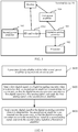

Classifications
-
- H—ELECTRICITY
- H03—ELECTRONIC CIRCUITRY
- H03F—AMPLIFIERS
- H03F3/00—Amplifiers with only discharge tubes or only semiconductor devices as amplifying elements
- H03F3/181—Low-frequency amplifiers, e.g. audio preamplifiers
- H03F3/183—Low-frequency amplifiers, e.g. audio preamplifiers with semiconductor devices only
- H03F3/185—Low-frequency amplifiers, e.g. audio preamplifiers with semiconductor devices only with field-effect devices
-
- H—ELECTRICITY
- H03—ELECTRONIC CIRCUITRY
- H03F—AMPLIFIERS
- H03F3/00—Amplifiers with only discharge tubes or only semiconductor devices as amplifying elements
- H03F3/20—Power amplifiers, e.g. Class B amplifiers, Class C amplifiers
- H03F3/21—Power amplifiers, e.g. Class B amplifiers, Class C amplifiers with semiconductor devices only
- H03F3/217—Class D power amplifiers; Switching amplifiers
- H03F3/2175—Class D power amplifiers; Switching amplifiers using analogue-digital or digital-analogue conversion
-
- H—ELECTRICITY
- H03—ELECTRONIC CIRCUITRY
- H03F—AMPLIFIERS
- H03F3/00—Amplifiers with only discharge tubes or only semiconductor devices as amplifying elements
- H03F3/68—Combinations of amplifiers, e.g. multi-channel amplifiers for stereophonics
-
- H—ELECTRICITY
- H04—ELECTRIC COMMUNICATION TECHNIQUE
- H04Q—SELECTING
- H04Q3/00—Selecting arrangements
-
- H—ELECTRICITY
- H04—ELECTRIC COMMUNICATION TECHNIQUE
- H04R—LOUDSPEAKERS, MICROPHONES, GRAMOPHONE PICK-UPS OR LIKE ACOUSTIC ELECTROMECHANICAL TRANSDUCERS; ELECTRIC HEARING AIDS; PUBLIC ADDRESS SYSTEMS
- H04R29/00—Monitoring arrangements; Testing arrangements
-
- H—ELECTRICITY
- H04—ELECTRIC COMMUNICATION TECHNIQUE
- H04R—LOUDSPEAKERS, MICROPHONES, GRAMOPHONE PICK-UPS OR LIKE ACOUSTIC ELECTROMECHANICAL TRANSDUCERS; ELECTRIC HEARING AIDS; PUBLIC ADDRESS SYSTEMS
- H04R3/00—Circuits for transducers
- H04R3/12—Circuits for transducers for distributing signals to two or more loudspeakers
-
- H—ELECTRICITY
- H03—ELECTRONIC CIRCUITRY
- H03F—AMPLIFIERS
- H03F2200/00—Indexing scheme relating to amplifiers
- H03F2200/03—Indexing scheme relating to amplifiers the amplifier being designed for audio applications
-
- H—ELECTRICITY
- H04—ELECTRIC COMMUNICATION TECHNIQUE
- H04R—LOUDSPEAKERS, MICROPHONES, GRAMOPHONE PICK-UPS OR LIKE ACOUSTIC ELECTROMECHANICAL TRANSDUCERS; ELECTRIC HEARING AIDS; PUBLIC ADDRESS SYSTEMS
- H04R2420/00—Details of connection covered by H04R, not provided for in its groups
- H04R2420/03—Connection circuits to selectively connect loudspeakers or headphones to amplifiers
-
- H—ELECTRICITY
- H04—ELECTRIC COMMUNICATION TECHNIQUE
- H04R—LOUDSPEAKERS, MICROPHONES, GRAMOPHONE PICK-UPS OR LIKE ACOUSTIC ELECTROMECHANICAL TRANSDUCERS; ELECTRIC HEARING AIDS; PUBLIC ADDRESS SYSTEMS
- H04R2420/00—Details of connection covered by H04R, not provided for in its groups
- H04R2420/05—Detection of connection of loudspeakers or headphones to amplifiers
-
- H—ELECTRICITY
- H04—ELECTRIC COMMUNICATION TECHNIQUE
- H04R—LOUDSPEAKERS, MICROPHONES, GRAMOPHONE PICK-UPS OR LIKE ACOUSTIC ELECTROMECHANICAL TRANSDUCERS; ELECTRIC HEARING AIDS; PUBLIC ADDRESS SYSTEMS
- H04R2420/00—Details of connection covered by H04R, not provided for in its groups
- H04R2420/09—Applications of special connectors, e.g. USB, XLR, in loudspeakers, microphones or headphones
-
- H—ELECTRICITY
- H04—ELECTRIC COMMUNICATION TECHNIQUE
- H04R—LOUDSPEAKERS, MICROPHONES, GRAMOPHONE PICK-UPS OR LIKE ACOUSTIC ELECTROMECHANICAL TRANSDUCERS; ELECTRIC HEARING AIDS; PUBLIC ADDRESS SYSTEMS
- H04R5/00—Stereophonic arrangements
- H04R5/04—Circuit arrangements, e.g. for selective connection of amplifier inputs/outputs to loudspeakers, for loudspeaker detection, or for adaptation of settings to personal preferences or hearing impairments
Definitions
- the present invention relates to the field of mobile communications, and in particular, to a terminal device, and a signal sending method and apparatus.
- HIFI High Fidelity
- US 2012/294454A1 refers to a mobile phone apparatus provided with a five conductor earphone jack, etc., which is used to be shared between four and five conductor earphone plugs. Also, the two plugs have a left audio terminal at the same position, but a right audio terminal and a GND terminal at opposite positions.
- a tone signal is output from a third jack terminal.
- a tone signal is output as a leakage signal from a first jack terminal through a four conductor earphone. Then, the leakage signal is amplified, and input to a controlling circuit.
- the five conductor earphone plug is inserted, a leakage signal is not output.
- KR 2002 0095956A refers to a microphone converting a voice signal into an electrical signal to output the electrical signal.
- the first audio amplifier amplifies an output of the microphone to transmit the output to one side of a plug.
- the second audio amplifier amplifies a voice signal outputted through the plug to output the signal to a speaker.
- the speaker delivers an output of the second audio amplifier outside.
- the plug transmits an output signal of the first audio amplifier to a terminal body, and transmits an output signal outputted through an ear jack to the second audio amplifier.
- a power connection socket is electrically connected to a power connector.
- a low voltage converter converts a battery power to supply a driving power to the first and the second audio amplifiers.
- CN 104 348 945 A refers to an audio power amplification device, a mobile telephone and a control method thereof.
- the audio power amplification device comprises a circuit main board, a first audio power amplifier and a second audio amplifier, the audio power amplification device also comprises a detection module, the second audio power amplifier and the detection module are arranged on the circuit main board, the detection module is used for detecting whether the second audio power amplifier sends an audio signal to the first audio power amplifier, if the second audio power amplifier sends an audio signal to the first audio power amplifier, the detection module sends a trigger signal to the first power amplifier, and then the first audio power amplifier is in a working state.
- a preset power amplifier (Power Amplifier, PA) is mounted on a terminal device. Therefore, when the terminal plays audio, an audio stream can only select a built-in PA channel, to achieve a preset HIFI audio effect, that is, different HIFI effects cannot be achieved.
- PA Power Amplifier
- the prior art has a problem that a terminal device can support only one type of PA, affecting user experience.
- Embodiments of the present invention provide a terminal device, and a signal sending method and apparatus, so as to resolve a problem in the prior art that a terminal device can support only one type of PA, affecting user experience.
- terminal device comprises:
- the processor is further configured to: receive a first power amplifier selection instruction entered by a user, and output the second digital signal according to the first power amplifier selection instruction.
- the power amplifier is disposed on the substrate by using a surface-mount technology SMT, wherein the pins on the substrate are edge connectors.
- a signal sending method performed by a terminal device comprising:
- the method further comprises: receiving, by the processor, a first power amplifier selection instruction entered by a user, and sending, by the processor, the second digital signal to the digital-to-analog converter according to the first power amplifier selection instruction.
- the embodiments of the present invention provide a terminal device, and a signal sending method and apparatus.
- the terminal device includes: an access unit, a processor, a digital-to-analog converter, a built-in first power amplifier, and a detachable second power amplifier, where the access unit is connected between a headset or an audio speaker and the digital-to-analog converter, and is configured for insertion of the detachable second power amplifier;
- the processor is configured to detect whether the second power amplifier is inserted into the access unit, output a first digital signal when detecting that the second power amplifier is inserted into the access unit, and output a second digital signal when detecting that the second power amplifier is not inserted into the access unit;
- the digital-to-analog converter is connected to the processor, and is configured to: when receiving the first digital signal, convert the first digital signal to a first analog signal, and send the first analog signal to the second power amplifier; and when receiving the second digital signal, convert the second digital signal to a second analog signal, and send the second analog
- the terminal device provided in the present invention may be a mobile terminal such as a mobile phone, a notebook computer, or a tablet computer.
- FIG. 1 is a first schematic diagram of a terminal device according to a first embodiment of the present invention.
- the terminal device 10 includes: an access unit 101, a processor 102, a digital-to-analog converter 103, a built-in first power amplifier 104, and a detachable second power amplifier 105.
- the access unit 101 is connected between a headset or an audio speaker and the digital-to-analog converter 103, and is configured for insertion of the detachable second power amplifier 105.
- the access unit 101 may be a male connector 1011, or a secure digital (Secure Digital Memory Card, SD) card socket 1012.
- the processor 102 may be an application processor (Application Processor, AP), which is connected to the digital-to-analog converter 103. That is, the processor 102 may receive a digital signal from the digital-to-analog converter 103, or may send a digital signal to the digital-to-analog converter 103.
- Application Processor Application Processor
- the digital-to-analog converter 103 may be a digital-to-analog converter (Digital to Analog Converter, DAC) chip, which is connected to both the access unit 101 and the first power amplifier 104. That is, the digital-to-analog converter 103 converts the digital signal received from the processor 102, and sends, to the first power amplifier 104, an analog signal obtained after the conversion. Alternatively, after the second power amplifier 105 is inserted into the access unit 101, the digital-to-analog converter 103 sends, to the second power amplifier 105, an analog signal obtained after the conversion. Finally, the first power amplifier 104 or the second power amplifier 105 forwards the analog signal to the headset or audio speaker, and the headset or the audio speaker plays sound.
- DAC Digital to Analog Converter
- FIG. 2 is a second schematic diagram of a terminal device according to a second embodiment of the present invention.
- the access unit 101 is a male connector 1011.
- the male connector 1011 is provided with pins.
- the second power amplifier 105 is a pin power amplifier.
- the pin power amplifier may be any pin power amplifier in the prior art. In this way, a user has more choices when selecting a power amplifier.
- FIG. 3 is a third schematic diagram of a terminal device according to a third embodiment of the present invention.
- the access unit 101 is the SD card socket 1012.
- the SD card socket is also provided with pins. Preferably, there are eight pins.
- the second power amplifier 105 includes: a substrate, and a power amplifier disposed on the substrate.
- the power amplifier may be disposed on the substrate by using a surface-mount technology (Surface Mount Technology, SMT). Pins on the substrate are connected to the pins on the SD card socket after the substrate is plug-connected to the SD card socket.
- SMT Surface Mount Technology
- a size and a shape of the substrate match those of the SD card on the terminal device.
- the pins on the substrate are edge connectors, so that an overall thickness of the terminal device is less than a threshold, and different second power amplifiers 105 are easily removed and replaced.
- the access unit 101 may be another socket.
- the socket has a same design structure (such as a pin structure) as the SD card socket.
- the processor 102 is configured to: detect whether the second power amplifier 105 is inserted into the access unit 101; output a first digital signal when detecting that the second power amplifier 105 is inserted into the access unit 101; and output a second digital signal when detecting that the second power amplifier 105 is not inserted into the access unit 101.
- the processor 102 when detecting that the second power amplifier 105 is inserted into the access unit 101, the processor 102 is further configured to: receive a second power amplifier selection instruction entered by a user, where the second power amplifier selection instruction is used to trigger the processor 102 to detect a power supply status of the second power amplifier 105; and output the first digital signal when the power supply status of the second power amplifier 105 is a normal state.
- the processor 102 is configured to: receive a first power amplifier selection instruction entered by a user, and output the second digital signal according to the first power amplifier selection instruction.
- the pins of the male connector change into a low level, so that an input level collected in a collection period by the processor 102 is low level.
- the processor 102 determines that the pin power amplifier is inserted into the male connector, that is, it is detected that the second power amplifier 105 is inserted into the access unit 101, and the processor 102 outputs the first digital signal.
- a UI interface may be loaded. A user enters a second power amplifier selection instruction or a first power amplifier selection instruction by using the UI interface.
- the processor 102 After receiving the second power amplifier selection instruction, the processor 102 detects a power supply status of the second power amplifier 105, that is, detects whether a circuit connection between the second power amplifier 105 and a power supply source is normal. If the circuit connection is normal, the processor 102 outputs the first digital signal. Alternatively, after receiving the first power amplifier selection instruction, the processor 102 outputs the second digital signal according to the first power amplifier selection instruction
- the digital-to-analog converter 103 is connected to the processor 102, and is configured to: when receiving the first digital signal, convert the first digital signal to a first analog signal, and send the first analog signal to the second power amplifier 105; and when receiving the second digital signal, convert the second digital signal to a second analog signal, and send the second analog signal to the first power amplifier 104.
- the processor 102 detects that the second power amplifier 105 is inserted into the access unit 101, and receives the second power amplifier selection instruction entered by the user, an audio stream during playback by the headset automatically selects a channel that passes the second power amplifier 105. That is, the processor 102 transmits the first digital signal to the digital-to-analog converter 103, and a first analog signal output by the digital-to-analog converter 103 is transmitted to the second power amplifier 105.
- the second power amplifier 105 amplifies and sends the received first analog signal to the headset to play. In this case, the first power amplifier 104 is disabled.
- the processor 102 After the processor 102 detects that the second power amplifier 105 is inserted into the access unit 101, and receives the first power amplifier selection instruction entered by the user, the audio stream during playback by the headset selects by default a channel that passes the first power amplifier 104. That is, the processor 102 transmits the second digital signal to the digital-to-analog converter 103, and a second analog signal output by the digital-to-analog converter 103 is transmitted to the first power amplifier 104, and the first power amplifier 104 amplifies and sends the received second analog signal to the headset to play. In this case, the second power amplifier 105 is disabled.
- the terminal device includes: an access unit, a processor, a digital-to-analog converter, a built-in first power amplifier, and a detachable second power amplifier, where the access unit is connected between a headset or an audio speaker and the digital-to-analog converter, and is configured for insertion of the detachable second power amplifier;
- the processor is configured to detect whether the second power amplifier is inserted into the access unit, output a first digital signal when detecting that the second power amplifier is inserted into the access unit, and output a second digital signal when detecting that the second power amplifier is not inserted into the access unit;
- the digital-to-analog converter is connected to the processor, and is configured to: when receiving the first digital signal, convert the first digital signal to a first analog signal, and send the first analog signal to the second power amplifier, and when receiving the second digital signal, convert the second digital signal to a second analog signal, and send the second analog signal to the first power amplifier.
- the terminal device may be compatible with multiple PA
- FIG. 4 is a flowchart of a signal sending method according to a fourth embodiment of the present invention. The method may be performed by the processor 102 in FIG. 1 . As shown in FIG. 4 , the method may include the following steps.
- Step 410 The processor detects whether a detachable second power amplifier is inserted into an access unit.
- the access unit may be a male connector.
- the male connector is provided with pins.
- the second power amplifier may be a pin power amplifier.
- the access unit may be a secure digital SD card socket.
- the SD card socket is provided with pins.
- the second power amplifier includes: a substrate, and a power amplifier disposed on the substrate by using a surface-mount technology SMT. Pins on the substrate are connected to the pins on the SD card socket after the substrate is plug-connected to the SD card socket.
- the pins on the substrate are edge connectors.
- Step 420 Send a first digital signal to a digital-to-analog converter when it is detected that the second power amplifier is inserted into the access unit, so that the digital-to-analog converter converts the first digital signal to a first analog signal, and sends the first analog signal to the second power amplifier.
- Step 430 Send a second digital signal to the digital-to-analog converter when it is detected that the second power amplifier is not inserted into the access unit, so that the digital-to-analog converter converts the second digital signal to a second analog signal, and sends the second analog signal to a first power amplifier.
- the method further includes: receiving a second power amplifier selection instruction entered by a user, where the second power amplifier selection instruction is used to trigger the processor to detect a power supply status of the second power amplifier; and sending the first digital signal to the digital-to-analog converter when the power supply status of the second power amplifier is a normal state.
- the method further includes: receiving a first power amplifier selection instruction entered by a user, and sending the second digital signal to the digital-to-analog converter according to the first power amplifier selection instruction.
- the signal sending method provided in this embodiment of the present invention includes: detecting, by a processor, whether a detachable second power amplifier is inserted into an access unit; sending a first digital signal to a digital-to-analog converter when it is detected that the second power amplifier is inserted into the access unit, so that the digital-to-analog converter converts the first digital signal to a first analog signal, and sends the first analog signal to the second power amplifier; and sending a second digital signal to the digital-to-analog converter when it is detected that the second power amplifier is not inserted into the access unit, so that the digital-to-analog converter converts the second digital signal to a second analog signal, and sends the second analog signal to the first power amplifier.
- the terminal device may be compatible with multiple PAs, so that users of the terminal device may pair different headsets with different sound sources by themselves, improving user experience.
- FIG. 5 is a schematic diagram of a signal sending apparatus according to a fifth embodiment of the present invention.
- the apparatus includes: an access unit 501, a detection unit 502, and a sending unit 503.
- the access unit 501 is configured for insertion of a detachable second power amplifier.
- the access unit 501 is a male connector, the male connector is provided with pins, and the second power amplifier is a pin power amplifier.
- the access unit 501 is a secure digital SD card socket.
- the SD card socket is provided with pins.
- the second power amplifier includes: a substrate, and a power amplifier disposed on the substrate. Pins on the substrate are connected to the pins on the SD card socket after the substrate is plug-connected to the SD card socket.
- the power amplifier is disposed on the substrate by using a surface-mount technology SMT.
- the pins of the substrate are edge connectors.
- the detection unit 502 is configured to detect whether the detachable second power amplifier is inserted into the access unit 501.
- the sending unit 503 is configured to send a first digital signal to a digital-to-analog converter when the detection unit 502 detects that the second power amplifier is inserted into the access unit 501, so that the digital-to-analog converter converts the first digital signal to a first analog signal, and sends the first analog signal to the second power amplifier.
- the sending unit 503 is further configured to send a second digital signal to the digital-to-analog converter when the detection unit 502 detects that the second power amplifier is not inserted into the access unit 501, so that the digital-to-analog converter converts the second digital signal to a second analog signal, and sends the second analog signal to a first power amplifier.
- the apparatus further includes: a receiving unit 504, configured to: receive a second power amplifier selection instruction entered by a user, where the second power amplifier selection instruction is used to trigger the detection unit 502 to detect a power supply status of the second power amplifier; and send the first digital signal to the digital-to-analog converter when the power supply status of the second power amplifier is a normal state.
- a receiving unit 504 configured to: receive a second power amplifier selection instruction entered by a user, where the second power amplifier selection instruction is used to trigger the detection unit 502 to detect a power supply status of the second power amplifier; and send the first digital signal to the digital-to-analog converter when the power supply status of the second power amplifier is a normal state.
- the receiving unit 504 is further configured to: receive a first power amplifier selection instruction entered by a user, and send the second digital signal to the digital-to-analog converter according to the first power amplifier selection instruction.
- the method provided in the method embodiment of the present invention is embedded in the apparatus provided in the apparatus embodiment of the present invention. Therefore, a specific operating process of the apparatus provided in the present invention is not described herein.
- the signal sending apparatus provided in this embodiment of the present invention may be compatible with multiple PAs, so that mobile phone users may pair different headsets with sound sources, improving user experience.
- FIG. 6 is a schematic diagram of a signal sending device according to a sixth embodiment of the present invention.
- the sending device 600 includes: a processor 602, a memory 604, a communications interface 606, and a bus 608.
- the processor 602, the memory 604, and the communications interface 606 communicate with each other by using the bus 608.
- the processor 602 may use a general-purpose central processing unit (Central Processing Unit, CPU), a microprocessor, an application-specific integrated circuit (Application Specific Integrated Circuit, ASIC), or one or more integrated circuits to execute a related program, to implement the technical solution provided in the fourth embodiment of the present invention.
- CPU Central Processing Unit
- ASIC Application Specific Integrated Circuit
- the memory 604 may be a read-only memory (Read Only Memory, ROM), a static storage device, a dynamic storage device, or a random access memory (Random Access Memory, RAM).
- the memory 604 may store an operating system and another application program.
- program code for implementing the technical solution provided in this embodiment of the present invention is stored in the memory 604, and is executed by the processor 602.
- the communications interface 606 is configured to communicate with another device.
- the bus 608 may include a channel for transmitting information among each element (such as the processor 602, the memory 604, and the communications interface 606) of the sending device 600.
- the program code in the memory 604 is accessed by the processor 602, to execute the following instruction:
- the 602 processor is further configured to execute an instruction having the following process: receiving a second power amplifier selection instruction entered by a user, where the second power amplifier selection instruction is used to trigger the processor to detect a power supply status of the second power amplifier; and sending the first digital signal to the digital-to-analog converter when the power supply status of the second power amplifier is a normal state.
- the 602 processor is configured to execute an instruction having the following process: receiving a first power amplifier selection instruction entered by a user, and sending the second digital signal to the digital-to-analog converter according to the first power amplifier selection instruction.
- the access unit is a male connector
- the male connector is provided with pins
- the second power amplifier is a pin power amplifier
- the access unit is a secure digital SD card socket.
- the SD card socket is provided with pins.
- the second power amplifier includes: a substrate, and a power amplifier disposed on the substrate. Pins on the substrate are connected to the pins on the SD card socket after the substrate is plug-connected to the SD card socket.
- the power amplifier is disposed on the substrate by using a surface-mount technology SMT.
- the pins of the substrate are edge connectors.
- the signal sending device provided in this embodiment of the present invention may be compatible with multiple PAs, so that mobile phone users may pair different headsets with sound sources, improving user experience.
- Steps of methods or algorithms described in the embodiments disclosed in this specification may be implemented by hardware, a software module executed by a processor, or a combination thereof.
- the software module may reside in a random access memory (RAM), a memory, a read-only memory (ROM), an electrically programmable ROM, an electrically erasable programmable ROM, a register, a hard disk, a removable disk, a CD-ROM, or any other form of storage medium known in the art.
Landscapes
- Engineering & Computer Science (AREA)
- Power Engineering (AREA)
- Health & Medical Sciences (AREA)
- General Health & Medical Sciences (AREA)
- Otolaryngology (AREA)
- Physics & Mathematics (AREA)
- Acoustics & Sound (AREA)
- Signal Processing (AREA)
- Computer Networks & Wireless Communication (AREA)
- Multimedia (AREA)
- Amplifiers (AREA)
- Power Sources (AREA)
- Circuit For Audible Band Transducer (AREA)
Description
- The present invention relates to the field of mobile communications, and in particular, to a terminal device, and a signal sending method and apparatus.
- As high fidelity (High Fidelity, HIFI) technologies of mobile phones become popular, users hope to pair headsets with sound sources of terminal devices by themselves, to achieve an optimal effect.
- For example,
US 2012/294454A1 refers to a mobile phone apparatus provided with a five conductor earphone jack, etc., which is used to be shared between four and five conductor earphone plugs. Also, the two plugs have a left audio terminal at the same position, but a right audio terminal and a GND terminal at opposite positions. When the earphone plug is inserted, a tone signal is output from a third jack terminal. At this time, if the four conductor earphone plug is inserted, a tone signal is output as a leakage signal from a first jack terminal through a four conductor earphone. Then, the leakage signal is amplified, and input to a controlling circuit. On the other hand, if the five conductor earphone plug is inserted, a leakage signal is not output. - Further,
KR 2002 0095956A - Further,
CN 104 348 945 A - In the prior art, a preset power amplifier (Power Amplifier, PA) is mounted on a terminal device. Therefore, when the terminal plays audio, an audio stream can only select a built-in PA channel, to achieve a preset HIFI audio effect, that is, different HIFI effects cannot be achieved.
- As can be learned from the above, the prior art has a problem that a terminal device can support only one type of PA, affecting user experience.
- Embodiments of the present invention provide a terminal device, and a signal sending method and apparatus, so as to resolve a problem in the prior art that a terminal device can support only one type of PA, affecting user experience.
- In a first aspect a terminal device, wherein the terminal device comprises:
- an access unit, a processor, a digital-to-analog converter, a built-in first power amplifier, and a detachable second power amplifier,
- o wherein the access unit is a secure digital, SD, card socket, wherein the SD card socket is provided with pins, and
- o the detachable second power amplifier comprises: a substrate, a power amplifier disposed on the substrate, and pins on the substrate, wherein the pins on the substrate are connected to the pins on the SD card socket after the substrate is plug-connected to the SD card socket, wherein:
- the access unit is connected between a headset or an audio speaker and the digital-to-analog converter, and is configured to enable an insertion of the detachable second power amplifier;
- the processor is configured to: detect whether the detachable second power amplifier is inserted into the access unit, send a first digital signal to the digital-to-analog converter if detecting that the detachable second power amplifier is inserted into the access unit; and send a second digital signal to the digital-to-analog converter if detecting that the detachable second power amplifier is not inserted into the access unit; and
- the digital-to-analog converter is connected to the processor, and is configured to: if receiving the first digital signal, convert the first digital signal to a first analog signal and send the first analog signal to the detachable second power amplifier; and if receiving the second digital signal, convert the second digital signal to a second analog signal and send the second analog signal to the first power amplifier.
- In a first implementation form of the first aspect the processor is further configured to: receive a first power amplifier selection instruction entered by a user, and output the second digital signal according to the first power amplifier selection instruction.
- In a second implementation form of the first aspect the power amplifier is disposed on the substrate by using a surface-mount technology SMT, wherein the pins on the substrate are edge connectors.
- In a second aspect a signal sending method performed by a terminal device according to the first aspect is provided, wherein the method comprises:
- detecting, by the processor, whether the detachable second power amplifier is inserted into the access unit;
- sending, by the processor, the first digital signal to the digital-to-analog converter if it is detected that the second power amplifier is inserted into the access unit, and converting, by the digital-to-analog converter, the first digital signal to the first analog signal, and sending, by the digital-to-analog converter, the first analog signal to the second power amplifier;
- sending, by the processor, the second digital signal to the digital-to-analog converter if it is detected that the second power amplifier is not inserted into the access unit, and converting, by the digital-to-analog converter, the second digital signal to the second analog signal, and sending, by the digital-to-analog converter, the second analog signal to the first power amplifier.
- In a first implementation form of the second aspect the method further comprises:
receiving, by the processor, a first power amplifier selection instruction entered by a user, and sending, by the processor, the second digital signal to the digital-to-analog converter according to the first power amplifier selection instruction. - The embodiments of the present invention provide a terminal device, and a signal sending method and apparatus. The terminal device includes: an access unit, a processor, a digital-to-analog converter, a built-in first power amplifier, and a detachable second power amplifier, where the access unit is connected between a headset or an audio speaker and the digital-to-analog converter, and is configured for insertion of the detachable second power amplifier; the processor is configured to detect whether the second power amplifier is inserted into the access unit, output a first digital signal when detecting that the second power amplifier is inserted into the access unit, and output a second digital signal when detecting that the second power amplifier is not inserted into the access unit; and the digital-to-analog converter is connected to the processor, and is configured to: when receiving the first digital signal, convert the first digital signal to a first analog signal, and send the first analog signal to the second power amplifier; and when receiving the second digital signal, convert the second digital signal to a second analog signal, and send the second analog signal to the first power amplifier. In this way, the terminal device may be compatible with multiple PAs, so that users of the terminal device may pair different headsets with different sound sources by themselves, improving user experience.
-
-
FIG. 1 is a first schematic diagram of a terminal device according to a first embodiment of the present invention; -
FIG. 2 is a second schematic diagram of a terminal device according to a second embodiment of the present invention; -
FIG. 3 is a third schematic diagram of a terminal device according to a third embodiment of the present invention; -
FIG. 4 is a flowchart of a signal sending method according to a fourth embodiment of the present invention; -
FIG. 5 is a schematic diagram of a signal sending apparatus according to a fifth embodiment of the present invention; and -
FIG. 6 is a schematic diagram of a signal sending device according to a sixth embodiment of the present invention. - The technical solutions of the present invention are further described in detail with reference to accompanying drawings and embodiments as follows:
- To make the objectives, technical solutions, and advantages of the embodiments of the present invention clearer, the following clearly and completely describes the technical solutions in the embodiments of the present invention with reference to the accompanying drawings in the embodiments of the present invention. Apparently, the described embodiments are some but not all of the embodiments of the present invention. All other embodiments obtained by a person of ordinary skill in the art based on the embodiments of the present invention without creative efforts shall fall within the protection scope of the present invention.
- To provide thorough understanding of the embodiments of the present invention, the following further describes specific embodiments in detail with reference to the accompanying drawings. The foregoing embodiments are not intended to limit the protection scope of the present invention.
- The terminal device provided in the present invention may be a mobile terminal such as a mobile phone, a notebook computer, or a tablet computer.
-
FIG. 1 is a first schematic diagram of a terminal device according to a first embodiment of the present invention. InFIG. 1 , theterminal device 10 includes: anaccess unit 101, aprocessor 102, a digital-to-analog converter 103, a built-infirst power amplifier 104, and a detachablesecond power amplifier 105. - As shown in
FIG. 1 , theaccess unit 101 is connected between a headset or an audio speaker and the digital-to-analog converter 103, and is configured for insertion of the detachablesecond power amplifier 105. Theaccess unit 101 may be amale connector 1011, or a secure digital (Secure Digital Memory Card, SD)card socket 1012. Theprocessor 102 may be an application processor (Application Processor, AP), which is connected to the digital-to-analog converter 103. That is, theprocessor 102 may receive a digital signal from the digital-to-analog converter 103, or may send a digital signal to the digital-to-analog converter 103. The digital-to-analog converter 103 may be a digital-to-analog converter (Digital to Analog Converter, DAC) chip, which is connected to both theaccess unit 101 and thefirst power amplifier 104. That is, the digital-to-analog converter 103 converts the digital signal received from theprocessor 102, and sends, to thefirst power amplifier 104, an analog signal obtained after the conversion. Alternatively, after thesecond power amplifier 105 is inserted into theaccess unit 101, the digital-to-analog converter 103 sends, to thesecond power amplifier 105, an analog signal obtained after the conversion. Finally, thefirst power amplifier 104 or thesecond power amplifier 105 forwards the analog signal to the headset or audio speaker, and the headset or the audio speaker plays sound. -
FIG. 2 is a second schematic diagram of a terminal device according to a second embodiment of the present invention. InFIG. 2 , theaccess unit 101 is amale connector 1011. Themale connector 1011 is provided with pins. Preferably, there are eight pins. Thesecond power amplifier 105 is a pin power amplifier. The pin power amplifier may be any pin power amplifier in the prior art. In this way, a user has more choices when selecting a power amplifier. -
FIG. 3 is a third schematic diagram of a terminal device according to a third embodiment of the present invention. InFIG. 3 , theaccess unit 101 is theSD card socket 1012. The SD card socket is also provided with pins. Preferably, there are eight pins. Thesecond power amplifier 105 includes: a substrate, and a power amplifier disposed on the substrate. The power amplifier may be disposed on the substrate by using a surface-mount technology (Surface Mount Technology, SMT). Pins on the substrate are connected to the pins on the SD card socket after the substrate is plug-connected to the SD card socket. - It should be noted that in
FIG. 3 , a size and a shape of the substrate match those of the SD card on the terminal device. Preferably, the pins on the substrate are edge connectors, so that an overall thickness of the terminal device is less than a threshold, and differentsecond power amplifiers 105 are easily removed and replaced. - In addition, a person skilled in the art may design the
access unit 101 to be another socket. The socket has a same design structure (such as a pin structure) as the SD card socket. - In
FIG. 1 , theprocessor 102 is configured to: detect whether thesecond power amplifier 105 is inserted into theaccess unit 101; output a first digital signal when detecting that thesecond power amplifier 105 is inserted into theaccess unit 101; and output a second digital signal when detecting that thesecond power amplifier 105 is not inserted into theaccess unit 101. - Optionally, when detecting that the
second power amplifier 105 is inserted into theaccess unit 101, theprocessor 102 is further configured to: receive a second power amplifier selection instruction entered by a user, where the second power amplifier selection instruction is used to trigger theprocessor 102 to detect a power supply status of thesecond power amplifier 105; and output the first digital signal when the power supply status of thesecond power amplifier 105 is a normal state. - Further, the
processor 102 is configured to: receive a first power amplifier selection instruction entered by a user, and output the second digital signal according to the first power amplifier selection instruction. - Using the terminal device in
FIG. 2 as an example, after the pin power amplifier having eight pins is inserted into the male connector, the pins of the male connector change into a low level, so that an input level collected in a collection period by theprocessor 102 is low level. When the collected input level is a low level, theprocessor 102 determines that the pin power amplifier is inserted into the male connector, that is, it is detected that thesecond power amplifier 105 is inserted into theaccess unit 101, and theprocessor 102 outputs the first digital signal. Optionally, when it is detected that thesecond power amplifier 105 is inserted into theaccess unit 101, a UI interface may be loaded. A user enters a second power amplifier selection instruction or a first power amplifier selection instruction by using the UI interface. After receiving the second power amplifier selection instruction, theprocessor 102 detects a power supply status of thesecond power amplifier 105, that is, detects whether a circuit connection between thesecond power amplifier 105 and a power supply source is normal. If the circuit connection is normal, theprocessor 102 outputs the first digital signal. Alternatively, after receiving the first power amplifier selection instruction, theprocessor 102 outputs the second digital signal according to the first power amplifier selection instruction - In
FIG. 1 , the digital-to-analog converter 103 is connected to theprocessor 102, and is configured to: when receiving the first digital signal, convert the first digital signal to a first analog signal, and send the first analog signal to thesecond power amplifier 105; and when receiving the second digital signal, convert the second digital signal to a second analog signal, and send the second analog signal to thefirst power amplifier 104. - Specifically, when the
processor 102 detects that thesecond power amplifier 105 is inserted into theaccess unit 101, and receives the second power amplifier selection instruction entered by the user, an audio stream during playback by the headset automatically selects a channel that passes thesecond power amplifier 105. That is, theprocessor 102 transmits the first digital signal to the digital-to-analog converter 103, and a first analog signal output by the digital-to-analog converter 103 is transmitted to thesecond power amplifier 105. Thesecond power amplifier 105 amplifies and sends the received first analog signal to the headset to play. In this case, thefirst power amplifier 104 is disabled. After theprocessor 102 detects that thesecond power amplifier 105 is inserted into theaccess unit 101, and receives the first power amplifier selection instruction entered by the user, the audio stream during playback by the headset selects by default a channel that passes thefirst power amplifier 104. That is, theprocessor 102 transmits the second digital signal to the digital-to-analog converter 103, and a second analog signal output by the digital-to-analog converter 103 is transmitted to thefirst power amplifier 104, and thefirst power amplifier 104 amplifies and sends the received second analog signal to the headset to play. In this case, thesecond power amplifier 105 is disabled. - The terminal device provided in this embodiment of the present invention includes: an access unit, a processor, a digital-to-analog converter, a built-in first power amplifier, and a detachable second power amplifier, where the access unit is connected between a headset or an audio speaker and the digital-to-analog converter, and is configured for insertion of the detachable second power amplifier; the processor is configured to detect whether the second power amplifier is inserted into the access unit, output a first digital signal when detecting that the second power amplifier is inserted into the access unit, and output a second digital signal when detecting that the second power amplifier is not inserted into the access unit; and the digital-to-analog converter is connected to the processor, and is configured to: when receiving the first digital signal, convert the first digital signal to a first analog signal, and send the first analog signal to the second power amplifier, and when receiving the second digital signal, convert the second digital signal to a second analog signal, and send the second analog signal to the first power amplifier. In this way, the terminal device may be compatible with multiple PAs, so that users of the terminal device may pair different headsets with different sound sources by themselves, improving user experience.
-
FIG. 4 is a flowchart of a signal sending method according to a fourth embodiment of the present invention. The method may be performed by theprocessor 102 inFIG. 1 . As shown inFIG. 4 , the method may include the following steps. - Step 410. The processor detects whether a detachable second power amplifier is inserted into an access unit.
- The access unit may be a male connector. The male connector is provided with pins. Preferably, there are eight pins. The second power amplifier may be a pin power amplifier.
- Alternatively, the access unit may be a secure digital SD card socket. The SD card socket is provided with pins. Preferably, there are eight pins. The second power amplifier includes: a substrate, and a power amplifier disposed on the substrate by using a surface-mount technology SMT. Pins on the substrate are connected to the pins on the SD card socket after the substrate is plug-connected to the SD card socket. Preferably, the pins on the substrate are edge connectors.
-
Step 420. Send a first digital signal to a digital-to-analog converter when it is detected that the second power amplifier is inserted into the access unit, so that the digital-to-analog converter converts the first digital signal to a first analog signal, and sends the first analog signal to the second power amplifier. - Step 430. Send a second digital signal to the digital-to-analog converter when it is detected that the second power amplifier is not inserted into the access unit, so that the digital-to-analog converter converts the second digital signal to a second analog signal, and sends the second analog signal to a first power amplifier.
- Optionally, when it is detected that the second power amplifier is inserted into the access unit, the method further includes:
receiving a second power amplifier selection instruction entered by a user, where the second power amplifier selection instruction is used to trigger the processor to detect a power supply status of the second power amplifier; and sending the first digital signal to the digital-to-analog converter when the power supply status of the second power amplifier is a normal state. - Optionally, the method further includes:
receiving a first power amplifier selection instruction entered by a user, and sending the second digital signal to the digital-to-analog converter according to the first power amplifier selection instruction. - The signal sending method provided in this embodiment of the present invention includes: detecting, by a processor, whether a detachable second power amplifier is inserted into an access unit; sending a first digital signal to a digital-to-analog converter when it is detected that the second power amplifier is inserted into the access unit, so that the digital-to-analog converter converts the first digital signal to a first analog signal, and sends the first analog signal to the second power amplifier; and sending a second digital signal to the digital-to-analog converter when it is detected that the second power amplifier is not inserted into the access unit, so that the digital-to-analog converter converts the second digital signal to a second analog signal, and sends the second analog signal to the first power amplifier. In this way, the terminal device may be compatible with multiple PAs, so that users of the terminal device may pair different headsets with different sound sources by themselves, improving user experience.
-
FIG. 5 is a schematic diagram of a signal sending apparatus according to a fifth embodiment of the present invention. InFIG. 5 , the apparatus includes: anaccess unit 501, adetection unit 502, and a sendingunit 503. - The
access unit 501 is configured for insertion of a detachable second power amplifier. - Optionally, the
access unit 501 is a male connector, the male connector is provided with pins, and the second power amplifier is a pin power amplifier. - Optionally, the
access unit 501 is a secure digital SD card socket. The SD card socket is provided with pins. The second power amplifier includes: a substrate, and a power amplifier disposed on the substrate. Pins on the substrate are connected to the pins on the SD card socket after the substrate is plug-connected to the SD card socket. - Further, the power amplifier is disposed on the substrate by using a surface-mount technology SMT. The pins of the substrate are edge connectors.
- The
detection unit 502 is configured to detect whether the detachable second power amplifier is inserted into theaccess unit 501. - The sending
unit 503 is configured to send a first digital signal to a digital-to-analog converter when thedetection unit 502 detects that the second power amplifier is inserted into theaccess unit 501, so that the digital-to-analog converter converts the first digital signal to a first analog signal, and sends the first analog signal to the second power amplifier. - The sending
unit 503 is further configured to send a second digital signal to the digital-to-analog converter when thedetection unit 502 detects that the second power amplifier is not inserted into theaccess unit 501, so that the digital-to-analog converter converts the second digital signal to a second analog signal, and sends the second analog signal to a first power amplifier. - Optionally, the apparatus further includes: a receiving unit 504, configured to: receive a second power amplifier selection instruction entered by a user, where the second power amplifier selection instruction is used to trigger the
detection unit 502 to detect a power supply status of the second power amplifier; and send the first digital signal to the digital-to-analog converter when the power supply status of the second power amplifier is a normal state. - The receiving unit 504 is further configured to: receive a first power amplifier selection instruction entered by a user, and send the second digital signal to the digital-to-analog converter according to the first power amplifier selection instruction.
- The method provided in the method embodiment of the present invention is embedded in the apparatus provided in the apparatus embodiment of the present invention. Therefore, a specific operating process of the apparatus provided in the present invention is not described herein.
- In this way, the signal sending apparatus provided in this embodiment of the present invention may be compatible with multiple PAs, so that mobile phone users may pair different headsets with sound sources, improving user experience.
-
FIG. 6 is a schematic diagram of a signal sending device according to a sixth embodiment of the present invention. InFIG. 6 , the sendingdevice 600 includes: aprocessor 602, amemory 604, acommunications interface 606, and a bus 608. Theprocessor 602, thememory 604, and thecommunications interface 606 communicate with each other by using the bus 608. - The
processor 602 may use a general-purpose central processing unit (Central Processing Unit, CPU), a microprocessor, an application-specific integrated circuit (Application Specific Integrated Circuit, ASIC), or one or more integrated circuits to execute a related program, to implement the technical solution provided in the fourth embodiment of the present invention. - The
memory 604 may be a read-only memory (Read Only Memory, ROM), a static storage device, a dynamic storage device, or a random access memory (Random Access Memory, RAM). Thememory 604 may store an operating system and another application program. When the technical solution provided in this embodiment of the present invention is implemented by using software or firmware, program code for implementing the technical solution provided in this embodiment of the present invention is stored in thememory 604, and is executed by theprocessor 602. - The
communications interface 606 is configured to communicate with another device. - The bus 608 may include a channel for transmitting information among each element (such as the
processor 602, thememory 604, and the communications interface 606) of the sendingdevice 600. - When the sending
device 600 is running, the program code in thememory 604 is accessed by theprocessor 602, to execute the following instruction: - detecting whether a detachable second power amplifier is inserted into an access unit;
- sending a first digital signal to a digital-to-analog converter when detecting that the second power amplifier is inserted into the access unit, so that the digital-to-analog converter converts the first digital signal to a first analog signal, and sends the first analog signal to the second power amplifier; and
- sending a second digital signal to the digital-to-analog converter when detecting that the second power amplifier is not inserted into the access unit, so that the digital-to-analog converter converts the second digital signal to a second analog signal, and sends the second analog signal to a first power amplifier.
- Further, the 602 processor is further configured to execute an instruction having the following process:
receiving a second power amplifier selection instruction entered by a user, where the second power amplifier selection instruction is used to trigger the processor to detect a power supply status of the second power amplifier; and sending the first digital signal to the digital-to-analog converter when the power supply status of the second power amplifier is a normal state. - Further, the 602 processor is configured to execute an instruction having the following process:
receiving a first power amplifier selection instruction entered by a user, and sending the second digital signal to the digital-to-analog converter according to the first power amplifier selection instruction. - Optionally, the access unit is a male connector, the male connector is provided with pins, and the second power amplifier is a pin power amplifier.
- Optionally, the access unit is a secure digital SD card socket. The SD card socket is provided with pins. The second power amplifier includes: a substrate, and a power amplifier disposed on the substrate. Pins on the substrate are connected to the pins on the SD card socket after the substrate is plug-connected to the SD card socket.
- The power amplifier is disposed on the substrate by using a surface-mount technology SMT. The pins of the substrate are edge connectors.
- In this way, the signal sending device provided in this embodiment of the present invention may be compatible with multiple PAs, so that mobile phone users may pair different headsets with sound sources, improving user experience.
- A person skilled in the art may be further aware that, in combination with the examples described in the embodiments disclosed in this specification, units and algorithm steps may be implemented by electronic hardware, computer software, or a combination thereof. To clearly describe the interchangeability between the hardware and the software, the foregoing has generally described compositions and steps of each example according to functions. Whether the functions are performed by hardware or software depends on particular applications and design constraint conditions of the technical solutions. A person skilled in the art may use different methods to implement the described functions for each particular application, but it should not be considered that the implementation goes beyond the scope of the present invention defined by the claims.
- Steps of methods or algorithms described in the embodiments disclosed in this specification may be implemented by hardware, a software module executed by a processor, or a combination thereof. The software module may reside in a random access memory (RAM), a memory, a read-only memory (ROM), an electrically programmable ROM, an electrically erasable programmable ROM, a register, a hard disk, a removable disk, a CD-ROM, or any other form of storage medium known in the art.
- In the foregoing specific implementation manners, the objective, technical solutions, and benefits of the present invention are further described in detail. It should be understood that the foregoing descriptions are merely specific implementation manners of the present invention, but are not intended to limit the protection scope of the present invention defined by the claims.
Claims (5)
- A terminal device (10), wherein the terminal device (10) comprises:• an access unit (1012), a processor (102), a digital-to-analog converter (103), a built-in first power amplifier (104), and a detachable second power amplifier (105),∘ wherein the access unit (1012) is a secure digital, SD, card socket, wherein the SD card socket is provided with pins, and∘ the detachable second power amplifier (105) comprises: a substrate, a power amplifier disposed on the substrate, and pins on the substrate, wherein the pins on the substrate are connected to the pins on the SD card socket after the substrate is plug-connected to the SD card socket, wherein:• the access unit (1012) is connected between a headset or an audio speaker and the digital-to-analog converter (103), and is configured to enable an insertion of the detachable second power amplifier (105);• the processor (102) is configured to: detect whether the detachable second power amplifier (105) is inserted into the access unit (1012), send a first digital signal to the digital-to-analog converter (103) if detecting that the detachable second power amplifier (105) is inserted into the access unit (1012); and send a second digital signal to the digital-to-analog converter (103) if detecting that the detachable second power amplifier (105) is not inserted into the access unit (1012); and• the digital-to-analog converter (103) is connected to the processor (102), and is configured to: if receiving the first digital signal, convert the first digital signal to a first analog signal and send the first analog signal to the detachable second power amplifier (105); and if receiving the second digital signal, convert the second digital signal to a second analog signal and send the second analog signal to the first power amplifier (104).
- The terminal device according to claim 1, wherein the processor is further configured to: receive a first power amplifier selection instruction entered by a user, and output the second digital signal according to the first power amplifier selection instruction.
- The terminal device according to any of claims 1 - 2, wherein the power amplifier is disposed on the substrate by using a surface-mount technology SMT, wherein the pins on the substrate are edge connectors.
- A signal sending method performed by a terminal device according to claim 1, wherein the method comprises:• detecting, by the processor, whether the detachable second power amplifier is inserted into the access unit (S410);• sending, by the processor, the first digital signal to the digital-to-analog converter if it is detected that the second power amplifier is inserted into the access unit, and converting, by the digital-to-analog converter, the first digital signal to the first analog signal, and sending, by the digital-to-analog converter, the first analog signal to the second power amplifier (S 420);• sending, by the processor, the second digital signal to the digital-to-analog converter if it is detected that the second power amplifier is not inserted into the access unit, and converting, by the digital-to-analog converter, the second digital signal to the second analog signal, and sending, by the digital-to-analog converter, the second analog signal to the first power amplifier (S430).
- The method according to claim 4, wherein the method further comprises:
receiving, by the processor, a first power amplifier selection instruction entered by a user, and sending, by the processor, the second digital signal to the digital-to-analog converter according to the first power amplifier selection instruction.
Applications Claiming Priority (1)
| Application Number | Priority Date | Filing Date | Title |
|---|---|---|---|
| PCT/CN2015/074006 WO2016141571A1 (en) | 2015-03-11 | 2015-03-11 | Terminal device, and signal transmission method and device |
Publications (3)
| Publication Number | Publication Date |
|---|---|
| EP3253067A1 EP3253067A1 (en) | 2017-12-06 |
| EP3253067A4 EP3253067A4 (en) | 2018-01-24 |
| EP3253067B1 true EP3253067B1 (en) | 2019-01-30 |
Family
ID=56878689
Family Applications (1)
| Application Number | Title | Priority Date | Filing Date |
|---|---|---|---|
| EP15884254.2A Active EP3253067B1 (en) | 2015-03-11 | 2015-03-11 | Terminal device, and signal transmission method and device |
Country Status (4)
| Country | Link |
|---|---|
| US (1) | US10063198B2 (en) |
| EP (1) | EP3253067B1 (en) |
| CN (1) | CN106464987B (en) |
| WO (1) | WO2016141571A1 (en) |
Families Citing this family (1)
| Publication number | Priority date | Publication date | Assignee | Title |
|---|---|---|---|---|
| CN113490102A (en) * | 2021-07-15 | 2021-10-08 | 恒玄科技(北京)有限公司 | Wireless earphone and communication method thereof |
Family Cites Families (15)
| Publication number | Priority date | Publication date | Assignee | Title |
|---|---|---|---|---|
| JP3495620B2 (en) * | 1998-12-04 | 2004-02-09 | パイオニア株式会社 | BTL amplifier |
| KR100382206B1 (en) * | 2001-06-18 | 2003-05-01 | 엘지전자 주식회사 | Speakerphone and handsfree function circuit in a mobile phone |
| US20050025182A1 (en) * | 2003-06-25 | 2005-02-03 | Ala Nazari | Systems and methods using multiprotocol communication |
| CN2647000Y (en) * | 2003-10-08 | 2004-10-06 | 北京中星微电子有限公司 | Volume regulating device for eliminating noise introduced from volume change |
| US7346315B2 (en) * | 2004-03-30 | 2008-03-18 | Motorola Inc | Handheld device loudspeaker system |
| FR2881005B1 (en) * | 2005-01-18 | 2007-03-30 | Atmel Corp | METHOD AND TOPOLOGY FOR SWITCHING A OUTPUT RANGE IN A CLASS AB AUDIO AMPLIFIER FOR WIRELESS APPLICATIONS |
| JP4909580B2 (en) * | 2005-12-15 | 2012-04-04 | オンセミコンダクター・トレーディング・リミテッド | Signal selection circuit and program |
| CN2919444Y (en) * | 2006-06-09 | 2007-07-04 | 叶勉为 | MP3 player |
| CN101494809B (en) * | 2008-01-24 | 2013-01-09 | 普诚科技股份有限公司 | sound player |
| US20110058692A1 (en) * | 2009-09-09 | 2011-03-10 | Himax Media Solutions, Inc. | Audio output devices |
| CN101867852A (en) * | 2010-07-01 | 2010-10-20 | 深圳市特灵通数码通讯发展有限公司 | Bone conduction earphone based on dual-channel frequency difference and short sound stimulation double actions |
| WO2012082909A2 (en) * | 2010-12-14 | 2012-06-21 | The Regents Of The University Of Michigan | Auxiliary frequency parametric excitation of quadrupole mass spectrometers |
| JP5798943B2 (en) * | 2011-05-20 | 2015-10-21 | 京セラ株式会社 | Mobile terminal, earphone identification program, and earphone identification method |
| CN104348945B (en) * | 2013-08-02 | 2018-09-28 | 上海斐讯数据通信技术有限公司 | Audio power amplifier device, mobile phone and control method |
| CN104254042B (en) * | 2014-07-30 | 2017-05-24 | 宁波音王电声股份有限公司 | Wireless microphone |
-
2015
- 2015-03-11 CN CN201580023182.7A patent/CN106464987B/en active Active
- 2015-03-11 US US15/555,349 patent/US10063198B2/en active Active
- 2015-03-11 WO PCT/CN2015/074006 patent/WO2016141571A1/en not_active Ceased
- 2015-03-11 EP EP15884254.2A patent/EP3253067B1/en active Active
Non-Patent Citations (1)
| Title |
|---|
| None * |
Also Published As
| Publication number | Publication date |
|---|---|
| EP3253067A1 (en) | 2017-12-06 |
| US10063198B2 (en) | 2018-08-28 |
| CN106464987B (en) | 2019-10-22 |
| CN106464987A (en) | 2017-02-22 |
| US20180041178A1 (en) | 2018-02-08 |
| EP3253067A4 (en) | 2018-01-24 |
| WO2016141571A1 (en) | 2016-09-15 |
Similar Documents
| Publication | Publication Date | Title |
|---|---|---|
| CN102143262B (en) | Electronic device and method for switching audio input channel thereof | |
| KR101567362B1 (en) | Apparatus and method for outputting audio signals in portable terminals | |
| KR102105315B1 (en) | Detection circuit | |
| JP5798943B2 (en) | Mobile terminal, earphone identification program, and earphone identification method | |
| US20130101132A1 (en) | Method and Device for Earphone and USB to Share Micro-USB Interface | |
| TWI539830B (en) | Electronic device and audio output control method | |
| CN107517428A (en) | A kind of signal output method and device | |
| CN111247781B (en) | Audio circuit and audio playing system based on intelligent terminal | |
| CN105323680A (en) | audio device | |
| CN102768558A (en) | All-in-one computer having function of muting loudspeaker | |
| CN105828224A (en) | Electronic device, corrector and earphone microphone for correcting electronic device | |
| KR20220160450A (en) | State detection device for use in an audio interface | |
| JP6220731B2 (en) | Electronic device, 5-pole plug earphone, and electronic device system | |
| GB2502983A (en) | Electronic host device with flexible interface for accessory connection | |
| WO2020187024A1 (en) | Audio circuit, related device and control method | |
| US10063198B2 (en) | Terminal device, and signal sending method and apparatus | |
| CN105792054A (en) | Key control circuit for headset and control method | |
| KR20160033490A (en) | Accessory Apparatus of four Pole Audio Plug-Jack Connector Type and Method for Supplying Power thereof | |
| CN102325283B (en) | Earphone, user equipment and audio data output method | |
| US20170223167A1 (en) | Method, apparatus and system for exchanging a data communication via an audio connector | |
| CN103825995A (en) | Mobile electronic equipment and volume control method thereof | |
| CN105700613B (en) | The output power adjusting device and its method of a kind of mobile terminal | |
| JP2016123041A (en) | Electronic apparatus | |
| CN205249438U (en) | A bluetooth earphone with conversion interface | |
| CN109218914B (en) | Audio playback device and audio transmission circuit |
Legal Events
| Date | Code | Title | Description |
|---|---|---|---|
| STAA | Information on the status of an ep patent application or granted ep patent |
Free format text: STATUS: THE INTERNATIONAL PUBLICATION HAS BEEN MADE |
|
| PUAI | Public reference made under article 153(3) epc to a published international application that has entered the european phase |
Free format text: ORIGINAL CODE: 0009012 |
|
| STAA | Information on the status of an ep patent application or granted ep patent |
Free format text: STATUS: REQUEST FOR EXAMINATION WAS MADE |
|
| 17P | Request for examination filed |
Effective date: 20170831 |
|
| AK | Designated contracting states |
Kind code of ref document: A1 Designated state(s): AL AT BE BG CH CY CZ DE DK EE ES FI FR GB GR HR HU IE IS IT LI LT LU LV MC MK MT NL NO PL PT RO RS SE SI SK SM TR |
|
| AX | Request for extension of the european patent |
Extension state: BA ME |
|
| A4 | Supplementary search report drawn up and despatched |
Effective date: 20180103 |
|
| RIC1 | Information provided on ipc code assigned before grant |
Ipc: H04R 5/04 20060101ALI20171220BHEP Ipc: H04Q 3/00 20060101AFI20171220BHEP Ipc: H03F 3/185 20060101ALI20171220BHEP Ipc: H03F 3/68 20060101ALI20171220BHEP Ipc: H04R 3/00 20060101ALI20171220BHEP |
|
| DAV | Request for validation of the european patent (deleted) | ||
| DAX | Request for extension of the european patent (deleted) | ||
| GRAP | Despatch of communication of intention to grant a patent |
Free format text: ORIGINAL CODE: EPIDOSNIGR1 |
|
| STAA | Information on the status of an ep patent application or granted ep patent |
Free format text: STATUS: GRANT OF PATENT IS INTENDED |
|
| INTG | Intention to grant announced |
Effective date: 20180807 |
|
| GRAS | Grant fee paid |
Free format text: ORIGINAL CODE: EPIDOSNIGR3 |
|
| GRAA | (expected) grant |
Free format text: ORIGINAL CODE: 0009210 |
|
| STAA | Information on the status of an ep patent application or granted ep patent |
Free format text: STATUS: THE PATENT HAS BEEN GRANTED |
|
| AK | Designated contracting states |
Kind code of ref document: B1 Designated state(s): AL AT BE BG CH CY CZ DE DK EE ES FI FR GB GR HR HU IE IS IT LI LT LU LV MC MK MT NL NO PL PT RO RS SE SI SK SM TR |
|
| REG | Reference to a national code |
Ref country code: GB Ref legal event code: FG4D |
|
| REG | Reference to a national code |
Ref country code: CH Ref legal event code: EP |
|
| REG | Reference to a national code |
Ref country code: AT Ref legal event code: REF Ref document number: 1094178 Country of ref document: AT Kind code of ref document: T Effective date: 20190215 |
|
| REG | Reference to a national code |
Ref country code: IE Ref legal event code: FG4D |
|
| REG | Reference to a national code |
Ref country code: DE Ref legal event code: R096 Ref document number: 602015024234 Country of ref document: DE |
|
| REG | Reference to a national code |
Ref country code: LT Ref legal event code: MG4D |
|
| REG | Reference to a national code |
Ref country code: NL Ref legal event code: MP Effective date: 20190130 |
|
| PG25 | Lapsed in a contracting state [announced via postgrant information from national office to epo] |
Ref country code: ES Free format text: LAPSE BECAUSE OF FAILURE TO SUBMIT A TRANSLATION OF THE DESCRIPTION OR TO PAY THE FEE WITHIN THE PRESCRIBED TIME-LIMIT Effective date: 20190130 Ref country code: NO Free format text: LAPSE BECAUSE OF FAILURE TO SUBMIT A TRANSLATION OF THE DESCRIPTION OR TO PAY THE FEE WITHIN THE PRESCRIBED TIME-LIMIT Effective date: 20190430 Ref country code: SE Free format text: LAPSE BECAUSE OF FAILURE TO SUBMIT A TRANSLATION OF THE DESCRIPTION OR TO PAY THE FEE WITHIN THE PRESCRIBED TIME-LIMIT Effective date: 20190130 Ref country code: PT Free format text: LAPSE BECAUSE OF FAILURE TO SUBMIT A TRANSLATION OF THE DESCRIPTION OR TO PAY THE FEE WITHIN THE PRESCRIBED TIME-LIMIT Effective date: 20190530 Ref country code: FI Free format text: LAPSE BECAUSE OF FAILURE TO SUBMIT A TRANSLATION OF THE DESCRIPTION OR TO PAY THE FEE WITHIN THE PRESCRIBED TIME-LIMIT Effective date: 20190130 Ref country code: LT Free format text: LAPSE BECAUSE OF FAILURE TO SUBMIT A TRANSLATION OF THE DESCRIPTION OR TO PAY THE FEE WITHIN THE PRESCRIBED TIME-LIMIT Effective date: 20190130 Ref country code: PL Free format text: LAPSE BECAUSE OF FAILURE TO SUBMIT A TRANSLATION OF THE DESCRIPTION OR TO PAY THE FEE WITHIN THE PRESCRIBED TIME-LIMIT Effective date: 20190130 Ref country code: NL Free format text: LAPSE BECAUSE OF FAILURE TO SUBMIT A TRANSLATION OF THE DESCRIPTION OR TO PAY THE FEE WITHIN THE PRESCRIBED TIME-LIMIT Effective date: 20190130 |
|
| REG | Reference to a national code |
Ref country code: AT Ref legal event code: MK05 Ref document number: 1094178 Country of ref document: AT Kind code of ref document: T Effective date: 20190130 |
|
| PG25 | Lapsed in a contracting state [announced via postgrant information from national office to epo] |
Ref country code: BG Free format text: LAPSE BECAUSE OF FAILURE TO SUBMIT A TRANSLATION OF THE DESCRIPTION OR TO PAY THE FEE WITHIN THE PRESCRIBED TIME-LIMIT Effective date: 20190430 Ref country code: GR Free format text: LAPSE BECAUSE OF FAILURE TO SUBMIT A TRANSLATION OF THE DESCRIPTION OR TO PAY THE FEE WITHIN THE PRESCRIBED TIME-LIMIT Effective date: 20190501 Ref country code: RS Free format text: LAPSE BECAUSE OF FAILURE TO SUBMIT A TRANSLATION OF THE DESCRIPTION OR TO PAY THE FEE WITHIN THE PRESCRIBED TIME-LIMIT Effective date: 20190130 Ref country code: HR Free format text: LAPSE BECAUSE OF FAILURE TO SUBMIT A TRANSLATION OF THE DESCRIPTION OR TO PAY THE FEE WITHIN THE PRESCRIBED TIME-LIMIT Effective date: 20190130 Ref country code: LV Free format text: LAPSE BECAUSE OF FAILURE TO SUBMIT A TRANSLATION OF THE DESCRIPTION OR TO PAY THE FEE WITHIN THE PRESCRIBED TIME-LIMIT Effective date: 20190130 Ref country code: IS Free format text: LAPSE BECAUSE OF FAILURE TO SUBMIT A TRANSLATION OF THE DESCRIPTION OR TO PAY THE FEE WITHIN THE PRESCRIBED TIME-LIMIT Effective date: 20190530 |
|
| PG25 | Lapsed in a contracting state [announced via postgrant information from national office to epo] |
Ref country code: CZ Free format text: LAPSE BECAUSE OF FAILURE TO SUBMIT A TRANSLATION OF THE DESCRIPTION OR TO PAY THE FEE WITHIN THE PRESCRIBED TIME-LIMIT Effective date: 20190130 Ref country code: RO Free format text: LAPSE BECAUSE OF FAILURE TO SUBMIT A TRANSLATION OF THE DESCRIPTION OR TO PAY THE FEE WITHIN THE PRESCRIBED TIME-LIMIT Effective date: 20190130 Ref country code: SK Free format text: LAPSE BECAUSE OF FAILURE TO SUBMIT A TRANSLATION OF THE DESCRIPTION OR TO PAY THE FEE WITHIN THE PRESCRIBED TIME-LIMIT Effective date: 20190130 Ref country code: EE Free format text: LAPSE BECAUSE OF FAILURE TO SUBMIT A TRANSLATION OF THE DESCRIPTION OR TO PAY THE FEE WITHIN THE PRESCRIBED TIME-LIMIT Effective date: 20190130 Ref country code: DK Free format text: LAPSE BECAUSE OF FAILURE TO SUBMIT A TRANSLATION OF THE DESCRIPTION OR TO PAY THE FEE WITHIN THE PRESCRIBED TIME-LIMIT Effective date: 20190130 Ref country code: IT Free format text: LAPSE BECAUSE OF FAILURE TO SUBMIT A TRANSLATION OF THE DESCRIPTION OR TO PAY THE FEE WITHIN THE PRESCRIBED TIME-LIMIT Effective date: 20190130 Ref country code: MC Free format text: LAPSE BECAUSE OF FAILURE TO SUBMIT A TRANSLATION OF THE DESCRIPTION OR TO PAY THE FEE WITHIN THE PRESCRIBED TIME-LIMIT Effective date: 20190130 Ref country code: AL Free format text: LAPSE BECAUSE OF FAILURE TO SUBMIT A TRANSLATION OF THE DESCRIPTION OR TO PAY THE FEE WITHIN THE PRESCRIBED TIME-LIMIT Effective date: 20190130 |
|
| REG | Reference to a national code |
Ref country code: CH Ref legal event code: PL Ref country code: DE Ref legal event code: R097 Ref document number: 602015024234 Country of ref document: DE |
|
| PG25 | Lapsed in a contracting state [announced via postgrant information from national office to epo] |
Ref country code: LU Free format text: LAPSE BECAUSE OF NON-PAYMENT OF DUE FEES Effective date: 20190311 Ref country code: SM Free format text: LAPSE BECAUSE OF FAILURE TO SUBMIT A TRANSLATION OF THE DESCRIPTION OR TO PAY THE FEE WITHIN THE PRESCRIBED TIME-LIMIT Effective date: 20190130 |
|
| REG | Reference to a national code |
Ref country code: BE Ref legal event code: MM Effective date: 20190331 |
|
| PLBE | No opposition filed within time limit |
Free format text: ORIGINAL CODE: 0009261 |
|
| STAA | Information on the status of an ep patent application or granted ep patent |
Free format text: STATUS: NO OPPOSITION FILED WITHIN TIME LIMIT |
|
| PG25 | Lapsed in a contracting state [announced via postgrant information from national office to epo] |
Ref country code: AT Free format text: LAPSE BECAUSE OF FAILURE TO SUBMIT A TRANSLATION OF THE DESCRIPTION OR TO PAY THE FEE WITHIN THE PRESCRIBED TIME-LIMIT Effective date: 20190130 |
|
| 26N | No opposition filed |
Effective date: 20191031 |
|
| PG25 | Lapsed in a contracting state [announced via postgrant information from national office to epo] |
Ref country code: IE Free format text: LAPSE BECAUSE OF NON-PAYMENT OF DUE FEES Effective date: 20190311 Ref country code: LI Free format text: LAPSE BECAUSE OF NON-PAYMENT OF DUE FEES Effective date: 20190331 Ref country code: CH Free format text: LAPSE BECAUSE OF NON-PAYMENT OF DUE FEES Effective date: 20190331 |
|
| PG25 | Lapsed in a contracting state [announced via postgrant information from national office to epo] |
Ref country code: BE Free format text: LAPSE BECAUSE OF NON-PAYMENT OF DUE FEES Effective date: 20190331 Ref country code: SI Free format text: LAPSE BECAUSE OF FAILURE TO SUBMIT A TRANSLATION OF THE DESCRIPTION OR TO PAY THE FEE WITHIN THE PRESCRIBED TIME-LIMIT Effective date: 20190130 |
|
| PG25 | Lapsed in a contracting state [announced via postgrant information from national office to epo] |
Ref country code: TR Free format text: LAPSE BECAUSE OF FAILURE TO SUBMIT A TRANSLATION OF THE DESCRIPTION OR TO PAY THE FEE WITHIN THE PRESCRIBED TIME-LIMIT Effective date: 20190130 |
|
| PG25 | Lapsed in a contracting state [announced via postgrant information from national office to epo] |
Ref country code: MT Free format text: LAPSE BECAUSE OF NON-PAYMENT OF DUE FEES Effective date: 20190311 |
|
| PG25 | Lapsed in a contracting state [announced via postgrant information from national office to epo] |
Ref country code: CY Free format text: LAPSE BECAUSE OF FAILURE TO SUBMIT A TRANSLATION OF THE DESCRIPTION OR TO PAY THE FEE WITHIN THE PRESCRIBED TIME-LIMIT Effective date: 20190130 |
|
| PG25 | Lapsed in a contracting state [announced via postgrant information from national office to epo] |
Ref country code: HU Free format text: LAPSE BECAUSE OF FAILURE TO SUBMIT A TRANSLATION OF THE DESCRIPTION OR TO PAY THE FEE WITHIN THE PRESCRIBED TIME-LIMIT; INVALID AB INITIO Effective date: 20150311 |
|
| PG25 | Lapsed in a contracting state [announced via postgrant information from national office to epo] |
Ref country code: MK Free format text: LAPSE BECAUSE OF FAILURE TO SUBMIT A TRANSLATION OF THE DESCRIPTION OR TO PAY THE FEE WITHIN THE PRESCRIBED TIME-LIMIT Effective date: 20190130 |
|
| PGFP | Annual fee paid to national office [announced via postgrant information from national office to epo] |
Ref country code: DE Payment date: 20240130 Year of fee payment: 10 |
|
| PGFP | Annual fee paid to national office [announced via postgrant information from national office to epo] |
Ref country code: FR Payment date: 20240213 Year of fee payment: 10 |
|
| REG | Reference to a national code |
Ref country code: DE Ref legal event code: R119 Ref document number: 602015024234 Country of ref document: DE |
|
| PG25 | Lapsed in a contracting state [announced via postgrant information from national office to epo] |
Ref country code: DE Free format text: LAPSE BECAUSE OF NON-PAYMENT OF DUE FEES Effective date: 20251001 |
|
| PG25 | Lapsed in a contracting state [announced via postgrant information from national office to epo] |
Ref country code: FR Free format text: LAPSE BECAUSE OF NON-PAYMENT OF DUE FEES Effective date: 20250331 |
|
| PGFP | Annual fee paid to national office [announced via postgrant information from national office to epo] |
Ref country code: GB Payment date: 20260202 Year of fee payment: 12 |