EP3252982A1 - Dispositifs de retransmission dsl - Google Patents
Dispositifs de retransmission dsl Download PDFInfo
- Publication number
- EP3252982A1 EP3252982A1 EP17175734.7A EP17175734A EP3252982A1 EP 3252982 A1 EP3252982 A1 EP 3252982A1 EP 17175734 A EP17175734 A EP 17175734A EP 3252982 A1 EP3252982 A1 EP 3252982A1
- Authority
- EP
- European Patent Office
- Prior art keywords
- time
- data unit
- marker information
- retransmission
- data
- Prior art date
- Legal status (The legal status is an assumption and is not a legal conclusion. Google has not performed a legal analysis and makes no representation as to the accuracy of the status listed.)
- Ceased
Links
Images


Classifications
-
- H—ELECTRICITY
- H04—ELECTRIC COMMUNICATION TECHNIQUE
- H04L—TRANSMISSION OF DIGITAL INFORMATION, e.g. TELEGRAPHIC COMMUNICATION
- H04L1/00—Arrangements for detecting or preventing errors in the information received
- H04L1/12—Arrangements for detecting or preventing errors in the information received by using return channel
- H04L1/16—Arrangements for detecting or preventing errors in the information received by using return channel in which the return channel carries supervisory signals, e.g. repetition request signals
- H04L1/18—Automatic repetition systems, e.g. Van Duuren systems
- H04L1/1867—Arrangements specially adapted for the transmitter end
- H04L1/1874—Buffer management
-
- H—ELECTRICITY
- H04—ELECTRIC COMMUNICATION TECHNIQUE
- H04L—TRANSMISSION OF DIGITAL INFORMATION, e.g. TELEGRAPHIC COMMUNICATION
- H04L1/00—Arrangements for detecting or preventing errors in the information received
- H04L1/12—Arrangements for detecting or preventing errors in the information received by using return channel
- H04L1/16—Arrangements for detecting or preventing errors in the information received by using return channel in which the return channel carries supervisory signals, e.g. repetition request signals
- H04L1/18—Automatic repetition systems, e.g. Van Duuren systems
- H04L1/1867—Arrangements specially adapted for the transmitter end
- H04L1/1896—ARQ related signaling
Definitions
- Modern data communication systems such as DSL communication systems transmit a plurality of different data types.
- Data of high-quality services such as IPTV services or video services require an efficient noise protection since missing data often provide strong disturbances of these services.
- Present impulse noise protection with Reed Solomon coding and interleaving provide not sufficient protection for these high-quality services.
- Retransmission schemes have been introduced to address noise protection for high-quality services as well as other services.
- data transmitted over a communication link such as a subscriber line is stored at the transmitter site for some time.
- the receiver site receives corrupt data or data is missing at the receiver, for example when an impulse noise occurs, the transmitter site retransmits the data based on a request from the receiver again over the communication link.
- an implemented retransmission scheme should be reliable and secure for situations occurring during the operation of the system.
- the object of the present invention can be regarded as to provide a concept for an improved retransmission in communication systems.
- time-marker information for a data unit is generated at a transmitter and stored at the transmitter.
- the data unit is transmitted from the transmitter to a receiver.
- a request for retransmission is transmitted from the receiver to the transmitter and based on the request, the data unit including the time-marker information is retransmitted from the transmitter to the receiver.
- the data unit transmitted from the transmitter to the receiver may be transmitted including already the time marker or may be transmitted without the time-marker information from the transmitter to the receiver.
- Generating at the transmitter time-marker information may include generating time-marker information based on a number of transmitted data bits, a sequence numbering of a multicarrier symbol or a sequence numbering of a FEC codeword or any combination thereof.
- a combination of a sequence numbering of a multicarrier symbol and a sequence numbering of a FEC codeword may for example be used to avoid an ambiguity which may arise due to the long time intervals of multicarrier symbols such that more than one of the data units would be assigned to a same number of a multicarrier symbol.
- a second time basis based on the sequence numbering of a FEC codeword may be used in addition to the time basis may based on a sequence numbering of a multicarrier symbol in order to avoid such ambiguities.
- the generating of the time-marker information may be based on an anticipated sequence number of a transmit multicarrier symbol and/or an anticipated sequence number of a FEC codeword. An expected or estimated delay of the data processing of the data unit may be taken into account for generating the time-marker information.
- the anticipated sequence number may be calculated based on an expected delay from a predetermined first point of the transmitter processing flow to a predetermined second point of the transmitter processing flow.
- the generating of the time-marker information may be based on the number of transmitted data bits and/or based on the sequence number of a currently generated transmit multicarrier symbol, and/or based on the sequence number of a currently processed FEC codeword.
- the sequence number of the multicarrier symbol currently prepared for transmission may be used for generating the time-marker information by storing this sequence number as the time-marker information or by storing this sequence number with an additional expected delay added.
- the generating of the time-marker information is initiated based on the receiving of the data unit at a sublayer hierarchically higher than the sublayer which provides the timebase for the time-marker information, and wherein retransmission data units are multiplexed into the process flow between the hierarchically higher sublayer and the sublayer providing the timebase for the time-marker information.
- the timebase for the time-marker information may be derived from the subsequent numbering of data bits, and/or the subsequent numbering of multicarrier symbols and/or the subsequent numbering of FEC codewords.
- certain data units may be indicated to be not eligible for retransmission. For such data units, a retransmission request may be ignored.
- a bonding layer or sublayer for bonding of a first link and a second link may be provided.
- Data to be transmitted are received at the bonding layer and distributed to a first processing path associated with the first link and to a second processing path associated with the second link.
- a first time-marker information is provided for data units distributed to the first processing path and a second time-marker information is provided for the data units distributed to the second processing path.
- the data units are then transmitted over the first and second link, respectively.
- the data unit including the first time-marker information is retransmitted.
- respective data unit including the second time-marker information is retransmitted.
- a point in time for transferring the retransmitted data unit to a hierarchical higher sublayer of the receiver may be determined based on the time-marker information.
- the retransmitted data unit is then transferred to the hierarchical higher sublayer in accordance with the determined point in time.
- the hierarchical higher sublayer may be a bonding layer for bonding a first and second link as described above.
- the determined point in time may approximately equal a point in time when the data unit would have been transferred to the hierarchical higher sublayer when no retransmission would have occurred.
- DSL digital subscriber line
- the present invention may as well be applied to any other communication system requiring retransmission.
- a transmitter device has a first entity configured to generate time-marker information for a data unit, a buffer to store the time-marker information at the device and a second entity configured to initiate transmission of the data unit over a subscriber line.
- a third entity is configured to initiate retransmission of the data unit including the time-marker information over the subscriber line based on a request for retransmission.
- the second entity may be configured to initiate a transmission of the data unit over the subscriber line without the time-marker information.
- the first entity may be configured to generate the time-marker information based on a number of transmitted data bits and/or a sequence numbering of a transmit multicarrier symbol and/or a sequence numbering of a FEC codeword.
- the first entity may be configured to generate the time-marker information based on an anticipated sequence number of a transmit multicarrier symbol or an anticipated sequence number of a FEC codeword.
- the first entity may be configured to calculate the anticipated sequence number based on an expected delay from a predetermined first point of a processing flow to a predetermined second point of a processing flow in the device.
- the first entity may be configured to generate the time-marker information based on a sequence number of a transmit multicarrier symbol currently processed in a multicarrier symbol processing and/or based on a sequence number of a FEC codeword currently processed in a FEC processing.
- the device may be configured to initiate the generating of the time-marker information based on the receiving of the data unit at a sublayer hierarchically higher than the sublayer which provides the timebase for the time-marker information, and wherein retransmission data units are multiplexed into the process flow between the hierarchically higher sublayer and the sublayer providing the timebase for the time-marker information.
- a timebase for the time-marker information may be derived from a subsequent numbering of multicarrier transmit symbols and/or from a susbsequent numbering of FEC codewords.
- the device may further include a bonding entity, the bonding entity being provided for bonding of a first link and a second link.
- the bonding entity may be configured to distribute the data unit to a first processing path associated with the first link and a further data unit to a second processing path associated with the second link.
- the first entity may be configured to provide a first time-marker information for the data unit distributed to the first processing path and a second time-marker information for the further data unit distributed to the second processing path.
- the second entity may be configured to initiate transmission of the data unit and the further data unit over the first and second link, respectively.
- the third entity may be configured to initiate retransmitting the data unit including the first time-marker information based on a request for retransmission on the first link, and to initiate retransmission of the further data unit including the second time-marker information based on a request for retransmission on the second link.
- a receiver device having a a first input to receive a data unit transmitted from a transmitter to the receiver device over a Subscriber line and a buffer to store the received data unit.
- a first entity is configured to determine a point in time to transfer the data unit to a higher sublayer in a processing flow, wherein the first entity is configured to determine the point in time based on a time base derived from a sequence numbering of multicarrier symbols or from a sequence numbering of FEC codewords.
- a protocol stack implemented in a chip comprising functionality to provide time-marker information used for retransmission, the functionality being capable of providing time-marker information for a transmitted data unit based on a time base derived from a sequence numbering of multicarrier symbols or from a sequence numbering of FEC codewords.
- a system has a transmitter device as described above and a receiver device as described above.
- Fig. 1 shows an exemplary embodiment of a data communication system 100.
- the data communication system has a first device 102 implemented as transmitter and a second device 104 implemented as transmitter.
- the devices 102 and 104 can be implemented as transceiver i.e. may in an embodiment be capable of transmitting and receiving.
- the devices 102 and 104 may be a chip, a circuit implemented on a chip, a chip including hardware, firmware or software, a receiver/transmitter box or any other kind of other devices used in communication.
- the data communication system is a DSL (digital subscriber line) system such as for example a VDSL (very high DSL) system.
- VDSL very high DSL
- the data communication system may be of other types.
- the device 102 includes a first entity 106 to generate time-marker information indicating a time-marker or timestamp for a data unit (fragment).
- the time-marker be any information which is capable to indicate a point of time for example a point in time when the data unit passes a predetermined point in the process flow.
- the time basis for the time-marker information may be based on data bits which are transmitted from the transmitter to the receiver.
- a time unit of the time basis is a number of data bits transmitted from the transmitter to the receiver.
- a counter which provides the time basis counts each time the number of data bits has been transmitted.
- a time unit of the time basis may be each transmitted FEC codeword.
- the number of data bits would be the number of data bits contained in one FEC codeword.
- the time unit is each transmitted multicarrier symbol. In this embodiment, the number would be correspond to the actual configured number of bits the multicarrier symbol contains.
- the number defining the time basis may be configured and may be reconfigured.
- the time unit may also vary such that the actual time between two successive time units varies, for example when a bit rate for the link is configured in a reconfiguration.
- the time basis may in embodiments not provide a time basis with equal time distances but may include varying time distances between each time unit.
- the data unit may in embodiments include an ATM cell, a packet, a fragment of a packet such as a fragment of an Ethernet packet, a frame, a data word or code word, a multicarrier symbol, a data block including one or more codewords which may also be interleaved FEC codewords etc.
- a buffer 108 is provided to store the time-marker information at the device 102.
- a transmission entity 110 is provided to initiate transmission of the data unit. Initiating may include providing the data unit to a lower sublayer in order to further process the data unit for transmission over a link or to provide the data unit to a transmission circuit including transformers coupled to the link etc.
- the device 102 has an input 103 to receive a request for retransmission of the data unit from the device 104.
- a retransmission entity 112 is provided in the device 102 to initiate based on the received retransmission request a retransmission of the data unit and the time-marker information.
- the time-marker information which is transmitted to the receiver may be incorporated, appended, added or otherwise linked to the retransmitted data unit in order to establish a link between the time-marker information and the data unit.
- the time-marker information may be added to a special field of the data unit.
- the time-marker information may be transferred separate from the data unit wherein the data unit or the time-marker information contains link information to establish a link between the data unit and the time-marker information.
- Initiating the retransmission may include a transferring of the data unit including the time-marker information to a lower sublayer in order to further proceed in the transmission process or to transfer the data unit including the time-marker information to a transmission circuit etc.
- the device 104 has an input 114 to receive the data unit transmitted from the device 102 to the device 104.
- a buffer 116 is coupled to the input 114 to store the received data unit.
- an entity 118 is provided in the device 104 to determine a point in time for transferring the data unit to a higher sublayer in a processing flow of the device 104.
- the entity 118 is configured to calculate the point in time based on a time base derived from a sequence numbering of multicarrier symbols or from a sequence numbering of FEC codewords as will be described in more detail below.
- Fig. 2 shows at 202 a generating of time-marker information for a data unit at the transmitter.
- the time-marker information is stored at the transmitter.
- the data unit is transmitted at 206 from the transmitter to the receiver.
- a request for retransmission is transmitted from the receiver to the transmitter.
- the request for retransmission may indicate in one embodiment directly the retransmission of the data unit. In another embodiment, the request may indicate the retransmission of a group of data units wherein the indicated group includes the one data unit.
- the retransmission request may in embodiments be generated based on detection that the transmitted data unit is corrupt or that at least one of the data units in the group is corrupt.
- the data unit including the time-marker information is retransmitted based on the request for retransmission.
- the data unit is transmitted the first time without the time-marker information from the transmitter to the receiver while in the retransmission of the data unit the time-marker information is transmitted with the retransmitted data unit.
- This allows reducing the overhead of the data unit since no time-marker information has to be transmitted when the data unit is transmitted the first time but is only transmitted from the transmitter to the receiver when the data unit is retransmitted.
- a synergetic effect is achieved since the time-marker information provides for the receiver in addition a marker whether the data unit is transmitted in a first transmission or in a retransmission.
- the time-marker information may be based on a sequence numbering of multicarrier symbols, i.e. a sequence of numbers or information which identifies the position of each multicarrier symbol in the sequence of the transmitted multicarrier symbols.
- the multicarrier symbol may for example be a DMT (Discrete multitone) symbol used in a DSL communication system.
- the time-marker information is based on a sequence numbering of codewords such as FEC (Forward error correction) codewords.
- codewords may be Reed-Solomon codewords.
- the numbered sequence of multicarrier symbols or the numbered sequence of codewords can serve as a common time basis for both the transmitter and the receiver because the receiver and transmitter typically agree or at least may be able to agree which symbol number or which codeword is considered the first one when the data communication starts transmitting. Counting from then on gives a unique number to each multicarrier symbol or FEC codeword. It is to be noted that either of the two data block systems, i.e. the multicarrier symbol or the codewords can be used for the providing of the time-marker information. Therefore, the multicarrier symbol or the codeword may also be referred herein as a time base for the time-marker information. It is further to be noted that by using one of the two data block systems, i.e. the multicarrier symbol or the FEC codeword numbering system, a time base can be provided solely based on existing processing in the transmitter. In other words, no additional time base has to be implemented since the existing multicarrier symbols or FEC codeword sequences are used.
- all data units or data blocks received from a higher layer such as a bonding layer may be marked relative to the current time base number at the time of receiving.
- the time-marker information may in embodiments be based on an anticipated sequence number of a transmit multicarrier symbol or an anticipated sequence number of a FEC codeword. In these embodiments, an expected or estimated sequence number rather than an actual sequence number is used for providing the time-marker information.
- the time-marker information may be determined to be the sequence number of the multicarrier symbol the data unit is expected or estimated to be put in. Similar, in the embodiment using FEC codewords as time basis, the time-marker information may be determined to be the sequence number of the codeword the data unit is expected or estimated to be put in. In such embodiments, the time-marker information marks a time the data would be send over the link or line in case no additional delay is added.
- the time-marker is not influenced by any delay added prior to the generation of the multicarrier symbols or the FEC codeword symbols.
- the actual sequence number of the multicarrier symbol carrying the data unit or the actual codeword containing the data unit may be different than the expected multicarrier symbol or codeword because of the delay added prior to the generating of the multicarrier symbol or codeword.
- the anticipated sequence number may be calculated based on an expected delay from a predetermined first point of the transmitter processing flow to a predetermined second point of the transmitter processing flow.
- the first point may be in one embodiment a so called gamma interface which separates in the process flow the layer 2 of the OSI model from layer 1 of the OSI model.
- this allows providing a time-marker indicating with sufficient accuracy the point in time the data unit crossed the gamma interface.
- the time-marker may be generated at the sublayer directly below the gamma interface or at other sublayers below the gamma interface which are hierarchically not directly subsequent to the gamma interface.
- the second predetermined point may be different.
- the preselected second point may be a point in the process flow where the generating of the transmit multicarrier symbol starts.
- the preselected second point may be a point in the process flow where the FEC codeword generating starts.
- the time-marker information corresponds to the expected time when the data unit would be processed in the multicarrier generator entity or in the FEC codeword generating entity which is about equal to the time when the data unit is expected to be transmitted over the link.
- the time-marker information may be the current counting value of the multicarrier symbol or the codeword. In these embodiments, the time-marker information indicates a current point of time. For example, if the multicarrier counter or the codeword counter is read out just when the data unit crosses the interface between the first and second layer (gamma interface), then this time-marker information indicates a point in time when the data unit has crossed the gamma interface.
- Fig. 3 shows an example to illustrate an embodiment when the time basis for the time marker information is based on the sequence numbering of multicarrier symbols.
- Fig. 3 shows a data unit 302 which has just crossed at the transmitter a first point 304 of the process flow. As described above, the first point may be for example the interface between layer 2 and layer 1 i.e. the gamma interface.
- a symbol generator 306 is generating at this moment a multicarrier symbol having a sequence number 13 as indicated by a symbol counter 308. The symbol generator 306 is assumed in the described embodiment to output every time T one multicarrier symbol.
- a multiplexer 312 is arranged between the first point 304 and the symbol generator 306, a multiplexer 312 is arranged.
- the data unit 302 is transferred to a first input of the multiplexer and copied into a retransmission buffer 310.
- a second input is coupled to the retransmission buffer 310 to multiplex data units into the process stream which have been requested for retransmission.
- an expected transfer time or delay from the first point 304 to the symbol generator 306 is assumed in this embodiment to correspond to n multicarrier symbols.
- the expected delay depends on various parameters such as the type of processing which is provided between the first point 304, the hardware or firmware/software used for providing the processing etc.
- the expected delay time may be a predetermined stored parameter or may be a measured parameter stored by the device.
- the expected transfer time is n multicarrier symbols and the symbol generator 306 is currently processing in the described embodiment the multicarrier symbol corresponding to sequence number 13, the anticipated sequence number of the multicarrier symbol to which the data unit is expected to be put in is equal to 13+n.
- the time-marker information is then stored in the retransmission buffer and linked to the data unit. It is to be noted that in other embodiments the adding of the expected time delay may not be performed. In these embodiments, the time-marker information which may be stored would then be the actually counter value, i.e. 13.
- the time-marker information stored in the retransmission buffer for the data unit is unaffected by any delay added from the retransmission multiplexed into the processing flow and provides still an indication of the time when the data unit has crossed or passed the first point 304 even though delay has been added between the first point 304 and the entity providing the time base, i.e. the symbol generator 306.
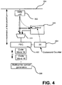
- Fig. 4 illustrates an exemplary embodiment wherein the time base is based on a sequence numbering of FEC (forward error correction) codewords.
- FEC forward error correction
- a FEC codeword generator 402 is arranged outputting every time T' a codeword.
- the data unit 302 has passed the first point 304 at the time the FEC codeword generator is processing the FEC codeword with sequence number 20 as indicated by a codeword counter 404.
- the expected delay or transfer time from the first point 304 to the FEC generator is assumed to be n'. Therefore, the time-marker information is calculated to 20+n' which is stored in the buffer 310.
- the generating of the time-marker information is initiated based on the receiving of the data unit at a sublayer which is hierarchically higher than the sublayer which provides the timebase for the time-marker information.
- Retransmission data units may be multiplexed into the process flow between the hierarchically higher sublayer and the sublayer providing the timebase.
- the delay caused by the multiplexing of the retransmitted data units does not influence the time-marker marker.
- a bonding of communication links to determine at the receiver for the data units the point in time when the data unit should be transferred to the bonding layer independently whether it is a retransmitted data unit or a first time transmitted data unit and independent of any delay introduced by the multiplexing of data units in one data link which may cause a delay of the actual transmission time for one of the link.
- a bonding entity or bonding layer may be provided to bond data links together for achieving higher transmission bandwidth.
- the bonding entity may receive the data to be transmitted and distributes data units to a first processing path associated with the first link and a second processing path associated with the second link.
- a first time-marker information is then provided for a data unit distributed to the first processing path and a second time-marker information is provided for a data unit distributed to the second processing path.
- the data units are then transmitted over the first and second link, respectively.
- a request for retransmission may be transmitted from the receiver to the transmitter for each link.
- the data unit including now the first time-marker information is retransmitted.
- the corresponding data unit including now the second time-marker information is retransmitted to the receiver.
- the time-marker information of the received retransmitted data unit is checked.
- a point in time for transferring the retransmitted data unit to a hierarchical higher sublayer for example the bonding layer is then determined based on the time-marker information and the retransmitted data unit is then transferred to the hierarchically higher sublayer based on the determined point in time.
- the point in time for transferring to the hierarchically higher sublayer may for example be calculated by using a predetermined delay between the receiver and the transmitter. The receiver adds this delay to the time-marker information in order to determine the point in time to transfer the data unit. In other embodiments, processing delays at the receiver and/or at the transmitter which may be pre-known or predetermined may be taken into account.
- Fig. 5a and 5b show one embodiment implementing a bonding of two communication links.
- a bonding entity or bonding layer 504 is implemented to distribute the data units amongst the two communication links.
- the bonding entity is implemented in this embodiment directly above a gamma interface 512 at the transmitter.
- the bonding entity 504 provides a sequence numbering for each distributed data unit which is used at a bonding entity at the receiver for assembling the data units in the same sequence.
- the sequence numbering is referred to as SID (sequence identifier).
- the sequence numbering can be used to identify lost data units at the receiver and to identify gaps by monitoring the SID.
- the missing numbers are requested for retransmission the data unit corresponding to the missing number.
- the last correctly received data unit may be indicated to the transmitter in order to request retransmission.
- the receiver may not exactly known whether retransmission should be requested or not because the received sequence numbers of first transmitted data units are mixed up with retransmitted data units.
- the time-marker information also provides an indication whether the received data unit is a retransmitted data unit or not. This allows the receiver to take for generating a retransmission request into account whether the received data units are retransmitted or first transmitted when analyzing a received sequence of data units.
- Each of the communication links stores at the receiver side the distributed data units together with the time-marker information as described above.
- the data units are then transmitted to the receiver side.
- Each receiver side has a retransmission buffer 502 to buffer the received data units and a receiver bonding entity 506.
- the receiver bonding entity is provided in this embodiment hierarchically directly above the gamma interface 514.
- the data units are transferred from the retransmission buffer to the bonding entity where they are aggregated to one data stream.
- buffers are used to buffer the data units for each link in order to compensate delay variations that are inherent in the data communication system plus a mismatch in the permanent delays between the bonded links due to unknown components of the delay.
- the buffers at the receiver bonding entity 506 may have only a small capacity for example 15 Kbits. Therefore, in order to allow the aggregating, the data units at each link are transferred to the receiver bonding entity 506 in approximately the same sequence order in which the data units have been distributed by the bonding entity 504 at the transmitter. Or in other words, the delay between the transmitter and receiver is made constant for both links independently whether the data units are received at one or both of the links for the first time, or are retransmitted or multiple time retransmitted. In case of retransmission on one link, the data unit which had to be retransmitted one or more times has a significant delay to the data unit transmitted on the other link.
- the transfer of the data units for each link at approximately the required time to the receiver bonding entity 506 independent of any delay added by retransmission can be achieved. Furthermore, the above described embodiments allow implementing the constant delay without any changes of sublayers hierarchically above the gamma layer, i.e. without any change of the bonding entity.
- the receiver can easily distinguish between first time transmitted data units and retransmitted data units and can take this into account when determining the data units which are to be retransmitted.
- Fig. 5a shows a situation when two data unit 510a and 510b which have been distributed by the transmitter bonding entity 504 at the same time are received at the receiver. While the second link receives the data unit 510b correctly, the data unit 510a at the second link is corrupted. This requires a retransmission of the data unit 510a causing additional delay as shown in Fig. 5b .
- the correctly received data unit 510b is just scheduled to be transferred to the receiver bonding entity 506 while the data unit 510a would be delayed compared to the data unit 510b because it has been retransmitted.
- the retransmitted data unit 510a contains the time-marker information, it can be identified to be transferred at the same time instant as the data unit 510b based on the calculation of a transfer point of time.
- the delay on the line can be made constant.
- the delay from bonding entity to bonding entity or from gamma interface to gamma interface can be made also constant.
- the delay from the receiving of the data unit on the link to the transferring of the data unit over the gamma interface to the bonding entity is constant or can be made constant.
- the receiver can easily calculate then correct transfer time for the retransmitted data unit based on the included time marker by using the parameters of the link-to-link delay which is assumed to be constant for both links and/or the parameters of the gamma-to-gamma delay which may also be assumed to be constant for both links.
- processing delays within the receiver and/or transmitter can be taken into account.
- Fig. 6 shows one embodiment of a DSL system implementing retransmission and bonding as described above.
- a bonding sublayer 602 is implemented above a gamma interface 604.
- Data units are provided to TPS-TC (transmission protocol specific- transmission convergence) sublayers 606 which are already implemented in existing DSL systems.
- the TPS-TC layer provides functionality such as packetizing into frames, organizing of the bearer channels, multiplexing.
- the TPS-TC sublayers 606 include a rate decoupling and a TC (Transmission convergence)-layer.
- a retransmission sublayer 608 is implemented hierarchically below the TC-sublayer.
- the retransmission sublayer may be implemented in other positions of the protocol stack for example in a PMS-TC (physical media specific - transmission convergence) layer of a TC-layer.
- PMS-TC physical media specific - transmission convergence
- the storing of the data units in the retransmission buffer 310 and the multiplexing of the retransmitted data units into the data stream by multiplexer 312 is implemented.
- PMS-TC and PMD (Physical media dependent) sublayers are shown in Fig. 6 with reference number 610. These sublayers include the FEC codeword generation and the multicarrier symbol generation which provide in embodiments the time basis for the time-marker information.
- the receiver side is connected to the transmitter side by a link 612.
- the complementary stack is implemented.
- the retransmission sublayer implements at the receiver a receive control and retransmission request generation indicated in Fig. 6 by a block 614.
- Block 614 is connected to the buffer 310 of the transmitter by a backchannel 613 for transferring retransmission requests from the receiver to the transmitter.
- the retransmission sublayer implements the retransmission buffer 502 which stores the received data units until they are transferred to the higher sublayers.
- the time-marker information may be generated in each of the sublayers above the multiplexer 312. Based on the receiving of the data unit at any of the layers, the current count number may be looked up and used for providing the time-marker information as described above.
- the retransmission functionality may in embodiments be implemented in various sublayers of the first layer (PHY layer).
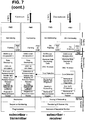
- Fig. 7 shows one embodiment wherein the retransmission functionality is implemented in a sublayer directly below the gamma interface.
- Fig. 7 shows an embodiment of a protocol stack for bonding with two links and retransmission for downstream data where queuing and forwarding of the retransmission sublayer transmitter wherein the retransmission sublayer is located directly below the distribution of the bonding sublayer transmitter.
- Fig. 7 shows a protocol stack for a receiver and transmitter which may be implemented at the Central Office (CO) site and at the subscriber site (remote site), respectively.
- the protocol stack of the CO receiver comprises a bonding layer directly above the gamma interface including fragmentation, sequence numbering and distribution of the data units.
- the retransmission sublayer is located directly below the gamma interface and includes an input buffer, rate decoupling functionality which decouples the two data links by inserting of a special type of idle fragments. Furthermore, the retransmission sublayer includes functionalities to generate and prepend the retransmission headers and a queuing and forwarding functionality.
- the rate decoupling entity fills each TPS-TC encapsulation structure (in case of 64/65-octet TPS-TC it fills each 65-byte structure) with idle bits if data fragments are not fully occupied with user data in order to decouple the data rates of the two links. If a data fragment is fully occupied with idle bits, indication can be provided to the data fragment in order to avoid unnecessary retransmission of the non-useful data.
- the CRC-16 calculation entity provides CRC-16 calculation based on packet start and packet end identification provided in some of the data fragments.
- the 64/65 octet encapsulation entity provides 64/65 octet encapsulation as is known to a person skilled in the art.
- PMS-TC Physical Medium Dependent
- each of the above described entities of the PMS-TC and TPS-TC sublayers are provided for each of the subscriber lines.
- a protocol stack having the reverse sequence of the protocol stack is provided in order to implement a receiver protocol stack. It is to be understood for a person skilled in the art that functionalities such as the interleaver framing and rate coupling are replaced at the receiver site by the complementary functionality.
- error detection is provided at the receiver protocol stack of the subscriber site to detect corrupt received data units.
- a line specific error detection is capable of identifying the corrupt data units and to request retransmission for the corrupt or missed data units.
- the sequence number information may be provided from the protocol stack for each of the subscriber lines to the OAM data entities of the transmitter protocol stacks for each subscriber line to allow transmitting of a retransmission request including the sequence number information over both subscriber lines back to the Central Office.
- error detection is not implemented at the receiver protocol stack of the Central Office since in this embodiment retransmission protection is provided only in downstream direction.
- the retransmission request is processed.
- a sublayer for demapping of the retransmission request is provided which transfers the sequence number identified for retransmission to the queuing and forwarding entity in order to start the retransmitting of the data units which are identified as corruptly received.
- the layer model shown in Fig. 7 is only one of many examples of implementing retransmission as described above in a layer model. Therefore, other embodiments provide other layer models for implementing the retransmission at other sublayers, for example at the PMS-TC layer.
- Fig. 7 shows one embodiment with a PMS-TC layer for Ethernet packets
- other layer models may use a PMS-TC layer for ATM cells.
- some modification may be provided.
- the basic retransmission unit may be a fragment of the Ethernet packet or a plurality of fragments
- the basic retransmission unit may be an ATM cell or a plurality of ATM cells.
- circuit or circuitry used herein are to be interpreted in a sense not only including hardware but also software, firmware or any combinations thereof.
- data may be interpreted to include any form of representation such as an analog signal representation, a digital signal representation, a modulation onto carrier signals etc.
- coupled or “connected” may be interpreted in a broad sense not only covering direct but also indirect coupling.
- entity may in embodiments include any device, apparatus, circuit, hardware, software, software modules, firmware, firmware modules, chips or other semiconductors as well as logical units or physical implementations of protocol layers as well as parts of same.
- two or more entities may in embodiments be implemented in a single device, single apparatus, single circuit, single hardware, single software, single software modules, single firmware, single firmware modules, single chip as well as single logical units or physical implementations of protocol layers.
Landscapes
- Engineering & Computer Science (AREA)
- Computer Networks & Wireless Communication (AREA)
- Signal Processing (AREA)
- Detection And Prevention Of Errors In Transmission (AREA)
- Communication Control (AREA)
Applications Claiming Priority (3)
| Application Number | Priority Date | Filing Date | Title |
|---|---|---|---|
| US8802108P | 2008-08-12 | 2008-08-12 | |
| US12/500,592 US9450713B2 (en) | 2008-08-12 | 2009-07-09 | Retransmitting data with time-marker information |
| EP09009887.2A EP2154807B1 (fr) | 2008-08-12 | 2009-07-30 | Procédé de retransmission DSL et dispositif correspondant |
Related Parent Applications (2)
| Application Number | Title | Priority Date | Filing Date |
|---|---|---|---|
| EP09009887.2A Division EP2154807B1 (fr) | 2008-08-12 | 2009-07-30 | Procédé de retransmission DSL et dispositif correspondant |
| EP09009887.2A Division-Into EP2154807B1 (fr) | 2008-08-12 | 2009-07-30 | Procédé de retransmission DSL et dispositif correspondant |
Publications (1)
| Publication Number | Publication Date |
|---|---|
| EP3252982A1 true EP3252982A1 (fr) | 2017-12-06 |
Family
ID=41211674
Family Applications (3)
| Application Number | Title | Priority Date | Filing Date |
|---|---|---|---|
| EP17175734.7A Ceased EP3252982A1 (fr) | 2008-08-12 | 2009-07-30 | Dispositifs de retransmission dsl |
| EP17169942.4A Ceased EP3244564A1 (fr) | 2008-08-12 | 2009-07-30 | Dispositifs de retransmission dsl |
| EP09009887.2A Active EP2154807B1 (fr) | 2008-08-12 | 2009-07-30 | Procédé de retransmission DSL et dispositif correspondant |
Family Applications After (2)
| Application Number | Title | Priority Date | Filing Date |
|---|---|---|---|
| EP17169942.4A Ceased EP3244564A1 (fr) | 2008-08-12 | 2009-07-30 | Dispositifs de retransmission dsl |
| EP09009887.2A Active EP2154807B1 (fr) | 2008-08-12 | 2009-07-30 | Procédé de retransmission DSL et dispositif correspondant |
Country Status (3)
| Country | Link |
|---|---|
| US (1) | US9450713B2 (fr) |
| EP (3) | EP3252982A1 (fr) |
| CN (1) | CN101707518B (fr) |
Families Citing this family (9)
| Publication number | Priority date | Publication date | Assignee | Title |
|---|---|---|---|---|
| US8553721B2 (en) * | 2008-08-22 | 2013-10-08 | Lantiq Deutschland Gmbh | Channel bonding and packet fragment retransmission method and apparatus |
| US8910006B2 (en) * | 2008-09-12 | 2014-12-09 | Infineon Technologies Ag | Systems and methods for regulating delay between network interfaces |
| US8918675B2 (en) * | 2011-12-19 | 2014-12-23 | Microsoft Corporation | Rectifying corrupt sequence values in distributed systems |
| US9596177B2 (en) * | 2012-04-12 | 2017-03-14 | Lantiq Deutschland Gmbh | Method for a retransmission roundtrip correction |
| US9647692B2 (en) * | 2014-01-24 | 2017-05-09 | Avago Technologies General Ip (Singapore) Pte. Ltd. | Upstream forward error correction codeword filling |
| US9432144B2 (en) * | 2014-09-12 | 2016-08-30 | Ciena Corporation | Precision time transfer systems and methods in optical networks |
| CN111800225A (zh) * | 2016-12-09 | 2020-10-20 | 华为技术有限公司 | 一种数据传输方法及设备 |
| US10594395B2 (en) | 2018-07-23 | 2020-03-17 | Ciena Corporation | Systems and methods for compensating coherent optics delay asymmetry in a packet optical network |
| US11552722B2 (en) | 2020-12-10 | 2023-01-10 | Ciena Corporation | Precision time protocol using a coherent optical DSP frame |
Citations (2)
| Publication number | Priority date | Publication date | Assignee | Title |
|---|---|---|---|---|
| US20050286424A1 (en) * | 2004-06-14 | 2005-12-29 | Broadcom Corporation | Differential delay compensation and measurement in bonded systems |
| US20080063007A1 (en) * | 2006-09-13 | 2008-03-13 | Broadcom Corporation | System for Communicating Data in xDSL Using Data Retransmission |
Family Cites Families (13)
| Publication number | Priority date | Publication date | Assignee | Title |
|---|---|---|---|---|
| US20020194343A1 (en) * | 2001-02-28 | 2002-12-19 | Kishan Shenoi | Measurement of time-delay, time-delay-variation, and cell transfer rate in ATM networks |
| US6490296B2 (en) * | 2001-02-28 | 2002-12-03 | Symmetricom, Inc. | Multi-link segmentation and reassembly for bonding multiple PVC's in an inverse multiplexing arrangement |
| EP1791285A1 (fr) * | 2005-11-29 | 2007-05-30 | Alcatel Lucent | Dispositif d'ARQ hybride et procédé correspondant, où la FEC redondance est adaptée basé sur le nombre de retransmissions d'un paquet |
| EP2173071B1 (fr) * | 2006-04-12 | 2013-06-26 | TQ Delta, LLC | Retransmission de paquet et partage de mémoire |
| WO2007146048A2 (fr) * | 2006-06-06 | 2007-12-21 | Adaptive Spectrum And Signal Alignment, Inc. | Système dsl |
| US7970733B2 (en) * | 2006-09-13 | 2011-06-28 | Broadcom Corporation | Method for communicating data in xDSL using data retransmission |
| US8320248B2 (en) | 2006-09-13 | 2012-11-27 | Broadcom Corporation | Method and system for communicating data in xDSL using data retransmission |
| EP1944902B1 (fr) * | 2007-01-10 | 2012-11-21 | Alcatel Lucent | Procédé de surveillance des bruits d'impulsion, terminal de réseau associé, noeud de réseau et gestionnaire de réseau |
| US8351464B2 (en) * | 2007-10-02 | 2013-01-08 | Infineon Technologies Ag | Retransmission in data communication systems |
| WO2009089152A1 (fr) * | 2008-01-03 | 2009-07-16 | Conexant Systems, Inc. | Protection cognitive et universelle contre les bruits impulsifs |
| US8125907B2 (en) * | 2008-06-12 | 2012-02-28 | Talari Networks Incorporated | Flow-based adaptive private network with multiple WAN-paths |
| US9312989B2 (en) * | 2008-07-07 | 2016-04-12 | Cisco Technology, Inc. | Importance-based FEC-aware error-repair scheduling |
| US8910006B2 (en) * | 2008-09-12 | 2014-12-09 | Infineon Technologies Ag | Systems and methods for regulating delay between network interfaces |
-
2009
- 2009-07-09 US US12/500,592 patent/US9450713B2/en active Active
- 2009-07-30 EP EP17175734.7A patent/EP3252982A1/fr not_active Ceased
- 2009-07-30 EP EP17169942.4A patent/EP3244564A1/fr not_active Ceased
- 2009-07-30 EP EP09009887.2A patent/EP2154807B1/fr active Active
- 2009-08-12 CN CN2009101664988A patent/CN101707518B/zh active Active
Patent Citations (2)
| Publication number | Priority date | Publication date | Assignee | Title |
|---|---|---|---|---|
| US20050286424A1 (en) * | 2004-06-14 | 2005-12-29 | Broadcom Corporation | Differential delay compensation and measurement in bonded systems |
| US20080063007A1 (en) * | 2006-09-13 | 2008-03-13 | Broadcom Corporation | System for Communicating Data in xDSL Using Data Retransmission |
Non-Patent Citations (1)
| Title |
|---|
| "Retransmission at gamma interface for PTM;BF-xyz", ITU-T DRAFT ; STUDY PERIOD 2005-2008, INTERNATIONAL TELECOMMUNICATION UNION, GENEVA ; CH, vol. 4/15, 28 November 2007 (2007-11-28), pages 1 - 5, XP017530809 * |
Also Published As
| Publication number | Publication date |
|---|---|
| EP2154807A2 (fr) | 2010-02-17 |
| CN101707518A (zh) | 2010-05-12 |
| EP2154807B1 (fr) | 2019-01-30 |
| US20100042883A1 (en) | 2010-02-18 |
| US9450713B2 (en) | 2016-09-20 |
| CN101707518B (zh) | 2013-09-18 |
| EP2154807A3 (fr) | 2014-01-08 |
| EP3244564A1 (fr) | 2017-11-15 |
Similar Documents
| Publication | Publication Date | Title |
|---|---|---|
| EP2154807B1 (fr) | Procédé de retransmission DSL et dispositif correspondant | |
| US8713393B2 (en) | Retransmission and retransmission request in data communication systems | |
| US11271682B2 (en) | Method and device for retransmission | |
| US8848740B2 (en) | Retransmission in data communication systems | |
| US8838525B2 (en) | Method for communicating data in xDSL using data retransmission | |
| EP2045951A2 (fr) | Schéma de retransmission pour systèmes de communications | |
| US8468427B2 (en) | Retransmission scheme for communication systems | |
| US20140050105A1 (en) | Traffic-Adaptive Repeated Transmission | |
| US8503487B2 (en) | Communication methods and apparatuses |
Legal Events
| Date | Code | Title | Description |
|---|---|---|---|
| PUAI | Public reference made under article 153(3) epc to a published international application that has entered the european phase |
Free format text: ORIGINAL CODE: 0009012 |
|
| AC | Divisional application: reference to earlier application |
Ref document number: 2154807 Country of ref document: EP Kind code of ref document: P |
|
| AK | Designated contracting states |
Kind code of ref document: A1 Designated state(s): AT BE BG CH CY CZ DE DK EE ES FI FR GB GR HR HU IE IS IT LI LT LU LV MC MK MT NL NO PL PT RO SE SI SK SM TR |
|
| 17P | Request for examination filed |
Effective date: 20180606 |
|
| RBV | Designated contracting states (corrected) |
Designated state(s): AT BE BG CH CY CZ DE DK EE ES FI FR GB GR HR HU IE IS IT LI LT LU LV MC MK MT NL NO PL PT RO SE SI SK SM TR |
|
| 17Q | First examination report despatched |
Effective date: 20190325 |
|
| STAA | Information on the status of an ep patent application or granted ep patent |
Free format text: STATUS: EXAMINATION IS IN PROGRESS |
|
| STAA | Information on the status of an ep patent application or granted ep patent |
Free format text: STATUS: THE APPLICATION HAS BEEN REFUSED |
|
| 18R | Application refused |
Effective date: 20201001 |