EP3252913A1 - System for electrical charging of shopping carts equipped with electrical devices - Google Patents
System for electrical charging of shopping carts equipped with electrical devices Download PDFInfo
- Publication number
- EP3252913A1 EP3252913A1 EP16172355.6A EP16172355A EP3252913A1 EP 3252913 A1 EP3252913 A1 EP 3252913A1 EP 16172355 A EP16172355 A EP 16172355A EP 3252913 A1 EP3252913 A1 EP 3252913A1
- Authority
- EP
- European Patent Office
- Prior art keywords
- conductor
- charging
- electrical
- shopping cart
- spring
- Prior art date
- Legal status (The legal status is an assumption and is not a legal conclusion. Google has not performed a legal analysis and makes no representation as to the accuracy of the status listed.)
- Granted
Links
Images


Classifications
-
- H—ELECTRICITY
- H02—GENERATION; CONVERSION OR DISTRIBUTION OF ELECTRIC POWER
- H02J—CIRCUIT ARRANGEMENTS OR SYSTEMS FOR SUPPLYING OR DISTRIBUTING ELECTRIC POWER; SYSTEMS FOR STORING ELECTRIC ENERGY
- H02J7/00—Circuit arrangements for charging or depolarising batteries or for supplying loads from batteries
- H02J7/0042—Circuit arrangements for charging or depolarising batteries or for supplying loads from batteries characterised by the mechanical construction
-
- B—PERFORMING OPERATIONS; TRANSPORTING
- B62—LAND VEHICLES FOR TRAVELLING OTHERWISE THAN ON RAILS
- B62B—HAND-PROPELLED VEHICLES, e.g. HAND CARTS OR PERAMBULATORS; SLEDGES
- B62B3/00—Hand carts having more than one axis carrying transport wheels; Steering devices therefor; Equipment therefor
- B62B3/14—Hand carts having more than one axis carrying transport wheels; Steering devices therefor; Equipment therefor characterised by provisions for nesting or stacking, e.g. shopping trolleys
-
- B—PERFORMING OPERATIONS; TRANSPORTING
- B62—LAND VEHICLES FOR TRAVELLING OTHERWISE THAN ON RAILS
- B62B—HAND-PROPELLED VEHICLES, e.g. HAND CARTS OR PERAMBULATORS; SLEDGES
- B62B5/00—Accessories or details specially adapted for hand carts
-
- H—ELECTRICITY
- H02—GENERATION; CONVERSION OR DISTRIBUTION OF ELECTRIC POWER
- H02J—CIRCUIT ARRANGEMENTS OR SYSTEMS FOR SUPPLYING OR DISTRIBUTING ELECTRIC POWER; SYSTEMS FOR STORING ELECTRIC ENERGY
- H02J7/00—Circuit arrangements for charging or depolarising batteries or for supplying loads from batteries
- H02J7/0042—Circuit arrangements for charging or depolarising batteries or for supplying loads from batteries characterised by the mechanical construction
- H02J7/0045—Circuit arrangements for charging or depolarising batteries or for supplying loads from batteries characterised by the mechanical construction concerning the insertion or the connection of the batteries
-
- B—PERFORMING OPERATIONS; TRANSPORTING
- B62—LAND VEHICLES FOR TRAVELLING OTHERWISE THAN ON RAILS
- B62B—HAND-PROPELLED VEHICLES, e.g. HAND CARTS OR PERAMBULATORS; SLEDGES
- B62B2501/00—Manufacturing; Constructional features
-
- B—PERFORMING OPERATIONS; TRANSPORTING
- B62—LAND VEHICLES FOR TRAVELLING OTHERWISE THAN ON RAILS
- B62B—HAND-PROPELLED VEHICLES, e.g. HAND CARTS OR PERAMBULATORS; SLEDGES
- B62B3/00—Hand carts having more than one axis carrying transport wheels; Steering devices therefor; Equipment therefor
- B62B3/14—Hand carts having more than one axis carrying transport wheels; Steering devices therefor; Equipment therefor characterised by provisions for nesting or stacking, e.g. shopping trolleys
- B62B3/1408—Display devices mounted on it, e.g. advertisement displays
- B62B3/1424—Electronic display devices
-
- B—PERFORMING OPERATIONS; TRANSPORTING
- B62—LAND VEHICLES FOR TRAVELLING OTHERWISE THAN ON RAILS
- B62B—HAND-PROPELLED VEHICLES, e.g. HAND CARTS OR PERAMBULATORS; SLEDGES
- B62B3/00—Hand carts having more than one axis carrying transport wheels; Steering devices therefor; Equipment therefor
- B62B3/14—Hand carts having more than one axis carrying transport wheels; Steering devices therefor; Equipment therefor characterised by provisions for nesting or stacking, e.g. shopping trolleys
- B62B3/1428—Adaptations for calculators, memory aids or reading aids
-
- Y—GENERAL TAGGING OF NEW TECHNOLOGICAL DEVELOPMENTS; GENERAL TAGGING OF CROSS-SECTIONAL TECHNOLOGIES SPANNING OVER SEVERAL SECTIONS OF THE IPC; TECHNICAL SUBJECTS COVERED BY FORMER USPC CROSS-REFERENCE ART COLLECTIONS [XRACs] AND DIGESTS
- Y02—TECHNOLOGIES OR APPLICATIONS FOR MITIGATION OR ADAPTATION AGAINST CLIMATE CHANGE
- Y02T—CLIMATE CHANGE MITIGATION TECHNOLOGIES RELATED TO TRANSPORTATION
- Y02T10/00—Road transport of goods or passengers
- Y02T10/60—Other road transportation technologies with climate change mitigation effect
- Y02T10/70—Energy storage systems for electromobility, e.g. batteries
-
- Y—GENERAL TAGGING OF NEW TECHNOLOGICAL DEVELOPMENTS; GENERAL TAGGING OF CROSS-SECTIONAL TECHNOLOGIES SPANNING OVER SEVERAL SECTIONS OF THE IPC; TECHNICAL SUBJECTS COVERED BY FORMER USPC CROSS-REFERENCE ART COLLECTIONS [XRACs] AND DIGESTS
- Y02—TECHNOLOGIES OR APPLICATIONS FOR MITIGATION OR ADAPTATION AGAINST CLIMATE CHANGE
- Y02T—CLIMATE CHANGE MITIGATION TECHNOLOGIES RELATED TO TRANSPORTATION
- Y02T10/00—Road transport of goods or passengers
- Y02T10/60—Other road transportation technologies with climate change mitigation effect
- Y02T10/7072—Electromobility specific charging systems or methods for batteries, ultracapacitors, supercapacitors or double-layer capacitors
Definitions
- the present disclosure relates generally to charging smart shopping carts, and more specifically, to a system for electrical charging of shopping carts equipped with electrical devices.
- a smart shopping cart has one or more electric devices integrated with the shopping cart.
- the one or more electric devices can be used for tracking the location of the cart, automated billing, etc.
- Such an electric device may include a barcode scanner, a weight sensor, a location sensor etc.
- the barcode scanner may scan barcodes of items placed in the shopping cart.
- the smart shopping cart may also include a display that shows the total price of items placed, thus making it easy for shoppers to budget their shopping. It may also compare the items placed in the smart shopping cart with a user's shopping list, and tick items off the list once placed.
- An integrated battery typically powers the one or more electric devices.
- a major problem with such existing smart shopping carts lies with transferring electricity to charge the integrated battery used to power the electric devices.
- Wired chargers used to charge the integrated battery cause a substantial amount of friction, and wear and tear. Therefore, in light of the foregoing discussion, there exists a need to overcome the aforementioned drawbacks in existing approaches for charging a battery used to power the electric devices in a smart shopping cart, due to friction.
- the present disclosure seeks to provide a system for electrical charging of shopping carts equipped with electrical devices.
- an embodiment of the present disclosure provides a system for electrical charging of shopping carts equipped with electrical devices.
- the system comprises (a) an electrical charging station comprising a charging profile made of an electrically insulating material and a charging element made of an electrically conducting material, wherein the charging profile is arranged to partially cover the charging element, and (b) at least one shopping cart comprising an electrical device and a conductor arrangement electrically connected to the electrical device, wherein the conductor arrangement comprises (i) a casing comprising a first part comprising an opening and a second part arranged to be in contact with the shopping cart, and (ii) a conductor spring, a spring support and a conductor arranged inside the casing, wherein the conductor spring and the conductor are arranged in electrical contact with each other, and wherein the conductor is arranged to be in contact with the charging element of the electrical charging station through the opening of the first part of the casing, and the conductor spring is arranged to allow movement of the conductor inside the casing.
- Embodiments of the present disclosure substantially eliminate or at least partially address the aforementioned problems in the prior art, and enable wireless charging of one or more electric devices associated with a smart shopping cart with minimum friction.
- an underlined number is employed to represent an item over which the underlined number is positioned or an item to which the underlined number is adjacent.
- a non-underlined number relates to an item identified by a line linking the non-underlined number to the item. When a number is non-underlined and accompanied by an associated arrow, the non-underlined number is used to identify a general item at which the arrow is pointing.
- the system comprises an electrical charging station comprising a charging profile made of an electrically insulating material and a charging element made of an electrically conducting material.
- the charging station can be arranged in connection with a storage station of the shopping carts, and it typically has a self-standing structure made for example from metallic tubes.
- the charging profile is arranged to partially cover the charging element for electrical insulation.
- the system also comprises at least one shopping cart comprising an electrical device and a conductor arrangement electrically connected to the electrical device.
- the electrical device can be any electrical device used in connection with shopping carts, such as a bar code scanner, a display connected to an information system of the shop etc.
- the conductor arrangement is electrically connected to the electrical device, i.e. it allows electricity from the charging station to be transferred to the electrical device for charging it.
- the conductor arrangement comprises a casing that comprises a first part comprising an opening and a second part arranged to be in contact with the shopping cart.
- the conductor arrangement also comprises a conductor spring, a spring support and a conductor arranged inside the casing, wherein the conductor spring and the conductor are arranged in electrical contact with each other, to allow transfer of electricity.
- the conductor is arranged to be in contact with the charging element of the electrical charging station through the opening of the first part of the casing, i.e. in electrical contact with it, and the conductor spring is arranged to allow movement of the conductor inside the casing.
- the present disclosure thus provides a system that reduces friction between the electrical charging station and the conductor attached to the shopping cart and provides wireless charging solution to the shopping carts. As friction is reduced, the wear and tear is also reduced.
- the conductor spring acts both as a spring and a conducting element, thus compensating the positioning of the shopping cart in the electrical charging station, the possible misalignment of the electrical charging station, and the wear of wheels of the shopping cart.
- the charging profile is an insulator, so that the charging profile does not conduct electricity to the structure of the electrical charging station.
- the conductor comprises a cylindrical part and a bearing that allows movement of the cylindrical part.
- the conductor is preferably made of an electrically conductive material, such as metal. It is also possible to make it from an insulating material, provided that it can still be in electrical contact with the conductor spring and the electrical device, to transfer electricity from the loading system to the electrical device of the shopping cart.
- the conductor spring is arranged to allow the conductor to move towards and away from the charging element. This movement allows for the system to work even when the shopping cart is slightly misaligned and if the parts of the system are slightly worn out.
- the conductor arrangement is arranged in a handle of the shopping cart.
- the conductor arrangement may also be arranged at another position of the shopping cart, such as the wheel or wheels or the base of the shopping cart.
- the handle is however preferred, as it is far away from ground (i.e. further away from dust, rocks and snow, for example), and it is also believed that it is easier for the user to position the shopping cart into a storage station comprising the electrical charging system, when the alignment is made using the handle.
- the electrical charging station is arranged in a storage station of the shopping carts.
- the conductor arrangement is electrically connected to the electrical device. According to an embodiment, this is achieved with the conductor arrangement further comprising a crimp connector connecting the conductor spring with an electrical wire for transferring electricity to the electrical device.
- the electrical wires are preferably arranged inside the casing of the conductor arrangement, and suitably covered between the conductor arrangement and the electrical device.
- the charging element is made of metal.
- the charging element can be made of copper, aluminium or stainless steel.
- the charging profile is made of an insulating plastic material.
- the plastic material may be any suitable material, such as polyethylene, polypropylene, polyamide etc.
- the charging profile could also be made of another type of material, such as wood, if desired.
- each shopping cart comprises a first conductor arrangement comprises a first polarity and a second conductor arrangement comprises a second polarity that is opposite to the first polarity.
- the conductor arrangements are arranged at opposing sides of the handle of the shopping cart. This embodiment allows the system to work also with shopping carts not comprising metallic wheels that are in contact with the ground.
- the two conductor arrangements can also be placed in such a manner that one is arranged in the handle and the other in another part of the shopping cart, as discussed above.
- the electrical path between the two conductor arrangements is of course insulated such that the user cannot get electric shocks.
- the conductor arrangement on a left side of the shopping cart comprises a positive polarity and the conductor arrangement on a right side of the shopping cart comprises a negative polarity.
- the charging profile is attachable by attachment means and the charging element is attachable to the charging profile via the form of the charging profile.
- the attachment means can be any suitable mans, such as screws, rivets, nails or glue.
- the charging profile has a form that allows the charging element to be sled into it, such as a C-profile. This allows for the charging profile to have a smooth surface, which further reduces friction when the shopping carts are positioned in the charging system and removed from it.
- the electrical charging station further comprises a guide element arranged to lock the charging element into place.
- the guide element is typically placed at the extremity of the charging element, and can be attached by any suitable means. Its function is to lock the charging element into place, especially when the charging element is attached only via the form of the charging profile, and to help guide the shopping carts into the system.
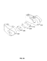
- FIG. 1 is an exemplary view of a system for electrical charging of a shopping cart 100 that is equipped with an electrical device that includes at least one electrical charging station 102 and a conductor arrangement 104 electrically connected to the electrical device, in accordance with an embodiment of the present disclosure.
- the electrical charging station 102 may be arranged in a storage station of the shopping cart 100.
- the storage station includes a plurality of tubular structures 106.
- the electrical charging station 102 includes a charging profile 108 made of an electrically insulating material (e.g., plastic) and a charging element 110 made of an electrically conducting material (e.g., copper).
- the electrical charging station 102 (e.g., charging rail) is attached to the plurality of tubular structures 106.
- the conductor arrangement 104 may be attached to a handle 112 of the shopping cart 100, one on each end.
- FIG. 2A is an exploded view of the conductor arrangement 104 of FIG. 1 , in accordance with an embodiment of the present disclosure.
- the conductor arrangement 104 comprises a casing that includes a first part 202 and a second part 204, a conductor 206, a conductor spring 208, and a spring support 210.
- the first part 202 and the second part 204 of the casing enclose all the components of the conductor arrangement 104.
- the second part 204 of the casing is arranged to be in contact with the handle 112 of the shopping cart 100.
- the conductor 206 is arranged to be in contact with the charging element 110 of the electrical charging station 102 through an opening of the first part 202 of the casing.
- the conductor spring 208 is arranged to be in electrical contact with the conductor 206.
- the spring support 210 provides support to the conductor spring 208 inside the casing.
- FIG. 2B is a sectional view of the conductor arrangement 104 of FIG. 1 , in accordance with an embodiment of the present disclosure.
- the conductor 206 comprises a cylindrical part and a bearing that allows movement of the cylindrical part of the conductor 206.
- the conductor 206 and the conductor spring 208 transfer the electricity from the electrical charging station 102 to the electrical device.
- FIG. 3 is a schematic illustration of a crimp connector 302 that is connected to the conductor spring 208 in the conductor arrangement 104 of FIG. 1 , in accordance with an embodiment of the present disclosure.
- the crimp connector 302 connects a wire inside the second part 204 of the casing that is arranged to be in contact with the shopping cart 100 with the conductor spring 208.
- the crimp connector 302 transfers electricity from the conductor spring 208 to the wire inside the second part 204 of the casing.
- FIG.4 is a schematic illustration of the parts of the electrical charging station 102 that is connected to the tubular structures 106 in the electrical charging station 102 of FIG. 1 , in accordance with an embodiment of the present disclosure.
- the electrical charging station 102 includes a guide element 402 that is attached to the tubular structures 106.
- the guide element 402 is arranged to lock the charging element 110 within the charging profile 108.
- the charging profile 108 is attached to the tubular structures 106 by attachment means (e.g. one or more rivets) and the charging element 110 is attached to the charging profile 108 by the form of the charging profile 108.
- FIG. 5 is a schematic illustration of the conductor 206 in the conductor arrangement 104 connected to the charging element 110 of the electrical charging station 102 of FIG. 1 , in accordance with an embodiment of the present disclosure.
- the conductor 206 is arranged to be in contact with the charging element 110 of the electrical charging station 102 that allows the charging of the electrical device that is mounted on the shopping cart 100 or on a part of it.
- the conductor spring 208 inside the casing is arranged to allow movement of the conductor 206 towards and away from the charging element 110 of the electrical charging station 102.
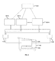
- FIG. 6 is a schematic electrical diagram of the electrical charging station 102 that is adapted to conduct electrical power to charge the electrical devices that are mounted on the shopping cart 100 of FIG. 1 , in accordance with an embodiment of the present disclosure.
- the schematic electrical diagram of the electrical loading station 102 comprises a power source 602, a plurality of AC to DC converters 604A-N, a step down transformer 606 and an electrical device 608.
- the plurality of AC to DC converters 604A-N receive 230V AC power from the power source 602.
- the plurality of AC to DC converters 604A-N convert 230V AC power to 12V DC and transmit to the electrical charging station 102.
- the charging element 110 of the electrical charging station 102 receives 12V DC from the plurality of AC to DC converters 604A-N, and conducts 12V DC power in the charging element 110.
- the charging element 110 comprises a positive charging element 110A on a left side of the electrical charging station 102 to conduct a positive charge, and a negative charging element 110B on a right side of the electrical charging station 102 to conduct a negative charge.
- the step down transformer 606 is arranged to be in contact with the positive charging element 110A and the negative charging element 110B.
- the step down transformer 606 receives 12V DC power from the positive charging element 110A and the negative charging element 110B and converts 12V DC to 5V DC to charge the electrical device 608.
- the electrical device 608 is coupled with the step down transformer 606 for charging means.
Landscapes
- Engineering & Computer Science (AREA)
- Power Engineering (AREA)
- Chemical & Material Sciences (AREA)
- Combustion & Propulsion (AREA)
- Transportation (AREA)
- Mechanical Engineering (AREA)
- Handcart (AREA)
- Charge And Discharge Circuits For Batteries Or The Like (AREA)
Abstract
Description
- The present disclosure relates generally to charging smart shopping carts, and more specifically, to a system for electrical charging of shopping carts equipped with electrical devices.
- In a retail store or grocery store, shoppers typically push a shopping cart through aisles while selecting items of merchandise as per their shopping lists. When the shoppers finish with selecting and placing items in the shopping car as per their shopping lists, they proceed to a cash register/data terminal in a check-out area of the store to make the payment. Retailers continuously struggle to efficiently allocate human resources and available computing power to perform operational and point-of-sale tasks. Traditionally, such tasks are resource intensive and they entail significant expenditures of time and money at each retail outlet. To address this problem of retailers and to also make the experience simpler for shoppers, smart shopping carts have been introduced at retail stores.
- A smart shopping cart has one or more electric devices integrated with the shopping cart. The one or more electric devices can be used for tracking the location of the cart, automated billing, etc. Such an electric device may include a barcode scanner, a weight sensor, a location sensor etc. The barcode scanner may scan barcodes of items placed in the shopping cart. The smart shopping cart may also include a display that shows the total price of items placed, thus making it easy for shoppers to budget their shopping. It may also compare the items placed in the smart shopping cart with a user's shopping list, and tick items off the list once placed. An integrated battery typically powers the one or more electric devices. A major problem with such existing smart shopping carts lies with transferring electricity to charge the integrated battery used to power the electric devices. Wired chargers used to charge the integrated battery cause a substantial amount of friction, and wear and tear. Therefore, in light of the foregoing discussion, there exists a need to overcome the aforementioned drawbacks in existing approaches for charging a battery used to power the electric devices in a smart shopping cart, due to friction.
- The present disclosure seeks to provide a system for electrical charging of shopping carts equipped with electrical devices.
- In one aspect, an embodiment of the present disclosure provides a system for electrical charging of shopping carts equipped with electrical devices. The system comprises (a) an electrical charging station comprising a charging profile made of an electrically insulating material and a charging element made of an electrically conducting material, wherein the charging profile is arranged to partially cover the charging element, and (b) at least one shopping cart comprising an electrical device and a conductor arrangement electrically connected to the electrical device, wherein the conductor arrangement comprises (i) a casing comprising a first part comprising an opening and a second part arranged to be in contact with the shopping cart, and (ii) a conductor spring, a spring support and a conductor arranged inside the casing, wherein the conductor spring and the conductor are arranged in electrical contact with each other, and wherein the conductor is arranged to be in contact with the charging element of the electrical charging station through the opening of the first part of the casing, and the conductor spring is arranged to allow movement of the conductor inside the casing.
- Embodiments of the present disclosure substantially eliminate or at least partially address the aforementioned problems in the prior art, and enable wireless charging of one or more electric devices associated with a smart shopping cart with minimum friction.
- Additional aspects, advantages, features and objects of the present disclosure are made apparent from the drawings and the detailed description of the illustrative embodiments construed in conjunction with the appended claims that follow.
- It will be appreciated that features of the present disclosure are susceptible to being combined in various combinations without departing from the scope of the present disclosure as defined by the appended claims.
- The summary above, as well as the following detailed description of illustrative embodiments, is better understood when read in conjunction with the appended drawings. For the purpose of illustrating the present disclosure, exemplary constructions of the disclosure are shown in the drawings. However, the present disclosure is not limited to specific methods and instrumentalities disclosed herein. Moreover, those in the art will understand that the drawings are not to scale. Wherever possible, like elements have been indicated by identical numbers.
- Embodiments of the present disclosure will now be described, by way of example only, with reference to the following diagrams wherein:
-
FIG. 1 is an exemplary view of a system for electrical charging of a shopping cart that is equipped with an electrical device that includes an electrical charging station and a conductor arrangement electrically connected to the electrical device, in accordance with an embodiment of the present disclosure; -
FIG. 2A is an exploded view of the conductor arrangement ofFIG. 1 , in accordance with an embodiment of the present disclosure; -
FIG. 2B is a sectional view of the conductor arrangement ofFIG. 1 , in accordance with an embodiment of the present disclosure; -
FIG. 3 is a schematic illustration of a crimp connector that is connected to a conductor spring in the conductor arrangement ofFIG. 1 , in accordance with an embodiment of the present disclosure; -
FIG.4 is a schematic illustration of the parts of the electrical charging station that is connected to tubular structures in the electrical charging station ofFIG. 1 , in accordance with an embodiment of the present disclosure; -
FIG. 5 is a schematic illustration of a conductor in the conductor arrangement connected to a charging element of the electrical charging station ofFIG. 1 , in accordance with an embodiment of the present disclosure; and -
FIG. 6 is a schematic electrical diagram of the electrical charging station that is adapted to conduct electrical power to charge the electrical devices that are mounted on the shopping cart ofFIG. 1 , in accordance with an embodiment of the present disclosure. - In the accompanying drawings, an underlined number is employed to represent an item over which the underlined number is positioned or an item to which the underlined number is adjacent. A non-underlined number relates to an item identified by a line linking the non-underlined number to the item. When a number is non-underlined and accompanied by an associated arrow, the non-underlined number is used to identify a general item at which the arrow is pointing.
- The following detailed description illustrates embodiments of the present disclosure and ways in which they can be implemented. Although some modes of carrying out the present disclosure have been disclosed, those skilled in the art would recognize that other embodiments for carrying out or practicing the present disclosure are also possible.
- The system comprises an electrical charging station comprising a charging profile made of an electrically insulating material and a charging element made of an electrically conducting material. As will be discussed below, the charging station can be arranged in connection with a storage station of the shopping carts, and it typically has a self-standing structure made for example from metallic tubes. The charging profile is arranged to partially cover the charging element for electrical insulation.
- The system also comprises at least one shopping cart comprising an electrical device and a conductor arrangement electrically connected to the electrical device. The electrical device can be any electrical device used in connection with shopping carts, such as a bar code scanner, a display connected to an information system of the shop etc. The conductor arrangement is electrically connected to the electrical device, i.e. it allows electricity from the charging station to be transferred to the electrical device for charging it.
- The conductor arrangement comprises a casing that comprises a first part comprising an opening and a second part arranged to be in contact with the shopping cart. The conductor arrangement also comprises a conductor spring, a spring support and a conductor arranged inside the casing, wherein the conductor spring and the conductor are arranged in electrical contact with each other, to allow transfer of electricity. Indeed, the conductor is arranged to be in contact with the charging element of the electrical charging station through the opening of the first part of the casing, i.e. in electrical contact with it, and the conductor spring is arranged to allow movement of the conductor inside the casing.
- The present disclosure thus provides a system that reduces friction between the electrical charging station and the conductor attached to the shopping cart and provides wireless charging solution to the shopping carts. As friction is reduced, the wear and tear is also reduced. Indeed, the conductor spring acts both as a spring and a conducting element, thus compensating the positioning of the shopping cart in the electrical charging station, the possible misalignment of the electrical charging station, and the wear of wheels of the shopping cart. In the system, the charging profile is an insulator, so that the charging profile does not conduct electricity to the structure of the electrical charging station.
- According to one embodiment, the conductor comprises a cylindrical part and a bearing that allows movement of the cylindrical part. The conductor is preferably made of an electrically conductive material, such as metal. It is also possible to make it from an insulating material, provided that it can still be in electrical contact with the conductor spring and the electrical device, to transfer electricity from the loading system to the electrical device of the shopping cart.
- According to another embodiment, the conductor spring is arranged to allow the conductor to move towards and away from the charging element. This movement allows for the system to work even when the shopping cart is slightly misaligned and if the parts of the system are slightly worn out.
- According to another embodiment, the conductor arrangement is arranged in a handle of the shopping cart. The conductor arrangement may also be arranged at another position of the shopping cart, such as the wheel or wheels or the base of the shopping cart. The handle is however preferred, as it is far away from ground (i.e. further away from dust, rocks and snow, for example), and it is also believed that it is easier for the user to position the shopping cart into a storage station comprising the electrical charging system, when the alignment is made using the handle. Indeed, according to an embodiment, the electrical charging station is arranged in a storage station of the shopping carts. Such a combination has the advantage that the shopping carts are typically automatically returned to the charging station and hence no additional steps are needed from the shop personnel.
- The conductor arrangement is electrically connected to the electrical device. According to an embodiment, this is achieved with the conductor arrangement further comprising a crimp connector connecting the conductor spring with an electrical wire for transferring electricity to the electrical device. The electrical wires are preferably arranged inside the casing of the conductor arrangement, and suitably covered between the conductor arrangement and the electrical device.
- According to an embodiment, the charging element is made of metal. For example, the charging element can be made of copper, aluminium or stainless steel. According to another embodiment, the charging profile is made of an insulating plastic material. The plastic material may be any suitable material, such as polyethylene, polypropylene, polyamide etc. The charging profile could also be made of another type of material, such as wood, if desired.
- According to an embodiment, each shopping cart comprises a first conductor arrangement comprises a first polarity and a second conductor arrangement comprises a second polarity that is opposite to the first polarity. According to another embodiment, the conductor arrangements are arranged at opposing sides of the handle of the shopping cart. This embodiment allows the system to work also with shopping carts not comprising metallic wheels that are in contact with the ground. The two conductor arrangements can also be placed in such a manner that one is arranged in the handle and the other in another part of the shopping cart, as discussed above. The electrical path between the two conductor arrangements is of course insulated such that the user cannot get electric shocks. For example, the conductor arrangement on a left side of the shopping cart comprises a positive polarity and the conductor arrangement on a right side of the shopping cart comprises a negative polarity.
- According to yet another embodiment, the charging profile is attachable by attachment means and the charging element is attachable to the charging profile via the form of the charging profile. The attachment means can be any suitable mans, such as screws, rivets, nails or glue. The charging profile has a form that allows the charging element to be sled into it, such as a C-profile. This allows for the charging profile to have a smooth surface, which further reduces friction when the shopping carts are positioned in the charging system and removed from it.
- According to another embodiment, the electrical charging station further comprises a guide element arranged to lock the charging element into place. The guide element is typically placed at the extremity of the charging element, and can be attached by any suitable means. Its function is to lock the charging element into place, especially when the charging element is attached only via the form of the charging profile, and to help guide the shopping carts into the system.
-
FIG. 1 is an exemplary view of a system for electrical charging of ashopping cart 100 that is equipped with an electrical device that includes at least oneelectrical charging station 102 and aconductor arrangement 104 electrically connected to the electrical device, in accordance with an embodiment of the present disclosure. Theelectrical charging station 102 may be arranged in a storage station of theshopping cart 100. The storage station includes a plurality oftubular structures 106. Theelectrical charging station 102 includes a chargingprofile 108 made of an electrically insulating material (e.g., plastic) and a chargingelement 110 made of an electrically conducting material (e.g., copper). The electrical charging station 102 (e.g., charging rail) is attached to the plurality oftubular structures 106. Theconductor arrangement 104 may be attached to ahandle 112 of theshopping cart 100, one on each end. -
FIG. 2A is an exploded view of theconductor arrangement 104 ofFIG. 1 , in accordance with an embodiment of the present disclosure. Theconductor arrangement 104 comprises a casing that includes afirst part 202 and asecond part 204, aconductor 206, aconductor spring 208, and aspring support 210. Thefirst part 202 and thesecond part 204 of the casing enclose all the components of theconductor arrangement 104. Thesecond part 204 of the casing is arranged to be in contact with thehandle 112 of theshopping cart 100. Theconductor 206 is arranged to be in contact with the chargingelement 110 of theelectrical charging station 102 through an opening of thefirst part 202 of the casing. Theconductor spring 208 is arranged to be in electrical contact with theconductor 206. Thespring support 210 provides support to theconductor spring 208 inside the casing. -
FIG. 2B is a sectional view of theconductor arrangement 104 ofFIG. 1 , in accordance with an embodiment of the present disclosure. Theconductor 206 comprises a cylindrical part and a bearing that allows movement of the cylindrical part of theconductor 206. Theconductor 206 and theconductor spring 208 transfer the electricity from theelectrical charging station 102 to the electrical device. -
FIG. 3 is a schematic illustration of acrimp connector 302 that is connected to theconductor spring 208 in theconductor arrangement 104 ofFIG. 1 , in accordance with an embodiment of the present disclosure. Thecrimp connector 302 connects a wire inside thesecond part 204 of the casing that is arranged to be in contact with theshopping cart 100 with theconductor spring 208. Thecrimp connector 302 transfers electricity from theconductor spring 208 to the wire inside thesecond part 204 of the casing. -
FIG.4 is a schematic illustration of the parts of theelectrical charging station 102 that is connected to thetubular structures 106 in theelectrical charging station 102 ofFIG. 1 , in accordance with an embodiment of the present disclosure. Theelectrical charging station 102 includes aguide element 402 that is attached to thetubular structures 106. Theguide element 402 is arranged to lock thecharging element 110 within the chargingprofile 108. The chargingprofile 108 is attached to thetubular structures 106 by attachment means (e.g. one or more rivets) and the chargingelement 110 is attached to the chargingprofile 108 by the form of the chargingprofile 108. -
FIG. 5 is a schematic illustration of theconductor 206 in theconductor arrangement 104 connected to the chargingelement 110 of theelectrical charging station 102 ofFIG. 1 , in accordance with an embodiment of the present disclosure. Theconductor 206 is arranged to be in contact with the chargingelement 110 of theelectrical charging station 102 that allows the charging of the electrical device that is mounted on theshopping cart 100 or on a part of it. Theconductor spring 208 inside the casing is arranged to allow movement of theconductor 206 towards and away from the chargingelement 110 of theelectrical charging station 102. -
FIG. 6 is a schematic electrical diagram of theelectrical charging station 102 that is adapted to conduct electrical power to charge the electrical devices that are mounted on theshopping cart 100 ofFIG. 1 , in accordance with an embodiment of the present disclosure. The schematic electrical diagram of theelectrical loading station 102 comprises apower source 602, a plurality of AC toDC converters 604A-N, a step downtransformer 606 and anelectrical device 608. The plurality of AC toDC converters 604A-N receive 230V AC power from thepower source 602. The plurality of AC toDC converters 604A-N convert 230V AC power to 12V DC and transmit to theelectrical charging station 102. The chargingelement 110 of theelectrical charging station 102 receives 12V DC from the plurality of AC toDC converters 604A-N, and conducts 12V DC power in the chargingelement 110. The chargingelement 110 comprises apositive charging element 110A on a left side of theelectrical charging station 102 to conduct a positive charge, and anegative charging element 110B on a right side of theelectrical charging station 102 to conduct a negative charge. The step downtransformer 606 is arranged to be in contact with thepositive charging element 110A and thenegative charging element 110B. The step downtransformer 606 receives 12V DC power from thepositive charging element 110A and thenegative charging element 110B and converts 12V DC to 5V DC to charge theelectrical device 608. Theelectrical device 608 is coupled with the step downtransformer 606 for charging means. - Modifications to embodiments of the present disclosure described in the foregoing are possible without departing from the scope of the present disclosure as defined by the accompanying claims. Expressions such as "including", "comprising", "incorporating", "have", "is" used to describe and claim the present disclosure are intended to be construed in a non-exclusive manner, namely allowing for items, components or elements not explicitly described also to be present. Reference to the singular is also to be construed to relate to the plural.
Claims (11)
- A system for electrical charging of shopping carts equipped with electrical devices, comprising(a) an electrical charging station comprising a charging profile made of an electrically insulating material and a charging element made of an electrically conducting material, wherein the charging profile is arranged to partially cover the charging element, and(b) at least one shopping cart comprising an electrical device and a conductor arrangement electrically connected to the electrical device, wherein the conductor arrangement compriseswherein the conductor is arranged to be in contact with the charging element of the charging station through the opening of the first part of the casing, and the conductor spring is arranged to allow movement of the conductor inside the casing.(i) a casing comprising a first part comprising an opening and a second part arranged to be in contact with the shopping cart, and(ii) a conductor spring, a spring support and a conductor arranged inside the casing, wherein the conductor spring and the conductor are arranged in electrical contact with each other,
- A system according to claim 1, wherein the conductor comprises a cylindrical part and a bearing allowing movement of the cylindrical part.
- A system according to claim 1 or 2, wherein the conductor spring is arranged to allow movement of the conductor towards and away from the charging element.
- A system according to any of the preceding claims, wherein the conductor arrangement is arranged in a handle of the shopping cart.
- A system according to any of the preceding claims, wherein the conductor arrangement further comprises a crimp connector connecting the conductor spring with an electrical wire for transferring electricity to the electrical device.
- A system according to claim 4, wherein the charging station is arranged in a storage station of the shopping carts.
- A system according to any of the preceding claims, wherein the charging element is made of a material selected from the group consisting of copper, aluminium and stainless steel.
- A system according to any of the preceding claims, wherein the charging profile is made of an insulating plastic material.
- A system according to any of the preceding claims, wherein each shopping cart comprises a first conductor arrangement having a first polarity and a second conductor arrangement having a second polarity opposite the first polarity.
- A system according to claim 9, wherein the conductor arrangements are arranged at opposing sides of the handle of the shopping cart.
- A system according to any of the preceding claims, wherein the charging profile is attachable by attachment means and the charging element is attachable to the charging profile via the form of the charging profile, and the charging station further comprises a guide element arranged to lock the charging element into place.
Priority Applications (10)
| Application Number | Priority Date | Filing Date | Title |
|---|---|---|---|
| LTEP16172355.6T LT3252913T (en) | 2016-06-01 | 2016-06-01 | System for electrical charging of shopping carts equipped with electrical devices |
| PL16172355T PL3252913T3 (en) | 2016-06-01 | 2016-06-01 | System for electrical charging of shopping carts equipped with electrical devices |
| EP16172355.6A EP3252913B1 (en) | 2016-06-01 | 2016-06-01 | System for electrical charging of shopping carts equipped with electrical devices |
| PT16172355T PT3252913T (en) | 2016-06-01 | 2016-06-01 | System for electrical charging of shopping carts equipped with electrical devices |
| DK16172355.6T DK3252913T3 (en) | 2016-06-01 | 2016-06-01 | ELECTRICAL CHARGING SYSTEM FOR SHOPPING EQUIPMENT EQUIPPED WITH ELECTRIC DEVICES |
| ES16172355T ES2706507T3 (en) | 2016-06-01 | 2016-06-01 | System for the electric charge of shopping carts equipped with electrical devices |
| US16/306,056 US20190291764A1 (en) | 2016-06-01 | 2017-05-26 | System for electrical charging of shopping carts equipped with electrical devices |
| BR112018074683-5A BR112018074683A2 (en) | 2016-06-01 | 2017-05-26 | electrical charging system for shopping carts equipped with electrical devices |
| CA3025265A CA3025265A1 (en) | 2016-06-01 | 2017-05-26 | System for electrical charging of shopping carts equipped with electrical devices |
| PCT/EP2017/062726 WO2017207421A1 (en) | 2016-06-01 | 2017-05-26 | System for electrical charging of shopping carts equipped with electrical devices |
Applications Claiming Priority (1)
| Application Number | Priority Date | Filing Date | Title |
|---|---|---|---|
| EP16172355.6A EP3252913B1 (en) | 2016-06-01 | 2016-06-01 | System for electrical charging of shopping carts equipped with electrical devices |
Publications (2)
| Publication Number | Publication Date |
|---|---|
| EP3252913A1 true EP3252913A1 (en) | 2017-12-06 |
| EP3252913B1 EP3252913B1 (en) | 2018-12-12 |
Family
ID=56098078
Family Applications (1)
| Application Number | Title | Priority Date | Filing Date |
|---|---|---|---|
| EP16172355.6A Not-in-force EP3252913B1 (en) | 2016-06-01 | 2016-06-01 | System for electrical charging of shopping carts equipped with electrical devices |
Country Status (10)
| Country | Link |
|---|---|
| US (1) | US20190291764A1 (en) |
| EP (1) | EP3252913B1 (en) |
| BR (1) | BR112018074683A2 (en) |
| CA (1) | CA3025265A1 (en) |
| DK (1) | DK3252913T3 (en) |
| ES (1) | ES2706507T3 (en) |
| LT (1) | LT3252913T (en) |
| PL (1) | PL3252913T3 (en) |
| PT (1) | PT3252913T (en) |
| WO (1) | WO2017207421A1 (en) |
Cited By (5)
| Publication number | Priority date | Publication date | Assignee | Title |
|---|---|---|---|---|
| US10266196B1 (en) | 2018-07-30 | 2019-04-23 | Somnath Sinha | Smart shopping trolley |
| EP3518378A1 (en) * | 2018-01-30 | 2019-07-31 | Smartcart Oy | System for electrical charging of shopping carts equipped with electrical devices |
| CN111725901A (en) * | 2019-03-22 | 2020-09-29 | 东芝泰格有限公司 | Power receiving system and power feeding system |
| CN111717264A (en) * | 2019-03-22 | 2020-09-29 | 东芝泰格有限公司 | Handcart storage system and power supply system |
| DE102023104226A1 (en) | 2023-02-21 | 2024-08-22 | Wanzl GmbH & Co. KGaA | Transport trolley and system |
Families Citing this family (6)
| Publication number | Priority date | Publication date | Assignee | Title |
|---|---|---|---|---|
| CN109353398B (en) * | 2018-09-20 | 2020-11-10 | 北京旷视科技有限公司 | Commodity identification method, device and system, storage medium and shopping cart |
| CN111224445B (en) * | 2020-02-21 | 2023-07-18 | 成都市鹰诺实业有限公司 | Charging device |
| US11207771B2 (en) | 2020-03-17 | 2021-12-28 | George Tyler Currier, III | Protective interface device with complementary case, stand and satchel |
| USD936326S1 (en) * | 2020-04-28 | 2021-11-16 | George Tyler Currier, III | Protective interface device |
| JP2022083174A (en) * | 2020-11-24 | 2022-06-03 | 東芝テック株式会社 | Cart gate |
| DE102022103520A1 (en) | 2022-02-15 | 2023-08-17 | Julia Bernadette Weigel | Shopping cart for transporting goods and charging station for charging an energy store of the shopping cart |
Citations (5)
| Publication number | Priority date | Publication date | Assignee | Title |
|---|---|---|---|---|
| US5773954A (en) * | 1996-06-26 | 1998-06-30 | Telxon Corporation | Battery charging station for shopping cart mounted portable data collection devices |
| DE202006000074U1 (en) * | 2005-01-04 | 2006-05-11 | Scangineers B.V. | Mobile Shopping Collection Device |
| US20080231228A1 (en) * | 2007-03-25 | 2008-09-25 | Media Cart Holdings, Inc. | Bi-directional charging/integrated power management unit |
| US20130335023A1 (en) * | 2011-02-07 | 2013-12-19 | Media Cart Holdings, Inc. | Contact Charging System for Vehicle-Mounted Batteries |
| US20140224875A1 (en) * | 2013-02-12 | 2014-08-14 | Powerwall Inc. | Shelf power system |
Family Cites Families (4)
| Publication number | Priority date | Publication date | Assignee | Title |
|---|---|---|---|---|
| US20160270563A1 (en) * | 2015-03-17 | 2016-09-22 | Renewable Edge Llc | Solar powered systems and devices for improved shopping cart corral |
| US10565554B2 (en) * | 2016-06-10 | 2020-02-18 | Walmart Apollo, Llc | Methods and systems for monitoring a retail shopping facility |
| US20180315011A1 (en) * | 2017-02-23 | 2018-11-01 | John Clarke | Limited Spatial Digital Directory with Physical Navigation for Optimizing Smart Carts |
| US20190207427A1 (en) * | 2017-12-31 | 2019-07-04 | Blynk Technology | Methods and apparatuses for powering electrical systems onboard carts |
-
2016
- 2016-06-01 EP EP16172355.6A patent/EP3252913B1/en not_active Not-in-force
- 2016-06-01 ES ES16172355T patent/ES2706507T3/en active Active
- 2016-06-01 DK DK16172355.6T patent/DK3252913T3/en active
- 2016-06-01 PT PT16172355T patent/PT3252913T/en unknown
- 2016-06-01 LT LTEP16172355.6T patent/LT3252913T/en unknown
- 2016-06-01 PL PL16172355T patent/PL3252913T3/en unknown
-
2017
- 2017-05-26 CA CA3025265A patent/CA3025265A1/en not_active Abandoned
- 2017-05-26 BR BR112018074683-5A patent/BR112018074683A2/en not_active Application Discontinuation
- 2017-05-26 US US16/306,056 patent/US20190291764A1/en not_active Abandoned
- 2017-05-26 WO PCT/EP2017/062726 patent/WO2017207421A1/en active Application Filing
Patent Citations (5)
| Publication number | Priority date | Publication date | Assignee | Title |
|---|---|---|---|---|
| US5773954A (en) * | 1996-06-26 | 1998-06-30 | Telxon Corporation | Battery charging station for shopping cart mounted portable data collection devices |
| DE202006000074U1 (en) * | 2005-01-04 | 2006-05-11 | Scangineers B.V. | Mobile Shopping Collection Device |
| US20080231228A1 (en) * | 2007-03-25 | 2008-09-25 | Media Cart Holdings, Inc. | Bi-directional charging/integrated power management unit |
| US20130335023A1 (en) * | 2011-02-07 | 2013-12-19 | Media Cart Holdings, Inc. | Contact Charging System for Vehicle-Mounted Batteries |
| US20140224875A1 (en) * | 2013-02-12 | 2014-08-14 | Powerwall Inc. | Shelf power system |
Cited By (7)
| Publication number | Priority date | Publication date | Assignee | Title |
|---|---|---|---|---|
| EP3518378A1 (en) * | 2018-01-30 | 2019-07-31 | Smartcart Oy | System for electrical charging of shopping carts equipped with electrical devices |
| US10266196B1 (en) | 2018-07-30 | 2019-04-23 | Somnath Sinha | Smart shopping trolley |
| CN111725901A (en) * | 2019-03-22 | 2020-09-29 | 东芝泰格有限公司 | Power receiving system and power feeding system |
| CN111717264A (en) * | 2019-03-22 | 2020-09-29 | 东芝泰格有限公司 | Handcart storage system and power supply system |
| CN111725901B (en) * | 2019-03-22 | 2024-05-28 | 东芝泰格有限公司 | Power receiving system and power supply system |
| DE102023104226A1 (en) | 2023-02-21 | 2024-08-22 | Wanzl GmbH & Co. KGaA | Transport trolley and system |
| WO2024175681A1 (en) | 2023-02-21 | 2024-08-29 | Wanzl GmbH & Co. KGaA | Transport trolley and system |
Also Published As
| Publication number | Publication date |
|---|---|
| US20190291764A1 (en) | 2019-09-26 |
| BR112018074683A2 (en) | 2019-03-06 |
| ES2706507T3 (en) | 2019-03-29 |
| CA3025265A1 (en) | 2017-12-07 |
| LT3252913T (en) | 2019-01-25 |
| DK3252913T3 (en) | 2019-01-28 |
| EP3252913B1 (en) | 2018-12-12 |
| PL3252913T3 (en) | 2019-04-30 |
| WO2017207421A1 (en) | 2017-12-07 |
| PT3252913T (en) | 2019-01-11 |
Similar Documents
| Publication | Publication Date | Title |
|---|---|---|
| EP3252913A1 (en) | System for electrical charging of shopping carts equipped with electrical devices | |
| US20180370554A1 (en) | Shopping cart with checkout equipment and system for use | |
| JP7367161B2 (en) | power supply system | |
| US10565554B2 (en) | Methods and systems for monitoring a retail shopping facility | |
| US9499187B2 (en) | Shopping trolley having a docking station and coin deposit lock | |
| EP3234859B1 (en) | Rfid mobile workstation device | |
| CN112491152B (en) | Non-contact power supply system and power transmission device | |
| CN108885753A (en) | The open-topped equipment and recognition methods with RFID window of shopping cart or another container can be attached to | |
| US11318975B2 (en) | Non-contact power supply unit | |
| US20210001741A1 (en) | Non-contact power supply device | |
| MX2013009102A (en) | Contact charging system for vehicle-mounted batteries. | |
| CN110148257A (en) | A kind of picking method and system | |
| EP2608163A1 (en) | Customer carried shopping utensil | |
| US20130117082A1 (en) | Electronic Shopping System | |
| Sanap et al. | SMART-smart mobile autonomous robotic trolley | |
| EP3518378A1 (en) | System for electrical charging of shopping carts equipped with electrical devices | |
| CN204432740U (en) | Self-help shopping go-cart | |
| CN205113398U (en) | Area scanning bar code and shopping cart of weighing | |
| CN105229711A (en) | Mobile EAS deactivator | |
| KR20200097532A (en) | A shopping system using a shopping cart equipped with a smartphone | |
| JP7224848B2 (en) | Carts and cart storage systems | |
| WO2018231184A1 (en) | Shopping cart equipped with contact modules | |
| US20190125105A1 (en) | Store display for mobile computing devices | |
| KR20050063181A (en) | Shopping cart generating electricity itself | |
| CN210101715U (en) | Hand-push type shopping cart for unmanned supermarket |
Legal Events
| Date | Code | Title | Description |
|---|---|---|---|
| PUAI | Public reference made under article 153(3) epc to a published international application that has entered the european phase |
Free format text: ORIGINAL CODE: 0009012 |
|
| STAA | Information on the status of an ep patent application or granted ep patent |
Free format text: STATUS: THE APPLICATION HAS BEEN PUBLISHED |
|
| AK | Designated contracting states |
Kind code of ref document: A1 Designated state(s): AL AT BE BG CH CY CZ DE DK EE ES FI FR GB GR HR HU IE IS IT LI LT LU LV MC MK MT NL NO PL PT RO RS SE SI SK SM TR |
|
| AX | Request for extension of the european patent |
Extension state: BA ME |
|
| STAA | Information on the status of an ep patent application or granted ep patent |
Free format text: STATUS: REQUEST FOR EXAMINATION WAS MADE |
|
| 17P | Request for examination filed |
Effective date: 20180109 |
|
| RBV | Designated contracting states (corrected) |
Designated state(s): AL AT BE BG CH CY CZ DE DK EE ES FI FR GB GR HR HU IE IS IT LI LT LU LV MC MK MT NL NO PL PT RO RS SE SI SK SM TR |
|
| GRAP | Despatch of communication of intention to grant a patent |
Free format text: ORIGINAL CODE: EPIDOSNIGR1 |
|
| STAA | Information on the status of an ep patent application or granted ep patent |
Free format text: STATUS: GRANT OF PATENT IS INTENDED |
|
| INTG | Intention to grant announced |
Effective date: 20180604 |
|
| GRAS | Grant fee paid |
Free format text: ORIGINAL CODE: EPIDOSNIGR3 |
|
| RAP1 | Party data changed (applicant data changed or rights of an application transferred) |
Owner name: SMARTCART OY |
|
| GRAA | (expected) grant |
Free format text: ORIGINAL CODE: 0009210 |
|
| STAA | Information on the status of an ep patent application or granted ep patent |
Free format text: STATUS: THE PATENT HAS BEEN GRANTED |
|
| AK | Designated contracting states |
Kind code of ref document: B1 Designated state(s): AL AT BE BG CH CY CZ DE DK EE ES FI FR GB GR HR HU IE IS IT LI LT LU LV MC MK MT NL NO PL PT RO RS SE SI SK SM TR |
|
| REG | Reference to a national code |
Ref country code: GB Ref legal event code: FG4D |
|
| REG | Reference to a national code |
Ref country code: CH Ref legal event code: EP |
|
| REG | Reference to a national code |
Ref country code: AT Ref legal event code: REF Ref document number: 1077265 Country of ref document: AT Kind code of ref document: T Effective date: 20181215 |
|
| REG | Reference to a national code |
Ref country code: DE Ref legal event code: R096 Ref document number: 602016007997 Country of ref document: DE |
|
| REG | Reference to a national code |
Ref country code: IE Ref legal event code: FG4D |
|
| REG | Reference to a national code |
Ref country code: PT Ref legal event code: SC4A Ref document number: 3252913 Country of ref document: PT Date of ref document: 20190111 Kind code of ref document: T Free format text: AVAILABILITY OF NATIONAL TRANSLATION Effective date: 20181224 |
|
| REG | Reference to a national code |
Ref country code: DK Ref legal event code: T3 Effective date: 20190125 |
|
| REG | Reference to a national code |
Ref country code: NL Ref legal event code: FP |
|
| REG | Reference to a national code |
Ref country code: SE Ref legal event code: TRGR |
|
| REG | Reference to a national code |
Ref country code: NO Ref legal event code: T2 Effective date: 20181212 |
|
| REG | Reference to a national code |
Ref country code: ES Ref legal event code: FG2A Ref document number: 2706507 Country of ref document: ES Kind code of ref document: T3 Effective date: 20190329 |
|
| REG | Reference to a national code |
Ref country code: EE Ref legal event code: FG4A Ref document number: E017016 Country of ref document: EE Effective date: 20190207 |
|
| PG25 | Lapsed in a contracting state [announced via postgrant information from national office to epo] |
Ref country code: BG Free format text: LAPSE BECAUSE OF FAILURE TO SUBMIT A TRANSLATION OF THE DESCRIPTION OR TO PAY THE FEE WITHIN THE PRESCRIBED TIME-LIMIT Effective date: 20190312 Ref country code: HR Free format text: LAPSE BECAUSE OF FAILURE TO SUBMIT A TRANSLATION OF THE DESCRIPTION OR TO PAY THE FEE WITHIN THE PRESCRIBED TIME-LIMIT Effective date: 20181212 |
|
| REG | Reference to a national code |
Ref country code: AT Ref legal event code: MK05 Ref document number: 1077265 Country of ref document: AT Kind code of ref document: T Effective date: 20181212 |
|
| PG25 | Lapsed in a contracting state [announced via postgrant information from national office to epo] |
Ref country code: GR Free format text: LAPSE BECAUSE OF FAILURE TO SUBMIT A TRANSLATION OF THE DESCRIPTION OR TO PAY THE FEE WITHIN THE PRESCRIBED TIME-LIMIT Effective date: 20190313 Ref country code: RS Free format text: LAPSE BECAUSE OF FAILURE TO SUBMIT A TRANSLATION OF THE DESCRIPTION OR TO PAY THE FEE WITHIN THE PRESCRIBED TIME-LIMIT Effective date: 20181212 Ref country code: AL Free format text: LAPSE BECAUSE OF FAILURE TO SUBMIT A TRANSLATION OF THE DESCRIPTION OR TO PAY THE FEE WITHIN THE PRESCRIBED TIME-LIMIT Effective date: 20181212 |
|
| PG25 | Lapsed in a contracting state [announced via postgrant information from national office to epo] |
Ref country code: CZ Free format text: LAPSE BECAUSE OF FAILURE TO SUBMIT A TRANSLATION OF THE DESCRIPTION OR TO PAY THE FEE WITHIN THE PRESCRIBED TIME-LIMIT Effective date: 20181212 |
|
| PGFP | Annual fee paid to national office [announced via postgrant information from national office to epo] |
Ref country code: FI Payment date: 20190620 Year of fee payment: 4 Ref country code: NO Payment date: 20190625 Year of fee payment: 4 Ref country code: PT Payment date: 20190603 Year of fee payment: 4 Ref country code: DE Payment date: 20190619 Year of fee payment: 4 Ref country code: DK Payment date: 20190621 Year of fee payment: 4 Ref country code: IT Payment date: 20190630 Year of fee payment: 4 Ref country code: LT Payment date: 20190522 Year of fee payment: 4 Ref country code: NL Payment date: 20190619 Year of fee payment: 4 Ref country code: IE Payment date: 20190620 Year of fee payment: 4 |
|
| PG25 | Lapsed in a contracting state [announced via postgrant information from national office to epo] |
Ref country code: RO Free format text: LAPSE BECAUSE OF FAILURE TO SUBMIT A TRANSLATION OF THE DESCRIPTION OR TO PAY THE FEE WITHIN THE PRESCRIBED TIME-LIMIT Effective date: 20181212 Ref country code: SK Free format text: LAPSE BECAUSE OF FAILURE TO SUBMIT A TRANSLATION OF THE DESCRIPTION OR TO PAY THE FEE WITHIN THE PRESCRIBED TIME-LIMIT Effective date: 20181212 Ref country code: IS Free format text: LAPSE BECAUSE OF FAILURE TO SUBMIT A TRANSLATION OF THE DESCRIPTION OR TO PAY THE FEE WITHIN THE PRESCRIBED TIME-LIMIT Effective date: 20190412 Ref country code: SM Free format text: LAPSE BECAUSE OF FAILURE TO SUBMIT A TRANSLATION OF THE DESCRIPTION OR TO PAY THE FEE WITHIN THE PRESCRIBED TIME-LIMIT Effective date: 20181212 |
|
| PGFP | Annual fee paid to national office [announced via postgrant information from national office to epo] |
Ref country code: FR Payment date: 20190619 Year of fee payment: 4 Ref country code: BE Payment date: 20190619 Year of fee payment: 4 Ref country code: SE Payment date: 20190619 Year of fee payment: 4 Ref country code: LV Payment date: 20190625 Year of fee payment: 4 Ref country code: EE Payment date: 20190625 Year of fee payment: 4 |
|
| REG | Reference to a national code |
Ref country code: DE Ref legal event code: R097 Ref document number: 602016007997 Country of ref document: DE |
|
| PGFP | Annual fee paid to national office [announced via postgrant information from national office to epo] |
Ref country code: CH Payment date: 20190619 Year of fee payment: 4 |
|
| PLBE | No opposition filed within time limit |
Free format text: ORIGINAL CODE: 0009261 |
|
| STAA | Information on the status of an ep patent application or granted ep patent |
Free format text: STATUS: NO OPPOSITION FILED WITHIN TIME LIMIT |
|
| PG25 | Lapsed in a contracting state [announced via postgrant information from national office to epo] |
Ref country code: SI Free format text: LAPSE BECAUSE OF FAILURE TO SUBMIT A TRANSLATION OF THE DESCRIPTION OR TO PAY THE FEE WITHIN THE PRESCRIBED TIME-LIMIT Effective date: 20181212 Ref country code: AT Free format text: LAPSE BECAUSE OF FAILURE TO SUBMIT A TRANSLATION OF THE DESCRIPTION OR TO PAY THE FEE WITHIN THE PRESCRIBED TIME-LIMIT Effective date: 20181212 |
|
| PGFP | Annual fee paid to national office [announced via postgrant information from national office to epo] |
Ref country code: ES Payment date: 20190722 Year of fee payment: 4 |
|
| 26N | No opposition filed |
Effective date: 20190913 |
|
| PG25 | Lapsed in a contracting state [announced via postgrant information from national office to epo] |
Ref country code: MC Free format text: LAPSE BECAUSE OF FAILURE TO SUBMIT A TRANSLATION OF THE DESCRIPTION OR TO PAY THE FEE WITHIN THE PRESCRIBED TIME-LIMIT Effective date: 20181212 |
|
| PG25 | Lapsed in a contracting state [announced via postgrant information from national office to epo] |
Ref country code: TR Free format text: LAPSE BECAUSE OF FAILURE TO SUBMIT A TRANSLATION OF THE DESCRIPTION OR TO PAY THE FEE WITHIN THE PRESCRIBED TIME-LIMIT Effective date: 20181212 |
|
| PGFP | Annual fee paid to national office [announced via postgrant information from national office to epo] |
Ref country code: PL Payment date: 20190531 Year of fee payment: 4 |
|
| PG25 | Lapsed in a contracting state [announced via postgrant information from national office to epo] |
Ref country code: LU Free format text: LAPSE BECAUSE OF NON-PAYMENT OF DUE FEES Effective date: 20190601 |
|
| REG | Reference to a national code |
Ref country code: DE Ref legal event code: R119 Ref document number: 602016007997 Country of ref document: DE |
|
| REG | Reference to a national code |
Ref country code: FI Ref legal event code: MAE |
|
| REG | Reference to a national code |
Ref country code: EE Ref legal event code: MM4A Ref document number: E017016 Country of ref document: EE Effective date: 20200630 |
|
| REG | Reference to a national code |
Ref country code: DK Ref legal event code: EBP Effective date: 20200630 Ref country code: NO Ref legal event code: MMEP |
|
| PG25 | Lapsed in a contracting state [announced via postgrant information from national office to epo] |
Ref country code: FI Free format text: LAPSE BECAUSE OF NON-PAYMENT OF DUE FEES Effective date: 20200601 Ref country code: PT Free format text: LAPSE BECAUSE OF NON-PAYMENT OF DUE FEES Effective date: 20201202 |
|
| REG | Reference to a national code |
Ref country code: CH Ref legal event code: PL |
|
| REG | Reference to a national code |
Ref country code: NL Ref legal event code: MM Effective date: 20200701 |
|
| REG | Reference to a national code |
Ref country code: LT Ref legal event code: MM4D Effective date: 20200601 |
|
| PG25 | Lapsed in a contracting state [announced via postgrant information from national office to epo] |
Ref country code: LV Free format text: LAPSE BECAUSE OF NON-PAYMENT OF DUE FEES Effective date: 20200601 |
|
| GBPC | Gb: european patent ceased through non-payment of renewal fee |
Effective date: 20200601 |
|
| REG | Reference to a national code |
Ref country code: BE Ref legal event code: MM Effective date: 20200630 |
|
| PG25 | Lapsed in a contracting state [announced via postgrant information from national office to epo] |
Ref country code: GB Free format text: LAPSE BECAUSE OF NON-PAYMENT OF DUE FEES Effective date: 20200601 Ref country code: IE Free format text: LAPSE BECAUSE OF NON-PAYMENT OF DUE FEES Effective date: 20200601 Ref country code: FR Free format text: LAPSE BECAUSE OF NON-PAYMENT OF DUE FEES Effective date: 20200630 Ref country code: EE Free format text: LAPSE BECAUSE OF NON-PAYMENT OF DUE FEES Effective date: 20200630 Ref country code: LI Free format text: LAPSE BECAUSE OF NON-PAYMENT OF DUE FEES Effective date: 20200630 Ref country code: LT Free format text: LAPSE BECAUSE OF NON-PAYMENT OF DUE FEES Effective date: 20200601 Ref country code: NO Free format text: LAPSE BECAUSE OF NON-PAYMENT OF DUE FEES Effective date: 20200630 Ref country code: PT Free format text: LAPSE BECAUSE OF NON-PAYMENT OF DUE FEES Effective date: 20210104 Ref country code: CH Free format text: LAPSE BECAUSE OF NON-PAYMENT OF DUE FEES Effective date: 20200630 |
|
| PG25 | Lapsed in a contracting state [announced via postgrant information from national office to epo] |
Ref country code: CY Free format text: LAPSE BECAUSE OF FAILURE TO SUBMIT A TRANSLATION OF THE DESCRIPTION OR TO PAY THE FEE WITHIN THE PRESCRIBED TIME-LIMIT Effective date: 20181212 Ref country code: DE Free format text: LAPSE BECAUSE OF NON-PAYMENT OF DUE FEES Effective date: 20210101 Ref country code: BE Free format text: LAPSE BECAUSE OF NON-PAYMENT OF DUE FEES Effective date: 20200630 Ref country code: SE Free format text: LAPSE BECAUSE OF NON-PAYMENT OF DUE FEES Effective date: 20200602 |
|
| PG25 | Lapsed in a contracting state [announced via postgrant information from national office to epo] |
Ref country code: HU Free format text: LAPSE BECAUSE OF FAILURE TO SUBMIT A TRANSLATION OF THE DESCRIPTION OR TO PAY THE FEE WITHIN THE PRESCRIBED TIME-LIMIT; INVALID AB INITIO Effective date: 20160601 Ref country code: MT Free format text: LAPSE BECAUSE OF FAILURE TO SUBMIT A TRANSLATION OF THE DESCRIPTION OR TO PAY THE FEE WITHIN THE PRESCRIBED TIME-LIMIT Effective date: 20181212 |
|
| PG25 | Lapsed in a contracting state [announced via postgrant information from national office to epo] |
Ref country code: DK Free format text: LAPSE BECAUSE OF NON-PAYMENT OF DUE FEES Effective date: 20200630 |
|
| REG | Reference to a national code |
Ref country code: SE Ref legal event code: EUG |
|
| REG | Reference to a national code |
Ref country code: ES Ref legal event code: FD2A Effective date: 20211026 |
|
| PG25 | Lapsed in a contracting state [announced via postgrant information from national office to epo] |
Ref country code: IT Free format text: LAPSE BECAUSE OF NON-PAYMENT OF DUE FEES Effective date: 20200601 |
|
| PG25 | Lapsed in a contracting state [announced via postgrant information from national office to epo] |
Ref country code: ES Free format text: LAPSE BECAUSE OF NON-PAYMENT OF DUE FEES Effective date: 20200602 |
|
| PG25 | Lapsed in a contracting state [announced via postgrant information from national office to epo] |
Ref country code: MK Free format text: LAPSE BECAUSE OF FAILURE TO SUBMIT A TRANSLATION OF THE DESCRIPTION OR TO PAY THE FEE WITHIN THE PRESCRIBED TIME-LIMIT Effective date: 20181212 |
|
| PG25 | Lapsed in a contracting state [announced via postgrant information from national office to epo] |
Ref country code: PL Free format text: LAPSE BECAUSE OF NON-PAYMENT OF DUE FEES Effective date: 20200601 |
|
| PG25 | Lapsed in a contracting state [announced via postgrant information from national office to epo] |
Ref country code: NL Free format text: LAPSE BECAUSE OF NON-PAYMENT OF DUE FEES Effective date: 20200701 |