EP3252710A1 - Banknote crack detection method and apparatus - Google Patents
Banknote crack detection method and apparatus Download PDFInfo
- Publication number
- EP3252710A1 EP3252710A1 EP15879610.2A EP15879610A EP3252710A1 EP 3252710 A1 EP3252710 A1 EP 3252710A1 EP 15879610 A EP15879610 A EP 15879610A EP 3252710 A1 EP3252710 A1 EP 3252710A1
- Authority
- EP
- European Patent Office
- Prior art keywords
- crack
- gth
- grayp
- banknote
- max
- Prior art date
- Legal status (The legal status is an assumption and is not a legal conclusion. Google has not performed a legal analysis and makes no representation as to the accuracy of the status listed.)
- Granted
Links
Images




Classifications
-
- G—PHYSICS
- G07—CHECKING-DEVICES
- G07D—HANDLING OF COINS OR VALUABLE PAPERS, e.g. TESTING, SORTING BY DENOMINATIONS, COUNTING, DISPENSING, CHANGING OR DEPOSITING
- G07D11/00—Devices accepting coins; Devices accepting, dispensing, sorting or counting valuable papers
- G07D11/20—Controlling or monitoring the operation of devices; Data handling
- G07D11/22—Means for sensing or detection
- G07D11/235—Means for sensing or detection for monitoring or indicating operating conditions; for detecting malfunctions
- G07D11/237—Means for sensing or detection for monitoring or indicating operating conditions; for detecting malfunctions for detecting transport malfunctions, e.g. jams or misfeeds
-
- G—PHYSICS
- G06—COMPUTING OR CALCULATING; COUNTING
- G06F—ELECTRIC DIGITAL DATA PROCESSING
- G06F18/00—Pattern recognition
-
- G—PHYSICS
- G06—COMPUTING OR CALCULATING; COUNTING
- G06T—IMAGE DATA PROCESSING OR GENERATION, IN GENERAL
- G06T7/00—Image analysis
-
- G—PHYSICS
- G06—COMPUTING OR CALCULATING; COUNTING
- G06T—IMAGE DATA PROCESSING OR GENERATION, IN GENERAL
- G06T7/00—Image analysis
- G06T7/0002—Inspection of images, e.g. flaw detection
-
- G—PHYSICS
- G06—COMPUTING OR CALCULATING; COUNTING
- G06T—IMAGE DATA PROCESSING OR GENERATION, IN GENERAL
- G06T7/00—Image analysis
- G06T7/0002—Inspection of images, e.g. flaw detection
- G06T7/0004—Industrial image inspection
-
- G—PHYSICS
- G06—COMPUTING OR CALCULATING; COUNTING
- G06T—IMAGE DATA PROCESSING OR GENERATION, IN GENERAL
- G06T7/00—Image analysis
- G06T7/10—Segmentation; Edge detection
- G06T7/11—Region-based segmentation
-
- G—PHYSICS
- G06—COMPUTING OR CALCULATING; COUNTING
- G06T—IMAGE DATA PROCESSING OR GENERATION, IN GENERAL
- G06T7/00—Image analysis
- G06T7/10—Segmentation; Edge detection
- G06T7/187—Segmentation; Edge detection involving region growing; involving region merging; involving connected component labelling
-
- G—PHYSICS
- G06—COMPUTING OR CALCULATING; COUNTING
- G06V—IMAGE OR VIDEO RECOGNITION OR UNDERSTANDING
- G06V10/00—Arrangements for image or video recognition or understanding
- G06V10/10—Image acquisition
-
- G—PHYSICS
- G06—COMPUTING OR CALCULATING; COUNTING
- G06V—IMAGE OR VIDEO RECOGNITION OR UNDERSTANDING
- G06V10/00—Arrangements for image or video recognition or understanding
- G06V10/88—Image or video recognition using optical means, e.g. reference filters, holographic masks, frequency domain filters or spatial domain filters
-
- G—PHYSICS
- G07—CHECKING-DEVICES
- G07D—HANDLING OF COINS OR VALUABLE PAPERS, e.g. TESTING, SORTING BY DENOMINATIONS, COUNTING, DISPENSING, CHANGING OR DEPOSITING
- G07D11/00—Devices accepting coins; Devices accepting, dispensing, sorting or counting valuable papers
-
- G—PHYSICS
- G07—CHECKING-DEVICES
- G07D—HANDLING OF COINS OR VALUABLE PAPERS, e.g. TESTING, SORTING BY DENOMINATIONS, COUNTING, DISPENSING, CHANGING OR DEPOSITING
- G07D11/00—Devices accepting coins; Devices accepting, dispensing, sorting or counting valuable papers
- G07D11/009—Depositing devices
-
- G—PHYSICS
- G07—CHECKING-DEVICES
- G07D—HANDLING OF COINS OR VALUABLE PAPERS, e.g. TESTING, SORTING BY DENOMINATIONS, COUNTING, DISPENSING, CHANGING OR DEPOSITING
- G07D7/00—Testing specially adapted to determine the identity or genuineness of valuable papers or for segregating those which are unacceptable, e.g. banknotes that are alien to a currency
- G07D7/181—Testing mechanical properties or condition, e.g. wear or tear
Definitions
- the determining whether there is a crack at an edge of the foreground region includes: sequentially determining, for each of adjacent pixel segments of a certain step at upper, lower, left and right edges, whether a gray level of each pixel in the pixel segment exceeds a preset gray level threshold, and whether pixel gray gradients at two end points of the pixel segments both exceeds a preset gradient threshold, and determining that there is a crack at the edges of the foreground region if the gray level of each pixel in the pixel segment exceeds the preset gray level threshold, and the pixel gray gradients at two end points of the pixel segments both exceed the preset gradient threshold,, otherwise, determining there is no crack at the edges of the foreground region.
- gth max denotes a maximum gray value of an optical transmission image when there is no crack in medium, and is generally set to 200.
- gth min denotes a minimum gray value of the crack region in the optical transmission image, and is generally set to 250.
- P M denotes a point between P ( x 01 , y 01 ) and P ( x 02 , y 01 ).
- the crack does not extend to the line and the crack detection ends.
- the banknote crack detection apparatus includes: a control unit 10, an image collection unit 20, a pre-processing unit 30, a crack detection unit 40 and a determining unit 50.
- the image collection unit 20 is configured to collect an optical transmission image of an inputted banknote.
- the pre-processing unit 30 is configured to receive a banknote image signal collected by the image collection unit 20, and perform foreground region positioning and cutting on the banknote image signal.
- the crack detection unit 40 is configured to receive a banknote foreground region image from the pre-processing unit 30, and determine whether there is a pixel segment with a crack feature at an edge of a foreground region.
- the determining unit 50 is configured to determine whether the inputted banknote is qualified according to a detection result of the crack detection unit.
- the determining rule is that if there is no crack at any of four edges of the inputted banknote, the inputted banknote is qualified and received; if the inputted banknote has an edge, and the crack edge length is greater than a preset threshold or the crack depth is greater than the preset threshold, the inputted banknote is unqualified and rejected; and if the inputted banknote has an edge, and the crack edge length is less than the preset threshold and the crack depth is less than the preset threshold, the inputted banknote is qualified and received.
- the control unit 10 is configured to control operation of each of the above units.
- the pixel segment with the crack feature is an adjacent pixel segment with a certain step in which a gray level of each pixel exceeds a preset gray level threshold, and pixel gray gradients at two end points of the pixel segment both exceed a preset gradient threshold.
- step 6 it is determined whether the crack edge length CL is greater than a preset threshold or the crack depth CH is greater than the preset threshold. If the crack edge length CL is greater than the preset threshold or the crack depth CH is greater than the preset threshold, step 7 is performed, otherwise, step 8 is performed. In step 7, it is determined that the inputted banknote has a crack, the inputted banknote is rejected, and the process ends. In step 8, the inputted banknote is received, and the process ends.
- E denotes energy of light source
- E 0 denotes energy absorbed by a medium
- E 1 denotes energy reflected by the medium
- E 2 denotes energy passing through the medium and is directly reflected by a gray value of a transmission image
- a crack detection scheme of the banknote crack detection apparatus is to search for such white connected region, and calculate an edge length of the connected region and a depth of the connected region, to determine whether to receive the inputted banknote based on a preset threshold.
- a banknote is inputted and an optical transmission image of the banknote is collected.
- a resolution ratio of an image sensor is set to w dpi.
- Variables CL and CH are respectively set to represent a crack edge length and a crack depth.
- the collected banknote transmission image is shown in Figure 4 .
- Image cutting is performed. Foreground region edges are detected and a foreground region is cut, and then the cut foreground region is placed in a pixel coordinate system xoy. And as shown in Figure 5 , a bottom-left point of the foreground region is located at an ordinate origin of the coordinate system, a height of the foreground region is denoted as H , a width is denoted as W .
- CH>CHth or CL>CLth that is CH is greater than a preset depth threshold, or CL is greater than a preset length threshold, the inputted banknote is rejected, otherwise, the inputted banknote is received.
- the banknote crack detection method is based on an imaging principle of a banknote optical transmission image.
- the gray level of the banknote transmission image is closely related to an intensity of a sensor light source and light transmittance of the banknote.
- the intensity of the light source is constant, there is a huge difference between a transmittance of a crack region and a transmittance of a non-crack region.
- image gray levels in the crack region are the same, and thus the crack region is expressed as a connected region starting from an edge of the banknote where gray levels of all pixel points are close to 255. If the above connected region exists on the banknote transmission image, whether to reject or receive the banknote can be determined by calculating an edge length and a depth of the connected region and comparing them with the preset threshold.
Landscapes
- Engineering & Computer Science (AREA)
- Physics & Mathematics (AREA)
- General Physics & Mathematics (AREA)
- Theoretical Computer Science (AREA)
- Computer Vision & Pattern Recognition (AREA)
- Quality & Reliability (AREA)
- Multimedia (AREA)
- Bioinformatics & Cheminformatics (AREA)
- Artificial Intelligence (AREA)
- Bioinformatics & Computational Biology (AREA)
- Data Mining & Analysis (AREA)
- Evolutionary Biology (AREA)
- Evolutionary Computation (AREA)
- General Engineering & Computer Science (AREA)
- Life Sciences & Earth Sciences (AREA)
- Inspection Of Paper Currency And Valuable Securities (AREA)
- Image Analysis (AREA)
- Medicines Containing Antibodies Or Antigens For Use As Internal Diagnostic Agents (AREA)
Abstract
Description
- The present application claims the priority to Chinese Patent Application No.
201510038608.8 - The present disclosure relates to the field of image processing, and in particular to a banknote crack detection method and a banknote crack detection apparatus.
- Banknote processing technology plays a more and more important role in an extensive application of financial self-service equipment, such as ATM machine. Banknote processing technology is no longer limited to basic currency denomination recognition and authentication. In particular, since cash recycling technology has been applied, the detection of circulation ability of banknote becomes more and more important. On one hand, a banknote having a poor condition is easy to be damaged and is not suitable to be circulated in the market. On the other hand, a banknote having a poor condition readily causes failure of self-service equipment, such as banknote overlapping, banknote connection and banknote jam. In the detection of circulation ability of banknote, a detection for banknote crack is recognized as a hard problem in the industry. A banknote crack is usually one or multiple cracks on the banknote face due to tearing, folding, or cutting. If there is a banknote with cracks in self-service equipment, such as an ATM machine, in a process of trading, the banknote likely causes banknote jam when the banknote is conveyed in a channel of the self-service equipment. Once the failure of banknote jam occurs, the service of the equipment has to be stopped until the banknote is cleared by a professional person, which has a serious impact on transactions for the customer. Therefore, it is critical to effectively detect whether there is a crack on the banknote and determine whether the crack is serious enough to cause the failure of banknote jam. Thus, it is necessary to solve the problem of banknote crack detection in the industry.
- In order to solve the problem of banknote crack detection in the conventional art, the present disclosure provides a banknote crack detection apparatus and a banknote crack detection method, for accurately detecting whether there is a crack on a banknote, calculating a crack length and a crack depth of a banknote, providing a criterion for determining a damage degree of a banknote, thereby rejecting a banknote with serious cracks, and avoiding a problem of banknote jam caused by banknote cracks.
- The banknote crack detection apparatus includes: an image collection unit, configured to collect an optical transmission image of an inputted banknote; a pre-processing unit, configured to receive a banknote image signal collected by the image collection unit, and perform foreground region positioning and cutting on the banknote image signal; a crack detection unit, configured to receive a banknote foreground region image from the pre-processing unit, determine whether there is a pixel segment with a crack feature at an edge of a foreground region, determine that there is a crack at the edge of the foreground region if there is the pixel segment with the crack feature, detect whether the crack is extended to a deeper row or column than the edge in the manner of detecting whether there is a crack at an edge, and accumulate a crack edge length and a crack depth; a determining unit, configured to determine whether the inputted banknote is qualified according to a detection result of the crack detection unit, where a determining rule is that if there is no crack at any of four edges of the inputted banknote, the inputted banknote is qualified and received, if the inputted banknote has an edge, and the crack edge length is greater than a preset threshold or the crack depth is greater than the preset threshold, the inputted banknote is unqualified and rejected, and if the inputted banknote has an edge, and the crack edge length is less than the preset threshold and the crack depth is less than the preset threshold, the inputted banknote is qualified and received; and a control unit, configured to control operation of each of the above units.
- Specifically, the pixel segment with the crack feature is an adjacent pixel segment with a certain step, a gray level of each pixel in the pixel segment exceeds a preset gray level threshold, and pixel gray gradients at two end points of the pixel segment both exceeds a preset gradient threshold.
- The present disclosure also provides a banknote crack detection method, including:
step 1, inputting a to-be-detected banknote to start a process;step 2, collecting an optical transmission image of the inputted banknote;step 3, detecting and cutting a foreground region of the inputted banknote, and then placing the foreground region in a pixel coordinate system;step 4, determining whether there is a crack at an edge of the foreground region, turning tostep 5 if there is a crack, otherwise, turning tostep 8;step 5, accumulating a crack edge length CL and a crack depth CH;step 6, determining whether the crack edge length CL is greater than a preset threshold and whether the crack depth CH is greater than the preset threshold, turning tostep 7 if the crack edge length CL is greater than the preset threshold or the crack depth CH is greater than the preset threshold, otherwise, turning tostep 8;step 7, determining that the inputted banknote has a crack, rejecting the inputted banknote, and ending the process; andstep 8, receiving the inputted banknote, and ending the process. - Preferably, in
step 4, the determining whether there is a crack at an edge of the foreground region includes: sequentially determining, for each of adjacent pixel segments of a certain step at upper, lower, left and right edges, whether a gray level of each pixel in the pixel segment exceeds a preset gray level threshold, and whether pixel gray gradients at two end points of the pixel segments both exceeds a preset gradient threshold, and determining that there is a crack at the edges of the foreground region if the gray level of each pixel in the pixel segment exceeds the preset gray level threshold, and the pixel gray gradients at two end points of the pixel segments both exceed the preset gradient threshold,, otherwise, determining there is no crack at the edges of the foreground region. - Preferably, in
step 5, the accumulating a crack edge length CL and a crack depth CH includes: detecting whether the crack is extended to a deeper row or column than the edge in the same manner of detecting whether there is a crack at the edge of the foreground region, continuing to accumulate the crack edge length CL and the crack depth CH in a case that the crack is extended, continuing to perform the accumulation on a deeper row or column until meeting a row or column to which the crack is not extended, to obtain the accumulated crack edge length CL and the accumulated crack depth CH. - Preferably, a method of detecting a crack at the edge of the foreground region includes steps 51 to 55.
- In step 51, an initialization setting is performed to set a starting edge point of the crack as PS, an end edge point of the crack as PE, a crack width as Cw = 0, a crack edge length as Cl = 0, and a crack depth as Ch = 0.
- In step 52, a crack starting edge point and a crack end edge point in pixels in an edge of the foreground region are searched for. If points P(x 01 , Y01) and P(x 02, y 01) meet:

- In step 53, when Cw = 1, that is there is one pixel point between P(x 01, y 01) and P(x 02, y 01), it is determined that

- (1) If

- (2) If

- (3) If

- (4) If

- In step 54, when Cw = 2, that is there are two pixels between PS and PE, it is determined that

- (1) If

- (2) If

- (3) If

- (4) If

- (5) If

- (6) If

- (7) If

- In other cases, the crack does not extend to the line and the crack detection ends.
- In step 55, an iterative computation is performed. If Cw = 1, step 53 is performed repeatedly, and if Cw = 2, step 54 is performed repeatedly, until a complete detection for a crack is finished.
- The banknote crack detection method according to the present disclosure is based on an imaging principle of a banknote optical transmission image. The gray level of the banknote transmission image is closely related to an intensity of a sensor light source and light transmittance of the banknote. In a case that the intensity of the light source is constant, there is a huge difference between a transmittance of a crack region and a transmittance of a non-crack region. Furthermore, image gray levels in the crack region are the same, and thus the crack region is expressed as a connected region starting from an edge of the banknote where gray levels of all pixel points are close to 255. If the above connected region exists on the banknote transmission image, whether to reject or receive the banknote can be determined by calculating an edge length and a depth of the connected region and comparing them with the preset threshold. The method is stable and can accurately detect a crack on the banknote and calculate the length and the depth of the crack.
-
-
Figure 1 is a schematic diagram of a logical structure of a banknote crack detection apparatus according to an embodiment of the present disclosure; -
Figure 2 is a flow chart of a banknote crack detection method according to an embodiment of the present disclosure; -
Figure 3 is an optical transmission image of a banknote having a crack; -
Figure 4 is an original image collected by an optical sensor; -
Figure 5 is a banknote foreground region image placed in a coordinate system; -
Figure 6 is a schematic diagram illustrating that a crack width of a previous line is one pixel; and -
Figure 7 is a schematic diagram illustrating that a crack width of a previous line is two pixels. - In order to further explain the banknote crack detection apparatus and the banknote crack detection method according to the present disclosure, embodiments will be described in detail with reference to the drawings.
- As shown in
Figure 1 , the banknote crack detection apparatus according to an embodiment of the present disclosure includes: acontrol unit 10, animage collection unit 20, apre-processing unit 30, acrack detection unit 40 and a determiningunit 50. Theimage collection unit 20 is configured to collect an optical transmission image of an inputted banknote. Thepre-processing unit 30 is configured to receive a banknote image signal collected by theimage collection unit 20, and perform foreground region positioning and cutting on the banknote image signal. Thecrack detection unit 40 is configured to receive a banknote foreground region image from thepre-processing unit 30, and determine whether there is a pixel segment with a crack feature at an edge of a foreground region. If there is the pixel segment with the crack feature, there is a crack at the edge of the foreground region, and thecrack detection unit 40 continues to detect whether the crack is extended to a deeper row or column than the edge in the manner of detecting whether there is a crack at an edge, and accumulate a crack edge length and a crack depth. The determiningunit 50 is configured to determine whether the inputted banknote is qualified according to a detection result of the crack detection unit. The determining rule is that if there is no crack at any of four edges of the inputted banknote, the inputted banknote is qualified and received; if the inputted banknote has an edge, and the crack edge length is greater than a preset threshold or the crack depth is greater than the preset threshold, the inputted banknote is unqualified and rejected; and if the inputted banknote has an edge, and the crack edge length is less than the preset threshold and the crack depth is less than the preset threshold, the inputted banknote is qualified and received. Thecontrol unit 10 is configured to control operation of each of the above units. The pixel segment with the crack feature is an adjacent pixel segment with a certain step in which a gray level of each pixel exceeds a preset gray level threshold, and pixel gray gradients at two end points of the pixel segment both exceed a preset gradient threshold. - As shown in
Figure 2 , the banknote crack detection method according to an embodiment of the present disclosure includesstep 1 to step 8. Instep 1, a to-be-detected banknote is inputted to start a process. Instep 2, an optical transmission image of the inputted banknote is collected. Instep 3, a foreground region of the inputted banknote is detected and cut, and then the foreground region is placed in a pixel coordinate system. Instep 4, it is determined whether there is a crack at an edge of the foreground region. If there is a crack,step 5 is performed, otherwise,step 8 is performed. Instep 5, a crack edge length CL and a crack depth CH are accumulated. Instep 6, it is determined whether the crack edge length CL is greater than a preset threshold or the crack depth CH is greater than the preset threshold. If the crack edge length CL is greater than the preset threshold or the crack depth CH is greater than the preset threshold,step 7 is performed, otherwise,step 8 is performed. Instep 7, it is determined that the inputted banknote has a crack, the inputted banknote is rejected, and the process ends. Instep 8, the inputted banknote is received, and the process ends. - Principles and steps of the banknote crack detection method are described in detail below.
- For the process of imaging a banknote through an optional transmission sensor, there is an energy equation as follows:

- E denotes energy of light source, E 0 denotes energy absorbed by a medium, E 1 denotes energy reflected by the medium, E 2 denotes energy passing through the medium and is directly reflected by a gray value of a transmission image, and ε denotes inherent energy loss of the optical transmission imaging system. If a light passes through a crack, then:

- It is indicated that, in the crack region, energy passing through the medium increases significantly, which is reflected as that an image gray value in the transmission image is close to 255, the entire banknote crack region is presented as a white connected region with a width of one to two pixels, as shown in
Figure 3 . A crack detection scheme of the banknote crack detection apparatus according to the embodiment is to search for such white connected region, and calculate an edge length of the connected region and a depth of the connected region, to determine whether to receive the inputted banknote based on a preset threshold. A specific process of the banknote crack detection method is described in detail below. - 1, an initialization setting is performed as follows. A starting edge point of the crack is set as PS, an end edge point of the crack is set as PE, a crack width is set as Cw = 0, a crack edge length is set as Cl = 0, and a crack depth is set as Ch = 0.
- 2, the process starts. A banknote is inputted and an optical transmission image of the banknote is collected. A resolution ratio of an image sensor is set to wdpi. Variables CL and CH are respectively set to represent a crack edge length and a crack depth. The collected banknote transmission image is shown in
Figure 4 . - 3, Image cutting is performed. Foreground region edges are detected and a foreground region is cut, and then the cut foreground region is placed in a pixel coordinate system xoy. And as shown in
Figure 5 , a bottom-left point of the foreground region is located at an ordinate origin of the coordinate system, a height of the foreground region is denoted as H , a width is denoted as W. - 4, the crack detection is performed for an upper edge of the foreground region as follows.
- (1) A crack starting edge point and a crack end edge point are searched for in pixels of the upper edge of the foreground region. If points P(x 01, y 01) and P(x 02, y 01) meet:

Ch+ 1 are updated. In theformula 3, x 02 - x 01 -1 <= 2 indicates that a width of the crack region on the foreground region image is no more than 2 pixels, gthmax denotes a maximum gray value of an optical transmission image when there is no crack in medium, and is generally set to 200, gthmin denotes a minimum gray value of a crack region in the optical transmission image , and is generally set to 250, and PM denotes a point between P(x 01, y 01) and P(x 02, y 01). - (2) If Cw = 1, that is there is one pixel point between P(x 01, y 01) and P(x 02, y 01), then

- 1) If

- 2) If

- 3) If

- 4) If

- 1) If
- (3) If Cw = 2, that is there are two pixels between PS and PE, then

- 1) If

- 2) If

- 3) If

- 4) If

- 5) If

- 6) If

- 7) If

In other cases, it is determined that the crack does not extend to the line and the crack detection ends. - 1) If
- (4) An iterative computation is performed. If Cw = 1, step (2) is performed repeatedly, and if Cw = 2, step (3) is performed repeatedly, until a complete detection for a crack is finished.
- If CH>CHth or CL>CLth, that is CH is greater than a preset depth threshold, or CL is greater than a preset length threshold, the inputted banknote is rejected, otherwise, the inputted banknote is received.
- For a crack at a left edge, a right edge or a lower edge of the inputted banknote, a similar search method may be performed to detect the crack edge length and width. A final determination is made to receive or reject the inputted banknote, which is described herein.
- The banknote crack detection method according to the present disclosure is based on an imaging principle of a banknote optical transmission image. The gray level of the banknote transmission image is closely related to an intensity of a sensor light source and light transmittance of the banknote. In a case that the intensity of the light source is constant, there is a huge difference between a transmittance of a crack region and a transmittance of a non-crack region. Furthermore, image gray levels in the crack region are the same, and thus the crack region is expressed as a connected region starting from an edge of the banknote where gray levels of all pixel points are close to 255. If the above connected region exists on the banknote transmission image, whether to reject or receive the banknote can be determined by calculating an edge length and a depth of the connected region and comparing them with the preset threshold.
- The above description is only preferred embodiments of the present disclosure. It should be noted that, the above preferred embodiments should not be understood as a limitation to the present disclosure, and the scope of the present disclosure is defined by the claims of the present disclosure. For the person skilled in the art, several improvements and modifications may be made to the present disclosure without departing from the spirit and scope of the present disclosure, and these improvements and modifications also fall into the scope of the present disclosure.
Claims (6)
- A banknote crack detection apparatus, comprising:an image collection unit, configured to collect an optical transmission image of an inputted banknote;a pre-processing unit, configured to receive a banknote image signal collected by the image collection unit, and perform foreground region positioning and cutting on the banknote image signal;a crack detection unit, configured to receive a banknote foreground region image from the pre-processing unit, determine whether there is a pixel segment with a crack feature at an edge of a foreground region, determine that there is a crack at the edge of the foreground region if there is the pixel segment with the crack feature, detect whether the crack is extended to a deeper row or column than the edge in the same manner of detecting whether there is a crack at the edge, and accumulate a crack edge length and a crack depth;a determining unit, configured to determine whether the banknote is qualified according to a detection result of the crack detection unit, wherein a determining rule is that if there is no crack at any of four edges of the banknote, the inputted banknote is qualified and received; if the inputted banknote has a crack, and the crack edge length is greater than a preset threshold or the crack depth is greater than the preset threshold, the inputted banknote is unqualified and rejected; and if the inputted banknote has a crack, and the crack edge length is less than the preset threshold and the crack depth is less than the preset threshold, the inputted banknote is qualified and received; anda control unit, configured to control operation of each of the above units.
- The banknote crack detection apparatus according to claim1, wherein the pixel segment with the crack feature is an adjacent pixel segment with a certain step, a gray level of each pixel in the pixel segment exceeds a preset gray level threshold, and pixel gray gradients at two end points of the pixel segment exceed a preset gradient threshold.
- A banknote crack detection method, comprising:step 1, inputting a to-be-detected banknote, to start a process;step 2, collecting an optical transmission image of the inputted banknote;step 3, detecting a foreground region of the inputted banknote, cutting the foreground region, and placing the foreground region in a pixel coordinate system;step 4, determining whether there is a crack at an edge of the foreground region, turning to step 5 in a case that there is a crack, and turning to step 8 in a case that there is no crack;step 5, accumulating a crack edge length CL and a crack depth CH;step 6, determining whether the crack edge length CL is greater than a preset threshold and whether the crack depth CH is greater than the preset threshold, turning to step 7 in a case that the crack edge length CL is greater than the preset threshold or the crack depth CH is greater than the preset threshold, otherwise, turning to step 8;step 7, determining that the inputted banknote has an crack, rejecting the inputted banknote, and ending the process; andstep 8, receiving the inputted banknote, and ending the process.
- The banknote crack detection method according to claim 3, wherein in step 4, the determining whether there is a crack at an edge of the foreground region comprises:sequentially determining, for each of adjacent pixel segments of a certain step at upper, lower, left and right edges, whether a gray level of each pixel in the pixel segment exceeds a preset gray level threshold, and whether pixel gray gradients at two end points of the pixel segments both exceed a preset gradient threshold; anddetermining that there is a crack at the edges of the foreground region if the gray level of each pixel in the pixel segment exceeds the preset gray level threshold and the pixel gray gradients at two end points of the pixel segments both exceed the preset gradient threshold, otherwise, determining that there is no crack at the edges of the foreground region.
- The banknote crack detection method according to claim 4, wherein in step 5, the accumulating a crack edge length CL and a crack depth CH comprises:detecting whether the crack is extended to a deeper row or column than the edge in the same manner of detecting whether there is a crack at the edge of the foreground region,continuing to accumulate the crack edge length CL and the crack depth CH in a case that the crack is extended,continuing to perform the accumulation on a deeper row or column until meeting a row or column to which the crack is not extended, to obtain the accumulated crack edge length CL and the accumulated crack depth CH.
- The banknote crack detection method according to claim 5, wherein a method for detecting the crack at the edge of the foreground region comprises:step 51, performing an initialization setting to set a starting edge point of the crack as PS, an end edge point of the crack as PE, a crack width as Cw = 0, a crack edge length as Cl = 0, and a crack depth as Ch = 0;step 52, searching for a crack starting edge point and a crack end edge point in pixels in an edge of the foreground region, and updating PS = P(x 01, y 01), PE = P(x 02, y 01), CL=Cl+2 and CH-Ch+1 in a case that points P(x 01 , y 01) and P(x 02, y 01) meet:
 step 53, determining that
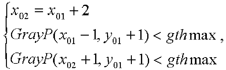 (1) updating, for the crack in the line, the starting point to PS = P(x 01 - 1, y 01 + 1), the end point to PE = P(x 01 +1, y 01 +1), the crack edge length to CL=Cl+2, the crack depth to CH=Ch+1, and the crack width to Cw = 1, in a case that
 (2) updating, for the crack in the line, the starting point to PS = P(x 01 +1, y 01 +1), the end point to PE = P(x 02 + 1, y 01 +1), the crack edge length to CL=Cl+2, the crack depth to CH=Ch+1, and the crack width to Cw = 1, in a case that
 (3) updating, for the crack in the line, the starting point to PS = P(x 01 -1, y 01 + 1), the end point to PE = P(x 02 , y 01 +1), the crack edge length to CL=Cl+2, the crack depth to CH=Ch+1, and the crack width to Cw = 2, in a case that
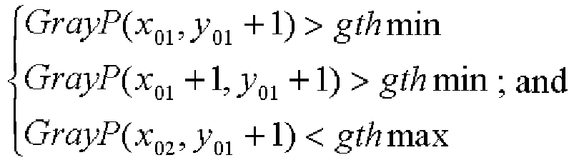 (4) updating, for the crack in the line, the starting point to PS = P(x 01, y 01 +1), the end point to PE = P(x 02 +1, y 01 +1), the crack edge length to CL=Cl+2, the crack depth to CH=Ch+1, and the crack width to Cw = 2, in a case that
 step 54, determining that
 (1) updating, for the crack in the line, the starting point to PS = P(x 01 - 1, y 01 + 1), the end point to PE = P(x 01 + 1, y 01 + 1), the crack edge length to CL=Cl+2, the crack depth to CH=Ch+1, and the crack width to Cw = 1, in a case that
 (2) updating, for the crack in the line, the starting point to PS = P(x 01, y 01 + 1), the end point to PE = P(x 01 + 2, y 01 +1), the crack edge length to CL=Cl+2, the crack depth to CH=Ch+1, and the crack width to Cw = 1, in a case that
 (3) updating, for the crack in the line, the starting point to PS = P(x 01 + 1, y 01 + 1), the end point to PE = P(x01 + 3, y 01 + 1), the crack edge length to CL=Cl+2, the crack depth to CH=Ch+1, and the crack width to Cw = 1, in a case that
 (4) updating, for the crack in the line, the starting point to PS = P(x 01 + 2, y01 + 1), the end point to PE = P(x 02 + 1, y 01 + 1), the crack edge length to CL-Cl+2, the crack depth to CH=Ch+1, and the crack width to Cw = 1, in a case that
 (5) updating, for the crack in the line, the starting point to PS = P(x 01 - 1, y 01 + 1), the end point to PE = P(x 01 + 2, y01 + 1), the crack edge length to CL=Cl+2, the crack depth to CH=Ch+1, and the crack width to Cw = 2, in a case that
 (6) updating, for the crack in the line, the starting point to PS = P(x 01, y 01 + 1), the end point to PE = P(x 01 + 3, y 01 + 1), the crack edge length to CL=Cl+2, the crack depth to CH=Ch+1, and the crack width to Cw = 2, in a case that
 (7) updating, for the crack in the line, the starting point to PS = P(x 01 + 1, y 01 + 1), the end point to PE = P(x 02 + 1, y 01 + 1), the crack edge length to CL=Cl+2, the crack depth to CH=Ch+1, and the crack width to Cw = 2, in a case that
 step 55, performing an iterative computation, repeatedly performing step 53 in a case that Cw = 1, and repeatedly performing step 54 in a case that Cw = 2 until a complete detection for a crack is finished.
Applications Claiming Priority (2)
| Application Number | Priority Date | Filing Date | Title |
|---|---|---|---|
| CN201510038608.8A CN104504727B (en) | 2015-01-26 | 2015-01-26 | banknote crack detection method and device |
| PCT/CN2015/083862 WO2016119410A1 (en) | 2015-01-26 | 2015-07-13 | Banknote crack detection method and apparatus |
Publications (3)
| Publication Number | Publication Date |
|---|---|
| EP3252710A1 true EP3252710A1 (en) | 2017-12-06 |
| EP3252710A4 EP3252710A4 (en) | 2018-01-17 |
| EP3252710B1 EP3252710B1 (en) | 2019-05-15 |
Family
ID=52946121
Family Applications (1)
| Application Number | Title | Priority Date | Filing Date |
|---|---|---|---|
| EP15879610.2A Not-in-force EP3252710B1 (en) | 2015-01-26 | 2015-07-13 | Banknote crack detection method and apparatus |
Country Status (8)
| Country | Link |
|---|---|
| US (1) | US10319172B2 (en) |
| EP (1) | EP3252710B1 (en) |
| CN (1) | CN104504727B (en) |
| HK (1) | HK1246476A1 (en) |
| RU (1) | RU2678493C1 (en) |
| TR (1) | TR201907436T4 (en) |
| WO (1) | WO2016119410A1 (en) |
| ZA (1) | ZA201705304B (en) |
Families Citing this family (11)
| Publication number | Priority date | Publication date | Assignee | Title |
|---|---|---|---|---|
| CN104504727B (en) * | 2015-01-26 | 2018-01-12 | 广州广电运通金融电子股份有限公司 | banknote crack detection method and device |
| CN104809800B (en) * | 2015-04-14 | 2017-09-29 | 深圳怡化电脑股份有限公司 | Extract preprocess method, splicing paper money recognition methods and the device of bank note splicing vestige |
| CN104851184B (en) * | 2015-05-27 | 2017-06-30 | 深圳怡化电脑股份有限公司 | A kind of recognition methods of horizontally-spliced bank note and device |
| CN108073927B (en) * | 2016-11-18 | 2020-05-15 | 深圳怡化电脑股份有限公司 | Character recognition method and device |
| CN107730706B (en) * | 2017-09-11 | 2019-08-27 | 深圳怡化电脑股份有限公司 | A kind of Paper Currency Identification, device, terminal device and readable storage medium storing program for executing |
| CN108109284B (en) * | 2017-12-05 | 2020-08-18 | 深圳怡化电脑股份有限公司 | Deposit transaction processing method, device and computer readable storage medium |
| CN108492446B (en) * | 2018-02-07 | 2020-09-15 | 深圳怡化电脑股份有限公司 | Paper money edge searching method and system |
| CN113139927B (en) * | 2020-01-02 | 2024-12-06 | 深圳怡化电脑股份有限公司 | Banknote crack detection method, device, equipment and readable medium |
| CN111260616A (en) * | 2020-01-13 | 2020-06-09 | 三峡大学 | An insulator crack detection method based on two-dimensional threshold segmentation optimization of Canny operator |
| CN118037734B (en) * | 2024-04-12 | 2024-06-18 | 济宁丰玺生物材料有限公司 | A quality detection method for fully degradable plastic products |
| CN120807490B (en) * | 2025-09-02 | 2025-11-18 | 安康市汉滨区周林生态农业开发有限公司 | A method, equipment and system for detecting the cell wall breakage rate of tea leaves |
Family Cites Families (17)
| Publication number | Priority date | Publication date | Assignee | Title |
|---|---|---|---|---|
| SU1575210A1 (en) * | 1988-04-19 | 1990-06-30 | Институт кибернетики им.В.М.Глушкова | Device for optical check of documents |
| DE19517194A1 (en) * | 1995-05-11 | 1996-11-14 | Giesecke & Devrient Gmbh | Device and method for checking sheet material, e.g. Banknotes or securities |
| JP4374143B2 (en) * | 2000-10-20 | 2009-12-02 | 日立オムロンターミナルソリューションズ株式会社 | Banknote discriminating apparatus and banknote automatic transaction apparatus provided with banknote discriminating apparatus |
| JP3846695B2 (en) * | 2001-07-30 | 2006-11-15 | 日立オムロンターミナルソリューションズ株式会社 | Banknote automatic transaction device |
| DE10242398B4 (en) * | 2002-09-12 | 2007-03-22 | Giesecke & Devrient Gmbh | Device for checking the condition of banknotes |
| US8041107B2 (en) * | 2004-09-07 | 2011-10-18 | National Printing Bureau, Incorporated Administrative Agency | OVD (optical variable device) inspection method and inspection apparatus |
| GB0427484D0 (en) | 2004-12-15 | 2005-01-19 | Money Controls Ltd | Acceptor device for sheet objects |
| WO2007044570A2 (en) * | 2005-10-05 | 2007-04-19 | Cummins-Allison Corp. | Currency processing system with fitness detection |
| JP5213649B2 (en) * | 2008-11-12 | 2013-06-19 | 日立オムロンターミナルソリューションズ株式会社 | Paper sheet processing apparatus and paper sheet processing program |
| CN101833815A (en) * | 2010-01-20 | 2010-09-15 | 上海古鳌电子机械有限公司 | Image identification system of paper money sorter and control method thereof |
| CN102236897A (en) * | 2011-05-09 | 2011-11-09 | 哈尔滨工业大学 | Method for detecting old and new as well as deformity of paper currency by sorting machine based on paper currency degeneration energy function |
| JP5635968B2 (en) * | 2011-12-26 | 2014-12-03 | 日立オムロンターミナルソリューションズ株式会社 | Banknote handling device and automatic cash transaction device |
| US8983168B2 (en) * | 2012-04-30 | 2015-03-17 | Ncr Corporation | System and method of categorising defects in a media item |
| DE102012223472A1 (en) * | 2012-12-17 | 2014-06-18 | Bundesdruckerei Gmbh | Method and device for producing a value and / or security document with an antenna structure |
| CN103324946B (en) | 2013-07-11 | 2016-08-17 | 广州广电运通金融电子股份有限公司 | A kind of method and system of paper money recognition classification |
| CN203950377U (en) * | 2014-07-08 | 2014-11-19 | 国家电网公司 | The built-in Paper currency identifier of a kind of electric power self-service payment terminal |
| CN104504727B (en) * | 2015-01-26 | 2018-01-12 | 广州广电运通金融电子股份有限公司 | banknote crack detection method and device |
-
2015
- 2015-01-26 CN CN201510038608.8A patent/CN104504727B/en active Active
- 2015-07-13 WO PCT/CN2015/083862 patent/WO2016119410A1/en not_active Ceased
- 2015-07-13 US US15/543,551 patent/US10319172B2/en active Active
- 2015-07-13 EP EP15879610.2A patent/EP3252710B1/en not_active Not-in-force
- 2015-07-13 RU RU2017129563A patent/RU2678493C1/en not_active IP Right Cessation
- 2015-07-13 HK HK18105762.5A patent/HK1246476A1/en unknown
- 2015-07-13 TR TR2019/07436T patent/TR201907436T4/en unknown
-
2017
- 2017-08-04 ZA ZA2017/05304A patent/ZA201705304B/en unknown
Also Published As
| Publication number | Publication date |
|---|---|
| EP3252710B1 (en) | 2019-05-15 |
| ZA201705304B (en) | 2019-07-31 |
| US20180025571A1 (en) | 2018-01-25 |
| HK1246476A1 (en) | 2018-09-07 |
| US10319172B2 (en) | 2019-06-11 |
| CN104504727B (en) | 2018-01-12 |
| WO2016119410A1 (en) | 2016-08-04 |
| RU2678493C1 (en) | 2019-01-29 |
| TR201907436T4 (en) | 2019-06-21 |
| EP3252710A4 (en) | 2018-01-17 |
| CN104504727A (en) | 2015-04-08 |
Similar Documents
| Publication | Publication Date | Title |
|---|---|---|
| EP3252710A1 (en) | Banknote crack detection method and apparatus | |
| EP2660787B1 (en) | Defect Categorisation in a digital image | |
| US7729536B2 (en) | Boundary extracting method, program, and device using the same | |
| EP3082112B1 (en) | Method and device for banknote identification based on thickness signal identification | |
| US20090252437A1 (en) | Image Skew Detection Apparatus And Methods | |
| EP3193313A1 (en) | Banknote recognition method based on sorter dust accumulation and sorter | |
| KR102123910B1 (en) | Serial number rcognition Apparatus and method for paper money using machine learning | |
| KR101595544B1 (en) | Apparatus and method for verifying of recognition accuracy of image device of intelligent transportation system | |
| RU2670049C1 (en) | Method and device for detecting overlapping banknotes | |
| CN101447023B (en) | Method and system for detecting human head | |
| EP3046083A1 (en) | Method and apparatus for detecting magnetic signal of paper money | |
| US9499006B2 (en) | Anti-counterfeiting feature generation method for valuable document and authentication method and device therefor | |
| EP2299388A2 (en) | Apparatus and method for detecting face | |
| CN109472279B (en) | Article identification method and device based on image processing | |
| CN107590902B (en) | A kind of recovery and identification method of banknote jamming when conveying | |
| US9047723B2 (en) | Defect categorization | |
| CN108492443B (en) | Method, device and equipment for detecting adhesive tape on paper money and storage medium | |
| CN111445433A (en) | Method and device for detecting blank page and fuzzy page of electronic file | |
| CN102592351B (en) | Authentication method of papery medium | |
| CN108010184B (en) | Method and device for detecting paper currency folding angle | |
| EP2821974A1 (en) | Paper medium identifying device and identifying method | |
| CN121095057B (en) | Elevator monitoring image stitching method for behavior monitoring | |
| KR20090062782A (en) | Media image detection device and method, and media handling system using same | |
| Rai et al. | Beyond ocrs for document blur estimation | |
| KR101958453B1 (en) | Financial device, apparatus and method for media recognition |
Legal Events
| Date | Code | Title | Description |
|---|---|---|---|
| STAA | Information on the status of an ep patent application or granted ep patent |
Free format text: STATUS: THE INTERNATIONAL PUBLICATION HAS BEEN MADE |
|
| PUAI | Public reference made under article 153(3) epc to a published international application that has entered the european phase |
Free format text: ORIGINAL CODE: 0009012 |
|
| STAA | Information on the status of an ep patent application or granted ep patent |
Free format text: STATUS: REQUEST FOR EXAMINATION WAS MADE |
|
| 17P | Request for examination filed |
Effective date: 20170721 |
|
| AK | Designated contracting states |
Kind code of ref document: A1 Designated state(s): AL AT BE BG CH CY CZ DE DK EE ES FI FR GB GR HR HU IE IS IT LI LT LU LV MC MK MT NL NO PL PT RO RS SE SI SK SM TR |
|
| AX | Request for extension of the european patent |
Extension state: BA ME |
|
| A4 | Supplementary search report drawn up and despatched |
Effective date: 20171219 |
|
| RIC1 | Information provided on ipc code assigned before grant |
Ipc: G06T 7/00 20170101AFI20171213BHEP |
|
| DAV | Request for validation of the european patent (deleted) | ||
| DAX | Request for extension of the european patent (deleted) | ||
| STAA | Information on the status of an ep patent application or granted ep patent |
Free format text: STATUS: EXAMINATION IS IN PROGRESS |
|
| REG | Reference to a national code |
Ref country code: HK Ref legal event code: DE Ref document number: 1246476 Country of ref document: HK |
|
| 17Q | First examination report despatched |
Effective date: 20180809 |
|
| RIC1 | Information provided on ipc code assigned before grant |
Ipc: G06T 7/187 20170101ALI20181010BHEP Ipc: G06T 7/00 20170101AFI20181010BHEP |
|
| GRAP | Despatch of communication of intention to grant a patent |
Free format text: ORIGINAL CODE: EPIDOSNIGR1 |
|
| STAA | Information on the status of an ep patent application or granted ep patent |
Free format text: STATUS: GRANT OF PATENT IS INTENDED |
|
| INTG | Intention to grant announced |
Effective date: 20181126 |
|
| GRAS | Grant fee paid |
Free format text: ORIGINAL CODE: EPIDOSNIGR3 |
|
| GRAA | (expected) grant |
Free format text: ORIGINAL CODE: 0009210 |
|
| STAA | Information on the status of an ep patent application or granted ep patent |
Free format text: STATUS: THE PATENT HAS BEEN GRANTED |
|
| AK | Designated contracting states |
Kind code of ref document: B1 Designated state(s): AL AT BE BG CH CY CZ DE DK EE ES FI FR GB GR HR HU IE IS IT LI LT LU LV MC MK MT NL NO PL PT RO RS SE SI SK SM TR |
|
| REG | Reference to a national code |
Ref country code: CH Ref legal event code: EP |
|
| REG | Reference to a national code |
Ref country code: DE Ref legal event code: R096 Ref document number: 602015030567 Country of ref document: DE |
|
| REG | Reference to a national code |
Ref country code: IE Ref legal event code: FG4D |
|
| REG | Reference to a national code |
Ref country code: NL Ref legal event code: MP Effective date: 20190515 |
|
| REG | Reference to a national code |
Ref country code: LT Ref legal event code: MG4D |
|
| PG25 | Lapsed in a contracting state [announced via postgrant information from national office to epo] |
Ref country code: SE Free format text: LAPSE BECAUSE OF FAILURE TO SUBMIT A TRANSLATION OF THE DESCRIPTION OR TO PAY THE FEE WITHIN THE PRESCRIBED TIME-LIMIT Effective date: 20190515 Ref country code: NL Free format text: LAPSE BECAUSE OF FAILURE TO SUBMIT A TRANSLATION OF THE DESCRIPTION OR TO PAY THE FEE WITHIN THE PRESCRIBED TIME-LIMIT Effective date: 20190515 Ref country code: ES Free format text: LAPSE BECAUSE OF FAILURE TO SUBMIT A TRANSLATION OF THE DESCRIPTION OR TO PAY THE FEE WITHIN THE PRESCRIBED TIME-LIMIT Effective date: 20190515 Ref country code: LT Free format text: LAPSE BECAUSE OF FAILURE TO SUBMIT A TRANSLATION OF THE DESCRIPTION OR TO PAY THE FEE WITHIN THE PRESCRIBED TIME-LIMIT Effective date: 20190515 Ref country code: FI Free format text: LAPSE BECAUSE OF FAILURE TO SUBMIT A TRANSLATION OF THE DESCRIPTION OR TO PAY THE FEE WITHIN THE PRESCRIBED TIME-LIMIT Effective date: 20190515 Ref country code: AL Free format text: LAPSE BECAUSE OF FAILURE TO SUBMIT A TRANSLATION OF THE DESCRIPTION OR TO PAY THE FEE WITHIN THE PRESCRIBED TIME-LIMIT Effective date: 20190515 Ref country code: HR Free format text: LAPSE BECAUSE OF FAILURE TO SUBMIT A TRANSLATION OF THE DESCRIPTION OR TO PAY THE FEE WITHIN THE PRESCRIBED TIME-LIMIT Effective date: 20190515 Ref country code: PT Free format text: LAPSE BECAUSE OF FAILURE TO SUBMIT A TRANSLATION OF THE DESCRIPTION OR TO PAY THE FEE WITHIN THE PRESCRIBED TIME-LIMIT Effective date: 20190915 Ref country code: NO Free format text: LAPSE BECAUSE OF FAILURE TO SUBMIT A TRANSLATION OF THE DESCRIPTION OR TO PAY THE FEE WITHIN THE PRESCRIBED TIME-LIMIT Effective date: 20190815 |
|
| PGFP | Annual fee paid to national office [announced via postgrant information from national office to epo] |
Ref country code: TR Payment date: 20190712 Year of fee payment: 5 Ref country code: DE Payment date: 20190730 Year of fee payment: 5 Ref country code: IT Payment date: 20190719 Year of fee payment: 5 Ref country code: FR Payment date: 20190724 Year of fee payment: 5 |
|
| PG25 | Lapsed in a contracting state [announced via postgrant information from national office to epo] |
Ref country code: GR Free format text: LAPSE BECAUSE OF FAILURE TO SUBMIT A TRANSLATION OF THE DESCRIPTION OR TO PAY THE FEE WITHIN THE PRESCRIBED TIME-LIMIT Effective date: 20190816 Ref country code: LV Free format text: LAPSE BECAUSE OF FAILURE TO SUBMIT A TRANSLATION OF THE DESCRIPTION OR TO PAY THE FEE WITHIN THE PRESCRIBED TIME-LIMIT Effective date: 20190515 Ref country code: RS Free format text: LAPSE BECAUSE OF FAILURE TO SUBMIT A TRANSLATION OF THE DESCRIPTION OR TO PAY THE FEE WITHIN THE PRESCRIBED TIME-LIMIT Effective date: 20190515 Ref country code: BG Free format text: LAPSE BECAUSE OF FAILURE TO SUBMIT A TRANSLATION OF THE DESCRIPTION OR TO PAY THE FEE WITHIN THE PRESCRIBED TIME-LIMIT Effective date: 20190815 |
|
| PGFP | Annual fee paid to national office [announced via postgrant information from national office to epo] |
Ref country code: GB Payment date: 20190725 Year of fee payment: 5 |
|
| PG25 | Lapsed in a contracting state [announced via postgrant information from national office to epo] |
Ref country code: DK Free format text: LAPSE BECAUSE OF FAILURE TO SUBMIT A TRANSLATION OF THE DESCRIPTION OR TO PAY THE FEE WITHIN THE PRESCRIBED TIME-LIMIT Effective date: 20190515 Ref country code: EE Free format text: LAPSE BECAUSE OF FAILURE TO SUBMIT A TRANSLATION OF THE DESCRIPTION OR TO PAY THE FEE WITHIN THE PRESCRIBED TIME-LIMIT Effective date: 20190515 Ref country code: CZ Free format text: LAPSE BECAUSE OF FAILURE TO SUBMIT A TRANSLATION OF THE DESCRIPTION OR TO PAY THE FEE WITHIN THE PRESCRIBED TIME-LIMIT Effective date: 20190515 Ref country code: SK Free format text: LAPSE BECAUSE OF FAILURE TO SUBMIT A TRANSLATION OF THE DESCRIPTION OR TO PAY THE FEE WITHIN THE PRESCRIBED TIME-LIMIT Effective date: 20190515 |
|
| REG | Reference to a national code |
Ref country code: DE Ref legal event code: R097 Ref document number: 602015030567 Country of ref document: DE |
|
| PG25 | Lapsed in a contracting state [announced via postgrant information from national office to epo] |
Ref country code: SM Free format text: LAPSE BECAUSE OF FAILURE TO SUBMIT A TRANSLATION OF THE DESCRIPTION OR TO PAY THE FEE WITHIN THE PRESCRIBED TIME-LIMIT Effective date: 20190515 Ref country code: MC Free format text: LAPSE BECAUSE OF FAILURE TO SUBMIT A TRANSLATION OF THE DESCRIPTION OR TO PAY THE FEE WITHIN THE PRESCRIBED TIME-LIMIT Effective date: 20190515 |
|
| REG | Reference to a national code |
Ref country code: CH Ref legal event code: PL |
|
| PLBE | No opposition filed within time limit |
Free format text: ORIGINAL CODE: 0009261 |
|
| STAA | Information on the status of an ep patent application or granted ep patent |
Free format text: STATUS: NO OPPOSITION FILED WITHIN TIME LIMIT |
|
| REG | Reference to a national code |
Ref country code: BE Ref legal event code: MM Effective date: 20190731 |
|
| 26N | No opposition filed |
Effective date: 20200218 |
|
| PG25 | Lapsed in a contracting state [announced via postgrant information from national office to epo] |
Ref country code: PL Free format text: LAPSE BECAUSE OF FAILURE TO SUBMIT A TRANSLATION OF THE DESCRIPTION OR TO PAY THE FEE WITHIN THE PRESCRIBED TIME-LIMIT Effective date: 20190515 |
|
| PG25 | Lapsed in a contracting state [announced via postgrant information from national office to epo] |
Ref country code: BE Free format text: LAPSE BECAUSE OF NON-PAYMENT OF DUE FEES Effective date: 20190731 Ref country code: SI Free format text: LAPSE BECAUSE OF FAILURE TO SUBMIT A TRANSLATION OF THE DESCRIPTION OR TO PAY THE FEE WITHIN THE PRESCRIBED TIME-LIMIT Effective date: 20190515 Ref country code: LU Free format text: LAPSE BECAUSE OF NON-PAYMENT OF DUE FEES Effective date: 20190713 Ref country code: LI Free format text: LAPSE BECAUSE OF NON-PAYMENT OF DUE FEES Effective date: 20190731 Ref country code: CH Free format text: LAPSE BECAUSE OF NON-PAYMENT OF DUE FEES Effective date: 20190731 |
|
| PG25 | Lapsed in a contracting state [announced via postgrant information from national office to epo] |
Ref country code: IE Free format text: LAPSE BECAUSE OF NON-PAYMENT OF DUE FEES Effective date: 20190713 |
|
| REG | Reference to a national code |
Ref country code: DE Ref legal event code: R119 Ref document number: 602015030567 Country of ref document: DE |
|
| REG | Reference to a national code |
Ref country code: AT Ref legal event code: UEP Ref document number: 1134321 Country of ref document: AT Kind code of ref document: T Effective date: 20190515 |
|
| GBPC | Gb: european patent ceased through non-payment of renewal fee |
Effective date: 20200713 |
|
| PG25 | Lapsed in a contracting state [announced via postgrant information from national office to epo] |
Ref country code: GB Free format text: LAPSE BECAUSE OF NON-PAYMENT OF DUE FEES Effective date: 20200713 Ref country code: FR Free format text: LAPSE BECAUSE OF NON-PAYMENT OF DUE FEES Effective date: 20200731 Ref country code: RO Free format text: LAPSE BECAUSE OF FAILURE TO SUBMIT A TRANSLATION OF THE DESCRIPTION OR TO PAY THE FEE WITHIN THE PRESCRIBED TIME-LIMIT Effective date: 20190515 |
|
| PG25 | Lapsed in a contracting state [announced via postgrant information from national office to epo] |
Ref country code: CY Free format text: LAPSE BECAUSE OF FAILURE TO SUBMIT A TRANSLATION OF THE DESCRIPTION OR TO PAY THE FEE WITHIN THE PRESCRIBED TIME-LIMIT Effective date: 20190515 Ref country code: DE Free format text: LAPSE BECAUSE OF NON-PAYMENT OF DUE FEES Effective date: 20210202 |
|
| PG25 | Lapsed in a contracting state [announced via postgrant information from national office to epo] |
Ref country code: IS Free format text: LAPSE BECAUSE OF FAILURE TO SUBMIT A TRANSLATION OF THE DESCRIPTION OR TO PAY THE FEE WITHIN THE PRESCRIBED TIME-LIMIT Effective date: 20190915 |
|
| PG25 | Lapsed in a contracting state [announced via postgrant information from national office to epo] |
Ref country code: HU Free format text: LAPSE BECAUSE OF FAILURE TO SUBMIT A TRANSLATION OF THE DESCRIPTION OR TO PAY THE FEE WITHIN THE PRESCRIBED TIME-LIMIT; INVALID AB INITIO Effective date: 20150713 Ref country code: MT Free format text: LAPSE BECAUSE OF FAILURE TO SUBMIT A TRANSLATION OF THE DESCRIPTION OR TO PAY THE FEE WITHIN THE PRESCRIBED TIME-LIMIT Effective date: 20190515 |
|
| REG | Reference to a national code |
Ref country code: AT Ref legal event code: MM01 Ref document number: 1134321 Country of ref document: AT Kind code of ref document: T Effective date: 20200713 |
|
| PG25 | Lapsed in a contracting state [announced via postgrant information from national office to epo] |
Ref country code: AT Free format text: LAPSE BECAUSE OF NON-PAYMENT OF DUE FEES Effective date: 20200713 Ref country code: IT Free format text: LAPSE BECAUSE OF NON-PAYMENT OF DUE FEES Effective date: 20200713 |
|
| PG25 | Lapsed in a contracting state [announced via postgrant information from national office to epo] |
Ref country code: TR Free format text: LAPSE BECAUSE OF NON-PAYMENT OF DUE FEES Effective date: 20200713 Ref country code: MK Free format text: LAPSE BECAUSE OF FAILURE TO SUBMIT A TRANSLATION OF THE DESCRIPTION OR TO PAY THE FEE WITHIN THE PRESCRIBED TIME-LIMIT Effective date: 20190515 |
|
| REG | Reference to a national code |
Ref country code: HK Ref legal event code: WD Ref document number: 1246476 Country of ref document: HK |