EP3252413A1 - Method and device for cooling a bulk good layer on a supply grid - Google Patents
Method and device for cooling a bulk good layer on a supply grid Download PDFInfo
- Publication number
- EP3252413A1 EP3252413A1 EP17178000.0A EP17178000A EP3252413A1 EP 3252413 A1 EP3252413 A1 EP 3252413A1 EP 17178000 A EP17178000 A EP 17178000A EP 3252413 A1 EP3252413 A1 EP 3252413A1
- Authority
- EP
- European Patent Office
- Prior art keywords
- grate
- planks
- movement
- cooling air
- conveying
- Prior art date
- Legal status (The legal status is an assumption and is not a legal conclusion. Google has not performed a legal analysis and makes no representation as to the accuracy of the status listed.)
- Granted
Links
- 238000001816 cooling Methods 0.000 title claims abstract description 58
- 238000000034 method Methods 0.000 title claims abstract description 15
- 239000013590 bulk material Substances 0.000 claims abstract description 54
- 230000000295 complement effect Effects 0.000 claims abstract description 5
- 230000001154 acute effect Effects 0.000 claims description 5
- 230000000694 effects Effects 0.000 claims description 3
- 239000004568 cement Substances 0.000 abstract description 3
- JEIPFZHSYJVQDO-UHFFFAOYSA-N iron(III) oxide Inorganic materials O=[Fe]O[Fe]=O JEIPFZHSYJVQDO-UHFFFAOYSA-N 0.000 description 11
- 238000009423 ventilation Methods 0.000 description 9
- 210000003027 ear inner Anatomy 0.000 description 7
- 238000005516 engineering process Methods 0.000 description 5
- 210000001503 joint Anatomy 0.000 description 5
- 206010012735 Diarrhoea Diseases 0.000 description 4
- 238000007664 blowing Methods 0.000 description 4
- 238000010276 construction Methods 0.000 description 3
- 239000000428 dust Substances 0.000 description 3
- 230000001737 promoting effect Effects 0.000 description 3
- 230000008901 benefit Effects 0.000 description 2
- 230000008859 change Effects 0.000 description 2
- 230000008569 process Effects 0.000 description 2
- 230000008439 repair process Effects 0.000 description 2
- 239000007787 solid Substances 0.000 description 2
- 241001136792 Alle Species 0.000 description 1
- 235000008733 Citrus aurantifolia Nutrition 0.000 description 1
- 206010010219 Compulsions Diseases 0.000 description 1
- 235000011941 Tilia x europaea Nutrition 0.000 description 1
- 238000005273 aeration Methods 0.000 description 1
- 230000004888 barrier function Effects 0.000 description 1
- 238000005266 casting Methods 0.000 description 1
- 230000000741 diarrhetic effect Effects 0.000 description 1
- 238000007599 discharging Methods 0.000 description 1
- 238000009826 distribution Methods 0.000 description 1
- 238000002474 experimental method Methods 0.000 description 1
- 230000002349 favourable effect Effects 0.000 description 1
- 229910052602 gypsum Inorganic materials 0.000 description 1
- 239000010440 gypsum Substances 0.000 description 1
- 238000010438 heat treatment Methods 0.000 description 1
- 238000007689 inspection Methods 0.000 description 1
- 238000009434 installation Methods 0.000 description 1
- 239000004571 lime Substances 0.000 description 1
- 238000012423 maintenance Methods 0.000 description 1
- 238000004519 manufacturing process Methods 0.000 description 1
- 239000000463 material Substances 0.000 description 1
- 239000002245 particle Substances 0.000 description 1
- 230000000149 penetrating effect Effects 0.000 description 1
- 108090000623 proteins and genes Proteins 0.000 description 1
- 230000000284 resting effect Effects 0.000 description 1
- 238000007789 sealing Methods 0.000 description 1
- 238000007493 shaping process Methods 0.000 description 1
- 241000894007 species Species 0.000 description 1
- 238000003860 storage Methods 0.000 description 1
- 239000002023 wood Substances 0.000 description 1
Images


Classifications
-
- F—MECHANICAL ENGINEERING; LIGHTING; HEATING; WEAPONS; BLASTING
- F27—FURNACES; KILNS; OVENS; RETORTS
- F27D—DETAILS OR ACCESSORIES OF FURNACES, KILNS, OVENS, OR RETORTS, IN SO FAR AS THEY ARE OF KINDS OCCURRING IN MORE THAN ONE KIND OF FURNACE
- F27D15/00—Handling or treating discharged material; Supports or receiving chambers therefor
- F27D15/02—Cooling
- F27D15/0206—Cooling with means to convey the charge
- F27D15/0213—Cooling with means to convey the charge comprising a cooling grate
-
- B—PERFORMING OPERATIONS; TRANSPORTING
- B65—CONVEYING; PACKING; STORING; HANDLING THIN OR FILAMENTARY MATERIAL
- B65G—TRANSPORT OR STORAGE DEVICES, e.g. CONVEYORS FOR LOADING OR TIPPING, SHOP CONVEYOR SYSTEMS OR PNEUMATIC TUBE CONVEYORS
- B65G25/00—Conveyors comprising a cyclically-moving, e.g. reciprocating, carrier or impeller which is disengaged from the load during the return part of its movement
- B65G25/04—Conveyors comprising a cyclically-moving, e.g. reciprocating, carrier or impeller which is disengaged from the load during the return part of its movement the carrier or impeller having identical forward and return paths of movement, e.g. reciprocating conveyors
- B65G25/06—Conveyors comprising a cyclically-moving, e.g. reciprocating, carrier or impeller which is disengaged from the load during the return part of its movement the carrier or impeller having identical forward and return paths of movement, e.g. reciprocating conveyors having carriers, e.g. belts
- B65G25/065—Reciprocating floor conveyors
-
- F—MECHANICAL ENGINEERING; LIGHTING; HEATING; WEAPONS; BLASTING
- F26—DRYING
- F26B—DRYING SOLID MATERIALS OR OBJECTS BY REMOVING LIQUID THEREFROM
- F26B17/00—Machines or apparatus for drying materials in loose, plastic, or fluidised form, e.g. granules, staple fibres, with progressive movement
- F26B17/26—Machines or apparatus for drying materials in loose, plastic, or fluidised form, e.g. granules, staple fibres, with progressive movement with movement performed by reciprocating or oscillating conveyors propelling materials over stationary surfaces; with movement performed by reciprocating or oscillating shelves, sieves, or trays
Definitions
- the invention relates to a method and a device for cooling a bulk material layer lying on a conveyor grate by means of cooling air blown out through the grate bottom, wherein the grate bottom is formed of a plurality of planks arranged transversely to the conveying direction and relatively longitudinally moving planks with movement gaps therebetween permitting a cooling air passage.
- planks with the bulk material stored thereon are moved back and forth individually or in groups according to a specific movement pattern such that a net forward movement of the bulk material in the conveying direction is established.
- the cooling of the bulk material is generally carried out in the planks formed blow-out, is blown over the arranged in below the grate floor cooling air ducts or open chambers cooling air into the bulk material located above.
- a particular constructive problem is the movement gaps between the mutually moved planks, which must be designed so that rust rust through them is avoided.
- a disadvantage of the known design is that the movement gaps are relatively wide because of the labyrinth structures formed therein, so that form over this non-aerated and not participating in the conveying process bulk material, whereby the delivery efficiency of the conveyor grate is deteriorated.
- the planks In order to achieve an acceptable ratio of promotional to non-promotional grate floor surfaces, the planks must also be made relatively wide. After stopping the conveying movements, bulk material remains approximately roof-shaped on the planks. The amount of bulk material depends on the roof height, and this is based on the width of the planks, taking into account the predetermined slope angle of the bulk material. That The wider the planks are, the greater the amount of bulk remaining on them.
- the Danish patent DK 1 999 014 03 shows a conveyor grate the beginning mentioned type, in which also allow the movement column a cooling air passage.
- labyrinth structures are provided in the wide movement gaps, which should prevent diarrhea of bulk material in the arranged under the grate chamber.
- These labyrinth structures are formed by two interlocking angle profiles such that the course of the movement gap in a cross section is approximately meandering.
- at least the coarse-grained portion of the bulk material will fall into the movement gap up to the channel formed by the lower angle profile and only through the subsequent vertically upwardly leading portion of the labyrinth course at one Failed to fall into the chamber located under the rust floor.
- the invention has for its object to provide a constructive, manufacturing technology and assembly technology simple conveyor grate referred to in the preamble of claim 1 species, which makes it possible to narrow the movement column narrow and thus the planks against the known solutions according to the prior art, so the amount of not at the Promoting participating as well as lying after emptying the conveyor grate remaining bulk material is as low as possible and thus the degree of emptying is improved.
- Another object of the invention is to further improve a method referred to in the preamble of claim 12 such that friction losses in the movement gap are avoided and thus the drive efficiency is improved.
- the invention is based on the finding that the example of EP-A-0 167 658 and EP 0 549 816 B2 known design of formed between profiled slats, fail-safe blow-out slots can also be used with advantage for the design of movement gaps between each other moved planks.
- the invention is based, on the one hand, on a conveyor grate for conveying and cooling bulk material comprising a grate floor with a plurality of planks arranged transversely to the conveying direction next to one another on associated support structures, relative to each other individually or in groups operatively longitudinally moved planks with intermediate movement gaps allowing a cooling air passage. It is provided according to the invention that the mutually facing side edges or side edge regions of two mutually longitudinally moving planks form two mutually complementary profiles, between which a narrow movement gap is formed.
- planks are made, for example, by precise casting or drawing process.
- the movement gaps are formed in a simple manner at the same time and without additional installation effort, which can be more or less arbitrarily narrow, so that coarser grain already is mechanically kept away.
- the movement gaps are each siphon-like curved with at least one upwardly directed inlet portion, an adjoining downwardly directed intermediate portion and an adjoining, upwardly directed outlet portion are formed.
- the downwardly directed for the cooling air intermediate portion forms for any possibly in the movement gap penetrating bulk grains an upwardly directed portion which forms an effective barrier against Rost trimfall.
- the movement gaps emerge at an acute angle obliquely to the bottom surface of the grate.
- the air outlet from an obliquely upward gap at the same outflow velocity is a more effective obstacle against ingress of bulk material as a vertical gap, which is protected only by blown cooling air against ingress of bulk material.
- the exit angle of the movement gaps is selected so that the exiting cooling air due to the Coanda effect to the grid bottom surface applies.
- the cooling air applied horizontally to the surface of the grate floor effectively keeps away fine grain from the movement gap, in particular in the interstices of the bed due to the flow of air.
- the discharge direction of the movement gaps extends in each case from the bottom of the grate to the bottom of the grate.
- the width of the movement gaps is preferably chosen and the width matched the planks that they do not close at a thermal expansion of the planks in the transverse direction in any case and that the possible constriction is compensated by a corresponding, preferably automatic power increase of the cooling air fans.
- the performance of the cooling air fans is thus set in each phase of operation so that adjusts the desired cooling air for the cooling air through the movement gaps cooling air.
- planks are each secured to this along its entire length supporting longitudinal beams, which form the second level below the planks.
- planks are connected via heat insulating insulating elements to the support structures supporting them.
- planks are mounted on a plurality of longitudinally successively arranged cross members, which form the second level.
- Such a construction makes it possible to keep the number of supports in the second plane smaller than the number of planks. It also allows better access to the bottom of the grate, for example for maintenance or repair purposes.
- planks themselves may be integrally formed and extend over the entire length of the grate floor.
- the planks are composed of a plurality of longitudinally successively arranged and interconnected plank sections. This embodiment allows the grate floor length according to the pitch of the plank sections to design arbitrarily.
- the plank sections should preferably abut each other via butt joints oriented obliquely forwardly from bottom to top. Upon elongation of the plank sections due to thermal expansion, the respective rear plank section shifts towards the front plank section forward and upward and forms a small step that supports the entrainment of the conveyed material through the plank.
- the dimensions of the movement gaps are exactly matched to the sealing function on the one hand and the cooling function on the other hand and remain largely unchanged even during a longer period of operation of the conveyor grate.
- the support structures supporting the planks by means of wear-free linear guides according to the known principle of the pendulum spring rods are stored.
- the invention is based on a method for cooling a bulk material layer lying on a conveyor grate by means of cooling air blown out through the grate bottom, wherein the grate bottom is formed by a plurality of planks arranged transversely to the conveying direction and relatively longitudinally moving planks with movement gaps therebetween, and wherein cooling air passes through the movement column can escape.
- the invention provides that a defined, free from the bulk material free gap and the pressure difference across the gap exactly determinable amount of cooling air is blown out, which is at least sufficient to blow the movement gaps completely free.
- the movement gaps can be made narrow, they form for coarse bulk, ie for bulk material with a grain size that is above the gap width, per se an absolute diarrheal obstacle. Finer bulk material that can get into the movement gaps, can be completely blown out completely by means of a suitably sized, guided by the movement gaps amount of cooling air, so that a perfect seal against rust diarrhea is reached. Since there is no friction preventing the plank movement in a movement gap free from bulk material, the drive power compared to the known solutions can also be reduced. Since all ventilation gaps are at the same time movement gaps, they are constantly kept clean.
- At least a majority of the total cooling air is blown through the movement gaps.
- a method with cooling air outlet through the movement gaps is in the above-mentioned Danish patent specification DK 1999 014 03 been described. In this known method, however, it is assumed that at least coarser bulk material enters the movement gaps, so that only a not exactly defined amount of cooling air sufficient to blow a dust content of the bulk material freely, can pass through the filled with coarse bulk material movement gap. The larger proportion of the cooling air is blown out through openings formed in the planks.
- the cooling air is blown out through the movement gaps such that they are completely blown free.
- the possibly remaining proportion of the cooling air can be formed, for example, by blow slots formed in the planks and extending transversely to the conveying direction, approximately in accordance with the above EP-A-0 176 658 or EP 0 549 816 B2 or other suitable fissile openings.
- the majority of the cooling air can be up to the entire share in the limit case, in which case account additional blast openings in the planks.
- a particular advantage of the cooling air blown off obstacle-free over the movement gaps is seen in the fact that while the rust resistance for the cooling air always remains the same and the air flow remains defined. Rost trimfall is safer prevented than by bulk filled mazes.
- the guided through the movement gaps cooling air is preferably blown at an acute angle obliquely to the grate floor surface, and preferably in each case from the edge of the grate floor to the bottom of the grate, as already stated
- Fig. 1 schematically shows three juxtaposed planks 2, 4, 6 of a conventional conveyor grate with movement gaps 8, 10 arranged therebetween.
- the movement gaps 8, 10 are made relatively wide to accommodate in them the labyrinth structures, not shown in the figure for reasons of clarity, the to prevent diarrhea of bulk material in a below the planks 2, 4, 6 located chamber.
- the movement gaps 8, 10 are filled with bulk material.
- the area above the movement gaps 8, 10 does not participate in the ventilation.
- the planks 2, 4, 6 have to be made relatively wide.
- an open grate area of, for example, 2.5% of the total grate area is aimed at, wherein the in Fig. 1 shown conventional rust must distribute the exhaust holes on the plank surface, since the movement gaps are not available as exhaust openings.
- the Fig. 1 can recognize, remain after stopping the conveyor grate on the planks 2, 4, 6 bulk material cone whose height depends on the one hand on the respective cone foot width and on the other hand on the natural slope angle of the bulk material. This means that the wider the planks, the higher the bulk material cone and the larger the quantity of bulk material remaining after the conveyor grate has been shut down, which then occasionally has to be removed by hand or by means of separate equipment.
- Fig. 2 shows schematically a partial cross-section through a grate floor according to the present invention, in which the mutually facing side edges or side edge regions of two juxtaposed planks 12 each form two mutually complementary, interlocking profiles, between which a movement gap 14 is formed.
- Fig. 3 can recognize the movement column 14 are each siphon-like curved and have, from bottom to top, an upwardly directed inlet portion 16, an adjoining downwardly directed intermediate portion 18 and an adjoining upwardly directed outlet portion 20.
- the movement gaps 14 occur at an acute angle ⁇ obliquely to rust base surface 22 from.
- the exit angle ⁇ of the movement gaps 14 is selected so that the exiting cooling air due to the Coanda effect to the grid bottom surface 22 applies.
- the width of the movement gaps 14 is designed and matched with the width of the planks 12 that the movement gaps in a thermal expansion of the planks in the transverse direction do not close in any case and beyond remain within a compensated by controlling the cooling air fans area.
- these relationships exemplified herein change as an increasing proportion of the cooling air is blown out through blow holes formed in the planks, that is, from a ventilation viewpoint, the planks become wider. From conveyor technology point of view, this is disadvantageous because the bulk material cones are higher.
- a movement gap with a gap width of 3 mm in the cold state of the grate is narrowed at an exit angle ⁇ of 35 ° when heated by 500 ° C. to 2.4 mm.
- the required pressure increase at the Entrance of the column is of an order of magnitude, which lies within the usual control range of the cooling air fans.
- the effective width B of the planks 12 can be kept much narrower than in the example of Fig. 1 , so that the height H of the bulk material cone and thus the amount of bulk material remaining after stopping the conveyor grate is considerably smaller; In addition, bulk material cones continue to fall over the movement gaps, as they are constantly blown out completely.
- Fig. 1 and 2 shows, at a triple effective width 3B of the conventional planks 2, 4, 6 compared to the planks 12, the theoretically this amount of bulk material nine times.
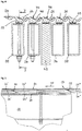
- Fig. 4 shows a partial cross-section through a conveyor grate, in which each moving plank 24, 26, 28, 30 is mounted on a support this along its entire length longitudinal beams 32, 34, 36 and 38, respectively.
- the longitudinal members are connected in a manner not shown here with a drive device for the longitudinal movement of the planks.
- middle plank 40 represents a fixed plank which is fixedly connected to the grate floor structure 42.
- a respective movement gap 44 and 46 are formed between the fixed plank 40 and arranged next to this moving planks 26 and 28, respectively.
- Fig. 5 shows a longitudinal section along the section line VV in Fig. 4 , It can be seen that the planks 24 and 26 respectively of plank sections 24 ', 24 ", 24'” and 26 ', 26 “, 26'” are composed.
- the plank sections are connected to each other in a manner not shown and over in Fig. 4 33 denotes heat-insulating elements connected to these supporting support structures.
- the plank sections abut obliquely from the bottom to the top, ie in the conveying direction 48 aligned butt joints 50 and 52 to each other.
- the connection of the plank sections is structurally designed so that they can move against each other at the butt joints 50, 52.
- each of the rear plank portion, for example 24 "', opposite the previous plank portion 24" forms a step 54 which is not harmful, but rather causes entrainment of the bulk material during the advancing movement and exposes at least the lower layer of the bulk material to a small falling movement during the return stroke , which propagates in the bulk bed, thereby assisting grain sorting by discharging the fine grain which can be moved by aeration.
- At least one amount of cooling air is blown out via the movement gaps 14, which is sufficient to blow them completely free.
- the predominant to entire proportion of the intended cooling air quantity is passed through the movement gaps.
- Fig. 6 shows a schematic cross section through an arranged between two solid side walls 60, 62 grate floor 64.
- Each of the side walls 60 and 62 is associated with a fixed, sealed against this edge plank 66 and 68 respectively, which adjoin the respective bottom of the grate center Plank 70 and 72 forms a movement gap.
- These planks 70 and 72 are, for example longitudinally movable planks, to which, for example, movable planks B and solid planks F connect to the bottom of the grate, which also form movement gaps with one another, as has already been described.
- a solid center plank 74 is arranged, which likewise forms a movement gap with the respective adjacent inner movable plank 76 or 78.
- Fig. 6 can recognize, are the movement column in the Fig. 6 on the right side of the grate on the one hand and the left side of the grate on the other hand, in each case directed towards the center plane 80, as already described.
- the Fig. 6 shows an example of a conveyor grate, in which the entire cooling air is blown through the associated with the air box 82 located under the grate floor moving gaps, the open grate surface is determined by the ratio of the gap surface to the total area of the grate floor, as also already described ,
- Fig. 7 shows an example of a grate floor 90, in which the relatively movable planks 92, 94, 96 are each formed as elongated boxes, which provided in the bottom openings 98, 100, 102 with a located below the grate floor air box or an air chamber 103rd keep in touch.
- mutually complementary, interlocking profiles 104, 106 are arranged, between which a movement gap 108 is formed.
- a predetermined, defined proportion of the cooling air is blown out.
- blowing slots 112 extending approximately at the top of the boxes, in each case transversely to the conveying direction represented by the arrow 110, are approximately in accordance with the above EP 0 549 816 B2 provided over which the remaining portion of the cooling air is blown out.
- Fig. 7 also shows an example in which the planks formed in this case as rigid boxes 92-96 are mounted on cross beams, of which a cross member 114 is shown.
Abstract
Die vorliegende Erfindung betrifft einen Förderrost zum Fördern und Kühlen von Schüttgut, beispielsweise Zementklinker, umfassend einen Rostboden mit mehreren quer zur Förderrichtung nebeneinander auf zugeordneten Tragstrukturen angeordneten, relativ zueinander einzeln oder in Gruppen betriebsmäßig längs bewegten Planken 12 mit dazwischen liegenden, als Ausblasöffnungen ausgebildeten Bewegungsspalten 14, sowie ein Verfahren zum Betreiben eines derartigen Förderrostes. Dabei ist vorgesehen, dass die einander zugewandten Seitenkanten bzw. Seitenkantenbereiche zweier nebeneinander angeordneter Planken 12 zwei zueinander komplementäre, ineinander greifende Profile bilden, zwischen denen der Bewegungsspalt 14 gebildet ist. Gemäß dem erfindungsgemäßen Verfahren wird durch die Bewegungsspalte 14 zumindest eine Kühlluftmenge ausgeblasen, die ausreicht, die Bewegungsspalte 14 vollständig frei zu blasen.The present invention relates to a conveyor grate for conveying and cooling of bulk material, for example cement clinker, comprising a grate floor with a plurality of transverse to the conveying direction side by side on associated support structures arranged relative to each other individually or in groups operatively longitudinally moving planks 12 with intermediate, formed as exhaust openings movement columns 14th , as well as a method for operating such a conveyor grate. It is provided that the mutually facing side edges or side edge regions of two juxtaposed planks 12 form two mutually complementary, interlocking profiles, between which the movement gap 14 is formed. According to the method according to the invention, at least one amount of cooling air is blown through the movement gaps 14, which is sufficient to blow the movement gaps 14 completely free.
Description
Die Erfindung betrifft ein Verfahren und eine Einrichtung zum Kühlen einer auf einem Förderrost liegenden Schüttgutschicht mittels durch den Rostboden ausgeblasener Kühlluft, wobei der Rostboden aus mehreren quer zur Förderrichtung nebeneinander angeordneten, relativ zueinander längs bewegten Planken mit dazwischen liegenden, einen Kühlluftdurchtritt erlaubenden Bewegungsspalten gebildet ist.The invention relates to a method and a device for cooling a bulk material layer lying on a conveyor grate by means of cooling air blown out through the grate bottom, wherein the grate bottom is formed of a plurality of planks arranged transversely to the conveying direction and relatively longitudinally moving planks with movement gaps therebetween permitting a cooling air passage.
Förderroste der oben beschriebenen Art sind in verschiedenen Ausführungen verwirklicht worden. Dabei werden die Planken mit dem darauf lagernden Schüttgut einzeln oder gruppenweise entsprechend einem bestimmten Bewegungsmuster vor und zurück bewegt derart, dass sich eine Netto-Vorwärtsbewegung des Schüttgutes in Förderrichtung einstellt. Die Kühlung des Schüttgutes erfolgt im allgemeinen über in den Planken ausgebildete Ausblasöffnungen, über die in unterhalb des Rostbodens angeordneten Kühlluftkanälen oder offenen Kammern zugeführte Kühlluft in das darüber befindliche Schüttgut geblasen wird.Delivery grates of the type described above have been implemented in various embodiments. The planks with the bulk material stored thereon are moved back and forth individually or in groups according to a specific movement pattern such that a net forward movement of the bulk material in the conveying direction is established. The cooling of the bulk material is generally carried out in the planks formed blow-out, is blown over the arranged in below the grate floor cooling air ducts or open chambers cooling air into the bulk material located above.
Ein besonderes konstruktives Problem stellen die Bewegungsspalte zwischen den zueinander bewegten Planken dar, die so ausgestaltet werden müssen, dass ein Rostdurchfall durch diese hindurch vermieden wird.A particular constructive problem is the movement gaps between the mutually moved planks, which must be designed so that rust rust through them is avoided.
Aus der
Nachteilig bei der bekannten Konstruktion ist, dass die Bewegungsspalte wegen der darin ausgebildeten Labyrinthstrukturen verhältnismäßig breit sind, so dass sich über diesen unbelüftete und am Förderprozess nicht teilnehmende Schüttgutbahnen bilden, wodurch der Förderwirkungsgrad des Förderrostes verschlechtert wird. Um ein akzeptables Verhältnis von fördernden zu nicht fördernden Rostbodenflächen zu erreichen, müssen die Planken ebenfalls verhältnismäßig breit ausgeführt werden. Nach dem Abstellen der Förderbewegungen bleibt Schüttgut etwa dachförmig auf den Planken liegen. Dabei richtet sich die Schüttgutmenge nach der Dachhöhe, und diese richtet sich unter Berücksichtigung der vorgegebenen Böschungswinkel des Schüttgutes nach der Breite der Planken. D.h. je breiter die Planken sind, umso größer ist die auf diesen zurück bleibende Schüttgutmenge. Insgesamt ist diese nach dem Entleeren des Förderrostes auf den Planken einerseits und über den Bewegungsspalten andererseits zurück gebliebene Menge an Schüttgut groß, und sie muss vor Inspektionen und Reparaturen manuell oder durch gesonderte Werkzeuge vom Rostboden entfernt werden. Ein weiterer Nachteil des bekannten Förderrostes wird darin gesehen, dass sich infolge der Reibung zwischen dem in die Bewegungsspalte fallenden Schüttgut und den Flächen der Labyrinthe die erforderliche Antriebsleistung beträchtlich erhöht. In der Praxis hat sich wegen des oben beschriebenen Zusammenhanges zwischen der Breite der Dichtungen und der Breite der Planken ein Zwang zu einem Betrieb mit besonders hohen Schüttgutschichten ergeben, die entsprechend hohe Antriebs- und Belüftungsleistungen erforderlich machen.A disadvantage of the known design is that the movement gaps are relatively wide because of the labyrinth structures formed therein, so that form over this non-aerated and not participating in the conveying process bulk material, whereby the delivery efficiency of the conveyor grate is deteriorated. In order to achieve an acceptable ratio of promotional to non-promotional grate floor surfaces, the planks must also be made relatively wide. After stopping the conveying movements, bulk material remains approximately roof-shaped on the planks. The amount of bulk material depends on the roof height, and this is based on the width of the planks, taking into account the predetermined slope angle of the bulk material. That The wider the planks are, the greater the amount of bulk remaining on them. Overall, this after emptying of the conveyor grate on the planks on the one hand and on the other hand movement gaps on the other hand remaining amount of bulk material, and it must be removed before inspections and repairs manually or by separate tools from the grate floor. Another disadvantage of the known conveyor grate is seen in the fact that due to the friction between the falling in the movement column bulk material and the surfaces of the labyrinths, the required drive power increases considerably. In practice, because of the relationship described above between the width of the seals and the width of the planks, there has been a compulsion to operate with particularly high bulk material layers, which necessitate correspondingly high drive and ventilation performance.
Die dänische Patentschrift
Der Erfindung liegt die Aufgabe zugrunde, einen konstruktiv, herstellungstechnisch und montagetechnisch einfachen Förderrost der im Oberbegriff des Anspruches 1 genannten Art zu schaffen, der es ermöglicht, die Bewegungsspalte eng und damit auch die Planken gegenüber den bekannten Lösungen gemäß dem Stand der Technik schmal auszubilden, so dass die Menge des nicht an der Förderung teilnehmenden sowie des nach dem Entleeren des Förderrostes liegen bleibenden Schüttgutes möglichst gering ist und damit der Entleerungsgrad verbessert wird.The invention has for its object to provide a constructive, manufacturing technology and assembly technology simple conveyor grate referred to in the preamble of
Eine weitere Aufgabe der Erfindung ist es, ein Verfahren der im Oberbegriff des Anspruches 12 genannten Art so weiter zu verbessern, dass Reibungsverluste im Bewegungsspalt vermieden und damit der Antriebswirkungsgrad verbessert wird.Another object of the invention is to further improve a method referred to in the preamble of
Der Erfindung liegt die Erkenntnis zugrunde, dass die beispielsweise aus
Die Erfindung geht demnach einerseits aus von einem Förderrost zum Fördern und Kühlen von Schüttgut, umfassend einen Rostboden mit mehreren quer zur Förderrichtung nebeneinander auf zugeordneten Tragstrukturen angeordneten, relativ zueinander einzeln oder in Gruppen betriebsmäßig längs bewegten Planken mit dazwischen liegenden, einen Kühlluftdurchtritt erlaubenden Bewegungsspalten. Dabei ist erfindungsgemäß vorgesehen, dass die einander zugewandten Seitenkanten bzw. Seitenkantenbereiche zweier zueinander längs bewegter Planken zwei zueinander komplementäre Profile bilden, zwischen denen ein enger Bewegungsspalt gebildet ist.Accordingly, the invention is based, on the one hand, on a conveyor grate for conveying and cooling bulk material comprising a grate floor with a plurality of planks arranged transversely to the conveying direction next to one another on associated support structures, relative to each other individually or in groups operatively longitudinally moved planks with intermediate movement gaps allowing a cooling air passage. It is provided according to the invention that the mutually facing side edges or side edge regions of two mutually longitudinally moving planks form two mutually complementary profiles, between which a narrow movement gap is formed.
Durch eine entsprechende Profilierung der jeweiligen Seitenkanten bzw. Seitenkantenbereiche lassen sich in einfacher Weise auch komplizierte, komplementär ineinandergreifende Spaltprofile herstellen. Die Planken werden beispielsweise durch präzise Gieß- oder Ziehverfahren hergestellt. Bei der Montage der Planken auf den zugeordneten Tragstrukturen werden in einfacher Weise gleichzeitig und ohne zusätzlichen Montageaufwand die Bewegungsspalte gebildet, die mehr oder weniger beliebig eng ausgebildet sein können, so dass gröberes Korn schon mechanisch ferngehalten wird.By a corresponding profiling of the respective side edges or side edge regions, it is also possible in a simple manner to produce complicated, complementarily intermeshing gap profiles. The planks are made, for example, by precise casting or drawing process. When mounting the planks on the associated support structures, the movement gaps are formed in a simple manner at the same time and without additional installation effort, which can be more or less arbitrarily narrow, so that coarser grain already is mechanically kept away.
Durch eine geeignete Formgebung der Bewegungsspalte lässt sich zudem erreichen, dass diese auch im stationären Betrieb, d.h. in einer Betriebsphase ohne Luftausblasung, einen Rostdurchfall auch mit feinerer Kornstruktur verhindern. Zu diesem Zweck ist gemäß einer bevorzugten Ausgestaltung der Erfindung vorgesehen, dass die Bewegungsspalte jeweils siphonartig gekrümmt mit zumindest einem aufwärts gerichteten Eintrittsabschnitt, einem daran anschließenden abwärts gerichteten Zwischenabschnitt und einem daran anschließenden, aufwärts gerichteten Austrittsabschnitt ausgebildet sind. Der für die Kühlluft abwärts gerichtete Zwischenabschnitt bildet für eventuell in den Bewegungsspalt eindringende Schüttgutkörner einen aufwärts gerichteten Abschnitt, der ein wirksames Hindernis gegen Rostdurchfall bildet.By means of a suitable shaping of the movement gaps, it is also possible to ensure that these are also in stationary operation, i. In a phase of operation without air blowing, prevent rust rust even with finer grain structure. For this purpose, it is provided according to a preferred embodiment of the invention that the movement gaps are each siphon-like curved with at least one upwardly directed inlet portion, an adjoining downwardly directed intermediate portion and an adjoining, upwardly directed outlet portion are formed. The downwardly directed for the cooling air intermediate portion forms for any possibly in the movement gap penetrating bulk grains an upwardly directed portion which forms an effective barrier against Rostdurchfall.
In weiterer Ausgestaltung der Erfindung ist vorgesehen, dass die Bewegungsspalte in einem spitzen Winkel schräg zur Rostbodenoberfläche austreten. Der Luftaustritt aus einem schräg aufwärts geführten Spalt stellt bei gleicher Ausströmgeschwindigkeit ein wirksameres Hindernis gegen Eindringen von Schüttgut dar als ein lotrechter Spalt, der ausschließlich durch ausgeblasene Kühlluft gegen Eindringen von Schüttgut geschützt wird.In a further embodiment of the invention, it is provided that the movement gaps emerge at an acute angle obliquely to the bottom surface of the grate. The air outlet from an obliquely upward gap at the same outflow velocity is a more effective obstacle against ingress of bulk material as a vertical gap, which is protected only by blown cooling air against ingress of bulk material.
Vorzugsweise ist der Austrittswinkel der Bewegungsspalte so gewählt, dass sich die austretende Kühlluft infolge des Coanda-Effektes an die Rostbodenoberfläche anlegt. Die horizontal an der Rostbodenoberfläche anliegende Kühlluft hält wirkungsvoll insbesondere in den Zwickeln der Schüttung durch Luftströmung bewegbares Feinkorn von dem Bewegungsspalt fern.Preferably, the exit angle of the movement gaps is selected so that the exiting cooling air due to the Coanda effect to the grid bottom surface applies. The cooling air applied horizontally to the surface of the grate floor effectively keeps away fine grain from the movement gap, in particular in the interstices of the bed due to the flow of air.
Um zu verhindern, dass insbesondere der Feinkornanteil des Schüttgutes zum Rostbodenrand hin wandert, ist gemäß einer weiteren Ausgestaltung der Erfindung vorgesehen, dass die Ausblasrichtung der Bewegungsspalte jeweils vom Rostbodenrand zur Rostbodenmitte hin verläuft.In order to prevent that in particular the fine grain content of the bulk material migrates towards the bottom edge of the grate, it is provided according to a further embodiment of the invention that the discharge direction of the movement gaps extends in each case from the bottom of the grate to the bottom of the grate.
Die Breite der Bewegungsspalte ist vorzugsweise so gewählt und mit der Breite der Planken abgestimmt, dass sie sich bei einer Wärmedehnung der Planken in Querrichtung jedenfalls nicht schließen und dass die mögliche Verengung durch eine entsprechende, vorzugsweise automatische Leistungserhöhung der Kühlluftventilatoren kompensierbar ist. Die Leistung der Kühlluftventilatoren wird demnach in jeder Betriebsphase so eingestellt, dass sich der für die Kühlluftausblasung durch die Bewegungsspalte gewünschte Kühlluftanteil einstellt.The width of the movement gaps is preferably chosen and the width matched the planks that they do not close at a thermal expansion of the planks in the transverse direction in any case and that the possible constriction is compensated by a corresponding, preferably automatic power increase of the cooling air fans. The performance of the cooling air fans is thus set in each phase of operation so that adjusts the desired cooling air for the cooling air through the movement gaps cooling air.
Für die konstruktive Ausbildung der Tragstruktur sind unterschiedliche Lösungen denkbar. Gemäß einer Ausgestaltung sind die Planken jeweils auf diese auf ihrer ganzen Länge unterstützenden Längsträgern befestigt, die die zweite Ebene unterhalb der Planken bilden. Das bedeutet, dass eine der Anzahl der Planken entsprechende Anzahl von Längsträgern vorgesehen ist, die ihrerseits beweglich oder fest auf quer zur Förderrichtung angeordneten Querträgern gelagert sein können.For the structural design of the support structure different solutions are conceivable. According to one embodiment, the planks are each secured to this along its entire length supporting longitudinal beams, which form the second level below the planks. This means that one of the number of planks corresponding number of longitudinal members is provided, which in turn can be mounted movable or fixed on transversely to the conveying direction arranged cross members.
Um zu verhindern, dass die die Planken abstützende Tragstruktur sich übermäßig erwärmt, sind gemäß einer weiteren Ausgestaltung der Erfindung die Planken über wärmeisolierende Isolierelemente mit den diese unterstützenden Tragstrukturen verbunden.In order to prevent the support structure supporting the planks from excessively heating, according to a further embodiment of the invention, the planks are connected via heat insulating insulating elements to the support structures supporting them.
Eine andere konstruktive Ausgestaltung der Tragstruktur sieht vor, dass die Planken auf mehreren in Längsrichtung hintereinander angeordneten Querträgern gelagert sind, die die zweite Ebene bilden. Eine derartige Konstruktion erlaubt es, die Anzahl der Träger in der zweiten Ebene kleiner zu halten als die Anzahl der Planken. Sie ermöglicht außerdem einen besseren Zugang zu der Rostunterseite beispielsweise zu Wartungs- oder Reparaturzwecken.Another structural design of the support structure provides that the planks are mounted on a plurality of longitudinally successively arranged cross members, which form the second level. Such a construction makes it possible to keep the number of supports in the second plane smaller than the number of planks. It also allows better access to the bottom of the grate, for example for maintenance or repair purposes.
Die Planken selbst können einstückig ausgebildet sein und sich über die gesamte Länge des Rostbodens erstrecken. In bevorzugter Ausgestaltung sind jedoch die Planken aus mehreren in Längsrichtung hintereinander angeordneten und miteinander verbundenen Plankenabschnitten zusammengesetzt. Diese Ausgestaltung erlaubt es, die Rostbodenlänge entsprechend dem Rastermaß der Plankenabschnitte beliebig zu gestalten. Dabei sollen die Plankenabschnitte vorzugsweise über von unten nach oben schräg nach vorne ausgerichtete Stoßfugen aneinander stoßen. Bei einer Längung der Plankenabschnitte infolge Wärmedehnung verschiebt sich der jeweils hintere Plankenabschnitt gegenüber dem vorderen Plankenabschnitt nach vorne und oben und bildet eine kleine Stufe, die die Mitnahme des Fördergutes durch die Planke unterstützt.The planks themselves may be integrally formed and extend over the entire length of the grate floor. In a preferred embodiment, however, the planks are composed of a plurality of longitudinally successively arranged and interconnected plank sections. This embodiment allows the grate floor length according to the pitch of the plank sections to design arbitrarily. In this case, the plank sections should preferably abut each other via butt joints oriented obliquely forwardly from bottom to top. Upon elongation of the plank sections due to thermal expansion, the respective rear plank section shifts towards the front plank section forward and upward and forms a small step that supports the entrainment of the conveyed material through the plank.
Die Abmessungen der Bewegungsspalte sind auf die Abdichtfunktion einerseits und die Kühlfunktion andererseits exakt abgestimmt und bleiben auch während einer längeren Betriebszeit des Förderrostes weitgehend unverändert. Um eine Veränderung der Spaltgeometrie infolge eines Verschleißes bei der Lagerung der bewegten Planken auszuschließen, ist gemäß einer weiteren Ausgestaltung der Erfindung vorgesehen, dass die die Planken unterstützenden beweglichen Tragstrukturen mittels verschleißfreier Linearführungen nach dem bekannten Prinzip der Pendelfederstäbe (
Die Erfindung geht andererseits aus von einem Verfahren zum Kühlen einer auf einem Förderrost liegenden Schüttgutschicht mittels durch den Rostboden ausgeblasener Kühlluft, wobei der Rostboden aus mehreren quer zur Förderrichtung nebeneinander angeordneten, relativ zueinander längs bewegten Planken mit dazwischen liegenden Bewegungsspalten gebildet ist, und wobei Kühlluft durch die Bewegungsspalte austreten kann. Dabei ist erfindungsgemäß vorgesehen, dass eine definierte, durch den von Schüttgut freien Spaltquerschnitt und die Druckdifferenz über den Spalt genau bestimmbare Kühlluftmenge ausgeblasen wird, die zumindest ausreicht, die Bewegungsspalte vollständig frei zu blasen. Dadurch, dass die Bewegungsspalte eng gestaltet werden können, bilden diese für gröberes Schüttgut, d.h. für Schüttgut mit einer Korngröße, die über der Spaltweite liegt, per se ein absolutes Durchfallhindernis. Feineres Schüttgut, das in die Bewegungsspalte gelangen kann, kann mittels einer entsprechend bemessenen, durch die Bewegungsspalte geführten Kühlluftmenge ohne weiteres vollständig ausgeblasen werden, so dass eine vollkommene Abdichtung gegen Rostdurchfall erreicht wird. Da in einem von Schüttgut freien Bewegungsspalt keine die Plankenbewegung behindernde Reibung stattfindet, kann auch die Antriebsleistung gegenüber den bekannten Lösungen verringert werden. Da sämtliche Belüftungsspalte zugleich Bewegungsspalte sind, findet eine ständige Reinhaltung derselben statt.On the other hand, the invention is based on a method for cooling a bulk material layer lying on a conveyor grate by means of cooling air blown out through the grate bottom, wherein the grate bottom is formed by a plurality of planks arranged transversely to the conveying direction and relatively longitudinally moving planks with movement gaps therebetween, and wherein cooling air passes through the movement column can escape. In this case, the invention provides that a defined, free from the bulk material free gap and the pressure difference across the gap exactly determinable amount of cooling air is blown out, which is at least sufficient to blow the movement gaps completely free. The fact that the movement gaps can be made narrow, they form for coarse bulk, ie for bulk material with a grain size that is above the gap width, per se an absolute diarrheal obstacle. Finer bulk material that can get into the movement gaps, can be completely blown out completely by means of a suitably sized, guided by the movement gaps amount of cooling air, so that a perfect seal against rust diarrhea is reached. Since there is no friction preventing the plank movement in a movement gap free from bulk material, the drive power compared to the known solutions can also be reduced. Since all ventilation gaps are at the same time movement gaps, they are constantly kept clean.
Gemäß einer bevorzugten Ausgestaltung des erfindungsgemäßen Verfahrens ist weiter vorgesehen, dass zumindest ein überwiegender Anteil der gesamten Kühlluft durch die Bewegungsspalte ausgeblasen wird. Ein Verfahren mit Kühlluftaustritt durch die Bewegungsspalte ist in der bereits weiter vorne genannten dänischen Patentschrift
Gemäß der vorliegenden Erfindung ist dagegen vorgesehen, dass zumindest ein überwiegender Anteil der Kühlluft durch die Bewegungsspalte ausgeblasen wird derart, dass diese vollständig freigeblasen werden. Der gegebenenfalls restliche Anteil der Kühlluft kann beispielsweise durch in den Planken ausgebildete, quer zur Förderrichtung verlaufende Blasschlitze etwa entsprechend der vorne genannten
Die durch die Bewegungsspalte geführte Kühlluft wird vorzugsweise in einem spitzen Winkel schräg zur Rostbodenoberfläche ausgeblasen, und zwar vorzugsweise jeweils vom Rand des Rostbodens zur Rostbodenmitte hin, wie bereits dargelegt wurdeThe guided through the movement gaps cooling air is preferably blown at an acute angle obliquely to the grate floor surface, and preferably in each case from the edge of the grate floor to the bottom of the grate, as already stated
Die Erfindung wird im Folgenden anhand der beiliegenden Zeichnungen an einigen Ausführungsformen näher erläutert. Darin zeigt:
Figur 1- schematisch einen Teil-Querschnitt durch einen herkömmlichen Rostboden;
- Figur 2
- schematisch einen Teil-Querschnitt durch einen Rostboden gemäß der vorliegenden Erfindung;
- Figur 3
- eine perspektivische Ansicht mehrerer nebeneinander angeordneter Planken eines Rostbodens;
Figur 4- einen Teil-Querschnitt durch einen Förderrost, bei welchem jede Planke auf einem zugeordneten Längsträger befestigt ist;
- Figur 5
- einen Teil-Längsschnitt durch eine Anordnung gemäß
Fig. 4 entlang der Schnittlinie V-V; Figur 6- schematisch einen Querschnitt durch einen Rostboden;
- Figur 7
- in einer perspektivischen Teil-Darstellung als Kästen mit Querschlitzen ausgebildete Planken.
- FIG. 1
- schematically a partial cross-section through a conventional grate floor;
- FIG. 2
- schematically a partial cross section through a grate floor according to the present invention;
- FIG. 3
- a perspective view of several juxtaposed planks of a rust floor;
- FIG. 4
- a partial cross-section through a conveyor grate, wherein each plank is mounted on an associated side member;
- FIG. 5
- a partial longitudinal section through an arrangement according to
Fig. 4 along the section line VV; - FIG. 6
- schematically a cross section through a grate floor;
- FIG. 7
- in a perspective partial representation designed as boxes with transverse slots planks.
Wie ebenfalls insbesondere die
Die Breite der Bewegungsspalte 14 ist so ausgelegt und mit der Breite der Planken 12 abgestimmt, dass die Bewegungsspalte bei einer Wärmedehnung der Planken in Querrichtung sich auf jeden Fall nicht schließen und darüber hinaus innerhalb eines durch Regelung der Kühlluftventilatoren kompensierbaren Bereiches bleiben. Ausgehend von einer durch die noch sicher ausblasbare Korngröße des Schüttgutes bestimmten Spaltbreite im Austrittsabschnitt 20 von 1-3 mm, hier beispielsweise etwa 2 mm, und unter der Voraussetzung, dass die gesamte Kühlluftmenge durch die Bewegungsspalte ausgeblasen wird, ergibt sich bei einer angestrebten offenen Rostfläche von 2,5 % eine Plankenbreite von etwa 80 mm. Diese hier beispielhaft angegebenen Relationen ändern sich natürlich, wenn ein zunehmender Anteil der Kühlluft durch in den Planken ausgebildete Blasöffnungen ausgeblasen wird, d.h., aus belüftungstechnischer Sicht werden die Planken breiter. Aus fördertechnischer Sicht ist dies nachteilig, weil die Schüttgutkegel höher werden.The width of the
Es lässt sich zeigen, dass ein Bewegungsspalt mit einer Spaltbreite von 3 mm im kalten Zustand des Rostes bei einem Austrittswinkel α von 35° bei einer Erwärmung um 500°C auf 2,4 mm verengt wird. Die erforderliche Druckerhöhung am Eingang der Spalte ist in einer Größenordnung, welche im üblichen Regelbereich der Kühlluftventilatoren liegt.It can be shown that a movement gap with a gap width of 3 mm in the cold state of the grate is narrowed at an exit angle α of 35 ° when heated by 500 ° C. to 2.4 mm. The required pressure increase at the Entrance of the column is of an order of magnitude, which lies within the usual control range of the cooling air fans.
Wie die
Versuche mit verhältnismäßig ungünstig gewählten Versuchsbedingungen, d.h. mit scharfkantigem Split als Schüttgut, Seitenwänden aus Holz mit verhältnismäßig hoher Reibung sowie metallisch glatten Planken mit verhältnismäßig geringer Reibung haben folgendes ergeben:
- Als Bewegungsmuster für die Plankenbewegung wurde vorgegeben, dass sich alle Planken gleichzeitig in Förderrichtung und einzeln zurück bewegen. Es hat sich gezeigt, dass eine vollständige Förderung in Vorwärtsrichtung noch erreicht wird, wenn die Betthöhe H nicht mehr als 35 % der gesamten Bettbreite B beträgt, d.h. H ≤ 0,35 · B. ist. Dabei sind Wandreibung und Plankenreibung etwa gleich, das gesamte Bett wird gefördert. Bei einer Betthöhe von H > 0,35 · B wird das Bett durch Wandreibung verlangsamt.
- As a movement pattern for the plank movement was specified that move all planks simultaneously in the conveying direction and individually back. It has been found that full feed forward is still achieved when the bed height H is not more than 35% of the total bed width B, ie H ≦ 0.35 × B. Here, wall friction and plank friction are about the same, the entire bed is promoted. At a bed height of H > 0.35 · B , the bed is slowed down by wall friction.
Bei einer lüftungstechnisch zulässigen bzw. kritischen Grenz-Betthöhe von etwa 600 mm ergibt sich daraus eine Mindestbettbreite B = H: 0,35 = 600mm: 0,35 = 1715mm. In der Praxis ist die Bettbreite von Förderrosten erheblich größer, so dass ein Bett mit einer Betthöhe von 600 mm in jedem Fall problemlos vorwärts gefördert wird, da die Wandreibung erheblich geringer als die Plankenreibung ist.At a ventilation-technically permissible or critical limit bed height of about 600 mm, this results in a minimum bed width B = H: 0.35 = 600 mm : 0.35 = 1715 mm. In practice, the bed width of conveyor grids is considerably larger, so that a bed with a bed height of 600 mm is in each case easily forward fed, since the wall friction is considerably less than the plank friction.
Der beobachtete Zusammenhang zwischen Betthöhe und Breite der bewegten Planke gilt auch für den Rückhub. Bei einer Plankenbreite b ist in erster Näherung die zurück geförderte Betthöhe h ≈ 0,35b. Bei Aufteilung der gesamten Rostbreite bzw. Bettbreite B auf n Planken gilt ![]()
![]()
![]()
![]()
d.h. die Betthöhe beim Rückhub ist um den Faktor 1/n kleiner als bei der Förderung in Vorwärtsrichtung. Es gibt also aus fördertechnischer Sicht einen Anreiz, die Planken schmal auszuführen.i.e. the bed height on the return stroke is smaller by a factor of 1 / n than in the forward direction. So there is an incentive from a conveyor technology point of view to make the planks narrow.
Zu der Reibung an den Seitenwänden kommt beim Rückhub noch die Reibung mit dem über und neben dem jeweils zurück geförderten Schüttgut befindlichen ruhenden Schüttgut. Diese zusätzliche Reibung verringert die zurück geförderte Schüttgutmenge weiter.To the friction on the side walls comes on the return stroke, the friction with the located above and next to each returned bulk material resting dormant. This additional friction further reduces the amount of bulk material returned.
Es gibt demnach aus fördertechnischer Sicht an sich einen Anreiz, bei gegebener Plankenbreite das in Förderrichtung bewegte Schüttgutbett höher einzustellen, als es dieser Plankenbreite gemäß den oben beschriebenen Zusammenhängen entspricht. In der einschlägigen Literatur sind mehr als 800 mm Betthöhe bei einer Plankenbreite von 600 mm bekannt geworden (Cement International No. 2/2000: Operating Experiences with the Claudius Peters etaclinker cooler in the Siggenthal works of Holcim Switzerland). Aus belüftungstechnischer Sicht hat sich bei anderen Rostböden jedoch eine Betthöhe von 600 mm als günstig erwiesen, wie oben erwähnt. Für diese Betthöhe wären Plankenbreiten von weniger als 600 mm erforderlich und unter Einbeziehung weiterer Faktoren von deutlich weniger als 600 mm wünschenswert.Accordingly, there is an incentive from a conveyor technology point of view to set the bulk material bed moving in the conveying direction higher for a given plank width than corresponds to this plank width according to the above-described contexts. In the relevant literature more than 800 mm bed height with a plank width of 600 mm have become known (Cement International No. 2/2000: Operating Experiences with the Claudius Peters etaclinker cooler in the Siggenthal works of Holcim Switzerland). From a ventilation point of view, however, a bed height of 600 mm has proved favorable for other grate floors, as mentioned above. For this bed height, plank widths of less than 600 mm would be required and desirable, including other factors of significantly less than 600 mm.
Die in
Wie weiter vorne bereits erläutert wurde, wird über die Bewegungsspalte 14 zumindest eine Kühlluftmenge ausgeblasen, die ausreicht, diese vollständig frei zu blasen. Vorzugsweise wird der überwiegende bis gesamte Anteil der vorgesehenen Kühlluftmenge durch die Bewegungsspalte geführt.As has already been explained above, at least one amount of cooling air is blown out via the
Wie die
Die
Zusätzlich zu den als Blasöffnungen dienenden Bewegungsspalten 108 sind an der Oberseite der Kästen jeweils quer zu der durch den Pfeil 110 dargestellten Förderrichtung verlaufende Blasschlitze 112 etwa gemäß der vorne genannten
- 22
- Plankeplank
- 44
- Plankeplank
- 66
- Plankeplank
- 88th
- Bewegungsspaltenmoving columns
- 1010
- Bewegungsspaltemoving column
- 1212
- Plankeplank
- 1414
- Bewegungsspaltmovement gap
- 1616
- Eintrittsabschnittentry section
- 1818
- Zwischenabschnittintermediate section
- 2020
- Austrittsabschnittexit section
- 2222
- RostbodenoberflächeGrate floor surface
- αα
- Austrittswinkel αExit angle α
- 2424
- Plankeplank
- 2626
- Plankeplank
- 2828
- Plankeplank
- 3232
- Längsträgerlongitudinal beams
- 3434
- Längsträgerlongitudinal beams
- 3636
- Längsträgerlongitudinal beams
- 3838
- Längsträgerlongitudinal beams
- 4040
- Plankeplank
- 4444
- Bewegungsspaltmovement gap
- 4646
- Bewegungsspaltmovement gap
- 24'24 '
- PlankenabschnittPlank section
- 24"24 "
- PlankenabschnittPlank section
- 24"'24 ''
- PlankenabschnittPlank section
- 26'26 '
- PlankenabschnittPlank section
- 26"26 "
- PlankenabschnittPlank section
- 26"'26 " '
- PlankenabschnittPlank section
- 3333
- wärmeisolierende Elementeheat-insulating elements
- 4848
- Förderrichtungconveying direction
- 5050
- Stoßfugebutt joint
- 5252
- Stoßfugebutt joint
- 5454
- Stufestep
- 6060
- Seitenwändensidewalls
- 6262
- Seitenwändensidewalls
- 6464
- RostbodenA grate
- 6666
- Randplankeedge plank
- 6868
- Randplankeedge plank
- 7070
- Plankeplank
- 7272
- Plankeplank
- 7474
- MittelplankeCentral plank
- 8080
- Mittelebenemidplane
- 8282
- Luftkastenair box
- 9090
- RostbodenA grate
- 9292
- Plankeplank
- 9494
- Plankeplank
- 9696
- Plankeplank
- 9898
- Öffnungopening
- 100100
- Öffnungopening
- 102102
- Öffnungopening
- 103103
- Luftkammerair chamber
- 104104
- Profilprofile
- 106106
- Profilprofile
- 108108
- Bewegungsspaltmovement gap
- 110110
- Förderrichtungconveying direction
- 112112
- Blasschlitzeblowing slots
- 114114
- Querträgercrossbeam
Claims (15)
Priority Applications (1)
| Application Number | Priority Date | Filing Date | Title |
|---|---|---|---|
| PL17178000T PL3252413T3 (en) | 2007-04-25 | 2008-04-08 | Method and device for cooling a bulk good layer on a supply grid |
Applications Claiming Priority (2)
| Application Number | Priority Date | Filing Date | Title |
|---|---|---|---|
| DE102007019530.5A DE102007019530C5 (en) | 2007-04-25 | 2007-04-25 | Method and device for cooling a bulk material layer lying on a conveyor grate |
| EP08154202.9A EP1992897B1 (en) | 2007-04-25 | 2008-04-08 | Method and device for cooling a bulk good layer lying on a supply grid |
Related Parent Applications (1)
| Application Number | Title | Priority Date | Filing Date |
|---|---|---|---|
| EP08154202.9A Division EP1992897B1 (en) | 2007-04-25 | 2008-04-08 | Method and device for cooling a bulk good layer lying on a supply grid |
Publications (2)
| Publication Number | Publication Date |
|---|---|
| EP3252413A1 true EP3252413A1 (en) | 2017-12-06 |
| EP3252413B1 EP3252413B1 (en) | 2020-12-09 |
Family
ID=39720501
Family Applications (2)
| Application Number | Title | Priority Date | Filing Date |
|---|---|---|---|
| EP17178000.0A Active EP3252413B1 (en) | 2007-04-25 | 2008-04-08 | Method and device for cooling a bulk good layer on a supply grid |
| EP08154202.9A Active EP1992897B1 (en) | 2007-04-25 | 2008-04-08 | Method and device for cooling a bulk good layer lying on a supply grid |
Family Applications After (1)
| Application Number | Title | Priority Date | Filing Date |
|---|---|---|---|
| EP08154202.9A Active EP1992897B1 (en) | 2007-04-25 | 2008-04-08 | Method and device for cooling a bulk good layer lying on a supply grid |
Country Status (8)
| Country | Link |
|---|---|
| US (1) | US8132520B2 (en) |
| EP (2) | EP3252413B1 (en) |
| JP (1) | JP5523679B2 (en) |
| DE (1) | DE102007019530C5 (en) |
| DK (2) | DK1992897T3 (en) |
| ES (1) | ES2642566T3 (en) |
| PL (2) | PL3252413T3 (en) |
| RU (1) | RU2008110797A (en) |
Families Citing this family (12)
| Publication number | Priority date | Publication date | Assignee | Title |
|---|---|---|---|---|
| RU2512316C2 (en) * | 2009-11-25 | 2014-04-10 | Эф-Эл-Смидт А/С | Loose material ply processing device |
| BE1019360A3 (en) * | 2010-06-03 | 2012-06-05 | Magotteaux Int | GRID PLATE. |
| EP2434241B1 (en) | 2010-09-22 | 2013-11-27 | Michael Janzer | Method and device of a seal for cooling a bulk good layer lying on a supply grid |
| DE102011080998B4 (en) * | 2011-08-16 | 2016-07-14 | IKN GmbH Ingenieurbüro-Kühlerbau-Neustadt | Cooling grid and grate segment for cooling cement clinker |
| DK2864223T3 (en) * | 2012-06-26 | 2018-03-19 | Laitram Llc | Bulk product conveyor with fluid injectors |
| EP2843342B2 (en) | 2013-08-27 | 2019-07-03 | Alite GmbH | Clinker cooler |
| DK3112786T4 (en) | 2015-07-03 | 2021-04-26 | Alite Gmbh | Clinker inlet distribution for a cement clinker cooler |
| ES2774702T3 (en) * | 2017-03-27 | 2020-07-22 | Alite Gmbh | Cement clinker cooler with alternative plates |
| DK3581867T3 (en) | 2018-06-14 | 2021-01-04 | Alite Gmbh | Tile cooler and method of operating a tile cooler |
| EP3667222A1 (en) * | 2018-12-11 | 2020-06-17 | Paul Wurth S.A. | Method for fitting or retrofitting a sinter cooler |
| FR3123974B1 (en) * | 2021-06-15 | 2023-10-06 | Mini Green Power | UNIVERSAL STAGE DRYING DEVICE, AUTONOMOUS, WITH FIRE PROTECTION SYSTEM, SUITABLE FOR SLUDGES AND WET SOLIDS |
| CN115265154B (en) * | 2022-07-11 | 2023-09-12 | 安徽辰宇机械科技有限公司 | Grain drier with drying mechanism |
Citations (7)
| Publication number | Priority date | Publication date | Assignee | Title |
|---|---|---|---|---|
| EP0167658A1 (en) | 1983-09-08 | 1986-01-15 | von Wedel, Karl | Grate area element for the construction of a grate surface as well as heat treating process |
| EP0176658A2 (en) | 1984-09-06 | 1986-04-09 | Krupp Koppers GmbH | Process for the regeneration of a washing solution, which is used for the simultaneous washing of nitrogen oxide and sulphur dioxide from flue gases |
| US5901460A (en) * | 1996-04-22 | 1999-05-11 | Kessel/Duff Corporation | Automatic system for drying high moisture content material from a source |
| EP0549816B2 (en) | 1991-09-09 | 2000-07-19 | Abrasion Engineering Company Limited | Grid rod for the construction of a grid |
| DK199901403A (en) | 1999-10-01 | 2001-04-02 | Smidth & Co As F L | Air cooler for particulate material |
| DE10118440A1 (en) | 2001-04-12 | 2002-10-24 | Wedel Karl Von | Bearing arrangement for oscillating suspension of the swing frame of a conveyor grate |
| EP1475594A1 (en) | 2003-05-08 | 2004-11-10 | Claudius Peters Technologies GmbH | Process and apparatus to transport bulk material on a grid |
Family Cites Families (22)
| Publication number | Priority date | Publication date | Assignee | Title |
|---|---|---|---|---|
| AT85354B (en) * | 1919-06-18 | 1921-08-25 | Gefia Ges Fuer Ind Anlagen | Troughed grate firing. |
| JPS54152021A (en) * | 1978-05-22 | 1979-11-29 | Babcock Hitachi Kk | Grate plate |
| JPS60147015A (en) * | 1984-01-09 | 1985-08-02 | Takuma Co Ltd | Step stoker of parallel swinging type |
| DE3734043A1 (en) * | 1987-10-08 | 1989-04-20 | Kloeckner Humboldt Deutz Ag | RUST COOLER FOR COOLING HOT PACKAGE |
| DE3844493C1 (en) * | 1988-12-30 | 1990-08-23 | Karl Von Dipl.-Ing. 3057 Neustadt De Wedel | |
| US5482155A (en) * | 1994-09-12 | 1996-01-09 | Foster; Raymond K. | Reciprocating floor conveyor and floor member |
| DE9417515U1 (en) * | 1994-10-31 | 1996-02-29 | Babcock Materials Handling Div | Sliding grate for clinker coolers |
| DE4441009C2 (en) * | 1994-11-17 | 2001-03-29 | Karl Von Wedel | Grate plate arrangement |
| DE19622636A1 (en) * | 1996-06-05 | 1997-12-11 | Krupp Polysius Ag | Grate plate and method for producing a grate plate |
| DE19633969A1 (en) * | 1996-08-22 | 1998-02-26 | Karl Von Wedel | Grid for material processing e.g. for cement production |
| NO975397A (en) * | 1997-11-25 | 1998-12-14 | Energos Asa | Device for incinerator for solid fuel |
| US5901480A (en) * | 1997-12-18 | 1999-05-11 | G.H. Hensley Industries, Inc. | Reinforced loader bucket structure |
| BE1011760A3 (en) * | 1998-02-24 | 1999-12-07 | Magotteaux Int | Grid for plate cooler. |
| DE59811795D1 (en) * | 1998-03-18 | 2004-09-16 | Peters Claudius Tech Gmbh | Process for regulating the conveying speed of a grate cooler |
| DE19929614C2 (en) * | 1999-06-28 | 2001-04-26 | Martin Umwelt & Energietech | Firing system with liquid-cooled grate elements |
| DE10017324A1 (en) * | 2000-04-10 | 2001-10-18 | Bmh Claudius Peters Gmbh | Method and device for transporting cement clinker |
| DE10113516A1 (en) * | 2001-03-20 | 2002-09-26 | Bmh Claudius Peters Gmbh | Cooling a pourable material, eg cement clinker, on an advancing grid, comprises passing a gas stream through the grid and the material |
| US6938563B2 (en) * | 2001-08-01 | 2005-09-06 | Martin GmbH für Umwelt-und Energietechnik | Grate furnace |
| DE10355822B4 (en) * | 2003-11-28 | 2013-06-13 | Khd Humboldt Wedag Gmbh | Bulk cooler for cooling hot chilled goods |
| DE10359400A1 (en) * | 2003-12-18 | 2005-07-14 | Khd Humboldt Wedag Ag | Bulk cooler for cooling hot chilled goods |
| US7146916B2 (en) * | 2004-05-14 | 2006-12-12 | Eco/Technologies, Llc | Starved air inclined hearth combustor |
| DE102004040048A1 (en) * | 2004-08-18 | 2006-02-23 | Ikn Gmbh | Grate plate arrangement for stepped gratings |
-
2007
- 2007-04-25 DE DE102007019530.5A patent/DE102007019530C5/en active Active
-
2008
- 2008-03-24 RU RU2008110797/02A patent/RU2008110797A/en not_active Application Discontinuation
- 2008-04-08 PL PL17178000T patent/PL3252413T3/en unknown
- 2008-04-08 DK DK08154202.9T patent/DK1992897T3/en active
- 2008-04-08 EP EP17178000.0A patent/EP3252413B1/en active Active
- 2008-04-08 EP EP08154202.9A patent/EP1992897B1/en active Active
- 2008-04-08 ES ES08154202.9T patent/ES2642566T3/en active Active
- 2008-04-08 PL PL08154202T patent/PL1992897T3/en unknown
- 2008-04-08 DK DK17178000.0T patent/DK3252413T3/en active
- 2008-04-15 US US12/103,572 patent/US8132520B2/en active Active
- 2008-04-25 JP JP2008116287A patent/JP5523679B2/en not_active Expired - Fee Related
Patent Citations (7)
| Publication number | Priority date | Publication date | Assignee | Title |
|---|---|---|---|---|
| EP0167658A1 (en) | 1983-09-08 | 1986-01-15 | von Wedel, Karl | Grate area element for the construction of a grate surface as well as heat treating process |
| EP0176658A2 (en) | 1984-09-06 | 1986-04-09 | Krupp Koppers GmbH | Process for the regeneration of a washing solution, which is used for the simultaneous washing of nitrogen oxide and sulphur dioxide from flue gases |
| EP0549816B2 (en) | 1991-09-09 | 2000-07-19 | Abrasion Engineering Company Limited | Grid rod for the construction of a grid |
| US5901460A (en) * | 1996-04-22 | 1999-05-11 | Kessel/Duff Corporation | Automatic system for drying high moisture content material from a source |
| DK199901403A (en) | 1999-10-01 | 2001-04-02 | Smidth & Co As F L | Air cooler for particulate material |
| DE10118440A1 (en) | 2001-04-12 | 2002-10-24 | Wedel Karl Von | Bearing arrangement for oscillating suspension of the swing frame of a conveyor grate |
| EP1475594A1 (en) | 2003-05-08 | 2004-11-10 | Claudius Peters Technologies GmbH | Process and apparatus to transport bulk material on a grid |
Non-Patent Citations (1)
| Title |
|---|
| KARL VON WEDEL, ZEMENT, KALK, GIPS, April 1992 (1992-04-01), pages 171 ff |
Also Published As
| Publication number | Publication date |
|---|---|
| JP5523679B2 (en) | 2014-06-18 |
| RU2008110797A (en) | 2009-09-27 |
| EP1992897B1 (en) | 2017-07-05 |
| DE102007019530A1 (en) | 2008-10-30 |
| JP2008275306A (en) | 2008-11-13 |
| DE102007019530C5 (en) | 2018-01-04 |
| PL1992897T3 (en) | 2017-12-29 |
| EP1992897A1 (en) | 2008-11-19 |
| ES2642566T3 (en) | 2017-11-16 |
| DK1992897T3 (en) | 2017-10-16 |
| US20080263888A1 (en) | 2008-10-30 |
| DK3252413T3 (en) | 2021-03-08 |
| DE102007019530B4 (en) | 2013-12-12 |
| PL3252413T3 (en) | 2021-05-17 |
| US8132520B2 (en) | 2012-03-13 |
| EP3252413B1 (en) | 2020-12-09 |
Similar Documents
| Publication | Publication Date | Title |
|---|---|---|
| EP1992897B1 (en) | Method and device for cooling a bulk good layer lying on a supply grid | |
| EP0757206B1 (en) | Grate for a furnace | |
| EP0621449B1 (en) | Method for the combustion of refuse on a combustion grate as well as combustion grate for carrying out the method and grate plate for manufacturing such a combustion grate | |
| DE69801285T3 (en) | COOLER FOR GRAINY GOOD | |
| CH669447A5 (en) | ||
| DE102011080998B4 (en) | Cooling grid and grate segment for cooling cement clinker | |
| DD232539B5 (en) | Rostbodenelement to build a Rostflaeche | |
| DE3616630A1 (en) | COOLING DEVICE | |
| EP0337383B1 (en) | Coolerrosterplate | |
| EP2044378B1 (en) | Device for the cooling of bulk products | |
| EP1939116B1 (en) | Device for cooling fired bulk material | |
| EP1373818A1 (en) | Method and device for treating bulk products | |
| DD233411A5 (en) | CHAIN ARRANGEMENT FOR THERMAL AND / OR FUEL TRANSFER OPTIONS BETWEEN A GAS AND A SHOOTING PROCESS | |
| WO2021074057A1 (en) | Cooler and method for cooling bulk material | |
| EP3994393B1 (en) | Grate block for a combustion grate | |
| EP3155321B1 (en) | Process and aparatus for burning fuel material from waste or biomass | |
| EP0919771A2 (en) | Combustion process for solid material on a water-cooled sliding grate as well as gratebar and grate for carrying out the process | |
| EP0825383A2 (en) | Grate plate | |
| BE1027673B1 (en) | Cooler and method for cooling bulk goods | |
| DE2023203B2 (en) | Firing for burning solid fuel in a floating bed | |
| EP3250855B1 (en) | Air feed-in device for a combustion furnace | |
| EP0177917B1 (en) | Tunnel furnace with two paralel ducts | |
| DE19604808A1 (en) | Pneumatic conveyor for hot granulate or powder products, e.g. cement clinker | |
| DE102017101226A1 (en) | Device for sealing between windboxes of different pressure in traveling grate systems | |
| EP3384221B1 (en) | Grate plate for a grate cooler |
Legal Events
| Date | Code | Title | Description |
|---|---|---|---|
| PUAI | Public reference made under article 153(3) epc to a published international application that has entered the european phase |
Free format text: ORIGINAL CODE: 0009012 |
|
| STAA | Information on the status of an ep patent application or granted ep patent |
Free format text: STATUS: THE APPLICATION HAS BEEN PUBLISHED |
|
| AC | Divisional application: reference to earlier application |
Ref document number: 1992897 Country of ref document: EP Kind code of ref document: P |
|
| AK | Designated contracting states |
Kind code of ref document: A1 Designated state(s): AT BE BG CH CY CZ DE DK EE ES FI FR GB GR HR HU IE IS IT LI LT LU LV MC MT NL NO PL PT RO SE SI SK TR |
|
| STAA | Information on the status of an ep patent application or granted ep patent |
Free format text: STATUS: REQUEST FOR EXAMINATION WAS MADE |
|
| 17P | Request for examination filed |
Effective date: 20180509 |
|
| RBV | Designated contracting states (corrected) |
Designated state(s): AT BE BG CH CY CZ DE DK EE ES FI FR GB GR HR HU IE IS IT LI LT LU LV MC MT NL NO PL PT RO SE SI SK TR |
|
| GRAP | Despatch of communication of intention to grant a patent |
Free format text: ORIGINAL CODE: EPIDOSNIGR1 |
|
| STAA | Information on the status of an ep patent application or granted ep patent |
Free format text: STATUS: GRANT OF PATENT IS INTENDED |
|
| RIC1 | Information provided on ipc code assigned before grant |
Ipc: F26B 17/26 20060101ALI20200407BHEP Ipc: F27D 15/02 20060101AFI20200407BHEP Ipc: B65G 25/06 20060101ALI20200407BHEP |
|
| INTG | Intention to grant announced |
Effective date: 20200428 |
|
| GRAS | Grant fee paid |
Free format text: ORIGINAL CODE: EPIDOSNIGR3 |
|
| GRAJ | Information related to disapproval of communication of intention to grant by the applicant or resumption of examination proceedings by the epo deleted |
Free format text: ORIGINAL CODE: EPIDOSDIGR1 |
|
| GRAL | Information related to payment of fee for publishing/printing deleted |
Free format text: ORIGINAL CODE: EPIDOSDIGR3 |
|
| STAA | Information on the status of an ep patent application or granted ep patent |
Free format text: STATUS: REQUEST FOR EXAMINATION WAS MADE |
|
| INTC | Intention to grant announced (deleted) | ||
| GRAR | Information related to intention to grant a patent recorded |
Free format text: ORIGINAL CODE: EPIDOSNIGR71 |
|
| STAA | Information on the status of an ep patent application or granted ep patent |
Free format text: STATUS: GRANT OF PATENT IS INTENDED |
|
| GRAA | (expected) grant |
Free format text: ORIGINAL CODE: 0009210 |
|
| STAA | Information on the status of an ep patent application or granted ep patent |
Free format text: STATUS: THE PATENT HAS BEEN GRANTED |
|
| AC | Divisional application: reference to earlier application |
Ref document number: 1992897 Country of ref document: EP Kind code of ref document: P |
|
| AK | Designated contracting states |
Kind code of ref document: B1 Designated state(s): AT BE BG CH CY CZ DE DK EE ES FI FR GB GR HR HU IE IS IT LI LT LU LV MC MT NL NO PL PT RO SE SI SK TR |
|
| INTG | Intention to grant announced |
Effective date: 20201103 |
|
| REG | Reference to a national code |
Ref country code: GB Ref legal event code: FG4D Free format text: NOT ENGLISH |
|
| REG | Reference to a national code |
Ref country code: AT Ref legal event code: REF Ref document number: 1343872 Country of ref document: AT Kind code of ref document: T Effective date: 20201215 Ref country code: CH Ref legal event code: EP |
|
| REG | Reference to a national code |
Ref country code: DE Ref legal event code: R096 Ref document number: 502008017170 Country of ref document: DE |
|
| REG | Reference to a national code |
Ref country code: IE Ref legal event code: FG4D Free format text: LANGUAGE OF EP DOCUMENT: GERMAN |
|
| REG | Reference to a national code |
Ref country code: DK Ref legal event code: T3 Effective date: 20210305 |
|
| PG25 | Lapsed in a contracting state [announced via postgrant information from national office to epo] |
Ref country code: FI Free format text: LAPSE BECAUSE OF FAILURE TO SUBMIT A TRANSLATION OF THE DESCRIPTION OR TO PAY THE FEE WITHIN THE PRESCRIBED TIME-LIMIT Effective date: 20201209 Ref country code: GR Free format text: LAPSE BECAUSE OF FAILURE TO SUBMIT A TRANSLATION OF THE DESCRIPTION OR TO PAY THE FEE WITHIN THE PRESCRIBED TIME-LIMIT Effective date: 20210310 Ref country code: NO Free format text: LAPSE BECAUSE OF FAILURE TO SUBMIT A TRANSLATION OF THE DESCRIPTION OR TO PAY THE FEE WITHIN THE PRESCRIBED TIME-LIMIT Effective date: 20210309 |
|
| PG25 | Lapsed in a contracting state [announced via postgrant information from national office to epo] |
Ref country code: SE Free format text: LAPSE BECAUSE OF FAILURE TO SUBMIT A TRANSLATION OF THE DESCRIPTION OR TO PAY THE FEE WITHIN THE PRESCRIBED TIME-LIMIT Effective date: 20201209 Ref country code: BG Free format text: LAPSE BECAUSE OF FAILURE TO SUBMIT A TRANSLATION OF THE DESCRIPTION OR TO PAY THE FEE WITHIN THE PRESCRIBED TIME-LIMIT Effective date: 20210309 Ref country code: LV Free format text: LAPSE BECAUSE OF FAILURE TO SUBMIT A TRANSLATION OF THE DESCRIPTION OR TO PAY THE FEE WITHIN THE PRESCRIBED TIME-LIMIT Effective date: 20201209 |
|
| REG | Reference to a national code |
Ref country code: NL Ref legal event code: MP Effective date: 20201209 |
|
| PG25 | Lapsed in a contracting state [announced via postgrant information from national office to epo] |
Ref country code: NL Free format text: LAPSE BECAUSE OF FAILURE TO SUBMIT A TRANSLATION OF THE DESCRIPTION OR TO PAY THE FEE WITHIN THE PRESCRIBED TIME-LIMIT Effective date: 20201209 Ref country code: HR Free format text: LAPSE BECAUSE OF FAILURE TO SUBMIT A TRANSLATION OF THE DESCRIPTION OR TO PAY THE FEE WITHIN THE PRESCRIBED TIME-LIMIT Effective date: 20201209 |
|
| REG | Reference to a national code |
Ref country code: LT Ref legal event code: MG9D |
|
| PG25 | Lapsed in a contracting state [announced via postgrant information from national office to epo] |
Ref country code: LT Free format text: LAPSE BECAUSE OF FAILURE TO SUBMIT A TRANSLATION OF THE DESCRIPTION OR TO PAY THE FEE WITHIN THE PRESCRIBED TIME-LIMIT Effective date: 20201209 Ref country code: EE Free format text: LAPSE BECAUSE OF FAILURE TO SUBMIT A TRANSLATION OF THE DESCRIPTION OR TO PAY THE FEE WITHIN THE PRESCRIBED TIME-LIMIT Effective date: 20201209 Ref country code: SK Free format text: LAPSE BECAUSE OF FAILURE TO SUBMIT A TRANSLATION OF THE DESCRIPTION OR TO PAY THE FEE WITHIN THE PRESCRIBED TIME-LIMIT Effective date: 20201209 Ref country code: PT Free format text: LAPSE BECAUSE OF FAILURE TO SUBMIT A TRANSLATION OF THE DESCRIPTION OR TO PAY THE FEE WITHIN THE PRESCRIBED TIME-LIMIT Effective date: 20210409 Ref country code: RO Free format text: LAPSE BECAUSE OF FAILURE TO SUBMIT A TRANSLATION OF THE DESCRIPTION OR TO PAY THE FEE WITHIN THE PRESCRIBED TIME-LIMIT Effective date: 20201209 |
|
| REG | Reference to a national code |
Ref country code: DE Ref legal event code: R097 Ref document number: 502008017170 Country of ref document: DE |
|
| PG25 | Lapsed in a contracting state [announced via postgrant information from national office to epo] |
Ref country code: IS Free format text: LAPSE BECAUSE OF FAILURE TO SUBMIT A TRANSLATION OF THE DESCRIPTION OR TO PAY THE FEE WITHIN THE PRESCRIBED TIME-LIMIT Effective date: 20210409 |
|
| PLBE | No opposition filed within time limit |
Free format text: ORIGINAL CODE: 0009261 |
|
| STAA | Information on the status of an ep patent application or granted ep patent |
Free format text: STATUS: NO OPPOSITION FILED WITHIN TIME LIMIT |
|
| 26N | No opposition filed |
Effective date: 20210910 |
|
| PG25 | Lapsed in a contracting state [announced via postgrant information from national office to epo] |
Ref country code: MC Free format text: LAPSE BECAUSE OF FAILURE TO SUBMIT A TRANSLATION OF THE DESCRIPTION OR TO PAY THE FEE WITHIN THE PRESCRIBED TIME-LIMIT Effective date: 20201209 Ref country code: SI Free format text: LAPSE BECAUSE OF FAILURE TO SUBMIT A TRANSLATION OF THE DESCRIPTION OR TO PAY THE FEE WITHIN THE PRESCRIBED TIME-LIMIT Effective date: 20201209 |
|
| GBPC | Gb: european patent ceased through non-payment of renewal fee |
Effective date: 20210408 |
|
| PG25 | Lapsed in a contracting state [announced via postgrant information from national office to epo] |
Ref country code: LU Free format text: LAPSE BECAUSE OF NON-PAYMENT OF DUE FEES Effective date: 20210408 |
|
| PG25 | Lapsed in a contracting state [announced via postgrant information from national office to epo] |
Ref country code: GB Free format text: LAPSE BECAUSE OF NON-PAYMENT OF DUE FEES Effective date: 20210408 Ref country code: ES Free format text: LAPSE BECAUSE OF FAILURE TO SUBMIT A TRANSLATION OF THE DESCRIPTION OR TO PAY THE FEE WITHIN THE PRESCRIBED TIME-LIMIT Effective date: 20201209 |
|
| PG25 | Lapsed in a contracting state [announced via postgrant information from national office to epo] |
Ref country code: IE Free format text: LAPSE BECAUSE OF NON-PAYMENT OF DUE FEES Effective date: 20210408 |
|
| PG25 | Lapsed in a contracting state [announced via postgrant information from national office to epo] |
Ref country code: IS Free format text: LAPSE BECAUSE OF FAILURE TO SUBMIT A TRANSLATION OF THE DESCRIPTION OR TO PAY THE FEE WITHIN THE PRESCRIBED TIME-LIMIT Effective date: 20210409 |
|
| PGFP | Annual fee paid to national office [announced via postgrant information from national office to epo] |
Ref country code: PL Payment date: 20220325 Year of fee payment: 15 Ref country code: CZ Payment date: 20220330 Year of fee payment: 15 |
|
| PGFP | Annual fee paid to national office [announced via postgrant information from national office to epo] |
Ref country code: IT Payment date: 20220429 Year of fee payment: 15 |
|
| PGFP | Annual fee paid to national office [announced via postgrant information from national office to epo] |
Ref country code: CH Payment date: 20220421 Year of fee payment: 15 Ref country code: BE Payment date: 20220419 Year of fee payment: 15 |
|
| PG25 | Lapsed in a contracting state [announced via postgrant information from national office to epo] |
Ref country code: HU Free format text: LAPSE BECAUSE OF FAILURE TO SUBMIT A TRANSLATION OF THE DESCRIPTION OR TO PAY THE FEE WITHIN THE PRESCRIBED TIME-LIMIT; INVALID AB INITIO Effective date: 20080408 Ref country code: CY Free format text: LAPSE BECAUSE OF FAILURE TO SUBMIT A TRANSLATION OF THE DESCRIPTION OR TO PAY THE FEE WITHIN THE PRESCRIBED TIME-LIMIT Effective date: 20201209 |
|
| PGFP | Annual fee paid to national office [announced via postgrant information from national office to epo] |
Ref country code: FR Payment date: 20230417 Year of fee payment: 16 Ref country code: DK Payment date: 20230419 Year of fee payment: 16 Ref country code: DE Payment date: 20220630 Year of fee payment: 16 |
|
| PGFP | Annual fee paid to national office [announced via postgrant information from national office to epo] |
Ref country code: TR Payment date: 20230405 Year of fee payment: 16 Ref country code: AT Payment date: 20230414 Year of fee payment: 16 |
|
| PG25 | Lapsed in a contracting state [announced via postgrant information from national office to epo] |
Ref country code: CZ Free format text: LAPSE BECAUSE OF NON-PAYMENT OF DUE FEES Effective date: 20230408 |
|
| REG | Reference to a national code |
Ref country code: CH Ref legal event code: PL |
|
| REG | Reference to a national code |
Ref country code: BE Ref legal event code: MM Effective date: 20230430 |
|
| PG25 | Lapsed in a contracting state [announced via postgrant information from national office to epo] |
Ref country code: LI Free format text: LAPSE BECAUSE OF NON-PAYMENT OF DUE FEES Effective date: 20230430 Ref country code: CH Free format text: LAPSE BECAUSE OF NON-PAYMENT OF DUE FEES Effective date: 20230430 |
|
| PG25 | Lapsed in a contracting state [announced via postgrant information from national office to epo] |
Ref country code: BE Free format text: LAPSE BECAUSE OF NON-PAYMENT OF DUE FEES Effective date: 20230430 |