EP3252384A1 - Apparatus for space heating and warm water supply - Google Patents
Apparatus for space heating and warm water supply Download PDFInfo
- Publication number
- EP3252384A1 EP3252384A1 EP16172100.6A EP16172100A EP3252384A1 EP 3252384 A1 EP3252384 A1 EP 3252384A1 EP 16172100 A EP16172100 A EP 16172100A EP 3252384 A1 EP3252384 A1 EP 3252384A1
- Authority
- EP
- European Patent Office
- Prior art keywords
- mode
- heating
- heat pump
- water supply
- space heating
- Prior art date
- Legal status (The legal status is an assumption and is not a legal conclusion. Google has not performed a legal analysis and makes no representation as to the accuracy of the status listed.)
- Granted
Links
Images



Classifications
-
- F—MECHANICAL ENGINEERING; LIGHTING; HEATING; WEAPONS; BLASTING
- F24—HEATING; RANGES; VENTILATING
- F24D—DOMESTIC- OR SPACE-HEATING SYSTEMS, e.g. CENTRAL HEATING SYSTEMS; DOMESTIC HOT-WATER SUPPLY SYSTEMS; ELEMENTS OR COMPONENTS THEREFOR
- F24D3/00—Hot-water central heating systems
- F24D3/08—Hot-water central heating systems in combination with systems for domestic hot-water supply
- F24D3/082—Hot water storage tanks specially adapted therefor
-
- F—MECHANICAL ENGINEERING; LIGHTING; HEATING; WEAPONS; BLASTING
- F24—HEATING; RANGES; VENTILATING
- F24D—DOMESTIC- OR SPACE-HEATING SYSTEMS, e.g. CENTRAL HEATING SYSTEMS; DOMESTIC HOT-WATER SUPPLY SYSTEMS; ELEMENTS OR COMPONENTS THEREFOR
- F24D17/00—Domestic hot-water supply systems
- F24D17/0026—Domestic hot-water supply systems with conventional heating means
- F24D17/0031—Domestic hot-water supply systems with conventional heating means with accumulation of the heated water
-
- F—MECHANICAL ENGINEERING; LIGHTING; HEATING; WEAPONS; BLASTING
- F24—HEATING; RANGES; VENTILATING
- F24D—DOMESTIC- OR SPACE-HEATING SYSTEMS, e.g. CENTRAL HEATING SYSTEMS; DOMESTIC HOT-WATER SUPPLY SYSTEMS; ELEMENTS OR COMPONENTS THEREFOR
- F24D17/00—Domestic hot-water supply systems
- F24D17/02—Domestic hot-water supply systems using heat pumps
-
- F—MECHANICAL ENGINEERING; LIGHTING; HEATING; WEAPONS; BLASTING
- F24—HEATING; RANGES; VENTILATING
- F24D—DOMESTIC- OR SPACE-HEATING SYSTEMS, e.g. CENTRAL HEATING SYSTEMS; DOMESTIC HOT-WATER SUPPLY SYSTEMS; ELEMENTS OR COMPONENTS THEREFOR
- F24D19/00—Details
- F24D19/10—Arrangement or mounting of control or safety devices
- F24D19/1006—Arrangement or mounting of control or safety devices for water heating systems
- F24D19/1066—Arrangement or mounting of control or safety devices for water heating systems for the combination of central heating and domestic hot water
- F24D19/1069—Arrangement or mounting of control or safety devices for water heating systems for the combination of central heating and domestic hot water regulation in function of the temperature of the domestic hot water
-
- F—MECHANICAL ENGINEERING; LIGHTING; HEATING; WEAPONS; BLASTING
- F24—HEATING; RANGES; VENTILATING
- F24D—DOMESTIC- OR SPACE-HEATING SYSTEMS, e.g. CENTRAL HEATING SYSTEMS; DOMESTIC HOT-WATER SUPPLY SYSTEMS; ELEMENTS OR COMPONENTS THEREFOR
- F24D19/00—Details
- F24D19/10—Arrangement or mounting of control or safety devices
- F24D19/1006—Arrangement or mounting of control or safety devices for water heating systems
- F24D19/1066—Arrangement or mounting of control or safety devices for water heating systems for the combination of central heating and domestic hot water
- F24D19/1072—Arrangement or mounting of control or safety devices for water heating systems for the combination of central heating and domestic hot water the system uses a heat pump
-
- F—MECHANICAL ENGINEERING; LIGHTING; HEATING; WEAPONS; BLASTING
- F24—HEATING; RANGES; VENTILATING
- F24D—DOMESTIC- OR SPACE-HEATING SYSTEMS, e.g. CENTRAL HEATING SYSTEMS; DOMESTIC HOT-WATER SUPPLY SYSTEMS; ELEMENTS OR COMPONENTS THEREFOR
- F24D3/00—Hot-water central heating systems
- F24D3/18—Hot-water central heating systems using heat pumps
-
- F—MECHANICAL ENGINEERING; LIGHTING; HEATING; WEAPONS; BLASTING
- F24—HEATING; RANGES; VENTILATING
- F24H—FLUID HEATERS, e.g. WATER OR AIR HEATERS, HAVING HEAT-GENERATING MEANS, e.g. HEAT PUMPS, IN GENERAL
- F24H15/00—Control of fluid heaters
- F24H15/20—Control of fluid heaters characterised by control inputs
- F24H15/25—Temperature of the heat-generating means in the heater
-
- F—MECHANICAL ENGINEERING; LIGHTING; HEATING; WEAPONS; BLASTING
- F24—HEATING; RANGES; VENTILATING
- F24H—FLUID HEATERS, e.g. WATER OR AIR HEATERS, HAVING HEAT-GENERATING MEANS, e.g. HEAT PUMPS, IN GENERAL
- F24H15/00—Control of fluid heaters
- F24H15/30—Control of fluid heaters characterised by control outputs; characterised by the components to be controlled
- F24H15/355—Control of heat-generating means in heaters
- F24H15/37—Control of heat-generating means in heaters of electric heaters
-
- F—MECHANICAL ENGINEERING; LIGHTING; HEATING; WEAPONS; BLASTING
- F24—HEATING; RANGES; VENTILATING
- F24H—FLUID HEATERS, e.g. WATER OR AIR HEATERS, HAVING HEAT-GENERATING MEANS, e.g. HEAT PUMPS, IN GENERAL
- F24H15/00—Control of fluid heaters
- F24H15/30—Control of fluid heaters characterised by control outputs; characterised by the components to be controlled
- F24H15/375—Control of heat pumps
-
- F—MECHANICAL ENGINEERING; LIGHTING; HEATING; WEAPONS; BLASTING
- F24—HEATING; RANGES; VENTILATING
- F24H—FLUID HEATERS, e.g. WATER OR AIR HEATERS, HAVING HEAT-GENERATING MEANS, e.g. HEAT PUMPS, IN GENERAL
- F24H15/00—Control of fluid heaters
- F24H15/40—Control of fluid heaters characterised by the type of controllers
- F24H15/407—Control of fluid heaters characterised by the type of controllers using electrical switching, e.g. TRIAC
-
- F—MECHANICAL ENGINEERING; LIGHTING; HEATING; WEAPONS; BLASTING
- F24—HEATING; RANGES; VENTILATING
- F24D—DOMESTIC- OR SPACE-HEATING SYSTEMS, e.g. CENTRAL HEATING SYSTEMS; DOMESTIC HOT-WATER SUPPLY SYSTEMS; ELEMENTS OR COMPONENTS THEREFOR
- F24D2200/00—Heat sources or energy sources
- F24D2200/08—Electric heater
-
- F—MECHANICAL ENGINEERING; LIGHTING; HEATING; WEAPONS; BLASTING
- F24—HEATING; RANGES; VENTILATING
- F24D—DOMESTIC- OR SPACE-HEATING SYSTEMS, e.g. CENTRAL HEATING SYSTEMS; DOMESTIC HOT-WATER SUPPLY SYSTEMS; ELEMENTS OR COMPONENTS THEREFOR
- F24D2200/00—Heat sources or energy sources
- F24D2200/12—Heat pump
- F24D2200/123—Compression type heat pumps
-
- F—MECHANICAL ENGINEERING; LIGHTING; HEATING; WEAPONS; BLASTING
- F24—HEATING; RANGES; VENTILATING
- F24D—DOMESTIC- OR SPACE-HEATING SYSTEMS, e.g. CENTRAL HEATING SYSTEMS; DOMESTIC HOT-WATER SUPPLY SYSTEMS; ELEMENTS OR COMPONENTS THEREFOR
- F24D2220/00—Components of central heating installations excluding heat sources
- F24D2220/02—Fluid distribution means
- F24D2220/0235—Three-way-valves
-
- F—MECHANICAL ENGINEERING; LIGHTING; HEATING; WEAPONS; BLASTING
- F24—HEATING; RANGES; VENTILATING
- F24D—DOMESTIC- OR SPACE-HEATING SYSTEMS, e.g. CENTRAL HEATING SYSTEMS; DOMESTIC HOT-WATER SUPPLY SYSTEMS; ELEMENTS OR COMPONENTS THEREFOR
- F24D2220/00—Components of central heating installations excluding heat sources
- F24D2220/04—Sensors
- F24D2220/042—Temperature sensors
-
- F—MECHANICAL ENGINEERING; LIGHTING; HEATING; WEAPONS; BLASTING
- F24—HEATING; RANGES; VENTILATING
- F24H—FLUID HEATERS, e.g. WATER OR AIR HEATERS, HAVING HEAT-GENERATING MEANS, e.g. HEAT PUMPS, IN GENERAL
- F24H15/00—Control of fluid heaters
- F24H15/20—Control of fluid heaters characterised by control inputs
- F24H15/227—Temperature of the refrigerant in heat pump cycles
-
- F—MECHANICAL ENGINEERING; LIGHTING; HEATING; WEAPONS; BLASTING
- F24—HEATING; RANGES; VENTILATING
- F24H—FLUID HEATERS, e.g. WATER OR AIR HEATERS, HAVING HEAT-GENERATING MEANS, e.g. HEAT PUMPS, IN GENERAL
- F24H15/00—Control of fluid heaters
- F24H15/30—Control of fluid heaters characterised by control outputs; characterised by the components to be controlled
- F24H15/335—Control of pumps, e.g. on-off control
-
- F—MECHANICAL ENGINEERING; LIGHTING; HEATING; WEAPONS; BLASTING
- F24—HEATING; RANGES; VENTILATING
- F24H—FLUID HEATERS, e.g. WATER OR AIR HEATERS, HAVING HEAT-GENERATING MEANS, e.g. HEAT PUMPS, IN GENERAL
- F24H15/00—Control of fluid heaters
- F24H15/30—Control of fluid heaters characterised by control outputs; characterised by the components to be controlled
- F24H15/375—Control of heat pumps
- F24H15/38—Control of compressors of heat pumps
-
- F—MECHANICAL ENGINEERING; LIGHTING; HEATING; WEAPONS; BLASTING
- F24—HEATING; RANGES; VENTILATING
- F24H—FLUID HEATERS, e.g. WATER OR AIR HEATERS, HAVING HEAT-GENERATING MEANS, e.g. HEAT PUMPS, IN GENERAL
- F24H15/00—Control of fluid heaters
- F24H15/40—Control of fluid heaters characterised by the type of controllers
- F24H15/414—Control of fluid heaters characterised by the type of controllers using electronic processing, e.g. computer-based
- F24H15/421—Control of fluid heaters characterised by the type of controllers using electronic processing, e.g. computer-based using pre-stored data
-
- G—PHYSICS
- G05—CONTROLLING; REGULATING
- G05B—CONTROL OR REGULATING SYSTEMS IN GENERAL; FUNCTIONAL ELEMENTS OF SUCH SYSTEMS; MONITORING OR TESTING ARRANGEMENTS FOR SUCH SYSTEMS OR ELEMENTS
- G05B2219/00—Program-control systems
- G05B2219/20—Pc systems
- G05B2219/26—Pc applications
- G05B2219/2648—Central heating
-
- G—PHYSICS
- G05—CONTROLLING; REGULATING
- G05B—CONTROL OR REGULATING SYSTEMS IN GENERAL; FUNCTIONAL ELEMENTS OF SUCH SYSTEMS; MONITORING OR TESTING ARRANGEMENTS FOR SUCH SYSTEMS OR ELEMENTS
- G05B2219/00—Program-control systems
- G05B2219/20—Pc systems
- G05B2219/26—Pc applications
- G05B2219/2658—Heat pump
-
- Y—GENERAL TAGGING OF NEW TECHNOLOGICAL DEVELOPMENTS; GENERAL TAGGING OF CROSS-SECTIONAL TECHNOLOGIES SPANNING OVER SEVERAL SECTIONS OF THE IPC; TECHNICAL SUBJECTS COVERED BY FORMER USPC CROSS-REFERENCE ART COLLECTIONS [XRACs] AND DIGESTS
- Y02—TECHNOLOGIES OR APPLICATIONS FOR MITIGATION OR ADAPTATION AGAINST CLIMATE CHANGE
- Y02B—CLIMATE CHANGE MITIGATION TECHNOLOGIES RELATED TO BUILDINGS, e.g. HOUSING, HOUSE APPLIANCES OR RELATED END-USER APPLICATIONS
- Y02B30/00—Energy efficient heating, ventilation or air conditioning [HVAC]
- Y02B30/12—Hot water central heating systems using heat pumps
Definitions
- the invention relates to an apparatus for space heating and water supply, specifically an apparatus for space heating and water supply having a heat pump as a heat source.
- Such an apparatus is known from EP 2 530 406 A1 .
- This apparatus heats heating medium which circulates in a space heating circuit or a water supply circuit with the heat pump unit.
- the apparatus above improves efficiency by using the heat pump unit as a heat source instead of using the conventional boiler such as fuel-fired boiler since heat pump units generally have better energy efficiency than conventional boilers.
- the heat pump unit has a heat-source-side heat exchange means and a usage-side heat exchange means.
- a refrigerant circulates between the heat-source-side heat exchange means and the usage-side heat exchange means.
- the refrigerant exchanges heat with the ambient air.
- the usage-side heat exchange means the refrigerant exchanges heat with the heating medium.
- reversed cycle defrosting operation may be performed for defrosting.
- the heat-source-side heat exchange means works as a condenser and the usage-side heat exchange means works as an evaporator.
- the reversed cycle defrosting operation is performed while circulating the heating medium. This is because the heating medium may freeze at the usage-side heat exchange means working as an evaporator.
- the heating medium circulates during the reversed cycle defrosting operation, there is a risk that the heating medium freezes at the usage-side heat exchange means if the total amount of the circulating heating medium is relatively small. Especially, the heating medium likely to freeze during the space heating since the total amount of the circulating heating medium often decreases depending on the operation load for the space heating.
- a first aspect of the present invention provides an apparatus configured to be connected to a space heating unit and a water supply unit with a water tank so as to form a space heating circuit and a water supply circuit in which a heating medium is supplied to the space heating unit and the water supply unit, respectively.
- the apparatus is provided with a heat pump unit, a circuit switching means, an operation mode means and a heat pump control means.
- the heat pump unit has a compressor, a first heat exchange means, and a second heat exchange means.
- the compressor is configured to compress a refrigerant.
- the first heat exchange means is configured such that the refrigerant exchanges with ambient air therein.
- the second heat exchange means is configured such that the refrigerant exchanges heat with the heating medium.
- the circuit switching means is configured to switch a flow circuit of the heating medium between the space heating circuit and the water supply circuit.
- the operation mode means is configured to set an operation mode of the apparatus to a space heating mode or a water supply mode by controlling the circuit switching means such that the space heating circuit is activated during the space heating mode and the water supply circuit is activated during the water supply mode.
- the heat pump control means is configured to set an operation mode of the heat pump unit to a heating mode or a defrosting mode.
- the first heat exchange means works as an evaporator and the second heat exchange means working as a condenser.
- the defrosting mode the first heat exchange means works as a condenser and the second heat exchange means works as an evaporator.
- the operation mode means is configured to switch the operation mode of the apparatus from the space heating mode to the water supply mode.
- the defrosting mode with the heat of the heating medium circulating in the water supply circuit, even if the amount of heat of the heating medium circulating in the space heating circuit is not enough to complete the defrosting. Therefore, the defrosting can be completed in a short time while relaxing the minimum amount of the heating medium in the heating circuit.
- the apparatus is further provided with a first determining means.
- the first determining means is configured to determine, during the operation in the defrosting mode of the heat pump unit and during the operation of the space heating mode of the apparatus, whether the heating medium can freeze at the second heat exchange means.
- the operation mode means is configured to switch the operation mode of the apparatus from the space heating mode to the water supply mode during the operation in the defrosting mode of the heat pump unit.
- the heat is not always taken away from the water supply circuit during the operation in the defrosting mode.
- the heat of the water supply circuit is not used for defrosting operation. Therefore, it is possible to avoid a situation where it takes a long time after the apparatus starts the water supply operation until the temperature of the water in the tank reaches a target temperature due to a significant drop of the temperature of the water in the tank.
- the operation mode means is configured to preserve, in accordance with the determination of the first determining means, the operation mode of the apparatus at the space heating mode prior to setting the operation mode of the apparatus to the water supply mode.
- the heat pump control means is configured to switch the operation mode of the heat pump unit from the defrosting mode to the heating mode.
- the operation mode means is configured to set the operation mode of the apparatus to the water supply mode.
- the heat pump control means temporarily returns operation mode of the heat pump unit to the heating mode while the operation mode means preserving the operation mode of the apparatus at the space heating mode, in a case where the apparatus cannot continue defrosting during the operation of the space heating mode of the apparatus due to the low temperature of the heating medium. Therefore, it is possible to avoid a situation that the space heating is suspended for a long time.
- the operation mode means sets the operation mode of the apparatus to the water supply mode when the defrosting mode is set after the defrosting mode is once discontinued due to the low temperature of the heating medium.
- the defrosting can be completed by utilizing the heat of the heating medium circulating in the water supply circuit in a shorter time than repeating the switching of the operation mode of the heat pump unit between the heating mode and the defrosting mode, while relaxing the limitation to the minimum amount of the heating medium in the space heating circuit.
- the operation mode means is configured to switch the operation mode of the apparatus from the space heating mode to the water supply mode in accordance with the determination of the first determining means.
- the heat pump control means is configured to preserve the operation mode of the heat pump unit at the defrosting mode in accordance with the determination of the first determining means.
- the apparatus is further comprised with a detecting means.
- the detecting means is arranged on upstream side of the second heat exchange means and on downstream side of the space heating unit and the water supply unit with respect to a flow direction of the heating medium.
- the detecting means is configured to detect temperature of the heating medium.
- the first determining means is configured to determine whether the heating medium can freeze at the second heat exchange means based on the temperature of the heating medium detected by the detecting means.
- the apparatus is further provided with an electrical heating means and a second determining means.
- the electrical heating means is arranged in or on the water tank.
- the electrical heating means is configured to heat the water in the water tank.
- the second determining means is configured to determine, during the operation in the defrosting mode of the heat pump unit and during the operation of the water supply mode of the apparatus, whether the heating medium can freeze at the second heat exchange means. In accordance with the determination of the second determining means, the electrical heating means is activated during the operation of the apparatus in the water supply mode.
- the usage of the electrical heating means can make up for the heat of the water in the tank which is lost during the operation in the defrosting mode.
- the temperature of the water in the tank can be maintained or at least the temperature drop of the water in the tank can be suppressed.
- the temperature of the water in the tank can be raised with the heat supplied from the electrical heating means.
- the heat pump control means is further configured to suspend the operation of the heat pump unit for a predetermined time in accordance with the activation of the electrical heating means.
- defrosting operation of the heat pump unit is suspended for a predetermined time.
- the suspension is maintained until the temperature of the heating medium reaches to a temperature high enough for defrosting.
- heating medium is heated with the electrical heating means. It is therefore possible to avoid the risk that the heating medium freeze at the second heat exchange means in a more secure manner.
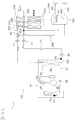
- FIG.1 shows a schematic diagram of a space heating and water supply system 1 including the apparatus 100 as an embodiment of the apparatus for space heating and warm water supply according to the present invention.
- the space heating and water supply system 1 is used for space heating and warm water supply in a residential building.
- the space heating and water supply system 1 may be used in another type of building.
- the space heating and water supply system 1 includes the apparatus 100, a space heating unit 200, and a water supply unit 300.
- the apparatus 100 heats a heating medium which is used for space heating and heating domestic water.
- the apparatus 100 has a heat pump unit 20 as a heat source to heat the heating medium as shown in FIG.1 .
- the heating medium is an aqueous medium.
- the type of heating medium is given here by way of example, and not by way of limitation.
- the apparatus 100 can supply the heating medium heated by the heat pump unit 20 to the space heating unit 200 and the water supply unit 300.
- the apparatus 100 can receive the heating medium returned from the space heating unit 200 or the water supply unit 300.
- the apparatus 100 has an outlet 12 of the heating medium through which the heating medium flows out toward the space heating unit 200 or the water supply unit 300.
- the apparatus 100 has an inlet 14 of the heating medium through which the heating medium retuned from the space heating unit 200 or the water supply unit 300 flows in.
- the configuration of the apparatus 100 will be explained in detail later.
- the space heating unit 200 includes at least one heat emitter 230 such as a floor heating.
- the space heating unit 200 includes a plurality of heat emitters 230.
- the type of the heat emitter 230 is not limited to the floor heating.
- the heat emitter 230 may be a radiator or a convector.
- Each of the heat emitters 230 is located in a space to be heated.
- the space heating unit 200 further includes an inlet header 210, an outlet header 220, and at least one valve 240.
- the inlet header 210 is connected to the outlet 12 of the apparatus 100 by piping.
- the outlet header 220 is connected to the inlet 14 of the apparatus 100 by piping.
- Each of the heat emitter 230 is connected to both of the inlet header 210 and the outlet header 220 by piping.
- the piping is configured such that the heating medium can flow in the heat emitter 230 from the inlet header 210 to the outlet header 220 through the piping.
- a valve 240 is arranged on the piping between the inlet header 210 and each of the heat emitters 230 or on the piping between each of the heat emitters 230 and the outlet header 220.
- the space heating unit 200 further includes at least one thermostat (not shown) with a temperature sensor (not shown) for measuring the temperature in the space to be heated by the space heating unit 200. A user of the space heating unit 200 may set a target room temperature to the thermostat.
- the thermostat sends a signal to the apparatus 100 for requesting an operation of the apparatus 100 in a space heating mode based on the user's command and the temperature detected by the temperature sensor.
- the thermostat controls the operation of the valves 240 based on the target room temperature and the temperature detected by the temperature sensor. In a case that a part of the valves 240 are closed, the volume of the heating medium circulating in the space heating circuit 250 is reduced compared with a case that all of the valves 240 are opened.
- the apparatus 100 is connected to a space heating unit 200 so as to form a space heating circuit 250 in which the heating medium is circulated.
- the outlet 12 of the heating medium of the apparatus 100 is connected to the inlet header 210 of the space heating unit 200 by piping.
- the inlet 14 of the heating medium of the apparatus 100 is connected to the outlet header 220 of the space heating unit 200 by piping.
- the space heating circuit 250 is formed.
- the apparatus 100 is operated in the space heating mode during which the space heating circuit 250 is activated and the heat pump unit 20 is operated in a heating mode described later, the heating medium heated with the heat pump unit 20 is supplied to the space heating unit 200 in the space heating circuit 250.
- the space heating circuit is configured such that the heating medium having been used for space heating at the space heating unit 200 returns to the apparatus 100 in the space heating circuit 250 after having radiated its heat at the heat emitter 230.
- the space heating unit 300 includes a water tank 310 and a heat exchange part 320.
- An inlet pipe 330 of the domestic water and an outlet pipe 340 of the domestic water are connected to the water tank 310.
- Domestic water is supplied to the water tank 310 through the inlet pipe 330 of the domestic water.
- domestic water is stored in the water tank 310.
- the heat exchange part 320 is arranged in the water tank 310.
- the heat exchange part 320 has an inlet and an outlet of the heating medium.
- the inlet of the heat exchange part 320 is connected to outlet 12 of the heating medium of the apparatus 100 by piping.
- the outlet of the heat exchange part 320 is connected to inlet 14 of the heating medium of the apparatus 100 by piping.
- the water supply unit 300 further includes a controller (not shown) with a temperature sensor (not shown) for measuring the temperature of the water in the water tank 310.
- a user of the water supply unit 300 may set a target water temperature to the controller.
- the controller sends a signal to the apparatus 100 for requesting an operation of the apparatus 100 in a water supply mode based on the target water temperature and the temperature detected by the temperature sensor.
- the apparatus 100 is connected to a water supply unit 300 having a water tank 310 so as to form a water supply circuit 350 in which the heating medium circulates.
- the outlet 12 of the heating medium of the apparatus 100 is connected to the inlet of the heat exchange part 320 by piping.
- the inlet 14 of the heating medium of the apparatus 100 is connected to the outlet of the heat exchange part 320 by piping.
- the water supply circuit 350 is formed.
- Both of the space heating circuit 250 and the water supply circuit 350 utilize piping which is arranged on the downstream of the converging point 400 of the space heating circuit 250 and the water supply circuit 350 and on the upstream of the circuit switching means 40 with respect to the flow direction of the heating medium.
- both of the space heating circuit 250 and the water supply circuit 350 utilize piping which connects the outlet for the heating medium of the second heat exchanger 26 and the inlet for the heating medium of the circuit switching means 40 and piping which connects the converging point 400 of the space heating circuit 250 and the water supply circuit 350 and the inlet for the heating medium of the second heat exchanger 26 as shown in FIG.1 .
- the piping commonly utilized by the space heating circuit 250 and the water supply circuit 350 is referred to as common piping.
- the apparatus 100 for space heating and water supply is mainly provided with piping 10, the heat pump unit 20, a first heat exchanger temperature sensor 30, a circuit switching means 40, a return medium temperature sensor 60, an electrical heating means 70, and a pump 80.
- the apparatus 100 is further provided with a controller 90.
- the piping 10 constitutes a part of the space heating circuit 250 and the water supply circuit 350.
- the piping 10 connects the inlet 14 of the heating medium, the pump 80, a second heat exchanger 26 of the heat pump unit 20, and the outlet 12 of the heating medium.
- the heating medium flows as follows.
- the heating medium flowing into the inlet 14 of the heating medium is sucked into the pump 80 through the piping 10.
- the pump 80 delivers the heating medium toward the second heat exchanger 26 of the heat pump unit 20 through the piping 10.
- the heating medium passing through the second heat exchanger 26 of the heat pump unit 20 flows through the piping 10 toward the outlet 12 of the heating medium.
- the heating medium then flows out from the outlet 12 of the heating medium toward the space heating unit 200 or the water supply unit 300.
- the heat pump unit 20 is configured to heat the heating medium flowing in the space heating circuit 250 or the water supply circuit 350.
- the heat pump unit 20 is driven by electricity.
- the heat pump unit 20 includes a conventional refrigerant circuit 21 in which a compressor 22, a flow direction switching mechanism 23, the second heat exchanger 26, an expansion mechanism 28 and a first heat exchanger 24 is connected by the piping 10.
- the refrigerant is, for example, R-410A or another HFC-based refrigerant circulates.
- the type of refrigerant is given here by way of example, and not by way of limitation.
- the compressor 22 is a mechanism to compress the refrigerant.
- a motor (not shown) of the compressor 22 may be driven at variable frequency so that the heat pump unit 20 may be driven under full load but also under a partial load.
- the frequency of the motor of the compressor 22 may be decided, for example, based on the ambient temperature around the heat pump unit 20 detected by an ambient temperature sensor (not shown).
- the motor (not shown) of the compressor 22 may be driven at constant frequency when the operation mode of the heat pump unit 20 is set to the heating mode, although it is preferable that motor of the compressor 22 is driven at variable frequency.
- the frequency of the motor of the compressor 22 may be set to a predetermined frequency, for example.
- the flow direction switching mechanism 23 is configured to switch a flow direction of the refrigerant between a first direction and a second direction in the refrigerant circuit 21.
- the refrigerant compressed by the compressor 22 flows through the flow direction switching mechanism 23, the second heat exchanger 26, the expansion mechanism 28, the first heat exchanger 24 in this order and returns to a suction side of the compressor 22 (see an arrow A1 and solid line in the flow direction switching mechanism 23 in FIG.1 ).
- the refrigerant compressed by the compressor 22 flows through the flow direction switching mechanism 23, the first heat exchanger 24, the expansion mechanism 28, and the second heat exchanger 26 in this order and returns the suction side of to the compressor 22 (see an arrow A2 and dashed line in the flow direction switching mechanism 23 in FIG.1 ).
- the second heat exchanger 26 works as a condenser and the first heat exchanger 24 works as an evaporator.
- the first heat exchanger 24 works as a condenser and the second heat exchanger 26 works as an evaporator.
- the flow direction switching mechanism 23 is a four-way switching valve configured to switch the flow direction of the refrigerant between the first direction and the second direction in the refrigerant circuit 21.
- the flow direction switching mechanism 23 is not limited to a four-way switching valve.
- the flow direction switching mechanism 23 may be configured by combining a plurality of electromagnetic valves, so as to have the function of switching the refrigerant flow direction in the same manner as described above.
- the first heat exchanger 24 is configured such that the refrigerant exchanges heat with ambient air passing through the first heat exchanger 24.
- the first heat exchanger 24 works as an evaporator of the refrigerant and the second heat exchanger 26 works as a condenser of the refrigerant.
- the heating medium passing through the second heat exchanger 26 is heated up by the refrigerant flowing in the refrigerant circuit 21.
- the flow direction mechanism 23 connects the piping of the heat pump unit 20 such that the refrigerant flows along the first direction in the refrigerant circuit 21.
- the first heat exchanger 24 works as a condenser of the refrigerant and the second heat exchanger 26 works as an evaporator of the refrigerant.
- the flow direction mechanism 23 connects the piping of the heat pump unit 20 such that the refrigerant flows along the second direction in the refrigerant circuit 21.
- the refrigerant passes through the second heat exchanger 26 to be heated up by the heating medium flowing in the space heating circuit 250 or the water supply circuit 350, and the heated refrigerant further flows to the heat exchanger 24.
- the heat of the refrigerant flowing through the first heat exchanger 24 is transferred to a surface of the first heat exchanger 24 so that the first heat exchanger 24 is defrosted.
- the expansion mechanism 28 is an electric expansion valve which depressurizes refrigerant flowing in the refrigerant circuit 21.
- the second heat exchanger 26 is configured such that the heating medium circulating in the space heating circuit 250 or in the water supply circuit 350 exchanges heat with the refrigerant circulating in the refrigerant circuit 21.
- the second heat exchanger 26 functions as a condenser of the refrigerant flowing in the first direction.
- the second heat exchanger 26 functions as an evaporator of the refrigerant flowing in the second direction.
- the first heat exchanger temperature sensor 30 is configured to detect a temperature of the refrigerant flowing through the first heat exchanger 24.
- the first heat exchanger temperature sensor 30 is preferably arranged on the first heat exchanger 24.
- the circuit switching means 40 is configured to switch a flow circuit of the heating medium between the space heating circuit 250 and the water supply circuit 350.
- the circuit switching means 40 selectively connects the outlet 12 of the heating medium of the apparatus 100 to the inlet header 210 of the space heating unit 200 or the inlet of the heat exchange part 320 of the water supply unit 300.
- the circuit switching means 40 may be arranged on the piping between the inlet 14 of the heating medium of the apparatus 100 and the outlet header 220 of the space heating unit 200 and between the inlet 14 of the heating medium of the apparatus 100 and the outlet of the heat exchange part 320 of the water supply unit 300.
- the outlet 12 of the heating medium of the apparatus 100 may be connected to the inlet header 210 of the space heating unit 200 and the inlet of the heat exchange part 320 of the water supply unit 300 by piping.
- the circuit switching means 40 is, for example, an electric or solenoid three-way valve arranged on the piping as shown in FIG.1 .
- the circuit switching means 40 may be configured by a plurality of electric or solenoid valves arranged on the piping.
- the return medium temperature sensor 60 is configured to detect a temperature of the heating medium which has returned to the apparatus 100 after circulating in the space heating unit 200 or the water supply unit 300.
- the return medium temperature sensor 60 is arranged on or in a pipe 10a which constitutes a part of the piping 10.
- the return medium temperature sensor 60 is arranged on the upstream side of both of the heat pump unit 20, and on the downstream side of both of the space heating unit 200 and the water supply unit 300 with respect to a flow direction of the heating medium.
- the return medium temperature sensor 60 is arranged at a location on or in the piping 10 between the inlet 14 of the heating medium and the second heat exchanger 26 of the heat pump unit 20.
- the return medium temperature sensor 60 is located immediately before the first heat exchanger 24 with respect to the flow direction of the heating medium.
- the electrical heating means 70 is arranged in or on the water tank 310.
- the electrical heating means 70 is configured to heat the water in the water tank 310.
- the pump 80 is arranged on the piping 10 to circulate the heating medium in the space heating circuit 250 or the water supply circuit 350.
- the pump 80 is arranged on the upstream side of the heat pump unit 20 with respect to a flow direction of the heating medium.
- the pump 80 may be arranged on the downstream side of the heat pump unit 20 with respect to a flow direction of the heating medium.
- the controller 90 controls the operation of the apparatus 100.
- the controller 90 includes a microcomputer and a memory (not shown).
- the microcomputer executes programs stored in the memory, whereby the controller 90 controls the operation of the components of the apparatus 100 based on the signals received from the space heating unit 200 and the water supply unit 300 and the detection results from the sensors including the first heat exchanger temperature sensor 30 and the return medium temperature sensor 60.
- the controller 90 is electrically connected to the heat pump unit 20, the first heat exchanger temperature sensor 30, the circuit switching means 40, the return medium temperature sensor 60, the electrical heating means 70, and the pump 80 as shown in FIG.2 .
- the controller 90 is also electrically connected with the thermostat of the space heating unit 200 and the controller of the water supply unit 300 to exchange signals.
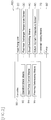
- the controller 90 includes an operation mode means 92, a heat pump control means 94, and a freezing determining means 96 as function sections as shown in FIG.2 .
- the operation mode means 92 is configured to switch the operation mode of the apparatus 100 between the space heating mode and the water supply mode by controlling the circuit switching means 40.
- the space heating circuit 250 is activated during the space heating mode.
- the circuit switching means 40 is controlled to connect the outlet 12 of the heating medium of the apparatus 100 to the inlet header 210. Thereby the heating medium circulates in the space heating circuit 250.
- the water supply circuit 350 is activated during the water supply mode.
- the circuit switching means 40 is controlled to connect the outlet 12 of the heating medium of the apparatus 100 to the inlet of the heat exchange part 320. Thereby, the heating medium circulates in the water supply circuit 350.
- the operation mode of the apparatus 100 to which the operation mode means 92 switches is determined based on the signals sent from the space heating unit 200 and/or the water supply unit 300.
- the operation mode of the apparatus 100 to which the operation mode means 92 switches is determined further based on the other factors. It will be explained later how the operation mode means 92 determines the operation mode of the apparatus 100.
- the heat pump control means 94 controls the operation of the heat pump unit 20.
- the heat pump control means 94 controls various elements of the heat pump unit 20, such as the compressor 22 (the mortar of the compressor 22), the flow direction switching mechanism 23, and the expansion mechanism 28.
- the heat pump control means 94 controls various elements of the heat pump unit 20 according to the signals received from the space heating unit 200 and/or the water supply unit 300 and the detection results from the sensors including the first heat exchanger temperature sensor 30 and the return medium temperature sensor 60.
- the heat pump control means 94 sets the operation mode of the heat pump unit 20.
- the heat pump unit 20 has at least a heating mode and a defrosting mode as operation modes.
- the heat pump control means 94 sets the operation mode of the heat pump unit 20 to the heating mode
- the heat pump control means 94 sets the flow direction of the refrigerant in the refrigerant circuit 21 to the first direction by controlling the flow direction switching mechanism 23.
- the heat pump control means 94 sets the operation mode of the heat pump unit 20 to the defrosting mode
- the heat pump control means 94 sets the flow direction of the refrigerant in the refrigerant circuit 21 to the second direction by controlling the flow direction switching mechanism 23.
- heat pump control means 94 determines the operation mode of the heat pump unit 20.
- the determining means 96 determines, during the operation in the defrosting mode of the heat pump unit 20 and during the operation of the space heating mode or the water supply mode of the apparatus 100, whether the heating medium can freeze at the second heat exchanger 26. Preferably, the determining means 96 determines whether the heating medium can freeze at the second heat exchanger 26 based on the temperature of the heating medium detected by the return medium temperature sensor 60. Specifically, the determining means 96 determines that the heating medium can freeze at the second heat exchanger 26 in a case when the temperature of the heating medium detected by the return medium temperature sensor 60 is lower than a predetermined temperature Tf.
- the operation mode means 92 sets the operation mode of the apparatus 100 to the space heating mode
- the heat pump control means 94 sets the operation mode of the heat pump unit 20 to the heating mode prior to step S1.
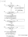
- the heat pump control means 94 determines whether the defrosting operation is necessary for the heat pump unit 20 based on the temperature detected by the first heat exchanger temperature sensor 30. If yes, the process advances to step S2.
- the heat pump control means 94 determines "yes" when the temperature detected by the first heat exchanger temperature sensor 30 is lower than a first predetermined temperature T1.
- the first predetermined temperature T1 is predetermined so that the defrosting operation is performed at a proper timing.
- the step S1 is repeated until the heat pump control means 94 determines "yes.”
- the heat pump control means 94 sets the operation mode of the heat pump unit 20 to the defrosting mode.
- the heat pump control means 94 determines whether the defrosting operation of the heat pump unit 20 has been completed based on the temperature detected by the first heat exchanger temperature sensor 30. If no, the process advances to step S4. Otherwise, the process advances to step S20.
- the heat pump control means 94 determines "yes" when the temperature detected by the first heat exchanger temperature sensor 30 is higher than a second predetermined temperature T2.
- the second predetermined temperature T2 is predetermined so that the heat pump unit 20 can return the heating operation at a proper timing.
- the second predetermined temperature T2 is higher than the first predetermined temperature T1.
- the heat pump control means 94 sets the operation mode of the heat pump unit 20 to the heating mode.
- the freezing determining means 96 determines, during the operation in the defrosting mode of the heat pump unit 20 and during the operation of the space heating mode of the apparatus 100, whether the heating medium can freeze at the second heat exchanger 26. If yes, the process advances to the step S5. Otherwise, the process returns to the step S3. The determination is made based on the temperature of the heating medium detected by the return medium temperature sensor 60. The freezing determining means 96 determines that the heating medium can freeze at the second heat exchanger 26 when the temperature detected by the return medium temperature sensor 60 is lower than the predetermined temperature Tf.
- the operation mode means 92 preserves, in accordance with the determination of the freezing determining means 96 at the step S4, the apparatus 100 in the space heating mode prior to the step S9 for setting the operation mode of the apparatus 100 to the water supply mode as mentioned below.
- the heat pump control means 94 switches the operation mode of the heat pump unit 20 from the defrosting mode to the heating mode.
- a predetermined time t1
- a predetermined time is, for example, 10 minutes. If yes, the process advances to step S8.
- the step S7 is repeated until the heat pump control means 94 determines "yes.”
- the process proceeds to step S8 based on the determination, in step S7, whether a predetermined time (t1) has elapsed since the heat pump control means 94 switched the operation mode of the heat pump unit 20 from the defrosting mode to the heating mode at step S6.
- a predetermined time (t1) it may be determined whether the process proceeds to step S8 based on other conditions.
- the process may proceed to step S8 based on the temperature detected by the first heat exchanger temperature sensor 30.
- the process may proceed to step S8 when the temperature detected by the first heat exchanger temperature sensor 30 is lower than a first predetermined temperature T1.
- the heat pump control means 94 sets the operation mode of the heat pump unit 20 to the defrosting mode.
- the operation mode means 92 sets the operation mode of the apparatus 100 to the water supply mode. In other words, at the step S9, during the operation in the defrosting mode of the heat pump unit 20, the operation mode means 92 switches the operation mode of the apparatus 100 from the space heating mode to the water supply mode.
- the step S8 is executed before the step S9.
- the step S9 may be executed at the same time or just before the step S8.
- the phrase "the operation mode means 92 sets/switches the operation mode of the apparatus 100 to the water supply mode during the operation in the defrosting mode of the heat pump unit 20" includes a case when the operation mode means 92 sets the operation mode of the apparatus 100 to the water supply mode at the same time when or just before the heat pump control means 94 sets the operation mode of the heat pump unit 20 to the defrosting mode.
- the heat pump control means 94 switches the operation mode of the heat pump unit 20 from the defrosting mode to the heating mode in step S6 while preserving the operation mode of the apparatus 100 in the space heating mode in prior to operating the heat pump unit 20 in the defrosting mode during the water supply mode of the apparatus 100. This is because the following reasons.
- the freezing determining means 96 determines that the heating medium can freeze at the second heat exchanger 26 in step S4
- the temperature of the heating medium flowing in the space heating circuit 250 is relatively low.
- the temperature of the heating medium in the common piping which is arranged on the downstream of the converging point 400 of the space heating circuit 250 and the water supply circuit 350 and on the upstream of the circuit switching means 40 with respect to the flow direction of the heating medium and constitutes a part of the space heating circuit 250, is also relatively low. Therefore, if steps S5 to S8 are omitted and the operating mode of the apparatus 100 is switched to the water supply mode while preserving the operating mode of heat pump unit 20 in the defrosting mode, the heat of the heating medium in the common piping is scarcely used for defrosting.
- the heat pump unit 20 in the heating mode in order to heat the heating medium flowing in the space heating circuit 250 prior to operating the heat pump unit 20 in the defrosting mode during the water supply mode of the apparatus 100, the heat of the heating medium in the common piping can be also used for defrosting. Therefore, it is possible to complete the defrosting in a short time.
- the heat pump control means 94 determines whether the defrosting operation of the heat pump unit 20 has been completed based on the temperature detected by the first heat exchanger temperature sensor 30. The determination is made the same as at the step S3. When the heat pump control means 94 determines "no", the process advances to step S11. Otherwise, the process advances to the step S30.
- the operation mode means 92 sets the operation mode of the apparatus 100 to the space heating mode.
- the heat pump control means 94 sets the operation mode of the heat pump unit 20 to the heating mode.
- step S30 is executed prior to the step S31 in the flow chart above, the step S31 may be executed at the same time or just before the step S30.
- the freezing determining means 96 determines, during the operation in the defrosting mode of the heat pump unit 20 and during the operation of the water supply mode of the apparatus 100, whether the heating medium can freeze at the second heat exchanger 26. This determination is made based on the temperature of the heating medium detected by the return medium temperature sensor 60.
- the freezing determining means 96 determines "yes" when the temperature detected by the return medium temperature sensor 60 is lower than the predetermined temperature Tf. If yes, the process advances to the step S12. Otherwise, the process returns to the step S10.
- the predetermined temperature Tf used in step S11 is equal to the predetermined temperature Tf used in step S4.
- the predetermined temperature Tf used in step S11 may be different from the predetermined temperature Tf used in step S4.
- the predetermined temperatures Tf used in step S4 and/or step S11 may be changed according to the flow rate of the heating medium flowing through the piping 10 detected by a flow sensor (not shown).
- the electrical heating means 70 is activated during the operation of the apparatus 100 in the water supply mode.
- the heat pump control means 94 suspends the operation of the heat pump unit 20 in accordance with the activation of the electrical heating means 70.
- the step S12 is executed before the step S13 in the flow chart above. However, the step S13 may be executed at the same time or just before the step S12.
- the phrase "the heat pump control means 94 suspends the operation of the heat pump unit 20 in accordance with the activation of the electrical heating means 70" includes a case when the heat pump control means 94 suspends the operation of the heat pump unit 20 at the same time when or just before the electrical heating means 70 is activated.
- step S14 it is determined whether a predetermined time (t2) has elapsed since the heat pump control means 94 suspends the operation of the heat pump unit 20 in accordance with the activation of the electrical heating means 70 at the step S13.
- the predetermined time (t2) is determined so that the temperature of the heating medium circulating in the water supply circuit becomes high enough to achieve the defrosting. If "yes”, the process advances to step S15. The step S14 is repeated until the determination result becomes "yes.”
- the heat pump control means 94 restarts the operation of the heat pump unit 20 in the defrosting mode.
- the heat pump control means 94 determines whether the defrosting operation of the heat pump unit 20 has been completed based on the temperature detected by the first heat exchanger temperature sensor 30. This determination is made the same as at the step S10. The heat pump control means 94 determines "yes" when temperature detected by the first heat exchanger temperature sensor 30 is larger than the second predetermined temperature T2. If "yes,” the process advances to step S17. The step S16 is repeated until the heat pump control means 94 determines "yes.”
- the electrical heating means 70 is turned off.
- the operation mode means 92 sets the operation mode of the apparatus 100 to the space heating mode.
- the heat pump control means 94 sets the operation mode of the heat pump unit 20 to the heating mode.
- the order of the steps S17 to S19 in FIG. 3b is an example of the process.
- the order of the steps S17 to S19 may be changed as needed.
- the operation mode means 92 sets the operation mode of the apparatus 100 to the water supply mode
- the heat pump control means 94 sets the operation mode of the heat pump unit 20 to the heating mode prior to step S101.
- the heat pump control means 94 determines whether the defrosting operation of the heat pump unit 20 is necessary based on the temperature detected by the first heat exchanger temperature sensor 30. The determination is made the same as at the step S1 mentioned above.
- the heat pump control means 94 determines "yes" when temperature detected by the first heat exchanger temperature sensor 30 is lower than the first predetermined temperature T1. If "yes,” the process advances to step S102. The step S101 is repeated until the heat pump control means 94 determines "yes.”
- the heat pump control means 94 sets the operation mode of the heat pump unit 20 to the defrosting mode.
- the heat pump control means 94 determines whether the defrosting operation of the heat pump unit 20 has been completed based on the temperature detected by the first heat exchanger temperature sensor 30. The determination is made the same as at the step S10 mentioned above.
- the heat pump control means 94 determines "no" when the temperature detected by the first heat exchanger temperature sensor 30 is equal to or lower than the second predetermined temperature T2. If "no," the process advances to the step S111. Otherwise, the process advances to the step S131.
- the heat pump control means 94 sets the operation mode of the heat pump unit 20 to the heating mode.
- the freezing determining means 96 determines whether the heating medium can freeze at the second heat exchanger 26 based on the temperature of the heating medium detected by the return medium temperature sensor 60. The determination is made the same as at the step S11. The freezing determining means 96 determines "yes" when the temperature detected by the return medium temperature sensor 60 is lower than the predetermined temperature Tf. If "yes", the process advances to the step S111. Otherwise, the process returns to the step S110.
- the steps S112 to S117 and the step S119 are the same as the steps S12 to S17 and the step S19 described above, therefore the explanation of these steps is omitted.
- a step corresponding to the step S18 in FIG.3b does not exist. In other words, there is no step to set the operation mode of the apparatus 100 to the space heating mode. This is because the apparatus 100 starts the water supply operation after the defrosting operation of the heat pump unit 20 has been completed.
- an additional heat source unit is attached to the water supply circuit 300 to heat at least the heating medium circulating in the water supply circuit 300.
- the additional heat source unit may include a heat exchanger and a burner.
- the heat exchanger is preferably arranged in series with the second heat exchanger 26 in the water supply circuit 300.
- the burner is configured to heat the heating medium flowing through the second heat exchanger 26.
- the burner has substantially the same function as the electrical heating means 70. By activating the burner at step S12 in FIG.3b and at step S112 in FIG.4 instead of turning on the electrical heating means 70, it is possible to heat the water in the water tank 310.
Landscapes
- Engineering & Computer Science (AREA)
- Physics & Mathematics (AREA)
- Thermal Sciences (AREA)
- Chemical & Material Sciences (AREA)
- Combustion & Propulsion (AREA)
- Mechanical Engineering (AREA)
- General Engineering & Computer Science (AREA)
- Water Supply & Treatment (AREA)
- Steam Or Hot-Water Central Heating Systems (AREA)
- Heat-Pump Type And Storage Water Heaters (AREA)
Abstract
Description
- The invention relates to an apparatus for space heating and water supply, specifically an apparatus for space heating and water supply having a heat pump as a heat source.
- Such an apparatus is known from
EP 2 530 406 A1 - The apparatus above improves efficiency by using the heat pump unit as a heat source instead of using the conventional boiler such as fuel-fired boiler since heat pump units generally have better energy efficiency than conventional boilers.
- The heat pump unit has a heat-source-side heat exchange means and a usage-side heat exchange means. A refrigerant circulates between the heat-source-side heat exchange means and the usage-side heat exchange means. At the heat-source-side heat exchange means, the refrigerant exchanges heat with the ambient air. At the usage-side heat exchange means, the refrigerant exchanges heat with the heating medium. When the heat pump unit heats the heating medium for space heating or water supply, the heat-source-side heat exchange means works as an evaporator and the usage-side heat exchange means works as a condenser.
- During heating the heating medium, the surface of the heat-source-side heat exchange means obtains frost under a certain operating condition and thereby the efficiency of the heat pump unit may be deteriorated. In such a case, reversed cycle defrosting operation may be performed for defrosting. During the reversed cycle defrosting operation, the heat-source-side heat exchange means works as a condenser and the usage-side heat exchange means works as an evaporator. The reversed cycle defrosting operation is performed while circulating the heating medium. This is because the heating medium may freeze at the usage-side heat exchange means working as an evaporator.
- Even when the heating medium circulates during the reversed cycle defrosting operation, there is a risk that the heating medium freezes at the usage-side heat exchange means if the total amount of the circulating heating medium is relatively small. Especially, the heating medium likely to freeze during the space heating since the total amount of the circulating heating medium often decreases depending on the operation load for the space heating.
- To avoid such a risk, it is required to secure a certain amount of the heating medium circulating in the space heating circuit. On the other hand, less and less amount of heating medium is needed for high-sealed rooms/houses and the requirement for energy efficiency of space heating.
- It is the object of the present invention to provide an apparatus for space heating and water supply having a heat pump unit and having high efficiency of the apparatus while relaxing the minimum limitation of the total amount of heating medium in the space heating circuit.
- A first aspect of the present invention provides an apparatus configured to be connected to a space heating unit and a water supply unit with a water tank so as to form a space heating circuit and a water supply circuit in which a heating medium is supplied to the space heating unit and the water supply unit, respectively. The apparatus is provided with a heat pump unit, a circuit switching means, an operation mode means and a heat pump control means. The heat pump unit has a compressor, a first heat exchange means, and a second heat exchange means. The compressor is configured to compress a refrigerant. The first heat exchange means is configured such that the refrigerant exchanges with ambient air therein. The second heat exchange means is configured such that the refrigerant exchanges heat with the heating medium. The circuit switching means is configured to switch a flow circuit of the heating medium between the space heating circuit and the water supply circuit. The operation mode means is configured to set an operation mode of the apparatus to a space heating mode or a water supply mode by controlling the circuit switching means such that the space heating circuit is activated during the space heating mode and the water supply circuit is activated during the water supply mode. The heat pump control means is configured to set an operation mode of the heat pump unit to a heating mode or a defrosting mode. During the heating mode, the first heat exchange means works as an evaporator and the second heat exchange means working as a condenser. During the defrosting mode, the first heat exchange means works as a condenser and the second heat exchange means works as an evaporator. During the operation in the defrosting mode of the heat pump unit and during the operation of the space heating mode of the apparatus, the operation mode means is configured to switch the operation mode of the apparatus from the space heating mode to the water supply mode.
- With the above configuration, it is possible to perform the defrosting mode with the heat of the heating medium circulating in the water supply circuit, even if the amount of heat of the heating medium circulating in the space heating circuit is not enough to complete the defrosting. Therefore, the defrosting can be completed in a short time while relaxing the minimum amount of the heating medium in the heating circuit.
- According to a preferred embodiment of the apparatus mentioned above, the apparatus is further provided with a first determining means. The first determining means is configured to determine, during the operation in the defrosting mode of the heat pump unit and during the operation of the space heating mode of the apparatus, whether the heating medium can freeze at the second heat exchange means. In accordance with the determination of the first determining means, the operation mode means is configured to switch the operation mode of the apparatus from the space heating mode to the water supply mode during the operation in the defrosting mode of the heat pump unit.
- With the above preferred embodiment of the apparatus mentioned above, the heat is not always taken away from the water supply circuit during the operation in the defrosting mode. When it is possible to finish the defrosting operation using the heat of the space heating circuit during the operation of the space heating mode of the apparatus, the heat of the water supply circuit is not used for defrosting operation. Therefore, it is possible to avoid a situation where it takes a long time after the apparatus starts the water supply operation until the temperature of the water in the tank reaches a target temperature due to a significant drop of the temperature of the water in the tank.
- According to another preferred embodiment of the apparatus having the first determining means mentioned above, the operation mode means is configured to preserve, in accordance with the determination of the first determining means, the operation mode of the apparatus at the space heating mode prior to setting the operation mode of the apparatus to the water supply mode. In accordance with the determination of the first determining means and preservation of the operation mode of the apparatus at the space heating supply mode, the heat pump control means is configured to switch the operation mode of the heat pump unit from the defrosting mode to the heating mode. In accordance with the switching of the operation mode of the heat pump unit from the heating mode to the defrosting mode, the operation mode means is configured to set the operation mode of the apparatus to the water supply mode.
- In the above preferred embodiment, the heat pump control means temporarily returns operation mode of the heat pump unit to the heating mode while the operation mode means preserving the operation mode of the apparatus at the space heating mode, in a case where the apparatus cannot continue defrosting during the operation of the space heating mode of the apparatus due to the low temperature of the heating medium. Therefore, it is possible to avoid a situation that the space heating is suspended for a long time.
- Furthermore, in the above embodiment, the operation mode means sets the operation mode of the apparatus to the water supply mode when the defrosting mode is set after the defrosting mode is once discontinued due to the low temperature of the heating medium.
- Therefore, the defrosting can be completed by utilizing the heat of the heating medium circulating in the water supply circuit in a shorter time than repeating the switching of the operation mode of the heat pump unit between the heating mode and the defrosting mode, while relaxing the limitation to the minimum amount of the heating medium in the space heating circuit.
- According to another preferred embodiment of the apparatus having the first determining means mentioned above, the operation mode means is configured to switch the operation mode of the apparatus from the space heating mode to the water supply mode in accordance with the determination of the first determining means. The heat pump control means is configured to preserve the operation mode of the heat pump unit at the defrosting mode in accordance with the determination of the first determining means.
- With the above preferred embodiment of the apparatus mentioned above, it is possible to complete the defrosting in a short time since the defrosting mode is maintained with the aid of the heat of the heating medium circulating in the water supply circuit even if the amount of the heating medium circulating in the space heating circuit is not enough to complete the defrosting.
- According to another preferred embodiment of the apparatus having the first determining means mentioned above, the apparatus is further comprised with a detecting means. The detecting means is arranged on upstream side of the second heat exchange means and on downstream side of the space heating unit and the water supply unit with respect to a flow direction of the heating medium. The detecting means is configured to detect temperature of the heating medium. The first determining means is configured to determine whether the heating medium can freeze at the second heat exchange means based on the temperature of the heating medium detected by the detecting means.
- With this preferred embodiment of any one of the apparatus mentioned-above, it is possible to precisely determine whether the heating medium can freeze at the second heat exchange means.
- According to another preferred embodiment of the apparatus mentioned above, the apparatus is further provided with an electrical heating means and a second determining means. The electrical heating means is arranged in or on the water tank. The electrical heating means is configured to heat the water in the water tank. The second determining means is configured to determine, during the operation in the defrosting mode of the heat pump unit and during the operation of the water supply mode of the apparatus, whether the heating medium can freeze at the second heat exchange means. In accordance with the determination of the second determining means, the electrical heating means is activated during the operation of the apparatus in the water supply mode.
- With this preferred embodiment of any one of the apparatus mentioned-above, it is possible to complete the defrosting even if the temperature of the heating medium circulating in the water supply circuit is not high enough to achieve the defrosting.
- Further, the usage of the electrical heating means can make up for the heat of the water in the tank which is lost during the operation in the defrosting mode. Thus, the temperature of the water in the tank can be maintained or at least the temperature drop of the water in the tank can be suppressed. In an embodiment, the temperature of the water in the tank can be raised with the heat supplied from the electrical heating means.
- According to another preferred embodiment of the apparatus having the electrical heating means and the second determining means mentioned above, the heat pump control means is further configured to suspend the operation of the heat pump unit for a predetermined time in accordance with the activation of the electrical heating means.
- With this preferred embodiment of the apparatus with the electrical heating means, defrosting operation of the heat pump unit is suspended for a predetermined time. Preferably the suspension is maintained until the temperature of the heating medium reaches to a temperature high enough for defrosting. During the suspension of defrosting operation of the heat pump unit, heating medium is heated with the electrical heating means. It is therefore possible to avoid the risk that the heating medium freeze at the second heat exchange means in a more secure manner.
-
-
FIG.1 is a schematic diagram of a space heating and water supply system including an apparatus for space heating and warm water supply according to an embodiment of the present invention. -
FIG.2 is a block diagram of the apparatus for space heating and warm water supply according toFIG.1 . -
FIG.3a andFIG.3b show a flow chart schematically representing a defrosting operation of the heat source unit when the apparatus according toFIG. 1 is operated for space heating. -
FIG.4 shows a flow chart schematically representing a defrosting operation of the heat source unit when the apparatus according toFIG. 1 is operated for water supply. -
FIG.5 is an alternative flow chart ofFIG.3a . - Preferred embodiments of the apparatus for space heating and warm water supply according to the present invention will be described with reference to the drawings.
- It should be understood that the detailed explanation are provided merely for the purpose of explanation, and are in no way to be construed as limiting of the present invention. While the present invention will be described with reference to exemplary preferred embodiments, it is understood that the words which have been used herein are words of description and illustration, rather than words of limitation. Changes may be made, within the purview of the appended claims, as presently stated and as amended, without departing from the scope and spirit of the present invention in its aspects. Although the present invention will be described herein with reference to preferred structures, materials and embodiments, the present invention is not intended to be limited to the particulars disclosed herein; rather, the present invention extends to all configurations within the scope of the appended claims.
-
FIG.1 shows a schematic diagram of a space heating andwater supply system 1 including theapparatus 100 as an embodiment of the apparatus for space heating and warm water supply according to the present invention. - For example, the space heating and
water supply system 1 is used for space heating and warm water supply in a residential building. However, the space heating andwater supply system 1 may be used in another type of building. The space heating andwater supply system 1 includes theapparatus 100, aspace heating unit 200, and awater supply unit 300. - The
apparatus 100 heats a heating medium which is used for space heating and heating domestic water. Theapparatus 100 has aheat pump unit 20 as a heat source to heat the heating medium as shown inFIG.1 . For example, the heating medium is an aqueous medium. The type of heating medium is given here by way of example, and not by way of limitation. Theapparatus 100 can supply the heating medium heated by theheat pump unit 20 to thespace heating unit 200 and thewater supply unit 300. Theapparatus 100 can receive the heating medium returned from thespace heating unit 200 or thewater supply unit 300. Theapparatus 100 has anoutlet 12 of the heating medium through which the heating medium flows out toward thespace heating unit 200 or thewater supply unit 300. Theapparatus 100 has aninlet 14 of the heating medium through which the heating medium retuned from thespace heating unit 200 or thewater supply unit 300 flows in. The configuration of theapparatus 100 will be explained in detail later. - The
space heating unit 200 includes at least oneheat emitter 230 such as a floor heating. InFIG.1 thespace heating unit 200 includes a plurality ofheat emitters 230. The type of theheat emitter 230 is not limited to the floor heating. Theheat emitter 230 may be a radiator or a convector. Each of theheat emitters 230 is located in a space to be heated. Thespace heating unit 200 further includes aninlet header 210, anoutlet header 220, and at least onevalve 240. Theinlet header 210 is connected to theoutlet 12 of theapparatus 100 by piping. Theoutlet header 220 is connected to theinlet 14 of theapparatus 100 by piping. Each of theheat emitter 230 is connected to both of theinlet header 210 and theoutlet header 220 by piping. The piping is configured such that the heating medium can flow in theheat emitter 230 from theinlet header 210 to theoutlet header 220 through the piping. In order to control a flow of the heating medium through theheat emitters 230, avalve 240 is arranged on the piping between theinlet header 210 and each of theheat emitters 230 or on the piping between each of theheat emitters 230 and theoutlet header 220. Thespace heating unit 200 further includes at least one thermostat (not shown) with a temperature sensor (not shown) for measuring the temperature in the space to be heated by thespace heating unit 200. A user of thespace heating unit 200 may set a target room temperature to the thermostat. The thermostat sends a signal to theapparatus 100 for requesting an operation of theapparatus 100 in a space heating mode based on the user's command and the temperature detected by the temperature sensor. The thermostat controls the operation of thevalves 240 based on the target room temperature and the temperature detected by the temperature sensor. In a case that a part of thevalves 240 are closed, the volume of the heating medium circulating in thespace heating circuit 250 is reduced compared with a case that all of thevalves 240 are opened. - The
apparatus 100 is connected to aspace heating unit 200 so as to form aspace heating circuit 250 in which the heating medium is circulated. Specifically, theoutlet 12 of the heating medium of theapparatus 100 is connected to theinlet header 210 of thespace heating unit 200 by piping. Theinlet 14 of the heating medium of theapparatus 100 is connected to theoutlet header 220 of thespace heating unit 200 by piping. Thereby, thespace heating circuit 250 is formed. When theapparatus 100 is operated in the space heating mode during which thespace heating circuit 250 is activated and theheat pump unit 20 is operated in a heating mode described later, the heating medium heated with theheat pump unit 20 is supplied to thespace heating unit 200 in thespace heating circuit 250. The space heating circuit is configured such that the heating medium having been used for space heating at thespace heating unit 200 returns to theapparatus 100 in thespace heating circuit 250 after having radiated its heat at theheat emitter 230. - The
space heating unit 300 includes awater tank 310 and aheat exchange part 320. Aninlet pipe 330 of the domestic water and anoutlet pipe 340 of the domestic water are connected to thewater tank 310. Domestic water is supplied to thewater tank 310 through theinlet pipe 330 of the domestic water. Domestic water is stored in thewater tank 310. Theheat exchange part 320 is arranged in thewater tank 310. Theheat exchange part 320 has an inlet and an outlet of the heating medium. The inlet of theheat exchange part 320 is connected tooutlet 12 of the heating medium of theapparatus 100 by piping. The outlet of theheat exchange part 320 is connected toinlet 14 of the heating medium of theapparatus 100 by piping. Domestic water in thewater tank 310 is heated with the heating medium flowing in theheat exchange part 320. Heated domestic water flows out from thewater tank 310 through theoutlet pipe 340 of the domestic water. Thewater supply unit 300 further includes a controller (not shown) with a temperature sensor (not shown) for measuring the temperature of the water in thewater tank 310. A user of thewater supply unit 300 may set a target water temperature to the controller. The controller sends a signal to theapparatus 100 for requesting an operation of theapparatus 100 in a water supply mode based on the target water temperature and the temperature detected by the temperature sensor. - The
apparatus 100 is connected to awater supply unit 300 having awater tank 310 so as to form awater supply circuit 350 in which the heating medium circulates. Specifically, theoutlet 12 of the heating medium of theapparatus 100 is connected to the inlet of theheat exchange part 320 by piping. Theinlet 14 of the heating medium of theapparatus 100 is connected to the outlet of theheat exchange part 320 by piping. Thereby, thewater supply circuit 350 is formed. When theapparatus 100 is operated in the water supply mode during which thewater supply circuit 350 is activated and theheat pump unit 20 is operated in the heating mode, the heating medium heated with theheat pump unit 20 is supplied to thewater supply unit 300 in thewater supply circuit 350. Thewater supply circuit 350 is configured such that the heating medium having been used for heating domestic water at thewater supply unit 300 returns to theapparatus 100 in thewater supply circuit 350 after having radiated its heat at theheat exchange part 320. - Both of the
space heating circuit 250 and thewater supply circuit 350 utilize piping which is arranged on the downstream of the convergingpoint 400 of thespace heating circuit 250 and thewater supply circuit 350 and on the upstream of the circuit switching means 40 with respect to the flow direction of the heating medium. Specifically, both of thespace heating circuit 250 and thewater supply circuit 350 utilize piping which connects the outlet for the heating medium of thesecond heat exchanger 26 and the inlet for the heating medium of the circuit switching means 40 and piping which connects the convergingpoint 400 of thespace heating circuit 250 and thewater supply circuit 350 and the inlet for the heating medium of thesecond heat exchanger 26 as shown inFIG.1 . The piping commonly utilized by thespace heating circuit 250 and thewater supply circuit 350 is referred to as common piping. - As shown in
FIG.1 , theapparatus 100 for space heating and water supply is mainly provided with piping 10, theheat pump unit 20, a first heatexchanger temperature sensor 30, a circuit switching means 40, a returnmedium temperature sensor 60, an electrical heating means 70, and apump 80. As shown inFIG.2 , theapparatus 100 is further provided with acontroller 90. - The piping 10 constitutes a part of the
space heating circuit 250 and thewater supply circuit 350. The piping 10 connects theinlet 14 of the heating medium, thepump 80, asecond heat exchanger 26 of theheat pump unit 20, and theoutlet 12 of the heating medium. Thereby, the heating medium flows as follows. The heating medium flowing into theinlet 14 of the heating medium is sucked into thepump 80 through thepiping 10. Thepump 80 delivers the heating medium toward thesecond heat exchanger 26 of theheat pump unit 20 through thepiping 10. The heating medium passing through thesecond heat exchanger 26 of theheat pump unit 20 flows through the piping 10 toward theoutlet 12 of the heating medium. The heating medium then flows out from theoutlet 12 of the heating medium toward thespace heating unit 200 or thewater supply unit 300. - The
heat pump unit 20 is configured to heat the heating medium flowing in thespace heating circuit 250 or thewater supply circuit 350. Theheat pump unit 20 is driven by electricity. Theheat pump unit 20 includes a conventionalrefrigerant circuit 21 in which acompressor 22, a flowdirection switching mechanism 23, thesecond heat exchanger 26, anexpansion mechanism 28 and afirst heat exchanger 24 is connected by thepiping 10. The refrigerant is, for example, R-410A or another HFC-based refrigerant circulates. The type of refrigerant is given here by way of example, and not by way of limitation. - The
compressor 22 is a mechanism to compress the refrigerant. A motor (not shown) of thecompressor 22 may be driven at variable frequency so that theheat pump unit 20 may be driven under full load but also under a partial load. When the operation mode of theheat pump unit 20 is set to a heating mode, described hereinafter, the frequency of the motor of thecompressor 22 may be decided, for example, based on the ambient temperature around theheat pump unit 20 detected by an ambient temperature sensor (not shown). Alternatively, the motor (not shown) of thecompressor 22 may be driven at constant frequency when the operation mode of theheat pump unit 20 is set to the heating mode, although it is preferable that motor of thecompressor 22 is driven at variable frequency. When the operation mode of theheat pump unit 20 is set to a defrosting mode, described hereinafter, the frequency of the motor of thecompressor 22 may be set to a predetermined frequency, for example. - The flow
direction switching mechanism 23 is configured to switch a flow direction of the refrigerant between a first direction and a second direction in therefrigerant circuit 21. When the refrigerant flows in the first direction in therefrigerant circuit 21, the refrigerant compressed by thecompressor 22 flows through the flowdirection switching mechanism 23, thesecond heat exchanger 26, theexpansion mechanism 28, thefirst heat exchanger 24 in this order and returns to a suction side of the compressor 22 (see an arrow A1 and solid line in the flowdirection switching mechanism 23 inFIG.1 ). When the refrigerant flows in the second direction in therefrigerant circuit 21, the refrigerant compressed by thecompressor 22 flows through the flowdirection switching mechanism 23, thefirst heat exchanger 24, theexpansion mechanism 28, and thesecond heat exchanger 26 in this order and returns the suction side of to the compressor 22 (see an arrow A2 and dashed line in the flowdirection switching mechanism 23 inFIG.1 ). When the refrigerant flows in the first direction in therefrigerant circuit 21, thesecond heat exchanger 26 works as a condenser and thefirst heat exchanger 24 works as an evaporator. When the refrigerant flows in the second direction in therefrigerant circuit 21, thefirst heat exchanger 24 works as a condenser and thesecond heat exchanger 26 works as an evaporator. - In this embodiment, the flow
direction switching mechanism 23 is a four-way switching valve configured to switch the flow direction of the refrigerant between the first direction and the second direction in therefrigerant circuit 21. However, the flowdirection switching mechanism 23 is not limited to a four-way switching valve. For example, the flowdirection switching mechanism 23 may be configured by combining a plurality of electromagnetic valves, so as to have the function of switching the refrigerant flow direction in the same manner as described above. - The
first heat exchanger 24 is configured such that the refrigerant exchanges heat with ambient air passing through thefirst heat exchanger 24. When theheat pump unit 20 operates in a heating mode, thefirst heat exchanger 24 works as an evaporator of the refrigerant and thesecond heat exchanger 26 works as a condenser of the refrigerant. Thereby the heating medium passing through thesecond heat exchanger 26 is heated up by the refrigerant flowing in therefrigerant circuit 21. During the heating mode, theflow direction mechanism 23 connects the piping of theheat pump unit 20 such that the refrigerant flows along the first direction in therefrigerant circuit 21. When theheat pump unit 20 operates in a defrosting mode, thefirst heat exchanger 24 works as a condenser of the refrigerant and thesecond heat exchanger 26 works as an evaporator of the refrigerant. In other words, during the defrosting mode, theflow direction mechanism 23 connects the piping of theheat pump unit 20 such that the refrigerant flows along the second direction in therefrigerant circuit 21. Thereby, the refrigerant passes through thesecond heat exchanger 26 to be heated up by the heating medium flowing in thespace heating circuit 250 or thewater supply circuit 350, and the heated refrigerant further flows to theheat exchanger 24. Then, the heat of the refrigerant flowing through thefirst heat exchanger 24 is transferred to a surface of thefirst heat exchanger 24 so that thefirst heat exchanger 24 is defrosted. - The
expansion mechanism 28 is an electric expansion valve which depressurizes refrigerant flowing in therefrigerant circuit 21. - The
second heat exchanger 26 is configured such that the heating medium circulating in thespace heating circuit 250 or in thewater supply circuit 350 exchanges heat with the refrigerant circulating in therefrigerant circuit 21. When theheat pump unit 20 operates in the heating mode, thesecond heat exchanger 26 functions as a condenser of the refrigerant flowing in the first direction. When theheat pump unit 20 operates in the defrosting mode, thesecond heat exchanger 26 functions as an evaporator of the refrigerant flowing in the second direction. - The first heat
exchanger temperature sensor 30 is configured to detect a temperature of the refrigerant flowing through thefirst heat exchanger 24. The first heatexchanger temperature sensor 30 is preferably arranged on thefirst heat exchanger 24. - The circuit switching means 40 is configured to switch a flow circuit of the heating medium between the
space heating circuit 250 and thewater supply circuit 350. The circuit switching means 40 selectively connects theoutlet 12 of the heating medium of theapparatus 100 to theinlet header 210 of thespace heating unit 200 or the inlet of theheat exchange part 320 of thewater supply unit 300. Alternatively, the circuit switching means 40 may be arranged on the piping between theinlet 14 of the heating medium of theapparatus 100 and theoutlet header 220 of thespace heating unit 200 and between theinlet 14 of the heating medium of theapparatus 100 and the outlet of theheat exchange part 320 of thewater supply unit 300. In this case, theoutlet 12 of the heating medium of theapparatus 100 may be connected to theinlet header 210 of thespace heating unit 200 and the inlet of theheat exchange part 320 of thewater supply unit 300 by piping. The circuit switching means 40 is, for example, an electric or solenoid three-way valve arranged on the piping as shown inFIG.1 . However, the circuit switching means 40 may be configured by a plurality of electric or solenoid valves arranged on the piping. - The return
medium temperature sensor 60 is configured to detect a temperature of the heating medium which has returned to theapparatus 100 after circulating in thespace heating unit 200 or thewater supply unit 300. The returnmedium temperature sensor 60 is arranged on or in apipe 10a which constitutes a part of thepiping 10. The returnmedium temperature sensor 60 is arranged on the upstream side of both of theheat pump unit 20, and on the downstream side of both of thespace heating unit 200 and thewater supply unit 300 with respect to a flow direction of the heating medium. The returnmedium temperature sensor 60 is arranged at a location on or in the piping 10 between theinlet 14 of the heating medium and thesecond heat exchanger 26 of theheat pump unit 20. Preferably, the returnmedium temperature sensor 60 is located immediately before thefirst heat exchanger 24 with respect to the flow direction of the heating medium. - The electrical heating means 70 is arranged in or on the
water tank 310. The electrical heating means 70 is configured to heat the water in thewater tank 310. - The
pump 80 is arranged on the piping 10 to circulate the heating medium in thespace heating circuit 250 or thewater supply circuit 350. In theFIG.1 , thepump 80 is arranged on the upstream side of theheat pump unit 20 with respect to a flow direction of the heating medium. However, thepump 80 may be arranged on the downstream side of theheat pump unit 20 with respect to a flow direction of the heating medium. - The
controller 90 controls the operation of theapparatus 100. Thecontroller 90 includes a microcomputer and a memory (not shown). The microcomputer executes programs stored in the memory, whereby thecontroller 90 controls the operation of the components of theapparatus 100 based on the signals received from thespace heating unit 200 and thewater supply unit 300 and the detection results from the sensors including the first heatexchanger temperature sensor 30 and the returnmedium temperature sensor 60. - The
controller 90 is electrically connected to theheat pump unit 20, the first heatexchanger temperature sensor 30, the circuit switching means 40, the returnmedium temperature sensor 60, the electrical heating means 70, and thepump 80 as shown inFIG.2 . Thecontroller 90 is also electrically connected with the thermostat of thespace heating unit 200 and the controller of thewater supply unit 300 to exchange signals. - The
controller 90 includes an operation mode means 92, a heat pump control means 94, and a freezing determiningmeans 96 as function sections as shown inFIG.2 . - The operation mode means 92 is configured to switch the operation mode of the
apparatus 100 between the space heating mode and the water supply mode by controlling the circuit switching means 40. - The
space heating circuit 250 is activated during the space heating mode. When the operation mode means 92 switches the operation mode of theapparatus 100 to the space heating mode, the circuit switching means 40 is controlled to connect theoutlet 12 of the heating medium of theapparatus 100 to theinlet header 210. Thereby the heating medium circulates in thespace heating circuit 250. - The
water supply circuit 350 is activated during the water supply mode. When the operation mode means 92 switches the operation mode of theapparatus 100 to the water supply mode, the circuit switching means 40 is controlled to connect theoutlet 12 of the heating medium of theapparatus 100 to the inlet of theheat exchange part 320. Thereby, the heating medium circulates in thewater supply circuit 350. - When the
heat pump unit 20 is operated in the heating mode, the operation mode of theapparatus 100 to which the operation mode means 92 switches is determined based on the signals sent from thespace heating unit 200 and/or thewater supply unit 300. - However, when the
heat pump unit 20 operates in the defrosting mode, the operation mode of theapparatus 100 to which the operation mode means 92 switches is determined further based on the other factors. It will be explained later how the operation mode means 92 determines the operation mode of theapparatus 100. - The heat pump control means 94 controls the operation of the
heat pump unit 20. The heat pump control means 94 controls various elements of theheat pump unit 20, such as the compressor 22 (the mortar of the compressor 22), the flowdirection switching mechanism 23, and theexpansion mechanism 28. The heat pump control means 94 controls various elements of theheat pump unit 20 according to the signals received from thespace heating unit 200 and/or thewater supply unit 300 and the detection results from the sensors including the first heatexchanger temperature sensor 30 and the returnmedium temperature sensor 60. - The heat pump control means 94 sets the operation mode of the
heat pump unit 20. Theheat pump unit 20 has at least a heating mode and a defrosting mode as operation modes. - When the heat pump control means 94 sets the operation mode of the
heat pump unit 20 to the heating mode, the heat pump control means 94 sets the flow direction of the refrigerant in therefrigerant circuit 21 to the first direction by controlling the flowdirection switching mechanism 23. When the heat pump control means 94 sets the operation mode of theheat pump unit 20 to the defrosting mode, the heat pump control means 94 sets the flow direction of the refrigerant in therefrigerant circuit 21 to the second direction by controlling the flowdirection switching mechanism 23. - It will be explained later how the heat pump control means 94 determines the operation mode of the
heat pump unit 20. - The determining means 96 determines, during the operation in the defrosting mode of the
heat pump unit 20 and during the operation of the space heating mode or the water supply mode of theapparatus 100, whether the heating medium can freeze at thesecond heat exchanger 26. Preferably, the determiningmeans 96 determines whether the heating medium can freeze at thesecond heat exchanger 26 based on the temperature of the heating medium detected by the returnmedium temperature sensor 60. Specifically, the determiningmeans 96 determines that the heating medium can freeze at thesecond heat exchanger 26 in a case when the temperature of the heating medium detected by the returnmedium temperature sensor 60 is lower than a predetermined temperature Tf. - In this section, it will be mainly explained how the defrosting operation of the heat pump unit 20 (defrosting of the frost on the first heat exchanger 24) is executed.
- It is explained how the defrosting operation of the
heat pump unit 20 is executed when theapparatus 100 operates in the space heating mode in reference toFIG.3a andFIG.3b . - In the following explanation, it is assumed that the operation mode means 92 sets the operation mode of the
apparatus 100 to the space heating mode, and that the heat pump control means 94 sets the operation mode of theheat pump unit 20 to the heating mode prior to step S1. - At the step S1, the heat pump control means 94 determines whether the defrosting operation is necessary for the
heat pump unit 20 based on the temperature detected by the first heatexchanger temperature sensor 30. If yes, the process advances to step S2. The heat pump control means 94 determines "yes" when the temperature detected by the first heatexchanger temperature sensor 30 is lower than a first predetermined temperature T1. The first predetermined temperature T1 is predetermined so that the defrosting operation is performed at a proper timing. The step S1 is repeated until the heat pump control means 94 determines "yes." - At the step S2, the heat pump control means 94 sets the operation mode of the
heat pump unit 20 to the defrosting mode. - At the step S3 the heat pump control means 94 determines whether the defrosting operation of the
heat pump unit 20 has been completed based on the temperature detected by the first heatexchanger temperature sensor 30. If no, the process advances to step S4. Otherwise, the process advances to step S20. The heat pump control means 94 determines "yes" when the temperature detected by the first heatexchanger temperature sensor 30 is higher than a second predetermined temperature T2. The second predetermined temperature T2 is predetermined so that theheat pump unit 20 can return the heating operation at a proper timing. The second predetermined temperature T2 is higher than the first predetermined temperature T1. - At the step S20, the heat pump control means 94 sets the operation mode of the
heat pump unit 20 to the heating mode. - At the step S4, the freezing determining
means 96 determines, during the operation in the defrosting mode of theheat pump unit 20 and during the operation of the space heating mode of theapparatus 100, whether the heating medium can freeze at thesecond heat exchanger 26. If yes, the process advances to the step S5. Otherwise, the process returns to the step S3. The determination is made based on the temperature of the heating medium detected by the returnmedium temperature sensor 60. The freezing determiningmeans 96 determines that the heating medium can freeze at thesecond heat exchanger 26 when the temperature detected by the returnmedium temperature sensor 60 is lower than the predetermined temperature Tf. - At the step S5, the operation mode means 92 preserves, in accordance with the determination of the freezing determining
means 96 at the step S4, theapparatus 100 in the space heating mode prior to the step S9 for setting the operation mode of theapparatus 100 to the water supply mode as mentioned below. - At the step S6, in accordance with the determination of freezing determining
means 96 at the step S4 and preservation of theapparatus 100 in the space heating supply mode at the step S5, the heat pump control means 94 switches the operation mode of theheat pump unit 20 from the defrosting mode to the heating mode. At the step S7, it is determined whether a predetermined time (t1) has elapsed since the heat pump control means 94 switched the operation mode of theheat pump unit 20 from the defrosting mode to the heating mode at step S6. A predetermined time is, for example, 10 minutes. If yes, the process advances to step S8. The step S7 is repeated until the heat pump control means 94 determines "yes." - In the above embodiment, the process proceeds to step S8 based on the determination, in step S7, whether a predetermined time (t1) has elapsed since the heat pump control means 94 switched the operation mode of the
heat pump unit 20 from the defrosting mode to the heating mode at step S6. However, it may be determined whether the process proceeds to step S8 based on other conditions. For example, the process may proceed to step S8 based on the temperature detected by the first heatexchanger temperature sensor 30. The process may proceed to step S8 when the temperature detected by the first heatexchanger temperature sensor 30 is lower than a first predetermined temperature T1. - At the step S8, the heat pump control means 94 sets the operation mode of the
heat pump unit 20 to the defrosting mode. - At the step S9, in accordance with the switching of the operation mode of the
heat pump unit 20 from the heating mode to the defrosting mode, the operation mode means 92 sets the operation mode of theapparatus 100 to the water supply mode. In other words, at the step S9, during the operation in the defrosting mode of theheat pump unit 20, the operation mode means 92 switches the operation mode of theapparatus 100 from the space heating mode to the water supply mode. - In the flow chart above, the step S8 is executed before the step S9. However, the step S9 may be executed at the same time or just before the step S8. The phrase "the operation mode means 92 sets/switches the operation mode of the
apparatus 100 to the water supply mode during the operation in the defrosting mode of theheat pump unit 20" includes a case when the operation mode means 92 sets the operation mode of theapparatus 100 to the water supply mode at the same time when or just before the heat pump control means 94 sets the operation mode of theheat pump unit 20 to the defrosting mode. - As explained above, the heat pump control means 94 switches the operation mode of the
heat pump unit 20 from the defrosting mode to the heating mode in step S6 while preserving the operation mode of theapparatus 100 in the space heating mode in prior to operating theheat pump unit 20 in the defrosting mode during the water supply mode of theapparatus 100. This is because the following reasons. - When the freezing determining
means 96 determines that the heating medium can freeze at thesecond heat exchanger 26 in step S4, the temperature of the heating medium flowing in thespace heating circuit 250 is relatively low. The temperature of the heating medium in the common piping, which is arranged on the downstream of the convergingpoint 400 of thespace heating circuit 250 and thewater supply circuit 350 and on the upstream of the circuit switching means 40 with respect to the flow direction of the heating medium and constitutes a part of thespace heating circuit 250, is also relatively low. Therefore, if steps S5 to S8 are omitted and the operating mode of theapparatus 100 is switched to the water supply mode while preserving the operating mode ofheat pump unit 20 in the defrosting mode, the heat of the heating medium in the common piping is scarcely used for defrosting. However, by operating theheat pump unit 20 in the heating mode in order to heat the heating medium flowing in thespace heating circuit 250 prior to operating theheat pump unit 20 in the defrosting mode during the water supply mode of theapparatus 100, the heat of the heating medium in the common piping can be also used for defrosting. Therefore, it is possible to complete the defrosting in a short time. - Further, by operating the heat pump control means in the heating mode while preserving the operation mode of the
apparatus 100 in the space heating mode as explained in steps S5 to S7, it is possible to avoid a situation that the space heating is suspended for a long time and the temperature of the space to be heated by thespace heating unit 200 significantly drops. - At the step S10, the heat pump control means 94 determines whether the defrosting operation of the
heat pump unit 20 has been completed based on the temperature detected by the first heatexchanger temperature sensor 30. The determination is made the same as at the step S3. When the heat pump control means 94 determines "no", the process advances to step S11. Otherwise, the process advances to the step S30. - At the step S30, the operation mode means 92 sets the operation mode of the
apparatus 100 to the space heating mode. - At the step S31, the heat pump control means 94 sets the operation mode of the
heat pump unit 20 to the heating mode. - Although the step S30 is executed prior to the step S31 in the flow chart above, the step S31 may be executed at the same time or just before the step S30.
- At the step S11, the freezing determining
means 96 determines, during the operation in the defrosting mode of theheat pump unit 20 and during the operation of the water supply mode of theapparatus 100, whether the heating medium can freeze at thesecond heat exchanger 26. This determination is made based on the temperature of the heating medium detected by the returnmedium temperature sensor 60. The freezing determiningmeans 96 determines "yes" when the temperature detected by the returnmedium temperature sensor 60 is lower than the predetermined temperature Tf. If yes, the process advances to the step S12. Otherwise, the process returns to the step S10. - In the above embodiment, the predetermined temperature Tf used in step S11 is equal to the predetermined temperature Tf used in step S4. However, the predetermined temperature Tf used in step S11 may be different from the predetermined temperature Tf used in step S4. Further, the predetermined temperatures Tf used in step S4 and/or step S11 may be changed according to the flow rate of the heating medium flowing through the piping 10 detected by a flow sensor (not shown).
- At the step S12, in accordance with the determination of the freezing determining
means 96 at the step S11, the electrical heating means 70 is activated during the operation of theapparatus 100 in the water supply mode. - At the step S13, the heat pump control means 94 suspends the operation of the
heat pump unit 20 in accordance with the activation of the electrical heating means 70. - The step S12 is executed before the step S13 in the flow chart above. However, the step S13 may be executed at the same time or just before the step S12. The phrase "the heat pump control means 94 suspends the operation of the
heat pump unit 20 in accordance with the activation of the electrical heating means 70" includes a case when the heat pump control means 94 suspends the operation of theheat pump unit 20 at the same time when or just before the electrical heating means 70 is activated. - At the step S14, it is determined whether a predetermined time (t2) has elapsed since the heat pump control means 94 suspends the operation of the
heat pump unit 20 in accordance with the activation of the electrical heating means 70 at the step S13. The predetermined time (t2) is determined so that the temperature of the heating medium circulating in the water supply circuit becomes high enough to achieve the defrosting. If "yes", the process advances to step S15. The step S14 is repeated until the determination result becomes "yes." - At the step S15, the heat pump control means 94 restarts the operation of the
heat pump unit 20 in the defrosting mode. - At the step S16, the heat pump control means 94 determines whether the defrosting operation of the
heat pump unit 20 has been completed based on the temperature detected by the first heatexchanger temperature sensor 30. This determination is made the same as at the step S10. The heat pump control means 94 determines "yes" when temperature detected by the first heatexchanger temperature sensor 30 is larger than the second predetermined temperature T2. If "yes," the process advances to step S17. The step S16 is repeated until the heat pump control means 94 determines "yes." - At the step S17, the electrical heating means 70 is turned off.
- At the step S18, the operation mode means 92 sets the operation mode of the
apparatus 100 to the space heating mode. - At the step S19, the heat pump control means 94 sets the operation mode of the
heat pump unit 20 to the heating mode. - The order of the steps S17 to S19 in
FIG. 3b is an example of the process. The order of the steps S17 to S19 may be changed as needed. - It is explained how the defrosting operation of the
heat pump unit 20 is executed when theapparatus 100 operates in the water supply mode in reference toFIG.4 . - In the following explanation, it is assumed that the operation mode means 92 sets the operation mode of the
apparatus 100 to the water supply mode, and that the heat pump control means 94 sets the operation mode of theheat pump unit 20 to the heating mode prior to step S101. - At the step S101, the heat pump control means 94 determines whether the defrosting operation of the
heat pump unit 20 is necessary based on the temperature detected by the first heatexchanger temperature sensor 30. The determination is made the same as at the step S1 mentioned above. The heat pump control means 94 determines "yes" when temperature detected by the first heatexchanger temperature sensor 30 is lower than the first predetermined temperature T1. If "yes," the process advances to step S102. The step S101 is repeated until the heat pump control means 94 determines "yes." - At the step S102, the heat pump control means 94 sets the operation mode of the
heat pump unit 20 to the defrosting mode. - At the step S110, the heat pump control means 94 determines whether the defrosting operation of the
heat pump unit 20 has been completed based on the temperature detected by the first heatexchanger temperature sensor 30. The determination is made the same as at the step S10 mentioned above. The heat pump control means 94 determines "no" when the temperature detected by the first heatexchanger temperature sensor 30 is equal to or lower than the second predetermined temperature T2. If "no," the process advances to the step S111. Otherwise, the process advances to the step S131. - At the step S131, the heat pump control means 94 sets the operation mode of the
heat pump unit 20 to the heating mode. - At the step S111, the freezing determining
means 96 determines whether the heating medium can freeze at thesecond heat exchanger 26 based on the temperature of the heating medium detected by the returnmedium temperature sensor 60. The determination is made the same as at the step S11. The freezing determiningmeans 96 determines "yes" when the temperature detected by the returnmedium temperature sensor 60 is lower than the predetermined temperature Tf. If "yes", the process advances to the step S111. Otherwise, the process returns to the step S110. - The steps S112 to S117 and the step S119 are the same as the steps S12 to S17 and the step S19 described above, therefore the explanation of these steps is omitted.
- In the flowchart shown in
FIG.4 , a step corresponding to the step S18 inFIG.3b does not exist. In other words, there is no step to set the operation mode of theapparatus 100 to the space heating mode. This is because theapparatus 100 starts the water supply operation after the defrosting operation of theheat pump unit 20 has been completed. - Variations of the above mentioned embodiments will be described below. Some or all of the variations can be combined except they are not contrary to each other.
- (1) In the above embodiment, during the operation in the defrosting mode of the
heat pump unit 20 and during the operation of the space heating mode of theapparatus 100, the operation mode means 92 sets the operation mode of theapparatus 100 to the water supply mode during the operation in the defrosting mode of theheat pump unit 20 based on the determination of the freezing determiningmeans 96.
However, during the operation in the defrosting mode of theheat pump unit 20 and during the operation of the space heating mode of theapparatus 100, the operation mode means 92 may always set the operation mode of theapparatus 100 to the water supply mode during the operation of theheat pump unit 20 in the defrosting mode. However, it is preferable not to use the heating medium circulating in the water supply circuit for defrosting operation of theheat pump unit 20 in a case where the defrosting operation of theheat pump unit 20 can be completed with the heating medium circulating in the space heating circuit. - (2) In the flowchart according to
FIG.3a , when the freezing determiningmeans 96 determines that heating medium can freeze at thesecond heat exchanger 26 at step S4, the heat pump control means 94 switches the operation mode of theheat pump unit 20 from the defrosting mode to the heating mode at step S6.
However, the flowchart according toFIG.3a can be replaced with the flowchart according toFIG.5 . In the flowchart according toFIG.5 , the steps S5 to S8 are omitted.
FIG.5 shows a process initiated during the operation in the defrosting mode of theheat pump unit 20 and during the operation of the space heating mode of theapparatus 100. The operation mode means 92 switches the operation mode of theapparatus 100 from the space heating mode to the water supply mode in accordance with the determination of the freezing determiningmeans 96 on the possibility of freezing of the heating medium at thesecond heat exchanger 26. The heat pump control means 94 preserves theheat pump unit 20 in the defrosting mode operation in accordance with the determination on the possibility of the freezing of the heating medium at thesecond heat exchanger 26 by the freezing determiningmeans 96. - (3) In the above embodiment, the electrical heating means 70 is arranged in or on the
water tank 310 for heating the water in thewater tank 310. However, it is not limited to this configuration. - In another preferred embodiment, an additional heat source unit is attached to the
water supply circuit 300 to heat at least the heating medium circulating in thewater supply circuit 300. The additional heat source unit may include a heat exchanger and a burner. The heat exchanger is preferably arranged in series with thesecond heat exchanger 26 in thewater supply circuit 300. The burner is configured to heat the heating medium flowing through thesecond heat exchanger 26. - The burner has substantially the same function as the electrical heating means 70. By activating the burner at step S12 in
FIG.3b and at step S112 inFIG.4 instead of turning on the electrical heating means 70, it is possible to heat the water in thewater tank 310.
Claims (7)
- An apparatus (100) configured to be connected to a space heating unit (200) and a water supply unit (300) with a water tank (310) so as to form a space heating circuit (250) and a water supply circuit (350) in which a heating medium is supplied to the space heating unit (200) and the water supply unit (300), respectively, comprising:a heat pump (20) unit havinga compressor (22) configured to compress a refrigerant,a first heat exchange (24) means configured such that the refrigerant exchanges with ambient air therein, anda second heat exchange means (26) configured such that the refrigerant exchanges heat with the heating medium;a circuit switching means (40) configured to switch a flow circuit of the heating medium between the space heating circuit (250) and the water supply circuit (350);an operation mode means (92) configured to set an operation mode of the apparatus (100) to a space heating mode or a water supply mode by controlling the circuit switching means (40) such that the space heating circuit (250) is activated during the space heating mode and the water supply circuit (350) is activated during the water supply mode; anda heat pump control means (94) configured to set an operation mode of the heat pump unit (20) to a heating mode or a defrosting mode, the first heat exchange means (24) working as an evaporator and the second heat exchange means (26) working as a condenser during the heating mode, the first heat exchange means (24) working as a condenser and the second heat exchange means (26) working as an evaporator during the defrosting mode,whereinduring the operation in the defrosting mode of the heat pump unit (20) and during the operation of the space heating mode of the apparatus (100), the operation mode means (92) is configured to switch the operation mode of the apparatus (100) from the space heating mode to the water supply mode.
- The apparatus (100) according to claim 1, further comprising
a first determining means (96) configured to determine, during the operation in the defrosting mode of the heat pump unit (20) and during the operation of the space heating mode of the apparatus (100), whether the heating medium can freeze at the second heat exchange means (26),
wherein
in accordance with the determination of the first determining means (96), the operation mode means is configured to switch the operation mode of the apparatus (100) from the space heating mode to the water supply mode during the operation in the defrosting mode of the heat pump unit (20). - The apparatus (100) according to claim 2, wherein
the operation mode means (92) is configured to preserve, in accordance with the determination of the first determining means (96), the operation mode of the apparatus (100) at the space heating mode prior to setting the operation mode of the apparatus (100) to the water supply mode,
in accordance with the determination of the first determining means (96) and preservation of the operation mode of the apparatus (100) at the space heating supply mode, the heat pump control means (94) is configured to switch the operation mode of the heat pump unit (20) from the defrosting mode to the heating mode, and
in accordance with the switching of the operation mode of the heat pump unit (20) from the heating mode to the defrosting mode, the operation mode means (92) is configured to set the operation mode of the apparatus (100) to the water supply mode. - The apparatus (100) according to claim 2, wherein
the operation mode means (92) is configured to switch the operation mode of the apparatus (100) from the space heating mode to the water supply mode in accordance with the determination of the first determining means (96); and
the heat pump control means (94) is configured to preserve the operation mode of the heat pump unit (20) at the defrosting mode in accordance with the determination of the first determining means (96). - The apparatus (100) according to any one of claims 2 to 4, further comprising
a detecting means (60) arranged on upstream side of the second heat exchange means (26) and on downstream side of the space heating unit (200) and the water supply unit (300) with respect to a flow direction of the heating medium, and configured to detect temperature of the heating medium,
wherein
the first determining means (96) is configured to determine whether the heating medium can freeze at the second heat exchange means (26) based on the temperature of the heating medium detected by the detecting means (60). - The apparatus (100) according to any one of claims 1 to 5, further comprising
an electrical heating means (70) arranged in or on the water tank (310) and configured to heat the water in the water tank (310); and
a second determining means (96) configured to determine, during the operation in the defrosting mode of the heat pump unit (20) and during the operation of the water supply mode of the apparatus (100), whether the heating medium can freeze at the second heat exchange means (26),
wherein
in accordance with the determination of the second determining means (96), the electrical heating means (70) is activated during the operation of the apparatus (100) in the water supply mode. - The apparatus according to claim 6, wherein
the heat pump control means (94) is further configured to suspend the operation of the heat pump unit (20) for a predetermined time in accordance with the activation of the electrical heating means (70).
Priority Applications (2)
| Application Number | Priority Date | Filing Date | Title |
|---|---|---|---|
| ES16172100T ES2785565T3 (en) | 2016-05-31 | 2016-05-31 | Appliance for space heating and hot water supply |
| EP16172100.6A EP3252384B1 (en) | 2016-05-31 | 2016-05-31 | Apparatus for space heating and warm water supply |
Applications Claiming Priority (1)
| Application Number | Priority Date | Filing Date | Title |
|---|---|---|---|
| EP16172100.6A EP3252384B1 (en) | 2016-05-31 | 2016-05-31 | Apparatus for space heating and warm water supply |
Publications (2)
| Publication Number | Publication Date |
|---|---|
| EP3252384A1 true EP3252384A1 (en) | 2017-12-06 |
| EP3252384B1 EP3252384B1 (en) | 2020-01-29 |
Family
ID=56098044
Family Applications (1)
| Application Number | Title | Priority Date | Filing Date |
|---|---|---|---|
| EP16172100.6A Active EP3252384B1 (en) | 2016-05-31 | 2016-05-31 | Apparatus for space heating and warm water supply |
Country Status (2)
| Country | Link |
|---|---|
| EP (1) | EP3252384B1 (en) |
| ES (1) | ES2785565T3 (en) |
Cited By (4)
| Publication number | Priority date | Publication date | Assignee | Title |
|---|---|---|---|---|
| CN109268924A (en) * | 2018-08-23 | 2019-01-25 | 珠海格力电器股份有限公司 | Method for controlling on-off number of heat pump units and heat pump unit system |
| JP2019174074A (en) * | 2018-03-29 | 2019-10-10 | 三機工業株式会社 | Heat source system |
| CN111189098A (en) * | 2020-01-13 | 2020-05-22 | 欧贝多物联科技(嵊州)有限公司 | Intelligent heating hydraulic module |
| EP4528168A1 (en) * | 2023-09-22 | 2025-03-26 | Stiebel Eltron GmbH & Co. KG | Heat pump hydraulic unit and heat pump system |
Families Citing this family (1)
| Publication number | Priority date | Publication date | Assignee | Title |
|---|---|---|---|---|
| EP4411253A1 (en) * | 2023-02-01 | 2024-08-07 | Roots Energy GmbH | System for supplying a plurality of consumer units arranged in a building with exergy |
Citations (3)
| Publication number | Priority date | Publication date | Assignee | Title |
|---|---|---|---|---|
| JP2004218944A (en) * | 2003-01-15 | 2004-08-05 | Matsushita Electric Ind Co Ltd | Heat pump type heating and cooling water heater |
| EP2151633A2 (en) * | 2008-08-04 | 2010-02-10 | LG Electronics Inc. | Hot water circulation system associated with heat pump and method for controlling the same |
| EP2530406A1 (en) | 2010-01-29 | 2012-12-05 | Daikin Industries, Ltd. | Heat pump system |
-
2016
- 2016-05-31 EP EP16172100.6A patent/EP3252384B1/en active Active
- 2016-05-31 ES ES16172100T patent/ES2785565T3/en active Active
Patent Citations (3)
| Publication number | Priority date | Publication date | Assignee | Title |
|---|---|---|---|---|
| JP2004218944A (en) * | 2003-01-15 | 2004-08-05 | Matsushita Electric Ind Co Ltd | Heat pump type heating and cooling water heater |
| EP2151633A2 (en) * | 2008-08-04 | 2010-02-10 | LG Electronics Inc. | Hot water circulation system associated with heat pump and method for controlling the same |
| EP2530406A1 (en) | 2010-01-29 | 2012-12-05 | Daikin Industries, Ltd. | Heat pump system |
Cited By (6)
| Publication number | Priority date | Publication date | Assignee | Title |
|---|---|---|---|---|
| JP2019174074A (en) * | 2018-03-29 | 2019-10-10 | 三機工業株式会社 | Heat source system |
| CN109268924A (en) * | 2018-08-23 | 2019-01-25 | 珠海格力电器股份有限公司 | Method for controlling on-off number of heat pump units and heat pump unit system |
| CN109268924B (en) * | 2018-08-23 | 2020-01-10 | 珠海格力电器股份有限公司 | Method for controlling on-off number of heat pump units and heat pump unit system |
| CN111189098A (en) * | 2020-01-13 | 2020-05-22 | 欧贝多物联科技(嵊州)有限公司 | Intelligent heating hydraulic module |
| EP4528168A1 (en) * | 2023-09-22 | 2025-03-26 | Stiebel Eltron GmbH & Co. KG | Heat pump hydraulic unit and heat pump system |
| DE102023125728A1 (en) * | 2023-09-22 | 2025-03-27 | Stiebel Eltron Gmbh & Co. Kg | Heat pump hydraulic unit and heat pump system |
Also Published As
| Publication number | Publication date |
|---|---|
| EP3252384B1 (en) | 2020-01-29 |
| ES2785565T3 (en) | 2020-10-07 |
Similar Documents
| Publication | Publication Date | Title |
|---|---|---|
| US9927133B2 (en) | Air conditioning system | |
| EP3252384B1 (en) | Apparatus for space heating and warm water supply | |
| JP6346122B2 (en) | Hot water heating system | |
| EP3115711B1 (en) | Heat pump equipment | |
| EP3647687B1 (en) | Device utilizing heat pump | |
| EP2184563A1 (en) | Air-conditioning and water-heating complex system | |
| US9557067B2 (en) | Air conditioning system with heat pump section and separate heat source section | |
| EP2159494A2 (en) | Hot water circulation system associated with heat pump and method for controlling the same | |
| JP2019049393A (en) | Hot water heating system | |
| EP3252383A1 (en) | Apparatus for space heating and warm water supply | |
| US11320186B2 (en) | Heat pump with defrost termination based upon system temperatures | |
| KR101045435B1 (en) | Refrigerant Cycle Interlocking Water Circulation System | |
| EP3643990A1 (en) | Hybrid heating system | |
| EP3225921B1 (en) | Heat-pump heat source apparatus | |
| KR20150096746A (en) | Binary refrigeration cycle device | |
| JP6723442B2 (en) | Refrigeration cycle apparatus and defrosting operation method for refrigeration cycle apparatus | |
| EP3006857B1 (en) | Heat-pump heat source apparatus | |
| EP3026364B1 (en) | Heat pump type heating and hot water supply apparatus | |
| US11340001B2 (en) | Refrigeration cycle apparatus | |
| US20210207859A1 (en) | Controller of air conditioning apparatus, outdoor unit, relay unit, heat source unit, and air conditioning apparatus | |
| JP6537641B2 (en) | Hot and cold air conditioning system | |
| EP3995753B1 (en) | Hot water supply system | |
| EP3995752B1 (en) | Hot water supply system | |
| KR101254367B1 (en) | Hot water circulation system associated with heat pump and method for controlling the same | |
| JP2002340439A (en) | Heat pump water heater |
Legal Events
| Date | Code | Title | Description |
|---|---|---|---|
| PUAI | Public reference made under article 153(3) epc to a published international application that has entered the european phase |
Free format text: ORIGINAL CODE: 0009012 |
|
| STAA | Information on the status of an ep patent application or granted ep patent |
Free format text: STATUS: REQUEST FOR EXAMINATION WAS MADE |
|
| 17P | Request for examination filed |
Effective date: 20160531 |
|
| AK | Designated contracting states |
Kind code of ref document: A1 Designated state(s): AL AT BE BG CH CY CZ DE DK EE ES FI FR GB GR HR HU IE IS IT LI LT LU LV MC MK MT NL NO PL PT RO RS SE SI SK SM TR |
|
| AX | Request for extension of the european patent |
Extension state: BA ME |
|
| GRAP | Despatch of communication of intention to grant a patent |
Free format text: ORIGINAL CODE: EPIDOSNIGR1 |
|
| STAA | Information on the status of an ep patent application or granted ep patent |
Free format text: STATUS: GRANT OF PATENT IS INTENDED |
|
| RIC1 | Information provided on ipc code assigned before grant |
Ipc: F24D 17/02 20060101ALI20190731BHEP Ipc: F24D 19/10 20060101ALI20190731BHEP Ipc: F24D 3/18 20060101ALI20190731BHEP Ipc: F24D 3/08 20060101AFI20190731BHEP Ipc: F24D 17/00 20060101ALI20190731BHEP |
|
| INTG | Intention to grant announced |
Effective date: 20190903 |
|
| RAP1 | Party data changed (applicant data changed or rights of an application transferred) |
Owner name: DAIKIN INDUSTRIES, LTD. Owner name: DAIKIN EUROPE N.V. |
|
| GRAS | Grant fee paid |
Free format text: ORIGINAL CODE: EPIDOSNIGR3 |
|
| GRAA | (expected) grant |
Free format text: ORIGINAL CODE: 0009210 |
|
| STAA | Information on the status of an ep patent application or granted ep patent |
Free format text: STATUS: THE PATENT HAS BEEN GRANTED |
|
| AK | Designated contracting states |
Kind code of ref document: B1 Designated state(s): AL AT BE BG CH CY CZ DE DK EE ES FI FR GB GR HR HU IE IS IT LI LT LU LV MC MK MT NL NO PL PT RO RS SE SI SK SM TR |
|
| REG | Reference to a national code |
Ref country code: GB Ref legal event code: FG4D |
|
| REG | Reference to a national code |
Ref country code: CH Ref legal event code: EP |
|
| REG | Reference to a national code |
Ref country code: AT Ref legal event code: REF Ref document number: 1228771 Country of ref document: AT Kind code of ref document: T Effective date: 20200215 |
|
| REG | Reference to a national code |
Ref country code: IE Ref legal event code: FG4D |
|
| REG | Reference to a national code |
Ref country code: DE Ref legal event code: R096 Ref document number: 602016028560 Country of ref document: DE |
|
| REG | Reference to a national code |
Ref country code: NL Ref legal event code: MP Effective date: 20200129 |
|
| PG25 | Lapsed in a contracting state [announced via postgrant information from national office to epo] |
Ref country code: PT Free format text: LAPSE BECAUSE OF FAILURE TO SUBMIT A TRANSLATION OF THE DESCRIPTION OR TO PAY THE FEE WITHIN THE PRESCRIBED TIME-LIMIT Effective date: 20200621 Ref country code: NO Free format text: LAPSE BECAUSE OF FAILURE TO SUBMIT A TRANSLATION OF THE DESCRIPTION OR TO PAY THE FEE WITHIN THE PRESCRIBED TIME-LIMIT Effective date: 20200429 Ref country code: FI Free format text: LAPSE BECAUSE OF FAILURE TO SUBMIT A TRANSLATION OF THE DESCRIPTION OR TO PAY THE FEE WITHIN THE PRESCRIBED TIME-LIMIT Effective date: 20200129 Ref country code: RS Free format text: LAPSE BECAUSE OF FAILURE TO SUBMIT A TRANSLATION OF THE DESCRIPTION OR TO PAY THE FEE WITHIN THE PRESCRIBED TIME-LIMIT Effective date: 20200129 |
|
| REG | Reference to a national code |
Ref country code: LT Ref legal event code: MG4D |
|
| PG25 | Lapsed in a contracting state [announced via postgrant information from national office to epo] |
Ref country code: LV Free format text: LAPSE BECAUSE OF FAILURE TO SUBMIT A TRANSLATION OF THE DESCRIPTION OR TO PAY THE FEE WITHIN THE PRESCRIBED TIME-LIMIT Effective date: 20200129 Ref country code: SE Free format text: LAPSE BECAUSE OF FAILURE TO SUBMIT A TRANSLATION OF THE DESCRIPTION OR TO PAY THE FEE WITHIN THE PRESCRIBED TIME-LIMIT Effective date: 20200129 Ref country code: IS Free format text: LAPSE BECAUSE OF FAILURE TO SUBMIT A TRANSLATION OF THE DESCRIPTION OR TO PAY THE FEE WITHIN THE PRESCRIBED TIME-LIMIT Effective date: 20200529 Ref country code: HR Free format text: LAPSE BECAUSE OF FAILURE TO SUBMIT A TRANSLATION OF THE DESCRIPTION OR TO PAY THE FEE WITHIN THE PRESCRIBED TIME-LIMIT Effective date: 20200129 Ref country code: BG Free format text: LAPSE BECAUSE OF FAILURE TO SUBMIT A TRANSLATION OF THE DESCRIPTION OR TO PAY THE FEE WITHIN THE PRESCRIBED TIME-LIMIT Effective date: 20200429 Ref country code: GR Free format text: LAPSE BECAUSE OF FAILURE TO SUBMIT A TRANSLATION OF THE DESCRIPTION OR TO PAY THE FEE WITHIN THE PRESCRIBED TIME-LIMIT Effective date: 20200430 |
|
| PG25 | Lapsed in a contracting state [announced via postgrant information from national office to epo] |
Ref country code: NL Free format text: LAPSE BECAUSE OF FAILURE TO SUBMIT A TRANSLATION OF THE DESCRIPTION OR TO PAY THE FEE WITHIN THE PRESCRIBED TIME-LIMIT Effective date: 20200129 |
|
| REG | Reference to a national code |
Ref country code: ES Ref legal event code: FG2A Ref document number: 2785565 Country of ref document: ES Kind code of ref document: T3 Effective date: 20201007 |
|
| PG25 | Lapsed in a contracting state [announced via postgrant information from national office to epo] |
Ref country code: SM Free format text: LAPSE BECAUSE OF FAILURE TO SUBMIT A TRANSLATION OF THE DESCRIPTION OR TO PAY THE FEE WITHIN THE PRESCRIBED TIME-LIMIT Effective date: 20200129 Ref country code: EE Free format text: LAPSE BECAUSE OF FAILURE TO SUBMIT A TRANSLATION OF THE DESCRIPTION OR TO PAY THE FEE WITHIN THE PRESCRIBED TIME-LIMIT Effective date: 20200129 Ref country code: SK Free format text: LAPSE BECAUSE OF FAILURE TO SUBMIT A TRANSLATION OF THE DESCRIPTION OR TO PAY THE FEE WITHIN THE PRESCRIBED TIME-LIMIT Effective date: 20200129 Ref country code: CZ Free format text: LAPSE BECAUSE OF FAILURE TO SUBMIT A TRANSLATION OF THE DESCRIPTION OR TO PAY THE FEE WITHIN THE PRESCRIBED TIME-LIMIT Effective date: 20200129 Ref country code: RO Free format text: LAPSE BECAUSE OF FAILURE TO SUBMIT A TRANSLATION OF THE DESCRIPTION OR TO PAY THE FEE WITHIN THE PRESCRIBED TIME-LIMIT Effective date: 20200129 Ref country code: LT Free format text: LAPSE BECAUSE OF FAILURE TO SUBMIT A TRANSLATION OF THE DESCRIPTION OR TO PAY THE FEE WITHIN THE PRESCRIBED TIME-LIMIT Effective date: 20200129 Ref country code: DK Free format text: LAPSE BECAUSE OF FAILURE TO SUBMIT A TRANSLATION OF THE DESCRIPTION OR TO PAY THE FEE WITHIN THE PRESCRIBED TIME-LIMIT Effective date: 20200129 |
|
| REG | Reference to a national code |
Ref country code: DE Ref legal event code: R097 Ref document number: 602016028560 Country of ref document: DE |
|
| REG | Reference to a national code |
Ref country code: AT Ref legal event code: MK05 Ref document number: 1228771 Country of ref document: AT Kind code of ref document: T Effective date: 20200129 |
|
| PLBE | No opposition filed within time limit |
Free format text: ORIGINAL CODE: 0009261 |
|
| STAA | Information on the status of an ep patent application or granted ep patent |
Free format text: STATUS: NO OPPOSITION FILED WITHIN TIME LIMIT |
|
| 26N | No opposition filed |
Effective date: 20201030 |
|
| PG25 | Lapsed in a contracting state [announced via postgrant information from national office to epo] |
Ref country code: MC Free format text: LAPSE BECAUSE OF FAILURE TO SUBMIT A TRANSLATION OF THE DESCRIPTION OR TO PAY THE FEE WITHIN THE PRESCRIBED TIME-LIMIT Effective date: 20200129 Ref country code: CH Free format text: LAPSE BECAUSE OF NON-PAYMENT OF DUE FEES Effective date: 20200531 Ref country code: LI Free format text: LAPSE BECAUSE OF NON-PAYMENT OF DUE FEES Effective date: 20200531 Ref country code: IT Free format text: LAPSE BECAUSE OF FAILURE TO SUBMIT A TRANSLATION OF THE DESCRIPTION OR TO PAY THE FEE WITHIN THE PRESCRIBED TIME-LIMIT Effective date: 20200129 Ref country code: AT Free format text: LAPSE BECAUSE OF FAILURE TO SUBMIT A TRANSLATION OF THE DESCRIPTION OR TO PAY THE FEE WITHIN THE PRESCRIBED TIME-LIMIT Effective date: 20200129 |
|
| PG25 | Lapsed in a contracting state [announced via postgrant information from national office to epo] |
Ref country code: SI Free format text: LAPSE BECAUSE OF FAILURE TO SUBMIT A TRANSLATION OF THE DESCRIPTION OR TO PAY THE FEE WITHIN THE PRESCRIBED TIME-LIMIT Effective date: 20200129 Ref country code: PL Free format text: LAPSE BECAUSE OF FAILURE TO SUBMIT A TRANSLATION OF THE DESCRIPTION OR TO PAY THE FEE WITHIN THE PRESCRIBED TIME-LIMIT Effective date: 20200129 |
|
| PG25 | Lapsed in a contracting state [announced via postgrant information from national office to epo] |
Ref country code: LU Free format text: LAPSE BECAUSE OF NON-PAYMENT OF DUE FEES Effective date: 20200531 |
|
| PG25 | Lapsed in a contracting state [announced via postgrant information from national office to epo] |
Ref country code: IE Free format text: LAPSE BECAUSE OF NON-PAYMENT OF DUE FEES Effective date: 20200531 |
|
| PG25 | Lapsed in a contracting state [announced via postgrant information from national office to epo] |
Ref country code: TR Free format text: LAPSE BECAUSE OF FAILURE TO SUBMIT A TRANSLATION OF THE DESCRIPTION OR TO PAY THE FEE WITHIN THE PRESCRIBED TIME-LIMIT Effective date: 20200129 Ref country code: MT Free format text: LAPSE BECAUSE OF FAILURE TO SUBMIT A TRANSLATION OF THE DESCRIPTION OR TO PAY THE FEE WITHIN THE PRESCRIBED TIME-LIMIT Effective date: 20200129 Ref country code: CY Free format text: LAPSE BECAUSE OF FAILURE TO SUBMIT A TRANSLATION OF THE DESCRIPTION OR TO PAY THE FEE WITHIN THE PRESCRIBED TIME-LIMIT Effective date: 20200129 |
|
| PG25 | Lapsed in a contracting state [announced via postgrant information from national office to epo] |
Ref country code: MK Free format text: LAPSE BECAUSE OF FAILURE TO SUBMIT A TRANSLATION OF THE DESCRIPTION OR TO PAY THE FEE WITHIN THE PRESCRIBED TIME-LIMIT Effective date: 20200129 Ref country code: AL Free format text: LAPSE BECAUSE OF FAILURE TO SUBMIT A TRANSLATION OF THE DESCRIPTION OR TO PAY THE FEE WITHIN THE PRESCRIBED TIME-LIMIT Effective date: 20200129 |
|
| REG | Reference to a national code |
Ref country code: FR Ref legal event code: PLFP Year of fee payment: 8 |
|
| P01 | Opt-out of the competence of the unified patent court (upc) registered |
Effective date: 20230530 |
|
| PGFP | Annual fee paid to national office [announced via postgrant information from national office to epo] |
Ref country code: ES Payment date: 20260604 Year of fee payment: 11 |
|
| PGFP | Annual fee paid to national office [announced via postgrant information from national office to epo] |
Ref country code: GB Payment date: 20260406 Year of fee payment: 11 |
|
| PGFP | Annual fee paid to national office [announced via postgrant information from national office to epo] |
Ref country code: DE Payment date: 20260402 Year of fee payment: 11 |
|
| PGFP | Annual fee paid to national office [announced via postgrant information from national office to epo] |
Ref country code: BE Payment date: 20260402 Year of fee payment: 11 |
|
| PGFP | Annual fee paid to national office [announced via postgrant information from national office to epo] |
Ref country code: FR Payment date: 20260401 Year of fee payment: 11 |