EP3252329A1 - Straddled vehicle - Google Patents
Straddled vehicle Download PDFInfo
- Publication number
- EP3252329A1 EP3252329A1 EP17159477.3A EP17159477A EP3252329A1 EP 3252329 A1 EP3252329 A1 EP 3252329A1 EP 17159477 A EP17159477 A EP 17159477A EP 3252329 A1 EP3252329 A1 EP 3252329A1
- Authority
- EP
- European Patent Office
- Prior art keywords
- wheel hub
- annular member
- axial direction
- straddled vehicle
- wall
- Prior art date
- Legal status (The legal status is an assumption and is not a legal conclusion. Google has not performed a legal analysis and makes no representation as to the accuracy of the status listed.)
- Granted
Links
- 238000013016 damping Methods 0.000 claims abstract description 52
- 239000012530 fluid Substances 0.000 claims description 35
- 229920001971 elastomer Polymers 0.000 claims description 13
- 230000001133 acceleration Effects 0.000 claims description 7
- 229920005989 resin Polymers 0.000 claims description 7
- 239000011347 resin Substances 0.000 claims description 7
- 239000000806 elastomer Substances 0.000 claims description 4
- 238000007789 sealing Methods 0.000 claims 1
- 230000008878 coupling Effects 0.000 description 11
- 238000010168 coupling process Methods 0.000 description 11
- 238000005859 coupling reaction Methods 0.000 description 11
- 239000000463 material Substances 0.000 description 9
- 229910052751 metal Inorganic materials 0.000 description 9
- 239000002184 metal Substances 0.000 description 9
- 238000005192 partition Methods 0.000 description 8
- 229920000459 Nitrile rubber Polymers 0.000 description 6
- 125000006850 spacer group Chemical group 0.000 description 5
- 230000005540 biological transmission Effects 0.000 description 3
- 238000010276 construction Methods 0.000 description 3
- 230000000694 effects Effects 0.000 description 3
- 238000000926 separation method Methods 0.000 description 3
- 229910000838 Al alloy Inorganic materials 0.000 description 2
- 229910000861 Mg alloy Inorganic materials 0.000 description 2
- 229910000831 Steel Inorganic materials 0.000 description 2
- VNTLIPZTSJSULJ-UHFFFAOYSA-N chromium molybdenum Chemical compound [Cr].[Mo] VNTLIPZTSJSULJ-UHFFFAOYSA-N 0.000 description 2
- 230000035939 shock Effects 0.000 description 2
- 239000010959 steel Substances 0.000 description 2
- RYGMFSIKBFXOCR-UHFFFAOYSA-N Copper Chemical compound [Cu] RYGMFSIKBFXOCR-UHFFFAOYSA-N 0.000 description 1
- YCKRFDGAMUMZLT-UHFFFAOYSA-N Fluorine atom Chemical compound [F] YCKRFDGAMUMZLT-UHFFFAOYSA-N 0.000 description 1
- 239000004677 Nylon Substances 0.000 description 1
- 238000010521 absorption reaction Methods 0.000 description 1
- 238000002485 combustion reaction Methods 0.000 description 1
- 229910052802 copper Inorganic materials 0.000 description 1
- 239000010949 copper Substances 0.000 description 1
- 230000001419 dependent effect Effects 0.000 description 1
- 230000002542 deteriorative effect Effects 0.000 description 1
- 230000005489 elastic deformation Effects 0.000 description 1
- 239000011737 fluorine Substances 0.000 description 1
- 229910052731 fluorine Inorganic materials 0.000 description 1
- 239000004519 grease Substances 0.000 description 1
- 229920001778 nylon Polymers 0.000 description 1
- 229920001296 polysiloxane Polymers 0.000 description 1
- 229920002635 polyurethane Polymers 0.000 description 1
- 239000004814 polyurethane Substances 0.000 description 1
Images




Classifications
-
- B—PERFORMING OPERATIONS; TRANSPORTING
- B60—VEHICLES IN GENERAL
- B60B—VEHICLE WHEELS; CASTORS; AXLES FOR WHEELS OR CASTORS; INCREASING WHEEL ADHESION
- B60B27/00—Hubs
- B60B27/0015—Hubs for driven wheels
- B60B27/0021—Hubs for driven wheels characterised by torque transmission means from drive axle
-
- B—PERFORMING OPERATIONS; TRANSPORTING
- B60—VEHICLES IN GENERAL
- B60B—VEHICLE WHEELS; CASTORS; AXLES FOR WHEELS OR CASTORS; INCREASING WHEEL ADHESION
- B60B27/00—Hubs
- B60B27/02—Hubs adapted to be rotatably arranged on axle
- B60B27/04—Hubs adapted to be rotatably arranged on axle housing driving means, e.g. sprockets
- B60B27/042—Hubs adapted to be rotatably arranged on axle housing driving means, e.g. sprockets comprising a rotational dampers
-
- B—PERFORMING OPERATIONS; TRANSPORTING
- B62—LAND VEHICLES FOR TRAVELLING OTHERWISE THAN ON RAILS
- B62M—RIDER PROPULSION OF WHEELED VEHICLES OR SLEDGES; POWERED PROPULSION OF SLEDGES OR SINGLE-TRACK CYCLES; TRANSMISSIONS SPECIALLY ADAPTED FOR SUCH VEHICLES
- B62M21/00—Transmissions characterised by use of resilient elements therein
-
- B—PERFORMING OPERATIONS; TRANSPORTING
- B62—LAND VEHICLES FOR TRAVELLING OTHERWISE THAN ON RAILS
- B62M—RIDER PROPULSION OF WHEELED VEHICLES OR SLEDGES; POWERED PROPULSION OF SLEDGES OR SINGLE-TRACK CYCLES; TRANSMISSIONS SPECIALLY ADAPTED FOR SUCH VEHICLES
- B62M7/00—Motorcycles characterised by position of motor or engine
- B62M7/02—Motorcycles characterised by position of motor or engine with engine between front and rear wheels
-
- F—MECHANICAL ENGINEERING; LIGHTING; HEATING; WEAPONS; BLASTING
- F16—ENGINEERING ELEMENTS AND UNITS; GENERAL MEASURES FOR PRODUCING AND MAINTAINING EFFECTIVE FUNCTIONING OF MACHINES OR INSTALLATIONS; THERMAL INSULATION IN GENERAL
- F16F—SPRINGS; SHOCK-ABSORBERS; MEANS FOR DAMPING VIBRATION
- F16F15/00—Suppression of vibrations in systems; Means or arrangements for avoiding or reducing out-of-balance forces, e.g. due to motion
- F16F15/10—Suppression of vibrations in rotating systems by making use of members moving with the system
- F16F15/16—Suppression of vibrations in rotating systems by making use of members moving with the system using a fluid or pasty material
- F16F15/161—Suppression of vibrations in rotating systems by making use of members moving with the system using a fluid or pasty material characterised by the fluid damping devices, e.g. passages, orifices
-
- F—MECHANICAL ENGINEERING; LIGHTING; HEATING; WEAPONS; BLASTING
- F16—ENGINEERING ELEMENTS AND UNITS; GENERAL MEASURES FOR PRODUCING AND MAINTAINING EFFECTIVE FUNCTIONING OF MACHINES OR INSTALLATIONS; THERMAL INSULATION IN GENERAL
- F16F—SPRINGS; SHOCK-ABSORBERS; MEANS FOR DAMPING VIBRATION
- F16F9/00—Springs, vibration-dampers, shock-absorbers, or similarly-constructed movement-dampers using a fluid or the equivalent as damping medium
- F16F9/10—Springs, vibration-dampers, shock-absorbers, or similarly-constructed movement-dampers using a fluid or the equivalent as damping medium using liquid only; using a fluid of which the nature is immaterial
- F16F9/12—Devices with one or more rotary vanes turning in the fluid any throttling effect being immaterial, i.e. damping by viscous shear effect only
-
- F—MECHANICAL ENGINEERING; LIGHTING; HEATING; WEAPONS; BLASTING
- F16—ENGINEERING ELEMENTS AND UNITS; GENERAL MEASURES FOR PRODUCING AND MAINTAINING EFFECTIVE FUNCTIONING OF MACHINES OR INSTALLATIONS; THERMAL INSULATION IN GENERAL
- F16F—SPRINGS; SHOCK-ABSORBERS; MEANS FOR DAMPING VIBRATION
- F16F9/00—Springs, vibration-dampers, shock-absorbers, or similarly-constructed movement-dampers using a fluid or the equivalent as damping medium
- F16F9/10—Springs, vibration-dampers, shock-absorbers, or similarly-constructed movement-dampers using a fluid or the equivalent as damping medium using liquid only; using a fluid of which the nature is immaterial
- F16F9/14—Devices with one or more members, e.g. pistons, vanes, moving to and fro in chambers and using throttling effect
- F16F9/145—Devices with one or more members, e.g. pistons, vanes, moving to and fro in chambers and using throttling effect involving only rotary movement of the effective parts
Definitions
- the present invention relates to a straddled vehicle, and more particularly, to a straddled vehicle where driving power from the engine is transmitted to the rear wheel via a chain.
- Known straddled vehicles include motorcycles.
- driving power from the engine is transmitted to the rear wheel via a chain. This causes the motorcycle to travel.
- a motorcycle travels while being affected by various factors.
- a race motorcycle travels at high speeds by exploiting its performance to the maximum extent and, as such, the travelling of such a motorcycle is affected by those various factors to larger degrees.
- the various factors affecting the travelling of the motorcycle are categorized as external factors and internal factors.
- the external factors include, for example, road surface conditions, changes in the friction between the road surface and tire, changes in the grounding load of the rear wheel, and winds hitting the travelling vehicle.
- the internal factors include, for example, variations in the driving power transmitted to the rear wheel. Variations in the driving power transmitted to the rear wheel include, for example, those originating from throttle-lever operations by the rider, those resulting from variations in the torque generated by the engine, those produced in the route of transmission of driving power from the engine to the rear wheel, and those caused by shocks generated by shift changes during acceleration and deceleration. As they are transmitted to the wheel body via the chain and sprocket, vibrations occur in the rear wheel. Further, external factors may cause movements of the wheel body via the tire, causing vibrations in the rear wheel, In addition, these variations/movements may affect each other, deteriorating the vibrations in the rear wheel.
- JP 2007-118684 A proposes a structure for reducing impact-like loads transmitted to the rear wheel via the chain.
- a damper housing is provided on the hub of the wheel body.
- a plurality of dampers are disposed in the damper housing.
- the damper housing is covered with a member to which the sprocket is attached. The rotation of the sprocket is transmitted to the wheel body via the dampers.
- the dampers are made of rubber. This arrangement may reduce impact-like loads transmitted to the rear wheel via the chain. However, it is not sufficient for damping vibrations caused by variations in the driving power transmitted to the rear wheel via the chain. Further, it is not sufficient for damping vibrations caused by movements transmitted to the rear wheel from the road surface.
- An object of the present invention is to provide a straddled vehicle capable of damping vibrations in the rear wheel caused by variations in the driving power transmitted to the rear wheel via the chain or movements transmitted to the rear wheel from the road surface.
- a straddled vehicle includes: an engine; a rear wheel; and a chain.
- the rear wheel is located rearward of the engine.
- the chain transmits driving power from the engine to the rear wheel.
- the rear wheel includes an axle, a wheel hub, a plurality of bearings, an annular member, a sprocket, an elastic member, and a damping mechanism.
- the axle extends in the left-to-right direction with respect to the vehicle.
- the wheel hub is shaped as a cylinder that extends in the left-to-right direction with respect to the vehicle.
- the axle is inserted through the wheel hub.
- the plurality of bearings are located between the wheel hub and the axle as determined along a radial direction of the wheel hub.
- the plurality of bearings rotatably support the wheel hub on the axle.
- the annular member is attached to an end of the wheel hub as determined along the axial direction thereof.
- the annular member is positioned to be coaxial with the wheel hub.
- the annular member is positioned to be rotatable relative to the wheel hub in a circumferential direction of the wheel hub.
- the sprocket is coupled to the annular member.
- the chain is wound around the sprocket.
- the damping mechanism damps a vibration in one of the annular member and the wheel hub after the annular member has rotated relative to the wheel hub.
- the vibration to be damped by the damping mechanism is a vibration acting to rotate one of the annular member and the wheel hub relative to the other in a circumferential direction with respect to their positions after the rotation of the annular member relative to the wheel hub.
- the above-described straddled vehicle may damp vibrations in the rear wheel caused by variations in the driving power transmitted to the rear wheel via the chain or movements transmitted to the rear wheel from the road surface.
- a straddled vehicle includes: an engine; a rear wheel; and a chain.
- the rear wheel is located rearward of the engine.
- the chain transmits driving power from the engine to the rear wheel.
- the rear wheel includes an axle, a wheel hub, a plurality of bearings, an annular member, a sprocket, an elastic member, and a damping mechanism.
- the axle extends in the left-to-right direction with respect to the vehicle.
- the wheel hub is shaped as a cylinder that extends in the left-to-right direction with respect to the vehicle.
- the axle is inserted through the wheel hub.
- the plurality of bearings are located between the wheel hub and the axle as determined along a radial direction of the wheel hub.
- the plurality of bearings rotatably support the wheel hub on the axle.
- the annular member is attached to an end of the wheel hub as determined along the axial direction thereof.
- the annular member is positioned to be coaxial with the wheel hub.
- the annular member is positioned to be rotatable relative to the wheel hub in a circumferential direction of the wheel hub.
- the sprocket is coupled to the annular member.
- the chain is wound around the sprocket.
- the damping mechanism damps a vibration in one of the annular member and the wheel hub after the annular member has rotated relative to the wheel hub.
- the vibration to be damped by the damping mechanism is a vibration acting to rotate one of the annular member and the wheel hub relative to the other in a circumferential direction with respect to their positions after the rotation of the annular member relative to the wheel hub.
- the driving power transmitted from the engine via the chain rotates the sprocket.
- the sprocket is coupled to the annular member.
- the annular member rotates.
- the annular member is positioned to be rotatable relative to the wheel hub.
- the elastic member elastically deforms. This will reduce impacts produced when the annular member rotates relative to the wheel hub.
- the relative rotation of the annular member relative to the wheel hub is restricted by the elastic member.
- the annular member is held by the elastic member at the position of the annular member after its rotation relative to the wheel hub. That is, the force that causes the elastic member to elastically deform and the biasing force generated by this elastic deformation are in balance.
- the rotation of the annular member is transmitted to the wheel hub via the elastic member.
- the annular member and wheel hub rotate while keeping their balanced position. As a result, the straddled vehicle travels.
- the driving power transmitted to the rear wheel via the chain may vary. Further, for some road conditions, movements are directly transmitted to the rear wheel. These variations/movements cause vibrations in the rear wheel. More specifically, vibrations are produced in the rear wheel that cause one of the annular member and wheel hub to rotate relative to the other with respect to their positions after the rotation of the annular member relative to the wheel hub.
- the rear wheel includes a damping mechanism. This will damp vibrations in the rear wheel (more specifically, vibrations that cause one of the annular member and wheel hub to rotate relative to the other with respect to their positions after the rotation of the annular member relative to the wheel hub).
- the damping mechanism damps the vibration using a viscous fluid enclosed between the annular member and the wheel hub.
- the damping of the vibration by the damping mechanism may be achieved using the shear resistance of the viscous fluid produced when one of the annular member and the wheel hub rotates relative to the other, or using the flow resistance of the viscous fluid produced when one of the annular member and wheel hub rotates relative to the other.
- a wall is provided on one of the wheel hub and the annular member and a groove is provided on the other one of the wheel hub and annular member.
- the wall protrudes in the axial direction toward the other one of the wheel hub and the annular member, and extends in a circumferential direction.
- the groove is open toward the one of the wheel hub and the annular member to face in the axial direction, and extends in the circumferential direction.
- the wall is received by the groove and is permitted to move in a circumferential direction.
- a gap is provided between the inner surface of the groove and a side of the wall as determined along a radial direction of the wheel hub. The gap is filled with the viscous fluid. The size of the gap is smaller than the thickness of the wall as measured in a radial direction.
- This arrangement achieves a damping mechanism using the shear resistance of the viscous fluid.
- the number, height and circumferential dimension of the walls is decided depending on the desired damping characteristics. The same applies to the number, depth and circumferential dimension of the grooves.
- the wall and the groove extend over the entire circumference.
- the circumferential dimensions of the wall and groove are relatively large. This increases the area of the side of the wall and the area of the portion of the inner surface of the groove that faces the side of the wall as determined along the radial direction of the wheel hub. This will provide large damping forces.
- the wall may not extend over the entire circumference but the groove may extend over the entire circumference.
- the circumferential dimension of the wall and the height of the wall i.e. axial dimension
- the circumferential dimension of the wall and the height of the wall may be decided appropriately to provide the desired damping characteristics.
- a plurality of walls and a plurality of grooves are arranged in a radial direction.
- the number of the walls and grooves are increased. This increases the total area of the sides of the walls and the total area of the side portions of the inner surfaces of the grooves that face the sides of the walls as determined along the radial direction of the wheel hub. This will provide large damping forces.
- the wall and the groove are located radially outward of the elastic member.
- the circumferential dimensions of the wall and groove are increased. This increases the area of the side of the wall and the area of the side portion of the inner surface of the groove that faces the side of the wall as determined along a radial direction of the wheel hub. This will provide large damping forces.
- the rear wheel further includes a seal ring.
- the seal ring is located between the annular member and the wheel hub.
- the seal ring may be located between the annular member and wheel hub as determined along the axial direction, or may be located between the annular member and wheel hub as determined along a radial direction.
- the seal ring is positioned to be coaxial with the wheel hub. The seal ring seals in the viscous fluid between the annular member and wheel hub.
- the viscous fluid can be held between the annular member and wheel hub. This will stabilize the damping of vibrations by the damping mechanism.
- At least one of the elastic member and damping mechanism overlaps one of the plurality of bearings as viewed in a direction perpendicular to the axial direction.
- the one of the elastic member and damping mechanism that overlaps one of the bearings as viewed in a direction perpendicular to the axial direction is less likely to be affected by a load input into the rear wheel (more specifically, wheel hub) in a direction perpendicular to the axial direction.
- one of the wheel hub and the annular member includes a cylindrical outer periphery extending in the axial direction and the other one of the wheel hub and the annular member includes a cylindrical inner periphery extending in the axial direction.
- the inner periphery is located radially outward of the outer periphery.
- the inner periphery overlaps the outer periphery as viewed in a radial direction.
- the rear wheel further includes a bush.
- the bush is located between the outer periphery and the inner periphery and shaped as a cylinder extending in the axial direction.
- the bush maintains the distance between the outer and inner peripheries (i.e. distance in a radial direction) at an appropriate level.
- the annular member can be maintained at an appropriate radial position relative to the wheel hub.
- the spring characteristics of the elastic member in the direction of rotation of the annular member relative to the wheel hub during deceleration of the straddled vehicle are softer than the spring characteristics thereof in the direction of rotation of the annular member relative to the wheel hub during acceleration of the straddled vehicle.
- the driving power of the engine transmitted to the elastic member as the annular member rotates relative to the wheel hub may be driving power during acceleration of the straddled vehicle (i.e. positive driving power) and driving power during deceleration of the straddled vehicle (i.e. negative driving power).
- the absolute value of the driving power during acceleration of the straddled vehicle is larger than the absolute value of the driving power during deceleration of the straddled vehicle.
- the elastic member may be formed from a material capable of elastically deforming when one of the annular member and wheel hub rotates relative to the other.
- the elastic member may be formed from, for example, rubber or resin elastomer.
- the straddled vehicle according to an embodiment will be described below with reference to the drawings.
- a motorcycle will be described as an example of the straddled vehicle.
- the same or corresponding portions in the drawings are labeled with the same reference characters and their description will not be repeated.
- the forward and rearward directions, the left and right directions and the up and down directions are those as viewed from the rider sitting on the seat of the motorcycle.
- the axial, radial and circumferential directions are those with respect to the central axis of the axle of the rear wheel. That is, axial direction means the direction in which the central axis of the axle of the rear wheel extends.
- Radial direction means a direction perpendicular to the central axis of the axle of the rear wheel, i.e. a direction perpendicular to the axial direction.
- Circumferential direction means a direction about the central axis of the axle of the rear wheel.
- arrow F indicates the forward direction with respect to the vehicle
- arrow U indicates the upward direction with respect to the vehicle
- arrow L indicates the left direction with respect to the vehicle.
- FIG. 1 is a schematic left side view of a motorcycle 10.
- the motorcycle 10 includes an engine 14, a rear wheel 20, and a chain 32.
- the engine 14 is supported on the vehicle-body frame 12.
- a front fork 16 is attached to a front portion of the vehicle-body frame 12.
- the front fork 16 rotatably supports the front wheel 18.
- a pair of rear arms 30, to the left and right, are attached to the vehicle-body frame 12.
- the left and right rear arms 30 rotatably support the rear wheel 20.
- the rear wheel 20 is located rearward of the engine 14. Driving power of the engine 14 is transmitted to the rear wheel 20 via the chain 32. This causes the rear wheel 20 to rotate.
- FIG. 2 is a perspective view of the rear wheel 20.
- FIG. 3 is an exploded perspective view of the rear wheel 20.
- FIG. 4 is a cross-sectional view of the rear wheel 20.
- FIG. 5 is an enlarged cross-sectional view of a portion of FIG. 4 .
- FIGS. 2 and 3 do not show the tire 200 (see FIG. 1 ) and axle (see FIG. 4 ) mounted on the wheel body 21.
- FIGS. 4 and 5 do not show the tire 200 (see FIG. 1 ), rim 211 and spokes 213.
- the rear wheel 20 includes a wheel body 21, a sprocket 22, an annular member 23, an axle 24, a plurality of (two in the present embodiment) bearings 25, a plurality of (five in the present embodiment) coupling members 26, seal rings 44 and 46, and a bush 48. These components will be described below.
- the wheel body 21 will be described with reference to FIGS. 2 and 3 .
- the wheel body 21 includes a rim 211, a wheel hub 212, and a plurality of spokes 213.
- the tire 200 (see FIG. 1 ) is attached to the rim 211.
- the rim 211 has the shape of a cylinder having a central axis constituted by an axis extending in the left-to-right direction (more specifically, central axis 24L of the axle 24).
- the wheel hub 212 is located radially inward of the rim 211.
- the wheel hub 212 is positioned to be coaxial with the rim 211.
- the wheel hub 212 is integral with the rim 211. The wheel hub 212 will be described in more detail further below.
- the spokes 213 are located between the wheel hub 212 and rim 211.
- the spokes 213 connect the wheel hub 212 with the rim 211.
- the axle 24 will be described with reference to FIG. 4 .
- the axle 24 extends in the left-to-right direction to connect the left and right rear arms 30. That is, the central axis 24L of the axle 24 extends in the left-to-right direction.
- the axle 24 is formed of a metal.
- the metal may be, for example, a chromium-molybdenum steel (SCM 435, for example).
- SCM 435 chromium-molybdenum steel
- the wheel hub 212 will be described with reference to FIG. 4 .
- the wheel hub 212 as a whole has the shape of a cylinder having a central axis extending in the left-to-right direction.
- the wheel hub 212 is positioned to be coaxial with the axle 24. That is, the central axis 212L of the wheel hub 212 matches the central axis 24L of the axle 24.
- the axial, radial and circumferential directions of the wheel hub 212 are the same as the axial, radial and circumferential directions of the axle 24.
- the wheel hub 212 is located between the rear arms 30. That is, the axle 24 extends through the wheel hub 212.
- the wheel hub 212 is formed of a metal.
- the metal may be, for example, an aluminum alloy or magnesium alloy.
- the wheel hub 212 includes a cylindrical portion 2122 and an annular portion 2121.
- the cylindrical portion 2122 as a whole has the shape of a cylinder having a central axis constituted by the central axis 212L.
- the outer and inner diameters of the left end of the cylindrical portion 2122 are larger than the inner and outer diameters of the right end of the cylindrical portion 2122.
- An inner periphery 2121B is provided on the right end of the cylindrical portion 2122.
- the inner periphery 2121B is a cylindrical surface having a central axis constituted by the central axis 212L.
- the inner periphery 2121B extends straight in the axial direction with a generally constant diameter.
- a stop 2121B1 is provided at the left end of the inner periphery 2121B.
- the stop 2121B1 protrudes from the inner periphery 2121B radially inwardly.
- the stop 2121B1 extends over the entire circumference.
- a disk rotor 34 is fixed to the right end of the cylindrical portion 2122 by a plurality of bolts 36. An operation by the rider causes a brake pad 381 provided on a brake caliper 38 to be pressed onto the disk rotor 34. This reduces the rotational speed of the rear wheel 20.
- the brake caliper 38 is attached to a support member 56 into which the axle 24 is inserted.
- the support member 56 is located between the right rear arm 30 and cylindrical portion 2122 as determined along the axial direction.
- the annular portion 2121 is connected to the left end of the cylindrical portion 2122.
- the annular portion 2121 as a whole has the shape of a ring having a central axis constituted by the central axis 212L.
- FIG. 6 is an enlarged cross-sectional view of the annular portion 2121.
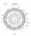
- FIG. 7 is an end-side view of the annular portion 2121 as viewed from the left (i.e. in a first axial direction).
- the annular portion 2121 includes an inner periphery 2121A extending in the axial direction.
- the inner periphery 2121A is a cylindrical surface having a central axis constituted by the central axis 212L.
- the inner periphery 2121A extends straight in the axial direction with a generally constant diameter.
- the inner periphery 2121A is located radially inward of the left end of the cylindrical portion 2122.
- a stop 2121A1 is provided at the right end of the inner periphery 2121A.
- the stop 2121A1 protrudes from the inner periphery 2121A radially inwardly.
- the stop 2121A extends over the entire circumference. That is, the stop 2121A has the shape of a ring.
- the annular portion 2121 includes a plurality of (five in the present embodiment) recesses 2121C.
- the recesses 2121C have the same shape and size.
- the recesses 2121C are located radially outward of the inner periphery 2121A.
- the recesses 2121C overlap the inner periphery 2121A as viewed in a radial direction.
- the recesses 2121C are located along a circle having its center on the central axis 212L.
- the recesses 2121C are separated by an equal distance as measured in the circumferential direction.
- the recesses 2121C are open toward the left (i.e. in the first axial direction).
- Each of the recesses 2121C includes a side 2121C1 and an end surface 2121C2.
- the side 2121C1 extends straight in the axial direction with a generally constant diameter. That is, the side 2121C1 is a cylindrical surface extending in the axial direction.
- the end surface 2121C2 is circular in shape.
- the periphery of the end surface 2121C2 is connected with the right end of the side 2121C1.
- a groove 2121D is provided on the annular portion 2121.
- the groove 2121D has the shape of a ring having a central axial constituted by the central axis 212L.
- the groove 2121D extends in the circumferential direction with a generally constant width (i.e. radial dimension).
- the groove 2121D extends over the entire circumference.
- the groove 2121D is located radially outward of the recesses 2121C.
- the groove 2121D is open toward the left (i.e. in the first axial direction).
- the width (i.e. radial dimension) of the groove 2121 D is larger than the depth (i.e. axial dimension) of the groove 2121D.
- the depth (i.e. axial dimension) of the groove 2121D is smaller than the depth (i.e. axial dimension) of the recesses 2121C.
- a plurality of (four in the present embodiment) grooves 2121 E are provided on the annular portion 2121.
- the grooves 2121E have the same shape and size.
- the grooves 2121E are open toward the left (i.e. in the first axial direction).
- the depth (i.e. axial dimension) of the grooves 2121 E is larger than the depth (i.e. axial dimension) of the recesses 2121C.
- the width of the grooves 2121E are sufficiently smaller than the depth of the grooves 2121 E.
- the grooves 2121E are located radially outward of the groove 2121D.
- the grooves 2121E are located along a circle having its center on the central axis 212L.
- the grooves 2121E are separated by an equal distance as measured in the circumferential direction.
- the grooves 2121E are located at the same positions as the recesses 2121C as determined along the circumferential direction.
- the grooves 2121E extend in the circumferential direction with a generally constant width (i.e. radial dimension).
- the length of each groove 2121E as measured in the circumferential direction is smaller than 1/5 of the circumference of the circle on which the grooves 2121E are located.
- a plurality of (three in the present embodiment) grooves 2121F are provided on the annular portion 2121.
- the grooves 2121F are located radially outward of the grooves 2121E.
- Each of the grooves 2121F has the shape of a ring having a central axis constituted by the central axis 212L.
- the grooves 2121F are arranged in a radial direction.
- the grooves 2121F are separated by an equal distance as measured in a radial direction. That is, the grooves 2121F are positioned to be coaxial.
- Each of the grooves 2121F extends in the circumferential direction with a generally constant width (i.e. radial dimension). Each of the grooves 2121F extends over the entire circumference. The grooves 2121F have the same width.
- the side walls defining a groove 2121F each have the shape of a cylinder having a central axis constituted by the central axis 212L. That is, the side walls defining a groove 2121F (i.e. two side walls adjacent as determined along a radial direction) each extend straight in the axial direction with generally constant inner and outer diameters.
- Each of the sides defining the two ends of the width of a groove 2121F is a cylindrical surface having a central axis constituted by the central axis 212L. That is, the sides defining the two ends of the width of a groove 2121F (i.e. sides facing each other and arranged in a radial direction) each extend straight in the axial direction with a generally constant diameter.
- the grooves 2121F are open toward the left (i.e. in the first axial direction).
- the width (i.e. radial dimension) of the grooves 2121F is smaller than the depth (i.e. axial dimension) of the grooves 2121F.
- the width of the grooves 2121F is not larger than 1/2 of the depth of the grooves 2121F. More preferably, the width of the grooves 2121F is not larger than 1/5 of the depth of the grooves 2121F. Yet more preferably, the width of the grooves 2121F is not larger than 1/10 of the depth of the grooves 2121F.
- the depth (i.e. axial dimension) of the grooves 2121F is larger than the depth (i.e. axial dimension) of the recesses 2121C.
- the depth (i.e. axial dimension) of the one of the grooves 2121F that is located radially outermost, 2121F3, is generally equal to the depth (i.e. axial dimension) of the grooves 2121E.
- the depth (i.e. axial dimension) of the one of the grooves 2121F that is located radially innermost, 2121F1 is larger than the depth (i.e. axial dimension) of the grooves 2121E.
- the depth (axial dimension) of the one of the grooves 2121 F that is located between the grooves 2121F1 and 2121F3 as determined along a radial direction, 2121F2, is larger than the depth (i.e. axial dimension) of the grooves 2121E.
- the depth (i.e. axial dimension) of the groove 2121F1 is generally equal to the depth (i.e. axial dimension) of the groove 2121F2.
- the bottoms of the grooves 2121F are located generally at the same position as the bottoms of the grooves 2121E as determined along the axial direction.
- the open end of the groove 2121F3 is located generally at the same position as the open ends of the grooves 2121E as determined along the axial direction.
- the open end of the groove 2121F1 is located generally at the same position as the open end of the groove 2121F2 as determined along the axial direction.
- the open ends of the grooves 2121F1 and 2121F2 are located toward the left of (i.e. further in the first axial direction than) the open ends of the grooves 2121E.
- the annular portion 2121 includes an outer periphery 2121G.
- the outer periphery 2121G is a cylindrical surface having a central axis constituted by the central axis 212L.
- the outer periphery 2121G extends straight in the axial direction with a generally constant diameter.
- a groove 2121G1 is provided on the outer periphery 2121G.
- the groove 2121G1 has the shape of a ring having a central axis constituted by the central axis 212L.
- the groove 2121G1 extends in the circumferential direction with a generally constant width (i.e. axial dimension).
- the groove 2121G1 extends over the entire circumference.
- the groove 2121G1 is open radially outwardly.
- the outer periphery of the portion of the annular portion located to the right of (i.e. further in a second axial direction than) the groove 2121G1 (i.e. portion forming the right side wall of the groove 2121G) has a larger diameter than the outer periphery 2121G.
- the groove 2121G1 is located adjacent the right end (i.e. furthermost end in the second axial direction) of the outer periphery 2121G.
- the groove 2121G1 is located to the right of (i.e. further in the second axial direction than) the recesses 2121C as viewed in a radial direction.
- the groove 2121G1 overlaps the bottoms of the grooves 2121F as viewed in a radial direction.
- the annular portion 2121 includes lightening recesses 2121H1 and 2121H2, each located between two recesses 2121C adjacent as determined along the circumferential direction.
- the associated ones of the recesses 2121H1 and 2121H2 are arranged in a radial direction. Providing the recesses 2121H1 and 2121H2 reduces the weight of the annular portion 2121C, i.e. wheel hub 212.
- the wheel hub 212 with this construction is rotatably supported by the bearings 25 on the axle 24.
- the bearings 25 will be described with reference to FIG. 4 .
- Each of the bearings 25 is located between the wheel hub 212 and axle 24 as determined along a radial direction.
- the left one of the bearings 25, 251 is located between the left end of the wheel hub 212 (more specifically, inner periphery 2121A of the annular portion 2121) and the axle 24.
- the bearing 251 overlaps the recesses 2121C. As viewed in a radial direction, the bearing 251 overlaps the grooves 2121F.
- the right one of the bearing 25, 252 is located between the right end of the wheel hub 212 (more specifically, inner periphery 2121B of the right end of the cylindrical portion 2122) and the axle 24.
- the bearing 252 is in contact with the stop 2121B1 provided at the left end of the inner periphery 2121B and with the support member 56 supporting the brake caliper 38 such that the stop, bearing and support member are arranged in the axial direction.
- the support member 56 is in contact with the bearing 252 and with the right rear arm 30 such that the bearing, support member and right rear arm are arranged in the axial direction.
- a collar 40 is positioned between the bearings 25 and axle 24.
- the collar 40 as a whole has the shape of a cylinder extending straight in the axial direction.
- the axle 24 is inserted into the collar 40.
- the collar 40 determines the separation (i.e. distance as measured in the axial direction) between the bearings 251 and 252.
- the annular member 23 is attached to the left end (i.e. furthermost end in the first axial direction) of the wheel hub 212.
- the annular member 23 is formed of a metal.
- the metal may be, for example, an aluminum alloy or magnesium alloy.
- the annular member 23 has the shape of a ring having a central axis extending in the left-to-right direction.
- the axle 24 is inserted into the annular member 23.
- the annular member 23 is positioned to be coaxial with the axle 24. That is, the central axis 23L of the annular member 23 matches the central axis 24L of the axle 24.
- the axial, radial and circumferential directions of the annular member 23 are the same as the axial, radial and circumferential directions of the axle 24.
- FIG. 8 is an enlarged cross-sectional view of the annular member 23.
- FIG. 9 is an end-side view of the annular member 23 as viewed from the right (i.e. in the second axial direction).
- the annular member 23 has an inner periphery 23A.
- the inner periphery 23A as a whole, is a cylindrical surface having a central axis constituted by the central axis 23L.
- a support surface 23A1 is provided at the left end of the inner periphery 23A.
- the support surface 23A1 extends straight in the axial direction with a generally constant diameter.
- a stop 23A11 is provided at the right end of the support surface 23A1. The stop 23A11 protrudes from the support surface 23A1 radially inward. The stop 23A11 extends over the entire circumference.
- a plurality of (five in the present embodiment) holes 23C are provided on the annular member 23.
- the holes 23C have the same shape and size.
- the holes 23C extend through the annular member 23 in the axial direction.
- the holes 23C extend straight in the axial direction with a generally constant diameter.
- the inner surface of each hole 23C is a cylindrical surface extending straight in the axial direction.
- the holes 23C are located radially outward of the inner periphery 23A.
- the holes 23C are located along a circle having its center on the central axis 23L.
- the holes 23C are separated by an equal distance as measured in the circumferential direction.
- a plurality of (four in the present embodiment) walls 23D are provided on the annular member 23.
- the walls 23D have the same shape and size.
- the walls 23D are located radially outward of the holes 23C.
- the walls 23D are located along a circle having its center on the central axis 23L.
- the walls 23D are separated by an equal distance as measured in the circumferential direction.
- the walls 23D are located at the same positions as the holes 23C as determined along the circumferential direction.
- the walls 23D extend in the circumferential direction with a generally constant width (i.e. radial dimension).
- the circumferential dimension of each wall 23D is smaller than 1/5 of the circumference of the circle on which the walls 23D are located.
- Each of the walls 23D is located at the same position as one of the holes 23C as determined along the circumferential direction. That is, one wall 23D and one hole 23C are arranged in a radial direction.
- the walls 23D protrude toward the right (i.e. in the second axial direction).
- the width of the walls 23D is sufficiently smaller than the height of the walls 23D.
- a plurality of (three in the present embodiment) walls 23E are provided on the annular member 23.
- the walls 23E are located radially outward of the walls 23D.
- Each of the walls 23E has the shape of a cylinder having a central axis constituted by the central axis 23L of the annular member 23.
- the walls 23E are arranged in a radial direction.
- the walls 23E are separated by an equal distance as measured in a radial direction. That is, the walls 23E are positioned to be coaxial.
- the walls 23E extend in the circumferential direction with a generally constant width (i.e. radial dimension).
- the walls 23E extend over the entire circumference.
- the walls 23E have the same width.
- each of the inner and outer peripheries of a wall 23E is a cylindrical surface having a central axis constituted by the central axis 23L. That is, the inner and outer peripheries of each wall 23E extend straight in the axial direction with generally constant inner and outer diameters, respectively.
- each wall 23E protrude toward the right (i.e. in the second axial direction).
- the width (i.e. radial dimension) of each wall 23E is smaller than the height (i.e. axial dimension) of the walls 23E.
- the width of each wall 23E is not larger than 1/2 of the height of the walls 23E. More preferably, the width of each wall 23E is not larger than 1/5 of the height of the walls 23E. Yet more preferably, the width of each wall 23E is not larger than 1/10 of the height of the walls 23E.
- the height (i.e. axial dimension) of the one of the walls 23E that is located outermost as determined along a radial direction, 23E3, is generally equal to the height (i.e. axial dimension) of the walls 23D.
- the height (axial dimension) of the one of the walls 23E that is located innermost as determined along a radial direction, 23E1 is larger than the height (axial dimension) of the walls 23D.
- the height (axial dimension) of the one of the walls 23E that is located between the walls 23E1 and 23E3 as determined along a radial direction (this wall will be denoted as "23E2") is larger than the height (i.e. axial dimension) of the walls 23D.
- the height of the wall 23E2 is generally equal to the height of the wall 23E1.
- the edges of the walls 23E are located generally at the same position as the edge of the walls 23D as determined along the axial direction.
- the base of the wall 23E3 is located generally at the same position as the base of the walls 23D as determined along the axial direction.
- the base of the wall 23E1 is located generally at the same position as the base of the wall 23E2 as determined along the axial direction.
- the base of the wall 23E1 and the base of the wall 23E2 are located to the left (further in the first axial direction) of the bases of the walls 23D and the base of the wall 23E3.
- the annular member 23 includes a wall 23F.
- the wall 23F is located radially outward of the walls 23E.
- the wall 23F has the shape of a cylinder having a central axis constituted by the central axis 23L of the annular member 23.
- the wall 23F has an inner periphery 23F1.
- the inner periphery 23F1 is a cylindrical surface having a central axis constituted by the central axis 23L.
- the inner periphery 23F1 extends straight in the axial direction with a generally constant diameter.
- the wall 23F includes a recess 23F11.
- the recess 23F11 has the shape of a ring having a central axis constituted by the central axis 23L.
- the recess 23F11 is open at the inner periphery 23F1 and right end surface (i.e. surface of an end as determined along the axial direction) of the wall 23F.
- the recess 23F11 extends in the circumferential direction with a generally constant width (i.e. axial dimension).
- the recess 23F11 extends over the entire circumference.
- the recess 23F11 overlaps the edges of the walls 23E as viewed in a radial direction.
- the annular member 23 includes lightening recesses 23G, each located between two holes 23C adjacent as determined along the circumferential direction. Providing the recesses 23G reduces the weight of the annular member 23.
- the annular member 23 with this construction is rotatably supported on the axle 24 by means of a bearing 28.
- the bearing 28 will be described below with reference to FIG. 5 .
- the bearing 28 is included in the rear wheel 20.
- the bearing 28 is located between the annular member 23 (more specifically, support surface 23A1) and axle 24 as determined along a radial direction.
- the bearing 28 overlaps the sprocket 22 as viewed in a radial direction.
- the bearing 28 is in contact with the stop 23A11 of the support surface 23A1 and with a spacer 58 into which the axle 24 is inserted such that the stop, bearing and spacer are arranged in the axial direction.
- the spacer 58 is in contact with the bearing 28 and with the left rear arm 30 such that the bearing, spacer and left rear arm are arranged in the axial direction.
- a collar 52 is provided between the bearing 28 and axle 24.
- the collar 52 has the shape of a cylinder extending straight in the axial direction.
- the axle 24 is inserted into the collar 52.
- the collar 52 determines the separation (i.e. distance as measured in the axial direction) between the bearing 251 and bearing 28.
- the right end of the collar 52 is present between the bearing 251 and axle 24.
- the left end of the collar 52 is present between the spacer 58 and axle 24.
- the annular member 23 is rotatably supported on the axle 24 by the bearing 28. Further, the annular member 23 is positioned to be coaxial with the wheel hub 212. The annular member 23 is in contact with the wheel hub 212 such that the annular member and wheel hub are arranged in the axial direction. The annular member 23 is rotatable in the circumferential direction relative to the wheel hub 212.
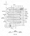
- FIG. 10 is an enlarged cross-sectional view of a portion of FIG. 5 .
- the walls 23D of the annular member 23 protrude toward the wheel hub 212.
- the grooves 2121 E of the wheel hub 212 are open toward the annular member 23.
- Each of the walls 23D is received in the one of the grooves 2121E that is provided at the corresponding position determined along the circumferential direction. That is, one wall 23D is received in one groove 2121E.
- a small gap is provided between the tip surface of a wall 23D and the bottom surface of the corresponding groove 2121E. That is, a small gap is provided between the surface of the wall 23D and the inner surface of the groove 2121E as determined along the axial direction.
- a small gap is provided between a side of the wall 23D and the associated side of the groove 2121E. That is, a small gap is provided between the surface of the wall 23D and the inner surface of the groove 2121E as determined along a radial direction.
- the circumferential dimension of the wall 23D is smaller than the circumferential dimension of the groove 2121E. This permits circumferential movement of the wall 23D inside the groove 2121E.
- the walls 23E of the annular member 23 protrude toward the wheel hub 212.
- the grooves 2121F of the wheel hub 212 are open toward the annular member 23.
- Each of the walls 23E is received in the one of the grooves 2121 F that is provided at the corresponding position determined along a radial direction.
- a small gap is provided between the tip surface of a wall 23E and the bottom surface of the corresponding groove 2121F. That is, a small gap is provided between the surface of the wall 23E and the inner surface of the groove 2121F as determined along the axial direction. A small gap is provided between a side of the wall 23E and the associated side of the groove 2121F. That is, a small gap is provided between the surface of the wall 23E and the inner surface of the groove 2121F as determined along a radial direction.
- Each of the walls 23E and each of the grooves 2121F extend over the entire circumference. This permits circumferential movement of the walls 23E within the grooves 2121F.
- the gap between a side of a wall 23E and the associated side of the corresponding groove 2121F is smaller than the gap between the tip surface of the wall 23E and the bottom surface of the groove 2121F.
- the gap between the side of the wall 23E and the side of the groove 2121F is smaller than the thickness (i.e. radial dimension) of the wall 23E.
- the gap between the side of the wall 23E and the side of the groove 2121F is smaller than 1/2 of the thickness of the wall 23E. More preferably, the gap between the side of the wall 23E and the side of the groove 2121F is larger than 1/20 of the thickness of the wall 23E.
- the gaps between the surfaces of the walls 23E and the inner surfaces of the grooves 2121F are filled with a viscous fluid 42.
- the viscous fluid 42 may be a silicone grease, for example.
- the viscosity of the viscous fluid 42 is only required to be large enough to provide a damping effect derived from shear resistance, as discussed further below.
- the viscosity of the viscous fluid 42 may be 10000 centistokes (cSt) or larger, for example.
- the seal ring 44 will be described with reference to FIG. 10 .
- the seal ring 44 is formed of a rubber material.
- the rubber material may be a nitrile rubber (NBR), for example.
- the seal ring 44 has the shape of a ring having a central axis constituted by the central axis 212L.
- the seal ring 44 is positioned in the groove 2121D formed in the wheel hub 212. That is, the seal ring 44 is positioned to be coaxial with the wheel hub 212.
- the seal ring 44 is located between the annular member 23 and wheel hub 212 as determined along the axial direction. In this state, the seal ring 44 is compressed in the axial direction. As such, the seal ring 44 prevents the viscous fluid 42 from leaking from the groove 2121D radially inwardly. That is, the seal ring 44 seals in the viscous fluid 42 between the annular member 23 and wheel hub 212.
- the wall 23F of the annular member 23 is located radially outward of the annular portion 2121 of the wheel hub 212.
- the edge of the wall 23F is located generally at the same position as the rightmost position of the annular portion 2121 as determined along the axial direction.
- the wall 23F overlaps the annular portion 2121. That is, the wall 23F covers the outer periphery 2121G of the annular portion 2121.
- the inner periphery 23F1 of the wall 23F is located radially outward of the outer periphery 2121G.
- a gap is provided between the inner periphery 23F1 of the wall 23F and the outer periphery 2121G of the annular portion 2121. In this state, the recess 23F11 in the inner periphery 23F1 overlaps the groove 2121G in the outer periphery 2121G as viewed in a radial direction.
- the seal ring 46 will be described with reference to FIG. 10 .
- the seal ring 46 is formed of a rubber material.
- the rubber material may be a nitrile rubber (NBR), for example.
- the seal ring 46 has the shape of a ring having a central axis constituted by the central axis 212L
- the seal ring 46 is located between the groove 2121G1 and recess 23F11. That is, the seal ring 46 is provided between the annular member 23 and wheel hub 212 as determined along a radial direction. In other words, the seal ring 46 is positioned to be coaxial with the wheel hub 212. In this state, the seal ring 46 is compressed in radial directions. As such, the seal ring 46 prevents the viscous fluid 42 from leaking to the right (i.e. in the second axial direction) from the groove 2121G1 and recess 23F11. That is, the seal ring 46 seals in the viscous fluid 42 between the annular member 23 and wheel hub 212.
- the bush 48 will be described with reference to FIG. 10 .
- the bush 48 is a thin oilless slide bearing.
- the bush 48 may be formed of, for example, a fluorine-based resin or a nylon-based resin.
- the bush 48 may be formed of a combination of such a resin with a metal (for example, copper).
- the bush 48 is provided between the inner periphery 23F1 of the wall 23F of the annular member 23 and the outer periphery 2121G of the annular portion 2121.
- the bush 48 as a whole, has the shape of a cylinder having a central axis constituted by the central axis 23L.
- the bush 48 is located toward the left of the seal ring 46.
- a stop 481 is provided on the left end (i.e. end as determined along the axial direction) of the bush 48.
- the stop 481 extends from the left end of the bush 48 radially inwardly.
- the stop 481 extends over the entire circumference.
- the stop 481 is in contact with the edge of the radially outward one of the walls defining the groove 2121F3 of the annular portion 2121 and with the annular member 23 such that the edge, stop and annular member are arranged in the axial direction. This determines the axial position of the bush 48. This prevents the bush 48 from moving in an axial direction and contacting the seal ring 46.
- the coupling members 26 will be described with reference to FIG. 5 .
- the coupling members 26 have the same shape and size.
- Each of the coupling members 26 includes a body 261 and an elastic member 262, These components will be described below.
- the body 261 is formed of a metal.
- the metal may be, for example, a chromium-molybdenum steel (SCM 435, for example).
- SCM 435 chromium-molybdenum steel
- the body 261 includes a base 2611 and a stem 2612.
- the base 2611 has the shape of a thick disc or a cylinder.
- the base 2611 has a cylindrical outer periphery extending straight in the axial direction with a generally constant diameter.
- the stem 2612 has the shape of a cylinder with a smaller diameter than the base 2611. That is, the stem 2612 extends straight in the axial direction with a generally constant diameter. A thread is formed on the side of the tip of the stem 2612.
- the stem 2612 protrudes from the left end of the base 2611 in the axial direction.
- the stem 2612 is formed to be coaxial with the base 2611.
- the elastic member 262 is formed of a rubber material.
- the rubber material may be a nitrile rubber (NBR), for example.
- NBR nitrile rubber
- the elastic member 262 may be formed of a resin elastomer, for example.
- the resin elastomer may be polyurethane, for example.
- the elastic member 262 has the shape of a ring having a central axis constituted by the central axis of the body 261. That is, the elastic member 262 extends straight in the axial direction with generally constant inner and outer diameters.
- the axial dimension of the elastic member 262 is generally equal to the axial dimension of the base 2611.
- the inner periphery of the elastic member 262, over its entire axial dimension, is bonded to the outer periphery of the base 2611. In this state, the elastic member 262 covers the entire outer periphery of the base 2611.
- each coupling member 26 is received in the associated one of the recesses 2121C of the annular portion 2121. That is, the walls 23E of the annular member 23 and the grooves 2121F of the annular portion 2121 are located radially outward of the elastic members 262. As viewed in a radial direction, the elastic members 262 overlap the walls 23E and grooves 2121F. As viewed in a radial direction, the elastic members 262 overlap the bearing 251.
- the side of the elastic member 262 is in contact with the side 2121C1 of the recess 2121C.
- the elastic member 262 may be compressed between the side 2121C1 of the recess 2121C and the outer periphery of the base 2611.
- the elasticity of the elastic member 262 may be used to bring the outer periphery of the elastic member 262 into close contact with the side 2121C1 of the recess 2121C.
- the openings of the recesses 2121C in the annular portion 2121 are covered with the annular member 23.
- the stems 2612 are inserted into the holes 23C in the annular member 23.
- the tips of the stems 2612 are located to the left of the holes 23C. That is, the tips of the stems 2612 are located outside the holes 23C. In this state, a portion of each stem 2612 that is located outside the associated hole 23C is inserted into a hole 221 formed in the sprocket 22.
- the tip of the stem 2612 is located to the left of the sprocket 22. That is, the stem 2612 extends through the sprocket 22.
- a nut 50 is fixed to a portion of the stem 2612 that is located to the left of the sprocket 22.
- the sprocket 22 is coupled to the annular member 23.
- the chain 32 is wound around the sprocket 22. Driving power from the engine 14 is transmitted to the sprocket 22 via the chain 32.
- FIG. 11 is a graph showing the driving power transmitted to the rear wheel 20. As shown in FIG. 11 , the driving power transmitted to the rear wheel 20 constantly varies.
- Factors behind the variations in the driving power include: throttle-lever operations by the rider, variations in the torque itself generated by the engine 14 (for example, variations caused by the unevenness of the combustion state), those produced in the route of transmission of driving power from the engine 14 to the rear wheel 20 (for example, those caused by the engagement of the gears of the transmission, or those caused by the vibration of the chain 22, for example), those caused by shocks generated by shift changes during acceleration and deceleration, and those caused by the engine brake during deceleration.
- the driving power transmitted to the rear wheel 20 may vary due to road surface conditions.
- the conditions of the road surface itself for example, unevenness of the pavement, cracks on the road surface, and bumps on the road surface
- changes in the friction between the road surface and rear wheel 20 may cause the driving power transmitted to the rear wheel 20 to vary.
- the motorcycle 10 is capable of damping the vibration caused by the variations in the driving power transmitted to the rear wheel 20. This feature will be described below.
- the driving power from the engine 14 is transmitted to the sprocket 22 via the chain 32.
- the sprocket 22 is coupled to the annular member 23 by means of the coupling members 26 and the nuts 50 attached to the coupling members 26.
- the driving power from the engine 14 transmitted to the sprocket 22 via the chain 32 causes the sprocket 22 to begin to rotate, the annular member 23 rotates relative to the wheel hub 212 in the circumferential direction.
- the elastic members 262 provided on the coupling members 26 are compressed. This will reduce impacts produced when the annular member 23 is rotating relative to the wheel hub 212 in the circumferential direction.
- the annular member 23 is held by the coupling members 26 (more specifically, elastic members 262 and bases 2611) at the position of the annular member after its rotation relative to the wheel hub 212. In this state, the rotation of the annular member 23 is transmitted to the wheel hub 212 via the coupling members 26. This causes the annular member 23 to rotate together with the wheel hub 212. As a result, the motorcycle 10 travels.
- the driving power transmitted to the rear wheel 20 via the chain 32 may vary. Further, for some road surface conditions, movements may be directly transferred to the rear wheel 20. These variations/movements cause vibrations in the rear wheel 20. More specifically, vibrations are produced in the rear wheel that cause one of the annular member 23 and wheel hub 212 to rotate relative to the other with respect to their positions after the rotation of the annular member 23 relative to the wheel hub 212.
- the walls 23E, grooves 2121F and viscous fluid 42 implement a damping mechanism 27.
- the damping mechanism 27 uses the viscous fluid 42 filling the gap between the annular member 23 and annular portion 2121 to damp vibrations.
- the damping mechanism 27 overlaps the bearing 251 as viewed in a radial direction.
- each of the walls 23E of the annular member 23 extends over the entire circumference.
- Each of the grooves 2121F of the wheel hub 212 extends over the entire circumference.
- the walls 23E and grooves 2121F have relatively large circumferential dimensions.
- the sides of the walls 23E and the portions of the inner surfaces of the grooves 2121F that face the sides of the walls 23E as determined along a radial direction have relatively large areas. This will increase the damping forces derived from the shear resistance of the viscous fluid 42.
- the walls 23E of the annular member 23 are arranged in a radial direction.
- the grooves 2121F of the wheel hub 212 are also arranged in a radial direction.
- the numbers of the walls 23E and grooves 2121F are increased.
- the sides of the walls 23E and the portions of the inner surfaces of the grooves 2121F that face the sides of the walls 23E as determined along a radial direction as a whole have increased areas. This will increase the damping forces derived from the shear resistance of the viscous fluid 42.
- the walls 23E of the annular member 23 are located radially outward of the elastic members 262.
- the grooves 2121F of the wheel hub 212 are also located radially outward of the elastic members 262.
- the walls 23E and grooves 2121F have relatively large circumferential dimensions.
- the sides of the walls 23E and the portions of the inner surfaces of the grooves 2121F that face the sides of the walls 23E as determined along a radial direction have increased areas. This will increase the damping forces derived from the shear resistance of the viscous fluid 42.
- the elastic members 262 and damping mechanism 27 overlap the bearing 251 as viewed in the radial direction.
- the elastic members 262 and damping mechanism 27 are unlikely to be affected by loads input into the rear wheel 20 in a radial direction.
- a bush 48 is provided between the inner periphery 23F of the annular member 23 and the outer periphery 2121G of the annular portion 2121.
- the bush 48 maintains the separation (i.e. radial distance) between the outer periphery 2121G and inner periphery 23F at an appropriate level. This will maintain the annular member 23 at an appropriate radial position relative to the wheel hub 212.
- the shear resistance of the viscous fluid 42 is used to damp vibrations that circumferentially rotate one of the annular member 23 and wheel hub 212 relative to the other; alternatively, for example, vibrations may be damped using the circumferential flow of the viscous fluid produced when one of the annular member 23 and wheel hub 212 rotates relative to the other.
- vibrations may be damped using the circumferential flow of the viscous fluid produced when one of the annular member 23 and wheel hub 212 rotates relative to the other.
- FIG. 12 is only intended to illustrate an example application of the damping mechanism, and does not show the relationship between the damping mechanism and elastic members.
- the damping mechanism 27A shown in FIG. 12 includes an annular member 231 having a pair of partition walls 2311.
- the partition walls 2311 partition a fluid chamber 54 defined by the annular member 231 and wheel hub 212A into sub-chambers arranged in the circumferential direction.
- One of the sub-chambers, formed on one side of the partition wall 2311 as determined along the circumferential direction, will be referred to as fluid chamber 541.
- the other sub-chamber, formed on the other side of the partition wall 2311 as determined along the circumferential direction will be referred to as fluid chamber 542.
- An orifice 23111 is formed in each of the partition walls 2311. Each orifice 23111 extends in the circumferential direction. The orifices 23111 allow the two fluid chambers 541 and 542 to communicate.
- the spring characteristics of the elastic member 262 exhibited when the motorcycle 10 accelerates may be different from the spring characteristics in the direction in which the motorcycle decelerates.
- a slit 262A may be formed within a portion of the elastic member 262 that contacts the wheel hub 212 when the motorcycle 10 decelerates.
- an elastic member 262B may be composed of an elastic member 262B1 that contacts the wheel hub 212 when the motorcycle 10 is accelerates and an elastic member 262B2 that contacts the wheel hub 212 when the motorcycle 10 decelerates.
- a plurality of (three in the implementation shown in FIG. 14 ) holes 262B21 are formed in the elastic member 262B2 to further facilitate deformation of the elastic member 262B2.
- a portion of an elastic member that contacts the wheel hub 212 when the motorcycle 10 accelerates may be made of a certain material while a portion that contacts the wheel hub 212 when the motorcycle 10 decelerates may be made of a different material.
- the spring characteristics exhibited when the motorcycle 10 decelerates are softer than the spring characteristics in the direction in which the motorcycle 10 accelerates.
- the driving power from the engine 14 transmitted to the elastic members when the annular member 23 rotates relative to the wheel hub 212 during acceleration of the motorcycle 10 is larger than that during deceleration of the motorcycle 10.
- the spring characteristics discussed above will facilitate relative rotation of the annular member 23 relative to the wheel hub 212 even during deceleration of the motorcycle 10. This will facilitate damping of vibrations even during deceleration of the motorcycle 10.
- impacts produced when the annular member 23 rotates relative to the wheel hub 212 can be reduced.
- the elastic member may be springs 262C.
- the springs 262C are provided on both sides of the base 26A11 of the body 26A1 of the coupling member 26A as determined along the circumferential direction.
- the springs 262C and body 26A1 are positioned within a recess 212B1 formed in the wheel hub 212B.
- one spring 262C is pulled while the other spring 262C is compressed. This will reduce impacts produced when the annular member 23 rotates relative to the wheel hub 212.
Landscapes
- Engineering & Computer Science (AREA)
- Mechanical Engineering (AREA)
- General Engineering & Computer Science (AREA)
- Chemical & Material Sciences (AREA)
- Combustion & Propulsion (AREA)
- Transportation (AREA)
- Physics & Mathematics (AREA)
- Acoustics & Sound (AREA)
- Aviation & Aerospace Engineering (AREA)
- Axle Suspensions And Sidecars For Cycles (AREA)
- Automatic Cycles, And Cycles In General (AREA)
Abstract
Description
- The present invention relates to a straddled vehicle, and more particularly, to a straddled vehicle where driving power from the engine is transmitted to the rear wheel via a chain.
- Known straddled vehicles include motorcycles. In a motorcycle, driving power from the engine is transmitted to the rear wheel via a chain. This causes the motorcycle to travel.
- A motorcycle travels while being affected by various factors. Particularly, a race motorcycle travels at high speeds by exploiting its performance to the maximum extent and, as such, the travelling of such a motorcycle is affected by those various factors to larger degrees.
- The various factors affecting the travelling of the motorcycle are categorized as external factors and internal factors. The external factors include, for example, road surface conditions, changes in the friction between the road surface and tire, changes in the grounding load of the rear wheel, and winds hitting the travelling vehicle. The internal factors include, for example, variations in the driving power transmitted to the rear wheel. Variations in the driving power transmitted to the rear wheel include, for example, those originating from throttle-lever operations by the rider, those resulting from variations in the torque generated by the engine, those produced in the route of transmission of driving power from the engine to the rear wheel, and those caused by shocks generated by shift changes during acceleration and deceleration. As they are transmitted to the wheel body via the chain and sprocket, vibrations occur in the rear wheel. Further, external factors may cause movements of the wheel body via the tire, causing vibrations in the rear wheel, In addition, these variations/movements may affect each other, deteriorating the vibrations in the rear wheel.
-
JP 2007-118684 A - According to the above publication, the dampers are made of rubber. This arrangement may reduce impact-like loads transmitted to the rear wheel via the chain. However, it is not sufficient for damping vibrations caused by variations in the driving power transmitted to the rear wheel via the chain. Further, it is not sufficient for damping vibrations caused by movements transmitted to the rear wheel from the road surface.
- An object of the present invention is to provide a straddled vehicle capable of damping vibrations in the rear wheel caused by variations in the driving power transmitted to the rear wheel via the chain or movements transmitted to the rear wheel from the road surface.
- According to the present invention said object is solved by a straddled vehicle having the features of independent claim 1. Preferred embodiments are laid down in the dependent claims.
- A straddled vehicle according to an embodiment includes: an engine; a rear wheel; and a chain. The rear wheel is located rearward of the engine. The chain transmits driving power from the engine to the rear wheel. The rear wheel includes an axle, a wheel hub, a plurality of bearings, an annular member, a sprocket, an elastic member, and a damping mechanism. The axle extends in the left-to-right direction with respect to the vehicle. The wheel hub is shaped as a cylinder that extends in the left-to-right direction with respect to the vehicle. The axle is inserted through the wheel hub. The plurality of bearings are located between the wheel hub and the axle as determined along a radial direction of the wheel hub. The plurality of bearings rotatably support the wheel hub on the axle. The annular member is attached to an end of the wheel hub as determined along the axial direction thereof. The annular member is positioned to be coaxial with the wheel hub. The annular member is positioned to be rotatable relative to the wheel hub in a circumferential direction of the wheel hub. The sprocket is coupled to the annular member. The chain is wound around the sprocket. When the annular member rotates relative to the wheel hub, the elastic member elastically deforms depending on the amount of rotation of the annular member relative to the wheel hub. The annular member rotates relative to the wheel hub when driving power is transmitted to the annular member via the sprocket. The damping mechanism damps a vibration in one of the annular member and the wheel hub after the annular member has rotated relative to the wheel hub. The vibration to be damped by the damping mechanism is a vibration acting to rotate one of the annular member and the wheel hub relative to the other in a circumferential direction with respect to their positions after the rotation of the annular member relative to the wheel hub.
- The above-described straddled vehicle may damp vibrations in the rear wheel caused by variations in the driving power transmitted to the rear wheel via the chain or movements transmitted to the rear wheel from the road surface.
-
- [
FIG. 1] FIG. 1 is a left side view of a motorcycle according to an embodiment. - [
FIG. 2] FIG. 2 is a perspective view of the rear wheel of the motorcycle shown inFIG. 1 . - [
FIG. 3] FIG. 3 is an exploded perspective view of the rear wheel of the motorcycle shown inFIG. 1 . - [
FIG. 4] FIG. 4 is a cross-sectional view of the rear wheel of the motorcycle shown inFIG. 1 . - [
FIG. 5] FIG. 5 is an enlarged cross-sectional view of a portion ofFIG. 4 . - [
FIG. 6] FIG. 6 is an enlarged cross-sectional view of the annular portion of wheel hub. - [
FIG. 7] FIG. 7 is an end-side view of the annular portion of the wheel hub as seen in an axial direction. - [
FIG. 8] FIG. 8 is an enlarged cross-sectional view of the annular member. - [
FIG. 9] FIG. 9 is an end-side view of the annular member as viewed in an axial direction. - [
FIG. 10] FIG. 10 is an enlarged cross-sectional view of a portion ofFIG. 5 . - [
FIG. 11] FIG. 11 is a graph showing the magnitude of the driving power transmitted to the rear wheel when the motorcycle is travelling. - [
FIG. 12] FIG. 12 is a conceptual view of an example application of the damping mechanism. - [
FIG. 13] FIG. 13 illustrates an example application of an elastic member, - [
FIG. 14] FIG. 14 illustrates another example application of the elastic member. - [
FIG. 15] FIG. 15 illustrates yet another example application of the elastic member, - A straddled vehicle according to an embodiment includes: an engine; a rear wheel; and a chain. The rear wheel is located rearward of the engine. The chain transmits driving power from the engine to the rear wheel. The rear wheel includes an axle, a wheel hub, a plurality of bearings, an annular member, a sprocket, an elastic member, and a damping mechanism. The axle extends in the left-to-right direction with respect to the vehicle. The wheel hub is shaped as a cylinder that extends in the left-to-right direction with respect to the vehicle. The axle is inserted through the wheel hub. The plurality of bearings are located between the wheel hub and the axle as determined along a radial direction of the wheel hub. The plurality of bearings rotatably support the wheel hub on the axle. The annular member is attached to an end of the wheel hub as determined along the axial direction thereof. The annular member is positioned to be coaxial with the wheel hub. The annular member is positioned to be rotatable relative to the wheel hub in a circumferential direction of the wheel hub. The sprocket is coupled to the annular member. The chain is wound around the sprocket. When the annular member rotates relative to the wheel hub, the elastic member elastically deforms depending on the amount of rotation of the annular member relative to the wheel hub. The annular member rotates relative to the wheel hub when driving power is transmitted to the annular member via the sprocket. The damping mechanism damps a vibration in one of the annular member and the wheel hub after the annular member has rotated relative to the wheel hub. The vibration to be damped by the damping mechanism is a vibration acting to rotate one of the annular member and the wheel hub relative to the other in a circumferential direction with respect to their positions after the rotation of the annular member relative to the wheel hub.
- In the above-described straddled vehicle, the driving power transmitted from the engine via the chain rotates the sprocket. The sprocket is coupled to the annular member. Thus, as the sprocket rotates, the annular member rotates. The annular member is positioned to be rotatable relative to the wheel hub. Thus, when the sprocket begins to rotate, the annular member rotates relative to the wheel hub. At this moment, the elastic member elastically deforms. This will reduce impacts produced when the annular member rotates relative to the wheel hub.
- The relative rotation of the annular member relative to the wheel hub is restricted by the elastic member. Thus, the annular member is held by the elastic member at the position of the annular member after its rotation relative to the wheel hub. That is, the force that causes the elastic member to elastically deform and the biasing force generated by this elastic deformation are in balance. In this state, the rotation of the annular member is transmitted to the wheel hub via the elastic member. Thus, the annular member and wheel hub rotate while keeping their balanced position. As a result, the straddled vehicle travels.
- When the straddled vehicle is travelling, the driving power transmitted to the rear wheel via the chain may vary. Further, for some road conditions, movements are directly transmitted to the rear wheel. These variations/movements cause vibrations in the rear wheel. More specifically, vibrations are produced in the rear wheel that cause one of the annular member and wheel hub to rotate relative to the other with respect to their positions after the rotation of the annular member relative to the wheel hub.
- In the above-described straddled vehicle, the rear wheel includes a damping mechanism. This will damp vibrations in the rear wheel (more specifically, vibrations that cause one of the annular member and wheel hub to rotate relative to the other with respect to their positions after the rotation of the annular member relative to the wheel hub).
- Preferably, the damping mechanism damps the vibration using a viscous fluid enclosed between the annular member and the wheel hub. In such implementations, the damping of the vibration by the damping mechanism may be achieved using the shear resistance of the viscous fluid produced when one of the annular member and the wheel hub rotates relative to the other, or using the flow resistance of the viscous fluid produced when one of the annular member and wheel hub rotates relative to the other.
- Preferably, a wall is provided on one of the wheel hub and the annular member and a groove is provided on the other one of the wheel hub and annular member. The wall protrudes in the axial direction toward the other one of the wheel hub and the annular member, and extends in a circumferential direction. The groove is open toward the one of the wheel hub and the annular member to face in the axial direction, and extends in the circumferential direction. The wall is received by the groove and is permitted to move in a circumferential direction. A gap is provided between the inner surface of the groove and a side of the wall as determined along a radial direction of the wheel hub. The gap is filled with the viscous fluid. The size of the gap is smaller than the thickness of the wall as measured in a radial direction.
- This arrangement achieves a damping mechanism using the shear resistance of the viscous fluid. The number, height and circumferential dimension of the walls is decided depending on the desired damping characteristics. The same applies to the number, depth and circumferential dimension of the grooves.
- Preferably, the wall and the groove extend over the entire circumference. In such implementations, the circumferential dimensions of the wall and groove are relatively large. This increases the area of the side of the wall and the area of the portion of the inner surface of the groove that faces the side of the wall as determined along the radial direction of the wheel hub. This will provide large damping forces.
- In other implementations, the wall may not extend over the entire circumference but the groove may extend over the entire circumference. In such implementations, too, the circumferential dimension of the wall and the height of the wall (i.e. axial dimension) may be decided appropriately to provide the desired damping characteristics.
- Preferably, a plurality of walls and a plurality of grooves are arranged in a radial direction. In such implementations, the number of the walls and grooves are increased. This increases the total area of the sides of the walls and the total area of the side portions of the inner surfaces of the grooves that face the sides of the walls as determined along the radial direction of the wheel hub. This will provide large damping forces.
- Preferably, the wall and the groove are located radially outward of the elastic member. In such implementations, the circumferential dimensions of the wall and groove are increased. This increases the area of the side of the wall and the area of the side portion of the inner surface of the groove that faces the side of the wall as determined along a radial direction of the wheel hub. This will provide large damping forces.
- Preferably, the rear wheel further includes a seal ring. The seal ring is located between the annular member and the wheel hub. The seal ring may be located between the annular member and wheel hub as determined along the axial direction, or may be located between the annular member and wheel hub as determined along a radial direction. The seal ring is positioned to be coaxial with the wheel hub. The seal ring seals in the viscous fluid between the annular member and wheel hub.
- In such implementations, the viscous fluid can be held between the annular member and wheel hub. This will stabilize the damping of vibrations by the damping mechanism.
- When one of the annular member and wheel hub rotates relative to the other, friction is generated between the seal ring and annular member and between the seal ring and wheel hub. Such friction acts as a resistance that prevents the rotation of one of the annular member and wheel hub relative to the other. This will reduce the rotation of one of the annular member and wheel hub relative to the other.
- Preferably, at least one of the elastic member and damping mechanism overlaps one of the plurality of bearings as viewed in a direction perpendicular to the axial direction. In such implementations, the one of the elastic member and damping mechanism that overlaps one of the bearings as viewed in a direction perpendicular to the axial direction is less likely to be affected by a load input into the rear wheel (more specifically, wheel hub) in a direction perpendicular to the axial direction.
- Preferably, one of the wheel hub and the annular member includes a cylindrical outer periphery extending in the axial direction and the other one of the wheel hub and the annular member includes a cylindrical inner periphery extending in the axial direction. The inner periphery is located radially outward of the outer periphery. The inner periphery overlaps the outer periphery as viewed in a radial direction. The rear wheel further includes a bush. The bush is located between the outer periphery and the inner periphery and shaped as a cylinder extending in the axial direction.
- In such implementations, the bush maintains the distance between the outer and inner peripheries (i.e. distance in a radial direction) at an appropriate level. As a result, the annular member can be maintained at an appropriate radial position relative to the wheel hub.
- Preferably, the spring characteristics of the elastic member in the direction of rotation of the annular member relative to the wheel hub during deceleration of the straddled vehicle are softer than the spring characteristics thereof in the direction of rotation of the annular member relative to the wheel hub during acceleration of the straddled vehicle.
- The driving power of the engine transmitted to the elastic member as the annular member rotates relative to the wheel hub may be driving power during acceleration of the straddled vehicle (i.e. positive driving power) and driving power during deceleration of the straddled vehicle (i.e. negative driving power). The absolute value of the driving power during acceleration of the straddled vehicle is larger than the absolute value of the driving power during deceleration of the straddled vehicle. Thus, the spring characteristics described above will facilitate relative rotation of the annular member relative to the wheel hub even when the straddled vehicle is decelerating. As a result, the vibration damping effect can be easily obtained even when the straddled vehicle is decelerating. Further, when the straddled vehicle is accelerating, the impact absorption effect desired when the annular member rotates relative to the wheel hub can be provided.
- The elastic member may be formed from a material capable of elastically deforming when one of the annular member and wheel hub rotates relative to the other. The elastic member may be formed from, for example, rubber or resin elastomer.
- The straddled vehicle according to an embodiment will be described below with reference to the drawings. In the present embodiment, a motorcycle will be described as an example of the straddled vehicle. The same or corresponding portions in the drawings are labeled with the same reference characters and their description will not be repeated.
- In the following description, the forward and rearward directions, the left and right directions and the up and down directions are those as viewed from the rider sitting on the seat of the motorcycle. The axial, radial and circumferential directions are those with respect to the central axis of the axle of the rear wheel. That is, axial direction means the direction in which the central axis of the axle of the rear wheel extends. Radial direction means a direction perpendicular to the central axis of the axle of the rear wheel, i.e. a direction perpendicular to the axial direction. Circumferential direction means a direction about the central axis of the axle of the rear wheel. In the drawings referred to in the following description, arrow F indicates the forward direction with respect to the vehicle, arrow U indicates the upward direction with respect to the vehicle, and arrow L indicates the left direction with respect to the vehicle.
-
FIG. 1 is a schematic left side view of amotorcycle 10. Referring toFIG. 1 , themotorcycle 10 includes anengine 14, arear wheel 20, and achain 32. - The
engine 14 is supported on the vehicle-body frame 12. Afront fork 16 is attached to a front portion of the vehicle-body frame 12. Thefront fork 16 rotatably supports thefront wheel 18. - A pair of
rear arms 30, to the left and right, are attached to the vehicle-body frame 12. The left and rightrear arms 30 rotatably support therear wheel 20. - The
rear wheel 20 is located rearward of theengine 14. Driving power of theengine 14 is transmitted to therear wheel 20 via thechain 32. This causes therear wheel 20 to rotate. - The
rear wheel 20 of themotorcycle 10 will be described with reference toFIGS. 2 ,3 ,4 and5 .FIG. 2 is a perspective view of therear wheel 20.FIG. 3 is an exploded perspective view of therear wheel 20.FIG. 4 is a cross-sectional view of therear wheel 20.FIG. 5 is an enlarged cross-sectional view of a portion ofFIG. 4 .FIGS. 2 and3 do not show the tire 200 (seeFIG. 1 ) and axle (seeFIG. 4 ) mounted on thewheel body 21.FIGS. 4 and5 do not show the tire 200 (seeFIG. 1 ),rim 211 andspokes 213. - The
rear wheel 20 includes awheel body 21, asprocket 22, anannular member 23, anaxle 24, a plurality of (two in the present embodiment)bearings 25, a plurality of (five in the present embodiment)coupling members 26, seal rings 44 and 46, and abush 48. These components will be described below. - The
wheel body 21 will be described with reference toFIGS. 2 and3 . Thewheel body 21 includes arim 211, awheel hub 212, and a plurality ofspokes 213. - The tire 200 (see
FIG. 1 ) is attached to therim 211. Therim 211 has the shape of a cylinder having a central axis constituted by an axis extending in the left-to-right direction (more specifically,central axis 24L of the axle 24). - The
wheel hub 212 is located radially inward of therim 211. Thewheel hub 212 is positioned to be coaxial with therim 211. Thewheel hub 212 is integral with therim 211. Thewheel hub 212 will be described in more detail further below. - The
spokes 213 are located between thewheel hub 212 andrim 211. Thespokes 213 connect thewheel hub 212 with therim 211. - The
axle 24 will be described with reference toFIG. 4 . Theaxle 24 extends in the left-to-right direction to connect the left and rightrear arms 30. That is, thecentral axis 24L of theaxle 24 extends in the left-to-right direction. Theaxle 24 is formed of a metal. The metal may be, for example, a chromium-molybdenum steel (SCM 435, for example). Theaxle 24 is inserted into thewheel hub 212. - The
wheel hub 212 will be described with reference toFIG. 4 . Thewheel hub 212 as a whole has the shape of a cylinder having a central axis extending in the left-to-right direction. Thewheel hub 212 is positioned to be coaxial with theaxle 24. That is, thecentral axis 212L of thewheel hub 212 matches thecentral axis 24L of theaxle 24. Thus, the axial, radial and circumferential directions of thewheel hub 212 are the same as the axial, radial and circumferential directions of theaxle 24. Thewheel hub 212 is located between therear arms 30. That is, theaxle 24 extends through thewheel hub 212. - The
wheel hub 212 is formed of a metal. The metal may be, for example, an aluminum alloy or magnesium alloy. Thewheel hub 212 includes acylindrical portion 2122 and anannular portion 2121. - The
cylindrical portion 2122 as a whole has the shape of a cylinder having a central axis constituted by thecentral axis 212L. The outer and inner diameters of the left end of thecylindrical portion 2122 are larger than the inner and outer diameters of the right end of thecylindrical portion 2122. - An inner periphery 2121B is provided on the right end of the
cylindrical portion 2122. The inner periphery 2121B is a cylindrical surface having a central axis constituted by thecentral axis 212L. The inner periphery 2121B extends straight in the axial direction with a generally constant diameter. - A stop 2121B1 is provided at the left end of the inner periphery 2121B. The stop 2121B1 protrudes from the inner periphery 2121B radially inwardly. The stop 2121B1 extends over the entire circumference.
- A
disk rotor 34 is fixed to the right end of thecylindrical portion 2122 by a plurality ofbolts 36. An operation by the rider causes abrake pad 381 provided on abrake caliper 38 to be pressed onto thedisk rotor 34. This reduces the rotational speed of therear wheel 20. - The
brake caliper 38 is attached to asupport member 56 into which theaxle 24 is inserted. Thesupport member 56 is located between the rightrear arm 30 andcylindrical portion 2122 as determined along the axial direction. - As shown in
FIG. 5 , theannular portion 2121 is connected to the left end of thecylindrical portion 2122. Theannular portion 2121 as a whole has the shape of a ring having a central axis constituted by thecentral axis 212L. - The
annular portion 2121 will be described with reference toFIGS. 6 and7 .FIG. 6 is an enlarged cross-sectional view of theannular portion 2121.FIG. 7 is an end-side view of theannular portion 2121 as viewed from the left (i.e. in a first axial direction). - As shown in
FIG. 6 , theannular portion 2121 includes aninner periphery 2121A extending in the axial direction. Theinner periphery 2121A is a cylindrical surface having a central axis constituted by thecentral axis 212L. Theinner periphery 2121A extends straight in the axial direction with a generally constant diameter. Theinner periphery 2121A is located radially inward of the left end of thecylindrical portion 2122. - A stop 2121A1 is provided at the right end of the
inner periphery 2121A. The stop 2121A1 protrudes from theinner periphery 2121A radially inwardly. Thestop 2121A extends over the entire circumference. That is, thestop 2121A has the shape of a ring. - As shown in
FIG. 7 , theannular portion 2121 includes a plurality of (five in the present embodiment) recesses 2121C. Therecesses 2121C have the same shape and size. - The
recesses 2121C are located radially outward of theinner periphery 2121A. Therecesses 2121C overlap theinner periphery 2121A as viewed in a radial direction. - The
recesses 2121C are located along a circle having its center on thecentral axis 212L. Therecesses 2121C are separated by an equal distance as measured in the circumferential direction. - As shown in
FIG. 6 , therecesses 2121C are open toward the left (i.e. in the first axial direction). Each of therecesses 2121C includes a side 2121C1 and an end surface 2121C2. - The side 2121C1 extends straight in the axial direction with a generally constant diameter. That is, the side 2121C1 is a cylindrical surface extending in the axial direction.
- As viewed in an axial direction, the end surface 2121C2 is circular in shape. The periphery of the end surface 2121C2 is connected with the right end of the side 2121C1.
- As shown in
FIG. 7 , agroove 2121D is provided on theannular portion 2121. Thegroove 2121D has the shape of a ring having a central axial constituted by thecentral axis 212L. Thegroove 2121D extends in the circumferential direction with a generally constant width (i.e. radial dimension). Thegroove 2121D extends over the entire circumference. Thegroove 2121D is located radially outward of therecesses 2121C. - As shown in
FIG. 6 , thegroove 2121D is open toward the left (i.e. in the first axial direction). The width (i.e. radial dimension) of thegroove 2121 D is larger than the depth (i.e. axial dimension) of thegroove 2121D. The depth (i.e. axial dimension) of thegroove 2121D is smaller than the depth (i.e. axial dimension) of therecesses 2121C. - As shown in
FIG. 7 , a plurality of (four in the present embodiment)grooves 2121 E are provided on theannular portion 2121. Thegrooves 2121E have the same shape and size. - As shown in
FIG. 6 , thegrooves 2121E are open toward the left (i.e. in the first axial direction). The depth (i.e. axial dimension) of thegrooves 2121 E is larger than the depth (i.e. axial dimension) of therecesses 2121C. The width of thegrooves 2121E are sufficiently smaller than the depth of thegrooves 2121 E. - As shown in
FIG. 7 , thegrooves 2121E are located radially outward of thegroove 2121D. Thegrooves 2121E are located along a circle having its center on thecentral axis 212L. Thegrooves 2121E are separated by an equal distance as measured in the circumferential direction. Thegrooves 2121E are located at the same positions as therecesses 2121C as determined along the circumferential direction. - The
grooves 2121E extend in the circumferential direction with a generally constant width (i.e. radial dimension). The length of eachgroove 2121E as measured in the circumferential direction is smaller than 1/5 of the circumference of the circle on which thegrooves 2121E are located. - As shown in
FIG. 7 , a plurality of (three in the present embodiment)grooves 2121F are provided on theannular portion 2121. Thegrooves 2121F are located radially outward of thegrooves 2121E. Each of thegrooves 2121F has the shape of a ring having a central axis constituted by thecentral axis 212L. - The
grooves 2121F are arranged in a radial direction. Thegrooves 2121F are separated by an equal distance as measured in a radial direction. That is, thegrooves 2121F are positioned to be coaxial. - Each of the
grooves 2121F extends in the circumferential direction with a generally constant width (i.e. radial dimension). Each of thegrooves 2121F extends over the entire circumference. Thegrooves 2121F have the same width. - As shown in
FIG. 6 , the side walls defining agroove 2121F (i.e. two side walls adjacent as determined along a radial direction) each have the shape of a cylinder having a central axis constituted by thecentral axis 212L. That is, the side walls defining agroove 2121F (i.e. two side walls adjacent as determined along a radial direction) each extend straight in the axial direction with generally constant inner and outer diameters. - Each of the sides defining the two ends of the width of a
groove 2121F (i.e. sides facing each other and arranged in a radial direction) is a cylindrical surface having a central axis constituted by thecentral axis 212L. That is, the sides defining the two ends of the width of agroove 2121F (i.e. sides facing each other and arranged in a radial direction) each extend straight in the axial direction with a generally constant diameter. - The
grooves 2121F are open toward the left (i.e. in the first axial direction). The width (i.e. radial dimension) of thegrooves 2121F is smaller than the depth (i.e. axial dimension) of thegrooves 2121F. Preferably, the width of thegrooves 2121F is not larger than 1/2 of the depth of thegrooves 2121F. More preferably, the width of thegrooves 2121F is not larger than 1/5 of the depth of thegrooves 2121F. Yet more preferably, the width of thegrooves 2121F is not larger than 1/10 of the depth of thegrooves 2121F. - The depth (i.e. axial dimension) of the
grooves 2121F is larger than the depth (i.e. axial dimension) of therecesses 2121C. The depth (i.e. axial dimension) of the one of thegrooves 2121F that is located radially outermost, 2121F3, is generally equal to the depth (i.e. axial dimension) of thegrooves 2121E. The depth (i.e. axial dimension) of the one of thegrooves 2121F that is located radially innermost, 2121F1, is larger than the depth (i.e. axial dimension) of thegrooves 2121E. The depth (axial dimension) of the one of thegrooves 2121 F that is located between the grooves 2121F1 and 2121F3 as determined along a radial direction, 2121F2, is larger than the depth (i.e. axial dimension) of thegrooves 2121E. The depth (i.e. axial dimension) of the groove 2121F1 is generally equal to the depth (i.e. axial dimension) of the groove 2121F2. - The bottoms of the
grooves 2121F are located generally at the same position as the bottoms of thegrooves 2121E as determined along the axial direction. The open end of the groove 2121F3 is located generally at the same position as the open ends of thegrooves 2121E as determined along the axial direction. The open end of the groove 2121F1 is located generally at the same position as the open end of the groove 2121F2 as determined along the axial direction. The open ends of the grooves 2121F1 and 2121F2 are located toward the left of (i.e. further in the first axial direction than) the open ends of thegrooves 2121E. - As shown in
FIG. 6 , theannular portion 2121 includes anouter periphery 2121G. Theouter periphery 2121G is a cylindrical surface having a central axis constituted by thecentral axis 212L. Theouter periphery 2121G extends straight in the axial direction with a generally constant diameter. - A groove 2121G1 is provided on the
outer periphery 2121G. The groove 2121G1 has the shape of a ring having a central axis constituted by thecentral axis 212L. - The groove 2121G1 extends in the circumferential direction with a generally constant width (i.e. axial dimension). The groove 2121G1 extends over the entire circumference. The groove 2121G1 is open radially outwardly.
- In the implementation shown in
FIG. 6 , the outer periphery of the portion of the annular portion located to the right of (i.e. further in a second axial direction than) the groove 2121G1 (i.e. portion forming the right side wall of thegroove 2121G) has a larger diameter than theouter periphery 2121G. The groove 2121G1 is located adjacent the right end (i.e. furthermost end in the second axial direction) of theouter periphery 2121G. - The groove 2121G1 is located to the right of (i.e. further in the second axial direction than) the
recesses 2121C as viewed in a radial direction. The groove 2121G1 overlaps the bottoms of thegrooves 2121F as viewed in a radial direction. - As shown in
FIG. 7 , theannular portion 2121 includes lightening recesses 2121H1 and 2121H2, each located between tworecesses 2121C adjacent as determined along the circumferential direction. The associated ones of the recesses 2121H1 and 2121H2 are arranged in a radial direction. Providing the recesses 2121H1 and 2121H2 reduces the weight of theannular portion 2121C, i.e.wheel hub 212. - As shown in
FIG. 4 , thewheel hub 212 with this construction is rotatably supported by thebearings 25 on theaxle 24. Thebearings 25 will be described with reference toFIG. 4 . Each of thebearings 25 is located between thewheel hub 212 andaxle 24 as determined along a radial direction. - More specifically, the left one of the
bearings inner periphery 2121A of the annular portion 2121) and theaxle 24. - As viewed in a radial direction, the bearing 251 overlaps the
recesses 2121C. As viewed in a radial direction, the bearing 251 overlaps thegrooves 2121F. - The right one of the
bearing axle 24. Thebearing 252 is in contact with the stop 2121B1 provided at the left end of the inner periphery 2121B and with thesupport member 56 supporting thebrake caliper 38 such that the stop, bearing and support member are arranged in the axial direction. Thesupport member 56 is in contact with thebearing 252 and with the rightrear arm 30 such that the bearing, support member and right rear arm are arranged in the axial direction. - In the present embodiment, a
collar 40 is positioned between thebearings 25 andaxle 24. Thecollar 40 as a whole has the shape of a cylinder extending straight in the axial direction. Theaxle 24 is inserted into thecollar 40. Thecollar 40 determines the separation (i.e. distance as measured in the axial direction) between thebearings - As shown in
FIG. 5 , theannular member 23 is attached to the left end (i.e. furthermost end in the first axial direction) of thewheel hub 212. Theannular member 23 is formed of a metal. The metal may be, for example, an aluminum alloy or magnesium alloy. - The
annular member 23 has the shape of a ring having a central axis extending in the left-to-right direction. Theaxle 24 is inserted into theannular member 23. Theannular member 23 is positioned to be coaxial with theaxle 24. That is, thecentral axis 23L of theannular member 23 matches thecentral axis 24L of theaxle 24. Thus, the axial, radial and circumferential directions of theannular member 23 are the same as the axial, radial and circumferential directions of theaxle 24. - The
annular member 23 will now be described with reference toFIGS. 8 and9 .FIG. 8 is an enlarged cross-sectional view of theannular member 23.FIG. 9 is an end-side view of theannular member 23 as viewed from the right (i.e. in the second axial direction). - As shown in
FIG. 8 , theannular member 23 has aninner periphery 23A. Theinner periphery 23A, as a whole, is a cylindrical surface having a central axis constituted by thecentral axis 23L. - A support surface 23A1 is provided at the left end of the
inner periphery 23A. The support surface 23A1 extends straight in the axial direction with a generally constant diameter. A stop 23A11 is provided at the right end of the support surface 23A1. The stop 23A11 protrudes from the support surface 23A1 radially inward. The stop 23A11 extends over the entire circumference. - As shown in
FIG. 9 , a plurality of (five in the present embodiment) holes 23C are provided on theannular member 23. Theholes 23C have the same shape and size. - As shown in
FIG. 8 , theholes 23C extend through theannular member 23 in the axial direction. Theholes 23C extend straight in the axial direction with a generally constant diameter. The inner surface of eachhole 23C is a cylindrical surface extending straight in the axial direction. - As shown in
FIG. 9 , theholes 23C are located radially outward of theinner periphery 23A. Theholes 23C are located along a circle having its center on thecentral axis 23L. Theholes 23C are separated by an equal distance as measured in the circumferential direction. - As shown in
FIG. 9 , a plurality of (four in the present embodiment)walls 23D are provided on theannular member 23. Thewalls 23D have the same shape and size. - The
walls 23D are located radially outward of theholes 23C. Thewalls 23D are located along a circle having its center on thecentral axis 23L. Thewalls 23D are separated by an equal distance as measured in the circumferential direction. Thewalls 23D are located at the same positions as theholes 23C as determined along the circumferential direction. - The
walls 23D extend in the circumferential direction with a generally constant width (i.e. radial dimension). The circumferential dimension of eachwall 23D is smaller than 1/5 of the circumference of the circle on which thewalls 23D are located. - Each of the
walls 23D is located at the same position as one of theholes 23C as determined along the circumferential direction. That is, onewall 23D and onehole 23C are arranged in a radial direction. - As shown in
FIG. 8 , thewalls 23D protrude toward the right (i.e. in the second axial direction). The width of thewalls 23D is sufficiently smaller than the height of thewalls 23D. - As shown in
FIG. 9 , a plurality of (three in the present embodiment)walls 23E are provided on theannular member 23. Thewalls 23E are located radially outward of thewalls 23D. Each of thewalls 23E has the shape of a cylinder having a central axis constituted by thecentral axis 23L of theannular member 23. - The
walls 23E are arranged in a radial direction. Thewalls 23E are separated by an equal distance as measured in a radial direction. That is, thewalls 23E are positioned to be coaxial. - The
walls 23E extend in the circumferential direction with a generally constant width (i.e. radial dimension). Thewalls 23E extend over the entire circumference. Thewalls 23E have the same width. - As shown in
FIG. 8 , each of the inner and outer peripheries of awall 23E is a cylindrical surface having a central axis constituted by thecentral axis 23L. That is, the inner and outer peripheries of eachwall 23E extend straight in the axial direction with generally constant inner and outer diameters, respectively. - The
walls 23E protrude toward the right (i.e. in the second axial direction). The width (i.e. radial dimension) of eachwall 23E is smaller than the height (i.e. axial dimension) of thewalls 23E. Preferably, the width of eachwall 23E is not larger than 1/2 of the height of thewalls 23E. More preferably, the width of eachwall 23E is not larger than 1/5 of the height of thewalls 23E. Yet more preferably, the width of eachwall 23E is not larger than 1/10 of the height of thewalls 23E. - The height (i.e. axial dimension) of the one of the
walls 23E that is located outermost as determined along a radial direction, 23E3, is generally equal to the height (i.e. axial dimension) of thewalls 23D. The height (axial dimension) of the one of thewalls 23E that is located innermost as determined along a radial direction, 23E1, is larger than the height (axial dimension) of thewalls 23D. The height (axial dimension) of the one of thewalls 23E that is located between the walls 23E1 and 23E3 as determined along a radial direction (this wall will be denoted as "23E2") is larger than the height (i.e. axial dimension) of thewalls 23D. The height of the wall 23E2 is generally equal to the height of the wall 23E1. - The edges of the
walls 23E are located generally at the same position as the edge of thewalls 23D as determined along the axial direction. The base of the wall 23E3 is located generally at the same position as the base of thewalls 23D as determined along the axial direction. The base of the wall 23E1 is located generally at the same position as the base of the wall 23E2 as determined along the axial direction. The base of the wall 23E1 and the base of the wall 23E2 are located to the left (further in the first axial direction) of the bases of thewalls 23D and the base of the wall 23E3. - As shown in
FIG. 8 , theannular member 23 includes awall 23F. Thewall 23F is located radially outward of thewalls 23E. Thewall 23F has the shape of a cylinder having a central axis constituted by thecentral axis 23L of theannular member 23. - The
wall 23F has an inner periphery 23F1. The inner periphery 23F1 is a cylindrical surface having a central axis constituted by thecentral axis 23L. The inner periphery 23F1 extends straight in the axial direction with a generally constant diameter. - The
wall 23F includes a recess 23F11. The recess 23F11 has the shape of a ring having a central axis constituted by thecentral axis 23L. - The recess 23F11 is open at the inner periphery 23F1 and right end surface (i.e. surface of an end as determined along the axial direction) of the
wall 23F. The recess 23F11 extends in the circumferential direction with a generally constant width (i.e. axial dimension). The recess 23F11 extends over the entire circumference. The recess 23F11 overlaps the edges of thewalls 23E as viewed in a radial direction. - As shown in
FIG. 9 , theannular member 23 includes lighteningrecesses 23G, each located between twoholes 23C adjacent as determined along the circumferential direction. Providing therecesses 23G reduces the weight of theannular member 23. - As shown in
FIG. 5 , theannular member 23 with this construction is rotatably supported on theaxle 24 by means of abearing 28. Thebearing 28 will be described below with reference toFIG. 5 . - The
bearing 28 is included in therear wheel 20. Thebearing 28 is located between the annular member 23 (more specifically, support surface 23A1) andaxle 24 as determined along a radial direction. - Further, the bearing 28 overlaps the
sprocket 22 as viewed in a radial direction. Thebearing 28 is in contact with the stop 23A11 of the support surface 23A1 and with aspacer 58 into which theaxle 24 is inserted such that the stop, bearing and spacer are arranged in the axial direction. Thespacer 58 is in contact with thebearing 28 and with the leftrear arm 30 such that the bearing, spacer and left rear arm are arranged in the axial direction. - In the present embodiment, a
collar 52 is provided between the bearing 28 andaxle 24. Thecollar 52 has the shape of a cylinder extending straight in the axial direction. Theaxle 24 is inserted into thecollar 52. Thecollar 52 determines the separation (i.e. distance as measured in the axial direction) between the bearing 251 andbearing 28. - In the present embodiment, the right end of the
collar 52 is present between the bearing 251 andaxle 24. The left end of thecollar 52 is present between thespacer 58 andaxle 24. - Thus, the
annular member 23 is rotatably supported on theaxle 24 by thebearing 28. Further, theannular member 23 is positioned to be coaxial with thewheel hub 212. Theannular member 23 is in contact with thewheel hub 212 such that the annular member and wheel hub are arranged in the axial direction. Theannular member 23 is rotatable in the circumferential direction relative to thewheel hub 212. - The relationship between the
annular member 23 and wheel hub 212 (more specifically, annular portion 2121) will be described with reference toFIG. 10. FIG. 10 is an enlarged cross-sectional view of a portion ofFIG. 5 . - The
walls 23D of theannular member 23 protrude toward thewheel hub 212. Thegrooves 2121 E of thewheel hub 212 are open toward theannular member 23. Each of thewalls 23D is received in the one of thegrooves 2121E that is provided at the corresponding position determined along the circumferential direction. That is, onewall 23D is received in onegroove 2121E. - A small gap is provided between the tip surface of a
wall 23D and the bottom surface of thecorresponding groove 2121E. That is, a small gap is provided between the surface of thewall 23D and the inner surface of thegroove 2121E as determined along the axial direction. A small gap is provided between a side of thewall 23D and the associated side of thegroove 2121E. That is, a small gap is provided between the surface of thewall 23D and the inner surface of thegroove 2121E as determined along a radial direction. The circumferential dimension of thewall 23D is smaller than the circumferential dimension of thegroove 2121E. This permits circumferential movement of thewall 23D inside thegroove 2121E. - The
walls 23E of theannular member 23 protrude toward thewheel hub 212. Thegrooves 2121F of thewheel hub 212 are open toward theannular member 23. Each of thewalls 23E is received in the one of thegrooves 2121 F that is provided at the corresponding position determined along a radial direction. - A small gap is provided between the tip surface of a
wall 23E and the bottom surface of thecorresponding groove 2121F. That is, a small gap is provided between the surface of thewall 23E and the inner surface of thegroove 2121F as determined along the axial direction. A small gap is provided between a side of thewall 23E and the associated side of thegroove 2121F. That is, a small gap is provided between the surface of thewall 23E and the inner surface of thegroove 2121F as determined along a radial direction. Each of thewalls 23E and each of thegrooves 2121F extend over the entire circumference. This permits circumferential movement of thewalls 23E within thegrooves 2121F. - The gap between a side of a
wall 23E and the associated side of thecorresponding groove 2121F is smaller than the gap between the tip surface of thewall 23E and the bottom surface of thegroove 2121F. The gap between the side of thewall 23E and the side of thegroove 2121F is smaller than the thickness (i.e. radial dimension) of thewall 23E. Preferably, the gap between the side of thewall 23E and the side of thegroove 2121F is smaller than 1/2 of the thickness of thewall 23E. More preferably, the gap between the side of thewall 23E and the side of thegroove 2121F is larger than 1/20 of the thickness of thewall 23E. - The gaps between the surfaces of the
walls 23E and the inner surfaces of thegrooves 2121F (i.e. radial gaps and axial gaps) are filled with aviscous fluid 42. Theviscous fluid 42 may be a silicone grease, for example. The viscosity of theviscous fluid 42 is only required to be large enough to provide a damping effect derived from shear resistance, as discussed further below. The viscosity of theviscous fluid 42 may be 10000 centistokes (cSt) or larger, for example. - The
seal ring 44 will be described with reference toFIG. 10 . Theseal ring 44 is formed of a rubber material. The rubber material may be a nitrile rubber (NBR), for example. - The
seal ring 44 has the shape of a ring having a central axis constituted by thecentral axis 212L. Theseal ring 44 is positioned in thegroove 2121D formed in thewheel hub 212. That is, theseal ring 44 is positioned to be coaxial with thewheel hub 212. - When the
annular member 23 is in contact with thewheel hub 212 such that the annular member and wheel hub are arranged in the axial direction, the opening of thegroove 2121D is covered with theannular member 23. That is, theseal ring 44 is located between theannular member 23 andwheel hub 212 as determined along the axial direction. In this state, theseal ring 44 is compressed in the axial direction. As such, theseal ring 44 prevents theviscous fluid 42 from leaking from thegroove 2121D radially inwardly. That is, theseal ring 44 seals in theviscous fluid 42 between theannular member 23 andwheel hub 212. - The relationship between the
wall 23F andannular portion 2121 will be described with reference toFIG. 10 . When theannular member 23 is in contact with thewheel hub 212 such that the annular member and wheel hub are arranged in the axial direction, thewall 23F of theannular member 23 is located radially outward of theannular portion 2121 of thewheel hub 212. The edge of thewall 23F is located generally at the same position as the rightmost position of theannular portion 2121 as determined along the axial direction. As viewed in a radial direction, thewall 23F overlaps theannular portion 2121. That is, thewall 23F covers theouter periphery 2121G of theannular portion 2121. The inner periphery 23F1 of thewall 23F is located radially outward of theouter periphery 2121G. A gap is provided between the inner periphery 23F1 of thewall 23F and theouter periphery 2121G of theannular portion 2121. In this state, the recess 23F11 in the inner periphery 23F1 overlaps thegroove 2121G in theouter periphery 2121G as viewed in a radial direction. - The
seal ring 46 will be described with reference toFIG. 10 . Theseal ring 46 is formed of a rubber material. The rubber material may be a nitrile rubber (NBR), for example. - The
seal ring 46 has the shape of a ring having a central axis constituted by thecentral axis 212L Theseal ring 46 is located between the groove 2121G1 and recess 23F11. That is, theseal ring 46 is provided between theannular member 23 andwheel hub 212 as determined along a radial direction. In other words, theseal ring 46 is positioned to be coaxial with thewheel hub 212. In this state, theseal ring 46 is compressed in radial directions. As such, theseal ring 46 prevents theviscous fluid 42 from leaking to the right (i.e. in the second axial direction) from the groove 2121G1 and recess 23F11. That is, theseal ring 46 seals in theviscous fluid 42 between theannular member 23 andwheel hub 212. - The
bush 48 will be described with reference toFIG. 10 . Thebush 48 is a thin oilless slide bearing. Thebush 48 may be formed of, for example, a fluorine-based resin or a nylon-based resin. Thebush 48 may be formed of a combination of such a resin with a metal (for example, copper). - The
bush 48 is provided between the inner periphery 23F1 of thewall 23F of theannular member 23 and theouter periphery 2121G of theannular portion 2121. Thebush 48, as a whole, has the shape of a cylinder having a central axis constituted by thecentral axis 23L. Thebush 48 is located toward the left of theseal ring 46. - A
stop 481 is provided on the left end (i.e. end as determined along the axial direction) of thebush 48. Thestop 481 extends from the left end of thebush 48 radially inwardly. Thestop 481 extends over the entire circumference. Thestop 481 is in contact with the edge of the radially outward one of the walls defining the groove 2121F3 of theannular portion 2121 and with theannular member 23 such that the edge, stop and annular member are arranged in the axial direction. This determines the axial position of thebush 48. This prevents thebush 48 from moving in an axial direction and contacting theseal ring 46. - The
coupling members 26 will be described with reference toFIG. 5 . Thecoupling members 26 have the same shape and size. - Each of the
coupling members 26 includes abody 261 and anelastic member 262, These components will be described below. - The
body 261 is formed of a metal. The metal may be, for example, a chromium-molybdenum steel (SCM 435, for example). Thebody 261 includes abase 2611 and astem 2612. - The
base 2611 has the shape of a thick disc or a cylinder. Thebase 2611 has a cylindrical outer periphery extending straight in the axial direction with a generally constant diameter. - The
stem 2612 has the shape of a cylinder with a smaller diameter than thebase 2611. That is, thestem 2612 extends straight in the axial direction with a generally constant diameter. A thread is formed on the side of the tip of thestem 2612. - The
stem 2612 protrudes from the left end of the base 2611 in the axial direction. Thestem 2612 is formed to be coaxial with thebase 2611. - The
elastic member 262 is formed of a rubber material. The rubber material may be a nitrile rubber (NBR), for example. Alternatively, theelastic member 262 may be formed of a resin elastomer, for example. The resin elastomer may be polyurethane, for example. - The
elastic member 262 has the shape of a ring having a central axis constituted by the central axis of thebody 261. That is, theelastic member 262 extends straight in the axial direction with generally constant inner and outer diameters. The axial dimension of theelastic member 262 is generally equal to the axial dimension of thebase 2611. - The inner periphery of the
elastic member 262, over its entire axial dimension, is bonded to the outer periphery of thebase 2611. In this state, theelastic member 262 covers the entire outer periphery of thebase 2611. - The
base 2611 andelastic member 262 of each couplingmember 26 are received in the associated one of therecesses 2121C of theannular portion 2121. That is, thewalls 23E of theannular member 23 and thegrooves 2121F of theannular portion 2121 are located radially outward of theelastic members 262. As viewed in a radial direction, theelastic members 262 overlap thewalls 23E andgrooves 2121F. As viewed in a radial direction, theelastic members 262 overlap thebearing 251. - When the
base 2611 andelastic member 262 are located in therecess 2121C, the side of theelastic member 262 is in contact with the side 2121C1 of therecess 2121C. In this state, theelastic member 262 may be compressed between the side 2121C1 of therecess 2121C and the outer periphery of thebase 2611. In this case, the elasticity of theelastic member 262 may be used to bring the outer periphery of theelastic member 262 into close contact with the side 2121C1 of therecess 2121C. - When the
annular member 23 is in contact with thewheel hub 212 such that they are arranged in the axial direction, the openings of therecesses 2121C in theannular portion 2121 are covered with theannular member 23. When thebases 261 andelastic members 262 are located in therecesses 2121C, the stems 2612 are inserted into theholes 23C in theannular member 23. The tips of thestems 2612 are located to the left of theholes 23C. That is, the tips of thestems 2612 are located outside theholes 23C. In this state, a portion of each stem 2612 that is located outside the associatedhole 23C is inserted into a hole 221 formed in thesprocket 22. The tip of thestem 2612 is located to the left of thesprocket 22. That is, thestem 2612 extends through thesprocket 22. Anut 50 is fixed to a portion of thestem 2612 that is located to the left of thesprocket 22. Thus, thesprocket 22 is coupled to theannular member 23. Thechain 32 is wound around thesprocket 22. Driving power from theengine 14 is transmitted to thesprocket 22 via thechain 32. - When the
motorcycle 10 is travelling, driving power from theengine 14 is transmitted to therear wheel 20 via thechain 32.FIG. 11 is a graph showing the driving power transmitted to therear wheel 20. As shown inFIG. 11 , the driving power transmitted to therear wheel 20 constantly varies. - Factors behind the variations in the driving power include: throttle-lever operations by the rider, variations in the torque itself generated by the engine 14 (for example, variations caused by the unevenness of the combustion state), those produced in the route of transmission of driving power from the
engine 14 to the rear wheel 20 (for example, those caused by the engagement of the gears of the transmission, or those caused by the vibration of thechain 22, for example), those caused by shocks generated by shift changes during acceleration and deceleration, and those caused by the engine brake during deceleration. - Further, the driving power transmitted to the
rear wheel 20 may vary due to road surface conditions. For example, the conditions of the road surface itself (for example, unevenness of the pavement, cracks on the road surface, and bumps on the road surface), or changes in the friction between the road surface and rear wheel 20 (those caused by the wetness of the road surface, for example) may cause the driving power transmitted to therear wheel 20 to vary. - The
motorcycle 10 is capable of damping the vibration caused by the variations in the driving power transmitted to therear wheel 20. This feature will be described below. - In the
motorcycle 10, the driving power from theengine 14 is transmitted to thesprocket 22 via thechain 32. Thesprocket 22 is coupled to theannular member 23 by means of thecoupling members 26 and the nuts 50 attached to thecoupling members 26. When the driving power from theengine 14 transmitted to thesprocket 22 via thechain 32 causes thesprocket 22 to begin to rotate, theannular member 23 rotates relative to thewheel hub 212 in the circumferential direction. At this moment, theelastic members 262 provided on thecoupling members 26 are compressed. This will reduce impacts produced when theannular member 23 is rotating relative to thewheel hub 212 in the circumferential direction. - The
annular member 23 is held by the coupling members 26 (more specifically,elastic members 262 and bases 2611) at the position of the annular member after its rotation relative to thewheel hub 212. In this state, the rotation of theannular member 23 is transmitted to thewheel hub 212 via thecoupling members 26. This causes theannular member 23 to rotate together with thewheel hub 212. As a result, themotorcycle 10 travels. - While the
motorcycle 10 is travelling, the driving power transmitted to therear wheel 20 via thechain 32 may vary. Further, for some road surface conditions, movements may be directly transferred to therear wheel 20. These variations/movements cause vibrations in therear wheel 20. More specifically, vibrations are produced in the rear wheel that cause one of theannular member 23 andwheel hub 212 to rotate relative to the other with respect to their positions after the rotation of theannular member 23 relative to thewheel hub 212. - When one of the
annular member 23 andwheel hub 212 circumferentially rotates relative to the other, thewalls 23E circumferentially move within thegrooves 2121F. At this moment, the shear resistance of theviscous fluid 42 filling the gaps between the sides of thewalls 23E and the sides of thegrooves 2121F absorbs energy that circumferentially rotates one of theannular member 23 andwheel hub 212 relative to the other (or disperses it in the form of heat). This will damp vibrations that rotate one of theannular member 23 andannular portion 2121 relative to the other. - That is, in the present embodiment, the
walls 23E,grooves 2121F andviscous fluid 42 implement a dampingmechanism 27. In short, the dampingmechanism 27 uses theviscous fluid 42 filling the gap between theannular member 23 andannular portion 2121 to damp vibrations. The dampingmechanism 27 overlaps the bearing 251 as viewed in a radial direction. - In the
motorcycle 10, each of thewalls 23E of theannular member 23 extends over the entire circumference. Each of thegrooves 2121F of thewheel hub 212 extends over the entire circumference. Thus, thewalls 23E andgrooves 2121F have relatively large circumferential dimensions. Thus, the sides of thewalls 23E and the portions of the inner surfaces of thegrooves 2121F that face the sides of thewalls 23E as determined along a radial direction have relatively large areas. This will increase the damping forces derived from the shear resistance of theviscous fluid 42. - In the
motorcycle 10, thewalls 23E of theannular member 23 are arranged in a radial direction. Thegrooves 2121F of thewheel hub 212 are also arranged in a radial direction. Thus, the numbers of thewalls 23E andgrooves 2121F are increased. Thus, the sides of thewalls 23E and the portions of the inner surfaces of thegrooves 2121F that face the sides of thewalls 23E as determined along a radial direction as a whole have increased areas. This will increase the damping forces derived from the shear resistance of theviscous fluid 42. - In the
motorcycle 10, thewalls 23E of theannular member 23 are located radially outward of theelastic members 262. Further, thegrooves 2121F of thewheel hub 212 are also located radially outward of theelastic members 262. Thus, thewalls 23E andgrooves 2121F have relatively large circumferential dimensions. Thus, the sides of thewalls 23E and the portions of the inner surfaces of thegrooves 2121F that face the sides of thewalls 23E as determined along a radial direction have increased areas. This will increase the damping forces derived from the shear resistance of theviscous fluid 42. - In the
motorcycle 10, when one of theannular member 23 andwheel hub 212 circumferentially rotates relative to the other, friction forces are produced between the seal rings 44 and 46 andannular member 23, and friction forces are produced between the seal rings 44 and 46 andwheel hub 212. When one of theannular member 23 andwheel hub 212 rotates relative to the other, these friction forces act as a resistance that prevents this relative rotation. This will prevent one of theannular member 23 andwheel hub 212 to rotate relative to the other. - In the
motorcycle 10, theelastic members 262 and dampingmechanism 27 overlap the bearing 251 as viewed in the radial direction. Thus, theelastic members 262 and dampingmechanism 27 are unlikely to be affected by loads input into therear wheel 20 in a radial direction. - In the
motorcycle 10, abush 48 is provided between theinner periphery 23F of theannular member 23 and theouter periphery 2121G of theannular portion 2121. Thus, thebush 48 maintains the separation (i.e. radial distance) between theouter periphery 2121G andinner periphery 23F at an appropriate level. This will maintain theannular member 23 at an appropriate radial position relative to thewheel hub 212. - In the above embodiment, the shear resistance of the
viscous fluid 42 is used to damp vibrations that circumferentially rotate one of theannular member 23 andwheel hub 212 relative to the other; alternatively, for example, vibrations may be damped using the circumferential flow of the viscous fluid produced when one of theannular member 23 andwheel hub 212 rotates relative to the other. One example will be described with reference toFIG. 12. FIG. 12 is only intended to illustrate an example application of the damping mechanism, and does not show the relationship between the damping mechanism and elastic members. - The damping
mechanism 27A shown inFIG. 12 includes anannular member 231 having a pair ofpartition walls 2311. When one of theannular member 231 andwheel hub 212A rotates relative to the other, thepartition walls 2311 move in a circumferential direction. Thepartition walls 2311 partition afluid chamber 54 defined by theannular member 231 andwheel hub 212A into sub-chambers arranged in the circumferential direction. One of the sub-chambers, formed on one side of thepartition wall 2311 as determined along the circumferential direction, will be referred to asfluid chamber 541. The other sub-chamber, formed on the other side of thepartition wall 2311 as determined along the circumferential direction, will be referred to asfluid chamber 542. Anorifice 23111 is formed in each of thepartition walls 2311. Eachorifice 23111 extends in the circumferential direction. Theorifices 23111 allow the twofluid chambers - In the damping
mechanism 27A having this construction, as thepartition walls 2311 move in a circumferential direction, a difference in pressure is created in theviscous fluid 42 filling each of the twofluid chambers orifices 23111. The flow resistance thus produced is used to reduce vibrations that rotate one of theannular member 231 andwheel hub 212A relative to the other in a circumferential direction. - The spring characteristics of the
elastic member 262 exhibited when themotorcycle 10 accelerates may be different from the spring characteristics in the direction in which the motorcycle decelerates. - For example, as shown in
FIG. 13 , aslit 262A may be formed within a portion of theelastic member 262 that contacts thewheel hub 212 when themotorcycle 10 decelerates. - Alternatively, as shown in
FIG. 14 , anelastic member 262B may be composed of an elastic member 262B1 that contacts thewheel hub 212 when themotorcycle 10 is accelerates and an elastic member 262B2 that contacts thewheel hub 212 when themotorcycle 10 decelerates. In the implementation shown inFIG. 14 , a plurality of (three in the implementation shown inFIG. 14 ) holes 262B21 are formed in the elastic member 262B2 to further facilitate deformation of the elastic member 262B2. - Alternatively, a portion of an elastic member that contacts the
wheel hub 212 when themotorcycle 10 accelerates may be made of a certain material while a portion that contacts thewheel hub 212 when themotorcycle 10 decelerates may be made of a different material. - In such implementations, the spring characteristics exhibited when the
motorcycle 10 decelerates are softer than the spring characteristics in the direction in which themotorcycle 10 accelerates. The driving power from theengine 14 transmitted to the elastic members when theannular member 23 rotates relative to thewheel hub 212 during acceleration of themotorcycle 10 is larger than that during deceleration of themotorcycle 10. Thus, the spring characteristics discussed above will facilitate relative rotation of theannular member 23 relative to thewheel hub 212 even during deceleration of themotorcycle 10. This will facilitate damping of vibrations even during deceleration of themotorcycle 10. When themotorcycle 10 is accelerating, impacts produced when theannular member 23 rotates relative to thewheel hub 212 can be reduced. - Alternatively, as shown in
FIG. 15 , the elastic member may besprings 262C. In the implementation shown inFIG. 15 , thesprings 262C are provided on both sides of the base 26A11 of the body 26A1 of thecoupling member 26A as determined along the circumferential direction. Thesprings 262C and body 26A1 are positioned within a recess 212B1 formed in the wheel hub 212B. When the body 261A moves in a circumferential direction, onespring 262C is pulled while theother spring 262C is compressed. This will reduce impacts produced when theannular member 23 rotates relative to thewheel hub 212.
Claims (13)
- A straddled vehicle comprising:an engine (14);a rear wheel (20) located rearward of the engine (14); anda chain (32) for transmitting driving power from the engine (14) to the rear wheel (20), the rear wheel (20) including:an axle (24) extending in an axial direction in the left-to-right direction with respect to the vehicle, a radial direction is extending within a plane perpendicular with the axial direction;a wheel hub (212) shaped as a cylinder that extends in the axial direction, the axle (24) being inserted through the wheel hub (212);a plurality of bearings (25) located between the wheel hub (212) and the axle (24) as determined along a radial direction of the wheel hub (212), the plurality of bearings (25) rotatably supporting the wheel hub (212) on the axle (24);an annular member (23) attached to an end of the wheel hub (212) as determined along the axial direction thereof and positioned to be coaxial with the wheel hub (212), the annular member (23) being positioned to be rotatable relative to the wheel hub (212) in a circumferential direction of the wheel hub (212) around the axial direction;a sprocket (22) coupled to the annular member (23), the chain (32) being wound around the sprocket (22);an elastic member (262, 262B, 262C), wherein, when the driving power is transmitted to the annular member (23) via the sprocket (22) and the annular member (23) rotates relative to the wheel hub (212), the elastic member (262, 262B, 262C) elastically deforms depending on the amount of rotation of the annular member (23) relative to the wheel hub (212); anda damping mechanism (27) for damping a vibration in one of the annular member (23) and the wheel hub (212) after the annular member (23) has rotated relative to the wheel hub (212), said vibration being a vibration acting to rotate one of the annular member (23) and the wheel hub (212) relative to the other in a circumferential direction around the axial direction with respect to their positions after the rotation of the annular member (23) relative to the wheel hub (212).
- A straddled vehicle according to claim 1, wherein the damping mechanism (27) is provided for damping the vibration using a viscous fluid (42) enclosed between the annular member (23) and the wheel hub (212).
- A straddled vehicle according to claim 2, wherein the damping mechanism (27) is provided for damping the vibration using the shear resistance of the viscous fluid (42) produced when one of the annular member (23) and the wheel hub (212) rotates relative to the other.
- A straddled vehicle according to claim 3, wherein:at least one wall (23D, 23E) is provided on one of the wheel hub (212) and the annular member (23), the wall (23D, 23E) protruding in the axial direction toward the other one of the wheel hub (212) and the annular member (23), the wall (23D, 23E) extending in the circumferential direction around the axial direction;at least one groove (2121E, 2121F) is provided on the other one of the wheel hub (212) and the annular member (23), the groove (2121E, 2121F) being open toward the one of the wheel hub (212) and the annular member (23) to face in the axial direction, the groove (2121E, 2121F) extending in the circumferential direction around the axial direction;the wall (23D, 23E) is received by the groove (2121E, 2121F) and is permitted to move in a circumferential direction around the axial direction;a gap is provided between an inner surface of the groove (2121E, 2121F) and a side of the wall (23D, 23E) as determined along a radial direction of the wheel hub (212), the gap being filled with the viscous fluid (42); andthe size of the gap is smaller than the thickness of the wall (23D, 23E) as measured in a radial direction.
- A straddled vehicle according to claim 4, wherein the wall (23D, 23E) and the groove (2121E, 2121F) extend over the entire circumference around the axial direction.
- A straddled vehicle according to claim 4 or 5, wherein a plurality of walls (23D, 23E) and a plurality of grooves (2121E, 2121F) are arranged in a radial direction.
- A straddled vehicle according to any one of claims 4 to 6, wherein at least one wall (23D, 23E) and at least one groove (2121E, 2121F) are located outward of the elastic member (262, 262B, 262C) as determined along a radial direction.
- A straddled vehicle according to claim 2, wherein the damping mechanism (27) is provided for damping damps the vibration using the circumferential flow of the viscous fluid (42) produced when one of the annular member (23) and the wheel hub (212) rotates relative to the other.
- A straddled vehicle according to any one of claims 2 to 8, wherein the rear wheel (20) further includes a seal ring (44) located between the annular member (23) and the wheel hub (212) and positioned to be coaxial with the wheel hub (212) for sealing in the viscous fluid (42) between the annular member (23) and the wheel hub (212).
- A straddled vehicle according to any one of claims 1 to 9, wherein at least one of the elastic member (262, 262B, 262C) and the damping mechanism (27) overlaps one of the plurality of bearings (25) as viewed in a direction perpendicular to the axial direction.
- A straddled vehicle according to any one of claims 1 to 10, wherein:one of the wheel hub (212) and the annular member (23) includes a cylindrical outer periphery (2121G) extending in the axial direction;the other one of the wheel hub (212) and the annular member (23) includes a cylindrical inner periphery (23F1) extending in the axial direction, the inner periphery (23F1) being located outward of the outer periphery (2121G) as determined along a radial direction, the inner periphery (23F1) overlapping the outer periphery (2121G) as viewed in a radial direction; andthe rear wheel (20) further includes a bush (48) located between the outer periphery (2121G) and the inner periphery (23F1) as determined along a radial direction and shaped as a cylinder extending in the axial direction.
- A straddled vehicle according to any one of claims 1 to 11, wherein the spring characteristics of the elastic member (262C) in the direction of rotation of the annular member (23) relative to the wheel hub (212) during deceleration of the straddled vehicle are softer than the spring characteristics thereof in the direction of rotation of the annular member (23) relative to the wheel hub (212) during acceleration of the straddled vehicle.
- A straddled vehicle according to any one of claims 1 to 12, wherein the elastic member (262, 262B) is formed from rubber or resin elastomer.
Applications Claiming Priority (1)
| Application Number | Priority Date | Filing Date | Title |
|---|---|---|---|
| JP2016111789A JP2017217941A (en) | 2016-06-03 | 2016-06-03 | Saddle riding vehicle |
Publications (2)
| Publication Number | Publication Date |
|---|---|
| EP3252329A1 true EP3252329A1 (en) | 2017-12-06 |
| EP3252329B1 EP3252329B1 (en) | 2018-10-24 |
Family
ID=58264432
Family Applications (1)
| Application Number | Title | Priority Date | Filing Date |
|---|---|---|---|
| EP17159477.3A Not-in-force EP3252329B1 (en) | 2016-06-03 | 2017-03-07 | Straddled vehicle |
Country Status (2)
| Country | Link |
|---|---|
| EP (1) | EP3252329B1 (en) |
| JP (1) | JP2017217941A (en) |
Cited By (4)
| Publication number | Priority date | Publication date | Assignee | Title |
|---|---|---|---|---|
| EP3725657A1 (en) * | 2019-04-16 | 2020-10-21 | Robert Bosch GmbH | Drive unit and working device |
| CN112096782A (en) * | 2020-08-11 | 2020-12-18 | 武汉理工大学 | A vibration damping device for a coaxial electric drive axle |
| DE102020115121B4 (en) | 2019-06-13 | 2024-01-18 | Honda Motor Co., Ltd. | Saddle seat vehicle |
| DE102023114110A1 (en) * | 2023-05-30 | 2024-12-05 | Porsche Ebike Performance Gmbh | assembly for an electric bicycle, electric bicycle, kit for an electric bicycle and drive unit |
Families Citing this family (1)
| Publication number | Priority date | Publication date | Assignee | Title |
|---|---|---|---|---|
| CN109606017B (en) * | 2018-12-30 | 2021-01-19 | 河北百龙汽车配件股份有限公司 | Heavy-duty automobile hub with protection device |
Citations (8)
| Publication number | Priority date | Publication date | Assignee | Title |
|---|---|---|---|---|
| FR1392955A (en) * | 1964-04-24 | 1965-03-19 | Suzuki Motor Co | Force transmission device applicable to a motorcycle or similar vehicle |
| EP0135646A2 (en) * | 1983-09-27 | 1985-04-03 | Firma Carl Freudenberg | Rubber coupling |
| EP0555643A1 (en) * | 1992-02-13 | 1993-08-18 | Dr.Ing.h.c. F. Porsche Aktiengesellschaft | Drive connection with torsional damping in a drive line of a vehicle |
| DE4328596A1 (en) * | 1993-08-25 | 1995-03-02 | Metzeler Gimetall Ag | Arrangement for damping vibrations on crankshafts |
| US5622244A (en) * | 1995-10-02 | 1997-04-22 | Ford Motor Company | Torque converter clutch having a parallel viscous drive |
| JPH11321206A (en) * | 1998-05-12 | 1999-11-24 | Yamaha Motor Co Ltd | Motorcycle rear wheel |
| DE20005861U1 (en) * | 2000-03-30 | 2000-06-21 | Schöffler, Helmut, 75242 Neuhausen | Sprocket carrier for a shock absorber system and shock absorber system for a motorcycle |
| JP2007118684A (en) | 2005-10-26 | 2007-05-17 | Yamaha Motor Co Ltd | Motorcycle wheel and method of manufacturing the same |
-
2016
- 2016-06-03 JP JP2016111789A patent/JP2017217941A/en active Pending
-
2017
- 2017-03-07 EP EP17159477.3A patent/EP3252329B1/en not_active Not-in-force
Patent Citations (8)
| Publication number | Priority date | Publication date | Assignee | Title |
|---|---|---|---|---|
| FR1392955A (en) * | 1964-04-24 | 1965-03-19 | Suzuki Motor Co | Force transmission device applicable to a motorcycle or similar vehicle |
| EP0135646A2 (en) * | 1983-09-27 | 1985-04-03 | Firma Carl Freudenberg | Rubber coupling |
| EP0555643A1 (en) * | 1992-02-13 | 1993-08-18 | Dr.Ing.h.c. F. Porsche Aktiengesellschaft | Drive connection with torsional damping in a drive line of a vehicle |
| DE4328596A1 (en) * | 1993-08-25 | 1995-03-02 | Metzeler Gimetall Ag | Arrangement for damping vibrations on crankshafts |
| US5622244A (en) * | 1995-10-02 | 1997-04-22 | Ford Motor Company | Torque converter clutch having a parallel viscous drive |
| JPH11321206A (en) * | 1998-05-12 | 1999-11-24 | Yamaha Motor Co Ltd | Motorcycle rear wheel |
| DE20005861U1 (en) * | 2000-03-30 | 2000-06-21 | Schöffler, Helmut, 75242 Neuhausen | Sprocket carrier for a shock absorber system and shock absorber system for a motorcycle |
| JP2007118684A (en) | 2005-10-26 | 2007-05-17 | Yamaha Motor Co Ltd | Motorcycle wheel and method of manufacturing the same |
Non-Patent Citations (1)
| Title |
|---|
| ANONYMOUS: "motorcycle - What are the differences between a normal and an anti-hopping/slipper clutch? - Motor Vehicle Maintenance & Repair Stack Exchange", 1 June 2016 (2016-06-01), XP055412569, Retrieved from the Internet <URL:https://mechanics.stackexchange.com/questions/29174/what-are-the-differences-between-a-normal-and-an-anti-hopping-slipper-clutch> [retrieved on 20171004] * |
Cited By (4)
| Publication number | Priority date | Publication date | Assignee | Title |
|---|---|---|---|---|
| EP3725657A1 (en) * | 2019-04-16 | 2020-10-21 | Robert Bosch GmbH | Drive unit and working device |
| DE102020115121B4 (en) | 2019-06-13 | 2024-01-18 | Honda Motor Co., Ltd. | Saddle seat vehicle |
| CN112096782A (en) * | 2020-08-11 | 2020-12-18 | 武汉理工大学 | A vibration damping device for a coaxial electric drive axle |
| DE102023114110A1 (en) * | 2023-05-30 | 2024-12-05 | Porsche Ebike Performance Gmbh | assembly for an electric bicycle, electric bicycle, kit for an electric bicycle and drive unit |
Also Published As
| Publication number | Publication date |
|---|---|
| EP3252329B1 (en) | 2018-10-24 |
| JP2017217941A (en) | 2017-12-14 |
Similar Documents
| Publication | Publication Date | Title |
|---|---|---|
| EP3252329B1 (en) | Straddled vehicle | |
| JP6100362B2 (en) | Pendulum damper device especially for automobile transmissions | |
| US4257495A (en) | Damping device | |
| KR20140025499A (en) | Rotary shock absorber | |
| JP4109681B2 (en) | Clutch assembly with vibration damper | |
| JPH01220745A (en) | Vibration absorption type double flywheel for automobile | |
| KR20080065649A (en) | Torsional Vibration Damper and Hydrodynamic Torque Converter for Vehicle Drive Train | |
| CN104675915B (en) | Liquid resistance type rubber torsion damper | |
| JP2008525725A (en) | Seal for torque converter lockup clutch | |
| JPH01220747A (en) | Torsional damper for car | |
| JPH05106688A (en) | Shock absorption tupe double flywheel for automobile | |
| JPH04231756A (en) | Shock absorption type double flywheel for automobile | |
| CN108506416B (en) | A kind of crankshaft tortional vibration damper and automobile | |
| US5601492A (en) | Two mass flywheel for a motor vehicle transmission having a separate thrust bearing between the two masses | |
| CN106468327A (en) | Centrifugal force pendulum and hydrodynamic torque converter with a centrifugal force pendulum | |
| CN220060270U (en) | Injection molding damping lubrication type ball bearing retainer | |
| CN106468330A (en) | Centrifugal force pendulum and hydrodynamic torque converter with a centrifugal force pendulum | |
| CN106468328B (en) | Centrifugal pendulum and torque converter with centrifugal pendulum | |
| JP2014095419A (en) | Pulley with damper | |
| KR102751717B1 (en) | Centrifugal pendulum | |
| CN107923480A (en) | Centrifugal Pendulum and Torque Converter with Centrifugal Pendulum | |
| JP2023530017A (en) | Pendulum swing damper with overload protection and hybrid powertrain | |
| CN106468326A (en) | Centrifugal force pendulum and hydrodynamic torque converter with a centrifugal force pendulum | |
| JP2012127451A (en) | Dynamic damper | |
| JP2016097771A (en) | In-wheel motor drive unit |
Legal Events
| Date | Code | Title | Description |
|---|---|---|---|
| PUAI | Public reference made under article 153(3) epc to a published international application that has entered the european phase |
Free format text: ORIGINAL CODE: 0009012 |
|
| STAA | Information on the status of an ep patent application or granted ep patent |
Free format text: STATUS: REQUEST FOR EXAMINATION WAS MADE |
|
| 17P | Request for examination filed |
Effective date: 20170307 |
|
| AK | Designated contracting states |
Kind code of ref document: A1 Designated state(s): AL AT BE BG CH CY CZ DE DK EE ES FI FR GB GR HR HU IE IS IT LI LT LU LV MC MK MT NL NO PL PT RO RS SE SI SK SM TR |
|
| AX | Request for extension of the european patent |
Extension state: BA ME |
|
| GRAP | Despatch of communication of intention to grant a patent |
Free format text: ORIGINAL CODE: EPIDOSNIGR1 |
|
| STAA | Information on the status of an ep patent application or granted ep patent |
Free format text: STATUS: GRANT OF PATENT IS INTENDED |
|
| INTG | Intention to grant announced |
Effective date: 20180531 |
|
| GRAS | Grant fee paid |
Free format text: ORIGINAL CODE: EPIDOSNIGR3 |
|
| GRAA | (expected) grant |
Free format text: ORIGINAL CODE: 0009210 |
|
| STAA | Information on the status of an ep patent application or granted ep patent |
Free format text: STATUS: THE PATENT HAS BEEN GRANTED |
|
| AK | Designated contracting states |
Kind code of ref document: B1 Designated state(s): AL AT BE BG CH CY CZ DE DK EE ES FI FR GB GR HR HU IE IS IT LI LT LU LV MC MK MT NL NO PL PT RO RS SE SI SK SM TR |
|
| REG | Reference to a national code |
Ref country code: CH Ref legal event code: EP |
|
| REG | Reference to a national code |
Ref country code: IE Ref legal event code: FG4D |
|
| REG | Reference to a national code |
Ref country code: AT Ref legal event code: REF Ref document number: 1057022 Country of ref document: AT Kind code of ref document: T Effective date: 20181115 |
|
| REG | Reference to a national code |
Ref country code: DE Ref legal event code: R096 Ref document number: 602017000664 Country of ref document: DE |
|
| REG | Reference to a national code |
Ref country code: NL Ref legal event code: MP Effective date: 20181024 |
|
| REG | Reference to a national code |
Ref country code: LT Ref legal event code: MG4D |
|
| REG | Reference to a national code |
Ref country code: AT Ref legal event code: MK05 Ref document number: 1057022 Country of ref document: AT Kind code of ref document: T Effective date: 20181024 |
|
| PG25 | Lapsed in a contracting state [announced via postgrant information from national office to epo] |
Ref country code: NL Free format text: LAPSE BECAUSE OF FAILURE TO SUBMIT A TRANSLATION OF THE DESCRIPTION OR TO PAY THE FEE WITHIN THE PRESCRIBED TIME-LIMIT Effective date: 20181024 |
|
| PG25 | Lapsed in a contracting state [announced via postgrant information from national office to epo] |
Ref country code: IS Free format text: LAPSE BECAUSE OF FAILURE TO SUBMIT A TRANSLATION OF THE DESCRIPTION OR TO PAY THE FEE WITHIN THE PRESCRIBED TIME-LIMIT Effective date: 20190224 Ref country code: ES Free format text: LAPSE BECAUSE OF FAILURE TO SUBMIT A TRANSLATION OF THE DESCRIPTION OR TO PAY THE FEE WITHIN THE PRESCRIBED TIME-LIMIT Effective date: 20181024 Ref country code: NO Free format text: LAPSE BECAUSE OF FAILURE TO SUBMIT A TRANSLATION OF THE DESCRIPTION OR TO PAY THE FEE WITHIN THE PRESCRIBED TIME-LIMIT Effective date: 20190124 Ref country code: LT Free format text: LAPSE BECAUSE OF FAILURE TO SUBMIT A TRANSLATION OF THE DESCRIPTION OR TO PAY THE FEE WITHIN THE PRESCRIBED TIME-LIMIT Effective date: 20181024 Ref country code: PL Free format text: LAPSE BECAUSE OF FAILURE TO SUBMIT A TRANSLATION OF THE DESCRIPTION OR TO PAY THE FEE WITHIN THE PRESCRIBED TIME-LIMIT Effective date: 20181024 Ref country code: HR Free format text: LAPSE BECAUSE OF FAILURE TO SUBMIT A TRANSLATION OF THE DESCRIPTION OR TO PAY THE FEE WITHIN THE PRESCRIBED TIME-LIMIT Effective date: 20181024 Ref country code: AT Free format text: LAPSE BECAUSE OF FAILURE TO SUBMIT A TRANSLATION OF THE DESCRIPTION OR TO PAY THE FEE WITHIN THE PRESCRIBED TIME-LIMIT Effective date: 20181024 Ref country code: BG Free format text: LAPSE BECAUSE OF FAILURE TO SUBMIT A TRANSLATION OF THE DESCRIPTION OR TO PAY THE FEE WITHIN THE PRESCRIBED TIME-LIMIT Effective date: 20190124 Ref country code: FI Free format text: LAPSE BECAUSE OF FAILURE TO SUBMIT A TRANSLATION OF THE DESCRIPTION OR TO PAY THE FEE WITHIN THE PRESCRIBED TIME-LIMIT Effective date: 20181024 Ref country code: LV Free format text: LAPSE BECAUSE OF FAILURE TO SUBMIT A TRANSLATION OF THE DESCRIPTION OR TO PAY THE FEE WITHIN THE PRESCRIBED TIME-LIMIT Effective date: 20181024 |
|
| PGFP | Annual fee paid to national office [announced via postgrant information from national office to epo] |
Ref country code: IE Payment date: 20190211 Year of fee payment: 17 Ref country code: FR Payment date: 20190322 Year of fee payment: 3 |
|
| PG25 | Lapsed in a contracting state [announced via postgrant information from national office to epo] |
Ref country code: RS Free format text: LAPSE BECAUSE OF FAILURE TO SUBMIT A TRANSLATION OF THE DESCRIPTION OR TO PAY THE FEE WITHIN THE PRESCRIBED TIME-LIMIT Effective date: 20181024 Ref country code: SE Free format text: LAPSE BECAUSE OF FAILURE TO SUBMIT A TRANSLATION OF THE DESCRIPTION OR TO PAY THE FEE WITHIN THE PRESCRIBED TIME-LIMIT Effective date: 20181024 Ref country code: AL Free format text: LAPSE BECAUSE OF FAILURE TO SUBMIT A TRANSLATION OF THE DESCRIPTION OR TO PAY THE FEE WITHIN THE PRESCRIBED TIME-LIMIT Effective date: 20181024 Ref country code: PT Free format text: LAPSE BECAUSE OF FAILURE TO SUBMIT A TRANSLATION OF THE DESCRIPTION OR TO PAY THE FEE WITHIN THE PRESCRIBED TIME-LIMIT Effective date: 20190224 Ref country code: GR Free format text: LAPSE BECAUSE OF FAILURE TO SUBMIT A TRANSLATION OF THE DESCRIPTION OR TO PAY THE FEE WITHIN THE PRESCRIBED TIME-LIMIT Effective date: 20190125 |
|
| REG | Reference to a national code |
Ref country code: DE Ref legal event code: R097 Ref document number: 602017000664 Country of ref document: DE |
|
| PG25 | Lapsed in a contracting state [announced via postgrant information from national office to epo] |
Ref country code: DK Free format text: LAPSE BECAUSE OF FAILURE TO SUBMIT A TRANSLATION OF THE DESCRIPTION OR TO PAY THE FEE WITHIN THE PRESCRIBED TIME-LIMIT Effective date: 20181024 Ref country code: CZ Free format text: LAPSE BECAUSE OF FAILURE TO SUBMIT A TRANSLATION OF THE DESCRIPTION OR TO PAY THE FEE WITHIN THE PRESCRIBED TIME-LIMIT Effective date: 20181024 |
|
| PG25 | Lapsed in a contracting state [announced via postgrant information from national office to epo] |
Ref country code: SM Free format text: LAPSE BECAUSE OF FAILURE TO SUBMIT A TRANSLATION OF THE DESCRIPTION OR TO PAY THE FEE WITHIN THE PRESCRIBED TIME-LIMIT Effective date: 20181024 Ref country code: EE Free format text: LAPSE BECAUSE OF FAILURE TO SUBMIT A TRANSLATION OF THE DESCRIPTION OR TO PAY THE FEE WITHIN THE PRESCRIBED TIME-LIMIT Effective date: 20181024 Ref country code: RO Free format text: LAPSE BECAUSE OF FAILURE TO SUBMIT A TRANSLATION OF THE DESCRIPTION OR TO PAY THE FEE WITHIN THE PRESCRIBED TIME-LIMIT Effective date: 20181024 Ref country code: SK Free format text: LAPSE BECAUSE OF FAILURE TO SUBMIT A TRANSLATION OF THE DESCRIPTION OR TO PAY THE FEE WITHIN THE PRESCRIBED TIME-LIMIT Effective date: 20181024 |
|
| PLBE | No opposition filed within time limit |
Free format text: ORIGINAL CODE: 0009261 |
|
| STAA | Information on the status of an ep patent application or granted ep patent |
Free format text: STATUS: NO OPPOSITION FILED WITHIN TIME LIMIT |
|
| 26N | No opposition filed |
Effective date: 20190725 |
|
| PG25 | Lapsed in a contracting state [announced via postgrant information from national office to epo] |
Ref country code: MC Free format text: LAPSE BECAUSE OF FAILURE TO SUBMIT A TRANSLATION OF THE DESCRIPTION OR TO PAY THE FEE WITHIN THE PRESCRIBED TIME-LIMIT Effective date: 20181024 Ref country code: SI Free format text: LAPSE BECAUSE OF FAILURE TO SUBMIT A TRANSLATION OF THE DESCRIPTION OR TO PAY THE FEE WITHIN THE PRESCRIBED TIME-LIMIT Effective date: 20181024 |
|
| PG25 | Lapsed in a contracting state [announced via postgrant information from national office to epo] |
Ref country code: LU Free format text: LAPSE BECAUSE OF NON-PAYMENT OF DUE FEES Effective date: 20190307 |
|
| REG | Reference to a national code |
Ref country code: BE Ref legal event code: MM Effective date: 20190331 |
|
| PG25 | Lapsed in a contracting state [announced via postgrant information from national office to epo] |
Ref country code: IE Free format text: LAPSE BECAUSE OF NON-PAYMENT OF DUE FEES Effective date: 20190307 |
|
| PG25 | Lapsed in a contracting state [announced via postgrant information from national office to epo] |
Ref country code: BE Free format text: LAPSE BECAUSE OF NON-PAYMENT OF DUE FEES Effective date: 20190331 |
|
| PG25 | Lapsed in a contracting state [announced via postgrant information from national office to epo] |
Ref country code: TR Free format text: LAPSE BECAUSE OF FAILURE TO SUBMIT A TRANSLATION OF THE DESCRIPTION OR TO PAY THE FEE WITHIN THE PRESCRIBED TIME-LIMIT Effective date: 20181024 |
|
| PGFP | Annual fee paid to national office [announced via postgrant information from national office to epo] |
Ref country code: IT Payment date: 20200331 Year of fee payment: 4 |
|
| PG25 | Lapsed in a contracting state [announced via postgrant information from national office to epo] |
Ref country code: MT Free format text: LAPSE BECAUSE OF NON-PAYMENT OF DUE FEES Effective date: 20190307 |
|
| REG | Reference to a national code |
Ref country code: DE Ref legal event code: R119 Ref document number: 602017000664 Country of ref document: DE |
|
| REG | Reference to a national code |
Ref country code: CH Ref legal event code: PL |
|
| PG25 | Lapsed in a contracting state [announced via postgrant information from national office to epo] |
Ref country code: DE Free format text: LAPSE BECAUSE OF NON-PAYMENT OF DUE FEES Effective date: 20201001 Ref country code: LI Free format text: LAPSE BECAUSE OF NON-PAYMENT OF DUE FEES Effective date: 20200331 Ref country code: CH Free format text: LAPSE BECAUSE OF NON-PAYMENT OF DUE FEES Effective date: 20200331 Ref country code: FR Free format text: LAPSE BECAUSE OF NON-PAYMENT OF DUE FEES Effective date: 20200331 |
|
| PG25 | Lapsed in a contracting state [announced via postgrant information from national office to epo] |
Ref country code: CY Free format text: LAPSE BECAUSE OF FAILURE TO SUBMIT A TRANSLATION OF THE DESCRIPTION OR TO PAY THE FEE WITHIN THE PRESCRIBED TIME-LIMIT Effective date: 20181024 |
|
| PG25 | Lapsed in a contracting state [announced via postgrant information from national office to epo] |
Ref country code: HU Free format text: LAPSE BECAUSE OF FAILURE TO SUBMIT A TRANSLATION OF THE DESCRIPTION OR TO PAY THE FEE WITHIN THE PRESCRIBED TIME-LIMIT; INVALID AB INITIO Effective date: 20170307 |
|
| GBPC | Gb: european patent ceased through non-payment of renewal fee |
Effective date: 20210307 |
|
| PG25 | Lapsed in a contracting state [announced via postgrant information from national office to epo] |
Ref country code: GB Free format text: LAPSE BECAUSE OF NON-PAYMENT OF DUE FEES Effective date: 20210307 |
|
| PG25 | Lapsed in a contracting state [announced via postgrant information from national office to epo] |
Ref country code: IT Free format text: LAPSE BECAUSE OF NON-PAYMENT OF DUE FEES Effective date: 20210307 |
|
| PG25 | Lapsed in a contracting state [announced via postgrant information from national office to epo] |
Ref country code: MK Free format text: LAPSE BECAUSE OF FAILURE TO SUBMIT A TRANSLATION OF THE DESCRIPTION OR TO PAY THE FEE WITHIN THE PRESCRIBED TIME-LIMIT Effective date: 20181024 |