EP3252301B1 - Fuel injector for a dual fuel engine - Google Patents
Fuel injector for a dual fuel engine Download PDFInfo
- Publication number
- EP3252301B1 EP3252301B1 EP16172747.4A EP16172747A EP3252301B1 EP 3252301 B1 EP3252301 B1 EP 3252301B1 EP 16172747 A EP16172747 A EP 16172747A EP 3252301 B1 EP3252301 B1 EP 3252301B1
- Authority
- EP
- European Patent Office
- Prior art keywords
- fuel
- needle member
- injection hole
- sealing face
- longitudinal axis
- Prior art date
- Legal status (The legal status is an assumption and is not a legal conclusion. Google has not performed a legal analysis and makes no representation as to the accuracy of the status listed.)
- Active
Links
- 239000000446 fuel Substances 0.000 title claims description 248
- 230000009977 dual effect Effects 0.000 title claims description 42
- 238000002347 injection Methods 0.000 claims description 148
- 239000007924 injection Substances 0.000 claims description 148
- 238000007789 sealing Methods 0.000 claims description 77
- 239000007788 liquid Substances 0.000 claims description 47
- 238000002485 combustion reaction Methods 0.000 claims description 41
- 230000001154 acute effect Effects 0.000 claims description 8
- 239000000203 mixture Substances 0.000 claims description 7
- 230000003213 activating effect Effects 0.000 claims description 6
- 239000012530 fluid Substances 0.000 claims description 3
- 239000007787 solid Substances 0.000 claims description 2
- 230000006835 compression Effects 0.000 description 8
- 238000007906 compression Methods 0.000 description 8
- 239000002283 diesel fuel Substances 0.000 description 5
- 239000010779 crude oil Substances 0.000 description 3
- 239000010771 distillate fuel oil Substances 0.000 description 3
- 239000007789 gas Substances 0.000 description 2
- 239000010763 heavy fuel oil Substances 0.000 description 2
- 238000004519 manufacturing process Methods 0.000 description 2
- VNWKTOKETHGBQD-UHFFFAOYSA-N methane Chemical compound C VNWKTOKETHGBQD-UHFFFAOYSA-N 0.000 description 2
- 238000000034 method Methods 0.000 description 2
- -1 LBF Substances 0.000 description 1
- 230000002159 abnormal effect Effects 0.000 description 1
- 239000002551 biofuel Substances 0.000 description 1
- 238000001816 cooling Methods 0.000 description 1
- 230000000694 effects Effects 0.000 description 1
- 238000010438 heat treatment Methods 0.000 description 1
- 230000003137 locomotive effect Effects 0.000 description 1
- 238000012986 modification Methods 0.000 description 1
- 230000004048 modification Effects 0.000 description 1
- 239000003607 modifier Substances 0.000 description 1
- 239000003345 natural gas Substances 0.000 description 1
- 238000010248 power generation Methods 0.000 description 1
- 230000002123 temporal effect Effects 0.000 description 1
- 238000011144 upstream manufacturing Methods 0.000 description 1
Images


Classifications
-
- F—MECHANICAL ENGINEERING; LIGHTING; HEATING; WEAPONS; BLASTING
- F02—COMBUSTION ENGINES; HOT-GAS OR COMBUSTION-PRODUCT ENGINE PLANTS
- F02M—SUPPLYING COMBUSTION ENGINES IN GENERAL WITH COMBUSTIBLE MIXTURES OR CONSTITUENTS THEREOF
- F02M61/00—Fuel-injectors not provided for in groups F02M39/00 - F02M57/00 or F02M67/00
- F02M61/16—Details not provided for in, or of interest apart from, the apparatus of groups F02M61/02 - F02M61/14
- F02M61/18—Injection nozzles, e.g. having valve seats; Details of valve member seated ends, not otherwise provided for
- F02M61/1806—Injection nozzles, e.g. having valve seats; Details of valve member seated ends, not otherwise provided for characterised by the arrangement of discharge orifices, e.g. orientation or size
- F02M61/1813—Discharge orifices having different orientations with respect to valve member direction of movement, e.g. orientations being such that fuel jets emerging from discharge orifices collide with each other
-
- F—MECHANICAL ENGINEERING; LIGHTING; HEATING; WEAPONS; BLASTING
- F02—COMBUSTION ENGINES; HOT-GAS OR COMBUSTION-PRODUCT ENGINE PLANTS
- F02M—SUPPLYING COMBUSTION ENGINES IN GENERAL WITH COMBUSTIBLE MIXTURES OR CONSTITUENTS THEREOF
- F02M45/00—Fuel-injection apparatus characterised by having a cyclic delivery of specific time/pressure or time/quantity relationship
- F02M45/02—Fuel-injection apparatus characterised by having a cyclic delivery of specific time/pressure or time/quantity relationship with each cyclic delivery being separated into two or more parts
- F02M45/04—Fuel-injection apparatus characterised by having a cyclic delivery of specific time/pressure or time/quantity relationship with each cyclic delivery being separated into two or more parts with a small initial part, e.g. initial part for partial load and initial and main part for full load
- F02M45/08—Injectors peculiar thereto
-
- F—MECHANICAL ENGINEERING; LIGHTING; HEATING; WEAPONS; BLASTING
- F02—COMBUSTION ENGINES; HOT-GAS OR COMBUSTION-PRODUCT ENGINE PLANTS
- F02M—SUPPLYING COMBUSTION ENGINES IN GENERAL WITH COMBUSTIBLE MIXTURES OR CONSTITUENTS THEREOF
- F02M61/00—Fuel-injectors not provided for in groups F02M39/00 - F02M57/00 or F02M67/00
- F02M61/16—Details not provided for in, or of interest apart from, the apparatus of groups F02M61/02 - F02M61/14
- F02M61/18—Injection nozzles, e.g. having valve seats; Details of valve member seated ends, not otherwise provided for
- F02M61/1806—Injection nozzles, e.g. having valve seats; Details of valve member seated ends, not otherwise provided for characterised by the arrangement of discharge orifices, e.g. orientation or size
- F02M61/182—Discharge orifices being situated in different transversal planes with respect to valve member direction of movement
-
- F—MECHANICAL ENGINEERING; LIGHTING; HEATING; WEAPONS; BLASTING
- F02—COMBUSTION ENGINES; HOT-GAS OR COMBUSTION-PRODUCT ENGINE PLANTS
- F02M—SUPPLYING COMBUSTION ENGINES IN GENERAL WITH COMBUSTIBLE MIXTURES OR CONSTITUENTS THEREOF
- F02M61/00—Fuel-injectors not provided for in groups F02M39/00 - F02M57/00 or F02M67/00
- F02M61/16—Details not provided for in, or of interest apart from, the apparatus of groups F02M61/02 - F02M61/14
- F02M61/18—Injection nozzles, e.g. having valve seats; Details of valve member seated ends, not otherwise provided for
- F02M61/1806—Injection nozzles, e.g. having valve seats; Details of valve member seated ends, not otherwise provided for characterised by the arrangement of discharge orifices, e.g. orientation or size
- F02M61/1826—Discharge orifices having different sizes
-
- F—MECHANICAL ENGINEERING; LIGHTING; HEATING; WEAPONS; BLASTING
- F02—COMBUSTION ENGINES; HOT-GAS OR COMBUSTION-PRODUCT ENGINE PLANTS
- F02M—SUPPLYING COMBUSTION ENGINES IN GENERAL WITH COMBUSTIBLE MIXTURES OR CONSTITUENTS THEREOF
- F02M61/00—Fuel-injectors not provided for in groups F02M39/00 - F02M57/00 or F02M67/00
- F02M61/16—Details not provided for in, or of interest apart from, the apparatus of groups F02M61/02 - F02M61/14
- F02M61/18—Injection nozzles, e.g. having valve seats; Details of valve member seated ends, not otherwise provided for
- F02M61/1806—Injection nozzles, e.g. having valve seats; Details of valve member seated ends, not otherwise provided for characterised by the arrangement of discharge orifices, e.g. orientation or size
- F02M61/1846—Dimensional characteristics of discharge orifices
-
- F—MECHANICAL ENGINEERING; LIGHTING; HEATING; WEAPONS; BLASTING
- F02—COMBUSTION ENGINES; HOT-GAS OR COMBUSTION-PRODUCT ENGINE PLANTS
- F02M—SUPPLYING COMBUSTION ENGINES IN GENERAL WITH COMBUSTIBLE MIXTURES OR CONSTITUENTS THEREOF
- F02M61/00—Fuel-injectors not provided for in groups F02M39/00 - F02M57/00 or F02M67/00
- F02M61/16—Details not provided for in, or of interest apart from, the apparatus of groups F02M61/02 - F02M61/14
- F02M61/18—Injection nozzles, e.g. having valve seats; Details of valve member seated ends, not otherwise provided for
- F02M61/1893—Details of valve member ends not covered by groups F02M61/1866 - F02M61/188
-
- F—MECHANICAL ENGINEERING; LIGHTING; HEATING; WEAPONS; BLASTING
- F02—COMBUSTION ENGINES; HOT-GAS OR COMBUSTION-PRODUCT ENGINE PLANTS
- F02M—SUPPLYING COMBUSTION ENGINES IN GENERAL WITH COMBUSTIBLE MIXTURES OR CONSTITUENTS THEREOF
- F02M43/00—Fuel-injection apparatus operating simultaneously on two or more fuels, or on a liquid fuel and another liquid, e.g. the other liquid being an anti-knock additive
- F02M43/04—Injectors peculiar thereto
Definitions
- the present disclosure generally relates to fuel injection systems and methods for operating the same. Particularly, the present disclosure relates to a fuel injector, a dual fuel internal combustion engine, and a method for operating the fuel injector.
- Dual fuel engines are capable of running on gaseous fuel or liquid fuel or a combination of both, thereby allowing to fulfil increased emission standards.
- dual fuel engines are operable at least in a liquid fuel mode (LFM) and a gaseous fuel mode (GFM).
- LFM liquid fuel mode
- GFM gaseous fuel mode
- a dual fuel engine running on liquid fuel for example diesel fuel, light fuel oil (LFO), heavy fuel oil (HFO), liquid bio fuel (LBF), or crude oil (CRO)
- LFM liquid fuel mode
- a dual fuel engine running on gaseous fuel for example natural gas or biogas
- Exemplary fields of applying dual fuel engines include the global marine industry and power generation systems.
- Dual fuel types of internal combustion engines are usually based on diesel engines.
- the cycle of an exemplary four stroke diesel engine comprises an intake stroke, a compression stroke, a power stroke, and an exhaust stroke.
- dual fuel engines may operate like diesel engines.
- the dual fuel engine combusts liquid fuel by compressing a mixture of air and fuel (compression stroke) to a point where the liquid fuel is injected and ignited by the heating which accompanies the compression.
- the ignition source may be provided by a spark plug similar to those used in spark ignited engines to trigger the power stroke.
- the ignition source is provided by injecting a small amount of igniting liquid fuel (for example diesel fuel) with a fuel injector into the compressed mixture of air and gaseous fuel at the end of the compression stroke and/or the beginning of the power stroke.
- a fuel injector for example diesel fuel
- an individual ignition fuel injector separate from a liquid fuel injector used for LFM provides the small amount of liquid ignition fuel.
- the small amount of liquid fuel ignites, which in turn ignites the mixture of air and gaseous fuel for the combustion process during the power stroke.
- a fuel injector for a diesel engine is disclosed in US 6,725,838 of Caterpillar Inc.
- the fuel injector is capable of injecting fuel for a homogeneous charge compression ignition injection event, which is a conventional injection event.
- the fuel injector also has a mixed mode that includes a homogeneous charge compression ignition injection and a conventional injection in a single compression stroke for the engine.
- DE 102 07 189 A1 refers to a fuel injector to be used in a Diesel-gas fuel motor.
- a plurality of first and second injection holes are provided.
- Similar fuel injectors are disclosed in CA 2 767 247 , DE 101 09 345 A1 , JP S59 147864 A , JP H03 83373 U , and EP 1 283 336 A2 .
- the present disclosure is directed, at least in part, to improving or overcoming one or more aspects of prior systems.
- a dual fuel internal combustion engine is operable in a liquid fuel mode and in a gaseous fuel mode, wherein a liquid fuel is used in the gaseous fuel mode for igniting a mixture of air and gaseous fuel.
- the dual fuel internal combustion engine comprises a common rail, at least one fuel injector fluidly connected to the common rail, the fuel injector for a common rail fuel system comprising a nozzle body extending along a central longitudinal axis, and including a central bore having a first cylindrical sealing face circumferentially extending about the central longitudinal axis and further a first conical sealing face circumferentially extending about the central longitudinal axis, the first conical sealing face being spaced apart from at least one first inlet in a first direction.
- At least one first injection hole extends from a first inlet in the central bore, the first inlet being spaced apart from the first cylindrical sealing face in a first direction along the central longitudinal axis.
- At least one second injection hole extends from a second inlet in the central bore, the second inlet being spaced apart from the first cylindrical sealing face in a second direction along the central longitudinal axis opposite the first direction.
- a needle member is slidably arranged in the central bore between a first position and a second position. The needle member has a first end portion which is configured to block or allow a fluid flow from the central bore into the fuel injection holes depending on a position of the needle member and a second end portion which is positioned opposite to the first end portion and is slidably arranged within a collar.
- the collar and the end portion together define a pressure chamber disposed within the central bore and fluidly connected to the common rail and a valve orifice plate.
- the needle member includes a second cylindrical sealing face circumferentially extending about the central longitudinal axis and being configured to sealingly contact the first cylindrical sealing face in the first position, and to be spaced apart from the first cylindrical sealing face in the first direction in the second position. Further, the needle member includes a second conical sealing face circumferentially extending about the central longitudinal axis, the second conical sealing face being configured to sealingly contact the first conical sealing face in the first position, and to be spaced apart from the first conical sealing face in the first direction in the second position.
- the at least one fuel injector is operated to move the needle member between the first position and an intermediate position only.
- the intermediate position is situated between the first position and the second position, such that the liquid fuel is injected through the at least one first injection hole only by activating the control valve until a first time such that the needle member stops to move in the first direction at or before the first time is reached.
- the at least one fuel injector is operated to move the needle member between the first position and the second position, such that the liquid fuel is injected through the at least one first injection hole and the at least one second injection hole, by activating the control valve longer than the first time such that the needle member continues to move in the first direction until a second time is reached.
- the present disclosure is based in part on the realization that although an amount of liquid fuel required in LFM may be considerably larger than an amount of liquid fuel required in GFM, for example by a factor within a range between 50 and 200, it may be possible to use a specifically configured liquid fuel injector for both LFM and GFM. In other words, an additional ignition fuel injector for GFM can be omitted.
- the liquid fuel injector is usable for both LFM and GFM due to a particular configuration of a nozzle portion and a needle member of the fuel injector.
- the fuel injector is configured to provide a small amount of liquid fuel in GFM via at least one first injection hole.
- the fuel injector is further configured to provide a large amount of liquid fuel in LFM via the at least one first injection hole and at least one second injection hole. That behaviour of the fuel injector is enabled by a specific configuration of a needle tip of the fuel injector's needle member cooperating with a specific configuration of a tip section of the fuel injector's central bore.
- the fuel injector which is operable for both LFM and GFM in a dual fuel internal combustion engine, may be also suitable for use in other internal combustion engines where different injection patterns for different operation modes are desired.
- the present disclosure is based in part on the realization that the fuel injector is particularly suitable for use in large internal combustion engines, more particularly large internal dual fuel internal combustion engines, having a power output of more than 150 kW per cylinder.
- an absolute difference between a large amount of liquid fuel required in LFM, and a small amount of liquid fuel required in GFM may be considerably large.
- those large dual fuel engines conventionally require two separate fuel injectors, one for LFM and the other one for GFM.
- a portion of a dual fuel internal combustion engine 10 is depicted. Particularly, a portion of a fuel system 12 of the dual fuel internal combustion engine 10 is shown.
- the dual fuel internal combustion engine 10 may include features not shown, such as air systems, cooling systems, peripheries, drivetrain components, etc. Furthermore, the engine 10 may be of any size, with any number of cylinders, and in any configuration (e.g., "V,” in-line, radial, etc.). The engine 10 may be used to power any machine or other device, including locomotive applications, on-highway trucks or vehicles, off-highway trucks or machines, earth moving equipment, generators, aerospace applications, marine applications, offshore applications, pumps, stationary equipment, or other engine powered applications.
- the dual fuel engine 10 is a large internal combustion engine having a power output of at least 150 kW per cylinder.
- the dual fuel engine 10 is capable to run in a liquid fuel mode (LFM), and in a gaseous fuel mode (GFM).
- LFM liquid fuel
- GFM gaseous fuel mode
- a liquid fuel for example diesel fuel
- ignition fuel is used as ignition fuel.
- the engine 10 may be any other type of engine (diesel fuel, gas fuel, etc.), and in any other size, where a fuel injector with different injection patterns for different operation modes is desired.
- the fuel system 12 comprises a common rail 14, and a plurality of fuel injectors 16 (only one of which is shown in Fig. 1 ), one for each cylinder of the dual fuel internal combustion engine 10.
- the fuel injector 16 is accommodated in a cylinder head 18 of the dual fuel internal combustion engine 10.
- the common rail 14 of a common rail system runs at the outside of the cylinder head 18, although it may also be arranged to run either inside the cylinder head 18 or above the cylinder head 18.
- the common rail 14 is fluidly connected to the fuel injector 16 via a connection line 20 to provide high pressure fuel (for example diesel fuel, LFO, HFO, LBF, CRO) to the fuel injector 16.
- high pressure fuel for example diesel fuel, LFO, HFO, LBF, CRO
- the connection line 20 at least partially runs inside the cylinder head 18 and/or near a top of the cylinder head 18.
- the fuel injector 16 comprises an accumulator 22, a flow limiter 24, an injection unit 26, and a control valve 28.
- the accumulator 22 is fluidly connected to the common rail 14 via the connection line 20.
- the accumulator 22 receives high pressure fuel from the common rail 14.
- the accumulator 22 is housed in the fuel injector 16, however, in other embodiments, the accumulator 22 may be fluidly connected upstream of the fuel injector 16.
- the accumulator 22 may be an elongated pressure vessel arranged in a back portion of the fuel injector 16, for example extending along a longitudinal axis of the fuel injector 16.
- the flow limiter 24 is fluidly connected downstream of the accumulator 22. Specifically, the flow limiter 24 is arranged in a fuel supply line 30 extending between the high pressure fuel accumulator 22 and the injection unit 26 of the fuel injector 16.
- the flow limiter 24 operates to ensure that fuel is injected into the cylinder only when such is desired. For example, the flow limiter 24 may detect changes in flow pressure and may adjust the fuel flow in case of abnormal pressure drop conditions. In one example, the flow limiter 24 blocks supply of liquid fuel from the accumulator 22 to the injection unit 26 if the injection unit 26 is leaking.
- the injection unit 26 comprises a fuel injector body 32 with a central bore or fuel space 34.
- the central bore 34 accommodates several elements of the injection unit 26 as described below.
- the fuel injector body 32 further includes a nozzle body 36 of a nozzle tip 38.
- the nozzle body 36 is arranged at a (front) end of the fuel injector body 32.
- the nozzle tip 38 faces a combustion chamber of the engine cylinder of the dual fuel engine 10.
- the nozzle tip 38 is provided with a plurality of fuel injection holes for injecting liquid fuel into the combustion chamber as described in more detail with reference to Figs. 2 to 4 later on.
- the injection unit 26 further comprises a needle member 40 arranged centrally in the central bore 34.
- the needle member 40 is slidably arranged in the central bore 34.
- a front or first end portion 42 of the needle member 40 is configured to block or allow a fluid flow from the central bore 34 into the fuel injection holes depending on a position of the needle member 40 (the needle member first end portion 42).
- the needle member is a one-piece needle member.
- the needle member 40 is formed by an outer needle member surrounding an inner needle member, wherein the outer needle member and the inner needle member may be slidable relative to each other.
- the needle member 40 is formed as a solid body. Stated differently, the needle member 40 or the needle member first end portion 42 does not include any inner fuel channels.
- a second end portion 46 of the needle member 40 which is positioned opposite to the first end portion 42, is slidably arranged within a collar or bushing 44.
- the collar 44 and the end portion 46 together define a, for example cylindrical, pressure chamber 48 disposed within the central bore 34.
- the pressure chamber 48 is fluidly connected to the accumulator 22 via the fuel line 30, and a valve orifice plate 50 of the injection unit 26. Normally, a fuel pressure within the pressure chamber 48 is equal to the full fuel pressure.
- the fuel pressure of the pressure chamber 48 acts on the rear end portion 46 of the needle member 40, and urges the needle member 40 in a direction to the nozzle tip 38. Thereby, the needle member 40 is pushed against a needle member seat, and fuel is inhibited from flowing through the injection holes for injection into the combustion chamber.
- a spring 52 is arranged below the collar 44 between a shoulder of the needle member 40 and a front end of the collar 44 to bias the collar 44 against the valve orifice plate 50.
- the central bore 34 is fluidly connected with the accumulator 22 via the fuel line 30 and the flow limiter 24 such that the full fuel pressure acts on all faces of the needle member 40.
- the needle member 40 is configured such that the fuel pressure in the central bore 34 surrounding the needle member 40 tends to lift the needle member 40 upwards away from the nozzle tip 38. However, the force originating from the full fuel pressure acting onto the end of the needle member in the chamber 48 keeps the needle member 40 closed irrespective of the opposite force created by the fuel pressure acting on the needle member 40 in the central bore 34.
- the operation of the injection unit 26 (the fuel injector 16) is controlled by the control valve 28.
- the control valve 28 opens, for example by means of a solenoid, when a fuel injection event is desired.
- the control valve 28 is communicatively connected to a control unit 54 schematically indicated by a box in Fig. 1 .
- the control unit 54 may activate the control valve 28 to open a flow connection from the chamber 48 via the valve orifice plate 50 and a fuel line 56 to a low pressure fuel reservoir 58. Said flow connection reduces the pressure in the chamber 48 such that the fuel pressure in the central bore 34 acting onto the needle member 40 lifts the needle member 40 to start an injection event.
- the control unit 54 allows the control valve 28 to return to its rest position (closed position).
- a solenoid current supplied to a solenoid of the control valve 28 may be cut off. Then, the control valve 28 blocks the flow from the chamber 48 to the low pressure fuel reservoir 58. As a result, the flow connection from the accumulator 22 to the low pressure fuel reservoir 58 via the chamber 48 and the valve orifice plate 50 is cut off.
- the chamber 48 is pressurized again, and the needle member 40 is urged in its seated position again to block a fuel flow to the injection holes provided in the nozzle tip 38.
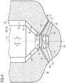
- FIG. 2 a front section of the injection unit 26 of the fuel injector 16 is depicted.
- the nozzle body 36 extends along a central longitudinal axis A and includes the central bore 34.
- a plurality of first injection holes 60 (two of which are shown in Fig. 2 ) and a plurality of second injection holes 62 (two of which are shown in Fig. 2 ) extend through the nozzle tip 38 of the nozzle body 36.
- the first injection holes 60 extend between first inlets 64 and first outlets 66 along first injection hole axes B.
- the second injection holes 62 extend between second inlets 68 and second outlets 70 along second injection hole axes C.
- the first and second inlets 64 and 68 open into a front end section of the central bore 34.
- first inlets 64 are spaced apart from the second inlets 68 in a first direction D of the central longitudinal axis A (a direction from the nozzle tip 38 to the rear end 46 of the needle member 40 (see Fig. 1 )).
- the first and second outlets 66 and 70 open into the combustion chamber of the respective cylinder, in other words, to an exterior of the fuel injector 16.
- the first outlets 66 may open into the second injection holes 62.
- a number of the first injection holes 60 and a number of the second injection holes 62 may depend on various factors, for example flow cross-sectional area, fuel pressure, and engine configuration.
- the number of the first injection holes 60 may be within a range between 1 and 10
- the number of the second injection holes 62 may be within a range between 1 and 10.
- a plurality of first injections holes 60 may be provided.
- the first inlets 64 may be arranged in a distributed manner in a plurality of bands.
- the bands extend circumferentially about the central longitudinal axis A and are spaced apart from each other in the first direction D (do not entirely overlap each other).
- one inlet of the first inlets 64 may be arranged in a first band, whereas another inlet of the first inlets 64 may be arranged in a second band spaced apart from the first band in the first direction D.
- a plurality of second injection holes 62 may be provided.
- the second inlets 68 may be arranged in a distributed manner in a plurality of bands.
- the bands extend circumferentially about the central longitudinal axis A and are spaced apart from each other in the first direction D (do not entirely overlap each other).
- one inlet of the second inlets 68 may be arranged in a third band, whereas another inlet of the second inlets 68 may be arranged in a fourth band spaced apart from the third band in the first direction D.
- the first injection holes 60 are used for injecting the ignition fuel in GFM.
- the first and second injection holes 60 and 62 are used for injecting fuel.
- the first injection holes 60 have a smaller flow cross-sectional area than the second injection holes 62, because considerably less liquid fuel is required in GFM. More generally, the first injection holes 60 together define a total flow cross-sectional area being smaller than a total flow cross-sectional area defined by all second injection holes 62.
- the total flow cross-sectional area of the second injection holes 62 may be greater than the total flow cross-sectional area of the first injection holes 60 by a factor within a range between about 5 and about 100, particularly 5 to 10, more particularly by a factor of about 7.5.
- each first injection hole axis B and the central longitudinal axis A confine a first acute angle ⁇ (also referred to as injection angle of the first injection holes 60).
- each second injection hole axis C and the central longitudinal axis A confine a second acute angle ⁇ (injection angle of the second injection holes 62).
- the first acute angle ⁇ of the first injection holes 60 is smaller than the second acute angle ⁇ of the second injection holes 62.
- the first injection holes 60 are provided for injecting the ignition fuel into the combustion chamber in GFM, which is typically performed before a respective piston reaches the top dead center, for example, about 10° to 20° before the top dead center.
- the fuel injection in LFM is mainly performed by the second injection holes 62, which typically starts when the piston is already closer to the top dead center compared to GFM. Accordingly, at the start of the liquid fuel injection, the combustion chamber may have greater volume in GFM than in LFM.
- the injection angle ⁇ defined by the first injection holes 60 can be made smaller than the injection angle ⁇ defined by the second injection holes 62 while ensuring that the injected fuel is not directly injected onto a heated top face of the piston which is generally undesirable as one skilled in the art will appreciate.
- the injection angle ⁇ may be within a range from 0° to 90°, particularly between 25° and 80°, and/or the injection angle ⁇ may be within a range from 0° to 90°, particularly between 45° and 85°.
- the injection angles ⁇ may differ between different first injection holes 60. In other words, the injection angles ⁇ may be not equal for all first injection holes 60. Additionally or alternatively, the injection angles ⁇ may differ between different second injection holes 62. Stated differently, the injection angles ⁇ may be not equal for all second injection holes 62.
- the two shown first injection holes 60 and the two shown second injection holes 62 are positioned at equal positions with respect to a circumferential direction about the central longitudinal axis A.
- the first injection hole axes B and the second injection hole axes C and the central longitudinal axis A lie in the same plane (the paper plane of Fig. 2 ).
- the first injection holes 60 (the first injection hole axes B) and the second injection holes 62 (the second injection hole axes C) may be arranged spaced apart from each other in the circumferential direction about the central longitudinal axis A.
- first injection hole axis B and the second injection hole axis C and the central longitudinal axis A may not share a common plane.
- Those embodiments may provide an improved rigidity of the needle first end portion 42.
- those embodiments allow to provide the first outlets 66 closer to the second outlets 70 in the second direction E of the central longitudinal axis A.
- those embodiments also allow to provide the first outlets 66 spaced apart from the second outlets 70 in the first direction D of the central longitudinal axis such that the first injection angle ⁇ would be greater than the second injection angle ⁇ , which might be desirable in some embodiments.
- the central bore 34 includes an inner circumferential face 72 extending circumferentially about the central longitudinal axis A.
- the inner circumferential face 72 comprises a first cylindrical sealing face 74, and a first conical sealing face 76.
- the cylindrical sealing face 74 extends along the central longitudinal axis A as a cylinder jacket. Further, the cylindrical sealing face 74 is formed as a circumferential face of a blind hole section 75 of the central bore 34.
- the blind hole section 75 constitutes an end portion of the central bore 34 in a region of the needle tip 38.
- the cylindrical sealing face 74 may have a circular cross-section.
- the first conical sealing face 76 extends along the central longitudinal axis A, and tapers in the second direction E of the central longitudinal axis A opposite the first direction D (the second direction E is a direction from the rear end 46 of the needle member 40 (see Fig. 1 ) to the nozzle tip 38).
- the first conical sealing face 76 is arranged spaced apart from the first inlets 64 of the first injection holes 60 in the first direction D. Additionally or alternatively, for example, at least one of the first inlets 64 may open into the first conical sealing face 76.
- the first cylindrical sealing face 74 is arranged between the first inlets 64 and the second inlets 68 with respect to a direction of the central longitudinal axis A. Specifically, the first inlets 64 are spaced apart from the first cylindrical sealing face 74 in the first direction D of the central longitudinal axis A, and the second inlets 68 are spaced apart from the first cylindrical sealing face 74 in the second direction E of the central longitudinal axis A. Stated differently, the first inlets 64 are displaced from the first cylindrical sealing face 74 in the first direction D, and the second inlets 68 are displaced from the first cylindrical sealing face 74 in the second direction E.
- the needle member 40 includes a second cylindrical sealing face 78 and a second conical sealing face 80.
- the second cylindrical sealing face 78 is positioned adjacent to the second conical sealing face 80.
- the first cylindrical sealing face 74 and the second cylindrical sealing face 78 are configured to mate with each other for providing a sealing engagement between both faces 74 and 78 when the needle member 40 is in a closed position as shown in Fig. 2 , and in an intermediate position as shown in Fig. 3 .
- a distance between both faces measured in a radial direction of the central longitudinal axis may be smaller than about 10 ⁇ m, particularly smaller than about 5 ⁇ m, more particularly about 3 ⁇ m, or even smaller.
- the clearance may be as small as manufacturing and assembly tolerances allow.
- first conical sealing face 76 and the second conical sealing face 80 are configured to mate with each other such that the second conical sealing face 76 sealingly contacts the first conical sealing face when the needle member 40 is in the closed position as shown in Fig. 2 .
- the first conical sealing face 76 serves as a seating face for the needle member 40.
- the at least one second injection hole 62 may include an inlet that is arranged in a cylindrical face extending from the first cylindrical sealing face 74 in the second direction E. Said cylindrical face may have the same diameter or circumference as the first cylindrical sealing face 74.
- the operation of the fuel injector 16 is explained in the following. As noted above, the operation and actuation of the fuel injector 16 is controlled by the control unit 54.
- the fuel injector 16 is in a closed position (first position) as shown in Fig. 2 when no fuel injection into the combustion chamber is desired.
- first position the conical sealing face 80 of the needle member 40 sealingly contacts the conical sealing face 76 of the nozzle body 36.
- liquid fuel present in an annular fuel supply passage 82 of the central bore 34 cannot flow to the first injection holes 60 and second injection holes 62.
- the fuel supply passage 82 is positioned adjacent to the first conical sealing face 76 in the first direction D.
- the needle member 40 is caused to move in the first direction D as shown in Fig. 3 without reaching the fully opened position as shown in Fig. 4 .
- the needle member 40 continuously travels from the fully closed position as shown in Fig. 2 in the direction D as shown in Fig. 3 , but ends travel in the first direction D before reaching the fully opened position as shown in Fig. 4 to return to the fully closed position as shown in Fig. 2 .
- the conical sealing face 80 of the needle member 40 and the conical sealing face 76 of the nozzle body 36 are spaced apart from each other in the first and second directions D and E.
- liquid fuel can flow from the fuel supply passage 82 to the first injection holes 60, and through the first injection holes 60 into the combustion chamber. It is noted that, as shown in Fig. 3 , the first cylindrical sealing face 74 of the nozzle body 36 and the second cylindrical sealing face 78 of the needle member 40 still sealingly contact each other in the intermediate position such that the liquid fuel is blocked from flowing to the second inlets 68 of the second injection holes 62.
- the needle member 40 is caused to move into the fully opened position (second position) as shown in Fig. 4 .
- the fuel supply passage 82 is fluidly connected to both the first injection holes 60 and the second injection holes 62, because neither the sealing faces 76 and 80 are in sealing contact with each other nor the sealing faces 74 and 78 are in sealing contact with each other.
- blocked refers to a situation, in which a fuel flow is substantially blocked, including a small leakage due to, for example, manufacturing and assembling tolerances.
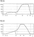
- Fig. 5A shows a first graph indicating a fuel flow injected by the fuel injector 16 (axis of ordinate) over time (axis of abscissa).
- Fig. 5B shows a second graph indicating a lift of the needle member 40 of the fuel injector 16 (axis of ordinate) over time (axis of abscissa) according to the present disclosure.
- the time axes of both Fig. 5A and Fig. 5B correspond to each other.
- Figs. 5A and 5B particularly show a fuel flow rate injected by the fuel injector 16 ( Fig. 5A ) and a lifting motion of the needle member 40 ( Fig. 5B ) obtained in a full lift operation of the fuel injector 16.
- Figs. 5A and 5B operation of the fuel injector 16 during LFM is shown, in which the needle member 40 is caused to slide between the first end position as shown in Fig. 2 and the second end position as shown in Fig. 4 .
- the valve is actuated at a time x1.
- the needle member 40 starts to lift from the closed position as shown in Fig 2 .
- the conical sealing faces 76 and 80 are no longer in sealing engagement, and the conical sealing face 80 of the needle member 40 moves away from the conical sealing face 76 of the nozzle body 36 in the first direction D.
- a liquid fuel from the fuel supply passage 82 of the central bore 34 flows along the sealing faces 76, 80, reaches the first injection holes 60, and is injected via the first injection holes 60 into the combustion chamber.
- the liquid fuel flow rate increases until a time x2. From this time, the fuel flow rate is limited by the flow cross-sectional area of the first injection holes 60.
- the time x2 may be reached at a lift of the needle member 40 of, for example, 10 % of a total lift of the needle member 40.
- the needle member 40 then continues to move away from the first conical sealing face 76 of the nozzle body 36, and the fuel injector 16 continues to inject liquid fuel at a constant flow rate until a time x3. Thereby, the needle member 40 also passes an intermediate position as shown in Fig. 3 .
- actuation of the fuel injector 16 is stopped at or before the time x3.
- solenoid current supplied to the solenoid of the control valve 28 is stopped.
- the needle member 40 then stops travelling away from the first conical sealing face 76, reverses its moving direction to move in the second direction E, and moves back to its closed position as indicated by dashed lines in Figs. 5A and 5B .
- the flow rate reduces until zero when the sealing faces 76 and 80 reach the sealing engagement again.
- the fuel injector 16 is now ready for the next actuation cycle.
- the fuel injector 16 is controlled such that the needle member 40 moves only a part of its full possible lift during one actuation cycle. It was found that needle member lifts within a range between about 15% and about 70%, particularly between about 20% and about 55%, more particularly about 25%, are suitable. However, other partial lifts below 100% of the full possible lift of the needle member 40 are also contemplated.
- liquid fuel from the fuel supply passage 82 of the central bore 34 flows along the sealing faces 76, 80, reaches the first inlets 64 of the first injection holes 60, flows along the sealing faces 74, 78, reaches the second inlets 68 of the second injection holes 62, and is injected via the first and second injection holes 60, 62 into the combustion chamber.
- the liquid fuel flow rate increases until a time x5 shortly after a time x4, at which the needle member 40 reached its second position (see Fig. 4 ).
- the fuel injector is de-energized at a time x6, at which the needle member 40 is caused to move back from the second position (shown in Fig. 4 ) in the second direction E.
- the flow rate starts to decrease at a time x7 until the fuel flow is eventually stopped about a time x8, at which the needle member 40 reached its closed position (first position) as shown in Fig. 2 .
- the fuel injector 16 Upon reaching the closed position, the fuel injector 16 is ready for the next actuation cycle.
- the fuel injector 16 is controlled such that the needle member 40 is caused to move the full possible lift during one actuation cycle.
- the fuel injector 16 may be controlled such that a fuel injection amount in GFM (the first operation mode) may be within a range between 0.25% and 2%, particularly between 0.5% and 1.5%, of a rated full load fuel injection amount in LFM (the second operation mode) during one actuation cycle.
- the first operation mode may be used for pre-injections of a multiple injection strategy including a plurality of injection pulses.
- the fuel injector 16 as disclosed herein is applicable in internal combustion engines where different injection patterns for different operation modes are desired. As described in detail herein, the fuel injector 16 is particularly suitable for use in a dual fuel internal combustion engine configured to operate in LFM and GFM.
Landscapes
- Engineering & Computer Science (AREA)
- Chemical & Material Sciences (AREA)
- Combustion & Propulsion (AREA)
- Mechanical Engineering (AREA)
- General Engineering & Computer Science (AREA)
- Fuel-Injection Apparatus (AREA)
Description
- The present disclosure generally relates to fuel injection systems and methods for operating the same. Particularly, the present disclosure relates to a fuel injector, a dual fuel internal combustion engine, and a method for operating the fuel injector.
- Dual fuel engines are capable of running on gaseous fuel or liquid fuel or a combination of both, thereby allowing to fulfil increased emission standards. Typically, dual fuel engines are operable at least in a liquid fuel mode (LFM) and a gaseous fuel mode (GFM). Herein, a dual fuel engine running on liquid fuel (for example diesel fuel, light fuel oil (LFO), heavy fuel oil (HFO), liquid bio fuel (LBF), or crude oil (CRO)) is referred to as running in the liquid fuel mode (LFM). A dual fuel engine running on gaseous fuel (for example natural gas or biogas) is referred to as running in the gaseous fuel mode (GFM). Exemplary fields of applying dual fuel engines include the global marine industry and power generation systems.
- Dual fuel types of internal combustion engines are usually based on diesel engines. The cycle of an exemplary four stroke diesel engine comprises an intake stroke, a compression stroke, a power stroke, and an exhaust stroke.
- In LFM, dual fuel engines may operate like diesel engines. The dual fuel engine combusts liquid fuel by compressing a mixture of air and fuel (compression stroke) to a point where the liquid fuel is injected and ignited by the heating which accompanies the compression.
- In GFM, the gaseous fuel-air mixture does not self-ignite when it is compressed during the compression stroke. Different types of dual fuel engines were developed to overcome this problem.
- In some types of dual fuel engines, the ignition source may be provided by a spark plug similar to those used in spark ignited engines to trigger the power stroke.
- In other types of dual fuel engines, the ignition source is provided by injecting a small amount of igniting liquid fuel (for example diesel fuel) with a fuel injector into the compressed mixture of air and gaseous fuel at the end of the compression stroke and/or the beginning of the power stroke. Typically, in GFM, an individual ignition fuel injector separate from a liquid fuel injector used for LFM provides the small amount of liquid ignition fuel. Within the compressed mixture of air and gaseous fuel, the small amount of liquid fuel ignites, which in turn ignites the mixture of air and gaseous fuel for the combustion process during the power stroke.
- For example, a fuel injector for a diesel engine is disclosed in
US 6,725,838 of Caterpillar Inc. The fuel injector is capable of injecting fuel for a homogeneous charge compression ignition injection event, which is a conventional injection event. The fuel injector also has a mixed mode that includes a homogeneous charge compression ignition injection and a conventional injection in a single compression stroke for the engine. -
DE 102 07 189 A1 refers to a fuel injector to be used in a Diesel-gas fuel motor. Here, a plurality of first and second injection holes are provided. In dependency of the lifting height of a needle tip only the first injection holes are opened or the first and second injection holes are opened. Similar fuel injectors are disclosed inCA 2 767 247 ,DE 101 09 345 A1 ,JP S59 147864 A JP H03 83373 U EP 1 283 336 A2 . - The present disclosure is directed, at least in part, to improving or overcoming one or more aspects of prior systems.
- In one aspect, a dual fuel internal combustion engine is operable in a liquid fuel mode and in a gaseous fuel mode, wherein a liquid fuel is used in the gaseous fuel mode for igniting a mixture of air and gaseous fuel. The dual fuel internal combustion engine comprises a common rail, at least one fuel injector fluidly connected to the common rail, the fuel injector for a common rail fuel system comprising a nozzle body extending along a central longitudinal axis, and including a central bore having a first cylindrical sealing face circumferentially extending about the central longitudinal axis and further a first conical sealing face circumferentially extending about the central longitudinal axis, the first conical sealing face being spaced apart from at least one first inlet in a first direction. At least one first injection hole extends from a first inlet in the central bore, the first inlet being spaced apart from the first cylindrical sealing face in a first direction along the central longitudinal axis. At least one second injection hole extends from a second inlet in the central bore, the second inlet being spaced apart from the first cylindrical sealing face in a second direction along the central longitudinal axis opposite the first direction. A needle member is slidably arranged in the central bore between a first position and a second position. The needle member has a first end portion which is configured to block or allow a fluid flow from the central bore into the fuel injection holes depending on a position of the needle member and a second end portion which is positioned opposite to the first end portion and is slidably arranged within a collar. The collar and the end portion together define a pressure chamber disposed within the central bore and fluidly connected to the common rail and a valve orifice plate. The needle member includes a second cylindrical sealing face circumferentially extending about the central longitudinal axis and being configured to sealingly contact the first cylindrical sealing face in the first position, and to be spaced apart from the first cylindrical sealing face in the first direction in the second position. Further, the needle member includes a second conical sealing face circumferentially extending about the central longitudinal axis, the second conical sealing face being configured to sealingly contact the first conical sealing face in the first position, and to be spaced apart from the first conical sealing face in the first direction in the second position. A control unit for controling operation of the at least one fuel injector by activating a control valve to open a flow connection from the pressure chamber via the valve orifice plate and a fuel line to a low pressure fuel reservoir. In the gaseous fuel mode, the at least one fuel injector is operated to move the needle member between the first position and an intermediate position only. The intermediate position is situated between the first position and the second position, such that the liquid fuel is injected through the at least one first injection hole only by activating the control valve until a first time such that the needle member stops to move in the first direction at or before the first time is reached. In the liquid fuel mode, the at least one fuel injector is operated to move the needle member between the first position and the second position, such that the liquid fuel is injected through the at least one first injection hole and the at least one second injection hole, by activating the control valve longer than the first time such that the needle member continues to move in the first direction until a second time is reached.
- Other features and aspects of this disclosure will be apparent from the following description and the accompanying drawings.
- The accompanying drawings, which are incorporated herein and constitute a part of the specification, illustrate exemplary embodiments of the disclosure and, together with the description, serve to explain the principles of the disclosure. In the drawings:
-
Fig. 1 shows a schematic drawing of a portion of a dual fuel internal combustion engine, particularly a portion of a fuel system of the dual fuel internal combustion engine, according to the present disclosure. -
Fig. 2 shows a cut view through a nozzle portion of a fuel injector in a closed position, according to the present disclosure. -
Fig. 3 shows a cut view through the nozzle portion of the fuel injector in an intermediate, partially opened position, according to the present disclosure. -
Fig. 4 shows a cut view through the nozzle portion of the fuel injector in a (fully) opened position, according to the present disclosure. -
Fig. 5A shows a first graph indicating a fuel flow rate over time through the fuel injector according to the present disclosure, andFig. 5B shows a second graph indicating a lift of a needle member of the fuel injector over time according to the present disclosure.Fig. 5A and Fig. 5B correspond to each other with respect to the time axes. - The following is a detailed description of exemplary embodiments of the present disclosure. The exemplary embodiments described therein and illustrated in the drawings are intended to teach the principles of the present disclosure, enabling those of ordinary skill in the art to implement and use the present disclosure in many different environments and for many different applications. Therefore, the exemplary embodiments are not intended to be, and should not be considered as, a limiting description of the scope of patent protection. Rather, the scope of patent protection shall be defined by the appended claims.
- The present disclosure is based in part on the realization that although an amount of liquid fuel required in LFM may be considerably larger than an amount of liquid fuel required in GFM, for example by a factor within a range between 50 and 200, it may be possible to use a specifically configured liquid fuel injector for both LFM and GFM. In other words, an additional ignition fuel injector for GFM can be omitted.
- According to the present disclosure, the liquid fuel injector is usable for both LFM and GFM due to a particular configuration of a nozzle portion and a needle member of the fuel injector. Particularly, the fuel injector is configured to provide a small amount of liquid fuel in GFM via at least one first injection hole. The fuel injector is further configured to provide a large amount of liquid fuel in LFM via the at least one first injection hole and at least one second injection hole. That behaviour of the fuel injector is enabled by a specific configuration of a needle tip of the fuel injector's needle member cooperating with a specific configuration of a tip section of the fuel injector's central bore.
- The present disclosure is further based in part on the realization that the fuel injector, which is operable for both LFM and GFM in a dual fuel internal combustion engine, may be also suitable for use in other internal combustion engines where different injection patterns for different operation modes are desired.
- Still further, the present disclosure is based in part on the realization that the fuel injector is particularly suitable for use in large internal combustion engines, more particularly large internal dual fuel internal combustion engines, having a power output of more than 150 kW per cylinder. In those large dual fuel engines, an absolute difference between a large amount of liquid fuel required in LFM, and a small amount of liquid fuel required in GFM may be considerably large. As a result, it is typically not possible to use a conventional fuel injector for both LFM and GFM by controlling the fuel injector to inject liquid fuel for a very short duration in GFM to achieve the required small amount, and to inject liquid fuel for a longer duration in LFM to achieve the required large amount. Instead, those large dual fuel engines conventionally require two separate fuel injectors, one for LFM and the other one for GFM.
- Referring to
Fig. 1 , a portion of a dual fuelinternal combustion engine 10 is depicted. Particularly, a portion of afuel system 12 of the dual fuelinternal combustion engine 10 is shown. - The dual fuel
internal combustion engine 10 may include features not shown, such as air systems, cooling systems, peripheries, drivetrain components, etc. Furthermore, theengine 10 may be of any size, with any number of cylinders, and in any configuration (e.g., "V," in-line, radial, etc.). Theengine 10 may be used to power any machine or other device, including locomotive applications, on-highway trucks or vehicles, off-highway trucks or machines, earth moving equipment, generators, aerospace applications, marine applications, offshore applications, pumps, stationary equipment, or other engine powered applications. - In the shown embodiment, the
dual fuel engine 10 is a large internal combustion engine having a power output of at least 150 kW per cylinder. Thedual fuel engine 10 is capable to run in a liquid fuel mode (LFM), and in a gaseous fuel mode (GFM). In GFM, a liquid fuel, for example diesel fuel, is used as ignition fuel. However, as noted above, it is also contemplated that theengine 10 may be any other type of engine (diesel fuel, gas fuel, etc.), and in any other size, where a fuel injector with different injection patterns for different operation modes is desired. - The
fuel system 12 comprises acommon rail 14, and a plurality of fuel injectors 16 (only one of which is shown inFig. 1 ), one for each cylinder of the dual fuelinternal combustion engine 10. Thefuel injector 16 is accommodated in acylinder head 18 of the dual fuelinternal combustion engine 10. - The
common rail 14 of a common rail system not shown in further detail runs at the outside of thecylinder head 18, although it may also be arranged to run either inside thecylinder head 18 or above thecylinder head 18. Thecommon rail 14 is fluidly connected to thefuel injector 16 via a connection line 20 to provide high pressure fuel (for example diesel fuel, LFO, HFO, LBF, CRO) to thefuel injector 16. For example, the connection line 20 at least partially runs inside thecylinder head 18 and/or near a top of thecylinder head 18. - The
fuel injector 16 comprises an accumulator 22, a flow limiter 24, aninjection unit 26, and acontrol valve 28. - The accumulator 22 is fluidly connected to the
common rail 14 via the connection line 20. The accumulator 22 receives high pressure fuel from thecommon rail 14. In the shown embodiment, the accumulator 22 is housed in thefuel injector 16, however, in other embodiments, the accumulator 22 may be fluidly connected upstream of thefuel injector 16. The accumulator 22 may be an elongated pressure vessel arranged in a back portion of thefuel injector 16, for example extending along a longitudinal axis of thefuel injector 16. - The flow limiter 24 is fluidly connected downstream of the accumulator 22. Specifically, the flow limiter 24 is arranged in a
fuel supply line 30 extending between the high pressure fuel accumulator 22 and theinjection unit 26 of thefuel injector 16. The flow limiter 24 operates to ensure that fuel is injected into the cylinder only when such is desired. For example, the flow limiter 24 may detect changes in flow pressure and may adjust the fuel flow in case of abnormal pressure drop conditions. In one example, the flow limiter 24 blocks supply of liquid fuel from the accumulator 22 to theinjection unit 26 if theinjection unit 26 is leaking. - The
injection unit 26 comprises afuel injector body 32 with a central bore orfuel space 34. Thecentral bore 34 accommodates several elements of theinjection unit 26 as described below. Thefuel injector body 32 further includes anozzle body 36 of anozzle tip 38. Thenozzle body 36 is arranged at a (front) end of thefuel injector body 32. Thenozzle tip 38 faces a combustion chamber of the engine cylinder of thedual fuel engine 10. Thenozzle tip 38 is provided with a plurality of fuel injection holes for injecting liquid fuel into the combustion chamber as described in more detail with reference toFigs. 2 to 4 later on. - The
injection unit 26 further comprises aneedle member 40 arranged centrally in thecentral bore 34. Theneedle member 40 is slidably arranged in thecentral bore 34. A front orfirst end portion 42 of theneedle member 40 is configured to block or allow a fluid flow from thecentral bore 34 into the fuel injection holes depending on a position of the needle member 40 (the needle member first end portion 42). - In some embodiments, the needle member is a one-piece needle member. In other embodiments, the
needle member 40 is formed by an outer needle member surrounding an inner needle member, wherein the outer needle member and the inner needle member may be slidable relative to each other. - Furthermore, in some embodiments, the
needle member 40, specifically the needle memberfirst end portion 42, is formed as a solid body. Stated differently, theneedle member 40 or the needle memberfirst end portion 42 does not include any inner fuel channels. - A
second end portion 46 of theneedle member 40, which is positioned opposite to thefirst end portion 42, is slidably arranged within a collar orbushing 44. Thecollar 44 and theend portion 46 together define a, for example cylindrical,pressure chamber 48 disposed within thecentral bore 34. Thepressure chamber 48 is fluidly connected to the accumulator 22 via thefuel line 30, and avalve orifice plate 50 of theinjection unit 26. Normally, a fuel pressure within thepressure chamber 48 is equal to the full fuel pressure. The fuel pressure of thepressure chamber 48 acts on therear end portion 46 of theneedle member 40, and urges theneedle member 40 in a direction to thenozzle tip 38. Thereby, theneedle member 40 is pushed against a needle member seat, and fuel is inhibited from flowing through the injection holes for injection into the combustion chamber. - A
spring 52 is arranged below thecollar 44 between a shoulder of theneedle member 40 and a front end of thecollar 44 to bias thecollar 44 against thevalve orifice plate 50. Thecentral bore 34 is fluidly connected with the accumulator 22 via thefuel line 30 and the flow limiter 24 such that the full fuel pressure acts on all faces of theneedle member 40. Theneedle member 40 is configured such that the fuel pressure in thecentral bore 34 surrounding theneedle member 40 tends to lift theneedle member 40 upwards away from thenozzle tip 38. However, the force originating from the full fuel pressure acting onto the end of the needle member in thechamber 48 keeps theneedle member 40 closed irrespective of the opposite force created by the fuel pressure acting on theneedle member 40 in thecentral bore 34. - The operation of the injection unit 26 (the fuel injector 16) is controlled by the
control valve 28. Thecontrol valve 28 opens, for example by means of a solenoid, when a fuel injection event is desired. Thecontrol valve 28 is communicatively connected to acontrol unit 54 schematically indicated by a box inFig. 1 . Thecontrol unit 54 may activate thecontrol valve 28 to open a flow connection from thechamber 48 via thevalve orifice plate 50 and afuel line 56 to a lowpressure fuel reservoir 58. Said flow connection reduces the pressure in thechamber 48 such that the fuel pressure in thecentral bore 34 acting onto theneedle member 40 lifts theneedle member 40 to start an injection event. To end an injection event, thecontrol unit 54 allows thecontrol valve 28 to return to its rest position (closed position). For example, a solenoid current supplied to a solenoid of thecontrol valve 28 may be cut off. Then, thecontrol valve 28 blocks the flow from thechamber 48 to the lowpressure fuel reservoir 58. As a result, the flow connection from the accumulator 22 to the lowpressure fuel reservoir 58 via thechamber 48 and thevalve orifice plate 50 is cut off. Thechamber 48 is pressurized again, and theneedle member 40 is urged in its seated position again to block a fuel flow to the injection holes provided in thenozzle tip 38. - Referring to
Fig. 2 , a front section of theinjection unit 26 of thefuel injector 16 is depicted. - As can be seen, the
nozzle body 36 extends along a central longitudinal axis A and includes thecentral bore 34. A plurality of first injection holes 60 (two of which are shown inFig. 2 ) and a plurality of second injection holes 62 (two of which are shown inFig. 2 ) extend through thenozzle tip 38 of thenozzle body 36. Specifically, the first injection holes 60 extend betweenfirst inlets 64 andfirst outlets 66 along first injection hole axes B. Similarly, the second injection holes 62 extend betweensecond inlets 68 andsecond outlets 70 along second injection hole axes C. The first andsecond inlets central bore 34. More specifically, thefirst inlets 64 are spaced apart from thesecond inlets 68 in a first direction D of the central longitudinal axis A (a direction from thenozzle tip 38 to therear end 46 of the needle member 40 (seeFig. 1 )). The first andsecond outlets fuel injector 16. In some embodiment, thefirst outlets 66 may open into the second injection holes 62. - As one skilled in the art will appreciate, a number of the first injection holes 60 and a number of the second injection holes 62 may depend on various factors, for example flow cross-sectional area, fuel pressure, and engine configuration. For example, the number of the first injection holes 60 may be within a range between 1 and 10, and/or the number of the second injection holes 62 may be within a range between 1 and 10.
- In some embodiments, a plurality of first injections holes 60 may be provided. The
first inlets 64 may be arranged in a distributed manner in a plurality of bands. The bands extend circumferentially about the central longitudinal axis A and are spaced apart from each other in the first direction D (do not entirely overlap each other). For example, one inlet of thefirst inlets 64 may be arranged in a first band, whereas another inlet of thefirst inlets 64 may be arranged in a second band spaced apart from the first band in the first direction D. - Similarly, in some embodiments, a plurality of second injection holes 62 may be provided. The
second inlets 68 may be arranged in a distributed manner in a plurality of bands. The bands extend circumferentially about the central longitudinal axis A and are spaced apart from each other in the first direction D (do not entirely overlap each other). For example, one inlet of thesecond inlets 68 may be arranged in a third band, whereas another inlet of thesecond inlets 68 may be arranged in a fourth band spaced apart from the third band in the first direction D. - As is described in more detail later on with reference to
Figs. 2 to 5 , the first injection holes 60 are used for injecting the ignition fuel in GFM. On the other hand, in LFM, the first and second injection holes 60 and 62 are used for injecting fuel. - As can be seen from the schematic drawing of
Fig. 2 , the first injection holes 60 have a smaller flow cross-sectional area than the second injection holes 62, because considerably less liquid fuel is required in GFM. More generally, the first injection holes 60 together define a total flow cross-sectional area being smaller than a total flow cross-sectional area defined by all second injection holes 62. For example, the total flow cross-sectional area of the second injection holes 62 may be greater than the total flow cross-sectional area of the first injection holes 60 by a factor within a range between about 5 and about 100, particularly 5 to 10, more particularly by a factor of about 7.5. - Further, each first injection hole axis B and the central longitudinal axis A confine a first acute angle α (also referred to as injection angle of the first injection holes 60). Similarly, each second injection hole axis C and the central longitudinal axis A confine a second acute angle β (injection angle of the second injection holes 62).
- In some embodiments, for example as shown in
Fig. 2 , the first acute angle α of the first injection holes 60 is smaller than the second acute angle β of the second injection holes 62. The reason is that the first injection holes 60 are provided for injecting the ignition fuel into the combustion chamber in GFM, which is typically performed before a respective piston reaches the top dead center, for example, about 10° to 20° before the top dead center. In contrast, the fuel injection in LFM is mainly performed by the second injection holes 62, which typically starts when the piston is already closer to the top dead center compared to GFM. Accordingly, at the start of the liquid fuel injection, the combustion chamber may have greater volume in GFM than in LFM. Therefore, the injection angle α defined by the first injection holes 60 can be made smaller than the injection angle β defined by the second injection holes 62 while ensuring that the injected fuel is not directly injected onto a heated top face of the piston which is generally undesirable as one skilled in the art will appreciate. For example, the injection angle α may be within a range from 0° to 90°, particularly between 25° and 80°, and/or the injection angle β may be within a range from 0° to 90°, particularly between 45° and 85°. - In some embodiments, the injection angles α may differ between different first injection holes 60. In other words, the injection angles α may be not equal for all first injection holes 60. Additionally or alternatively, the injection angles β may differ between different second injection holes 62. Stated differently, the injection angles β may be not equal for all second injection holes 62.
- Furthermore, in the embodiment depicted in
Fig. 2 , the two shown first injection holes 60 and the two shown second injection holes 62 are positioned at equal positions with respect to a circumferential direction about the central longitudinal axis A. In other words, the first injection hole axes B and the second injection hole axes C and the central longitudinal axis A lie in the same plane (the paper plane ofFig. 2 ). However, in some embodiments, the first injection holes 60 (the first injection hole axes B) and the second injection holes 62 (the second injection hole axes C) may be arranged spaced apart from each other in the circumferential direction about the central longitudinal axis A. Stated differently, the first injection hole axis B and the second injection hole axis C and the central longitudinal axis A may not share a common plane. Those embodiments may provide an improved rigidity of the needlefirst end portion 42. Additionally, those embodiments allow to provide thefirst outlets 66 closer to thesecond outlets 70 in the second direction E of the central longitudinal axis A. Still further, those embodiments also allow to provide thefirst outlets 66 spaced apart from thesecond outlets 70 in the first direction D of the central longitudinal axis such that the first injection angle α would be greater than the second injection angle β, which might be desirable in some embodiments. - The
central bore 34 includes an innercircumferential face 72 extending circumferentially about the central longitudinal axis A. The innercircumferential face 72 comprises a firstcylindrical sealing face 74, and a firstconical sealing face 76. Thecylindrical sealing face 74 extends along the central longitudinal axis A as a cylinder jacket. Further, thecylindrical sealing face 74 is formed as a circumferential face of ablind hole section 75 of thecentral bore 34. Theblind hole section 75 constitutes an end portion of thecentral bore 34 in a region of theneedle tip 38. For example, thecylindrical sealing face 74 may have a circular cross-section. The firstconical sealing face 76 extends along the central longitudinal axis A, and tapers in the second direction E of the central longitudinal axis A opposite the first direction D (the second direction E is a direction from therear end 46 of the needle member 40 (seeFig. 1 ) to the nozzle tip 38). - In the shown embodiment, the first
conical sealing face 76 is arranged spaced apart from thefirst inlets 64 of the first injection holes 60 in the first direction D. Additionally or alternatively, for example, at least one of thefirst inlets 64 may open into the firstconical sealing face 76. - The first
cylindrical sealing face 74 is arranged between thefirst inlets 64 and thesecond inlets 68 with respect to a direction of the central longitudinal axis A. Specifically, thefirst inlets 64 are spaced apart from the firstcylindrical sealing face 74 in the first direction D of the central longitudinal axis A, and thesecond inlets 68 are spaced apart from the firstcylindrical sealing face 74 in the second direction E of the central longitudinal axis A. Stated differently, thefirst inlets 64 are displaced from the firstcylindrical sealing face 74 in the first direction D, and thesecond inlets 68 are displaced from the firstcylindrical sealing face 74 in the second direction E. - Similarly, the
needle member 40 includes a secondcylindrical sealing face 78 and a secondconical sealing face 80. In the shown embodiment, the secondcylindrical sealing face 78 is positioned adjacent to the secondconical sealing face 80. - The first
cylindrical sealing face 74 and the secondcylindrical sealing face 78 are configured to mate with each other for providing a sealing engagement between both faces 74 and 78 when theneedle member 40 is in a closed position as shown inFig. 2 , and in an intermediate position as shown inFig. 3 . For obtaining the desired sealing effect while allowing a smooth sliding movement between both faces 74, 78 until both faces 74, 78 eventually lose contact (disengage), for example, as shown inFig. 4 , a distance between both faces measured in a radial direction of the central longitudinal axis (in a plane perpendicular to the central longitudinal axis A) may be smaller than about 10 µm, particularly smaller than about 5 µm, more particularly about 3 µm, or even smaller. In some embodiments, the clearance may be as small as manufacturing and assembly tolerances allow. - Similarly, the first
conical sealing face 76 and the secondconical sealing face 80 are configured to mate with each other such that the secondconical sealing face 76 sealingly contacts the first conical sealing face when theneedle member 40 is in the closed position as shown inFig. 2 . The firstconical sealing face 76 serves as a seating face for theneedle member 40. - In some embodiments, the at least one
second injection hole 62 may include an inlet that is arranged in a cylindrical face extending from the firstcylindrical sealing face 74 in the second direction E. Said cylindrical face may have the same diameter or circumference as the firstcylindrical sealing face 74. - Referring to
Figs. 1 to 5 , the operation of thefuel injector 16 is explained in the following. As noted above, the operation and actuation of thefuel injector 16 is controlled by thecontrol unit 54. - The
fuel injector 16 is in a closed position (first position) as shown inFig. 2 when no fuel injection into the combustion chamber is desired. In the closed position, theconical sealing face 80 of theneedle member 40 sealingly contacts the conical sealing face 76 of thenozzle body 36. As a result, liquid fuel present in an annularfuel supply passage 82 of thecentral bore 34 cannot flow to the first injection holes 60 and second injection holes 62. Thefuel supply passage 82 is positioned adjacent to the firstconical sealing face 76 in the first direction D. - In case a liquid fuel injection through the first injection holes 60 only is desired (for example in GFM), the
needle member 40 is caused to move in the first direction D as shown inFig. 3 without reaching the fully opened position as shown inFig. 4 . In other words, theneedle member 40 continuously travels from the fully closed position as shown inFig. 2 in the direction D as shown inFig. 3 , but ends travel in the first direction D before reaching the fully opened position as shown inFig. 4 to return to the fully closed position as shown inFig. 2 . In an intermediate position (third position) as shown inFig. 3 , theconical sealing face 80 of theneedle member 40 and the conical sealing face 76 of thenozzle body 36 are spaced apart from each other in the first and second directions D and E. Thus, liquid fuel can flow from thefuel supply passage 82 to the first injection holes 60, and through the first injection holes 60 into the combustion chamber. It is noted that, as shown inFig. 3 , the firstcylindrical sealing face 74 of thenozzle body 36 and the secondcylindrical sealing face 78 of theneedle member 40 still sealingly contact each other in the intermediate position such that the liquid fuel is blocked from flowing to thesecond inlets 68 of the second injection holes 62. - In case a liquid fuel injection through the first injection holes 60 and the second injection holes 62 is desired (for example in LFM), the
needle member 40 is caused to move into the fully opened position (second position) as shown inFig. 4 . Here, thefuel supply passage 82 is fluidly connected to both the first injection holes 60 and the second injection holes 62, because neither the sealing faces 76 and 80 are in sealing contact with each other nor the sealing faces 74 and 78 are in sealing contact with each other. - As used herein, the term "blocked" refers to a situation, in which a fuel flow is substantially blocked, including a small leakage due to, for example, manufacturing and assembling tolerances.
- The operation of the
fuel injector 16 is also shown inFigs. 5A and 5B. Fig. 5A shows a first graph indicating a fuel flow injected by the fuel injector 16 (axis of ordinate) over time (axis of abscissa).Fig. 5B shows a second graph indicating a lift of theneedle member 40 of the fuel injector 16 (axis of ordinate) over time (axis of abscissa) according to the present disclosure. The time axes of bothFig. 5A and Fig. 5B correspond to each other. -
Figs. 5A and 5B particularly show a fuel flow rate injected by the fuel injector 16 (Fig. 5A ) and a lifting motion of the needle member 40 (Fig. 5B ) obtained in a full lift operation of thefuel injector 16. In other words, inFigs. 5A and 5B , operation of thefuel injector 16 during LFM is shown, in which theneedle member 40 is caused to slide between the first end position as shown inFig. 2 and the second end position as shown inFig. 4 . - The valve is actuated at a time x1. The
needle member 40 starts to lift from the closed position as shown inFig 2 . The conical sealing faces 76 and 80 are no longer in sealing engagement, and the conical sealing face 80 of theneedle member 40 moves away from the conical sealing face 76 of thenozzle body 36 in the first direction D. A liquid fuel from thefuel supply passage 82 of thecentral bore 34 flows along the sealing faces 76, 80, reaches the first injection holes 60, and is injected via the first injection holes 60 into the combustion chamber. The liquid fuel flow rate increases until a time x2. From this time, the fuel flow rate is limited by the flow cross-sectional area of the first injection holes 60. The time x2 may be reached at a lift of theneedle member 40 of, for example, 10 % of a total lift of theneedle member 40. - The
needle member 40 then continues to move away from the firstconical sealing face 76 of thenozzle body 36, and thefuel injector 16 continues to inject liquid fuel at a constant flow rate until a time x3. Thereby, theneedle member 40 also passes an intermediate position as shown inFig. 3 . - In case the
engine 10 is operated in GFM, actuation of thefuel injector 16 is stopped at or before the time x3. For example, solenoid current supplied to the solenoid of thecontrol valve 28 is stopped. Theneedle member 40 then stops travelling away from the firstconical sealing face 76, reverses its moving direction to move in the second direction E, and moves back to its closed position as indicated by dashed lines inFigs. 5A and 5B . As a result, the flow rate reduces until zero when the sealing faces 76 and 80 reach the sealing engagement again. Thefuel injector 16 is now ready for the next actuation cycle. It should be noted, that during GFM (more generally, a first operation mode of thefuel injector 16 and the engine 10), thefuel injector 16 is controlled such that theneedle member 40 moves only a part of its full possible lift during one actuation cycle. It was found that needle member lifts within a range between about 15% and about 70%, particularly between about 20% and about 55%, more particularly about 25%, are suitable. However, other partial lifts below 100% of the full possible lift of theneedle member 40 are also contemplated. - In case the
engine 10 is operated in LFM (shown as solid lines inFigs. 5A and 5B ), actuation of thefuel injector 16 is not stopped at or before the time x3. Instead, thecontrol valve 28 continues to cause theneedle member 40 two move in the first direction D. As a result, the first and second cylindrical sealing faces 74 and 78 are no longer in sealing engagement from the time x3 on. Thus, fuel from thefuel supply passage 82 is allowed to flow to the second injection holes 62, too. Specifically, liquid fuel from thefuel supply passage 82 of thecentral bore 34 flows along the sealing faces 76, 80, reaches thefirst inlets 64 of the first injection holes 60, flows along the sealing faces 74, 78, reaches thesecond inlets 68 of the second injection holes 62, and is injected via the first and second injection holes 60, 62 into the combustion chamber. The liquid fuel flow rate increases until a time x5 shortly after a time x4, at which theneedle member 40 reached its second position (seeFig. 4 ). The fuel injector is de-energized at a time x6, at which theneedle member 40 is caused to move back from the second position (shown inFig. 4 ) in the second direction E. As a result, the flow rate starts to decrease at a time x7 until the fuel flow is eventually stopped about a time x8, at which theneedle member 40 reached its closed position (first position) as shown inFig. 2 . Upon reaching the closed position, thefuel injector 16 is ready for the next actuation cycle. - Again, it should be noted that during LFM (more generally, a second operation mode of the
fuel injector 16 and the engine 10), thefuel injector 16 is controlled such that theneedle member 40 is caused to move the full possible lift during one actuation cycle. - The
fuel injector 16 may be controlled such that a fuel injection amount in GFM (the first operation mode) may be within a range between 0.25% and 2%, particularly between 0.5% and 1.5%, of a rated full load fuel injection amount in LFM (the second operation mode) during one actuation cycle. - In some embodiments, the first operation mode may be used for pre-injections of a multiple injection strategy including a plurality of injection pulses.
- The
fuel injector 16 as disclosed herein is applicable in internal combustion engines where different injection patterns for different operation modes are desired. As described in detail herein, thefuel injector 16 is particularly suitable for use in a dual fuel internal combustion engine configured to operate in LFM and GFM. - Terms such as "about", "around", "approximately", or "substantially" as used herein when referring to a measurable value such as a parameter, an amount, a temporal duration, and the like, is meant to encompass variations of ±10% or less, preferably ±5% or less, more preferably ±1 % or less, and still more preferably ±0.1% or less of and from the specified value, insofar as such variations are appropriate to perform in the disclosed invention. It is to be understood that the value to which the modifier "about" refers is itself also specifically, and preferably, disclosed. The recitation of numerical ranges by endpoints includes all numbers and fractions subsumed within the respective ranges, as well as the recited endpoints.
- Although the preferred embodiments of this invention have been described herein, improvements and modifications may be incorporated without departing from the scope of the following claims.
Claims (11)
- A dual fuel internal combustion engine (10) operable in a liquid fuel mode and in a gaseous fuel mode, wherein a liquid fuel is used in the gaseous fuel mode for igniting a mixture of air and gaseous fuel, the dual fuel internal combustion engine (10) comprising:a common rail (14);at least one fuel injector (16) fluidly connected to the common rail (14), the fuel injector (16), comprising:a nozzle body (36) extending along a central longitudinal axis (A), and including a central bore (34) having a first cylindrical sealing face (74) circumferentially extending about the central longitudinal axis (A) and further a first conical sealing face (76) circumferentially extending about the central longitudinal axis (A), the first conical sealing face (76) being spaced apart from at least one first inlet (64) in a first direction (D);at least one first injection hole (60) extending from a first inlet (64) in the central bore (34), the first inlet (64) being spaced apart from the first cylindrical sealing face (74) in a first direction (D) along the central longitudinal axis (A); andat least one second injection hole (62) extending from a second inlet (68) in the central bore (34), the second inlet (68) being spaced apart from the first cylindrical sealing face (74) in a second direction (E) along the central longitudinal axis (A) opposite the first direction (D); anda needle member (40) slidably arranged in the central bore (34) between a first position and a second position, the needle member (40) having a first end portion (42) which is configured to block or allow a fluid flow from the central bore (34) into the fuel injection holes (60, 62) depending on a position of the needle member (40) and a second end portion (46) which is positioned opposite to the first end portion (42) and is slidably arranged within a collar (44), wherein the collar (44) and the end portion (46) together define a pressure chamber (48) disposed within the central bore (34) and fluidly connected to the common rail (14) and a valve orifice plate (50), the needle member (40) including:a second cylindrical sealing face (78) circumferentially extending about the central longitudinal axis (A) and being configured to sealingly contact the first cylindrical sealing face (74) in the first position, and to be spaced apart from the first cylindrical sealing face (74) in the first direction (D) in the second position; anda second conical sealing face (80) circumferentially extending about the central longitudinal axis (A), the second conical sealing face (80) being configured to sealingly contact the first conical sealing face (76) in the first position, and to be spaced apart from the first conical sealing face (76) in the first direction (D) in the second position; anda control unit (54) for controlling operation of the at least one fuel injector (16) by activating a control valve (28) to open a flow connection from the pressure chamber (48) via the valve orifice plate (50) and a fuel line (56) to a low pressure fuel reservoir (58),wherein, in the gaseous fuel mode, the at least one fuel injector (16) is operated to move the needle member (40) between the first position and an intermediate position only, the intermediate position being situated between the first position and the second position, such that the liquid fuel is injected through the at least one first injection hole (60) only, by activating the control valve (28) until a first time (x3) such that the needle member (40) stops to move in the first direction (D) at or before the first time (x3) is reached; andwherein, in the liquid fuel mode, the at least one fuel injector (16) is operated to move the needle member (40) between the first position and the second position, such that the liquid fuel is injected through the at least one first injection hole (60) and the at least one second injection hole (62), by activating the control valve (28) longer than the first time (x3) such that the needle member (40) continues to move in the first direction (D) until a second time (x6) is reached.
- The dual fuel internal combustion engine (10) of claim 1, wherein:the needle member (40) is a one-piece needle member; and/orthe needle member (40) is formed as a solid body.
- The dual fuel internal combustion engine (10) of any one of the preceding claims, wherein the first injection hole (60) has a smaller flow cross-sectional area than the second injection hole (62).
- The dual fuel internal combustion engine (10) of any one of the preceding claims, wherein
the first injection holes (60) together define a first total flow cross-sectional area; and
the second injection holes (62) together define a second total flow cross-sectional area greater than the first total flow cross-sectional area. - The dual internal combustion engine (10) of claim 4, wherein the second total flow cross-sectional area is greater than the first total flow cross-sectional area by a factor within a range between about 5 and about 100.
- The dual fuel internal combustion engine (10) of any one of the preceding claims, wherein
at least one first injection hole (60) extends along a respective first injection hole axis (B) intersecting the central longitudinal axis (A) to define a first acute angle (α) therebetween;
at least one second injection hole (62) extends along a respective second injection hole axis (C) intersecting the central longitudinal axis (A) to define a second acute angle (β) therebetween, the second acute angle (β) being greater than the first acute angle (α). - The dual fuel internal combustion engine (10) of any one of the preceding claims, wherein the at least one first injection hole (60) is arranged spaced apart from the at least one second injection hole (62) in a circumferential direction about the central longitudinal axis (A).
- The dual fuel internal combustion engine (10) of any one of the preceding claims, wherein a plurality of first injections holes (60) is provided, and the first inlets (64) of the first injection holes (60) are arranged in a distributed manner in a plurality of bands, which extend circumferentially about the central longitudinal axis (A) and are spaced apart from each other in the first direction (D).
- The dual fuel internal combustion engine (10) of any one of the preceding claims, wherein the central bore (34) includes a blind hole section (75) at one end thereof, and the first cylindrical sealing face (74) is formed as a circumferential face of the blind hole section (75).
- The dual fuel internal combustion engine (10) of any one of the preceding claims, wherein:in the first position, a fuel flow is blocked from flowing through the at least one first injection hole (60) and the at least one second injection hole (62); and/orin the second position, a fuel is allowed to flow through the at least one first injection hole (60) and the at least one second injection hole (62); and/orin a third position situated between the first position and the second position, the fuel is allowed to flow through the at least one first injection hole (60) and blocked from flowing through the at least one second injection hole (62).
- The dual fuel internal combustion engine (10) of any one of the preceding claims, wherein the intermediate position is defined by a lift of the needle member (40) within a range between 15% and 70%, particularly between 20% and 55% of a full lift defined between the first position and the second position.
Priority Applications (1)
| Application Number | Priority Date | Filing Date | Title |
|---|---|---|---|
| EP16172747.4A EP3252301B1 (en) | 2016-06-02 | 2016-06-02 | Fuel injector for a dual fuel engine |
Applications Claiming Priority (1)
| Application Number | Priority Date | Filing Date | Title |
|---|---|---|---|
| EP16172747.4A EP3252301B1 (en) | 2016-06-02 | 2016-06-02 | Fuel injector for a dual fuel engine |
Publications (2)
| Publication Number | Publication Date |
|---|---|
| EP3252301A1 EP3252301A1 (en) | 2017-12-06 |
| EP3252301B1 true EP3252301B1 (en) | 2020-12-02 |
Family
ID=56098129
Family Applications (1)
| Application Number | Title | Priority Date | Filing Date |
|---|---|---|---|
| EP16172747.4A Active EP3252301B1 (en) | 2016-06-02 | 2016-06-02 | Fuel injector for a dual fuel engine |
Country Status (1)
| Country | Link |
|---|---|
| EP (1) | EP3252301B1 (en) |
Families Citing this family (6)
| Publication number | Priority date | Publication date | Assignee | Title |
|---|---|---|---|---|
| DE102018113660A1 (en) * | 2018-06-08 | 2019-12-12 | Liebherr-Components Deggendorf Gmbh | Nozzle for injecting fuel |
| DE102019210631A1 (en) * | 2019-07-18 | 2021-01-21 | Robert Bosch Gmbh | Fuel injector for internal combustion engines |
| EP4081348A4 (en) * | 2019-12-23 | 2023-12-27 | QuantLogic Corporation | A fuel injector adaptive for single and dual fuel injection |
| CN113187637B (en) * | 2021-04-06 | 2022-09-23 | 大连理工大学 | Composite hole nozzle with intersection structure |
| GB2616442A (en) * | 2022-03-08 | 2023-09-13 | Delphi Tech Ip Ltd | Injector Nozzle |
| JP2024049351A (en) * | 2022-09-28 | 2024-04-09 | マン・エナジー・ソリューションズ・エスイー | Injection nozzle for dual-fuel engine, dual-fuel engine, and method for operating the same |
Citations (1)
| Publication number | Priority date | Publication date | Assignee | Title |
|---|---|---|---|---|
| DE102006033878A1 (en) * | 2006-07-21 | 2008-01-31 | Siemens Ag | Nozzle assembly for injecting valve, has nozzle body and needle arranged to release fluid flow to row of injecting holes only by needle in cooperation with wall of recess downstream to passage in position range of needle |
Family Cites Families (8)
| Publication number | Priority date | Publication date | Assignee | Title |
|---|---|---|---|---|
| JPS59147864A (en) * | 1983-02-12 | 1984-08-24 | Toyota Motor Corp | Fuel injection valve for diesel engine |
| JPH0383373U (en) * | 1989-12-18 | 1991-08-23 | ||
| JP4221898B2 (en) * | 2000-02-29 | 2009-02-12 | 株式会社デンソー | Fuel injection nozzle |
| DE10207189A1 (en) * | 2001-03-03 | 2002-09-12 | Fev Motorentech Gmbh | Switchable injection device for injecting different fuel quantities, has nozzle holes in only a first plane or in two planes exposed to fuel depending on the valve needle's stroke |
| EP1283336B1 (en) * | 2001-08-06 | 2007-04-11 | Toyota Jidosha Kabushiki Kaisha | Internal combustion engine |
| US6725838B2 (en) | 2001-10-09 | 2004-04-27 | Caterpillar Inc | Fuel injector having dual mode capabilities and engine using same |
| US7032566B2 (en) * | 2003-05-30 | 2006-04-25 | Caterpillar Inc. | Fuel injector nozzle for an internal combustion engine |
| CA2767247C (en) * | 2012-02-07 | 2014-03-25 | Westport Power Inc. | Apparatus and method for igniting a gaseous fuel in a direct injection internal combustion engine |
-
2016
- 2016-06-02 EP EP16172747.4A patent/EP3252301B1/en active Active
Patent Citations (1)
| Publication number | Priority date | Publication date | Assignee | Title |
|---|---|---|---|---|
| DE102006033878A1 (en) * | 2006-07-21 | 2008-01-31 | Siemens Ag | Nozzle assembly for injecting valve, has nozzle body and needle arranged to release fluid flow to row of injecting holes only by needle in cooperation with wall of recess downstream to passage in position range of needle |
Also Published As
| Publication number | Publication date |
|---|---|
| EP3252301A1 (en) | 2017-12-06 |
Similar Documents
| Publication | Publication Date | Title |
|---|---|---|
| EP3252301B1 (en) | Fuel injector for a dual fuel engine | |
| CN103782021B (en) | For the fuel injector of double fuel common rail system | |
| EP2487353B1 (en) | Dual fuel common rail system | |
| US7216632B2 (en) | Fuel injection valve | |
| US9359985B2 (en) | Fluid injector actuator with resilient armature overtravel feature | |
| US20060081722A1 (en) | Gaseous fuel injector for internal combustion engine | |
| US8726884B2 (en) | Quill assembly for a dual fuel common rail fuel system | |
| US9903325B2 (en) | Dual fuel fuel-injector | |
| JP2020037945A (en) | Injection device and method for using injection device | |
| EP2302197A1 (en) | Fuel injection valve and fuel injection device | |
| US11859583B2 (en) | Fuel injector having dual solenoid control valves | |
| AU2014204548A1 (en) | Dual fuel system for internal combustion engine and leakage limiting seal strategy for same | |
| KR102042308B1 (en) | A fuel system for a gas operated internal combustion piston engine | |
| DE102016110112A1 (en) | Fuel injector | |
| US7886718B2 (en) | Fuel injector having integral body guide and nozzle case for pressure containment | |
| KR20140032417A (en) | Injection valve for internal combustion engines | |
| JP5152220B2 (en) | Fuel injection device | |
| US20160230728A1 (en) | Plunger And Fluid-Line System | |
| JP6384366B2 (en) | Fuel injection device | |
| EP2703631B1 (en) | Injector configuration of a cylinder head of a dual fuel internal combustion engine | |
| EP2984327B1 (en) | A dual fuel injection unit and dual fuel feeding arrangement | |
| US11828257B2 (en) | Injector apparatus | |
| US11828256B2 (en) | Injector apparatus | |
| EP3513056B1 (en) | Fuel injector and piston bowl | |
| JP6457797B2 (en) | Fuel injection nozzle |
Legal Events
| Date | Code | Title | Description |
|---|---|---|---|
| PUAI | Public reference made under article 153(3) epc to a published international application that has entered the european phase |
Free format text: ORIGINAL CODE: 0009012 |
|
| STAA | Information on the status of an ep patent application or granted ep patent |
Free format text: STATUS: THE APPLICATION HAS BEEN PUBLISHED |
|
| AK | Designated contracting states |
Kind code of ref document: A1 Designated state(s): AL AT BE BG CH CY CZ DE DK EE ES FI FR GB GR HR HU IE IS IT LI LT LU LV MC MK MT NL NO PL PT RO RS SE SI SK SM TR |
|
| AX | Request for extension of the european patent |
Extension state: BA ME |
|
| STAA | Information on the status of an ep patent application or granted ep patent |
Free format text: STATUS: REQUEST FOR EXAMINATION WAS MADE |
|
| 17P | Request for examination filed |
Effective date: 20180606 |
|
| RBV | Designated contracting states (corrected) |
Designated state(s): AL AT BE BG CH CY CZ DE DK EE ES FI FR GB GR HR HU IE IS IT LI LT LU LV MC MK MT NL NO PL PT RO RS SE SI SK SM TR |
|
| STAA | Information on the status of an ep patent application or granted ep patent |
Free format text: STATUS: EXAMINATION IS IN PROGRESS |
|
| 17Q | First examination report despatched |
Effective date: 20190125 |
|
| GRAP | Despatch of communication of intention to grant a patent |
Free format text: ORIGINAL CODE: EPIDOSNIGR1 |
|
| STAA | Information on the status of an ep patent application or granted ep patent |
Free format text: STATUS: GRANT OF PATENT IS INTENDED |
|
| RIC1 | Information provided on ipc code assigned before grant |
Ipc: F02M 43/04 20060101ALN20200612BHEP Ipc: F02M 61/18 20060101AFI20200612BHEP Ipc: F02M 45/08 20060101ALI20200612BHEP |
|
| INTG | Intention to grant announced |
Effective date: 20200703 |
|
| GRAS | Grant fee paid |
Free format text: ORIGINAL CODE: EPIDOSNIGR3 |
|
| GRAA | (expected) grant |
Free format text: ORIGINAL CODE: 0009210 |
|
| STAA | Information on the status of an ep patent application or granted ep patent |
Free format text: STATUS: THE PATENT HAS BEEN GRANTED |
|
| AK | Designated contracting states |
Kind code of ref document: B1 Designated state(s): AL AT BE BG CH CY CZ DE DK EE ES FI FR GB GR HR HU IE IS IT LI LT LU LV MC MK MT NL NO PL PT RO RS SE SI SK SM TR |
|
| REG | Reference to a national code |
Ref country code: GB Ref legal event code: FG4D |
|
| REG | Reference to a national code |
Ref country code: AT Ref legal event code: REF Ref document number: 1341193 Country of ref document: AT Kind code of ref document: T Effective date: 20201215 Ref country code: CH Ref legal event code: EP |
|
| REG | Reference to a national code |
Ref country code: IE Ref legal event code: FG4D |
|
| REG | Reference to a national code |
Ref country code: DE Ref legal event code: R096 Ref document number: 602016048915 Country of ref document: DE |
|
| PG25 | Lapsed in a contracting state [announced via postgrant information from national office to epo] |
Ref country code: RS Free format text: LAPSE BECAUSE OF FAILURE TO SUBMIT A TRANSLATION OF THE DESCRIPTION OR TO PAY THE FEE WITHIN THE PRESCRIBED TIME-LIMIT Effective date: 20201202 Ref country code: NO Free format text: LAPSE BECAUSE OF FAILURE TO SUBMIT A TRANSLATION OF THE DESCRIPTION OR TO PAY THE FEE WITHIN THE PRESCRIBED TIME-LIMIT Effective date: 20210302 Ref country code: GR Free format text: LAPSE BECAUSE OF FAILURE TO SUBMIT A TRANSLATION OF THE DESCRIPTION OR TO PAY THE FEE WITHIN THE PRESCRIBED TIME-LIMIT Effective date: 20210303 Ref country code: FI Free format text: LAPSE BECAUSE OF FAILURE TO SUBMIT A TRANSLATION OF THE DESCRIPTION OR TO PAY THE FEE WITHIN THE PRESCRIBED TIME-LIMIT Effective date: 20201202 |
|
| REG | Reference to a national code |
Ref country code: NL Ref legal event code: MP Effective date: 20201202 |
|
| REG | Reference to a national code |
Ref country code: AT Ref legal event code: MK05 Ref document number: 1341193 Country of ref document: AT Kind code of ref document: T Effective date: 20201202 |
|
| PG25 | Lapsed in a contracting state [announced via postgrant information from national office to epo] |
Ref country code: BG Free format text: LAPSE BECAUSE OF FAILURE TO SUBMIT A TRANSLATION OF THE DESCRIPTION OR TO PAY THE FEE WITHIN THE PRESCRIBED TIME-LIMIT Effective date: 20210302 Ref country code: LV Free format text: LAPSE BECAUSE OF FAILURE TO SUBMIT A TRANSLATION OF THE DESCRIPTION OR TO PAY THE FEE WITHIN THE PRESCRIBED TIME-LIMIT Effective date: 20201202 Ref country code: SE Free format text: LAPSE BECAUSE OF FAILURE TO SUBMIT A TRANSLATION OF THE DESCRIPTION OR TO PAY THE FEE WITHIN THE PRESCRIBED TIME-LIMIT Effective date: 20201202 Ref country code: PL Free format text: LAPSE BECAUSE OF FAILURE TO SUBMIT A TRANSLATION OF THE DESCRIPTION OR TO PAY THE FEE WITHIN THE PRESCRIBED TIME-LIMIT Effective date: 20201202 |
|
| PG25 | Lapsed in a contracting state [announced via postgrant information from national office to epo] |
Ref country code: NL Free format text: LAPSE BECAUSE OF FAILURE TO SUBMIT A TRANSLATION OF THE DESCRIPTION OR TO PAY THE FEE WITHIN THE PRESCRIBED TIME-LIMIT Effective date: 20201202 Ref country code: HR Free format text: LAPSE BECAUSE OF FAILURE TO SUBMIT A TRANSLATION OF THE DESCRIPTION OR TO PAY THE FEE WITHIN THE PRESCRIBED TIME-LIMIT Effective date: 20201202 |
|
| REG | Reference to a national code |
Ref country code: LT Ref legal event code: MG9D |
|
| PG25 | Lapsed in a contracting state [announced via postgrant information from national office to epo] |
Ref country code: SK Free format text: LAPSE BECAUSE OF FAILURE TO SUBMIT A TRANSLATION OF THE DESCRIPTION OR TO PAY THE FEE WITHIN THE PRESCRIBED TIME-LIMIT Effective date: 20201202 Ref country code: PT Free format text: LAPSE BECAUSE OF FAILURE TO SUBMIT A TRANSLATION OF THE DESCRIPTION OR TO PAY THE FEE WITHIN THE PRESCRIBED TIME-LIMIT Effective date: 20210405 Ref country code: RO Free format text: LAPSE BECAUSE OF FAILURE TO SUBMIT A TRANSLATION OF THE DESCRIPTION OR TO PAY THE FEE WITHIN THE PRESCRIBED TIME-LIMIT Effective date: 20201202 Ref country code: EE Free format text: LAPSE BECAUSE OF FAILURE TO SUBMIT A TRANSLATION OF THE DESCRIPTION OR TO PAY THE FEE WITHIN THE PRESCRIBED TIME-LIMIT Effective date: 20201202 Ref country code: CZ Free format text: LAPSE BECAUSE OF FAILURE TO SUBMIT A TRANSLATION OF THE DESCRIPTION OR TO PAY THE FEE WITHIN THE PRESCRIBED TIME-LIMIT Effective date: 20201202 Ref country code: LT Free format text: LAPSE BECAUSE OF FAILURE TO SUBMIT A TRANSLATION OF THE DESCRIPTION OR TO PAY THE FEE WITHIN THE PRESCRIBED TIME-LIMIT Effective date: 20201202 Ref country code: SM Free format text: LAPSE BECAUSE OF FAILURE TO SUBMIT A TRANSLATION OF THE DESCRIPTION OR TO PAY THE FEE WITHIN THE PRESCRIBED TIME-LIMIT Effective date: 20201202 |
|
| PG25 | Lapsed in a contracting state [announced via postgrant information from national office to epo] |
Ref country code: AT Free format text: LAPSE BECAUSE OF FAILURE TO SUBMIT A TRANSLATION OF THE DESCRIPTION OR TO PAY THE FEE WITHIN THE PRESCRIBED TIME-LIMIT Effective date: 20201202 |
|
| REG | Reference to a national code |
Ref country code: DE Ref legal event code: R097 Ref document number: 602016048915 Country of ref document: DE |
|
| PG25 | Lapsed in a contracting state [announced via postgrant information from national office to epo] |
Ref country code: IS Free format text: LAPSE BECAUSE OF FAILURE TO SUBMIT A TRANSLATION OF THE DESCRIPTION OR TO PAY THE FEE WITHIN THE PRESCRIBED TIME-LIMIT Effective date: 20210402 |
|
| PLBE | No opposition filed within time limit |
Free format text: ORIGINAL CODE: 0009261 |
|
| STAA | Information on the status of an ep patent application or granted ep patent |
Free format text: STATUS: NO OPPOSITION FILED WITHIN TIME LIMIT |
|
| PG25 | Lapsed in a contracting state [announced via postgrant information from national office to epo] |
Ref country code: IT Free format text: LAPSE BECAUSE OF FAILURE TO SUBMIT A TRANSLATION OF THE DESCRIPTION OR TO PAY THE FEE WITHIN THE PRESCRIBED TIME-LIMIT Effective date: 20201202 Ref country code: AL Free format text: LAPSE BECAUSE OF FAILURE TO SUBMIT A TRANSLATION OF THE DESCRIPTION OR TO PAY THE FEE WITHIN THE PRESCRIBED TIME-LIMIT Effective date: 20201202 |
|
| 26N | No opposition filed |
Effective date: 20210903 |
|
| PG25 | Lapsed in a contracting state [announced via postgrant information from national office to epo] |
Ref country code: SI Free format text: LAPSE BECAUSE OF FAILURE TO SUBMIT A TRANSLATION OF THE DESCRIPTION OR TO PAY THE FEE WITHIN THE PRESCRIBED TIME-LIMIT Effective date: 20201202 Ref country code: DK Free format text: LAPSE BECAUSE OF FAILURE TO SUBMIT A TRANSLATION OF THE DESCRIPTION OR TO PAY THE FEE WITHIN THE PRESCRIBED TIME-LIMIT Effective date: 20201202 |
|
| PG25 | Lapsed in a contracting state [announced via postgrant information from national office to epo] |
Ref country code: ES Free format text: LAPSE BECAUSE OF FAILURE TO SUBMIT A TRANSLATION OF THE DESCRIPTION OR TO PAY THE FEE WITHIN THE PRESCRIBED TIME-LIMIT Effective date: 20201202 Ref country code: MC Free format text: LAPSE BECAUSE OF FAILURE TO SUBMIT A TRANSLATION OF THE DESCRIPTION OR TO PAY THE FEE WITHIN THE PRESCRIBED TIME-LIMIT Effective date: 20201202 |
|
| REG | Reference to a national code |
Ref country code: CH Ref legal event code: PL |
|
| GBPC | Gb: european patent ceased through non-payment of renewal fee |
Effective date: 20210602 |
|
| REG | Reference to a national code |
Ref country code: BE Ref legal event code: MM Effective date: 20210630 |
|
| PG25 | Lapsed in a contracting state [announced via postgrant information from national office to epo] |
Ref country code: LU Free format text: LAPSE BECAUSE OF NON-PAYMENT OF DUE FEES Effective date: 20210602 |
|
| PG25 | Lapsed in a contracting state [announced via postgrant information from national office to epo] |
Ref country code: LI Free format text: LAPSE BECAUSE OF NON-PAYMENT OF DUE FEES Effective date: 20210630 Ref country code: IE Free format text: LAPSE BECAUSE OF NON-PAYMENT OF DUE FEES Effective date: 20210602 Ref country code: GB Free format text: LAPSE BECAUSE OF NON-PAYMENT OF DUE FEES Effective date: 20210602 Ref country code: CH Free format text: LAPSE BECAUSE OF NON-PAYMENT OF DUE FEES Effective date: 20210630 |
|
| PG25 | Lapsed in a contracting state [announced via postgrant information from national office to epo] |
Ref country code: IS Free format text: LAPSE BECAUSE OF FAILURE TO SUBMIT A TRANSLATION OF THE DESCRIPTION OR TO PAY THE FEE WITHIN THE PRESCRIBED TIME-LIMIT Effective date: 20210402 Ref country code: FR Free format text: LAPSE BECAUSE OF NON-PAYMENT OF DUE FEES Effective date: 20210630 |
|
| PG25 | Lapsed in a contracting state [announced via postgrant information from national office to epo] |
Ref country code: BE Free format text: LAPSE BECAUSE OF NON-PAYMENT OF DUE FEES Effective date: 20210630 |
|
| PG25 | Lapsed in a contracting state [announced via postgrant information from national office to epo] |
Ref country code: HU Free format text: LAPSE BECAUSE OF FAILURE TO SUBMIT A TRANSLATION OF THE DESCRIPTION OR TO PAY THE FEE WITHIN THE PRESCRIBED TIME-LIMIT; INVALID AB INITIO Effective date: 20160602 |
|
| P01 | Opt-out of the competence of the unified patent court (upc) registered |
Effective date: 20230517 |
|
| PG25 | Lapsed in a contracting state [announced via postgrant information from national office to epo] |
Ref country code: CY Free format text: LAPSE BECAUSE OF FAILURE TO SUBMIT A TRANSLATION OF THE DESCRIPTION OR TO PAY THE FEE WITHIN THE PRESCRIBED TIME-LIMIT Effective date: 20201202 |
|
| PG25 | Lapsed in a contracting state [announced via postgrant information from national office to epo] |
Ref country code: MK Free format text: LAPSE BECAUSE OF FAILURE TO SUBMIT A TRANSLATION OF THE DESCRIPTION OR TO PAY THE FEE WITHIN THE PRESCRIBED TIME-LIMIT Effective date: 20201202 |
|
| PG25 | Lapsed in a contracting state [announced via postgrant information from national office to epo] |
Ref country code: TR Free format text: LAPSE BECAUSE OF FAILURE TO SUBMIT A TRANSLATION OF THE DESCRIPTION OR TO PAY THE FEE WITHIN THE PRESCRIBED TIME-LIMIT Effective date: 20201202 |
|
| PGFP | Annual fee paid to national office [announced via postgrant information from national office to epo] |
Ref country code: DE Payment date: 20240521 Year of fee payment: 9 |