EP3252283A1 - Road vehicle with an internal combustion engine and provided with a device for the transmission of the exhaust noise - Google Patents
Road vehicle with an internal combustion engine and provided with a device for the transmission of the exhaust noise Download PDFInfo
- Publication number
- EP3252283A1 EP3252283A1 EP17174114.3A EP17174114A EP3252283A1 EP 3252283 A1 EP3252283 A1 EP 3252283A1 EP 17174114 A EP17174114 A EP 17174114A EP 3252283 A1 EP3252283 A1 EP 3252283A1
- Authority
- EP
- European Patent Office
- Prior art keywords
- transmission conduit
- road vehicle
- transmission
- outlet pipe
- exhaust
- Prior art date
- Legal status (The legal status is an assumption and is not a legal conclusion. Google has not performed a legal analysis and makes no representation as to the accuracy of the status listed.)
- Granted
Links
Images



Classifications
-
- F—MECHANICAL ENGINEERING; LIGHTING; HEATING; WEAPONS; BLASTING
- F01—MACHINES OR ENGINES IN GENERAL; ENGINE PLANTS IN GENERAL; STEAM ENGINES
- F01N—GAS-FLOW SILENCERS OR EXHAUST APPARATUS FOR MACHINES OR ENGINES IN GENERAL; GAS-FLOW SILENCERS OR EXHAUST APPARATUS FOR INTERNAL-COMBUSTION ENGINES
- F01N1/00—Silencing apparatus characterised by method of silencing
- F01N1/02—Silencing apparatus characterised by method of silencing by using resonance
- F01N1/023—Helmholtz resonators
-
- F—MECHANICAL ENGINEERING; LIGHTING; HEATING; WEAPONS; BLASTING
- F01—MACHINES OR ENGINES IN GENERAL; ENGINE PLANTS IN GENERAL; STEAM ENGINES
- F01N—GAS-FLOW SILENCERS OR EXHAUST APPARATUS FOR MACHINES OR ENGINES IN GENERAL; GAS-FLOW SILENCERS OR EXHAUST APPARATUS FOR INTERNAL-COMBUSTION ENGINES
- F01N1/00—Silencing apparatus characterised by method of silencing
- F01N1/06—Silencing apparatus characterised by method of silencing by using interference effect
-
- F—MECHANICAL ENGINEERING; LIGHTING; HEATING; WEAPONS; BLASTING
- F01—MACHINES OR ENGINES IN GENERAL; ENGINE PLANTS IN GENERAL; STEAM ENGINES
- F01N—GAS-FLOW SILENCERS OR EXHAUST APPARATUS FOR MACHINES OR ENGINES IN GENERAL; GAS-FLOW SILENCERS OR EXHAUST APPARATUS FOR INTERNAL-COMBUSTION ENGINES
- F01N1/00—Silencing apparatus characterised by method of silencing
- F01N1/16—Silencing apparatus characterised by method of silencing by using movable parts
- F01N1/166—Silencing apparatus characterised by method of silencing by using movable parts for changing the flow path through the silencer or for adjusting the dimensions of a chamber or a pipe
-
- F—MECHANICAL ENGINEERING; LIGHTING; HEATING; WEAPONS; BLASTING
- F01—MACHINES OR ENGINES IN GENERAL; ENGINE PLANTS IN GENERAL; STEAM ENGINES
- F01N—GAS-FLOW SILENCERS OR EXHAUST APPARATUS FOR MACHINES OR ENGINES IN GENERAL; GAS-FLOW SILENCERS OR EXHAUST APPARATUS FOR INTERNAL-COMBUSTION ENGINES
- F01N1/00—Silencing apparatus characterised by method of silencing
- F01N1/16—Silencing apparatus characterised by method of silencing by using movable parts
- F01N1/168—Silencing apparatus characterised by method of silencing by using movable parts for controlling or modifying silencing characteristics only
-
- F—MECHANICAL ENGINEERING; LIGHTING; HEATING; WEAPONS; BLASTING
- F01—MACHINES OR ENGINES IN GENERAL; ENGINE PLANTS IN GENERAL; STEAM ENGINES
- F01N—GAS-FLOW SILENCERS OR EXHAUST APPARATUS FOR MACHINES OR ENGINES IN GENERAL; GAS-FLOW SILENCERS OR EXHAUST APPARATUS FOR INTERNAL-COMBUSTION ENGINES
- F01N13/00—Exhaust or silencing apparatus characterised by constructional features
- F01N13/04—Exhaust or silencing apparatus characterised by constructional features having two or more silencers in parallel, e.g. having interconnections for multi-cylinder engines
-
- F—MECHANICAL ENGINEERING; LIGHTING; HEATING; WEAPONS; BLASTING
- F01—MACHINES OR ENGINES IN GENERAL; ENGINE PLANTS IN GENERAL; STEAM ENGINES
- F01N—GAS-FLOW SILENCERS OR EXHAUST APPARATUS FOR MACHINES OR ENGINES IN GENERAL; GAS-FLOW SILENCERS OR EXHAUST APPARATUS FOR INTERNAL-COMBUSTION ENGINES
- F01N13/00—Exhaust or silencing apparatus characterised by constructional features
- F01N13/08—Other arrangements or adaptations of exhaust conduits
- F01N13/082—Other arrangements or adaptations of exhaust conduits of tailpipe, e.g. with means for mixing air with exhaust for exhaust cooling, dilution or evacuation
-
- G—PHYSICS
- G10—MUSICAL INSTRUMENTS; ACOUSTICS
- G10K—SOUND-PRODUCING DEVICES; METHODS OR DEVICES FOR PROTECTING AGAINST, OR FOR DAMPING, NOISE OR OTHER ACOUSTIC WAVES IN GENERAL; ACOUSTICS NOT OTHERWISE PROVIDED FOR
- G10K11/00—Methods or devices for transmitting, conducting or directing sound in general; Methods or devices for protecting against, or for damping, noise or other acoustic waves in general
- G10K11/18—Methods or devices for transmitting, conducting or directing sound
- G10K11/22—Methods or devices for transmitting, conducting or directing sound for conducting sound through hollow pipes, e.g. speaking tubes
-
- F—MECHANICAL ENGINEERING; LIGHTING; HEATING; WEAPONS; BLASTING
- F01—MACHINES OR ENGINES IN GENERAL; ENGINE PLANTS IN GENERAL; STEAM ENGINES
- F01N—GAS-FLOW SILENCERS OR EXHAUST APPARATUS FOR MACHINES OR ENGINES IN GENERAL; GAS-FLOW SILENCERS OR EXHAUST APPARATUS FOR INTERNAL-COMBUSTION ENGINES
- F01N2260/00—Exhaust treating devices having provisions not otherwise provided for
- F01N2260/16—Exhaust treating devices having provisions not otherwise provided for for reducing exhaust flow pulsations
Definitions
- the present invention relates to a road vehicle with an internal combustion engine and provided with a device for the transmission of the exhaust noise.
- the present invention advantageously applies to a high-performance sports car, to which the present invention finds advantageous application without thereby losing generality.
- an exhaust system provided with one or more electrically or pneumatically controlled valves, which allow the path of the exhaust gases (and therefore of the sound) to be modified along the exhaust system; consequently, in use, the electronic control unit of the engine changes the geometry of the exhaust system in real time to always try to offer an exhaust sound corresponding to the expectations of the car users and of course compatibly with the achievement of the type-approval targets as for the exhaust noise level intensity.
- turbocharged engines are penalised since the presence of the turbine along the exhaust pipe and of the compressor along the intake pipe add a filter and a lowering of the sound levels from both exhaust and intake.
- a known device for the transmission of the intake noise comprises an amplification pipe originating in the intake pipe between the air filter and the inlet valve, and has an outlet opening which is free and points towards the passenger compartment; the amplification pipe houses a membrane, which serves the purpose of sealing the intake pipe with respect to the external environment and is carried by a bellows to be free to vibrate so as to generate sound waves under the thrust of the pressure waves present in the intake pipe.
- a known device for the transmission of the exhaust noise comprises a transmission conduit, which originates in the area of a pipe of the exhaust system that releases into the atmosphere the gases generated by the combustion, ends in the area of the passenger compartment, and is provided, on the inside, with an insulating membrane that pneumatically seals the said transmission conduit.
- the object of the present invention is to provide a road vehicle with an internal combustion engine and provided with a device for the transmission of the exhaust noise, which road vehicle is easy and inexpensive to manufacture and free from the drawbacks described above, i.e. allows for perceiving within the passenger compartment an exhaust noise which is natural and overall pleasant according to the expectations of the driver and any passengers.
- a road vehicle with an internal combustion engine and provided with a device for the transmission of the exhaust noise is provided as claimed in the appended claims.
- the numeral 1 indicates, as a whole, a car equipped with two front wheels 2 and two rear driving wheels 3, which receive the driving torque from a combustion heat engine 4 arranged in the front.
- the car 1 is provided with a passenger compartment 5 which is adapted to accommodate the driver and any passengers.
- the internal combustion heat engine 4 has two rows of cylinders (not shown) arranged mutually angled to form a "V"; each row of cylinders comprises its own exhaust manifold, which collects the combustion-produced gases that cyclically flow out of the exhaust valves.
- An exhaust system 6 is provided, which receives the gases produced by combustion from the two exhaust manifolds and releases them into the atmosphere.
- the exhaust system 6 comprises two twin exhaust pipes 7 (i.e. symmetrical to each other), each of which is connected to a corresponding exhaust manifold (not shown), and ends at the tail of the car 1 (generally housed in the rear bumper).
- each exhaust pipe 7 there are several exhaust gas treatment devices 8 of the known type: there is always at least one catalyst and there could also be an anti-particulate filter (to meet the new EURO6C regulations on pollutant emissions, car manufacturers provide for the use of an anti-particulate filter - called GPF that stands for " Gasoline Particulate Filter " - even in the case of petrol engines).
- GPF Gasoline Particulate Filter
- Each outlet pipe 10 is coupled to a decorative tubular (i.e. tube-shaped) tail pipe 11 only having an aesthetic function (i.e.
- each decorative tail pipe 11 is a tubular body (i.e., in the final analysis, a tube) which covers the end portion of the corresponding outlet pipe 10 without touching (i.e. without any point of contact with) said outlet pipe 10.
- each decorative tail pipe 11 is a tubular body, which has a size (diameter) greater than the corresponding outlet pipe 10, and partially covers the outlet pipe 10 without touching (i.e. without any point of contact with) said outlet pipe 10.
- the car 1 comprises a pair of twin devices 12 for the transmission of the exhaust noise (preferably, but not necessarily, symmetrical to each other), each of which is coupled to a corresponding exhaust pipe 7 of the exhaust system 6, and in particular coupled to a corresponding outlet pipe 10 (physically coupled to the decorative tail pipe 11 of the corresponding outlet pipe 10).
- Each device 12 for the transmission of the exhaust noise comprises a transmission conduit 13, which originates close to the outlet pipe 10 of the silencer 9, ends in the area of a wall of the passenger compartment 5, and is provided, on the inside, with at least one insulating element 14, which is arranged inside the transmission conduit 13 so as to tightly seal the said transmission conduit 13, allowing, at the same time, sound transmission (a plurality of redundant insulating elements 14 can be provided in series to have a better seal guarantee).
- the insulating element 14 is pneumatically insulating (i.e. it blocks the passage of gas by tight sealing) and is acoustically permeable (i.e. it allows the passage of sound).
- the transmission conduit 13 comprises an inlet 15, which is arranged close to the outlet pipe 10 of the silencer 9, and an outlet 16, which is opposite to the inlet 15, points towards the passenger compartment 5, and faces a wall of the passenger compartment 5 (i.e. a panel delimiting the passenger compartment 5).
- the outlet 16 of the transmission conduit 13 is facing and close to a wall of the rear luggage compartment; in the case of an internal combustion engine 4 arranged in a central/rear position, the outlet 16 of the transmission conduit 13 is facing and close to the firewall (which is that part of the bodywork separating the engine compartment from the passenger compartment 5 with the purpose of protecting the passenger compartment 5 from heat, smells, and noise generated by the internal combustion engine 4).
- each insulating element 14 The function of each insulating element 14 is to prevent the transmission conduit 13 from releasing the exhaust gases into the car 1 and/or towards the passenger compartment 5, and it performs this function by tight sealing said transmission conduit 13; in this way, the exhaust gases cannot in any way circulate along the transmission conduit 13, the which exhaust gases stop at the insulating element 14. It is important to emphasize that each transmission conduit 13 only has an acoustic function (i.e. it has no effect on the flow of the exhaust gases in the exhaust system 6) .
- the insulating element 14 comprises a flexible membrane (for example made of silicone), which locally seals the transmission conduit 13 and is free to deform so as to prevent the passage of the exhaust gases and to allow, at the same time, transmission of the sound waves.
- the insulating element 14 comprises a rigid membrane (i.e. of a rigid plastic material) and an elastic ring element (which may be flat or cup-shaped) which is arranged around the rigid membrane and fixed to an inner wall of the transmission conduit 13, so as to cause the rigid membrane to be suspended inside the transmission conduit 13; in this manner, the membrane is suspended inside the transmission conduit 13 and is free to oscillate under the thrust of the pressure pulsations.
- each transmission conduit 13 comprises a sound filtering device 17 of the low-pass type, which is arranged along the transmission conduit 13 downstream of the insulating element 14.
- the filtering device 17 comprises a Helmholtz resonator.
- each transmission conduit 13 comprises a further sound filtering device 18 of the low-pass type, which is arranged along the transmission conduit 13 downstream of the sound filtering device 17 (therefore downstream of the insulating element 14).
- the filtering device 18 comprises a spongy body arranged along the transmission conduit 13.
- the sound filtering devices 17 and 18 improve the quality and cleanliness of the sound by reducing the noise within a frequency range comprised between 1000 and 4000 Hz, which sound to the human ear as whistling, hissing or blowing.
- each transmission conduit 13 comprises an adjusting valve 19, which is arranged along the transmission conduit 13 downstream of the sound filtering device 18 (therefore downstream of the sound filtering device 17 and downstream of the insulating element 14) and is designed to change the usable section for the passage through said transmission conduit 13.
- the adjusting valve 19 is, for example, a throttle valve and is provided with an electrically operated actuator so as to be remotely controlled by an electronic control unit.
- the adjusting valve 19 is movable between a closed position, in which it closes the passage (i.e.
- the adjusting valve 19 may take only two positions (i.e. the closed position and the fully open position) or it may also be capable of assuming intermediate positions between the closed position and the fully open position.
- each adjusting valve 19 could be controlled according to the driving settings selected by the driver (for example, to increase the sound intensity perceived inside the passenger compartment 5 when choosing a sporty driving and to reduce the sound intensity perceived inside the passenger compartment 5 when choosing a comfortable ride).
- each adjusting valve 19 could be controlled according to the number of revolutions of the internal combustion engine 4 to "reinforce" the sound intensity perceived inside the passenger compartment 5 when needed.
- Each adjusting valve 19 could also be controlled according to the position of the accelerator pedal to increase the sound intensity perceived inside the passenger compartment 5 when the driver presses down on the accelerator pedal.
- the sound filtering devices 17 and 18 and the adjusting valve 19 may be arranged downstream of all the insulating elements 14 or may be interposed between the said insulating elements 14.
- each decorative tail pipe 11 is coupled to the outlet pipe 10 of the silencer 9 and has, on the side (i.e. through the side wall), a through opening 20 from which the transmission conduit 13 originates, i.e. at which the inlet 15 of the transmission conduit 13 is located; in other words, the transmission conduit 13 is integral with the decorative tail pipe 11 and is connected (fixed) to the decorative tail pipe 11 itself around the through opening (20).
- Each outlet pipe 10 of the silencer 9 is partially inserted inside the decorative tail pipe 11 and does not touch said decorative tail pipe 11; in other words, each decorative tail pipe 11 is wider than the outlet pipe 10 of the silencer 9 and houses, on the inside without mutual contact, one terminal end of said outlet pipe 10.
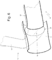
- the opening 20 passing through the side wall of the decorative tail pipe 11 is arranged in the area of the terminal end of the outlet pipe 10 of the silencer 9, as clearly shown in Figure 6 .
- each transmission conduit 13 By arranging the inlet 15 of each transmission conduit 13 in the area of the respective decorative tail pipe 11, the exhaust gases that enter each transmission conduit 13 (and go up to the insulating element 14) have a reduced pulsating pressure (almost ambient pressure) and a non-excessively high temperature; in this way, each transmission conduit 13 is subjected to relatively low thermal and mechanical stresses.
- each transmission conduit 13 could originate directly from the respective outlet pipe 10 instead of originating from the respective decorative tail pipe 11.
- the exhaust gases that enter each transmission conduit 13 (and go up to the insulating element 14) are hotter and at a higher pressure and thus subject each transmission conduit 13 to higher thermal and mechanical stresses.
- Each exhaust noise transmission device 12 serves the purpose of increasing (amplifying) the exhaust noise perceived inside the passenger compartment 5, so that the overall noise generated by the internal combustion engine 4 and perceived by the occupants of the car 1 is more "pleasant", i.e. more compliant with the desires/expectations of the occupants of the vehicle. Therefore, the presence of the exhaust noise transmission devices 12 makes it possible to remedy the penalization in the exhaust noise caused by the presence of turbines (in the case of turbocharged engines) and by the presence of the exhaust gas treatment devices 8 required by the new EUR06C regulations on pollutant emissions.
- the presence of the exhaust noise transmission devices 12 is particularly useful in the case of turbocharged engines since it allows for enhancing the exhaust noise otherwise attenuated by the turbine arranged along the exhaust pipe. Moreover, the presence of the devices 12 for the transmission of the intake noise is particularly useful in the case of turbo-compression since the presence of the compressor in the intake system further attenuates (compared to a similar naturally aspirated engine) the sound level generated by the internal combustion engine 4.
- the above-described car 1 provided with the exhaust noise transmission devices 12 has many advantages.
- the exhaust noise transmission devices 12 allow the exhaust noise from the internal combustion engine 4 to be better targeted towards the passenger compartment 5 (and thus enhanced) with a mode that is extremely pleasant (and therefore appreciated) to/by the occupants of the passenger compartment 5.
- This result is obtained thanks to the fact that the exhaust noise, however, follows the natural exit path and is " taken " when it comes out of the outlet pipes 10 of the silencers 9 and then (partially) transmitted towards the passenger compartment 5; in other words, the exhaust noise is not artificially "fired” towards the passenger compartment 5 through artificial transmission conduits, but, on the contrary, the exhaust noise reaches the passenger compartment 5 only by passing through the entire exhaust system 6, i.e. following the natural exit path of the exhaust noise.
- the exhaust noise transmission devices 12 are simple and economical to manufacture, since each one essentially consists of a tube (the transmission conduit 13), which is easy to assemble and to integrate into the car 1.
Landscapes
- Engineering & Computer Science (AREA)
- Chemical & Material Sciences (AREA)
- Combustion & Propulsion (AREA)
- Mechanical Engineering (AREA)
- General Engineering & Computer Science (AREA)
- Acoustics & Sound (AREA)
- Physics & Mathematics (AREA)
- Multimedia (AREA)
- Exhaust Silencers (AREA)
- Cooling, Air Intake And Gas Exhaust, And Fuel Tank Arrangements In Propulsion Units (AREA)
- Cleaning Of Streets, Tracks, Or Beaches (AREA)
- Tires In General (AREA)
- Road Paving Structures (AREA)
Description
- The present invention relates to a road vehicle with an internal combustion engine and provided with a device for the transmission of the exhaust noise.
- The present invention advantageously applies to a high-performance sports car, to which the present invention finds advantageous application without thereby losing generality.
- In a high-performance sports car the noise of the internal combustion engine that is perceived inside the passenger compartment is important.
- An important component in the judgment of a high-performance sports car is the "quality" of the sound emitted from the exhaust (not only and not so much in terms of intensity of the sound, but above all in terms of "pleasantness" of the sound itself), i.e. the degree of satisfaction in the use of a high-performance sports vehicle is also significantly affected by the "quality" of the sound emitted from the exhaust. In order to be able to effectively control the sound emitted from the exhaust, several high-performance sports cars have an exhaust system with a variable geometry, i.e. an exhaust system provided with one or more electrically or pneumatically controlled valves, which allow the path of the exhaust gases (and therefore of the sound) to be modified along the exhaust system; consequently, in use, the electronic control unit of the engine changes the geometry of the exhaust system in real time to always try to offer an exhaust sound corresponding to the expectations of the car users and of course compatibly with the achievement of the type-approval targets as for the exhaust noise level intensity.
- In general, turbocharged engines are penalised since the presence of the turbine along the exhaust pipe and of the compressor along the intake pipe add a filter and a lowering of the sound levels from both exhaust and intake.
- In addition, the latest EUR06C type-approval standards for pollutant emissions require the use of exhaust gas treatment devices that significantly affect the sound performance, since an anti-particulate filter (called GPF that stands for "Gasoline Particulate Filter") must be located in series to the catalyst, even in the case of petrol engines.
- To improve the perceived noise of the internal combustion engine inside the passenger compartment, devices for amplifying the intake noise have been proposed, for example as described in patent
US7975802B2 or in patentUS8127888B1 . A known device for the transmission of the intake noise comprises an amplification pipe originating in the intake pipe between the air filter and the inlet valve, and has an outlet opening which is free and points towards the passenger compartment; the amplification pipe houses a membrane, which serves the purpose of sealing the intake pipe with respect to the external environment and is carried by a bellows to be free to vibrate so as to generate sound waves under the thrust of the pressure waves present in the intake pipe. - To improve the perceived noise of the internal combustion engine inside the passenger compartment, devices for amplifying the exhaust noise have been proposed, for example as described in patent application
DE102012109668A1 or in patent applicationDE10042012A1 . A known device for the transmission of the exhaust noise comprises a transmission conduit, which originates in the area of a pipe of the exhaust system that releases into the atmosphere the gases generated by the combustion, ends in the area of the passenger compartment, and is provided, on the inside, with an insulating membrane that pneumatically seals the said transmission conduit. - The object of the present invention is to provide a road vehicle with an internal combustion engine and provided with a device for the transmission of the exhaust noise, which road vehicle is easy and inexpensive to manufacture and free from the drawbacks described above, i.e. allows for perceiving within the passenger compartment an exhaust noise which is natural and overall pleasant according to the expectations of the driver and any passengers.
- According to the present invention, a road vehicle with an internal combustion engine and provided with a device for the transmission of the exhaust noise is provided as claimed in the appended claims.
- The present invention will now be described with reference to the accompanying drawings, which illustrate a non-limiting embodiment thereof, in which:
-
Figure 1 is a schematic view of a car which is made in accordance with the present invention, has an internal combustion engine, and is provided with a device for the transmission of the exhaust noise; -
Figure 2 is a schematic and perspective view of a rear part of the car ofFigure 1 showing the device for the transmission of the exhaust noise; -
Figure 3 is a schematic and side view of a rear part of the car ofFigure 1 showing the device for the transmission of the exhaust noise; -
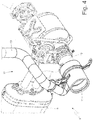
Figures 4 and5 are two perspective views of an end area of an exhaust pipe of the internal combustion engine ofFigure 1 ; and -
Figure 6 is a view in longitudinal section of the end area of the exhaust pipe ofFigures 4 and5 ; and -
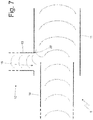
Figure 7 is a schematic view showing the sound wave paths in the end area of the exhaust pipe ofFigures 4 and5 . - In
Figure 1 , thenumeral 1 indicates, as a whole, a car equipped with twofront wheels 2 and tworear driving wheels 3, which receive the driving torque from a combustion heat engine 4 arranged in the front. Thecar 1 is provided with apassenger compartment 5 which is adapted to accommodate the driver and any passengers. - The internal combustion heat engine 4 has two rows of cylinders (not shown) arranged mutually angled to form a "V"; each row of cylinders comprises its own exhaust manifold, which collects the combustion-produced gases that cyclically flow out of the exhaust valves. An
exhaust system 6 is provided, which receives the gases produced by combustion from the two exhaust manifolds and releases them into the atmosphere. Theexhaust system 6 comprises two twin exhaust pipes 7 (i.e. symmetrical to each other), each of which is connected to a corresponding exhaust manifold (not shown), and ends at the tail of the car 1 (generally housed in the rear bumper). - Along each
exhaust pipe 7 there are several exhaustgas treatment devices 8 of the known type: there is always at least one catalyst and there could also be an anti-particulate filter (to meet the new EURO6C regulations on pollutant emissions, car manufacturers provide for the use of an anti-particulate filter - called GPF that stands for "Gasoline Particulate Filter" - even in the case of petrol engines). At the end of eachexhaust pipe 7 there is a silencer 9 provided with anoutlet pipe 10 constituting the end portion of theexhaust system 6. Eachoutlet pipe 10 is coupled to a decorative tubular (i.e. tube-shaped)tail pipe 11 only having an aesthetic function (i.e. masking theoutlet pipe 10 with a pleasant shape consistent with the layout of the car 1); in other words, eachdecorative tail pipe 11 is a tubular body (i.e., in the final analysis, a tube) which covers the end portion of thecorresponding outlet pipe 10 without touching (i.e. without any point of contact with) saidoutlet pipe 10. Thus, eachdecorative tail pipe 11 is a tubular body, which has a size (diameter) greater than thecorresponding outlet pipe 10, and partially covers theoutlet pipe 10 without touching (i.e. without any point of contact with) saidoutlet pipe 10. - As shown in
Figures 2 and3 , thecar 1 comprises a pair oftwin devices 12 for the transmission of the exhaust noise (preferably, but not necessarily, symmetrical to each other), each of which is coupled to acorresponding exhaust pipe 7 of theexhaust system 6, and in particular coupled to a corresponding outlet pipe 10 (physically coupled to thedecorative tail pipe 11 of the corresponding outlet pipe 10). Eachdevice 12 for the transmission of the exhaust noise comprises atransmission conduit 13, which originates close to theoutlet pipe 10 of the silencer 9, ends in the area of a wall of thepassenger compartment 5, and is provided, on the inside, with at least oneinsulating element 14, which is arranged inside thetransmission conduit 13 so as to tightly seal the saidtransmission conduit 13, allowing, at the same time, sound transmission (a plurality ofredundant insulating elements 14 can be provided in series to have a better seal guarantee). In other words, theinsulating element 14 is pneumatically insulating (i.e. it blocks the passage of gas by tight sealing) and is acoustically permeable (i.e. it allows the passage of sound). - In particular, the
transmission conduit 13 comprises aninlet 15, which is arranged close to theoutlet pipe 10 of the silencer 9, and anoutlet 16, which is opposite to theinlet 15, points towards thepassenger compartment 5, and faces a wall of the passenger compartment 5 (i.e. a panel delimiting the passenger compartment 5). In the case of an internal combustion engine 4 arranged in the front (as shown in the attached figures), theoutlet 16 of thetransmission conduit 13 is facing and close to a wall of the rear luggage compartment; in the case of an internal combustion engine 4 arranged in a central/rear position, theoutlet 16 of thetransmission conduit 13 is facing and close to the firewall (which is that part of the bodywork separating the engine compartment from thepassenger compartment 5 with the purpose of protecting thepassenger compartment 5 from heat, smells, and noise generated by the internal combustion engine 4). - The function of each
insulating element 14 is to prevent thetransmission conduit 13 from releasing the exhaust gases into thecar 1 and/or towards thepassenger compartment 5, and it performs this function by tight sealing saidtransmission conduit 13; in this way, the exhaust gases cannot in any way circulate along thetransmission conduit 13, the which exhaust gases stop at theinsulating element 14. It is important to emphasize that eachtransmission conduit 13 only has an acoustic function (i.e. it has no effect on the flow of the exhaust gases in the exhaust system 6) . - According to a possible, but non-limiting, embodiment, the
insulating element 14 comprises a flexible membrane (for example made of silicone), which locally seals thetransmission conduit 13 and is free to deform so as to prevent the passage of the exhaust gases and to allow, at the same time, transmission of the sound waves. According to an alternative embodiment, theinsulating element 14 comprises a rigid membrane (i.e. of a rigid plastic material) and an elastic ring element (which may be flat or cup-shaped) which is arranged around the rigid membrane and fixed to an inner wall of thetransmission conduit 13, so as to cause the rigid membrane to be suspended inside thetransmission conduit 13; in this manner, the membrane is suspended inside thetransmission conduit 13 and is free to oscillate under the thrust of the pressure pulsations. - According to a preferred, but non-limiting, embodiment illustrated in the attached figures, each
transmission conduit 13 comprises asound filtering device 17 of the low-pass type, which is arranged along thetransmission conduit 13 downstream of theinsulating element 14. According to a possible and non-limiting embodiment, thefiltering device 17 comprises a Helmholtz resonator. - According to a preferred, but non-limiting, embodiment illustrated in the attached figures, each
transmission conduit 13 comprises a furthersound filtering device 18 of the low-pass type, which is arranged along thetransmission conduit 13 downstream of the sound filtering device 17 (therefore downstream of the insulating element 14). According to a possible and non-limiting embodiment, thefiltering device 18 comprises a spongy body arranged along thetransmission conduit 13. - According to a possible, but non-limiting, embodiment, the
sound filtering devices 17 and 18 (in particular the sound filtering device 17) improve the quality and cleanliness of the sound by reducing the noise within a frequency range comprised between 1000 and 4000 Hz, which sound to the human ear as whistling, hissing or blowing. - According to a preferred, but non-limiting, embodiment illustrated in the attached figures, each
transmission conduit 13 comprises an adjustingvalve 19, which is arranged along thetransmission conduit 13 downstream of the sound filtering device 18 (therefore downstream of thesound filtering device 17 and downstream of the insulating element 14) and is designed to change the usable section for the passage through saidtransmission conduit 13. The adjustingvalve 19 is, for example, a throttle valve and is provided with an electrically operated actuator so as to be remotely controlled by an electronic control unit. The adjustingvalve 19 is movable between a closed position, in which it closes the passage (i.e. it deletes the usable passage section) through thetransmission conduit 13 by minimizing sound transmission along thetransmission conduit 13 and towards thepassenger compartment 5, and a fully open position, in which it maximizes the usable section for the passage through thetransmission conduit 13 by maximizing sound transmission along thetransmission conduit 13 and towards thepassenger compartment 5. The adjustingvalve 19 may take only two positions (i.e. the closed position and the fully open position) or it may also be capable of assuming intermediate positions between the closed position and the fully open position. - By way of example, each adjusting
valve 19 could be controlled according to the driving settings selected by the driver (for example, to increase the sound intensity perceived inside thepassenger compartment 5 when choosing a sporty driving and to reduce the sound intensity perceived inside thepassenger compartment 5 when choosing a comfortable ride). In addition, each adjustingvalve 19 could be controlled according to the number of revolutions of the internal combustion engine 4 to "reinforce" the sound intensity perceived inside thepassenger compartment 5 when needed. Each adjustingvalve 19 could also be controlled according to the position of the accelerator pedal to increase the sound intensity perceived inside thepassenger compartment 5 when the driver presses down on the accelerator pedal. - In the case in which there are several
insulating elements 14, thesound filtering devices valve 19 may be arranged downstream of all theinsulating elements 14 or may be interposed between the saidinsulating elements 14. - As illustrated in
Figures 4 ,5 and6 , eachdecorative tail pipe 11 is coupled to theoutlet pipe 10 of the silencer 9 and has, on the side (i.e. through the side wall), a through opening 20 from which thetransmission conduit 13 originates, i.e. at which theinlet 15 of thetransmission conduit 13 is located; in other words, thetransmission conduit 13 is integral with thedecorative tail pipe 11 and is connected (fixed) to thedecorative tail pipe 11 itself around the through opening (20). Eachoutlet pipe 10 of the silencer 9 is partially inserted inside thedecorative tail pipe 11 and does not touch saiddecorative tail pipe 11; in other words, eachdecorative tail pipe 11 is wider than theoutlet pipe 10 of the silencer 9 and houses, on the inside without mutual contact, one terminal end of saidoutlet pipe 10. The opening 20 passing through the side wall of thedecorative tail pipe 11 is arranged in the area of the terminal end of theoutlet pipe 10 of the silencer 9, as clearly shown inFigure 6 . - By arranging the
inlet 15 of eachtransmission conduit 13 in the area of the respectivedecorative tail pipe 11, the exhaust gases that enter each transmission conduit 13 (and go up to the insulating element 14) have a reduced pulsating pressure (almost ambient pressure) and a non-excessively high temperature; in this way, eachtransmission conduit 13 is subjected to relatively low thermal and mechanical stresses. - According to a different embodiment, not shown, each
transmission conduit 13 could originate directly from therespective outlet pipe 10 instead of originating from the respectivedecorative tail pipe 11. However, in this case, the exhaust gases that enter each transmission conduit 13 (and go up to the insulating element 14) are hotter and at a higher pressure and thus subject eachtransmission conduit 13 to higher thermal and mechanical stresses. - Each exhaust
noise transmission device 12 serves the purpose of increasing (amplifying) the exhaust noise perceived inside thepassenger compartment 5, so that the overall noise generated by the internal combustion engine 4 and perceived by the occupants of thecar 1 is more "pleasant", i.e. more compliant with the desires/expectations of the occupants of the vehicle. Therefore, the presence of the exhaustnoise transmission devices 12 makes it possible to remedy the penalization in the exhaust noise caused by the presence of turbines (in the case of turbocharged engines) and by the presence of the exhaustgas treatment devices 8 required by the new EUR06C regulations on pollutant emissions. - The presence of the exhaust
noise transmission devices 12 is particularly useful in the case of turbocharged engines since it allows for enhancing the exhaust noise otherwise attenuated by the turbine arranged along the exhaust pipe. Moreover, the presence of thedevices 12 for the transmission of the intake noise is particularly useful in the case of turbo-compression since the presence of the compressor in the intake system further attenuates (compared to a similar naturally aspirated engine) the sound level generated by the internal combustion engine 4. - The above-described
car 1 provided with the exhaustnoise transmission devices 12 has many advantages. - Firstly, the exhaust
noise transmission devices 12 allow the exhaust noise from the internal combustion engine 4 to be better targeted towards the passenger compartment 5 (and thus enhanced) with a mode that is extremely pleasant (and therefore appreciated) to/by the occupants of thepassenger compartment 5. This result is obtained thanks to the fact that the exhaust noise, however, follows the natural exit path and is "taken" when it comes out of theoutlet pipes 10 of the silencers 9 and then (partially) transmitted towards thepassenger compartment 5; in other words, the exhaust noise is not artificially "fired" towards thepassenger compartment 5 through artificial transmission conduits, but, on the contrary, the exhaust noise reaches thepassenger compartment 5 only by passing through theentire exhaust system 6, i.e. following the natural exit path of the exhaust noise. - In addition, the exhaust
noise transmission devices 12 are simple and economical to manufacture, since each one essentially consists of a tube (the transmission conduit 13), which is easy to assemble and to integrate into thecar 1.
Claims (10)
- A road vehicle (1) comprising:a passenger compartment (5);an internal combustion engine (4);an exhaust system (6), which releases into the atmosphere the gases generated by the combustion, is connected to the internal combustion engine (4), and ends with at least one silencer (9) provided with at least one outlet pipe (10), through which the gases generated by the combustion flow out of the exhaust system (6); andan exhaust noise transmission device (12), which is provided with a transmission conduit (13), which originates close to the outlet pipe (10) of the silencer (9), ends in the area of a wall of the passenger compartment (5), and is provided, on the inside, with at least one insulating element (14), which is pneumatically insulating, acoustically permeable, and arranged inside the transmission conduit (13) so as to pneumatically seal the transmission conduit (13);the road vehicle (1) is characterised in that:a decorative tubular tail pipe (11) coupled to the outlet pipe (10) of the silencer (9) is provided, so that the outlet pipe (10) of the silencer (9) is partially inserted inside the decorative tail pipe (11) and does not touch said decorative tail pipe (11), i.e. the decorative tail pipe (11) is wider than the outlet pipe (10) and houses, on the inside without mutual contact, one terminal end of said outlet pipe (10);the decorative tail pipe (11) has, on the side, a "c" from which the transmission conduit (13) originates; andthe opening (20) passing through the side wall of the decorative tail pipe (11) is arranged in the area of the terminal end of the outlet pipe (10) of the silencer (9).
- The road vehicle (1) according to claim 1, wherein the transmission conduit (13) is integral with the decorative tail pipe (11) and is connected to the decorative tail pipe (11) itself around the through opening (20).
- The road vehicle (1) according to claim 1 or 2, wherein the insulating element (14) comprises a flexible membrane, which locally seals the transmission conduit (13).
- The road vehicle (1) according to claim 1 or 2, wherein the insulating element (14) comprises:a rigid membrane; andan elastic element, which is arranged around the rigid membrane and is fixed to an inner wall of the transmission conduit (13), so as to cause the rigid membrane to be suspended inside the transmission conduit (13).
- The road vehicle (1) according to any of the claims from 1 to 4 and comprising a first sound filtering device (18) of the low-pass type, which is arranged along the transmission conduit (13) downstream of the insulating element (14).
- The road vehicle (1) according to claim 5, wherein the first filtering device (18) comprises a spongy body, which is arranged along the transmission conduit (13).
- The road vehicle (1) according to any of the claims from 1 to 6 and comprising a second sound filtering device (17) of the low-pass type, which is arranged along the transmission conduit (13) downstream of the insulating element (14).
- The road vehicle (1) according to claim 7, wherein the second filtering device (17) comprises a Helmholtz resonator.
- The road vehicle (1) according to any of the claims from 1 to 8 and comprising an adjusting valve (19), which is arranged along the transmission conduit (13) downstream of the insulating element (14) and is designed to change the usable section for the passage through the transmission conduit (13).
- The road vehicle (1) according to claim 9 and comprising at least one sound filtering device (17, 18) of the low-pass type, which is arranged along the transmission conduit (13) downstream of the insulating element (14) and upstream of the adjusting valve (19).
Applications Claiming Priority (1)
| Application Number | Priority Date | Filing Date | Title |
|---|---|---|---|
| ITUA2016A004078A ITUA20164078A1 (en) | 2016-06-03 | 2016-06-03 | ROAD VEHICLE WITH AN INTERNAL COMBUSTION ENGINE AND PROVIDED WITH A DISCHARGE NOISE TRANSMISSION DEVICE |
Publications (2)
| Publication Number | Publication Date |
|---|---|
| EP3252283A1 true EP3252283A1 (en) | 2017-12-06 |
| EP3252283B1 EP3252283B1 (en) | 2018-10-31 |
Family
ID=57045352
Family Applications (1)
| Application Number | Title | Priority Date | Filing Date |
|---|---|---|---|
| EP17174114.3A Active EP3252283B1 (en) | 2016-06-03 | 2017-06-01 | Road vehicle with an internal combustion engine and provided with a device for the transmission of the exhaust noise |
Country Status (3)
| Country | Link |
|---|---|
| US (1) | US10436085B2 (en) |
| EP (1) | EP3252283B1 (en) |
| IT (1) | ITUA20164078A1 (en) |
Families Citing this family (5)
| Publication number | Priority date | Publication date | Assignee | Title |
|---|---|---|---|---|
| IT201700044384A1 (en) * | 2017-04-21 | 2018-10-21 | Ferrari Spa | ROAD VEHICLE WITH AN INTERNAL COMBUSTION ENGINE AND PROVIDED WITH A DISCHARGE NOISE TRANSMISSION DEVICE |
| KR102378054B1 (en) * | 2017-08-25 | 2022-03-25 | 현대자동차주식회사 | Exhaust sound generating device of a vehicle |
| US10724410B1 (en) * | 2017-11-14 | 2020-07-28 | Brunswick Corporation | Exhaust sound enhancement assembly and method for a marine propulsion device |
| KR102768237B1 (en) * | 2020-07-14 | 2025-02-18 | 쩌지앙 길리 홀딩 그룹 씨오., 엘티디. | Exhaust noise devices, systems, vehicles and methods |
| IT202200019326A1 (en) * | 2022-09-21 | 2024-03-21 | Ferrari Spa | VEHICLE EQUIPPED WITH AN ELECTRIC DRIVE AXLE AND AN ACOUSTIC TRANSMISSION SYSTEM TO TRANSMIT SOUNDS INDICATING THE OPERATION OF THAT AXLE |
Citations (3)
| Publication number | Priority date | Publication date | Assignee | Title |
|---|---|---|---|---|
| DE10042012A1 (en) * | 1999-11-22 | 2001-05-23 | Daimler Chrysler Ag | Appliance for simulating sound characteristic of engine load in car interior uses vibrating membrane to convert exhaust gas pulsations into sound waves |
| US8127888B1 (en) * | 2011-02-02 | 2012-03-06 | Mann + Hummel, GmbH | Engine sound distribution apparatus for a motor vehicle |
| DE102012109668A1 (en) * | 2012-10-11 | 2014-04-17 | Dr. Ing. H.C. F. Porsche Aktiengesellschaft | Device for sound transmission in vehicle e.g. motor car, has transfer line that is provided with gastight membrane as sound transmission element to direct mouth region of exhaust system for connecting with inner space of motor car |
Family Cites Families (2)
| Publication number | Priority date | Publication date | Assignee | Title |
|---|---|---|---|---|
| US20070193251A1 (en) * | 2006-02-17 | 2007-08-23 | Eldridge Engineering Group (Div) - L. C. Eldridge Sales Co. Inc. | Eldridge ENJET - Engine Exhaust Jet Nozzle - An Exhaust Gas Dispersal and Dilution Method and Apparatus for Internal Combustion Engines |
| DE102010005067B4 (en) * | 2010-01-15 | 2022-10-20 | Dr. Ing. H.C. F. Porsche Aktiengesellschaft | Device for sound transmission |
-
2016
- 2016-06-03 IT ITUA2016A004078A patent/ITUA20164078A1/en unknown
-
2017
- 2017-06-01 US US15/610,956 patent/US10436085B2/en active Active
- 2017-06-01 EP EP17174114.3A patent/EP3252283B1/en active Active
Patent Citations (3)
| Publication number | Priority date | Publication date | Assignee | Title |
|---|---|---|---|---|
| DE10042012A1 (en) * | 1999-11-22 | 2001-05-23 | Daimler Chrysler Ag | Appliance for simulating sound characteristic of engine load in car interior uses vibrating membrane to convert exhaust gas pulsations into sound waves |
| US8127888B1 (en) * | 2011-02-02 | 2012-03-06 | Mann + Hummel, GmbH | Engine sound distribution apparatus for a motor vehicle |
| DE102012109668A1 (en) * | 2012-10-11 | 2014-04-17 | Dr. Ing. H.C. F. Porsche Aktiengesellschaft | Device for sound transmission in vehicle e.g. motor car, has transfer line that is provided with gastight membrane as sound transmission element to direct mouth region of exhaust system for connecting with inner space of motor car |
Also Published As
| Publication number | Publication date |
|---|---|
| US20170350287A1 (en) | 2017-12-07 |
| EP3252283B1 (en) | 2018-10-31 |
| ITUA20164078A1 (en) | 2017-12-03 |
| US10436085B2 (en) | 2019-10-08 |
Similar Documents
| Publication | Publication Date | Title |
|---|---|---|
| EP3392479B1 (en) | Road vehicle with an internal combustion engine and provided with an exhaust noise transmission device | |
| EP3252283B1 (en) | Road vehicle with an internal combustion engine and provided with a device for the transmission of the exhaust noise | |
| US6644436B2 (en) | Device for noise configuration in a motor vehicle | |
| US6755279B2 (en) | Controllable muffler system for internal combustion engine | |
| US9926896B2 (en) | Vehicular suction noise transmission system | |
| CN109072742A (en) | The exhaust apparatus of internal combustion engine | |
| RU2679062C2 (en) | Intake system silencer (options) | |
| US8302393B2 (en) | Exhaust system of an internal combustion engine | |
| CN106340289B (en) | Noise transmission system for a motor vehicle | |
| KR101762280B1 (en) | Structure of central-through type active control valve | |
| US20160273424A1 (en) | Mounting structure of variable valve for dual exhaust system | |
| EP3309383B1 (en) | Internal combustion engine provided with a device for the amplification of the intake sound | |
| US10738744B2 (en) | Vacuum actuated multi-frequency quarter-wave resonator for an internal combustion engine | |
| CN104389677A (en) | Noise reduction structure of supercharger | |
| US20050121254A1 (en) | Device for establishing noise in a motor vehicle | |
| WO2016082111A1 (en) | Noise reduction structure of supercharger | |
| JP6544368B2 (en) | Intake sound introduction device | |
| EP3392498B1 (en) | Pneumatically insulating and acoustically permeable symposer device for a noise transmission duct of an internal combustion engine | |
| JP2009144525A (en) | Engine exhaust gas purification device | |
| CN216043947U (en) | Muffler for vehicle exhaust system | |
| CN109555585A (en) | The method and apparatus reduced for realizing the encapsulated space in vehicle exhaust system | |
| CN211500767U (en) | Silencing exhaust pipe, vehicle silencing exhaust pipe control system and vehicle | |
| US20080011541A1 (en) | Internal combustion engine | |
| CN207437165U (en) | Exhaust silencer for internal combustion engine |
Legal Events
| Date | Code | Title | Description |
|---|---|---|---|
| PUAI | Public reference made under article 153(3) epc to a published international application that has entered the european phase |
Free format text: ORIGINAL CODE: 0009012 |
|
| STAA | Information on the status of an ep patent application or granted ep patent |
Free format text: STATUS: THE APPLICATION HAS BEEN PUBLISHED |
|
| AK | Designated contracting states |
Kind code of ref document: A1 Designated state(s): AL AT BE BG CH CY CZ DE DK EE ES FI FR GB GR HR HU IE IS IT LI LT LU LV MC MK MT NL NO PL PT RO RS SE SI SK SM TR |
|
| AX | Request for extension of the european patent |
Extension state: BA ME |
|
| STAA | Information on the status of an ep patent application or granted ep patent |
Free format text: STATUS: REQUEST FOR EXAMINATION WAS MADE |
|
| 17P | Request for examination filed |
Effective date: 20171204 |
|
| GRAP | Despatch of communication of intention to grant a patent |
Free format text: ORIGINAL CODE: EPIDOSNIGR1 |
|
| STAA | Information on the status of an ep patent application or granted ep patent |
Free format text: STATUS: GRANT OF PATENT IS INTENDED |
|
| INTG | Intention to grant announced |
Effective date: 20180507 |
|
| GRAS | Grant fee paid |
Free format text: ORIGINAL CODE: EPIDOSNIGR3 |
|
| GRAA | (expected) grant |
Free format text: ORIGINAL CODE: 0009210 |
|
| STAA | Information on the status of an ep patent application or granted ep patent |
Free format text: STATUS: THE PATENT HAS BEEN GRANTED |
|
| AK | Designated contracting states |
Kind code of ref document: B1 Designated state(s): AL AT BE BG CH CY CZ DE DK EE ES FI FR GB GR HR HU IE IS IT LI LT LU LV MC MK MT NL NO PL PT RO RS SE SI SK SM TR |
|
| REG | Reference to a national code |
Ref country code: CH Ref legal event code: EP Ref country code: GB Ref legal event code: FG4D |
|
| REG | Reference to a national code |
Ref country code: AT Ref legal event code: REF Ref document number: 1059683 Country of ref document: AT Kind code of ref document: T Effective date: 20181115 |
|
| REG | Reference to a national code |
Ref country code: DE Ref legal event code: R096 Ref document number: 602017000755 Country of ref document: DE |
|
| REG | Reference to a national code |
Ref country code: IE Ref legal event code: FG4D |
|
| REG | Reference to a national code |
Ref country code: NL Ref legal event code: MP Effective date: 20181031 |
|
| REG | Reference to a national code |
Ref country code: LT Ref legal event code: MG4D |
|
| REG | Reference to a national code |
Ref country code: AT Ref legal event code: MK05 Ref document number: 1059683 Country of ref document: AT Kind code of ref document: T Effective date: 20181031 |
|
| PG25 | Lapsed in a contracting state [announced via postgrant information from national office to epo] |
Ref country code: IS Free format text: LAPSE BECAUSE OF FAILURE TO SUBMIT A TRANSLATION OF THE DESCRIPTION OR TO PAY THE FEE WITHIN THE PRESCRIBED TIME-LIMIT Effective date: 20190228 Ref country code: AT Free format text: LAPSE BECAUSE OF FAILURE TO SUBMIT A TRANSLATION OF THE DESCRIPTION OR TO PAY THE FEE WITHIN THE PRESCRIBED TIME-LIMIT Effective date: 20181031 Ref country code: NO Free format text: LAPSE BECAUSE OF FAILURE TO SUBMIT A TRANSLATION OF THE DESCRIPTION OR TO PAY THE FEE WITHIN THE PRESCRIBED TIME-LIMIT Effective date: 20190131 Ref country code: LV Free format text: LAPSE BECAUSE OF FAILURE TO SUBMIT A TRANSLATION OF THE DESCRIPTION OR TO PAY THE FEE WITHIN THE PRESCRIBED TIME-LIMIT Effective date: 20181031 Ref country code: BG Free format text: LAPSE BECAUSE OF FAILURE TO SUBMIT A TRANSLATION OF THE DESCRIPTION OR TO PAY THE FEE WITHIN THE PRESCRIBED TIME-LIMIT Effective date: 20190131 Ref country code: LT Free format text: LAPSE BECAUSE OF FAILURE TO SUBMIT A TRANSLATION OF THE DESCRIPTION OR TO PAY THE FEE WITHIN THE PRESCRIBED TIME-LIMIT Effective date: 20181031 Ref country code: HR Free format text: LAPSE BECAUSE OF FAILURE TO SUBMIT A TRANSLATION OF THE DESCRIPTION OR TO PAY THE FEE WITHIN THE PRESCRIBED TIME-LIMIT Effective date: 20181031 Ref country code: ES Free format text: LAPSE BECAUSE OF FAILURE TO SUBMIT A TRANSLATION OF THE DESCRIPTION OR TO PAY THE FEE WITHIN THE PRESCRIBED TIME-LIMIT Effective date: 20181031 Ref country code: PL Free format text: LAPSE BECAUSE OF FAILURE TO SUBMIT A TRANSLATION OF THE DESCRIPTION OR TO PAY THE FEE WITHIN THE PRESCRIBED TIME-LIMIT Effective date: 20181031 Ref country code: FI Free format text: LAPSE BECAUSE OF FAILURE TO SUBMIT A TRANSLATION OF THE DESCRIPTION OR TO PAY THE FEE WITHIN THE PRESCRIBED TIME-LIMIT Effective date: 20181031 |
|
| PG25 | Lapsed in a contracting state [announced via postgrant information from national office to epo] |
Ref country code: PT Free format text: LAPSE BECAUSE OF FAILURE TO SUBMIT A TRANSLATION OF THE DESCRIPTION OR TO PAY THE FEE WITHIN THE PRESCRIBED TIME-LIMIT Effective date: 20190301 Ref country code: GR Free format text: LAPSE BECAUSE OF FAILURE TO SUBMIT A TRANSLATION OF THE DESCRIPTION OR TO PAY THE FEE WITHIN THE PRESCRIBED TIME-LIMIT Effective date: 20190201 Ref country code: SE Free format text: LAPSE BECAUSE OF FAILURE TO SUBMIT A TRANSLATION OF THE DESCRIPTION OR TO PAY THE FEE WITHIN THE PRESCRIBED TIME-LIMIT Effective date: 20181031 Ref country code: RS Free format text: LAPSE BECAUSE OF FAILURE TO SUBMIT A TRANSLATION OF THE DESCRIPTION OR TO PAY THE FEE WITHIN THE PRESCRIBED TIME-LIMIT Effective date: 20181031 Ref country code: AL Free format text: LAPSE BECAUSE OF FAILURE TO SUBMIT A TRANSLATION OF THE DESCRIPTION OR TO PAY THE FEE WITHIN THE PRESCRIBED TIME-LIMIT Effective date: 20181031 Ref country code: NL Free format text: LAPSE BECAUSE OF FAILURE TO SUBMIT A TRANSLATION OF THE DESCRIPTION OR TO PAY THE FEE WITHIN THE PRESCRIBED TIME-LIMIT Effective date: 20181031 |
|
| PG25 | Lapsed in a contracting state [announced via postgrant information from national office to epo] |
Ref country code: DK Free format text: LAPSE BECAUSE OF FAILURE TO SUBMIT A TRANSLATION OF THE DESCRIPTION OR TO PAY THE FEE WITHIN THE PRESCRIBED TIME-LIMIT Effective date: 20181031 Ref country code: CZ Free format text: LAPSE BECAUSE OF FAILURE TO SUBMIT A TRANSLATION OF THE DESCRIPTION OR TO PAY THE FEE WITHIN THE PRESCRIBED TIME-LIMIT Effective date: 20181031 |
|
| REG | Reference to a national code |
Ref country code: DE Ref legal event code: R097 Ref document number: 602017000755 Country of ref document: DE |
|
| PG25 | Lapsed in a contracting state [announced via postgrant information from national office to epo] |
Ref country code: SK Free format text: LAPSE BECAUSE OF FAILURE TO SUBMIT A TRANSLATION OF THE DESCRIPTION OR TO PAY THE FEE WITHIN THE PRESCRIBED TIME-LIMIT Effective date: 20181031 Ref country code: RO Free format text: LAPSE BECAUSE OF FAILURE TO SUBMIT A TRANSLATION OF THE DESCRIPTION OR TO PAY THE FEE WITHIN THE PRESCRIBED TIME-LIMIT Effective date: 20181031 Ref country code: EE Free format text: LAPSE BECAUSE OF FAILURE TO SUBMIT A TRANSLATION OF THE DESCRIPTION OR TO PAY THE FEE WITHIN THE PRESCRIBED TIME-LIMIT Effective date: 20181031 Ref country code: SM Free format text: LAPSE BECAUSE OF FAILURE TO SUBMIT A TRANSLATION OF THE DESCRIPTION OR TO PAY THE FEE WITHIN THE PRESCRIBED TIME-LIMIT Effective date: 20181031 |
|
| PLBE | No opposition filed within time limit |
Free format text: ORIGINAL CODE: 0009261 |
|
| STAA | Information on the status of an ep patent application or granted ep patent |
Free format text: STATUS: NO OPPOSITION FILED WITHIN TIME LIMIT |
|
| 26N | No opposition filed |
Effective date: 20190801 |
|
| PG25 | Lapsed in a contracting state [announced via postgrant information from national office to epo] |
Ref country code: SI Free format text: LAPSE BECAUSE OF FAILURE TO SUBMIT A TRANSLATION OF THE DESCRIPTION OR TO PAY THE FEE WITHIN THE PRESCRIBED TIME-LIMIT Effective date: 20181031 |
|
| PG25 | Lapsed in a contracting state [announced via postgrant information from national office to epo] |
Ref country code: MC Free format text: LAPSE BECAUSE OF FAILURE TO SUBMIT A TRANSLATION OF THE DESCRIPTION OR TO PAY THE FEE WITHIN THE PRESCRIBED TIME-LIMIT Effective date: 20181031 |
|
| REG | Reference to a national code |
Ref country code: BE Ref legal event code: MM Effective date: 20190630 |
|
| PG25 | Lapsed in a contracting state [announced via postgrant information from national office to epo] |
Ref country code: TR Free format text: LAPSE BECAUSE OF FAILURE TO SUBMIT A TRANSLATION OF THE DESCRIPTION OR TO PAY THE FEE WITHIN THE PRESCRIBED TIME-LIMIT Effective date: 20181031 |
|
| PG25 | Lapsed in a contracting state [announced via postgrant information from national office to epo] |
Ref country code: IE Free format text: LAPSE BECAUSE OF NON-PAYMENT OF DUE FEES Effective date: 20190601 |
|
| PG25 | Lapsed in a contracting state [announced via postgrant information from national office to epo] |
Ref country code: LU Free format text: LAPSE BECAUSE OF NON-PAYMENT OF DUE FEES Effective date: 20190601 Ref country code: BE Free format text: LAPSE BECAUSE OF NON-PAYMENT OF DUE FEES Effective date: 20190630 |
|
| PG25 | Lapsed in a contracting state [announced via postgrant information from national office to epo] |
Ref country code: FR Free format text: LAPSE BECAUSE OF NON-PAYMENT OF DUE FEES Effective date: 20190630 |
|
| REG | Reference to a national code |
Ref country code: CH Ref legal event code: PL |
|
| PG25 | Lapsed in a contracting state [announced via postgrant information from national office to epo] |
Ref country code: CH Free format text: LAPSE BECAUSE OF NON-PAYMENT OF DUE FEES Effective date: 20200630 Ref country code: LI Free format text: LAPSE BECAUSE OF NON-PAYMENT OF DUE FEES Effective date: 20200630 |
|
| PG25 | Lapsed in a contracting state [announced via postgrant information from national office to epo] |
Ref country code: CY Free format text: LAPSE BECAUSE OF FAILURE TO SUBMIT A TRANSLATION OF THE DESCRIPTION OR TO PAY THE FEE WITHIN THE PRESCRIBED TIME-LIMIT Effective date: 20181031 |
|
| PG25 | Lapsed in a contracting state [announced via postgrant information from national office to epo] |
Ref country code: HU Free format text: LAPSE BECAUSE OF FAILURE TO SUBMIT A TRANSLATION OF THE DESCRIPTION OR TO PAY THE FEE WITHIN THE PRESCRIBED TIME-LIMIT; INVALID AB INITIO Effective date: 20170601 Ref country code: MT Free format text: LAPSE BECAUSE OF FAILURE TO SUBMIT A TRANSLATION OF THE DESCRIPTION OR TO PAY THE FEE WITHIN THE PRESCRIBED TIME-LIMIT Effective date: 20181031 |
|
| PG25 | Lapsed in a contracting state [announced via postgrant information from national office to epo] |
Ref country code: MK Free format text: LAPSE BECAUSE OF FAILURE TO SUBMIT A TRANSLATION OF THE DESCRIPTION OR TO PAY THE FEE WITHIN THE PRESCRIBED TIME-LIMIT Effective date: 20181031 |
|
| P01 | Opt-out of the competence of the unified patent court (upc) registered |
Effective date: 20230525 |
|
| PGFP | Annual fee paid to national office [announced via postgrant information from national office to epo] |
Ref country code: DE Payment date: 20250626 Year of fee payment: 9 |
|
| PGFP | Annual fee paid to national office [announced via postgrant information from national office to epo] |
Ref country code: GB Payment date: 20250617 Year of fee payment: 9 |
|
| PGFP | Annual fee paid to national office [announced via postgrant information from national office to epo] |
Ref country code: IT Payment date: 20250611 Year of fee payment: 9 |