EP3252185A1 - Film forming device and method for manufacturing coated cutting tool - Google Patents
Film forming device and method for manufacturing coated cutting tool Download PDFInfo
- Publication number
- EP3252185A1 EP3252185A1 EP15880017.7A EP15880017A EP3252185A1 EP 3252185 A1 EP3252185 A1 EP 3252185A1 EP 15880017 A EP15880017 A EP 15880017A EP 3252185 A1 EP3252185 A1 EP 3252185A1
- Authority
- EP
- European Patent Office
- Prior art keywords
- carrier
- deposition
- region
- conveyed
- coated
- Prior art date
- Legal status (The legal status is an assumption and is not a legal conclusion. Google has not performed a legal analysis and makes no representation as to the accuracy of the status listed.)
- Granted
Links
Images




Classifications
-
- C—CHEMISTRY; METALLURGY
- C23—COATING METALLIC MATERIAL; COATING MATERIAL WITH METALLIC MATERIAL; CHEMICAL SURFACE TREATMENT; DIFFUSION TREATMENT OF METALLIC MATERIAL; COATING BY VACUUM EVAPORATION, BY SPUTTERING, BY ION IMPLANTATION OR BY CHEMICAL VAPOUR DEPOSITION, IN GENERAL; INHIBITING CORROSION OF METALLIC MATERIAL OR INCRUSTATION IN GENERAL
- C23C—COATING METALLIC MATERIAL; COATING MATERIAL WITH METALLIC MATERIAL; SURFACE TREATMENT OF METALLIC MATERIAL BY DIFFUSION INTO THE SURFACE, BY CHEMICAL CONVERSION OR SUBSTITUTION; COATING BY VACUUM EVAPORATION, BY SPUTTERING, BY ION IMPLANTATION OR BY CHEMICAL VAPOUR DEPOSITION, IN GENERAL
- C23C14/00—Coating by vacuum evaporation, by sputtering or by ion implantation of the coating forming material
- C23C14/22—Coating by vacuum evaporation, by sputtering or by ion implantation of the coating forming material characterised by the process of coating
- C23C14/24—Vacuum evaporation
- C23C14/32—Vacuum evaporation by explosion; by evaporation and subsequent ionisation of the vapours, e.g. ion-plating
- C23C14/325—Electric arc evaporation
-
- C—CHEMISTRY; METALLURGY
- C23—COATING METALLIC MATERIAL; COATING MATERIAL WITH METALLIC MATERIAL; CHEMICAL SURFACE TREATMENT; DIFFUSION TREATMENT OF METALLIC MATERIAL; COATING BY VACUUM EVAPORATION, BY SPUTTERING, BY ION IMPLANTATION OR BY CHEMICAL VAPOUR DEPOSITION, IN GENERAL; INHIBITING CORROSION OF METALLIC MATERIAL OR INCRUSTATION IN GENERAL
- C23C—COATING METALLIC MATERIAL; COATING MATERIAL WITH METALLIC MATERIAL; SURFACE TREATMENT OF METALLIC MATERIAL BY DIFFUSION INTO THE SURFACE, BY CHEMICAL CONVERSION OR SUBSTITUTION; COATING BY VACUUM EVAPORATION, BY SPUTTERING, BY ION IMPLANTATION OR BY CHEMICAL VAPOUR DEPOSITION, IN GENERAL
- C23C14/00—Coating by vacuum evaporation, by sputtering or by ion implantation of the coating forming material
- C23C14/22—Coating by vacuum evaporation, by sputtering or by ion implantation of the coating forming material characterised by the process of coating
- C23C14/34—Sputtering
- C23C14/3435—Applying energy to the substrate during sputtering
- C23C14/345—Applying energy to the substrate during sputtering using substrate bias
-
- B—PERFORMING OPERATIONS; TRANSPORTING
- B23—MACHINE TOOLS; METAL-WORKING NOT OTHERWISE PROVIDED FOR
- B23B—TURNING; BORING
- B23B27/00—Tools for turning or boring machines; Tools of a similar kind in general; Accessories therefor
- B23B27/14—Cutting tools of which the bits or tips or cutting inserts are of special material
-
- B—PERFORMING OPERATIONS; TRANSPORTING
- B23—MACHINE TOOLS; METAL-WORKING NOT OTHERWISE PROVIDED FOR
- B23C—MILLING
- B23C5/00—Milling-cutters
- B23C5/16—Milling-cutters characterised by physical features other than shape
- B23C5/20—Milling-cutters characterised by physical features other than shape with removable cutter bits or teeth or cutting inserts
- B23C5/202—Plate-like cutting inserts with special form
-
- B—PERFORMING OPERATIONS; TRANSPORTING
- B23—MACHINE TOOLS; METAL-WORKING NOT OTHERWISE PROVIDED FOR
- B23P—METAL-WORKING NOT OTHERWISE PROVIDED FOR; COMBINED OPERATIONS; UNIVERSAL MACHINE TOOLS
- B23P15/00—Making specific metal objects by operations not covered by a single other subclass or a group in this subclass
- B23P15/28—Making specific metal objects by operations not covered by a single other subclass or a group in this subclass cutting tools
-
- C—CHEMISTRY; METALLURGY
- C23—COATING METALLIC MATERIAL; COATING MATERIAL WITH METALLIC MATERIAL; CHEMICAL SURFACE TREATMENT; DIFFUSION TREATMENT OF METALLIC MATERIAL; COATING BY VACUUM EVAPORATION, BY SPUTTERING, BY ION IMPLANTATION OR BY CHEMICAL VAPOUR DEPOSITION, IN GENERAL; INHIBITING CORROSION OF METALLIC MATERIAL OR INCRUSTATION IN GENERAL
- C23C—COATING METALLIC MATERIAL; COATING MATERIAL WITH METALLIC MATERIAL; SURFACE TREATMENT OF METALLIC MATERIAL BY DIFFUSION INTO THE SURFACE, BY CHEMICAL CONVERSION OR SUBSTITUTION; COATING BY VACUUM EVAPORATION, BY SPUTTERING, BY ION IMPLANTATION OR BY CHEMICAL VAPOUR DEPOSITION, IN GENERAL
- C23C14/00—Coating by vacuum evaporation, by sputtering or by ion implantation of the coating forming material
- C23C14/22—Coating by vacuum evaporation, by sputtering or by ion implantation of the coating forming material characterised by the process of coating
- C23C14/24—Vacuum evaporation
- C23C14/32—Vacuum evaporation by explosion; by evaporation and subsequent ionisation of the vapours, e.g. ion-plating
-
- C—CHEMISTRY; METALLURGY
- C23—COATING METALLIC MATERIAL; COATING MATERIAL WITH METALLIC MATERIAL; CHEMICAL SURFACE TREATMENT; DIFFUSION TREATMENT OF METALLIC MATERIAL; COATING BY VACUUM EVAPORATION, BY SPUTTERING, BY ION IMPLANTATION OR BY CHEMICAL VAPOUR DEPOSITION, IN GENERAL; INHIBITING CORROSION OF METALLIC MATERIAL OR INCRUSTATION IN GENERAL
- C23C—COATING METALLIC MATERIAL; COATING MATERIAL WITH METALLIC MATERIAL; SURFACE TREATMENT OF METALLIC MATERIAL BY DIFFUSION INTO THE SURFACE, BY CHEMICAL CONVERSION OR SUBSTITUTION; COATING BY VACUUM EVAPORATION, BY SPUTTERING, BY ION IMPLANTATION OR BY CHEMICAL VAPOUR DEPOSITION, IN GENERAL
- C23C14/00—Coating by vacuum evaporation, by sputtering or by ion implantation of the coating forming material
- C23C14/22—Coating by vacuum evaporation, by sputtering or by ion implantation of the coating forming material characterised by the process of coating
- C23C14/50—Substrate holders
-
- C—CHEMISTRY; METALLURGY
- C23—COATING METALLIC MATERIAL; COATING MATERIAL WITH METALLIC MATERIAL; CHEMICAL SURFACE TREATMENT; DIFFUSION TREATMENT OF METALLIC MATERIAL; COATING BY VACUUM EVAPORATION, BY SPUTTERING, BY ION IMPLANTATION OR BY CHEMICAL VAPOUR DEPOSITION, IN GENERAL; INHIBITING CORROSION OF METALLIC MATERIAL OR INCRUSTATION IN GENERAL
- C23C—COATING METALLIC MATERIAL; COATING MATERIAL WITH METALLIC MATERIAL; SURFACE TREATMENT OF METALLIC MATERIAL BY DIFFUSION INTO THE SURFACE, BY CHEMICAL CONVERSION OR SUBSTITUTION; COATING BY VACUUM EVAPORATION, BY SPUTTERING, BY ION IMPLANTATION OR BY CHEMICAL VAPOUR DEPOSITION, IN GENERAL
- C23C14/00—Coating by vacuum evaporation, by sputtering or by ion implantation of the coating forming material
- C23C14/22—Coating by vacuum evaporation, by sputtering or by ion implantation of the coating forming material characterised by the process of coating
- C23C14/50—Substrate holders
- C23C14/505—Substrate holders for rotation of the substrates
-
- C—CHEMISTRY; METALLURGY
- C23—COATING METALLIC MATERIAL; COATING MATERIAL WITH METALLIC MATERIAL; CHEMICAL SURFACE TREATMENT; DIFFUSION TREATMENT OF METALLIC MATERIAL; COATING BY VACUUM EVAPORATION, BY SPUTTERING, BY ION IMPLANTATION OR BY CHEMICAL VAPOUR DEPOSITION, IN GENERAL; INHIBITING CORROSION OF METALLIC MATERIAL OR INCRUSTATION IN GENERAL
- C23C—COATING METALLIC MATERIAL; COATING MATERIAL WITH METALLIC MATERIAL; SURFACE TREATMENT OF METALLIC MATERIAL BY DIFFUSION INTO THE SURFACE, BY CHEMICAL CONVERSION OR SUBSTITUTION; COATING BY VACUUM EVAPORATION, BY SPUTTERING, BY ION IMPLANTATION OR BY CHEMICAL VAPOUR DEPOSITION, IN GENERAL
- C23C14/00—Coating by vacuum evaporation, by sputtering or by ion implantation of the coating forming material
- C23C14/22—Coating by vacuum evaporation, by sputtering or by ion implantation of the coating forming material characterised by the process of coating
- C23C14/56—Apparatus specially adapted for continuous coating; Arrangements for maintaining the vacuum, e.g. vacuum locks
- C23C14/568—Transferring the substrates through a series of coating stations
-
- C—CHEMISTRY; METALLURGY
- C23—COATING METALLIC MATERIAL; COATING MATERIAL WITH METALLIC MATERIAL; CHEMICAL SURFACE TREATMENT; DIFFUSION TREATMENT OF METALLIC MATERIAL; COATING BY VACUUM EVAPORATION, BY SPUTTERING, BY ION IMPLANTATION OR BY CHEMICAL VAPOUR DEPOSITION, IN GENERAL; INHIBITING CORROSION OF METALLIC MATERIAL OR INCRUSTATION IN GENERAL
- C23C—COATING METALLIC MATERIAL; COATING MATERIAL WITH METALLIC MATERIAL; SURFACE TREATMENT OF METALLIC MATERIAL BY DIFFUSION INTO THE SURFACE, BY CHEMICAL CONVERSION OR SUBSTITUTION; COATING BY VACUUM EVAPORATION, BY SPUTTERING, BY ION IMPLANTATION OR BY CHEMICAL VAPOUR DEPOSITION, IN GENERAL
- C23C16/00—Chemical coating by decomposition of gaseous compounds, without leaving reaction products of surface material in the coating, i.e. chemical vapour deposition [CVD] processes
- C23C16/44—Chemical coating by decomposition of gaseous compounds, without leaving reaction products of surface material in the coating, i.e. chemical vapour deposition [CVD] processes characterised by the method of coating
- C23C16/458—Chemical coating by decomposition of gaseous compounds, without leaving reaction products of surface material in the coating, i.e. chemical vapour deposition [CVD] processes characterised by the method of coating characterised by the method used for supporting substrates in the reaction chamber
- C23C16/4582—Rigid and flat substrates, e.g. plates or discs
- C23C16/4587—Rigid and flat substrates, e.g. plates or discs the substrate being supported substantially vertically
- C23C16/4588—Rigid and flat substrates, e.g. plates or discs the substrate being supported substantially vertically the substrate being rotated
-
- C—CHEMISTRY; METALLURGY
- C23—COATING METALLIC MATERIAL; COATING MATERIAL WITH METALLIC MATERIAL; CHEMICAL SURFACE TREATMENT; DIFFUSION TREATMENT OF METALLIC MATERIAL; COATING BY VACUUM EVAPORATION, BY SPUTTERING, BY ION IMPLANTATION OR BY CHEMICAL VAPOUR DEPOSITION, IN GENERAL; INHIBITING CORROSION OF METALLIC MATERIAL OR INCRUSTATION IN GENERAL
- C23C—COATING METALLIC MATERIAL; COATING MATERIAL WITH METALLIC MATERIAL; SURFACE TREATMENT OF METALLIC MATERIAL BY DIFFUSION INTO THE SURFACE, BY CHEMICAL CONVERSION OR SUBSTITUTION; COATING BY VACUUM EVAPORATION, BY SPUTTERING, BY ION IMPLANTATION OR BY CHEMICAL VAPOUR DEPOSITION, IN GENERAL
- C23C16/00—Chemical coating by decomposition of gaseous compounds, without leaving reaction products of surface material in the coating, i.e. chemical vapour deposition [CVD] processes
- C23C16/44—Chemical coating by decomposition of gaseous compounds, without leaving reaction products of surface material in the coating, i.e. chemical vapour deposition [CVD] processes characterised by the method of coating
- C23C16/54—Apparatus specially adapted for continuous coating
-
- B—PERFORMING OPERATIONS; TRANSPORTING
- B23—MACHINE TOOLS; METAL-WORKING NOT OTHERWISE PROVIDED FOR
- B23B—TURNING; BORING
- B23B2228/00—Properties of materials of tools or workpieces, materials of tools or workpieces applied in a specific manner
- B23B2228/10—Coatings
-
- B—PERFORMING OPERATIONS; TRANSPORTING
- B23—MACHINE TOOLS; METAL-WORKING NOT OTHERWISE PROVIDED FOR
- B23C—MILLING
- B23C2200/00—Details of milling cutting inserts
- B23C2200/36—Other features of the milling insert not covered by B23C2200/04 - B23C2200/32
-
- C—CHEMISTRY; METALLURGY
- C23—COATING METALLIC MATERIAL; COATING MATERIAL WITH METALLIC MATERIAL; CHEMICAL SURFACE TREATMENT; DIFFUSION TREATMENT OF METALLIC MATERIAL; COATING BY VACUUM EVAPORATION, BY SPUTTERING, BY ION IMPLANTATION OR BY CHEMICAL VAPOUR DEPOSITION, IN GENERAL; INHIBITING CORROSION OF METALLIC MATERIAL OR INCRUSTATION IN GENERAL
- C23C—COATING METALLIC MATERIAL; COATING MATERIAL WITH METALLIC MATERIAL; SURFACE TREATMENT OF METALLIC MATERIAL BY DIFFUSION INTO THE SURFACE, BY CHEMICAL CONVERSION OR SUBSTITUTION; COATING BY VACUUM EVAPORATION, BY SPUTTERING, BY ION IMPLANTATION OR BY CHEMICAL VAPOUR DEPOSITION, IN GENERAL
- C23C14/00—Coating by vacuum evaporation, by sputtering or by ion implantation of the coating forming material
- C23C14/22—Coating by vacuum evaporation, by sputtering or by ion implantation of the coating forming material characterised by the process of coating
- C23C14/54—Controlling or regulating the coating process
- C23C14/541—Heating or cooling of the substrates
Definitions
- the present invention relates to a deposition apparatus and a method for manufacturing a coated cutting tool.
- a deposition apparatus which applies coating to a surface of a cutting tool while rotating the cutting tool (for example, refer to PTL 1).
- an interference member is provided in the vicinity of a path of a carrier frame while a gear-shaped rotating wheel is provided on a table shaft supporting a workpiece. The interference member and the rotating wheel come into contact with each other according to the movement of the carrier frame, and the workpiece is rotated by the rotation of the rotating wheel.
- An object of the present invention is to provide a deposition apparatus capable of forming a coating film having a high quality by stably holding a bias voltage when coating is performed while a workpiece is rotated.
- Another object of the present invention is to provide a method for manufacturing a cutting tool including a coating film having a high quality.
- a deposition apparatus including: a deposition chamber which includes a deposition region for forming a coating film on an object to be coated; a conveying device which conveys a conveyed carrier supporting the object to be coated; and a bias power source which applies a bias voltage to the object to be coated via the conveyed carrier, in which the coating film is formed by allowing the conveyed carrier to pass through the deposition region while applying a bias voltage to the object to be coated, a plurality of rods which support the object to be coated and rotate around axes are disposed in the conveyed carrier along a carrier conveying direction in an upright posture, a protrusion member protruding to the outside in a radial direction is provided on an outer peripheral surface of the rod, an interference member which catches the protrusion member of the conveyed carrier moving in the deposition chamber and rotates the rod around the axis is provided on a wall surface of the deposition chamber via an insulation member, and the interference member and the
- the interference member and the protrusion member of the conveyed carrier can be maintained at the same potential, it is possible to prevent a voltage of the conveyed carrier from decreasing due to spark generated when the interference member and the protrusion member come into contact with each other. Therefore, it is possible to form a coating film having a high quality.
- the conveying device may include a plurality of conveying rollers disposed along a conveying direction of the conveyed carrier, and the interference member and the bias power source may be electrically connected to each other via one conveying roller or the plurality of conveying rollers.
- the interference member may be provided at a position where the interference member rotates the rod passing through the deposition region.
- the interference member may rotate the rod at a center portion of the deposition region in the carrier conveying direction.
- a plurality of protrusion members may be provided at equal intervals in circumferential directions of the rods.
- the deposition chamber may include a heating region which is disposed to be adjacent to the deposition region in the carrier conveying direction and heats the object to be coated before the object to be coated enters the deposition region, and a carrier-waiting region which accommodates the conveyed carrier between the deposition region and an end portion of the deposition chamber.
- the heating regions may be provided on both sides of the deposition region in the carrier conveying direction.
- a method for manufacturing a coated cutting tool using a deposition apparatus including a deposition chamber which forms a coating film on an object to be coated, a conveying device which conveys a conveyed carrier supporting the object to be coated, and a bias power source which applies a bias voltage to the object to be coated via the conveyed carrier, in which a plurality of rods which support the object to be coated and rotate around axes are disposed in the conveyed carrier along a carrier conveying direction in an upright posture, a protrusion member protruding to the outside in a radial direction is provided on an outer peripheral surface of the rod, and an interference member which catches the protrusion member and rotates the rod around the axis is provided on a wall surface of the deposition chamber, the method including: a process of mounting the cutting tool on the conveyed carrier; a process of conveying the conveyed carrier into the deposition chamber and allowing the conveyed carrier to pass through the deposition region; and
- the interference member and the protrusion member of the conveyed carrier can be maintained at the same potential, it is possible to prevent a voltage of the conveyed carrier from decreasing due to spark generated when the interference member and the protrusion member come into contact with each other. Therefore, it is possible to manufacture a cutting tool including a coating film having a high quality.
- the rod may be rotated while passing through the deposition region.
- the rod may be rotated at the center portion of the deposition region in the carrier conveying direction.
- the conveyed carrier may be conveyed into the deposition chamber and may be sequentially passed through a heating region heating the cutting tool and the deposition region.
- the heating region may be disposed on both sides in a conveying direction of the conveyed carrier with respect to the deposition region, and a plurality of layers of coating films may be formed on the cutting tool by reciprocating the conveyed carrier with respect to a region including a plurality of heating regions and deposition regions.
- the present invention it is possible to stably apply a bias voltage to a workpiece, and the deposition apparatus which can form a coating film having a high quality is provided.
- the method for manufacturing the cutting tool including the coating film having a high quality is provided.
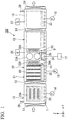
- FIG. 1 is a side view showing an internal structure of a deposition apparatus according to an embodiment.
- FIG. 2 is a top view showing the internal structure of the deposition apparatus according to the embodiment.
- FIG. 3 is a side view showing a structure of a conveyed carrier.
- a deposition apparatus 100 of the present embodiment shown in FIGS. 1 and 2 is an in-line deposition apparatus which performs film forming processing on a cutting tool W while conveying a conveyed carrier 80 on which the cutting tool W are mounted.
- the conveyed carrier 80 includes a rectangular frame 81 and a plurality of (five in the shown example) rods 82 which are disposed inside the frame 81 in an upright posture.
- Cutting tools W which are objects to which a coating film (a coating film for a cutting tool) is to be formed are inserted into each rod 82 so as to be supported.
- FIG. 4 is a view showing a support aspect of the cutting tools W.
- the plurality of cutting tools W are disposed in the rod 82 in a state where cylindrical spacers S are interposed between the cutting tools W adjacent to each other.
- the rod 82 is rotatable around the axis.
- a rotation mechanism 84 for rotating the rod 82 is provided on the lower portion of the rod 82.
- the rotation mechanism 84 includes a cylindrical support portion 85 which is fixed to the rod 82, and six protrusion members 86 which are provided on an outer peripheral surface of the support portion 85 at equal intervals in a circumferential direction. All of the protrusion members 86 extend from the support portion 85 in the radial direction of the rod 82 and are orthogonal to the rod 82. Accordingly, in the present embodiment, it is possible to rotate the cutting tools W at a pitch of approximately 60°.
- the number or the disposition angle of the protrusion members 86 can be appropriately changed according to the rotation aspects of the cutting tools W.
- the installation number of the protrusion members 86 may be four or eight, and the plurality of protrusion members 86 may be disposed at irregular intervals in the circumferential direction of the rod 82.
- the cutting tool W is a cutting insert which is used in a cutting edge-replaceable cutting tool.
- the cutting insert is a polygonal plate-shaped member which is formed of a hard material such as cemented carbide and a circular attachment hole for attaching the cutting insert to a cutting tool body is formed in the cutting insert.
- the rod 82 is inserted into attachment holes h of the cutting tools W.
- the deposition apparatus 100 includes a pre-treatment chamber 11, a deposition chamber 12, and a post-treatment chamber 13.
- the pre-treatment chamber 11 and the deposition chamber 12 connected to each other via a vacuum valve 52, and the deposition chamber 12 and the post-treatment chamber 13 are connected to each other via a vacuum valve 53.
- An entrance-side gate valve 51 for introducing the conveyed carrier 80 into the deposition apparatus 100 is provided in the pre-treatment chamber 11.
- An outlet side gate valve 54 for discharging the conveyed carrier 80 is provided in the post-treatment chamber 13.
- Roller conveyors (conveying devices) 31 to 33 in which a plurality of conveying rollers are juxtaposed are laid on the bottom portion sides of the pre-treatment chamber 11, the deposition chamber 12, and the post-treatment chamber 13.
- the conveyed carrier 80 is conveyed on the roller conveyors 31 to 33.
- a path of the conveyed carrier 80 on the roller conveyors 31 to 33 configure a linear carrier conveying line T.
- the conveyed carrier 80 on which the cutting tools W are mounted is sequentially conveyed to the pre-treatment chamber 11, the deposition chamber 12, and the post-treatment chamber 13 along the carrier conveying line T.
- a vacuum pump 14 and an air-releasing valve 28 are connected to the pre-treatment chamber 11.
- a heater 21A and a heater 21B for heating the cutting tools W for each conveyed carrier 80 are provided inside the pre-treatment chamber 11.
- the cutting tools W are heated from both sides of the conveyed carrier 80 by the heaters 21A and 21B.
- Each of the heaters 21A and 21B has a width which is approximately the same as a length of the conveyed carrier 80 in a carrier conveying direction (Y direction in the drawings).
- each of the heaters 21A and 21B has a height which is approximately the same as the height of the region within which the cutting tools W of the conveyed carrier 80 are held in a vertical direction (Z direction in the drawings). That is, the heaters 21A and 21B can simultaneously heat all cutting tools W on the conveyed carrier 80.
- a vacuum pump 15, a gas source 26, and a bias power source 17 are connected to the deposition chamber 12.
- a carrier-waiting region C1, a heating region H1, a deposition region D, a heating region H2, and a carrier-waiting region C2 are disposed inside the deposition chamber 12 along the carrier conveying line T in this order.
- An interference member 34 and an interference member 35 are installed in the vicinity of the carrier conveying line T in the deposition region D. As shown in FIG. 2 , the interference member 34 and the interference member 35 are disposed on sides opposite to each other in a state where the carrier conveying line T is interposed therebetween.
- the "deposition region” indicates a region inside the deposition chamber having a function for forming a single coating film layer on the surface of the cutting tool W. Accordingly, even in a case where the number of targets or the disposition state of the targets is changed, if a single coating film layer is formed on the surface of the cutting tool W, the region is not determined by the targets, and the region becomes one "deposition region".
- a plurality of targets of the same kind may be disposed to be arranged in the carrier conveying direction (Y direction).
- the carrier-waiting region C1 is a region in which the conveyed carrier 80 is temporarily stopped before the heating region H1.
- the carrier-waiting region C2 is a region in which the conveyed carrier 80 is temporarily stopped after the heating region H2.
- the carrier-waiting regions C1 and C2 are regions in which the conveyed carrier 80 is temporarily stopped after the formation of the coating film.
- the carrier-waiting region C1 is formed to have a length capable of accommodating the conveyed carrier 80 between the vacuum valve 52 and the deposition region D.
- the carrier-waiting region C1 is formed to have a length capable of accommodating the conveyed carrier 80 between the vacuum valve 52 and the heating region H1.
- the carrier-waiting region C2 is formed to have a length capable of accommodating the conveyed carrier 80 between the deposition region D and the vacuum valve 53.
- the carrier-waiting region C2 is formed to have a length capable of accommodating the conveyed carrier 80 between the heating region H2 and the vacuum valve 53.
- the heating regions H1 and H2 are regions in which the cutting tools W are heated immediately before the deposition region D.
- a heater (heating device) 22A and a heater (heating device) 22B are provided such that the carrier conveying line T is interposed therebetween.
- the heaters 22A and 22B heat the conveyed carrier 80 which is conveyed from the carrier-waiting region C1 to the deposition region D.
- a heater (heating device) 25A and a heater (heating device) 25B are provided such that the carrier conveying line T is interposed therebetween.
- the heaters 25A and 25B heat the conveyed carrier 80 which is conveyed from the carrier-waiting region C2 to the deposition region D.
- the cutting tools W are heated by allowing the conveyed carrier 80 to pass through a portion between the heaters 22A and 22B or a portion between the heaters 25A and 25B. Accordingly, a width of each of the heaters 22A, 22B, 25A, and 25B in the carrier conveying direction (Y direction) is shorter than the length (the length in the Y direction) of the conveyed carrier 80.
- the height (the length in the Z direction) of each of the heaters 22A, 22B, 25A, and 25B is a height which is approximately the same as the height of the region within which the cutting tools W of the conveyed carrier 80 are held.
- the deposition region D is a region in which coating is performed on the cutting tools W by arc ion plating method.
- four targets are disposed in the deposition region D.
- a pair of targets 23A and 23B are disposed to face each other in a state where the carrier conveying line T is interposed therebetween.
- a target 24A is disposed below (-Z direction) the target 23A vertically.
- a target is also disposed to face the target 24A below the target 23B vertically.
- the plurality of circular targets are installed to form the deposition region D.
- the shape of the target is not limited to a circular shape.
- a rectangular target elongated in the upward-downward direction (the Z direction in the drawings) of the deposition chamber 12 may be used.
- three or more targets may be disposed to be arranged in the upward-downward direction of the deposition chamber 12.
- An arc power source (not shown) which supplies arc discharge power to the targets (23A, 23B, and 24A) is provided in the deposition region D.
- the bias power source 17 applies a bias voltage to the cutting tools W via the conveyed carrier 80 when the conveyed carrier 80 is positioned at least at the deposition region D.
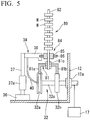
- FIG. 5 is a partial sectional view showing the deposition chamber 12 for explaining the rotation mechanism and a bias voltage applying mechanism.
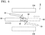
- FIG. 6 is a top view of the deposition region D for explaining the rotation mechanism.
- a roller conveyor 32 for conveying the conveyed carrier 80 is provided on the bottom portion of the deposition chamber 12.
- the roller conveyor 32 includes two conveying rollers 32a and 32b, and a shaft 32c which coaxially supports the conveying rollers 32a and 32b.
- the shaft 32c penetrates the side wall of the deposition chamber 12 to extend to the outside of the deposition chamber 12.
- a hermetic sealing member 12a is provided at the position where the shaft 32c penetrates the deposition chamber 12 and airtightly seals the outer periphery of the shaft 32c.
- the bias power source 17 is connected to the shaft 32c which protrudes toward the outside of the deposition chamber 12.
- the frame 81 of the conveyed carrier 80 includes two legs 81a and 81b extending downward.
- the rod 82 is supported by the frame 81 via a bearing 81c.
- the conveyed carrier 80 is conveyed by the roller conveyor 32 in a state where the leg 81a is supported by the conveying roller 32a and the leg 81b is supported by the conveying roller 32b.
- at least the conveying roller 32a is configured of a conductive member, and the conveying roller 32a is electrically connected to the frame 81 in the leg 81a.
- the interference member 34 stands upright on a bottom wall of the deposition chamber 12 in the vicinity of the roller conveyor 32.
- the interference member 34 includes an insulation member 36 fixed to the deposition chamber 12, a columnar support member 37 extending upward from the insulation member 36, and an arm member 38 horizontally extending from the upper end of the support member 37.
- At least the arm member 38 is configured of a conductive member and the arm member 38 is connected to the conveying roller 32a via a cable 40.
- an elastic member 37a is provided in the intermediate portion of the support member 37 in the longitudinal direction.
- the elastic member 37a alleviates the impact of the collision to prevent damages of the interference member 34.
- a rotation drive mechanism (not shown) which rotates the arm member 38 around the axis of the support member 37 is connected to the interference member 34.
- the arm member 38 can advance and retreat with respect to the carrier conveying line T. That is, as shown in FIG. 6 , the arm member 38 advances and retreats between a position where the arm member 38 does not interfere with the carrier conveying line T and a position where the arm member 38 partially shields the transport path of the rotation mechanism 84 (protrusion member 86).
- the conveyed carrier 80 enters the center portion (the center portion in the carrier conveying direction) of the deposition region D in a state where the arm member 38 advances into the carrier conveying line T, as shown in FIGS. 4 to 6 , the protrusion members 86 of the rotation mechanism 84 come into contact with the arm member 38. If the conveyed carrier 80 further advances therefrom, since the arm member 38 catches the protrusion member 86, the rotation mechanism 84 and the rod 82 rotates around the axis. Accordingly, the cutting tools W supported to the rod 82 rotate.
- the interference member 35 has the configuration similar to that of the interference member 34.
- the interference member 35 has an arm member 39 ( FIGS. 2 and 6 ) which is electrically connected to the bias power source 17.
- the interference member 35 is disposed in the direction approximately opposite to the interference member 34 in the carrier conveying direction.
- the arm member 39 of the interference member 35 extends toward the center portion of the deposition region D from the vicinity of a boundary between the heating region H2 and the deposition region D.
- the interference member 35 rotates the rod 82 of the conveyed carrier 80 entering the deposition region D from the heating region H2 in the center portion of the deposition region D.
- the rod 82 is rotated when the conveyed carrier 80 passes through the center portion of the deposition region D via the heating region H1 from the carrier-waiting region C1 and when the conveyed carrier 80 passes through the center portion of the deposition region D via the heating region H2 from the carrier-waiting region C2, and the cutting tools W are rotated during a film forming period.
- the interference member 34 and the interference member 35 interferes with the rotation mechanism 84 according to the conveying direction of the conveyed carrier 80.
- the conveyed carrier 80 is conveyed from the carrier-waiting region C1 to the deposition region D, only the arm member 38 of the interference member 34 advances into the carrier conveying line T to rotate the rod 82.
- the conveyed carrier 80 is conveyed from the carrier-waiting region C2 to the deposition region D, only the arm member 39 of the interference member 35 advances into the carrier conveying line T to rotate the rod 82.
- the case where only two interference members 34 and 35 are provided is described.
- the number of the installed interference members 34 and 35 is not particularly limited. It is possible to install as many interference members 34 and 35 as necessary to rotate all the rods 82 by the same number of times and the same angle during one film forming period.
- the installation positions (rotation position of the rod 82) of the interference members 34 and 35 are not limited to the center portion of the deposition region D, and the interference members 34 and 35 can be installed at arbitrary positions from the carrier-waiting region C1 to the carrier-waiting region C2.
- a vacuum pump 16, an air-releasing valve 29, and a gas source 27 are connected to the post-treatment chamber 13.
- the post-treatment chamber 13 is a cooling chamber in which the cutting tools W and the conveyed carrier 80 after the coating are cooled.
- the gas source 27 supplies gas for cooling a carrier into the post-treatment chamber 13.
- the deposition apparatus 100 of the present embodiment is suitably used for forming a hard coating film on the surface of a cutting tool.
- the cutting tool which is an object to be coated
- a cutting insert for example, there is a cutting insert, a drill, an end mill, a gear cutting tool, or the like.
- material of the cutting tool high speed steel, cemented carbide, cubic boron nitride, a cermet material, a ceramic material, or the like can be mentioned.
- coating film TiN, TiAl, TiAIN, TiCN, AlCr, AlCrN, or the like can be mentioned.
- the deposition apparatus 100 of the present embodiment it is possible to continuously form the coating film on the cutting tools W of the conveyed carrier 80 by reciprocating the conveyed carrier 80 between the carrier-waiting region C1 and the carrier-waiting region C2 to allow the conveyed carrier 80 to pass through the deposition region D a plurality of times.
- the cutting tools W are mounted on the conveyed carrier 80.
- the vacuum valves 52 and 53 are closed, and the pre-treatment chamber 11, the deposition chamber 12, and the post-treatment chamber 13 are held in a predetermined vacuum state (for example, approximately 1 ⁇ 10 .5 Pa).
- the air-releasing valve 28 of the pre-treatment chamber 11 is open and the inside of the pre-treatment chamber 11 becomes the atmospheric pressure.
- the entrance-side gate valve 51 is open in the state where the inside of the pre-treatment chamber 11 is the atmospheric pressure, and the conveyed carrier 80 is carried into the pre-treatment chamber 11.
- the conveyed carrier 80 is stopped at a position where the cutting tools W mounted on the conveyed carrier 80 confront with the heaters 21A and 21B.
- the entrance-side gate valve 51 is closed.
- the vacuum pump 14 is operated to evacuate the inside of the pre-treatment chamber 11 until the inside of the pre-treatment chamber 11 reaches a predetermined degree of vacuum (for example, approximately 1 ⁇ 10 -3 Pa)
- the heaters 21A and 21B are operated to heat the cutting tools W and the conveyed carrier 80 to a predetermined temperature.
- the cutting tools W can be uniformly heated from both sides by the heaters 21A and 21B. In this heating, the cutting tools W may be rotated by rotating the rod 82 around the axis.
- the vacuum valve 52 is open. Thereafter, the conveyed carrier 80 moves from the pre-treatment chamber 11 to the deposition chamber 12. The conveyed carrier 80 is stopped in the carrier-waiting region C1 inside the deposition chamber 12. After the conveyed carrier 80 is carried in, the vacuum valve 52 is closed. Thereafter, in order to carry the next conveyed carrier 80 into the pre-treatment chamber 11, the air-releasing valve 28 is open and the pre-treatment chamber 11 is returned to the atmospheric pressure. Thereafter, the entrance-side gate valve 51 is open to carry the conveyed carrier 80 into the pre-treatment chamber 11, and the above-described operations are repeated.
- the heaters 22A, 22B, 25A, and 25B are operated in a state where the conveyed carrier 80 is held in the carrier-waiting region C1. Moreover, the deposition region D is set to a state where the film formation with respect to the cutting tools W is possible. Specifically, a predetermined (for example, -300V) bias voltage is applied from the bias power source 17 to the cutting tools W via the frame 81. In this case, in the deposition apparatus 100 of the present embodiment, the bias power source 17, since the arm member 38 of the interference member 34, and the arm member 39 of the interference member 35 are electrically connected to each other, a predetermined bias voltage is also applied to the arm member 38. In addition, a process gas is supplied from the gas source 26 to the deposition chamber 12 and is controlled to a pressure condition (for example, 0.3 to 1 Pa) under which arc discharge is generated on the surfaces of the targets 23A, 23B, and 24A.
- a pressure condition for example, 0.3 to 1 Pa
- the cutting tools W are heated by the heaters 22A and 22B.
- the cutting tools W are heated to a temperature suitable for coating until the cutting tools W pass through the rear end (the end in the +Y direction) of the heating region H1.
- each of the heaters 22A and 22B is set to a length which allows the cutting tools W to be heated to a set temperature at a desired rate of temperature increase while the cutting tools W pass through the heating region H1.
- the width of each of the heaters 22A and 22B may be set to any length as long as the heaters can adjust the temperatures of the cutting tools W immediately before the film formation, and if the width is excessively increased, energy consumption increases.
- the widths of the heaters 22A and 22B are excessively increased and the heaters 22A and 22B are too close to the vacuum valve 52, an operation stability of the vacuum valve 52 is likely to be damaged due to heat. Accordingly, from the viewpoint of energy efficiency and a stable operation of the vacuum valve 52, preferably, the width of each of the heaters 22A and 22B is shorter than the width of the conveyed carrier 80 (length in the Y direction).
- the cutting tools W After the cutting tools W are heated to a predetermined temperature in the heating region HI, the cutting tools W continuously passes through the deposition region D.
- coating films having a desired composition are formed on the surfaces of the cutting tools W.
- a Ti target is used as the target and an N 2 containing gas is used as the process gas
- a TiN film is formed on the surfaces of the cutting tools W.
- the film thickness and the uniformity of the coating film can be controlled by a bias voltage, a gas pressure, a transport speed of the conveyed carrier 80, a rotation angle pitch of the cutting tool W, or the like.
- the cutting tools W sequentially pass through the deposition region D from the head side of the conveyed carrier 80, the cutting tools W are heated again in the heating region H2, and thereafter, the cutting tools W passes through the heating region H2 and enter the carrier-waiting region C2.
- the conveying direction of the conveyed carrier 80 is reversed at the time point when the cutting tools W mounted on the tail end of the conveyed carrier 80 reaches the center portion of the deposition region D. That is, the conveying direction of the conveyed carrier 80 is changed in a direction from the carrier-waiting region C2 toward the carrier-waiting region C1. In this case, the operation states of the heating regions H1 and H2 and the deposition region D are maintained without being stopped. Accordingly, in the present embodiment, some cutting tools W positioned on the tail side of the conveyed carrier 80 are not heated in the heating region H2.
- the turning in the traveling direction of the conveyed carrier 80 may be performed at a position other than the above-described position.
- the turning may be performed at the time when the tail end of the conveyed carrier 80 comes out from the deposition region D.
- coating films are sequentially laminated from the cutting tools W positioned in the carrier-waiting region C1. That is, coating in the deposition region D is sequentially performed from the cutting tools W positioned on the head side (the end portion on the carrier-waiting region C1 side) in the conveying direction of the conveyed carrier 80.
- the heating in the heating region H2 and the coating in the deposition region D are performed on the cutting tools W positioned in the carrier-waiting region C2 at the time when the conveyed carrier 80 is reversed, and the rotation operation is performed by the interference between the interference member 35 and the protrusion members 86 during the coating.
- the conveying direction of the conveyed carrier 80 is reversed again at the time point when the cutting tools W mounted on the tail end (the end portion on the carrier-waiting region C2 side) of the conveyed carrier 80 reaches the center portion of the deposition region D. That is, the conveying direction of the conveyed carrier 80 is changed again in the direction from the carrier-waiting region C2 toward the carrier-waiting region C1.
- the turning in the traveling direction of the conveyed carrier 80 may be performed at the time point when the tail end of the conveyed carrier 80 comes out from the deposition region D.
- the coating films are sequentially laminated from the cutting tools W positioned on the carrier-waiting region C2 side. That is, the coating in the deposition region D is sequentially performed from the cutting tools W positioned on the head side (the end portion on the carrier-waiting region C2 side) in the conveying direction of the conveyed carrier 80, and the rotation operation (approximately 60° around the axis) is performed by the interference between the interference member 34 and the protrusion member 86 during the coating.
- the heating in the heating region H1 and the coating in the deposition region D are sequentially performed on the cutting tools W positioned in the carrier-waiting region C1 or the heating region H1 at the time point when the conveyed carrier 80 is reversed again.
- the conveyed carrier 80 reciprocates one and a half between the carrier-waiting region C1 and the carrier-waiting region C2 and passes through the deposition region D three times.
- coating is applied to the peripheral surface of the cutting tool W in a total of 720°. That is, two layers of the coating are uniformly applied to each portion of the cutting tool W.
- the coating ends. Specifically, applying of the bias voltage and arc discharge with respect to the cutting tools W are stopped.
- the vacuum valve 53 between the deposition chamber 12 and the post-treatment chamber 13 is open, and the conveyed carrier 80 is fed out to the post-treatment chamber 13. If the conveyed carrier 80 is carried into the post-treatment chamber 13, the vacuum valve 53 is closed. An operation of opening the vacuum valve 52 between the pre-treatment chamber 11 and the deposition chamber 12 and carrying the next conveyed carrier 80 into the deposition chamber 12 may be performed together with this transport operation.
- the conveyed carrier 80 carried from the deposition chamber 12 into the post-treatment chamber 13 is stopped in the post-treatment chamber 13 to be cooled.
- the cooling is performed by maintaining a pressure during a predetermined time while supplying a cooling gas from the gas source 27 into the post-treatment chamber 13.
- a cooling gas an inert gas can be used.
- the air-releasing valve 29 is open and the pressure inside the post-treatment chamber 13 is returned to the atmospheric pressure. Thereafter, the outlet side gate valve 54 is open and the conveyed carrier 80 is carried out from the post-treatment chamber 13. After the conveyed carrier 80 is carried out, an evacuation operation in the post-treatment chamber 13 is performed by the vacuum pump 16. Thereafter, a predetermined degree of vacuum (for example, 1 ⁇ 10 -3 Pa) is maintained in the post-treatment chamber 13 until the next conveyed carrier 80 is carried into the post-treatment chamber 13.
- a predetermined degree of vacuum for example, 1 ⁇ 10 -3 Pa
- One conveyed carrier 80 can be accommodated in each of the pre-treatment chamber 11, the deposition chamber 12, and the post-treatment chamber 13 of the deposition apparatus 100 of the present embodiment.
- the heating in the pre-treatment chamber 11, the coating in the deposition chamber 12, and the cooling in the post-treatment chamber 13 can be performed together.
- it is possible to effectively perform the coating on the cutting tools W by repeating the transport of the conveyed carrier 80, and the heating, the coating, and the cooling in each chamber.
- the case where the direction of the conveyed carrier 80 is switched twice and the conveyed carrier 80 passes through the deposition region D three times is described.
- the reciprocation of the conveyed carrier 80 can be repeated as many times as necessary.
- the number of film formations on the surface of the cutting tool W may be adjusted to be uniform by changing the number (the rotation pitch) of the protrusion members 86 according to the number of times of the reciprocations.
- the deposition apparatus 100 of the above-described present embodiment it is possible to transport the conveyed carrier 80 while rotating the cutting tools W on the conveyed carrier 80. Accordingly, it is possible to continuously perform the heating and the film forming processing of the coating film with respect to the cutting tools W while switching the side surfaces of the cutting tools W facing the targets (23A, 23B, and 24A) by reciprocating the conveyed carrier 80 between the carrier-waiting regions C1 and C2.
- the cutting tool W rotates by a predetermined angle at least once during the formation of the coating film, it is possible to more uniformly form the coating film.
- the arm members 38 and 39 and the bias power source 17 are electrically connected to each other. Accordingly, since the arm members 38 and 39 and the protrusion members 86 of the conveyed carrier 80 can be maintained at the same potential, it is possible to prevent a voltage of the conveyed carrier 80 from decreasing due to spark generated when the arm member 38 or the arm member 39 comes into contact with the protrusion members 86.
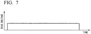
- FIG. 7 is a graph showing a change of a bias voltage of the conveyed carrier 80 in the deposition apparatus 100 of the present embodiment.
- FIG. 8 is a graph showing the change of the bias voltage in the conveyed carrier 80 in a configuration in which the arm members 38 and 39 and the bias power source 17 are not connected to each other.
- the bias voltage of the conveyed carrier 80 can be approximately constantly maintained during the film forming period.
- the bias voltage is abruptly changed and is greatly changed between the applied voltage (maximum value) and approximately 0 V. This is because spark is generated between the arm members 38 and 39 and the protrusion members 86 at the moment when the arm members 38 and 39 and the protrusion members 86 come into contact with each other and the charge on the conveyed carrier 80 side is released.
- the interference members 34 and 35 and the rotation mechanism 84 interfere with each other at the center portion of the deposition region D. If a decrease in the bias voltage is generated by spark due to the conditions, it is not possible to form a coating film having a desired film quality on the surfaces of the cutting tools W.
- the deposition apparatus 100 of the present embodiment since the arm members 38 and 39 and the protrusion members 86 have the same potential, it is possible to prevent the spark generated when the arm members 38 and 39 and the protrusion members 86 come into contact with each other. As a result, as shown in FIG. 7 , since the bias voltage is maintained constantly, it is possible to stably form the coating film having a desired film quality on the surfaces of the cutting tools W. Therefore, according to the deposition apparatus 100 of the present embodiment, it is possible to form the coating film having a high quality.
- the rod 82 positioned closer to the head side than the rod 82 may be positioned in the deposition region D at the moment when one rod 82 rotates. Accordingly, even in a case where the rod 82 rotates outside the deposition region D, there is a concern that the bias voltages of the cutting tools W during the film formation are changed. Accordingly, like the present embodiment, preferably, the bias voltage is applied to the arm members 38 and 39.
- the heating regions H1 and H2 are provided on both sides (-Y direction side and +Y direction side in the drawings) of the deposition region D of the deposition chamber 12 in the carrier conveying direction, it is possible to heat the cutting tools W to a predetermined temperature immediately before the film is formed. Accordingly, it is possible to adjust the cutting tools W of all conveyed carriers 80 to a constant temperature immediately before the coating is performed.
- the temperature of the cutting tools W on the conveyed carrier 80 is approximately constant immediately after the cutting tools W are heated in the pre-treatment chamber 11. However, it takes times until the cutting tools W on the head side of the conveyed carrier 80 and the cutting tools W on the tail side enter the deposition region D after the cutting tools W are heated. Accordingly, differences are generated between the film formation temperatures of the cutting tools on the head side of the conveyed carrier 80 and the film formation temperatures of the cutting tools W on the tail side, and the differences are likely to influence the film quality of the coating film.
- all the cutting tools can always enter the deposition region D at a constant temperature by heating in the heating region HI. Accordingly, since the coating can be performed under a constant temperature condition, it is possible to prevent the quality of the coating film for each cutting tool W from being dispersed and form the coating film with a high yield.
- the temperature is low when the film formation starts, and the temperature of the cutting tool W is suddenly increased due to heat generation generated by the arc discharge or the bias application in the deposition region D. Accordingly, since the coating film is formed under a low temperature condition at the beginning of the film formation, there is a concern that the coating film having low adhesion or a low film quality is formed.
- the coating can be performed at an optimum temperature from the beginning of the film formation to the end thereof, and it is possible to form the coating film having a high quality.
- the plurality of rods 82 of the conveyed carrier 80 are arranged in the upright posture along the carrier conveying direction, and the cutting tools W are supported by the rods 82. Accordingly, the distances between the cutting tools W passing through the deposition region D and the targets (23A, 23B, and 24A) are approximately constantly held. Accordingly, not only the film formation temperature of each cutting tool W but also other film formation conditions are constant. Accordingly, it is possible to more uniformly form the coating film in the film thickness direction.
- the present invention it is possible to stably apply a bias voltage to a workpiece, and the deposition apparatus which can form a coating film having a high quality is provided.
- the method for manufacturing the cutting tool including the coating film having a high quality is provided.
- the present invention has industrial applicability.
Landscapes
- Chemical & Material Sciences (AREA)
- Engineering & Computer Science (AREA)
- Mechanical Engineering (AREA)
- Chemical Kinetics & Catalysis (AREA)
- Materials Engineering (AREA)
- Metallurgy (AREA)
- Organic Chemistry (AREA)
- General Chemical & Material Sciences (AREA)
- Physical Vapour Deposition (AREA)
- Cutting Tools, Boring Holders, And Turrets (AREA)
Abstract
Description
- The present invention relates to a deposition apparatus and a method for manufacturing a coated cutting tool.
- Priority is claimed on Japanese Patent Application No.
2015-012602, filed on January 26, 2015 - A deposition apparatus is known which applies coating to a surface of a cutting tool while rotating the cutting tool (for example, refer to PTL 1). In an ion plating device described in PTL 1, an interference member is provided in the vicinity of a path of a carrier frame while a gear-shaped rotating wheel is provided on a table shaft supporting a workpiece. The interference member and the rotating wheel come into contact with each other according to the movement of the carrier frame, and the workpiece is rotated by the rotation of the rotating wheel.
- [PTL 1] Japanese Unexamined Patent Application, First Publication No.
H6-322537 - In a film forming process of a cutting tool, coating is performed while applying a bias voltage to a workpiece. However, if the coating is performed while applying the bias voltage to the carrier frame in the ion plating device described in PTL 1, it has been found that the bias voltage is irregularly changed during the movement of the carrier frame. If the bias voltage is changed during the coating, there is a concern that a coating film having a desired film quality cannot be obtained.
- An object of the present invention is to provide a deposition apparatus capable of forming a coating film having a high quality by stably holding a bias voltage when coating is performed while a workpiece is rotated.
- Another object of the present invention is to provide a method for manufacturing a cutting tool including a coating film having a high quality.
- According to an aspect of the present invention, there is provided a deposition apparatus, including: a deposition chamber which includes a deposition region for forming a coating film on an object to be coated; a conveying device which conveys a conveyed carrier supporting the object to be coated; and a bias power source which applies a bias voltage to the object to be coated via the conveyed carrier, in which the coating film is formed by allowing the conveyed carrier to pass through the deposition region while applying a bias voltage to the object to be coated, a plurality of rods which support the object to be coated and rotate around axes are disposed in the conveyed carrier along a carrier conveying direction in an upright posture, a protrusion member protruding to the outside in a radial direction is provided on an outer peripheral surface of the rod, an interference member which catches the protrusion member of the conveyed carrier moving in the deposition chamber and rotates the rod around the axis is provided on a wall surface of the deposition chamber via an insulation member, and the interference member and the bias power source are electrically connected to each other.
- According to this configuration, since the interference member and the protrusion member of the conveyed carrier can be maintained at the same potential, it is possible to prevent a voltage of the conveyed carrier from decreasing due to spark generated when the interference member and the protrusion member come into contact with each other. Therefore, it is possible to form a coating film having a high quality.
- The conveying device may include a plurality of conveying rollers disposed along a conveying direction of the conveyed carrier, and the interference member and the bias power source may be electrically connected to each other via one conveying roller or the plurality of conveying rollers.
- The interference member may be provided at a position where the interference member rotates the rod passing through the deposition region.
- The interference member may rotate the rod at a center portion of the deposition region in the carrier conveying direction.
- A plurality of protrusion members may be provided at equal intervals in circumferential directions of the rods.
- The deposition chamber may include a heating region which is disposed to be adjacent to the deposition region in the carrier conveying direction and heats the object to be coated before the object to be coated enters the deposition region, and a carrier-waiting region which accommodates the conveyed carrier between the deposition region and an end portion of the deposition chamber.
- The heating regions may be provided on both sides of the deposition region in the carrier conveying direction.
- According to another aspect of the present invention, there is provided a method for manufacturing a coated cutting tool, using a deposition apparatus including a deposition chamber which forms a coating film on an object to be coated, a conveying device which conveys a conveyed carrier supporting the object to be coated, and a bias power source which applies a bias voltage to the object to be coated via the conveyed carrier, in which a plurality of rods which support the object to be coated and rotate around axes are disposed in the conveyed carrier along a carrier conveying direction in an upright posture, a protrusion member protruding to the outside in a radial direction is provided on an outer peripheral surface of the rod, and an interference member which catches the protrusion member and rotates the rod around the axis is provided on a wall surface of the deposition chamber, the method including: a process of mounting the cutting tool on the conveyed carrier; a process of conveying the conveyed carrier into the deposition chamber and allowing the conveyed carrier to pass through the deposition region; and a process of allowing the interference member and the protrusion member to interfere with each other and to rotate the rod in a state where the bias voltage is applied to the cutting tool and the interference member.
- According to this method, since the interference member and the protrusion member of the conveyed carrier can be maintained at the same potential, it is possible to prevent a voltage of the conveyed carrier from decreasing due to spark generated when the interference member and the protrusion member come into contact with each other. Therefore, it is possible to manufacture a cutting tool including a coating film having a high quality.
- In the manufacturing method, the rod may be rotated while passing through the deposition region.
- In the manufacturing method, the rod may be rotated at the center portion of the deposition region in the carrier conveying direction.
- In the manufacturing method, the conveyed carrier may be conveyed into the deposition chamber and may be sequentially passed through a heating region heating the cutting tool and the deposition region.
- In the manufacturing method, the heating region may be disposed on both sides in a conveying direction of the conveyed carrier with respect to the deposition region, and a plurality of layers of coating films may be formed on the cutting tool by reciprocating the conveyed carrier with respect to a region including a plurality of heating regions and deposition regions.
- According to the present invention, it is possible to stably apply a bias voltage to a workpiece, and the deposition apparatus which can form a coating film having a high quality is provided.
- According to the present invention, the method for manufacturing the cutting tool including the coating film having a high quality is provided.
-
-
FIG. 1 is a side view showing an internal structure of a deposition apparatus according to an embodiment. -
FIG. 2 is a top view showing the internal structure of the deposition apparatus according to the embodiment. -
FIG. 3 is a side view showing a structure of a conveyed carrier. -
FIG. 4 is a view showing a support aspect of a cutting tool W. -
FIG. 5 is a partial sectional view showing a deposition chamber for explaining a rotation mechanism and a bias voltage applying mechanism. -
FIG. 6 is a top view of the deposition chamber for explaining a rotation operation. -
FIG. 7 is a graph showing a change of a bias voltage of the conveyed carrier in the deposition apparatus of the embodiment. -
FIG. 8 is a graph showing the change of the bias voltage in the conveyed carrier in a configuration in which an arm member and a bias power source are not connected to each other. - Hereinafter, a deposition apparatus and a method for manufacturing a cutting tool according to an embodiment will be described with reference to the drawings.
-
FIG. 1 is a side view showing an internal structure of a deposition apparatus according to an embodiment.FIG. 2 is a top view showing the internal structure of the deposition apparatus according to the embodiment.FIG. 3 is a side view showing a structure of a conveyed carrier. - A
deposition apparatus 100 of the present embodiment shown inFIGS. 1 and2 is an in-line deposition apparatus which performs film forming processing on a cutting tool W while conveying a conveyedcarrier 80 on which the cutting tool W are mounted. - As shown in
FIG.3 , the conveyedcarrier 80 includes arectangular frame 81 and a plurality of (five in the shown example)rods 82 which are disposed inside theframe 81 in an upright posture. Cutting tools W which are objects to which a coating film (a coating film for a cutting tool) is to be formed are inserted into eachrod 82 so as to be supported. - Here,
FIG. 4 is a view showing a support aspect of the cutting tools W. The plurality of cutting tools W are disposed in therod 82 in a state where cylindrical spacers S are interposed between the cutting tools W adjacent to each other. Therod 82 is rotatable around the axis. Arotation mechanism 84 for rotating therod 82 is provided on the lower portion of therod 82. Therotation mechanism 84 includes acylindrical support portion 85 which is fixed to therod 82, and sixprotrusion members 86 which are provided on an outer peripheral surface of thesupport portion 85 at equal intervals in a circumferential direction. All of theprotrusion members 86 extend from thesupport portion 85 in the radial direction of therod 82 and are orthogonal to therod 82. Accordingly, in the present embodiment, it is possible to rotate the cutting tools W at a pitch of approximately 60°. - The number or the disposition angle of the
protrusion members 86 can be appropriately changed according to the rotation aspects of the cutting tools W. For example, the installation number of theprotrusion members 86 may be four or eight, and the plurality ofprotrusion members 86 may be disposed at irregular intervals in the circumferential direction of therod 82. - In the present embodiment, the cutting tool W is a cutting insert which is used in a cutting edge-replaceable cutting tool. The cutting insert is a polygonal plate-shaped member which is formed of a hard material such as cemented carbide and a circular attachment hole for attaching the cutting insert to a cutting tool body is formed in the cutting insert. As shown in
FIG. 3 , in the present embodiment, therod 82 is inserted into attachment holes h of the cutting tools W. - As shown in
FIGS. 1 and2 , thedeposition apparatus 100 includes apre-treatment chamber 11, adeposition chamber 12, and apost-treatment chamber 13. Thepre-treatment chamber 11 and thedeposition chamber 12 connected to each other via avacuum valve 52, and thedeposition chamber 12 and thepost-treatment chamber 13 are connected to each other via avacuum valve 53. An entrance-side gate valve 51 for introducing the conveyedcarrier 80 into thedeposition apparatus 100 is provided in thepre-treatment chamber 11. An outletside gate valve 54 for discharging the conveyedcarrier 80 is provided in thepost-treatment chamber 13. - Roller conveyors (conveying devices) 31 to 33 in which a plurality of conveying rollers are juxtaposed are laid on the bottom portion sides of the
pre-treatment chamber 11, thedeposition chamber 12, and thepost-treatment chamber 13. The conveyedcarrier 80 is conveyed on theroller conveyors 31 to 33. In the present embodiment, a path of the conveyedcarrier 80 on theroller conveyors 31 to 33 configure a linear carrier conveying line T. The conveyedcarrier 80 on which the cutting tools W are mounted is sequentially conveyed to thepre-treatment chamber 11, thedeposition chamber 12, and thepost-treatment chamber 13 along the carrier conveying line T. - A vacuum pump 14 and an air-releasing
valve 28 are connected to thepre-treatment chamber 11. Aheater 21A and aheater 21B for heating the cutting tools W for each conveyedcarrier 80 are provided inside thepre-treatment chamber 11. In the case of the present embodiment, the cutting tools W are heated from both sides of the conveyedcarrier 80 by theheaters heaters carrier 80 in a carrier conveying direction (Y direction in the drawings). In addition, each of theheaters carrier 80 are held in a vertical direction (Z direction in the drawings). That is, theheaters carrier 80. - A
vacuum pump 15, agas source 26, and abias power source 17 are connected to thedeposition chamber 12. A carrier-waiting region C1, a heating region H1, a deposition region D, a heating region H2, and a carrier-waiting region C2 are disposed inside thedeposition chamber 12 along the carrier conveying line T in this order. Aninterference member 34 and aninterference member 35 are installed in the vicinity of the carrier conveying line T in the deposition region D. As shown inFIG. 2 , theinterference member 34 and theinterference member 35 are disposed on sides opposite to each other in a state where the carrier conveying line T is interposed therebetween. - In the present specification, the "deposition region" indicates a region inside the deposition chamber having a function for forming a single coating film layer on the surface of the cutting tool W. Accordingly, even in a case where the number of targets or the disposition state of the targets is changed, if a single coating film layer is formed on the surface of the cutting tool W, the region is not determined by the targets, and the region becomes one "deposition region". For example, in the deposition region D, a plurality of targets of the same kind may be disposed to be arranged in the carrier conveying direction (Y direction).
- The carrier-waiting region C1 is a region in which the conveyed
carrier 80 is temporarily stopped before the heating region H1. The carrier-waiting region C2 is a region in which the conveyedcarrier 80 is temporarily stopped after the heating region H2. In addition, the carrier-waiting regions C1 and C2 are regions in which the conveyedcarrier 80 is temporarily stopped after the formation of the coating film. - The carrier-waiting region C1 is formed to have a length capable of accommodating the conveyed
carrier 80 between thevacuum valve 52 and the deposition region D. Preferably, the carrier-waiting region C1 is formed to have a length capable of accommodating the conveyedcarrier 80 between thevacuum valve 52 and the heating region H1. - The carrier-waiting region C2 is formed to have a length capable of accommodating the conveyed
carrier 80 between the deposition region D and thevacuum valve 53. Preferably, the carrier-waiting region C2 is formed to have a length capable of accommodating the conveyedcarrier 80 between the heating region H2 and thevacuum valve 53. - The heating regions H1 and H2 are regions in which the cutting tools W are heated immediately before the deposition region D. As shown in
FIG. 2 , in the heating region HI, a heater (heating device) 22A and a heater (heating device) 22B are provided such that the carrier conveying line T is interposed therebetween. Theheaters carrier 80 which is conveyed from the carrier-waiting region C1 to the deposition region D. - In the heating region H2, a heater (heating device) 25A and a heater (heating device) 25B are provided such that the carrier conveying line T is interposed therebetween. The
heaters carrier 80 which is conveyed from the carrier-waiting region C2 to the deposition region D. - In the case of the present embodiment, the cutting tools W are heated by allowing the conveyed
carrier 80 to pass through a portion between theheaters heaters heaters carrier 80. The height (the length in the Z direction) of each of theheaters carrier 80 are held. - The deposition region D is a region in which coating is performed on the cutting tools W by arc ion plating method. In the case of the present embodiment, four targets are disposed in the deposition region D. As shown in
FIG. 2 , a pair oftargets FIG. 1 , atarget 24A is disposed below (-Z direction) thetarget 23A vertically. Although not shown, a target is also disposed to face thetarget 24A below thetarget 23B vertically. - In addition, in the present embodiment, the plurality of circular targets are installed to form the deposition region D. However, the shape of the target is not limited to a circular shape. For example, a rectangular target elongated in the upward-downward direction (the Z direction in the drawings) of the
deposition chamber 12 may be used. In addition, three or more targets may be disposed to be arranged in the upward-downward direction of thedeposition chamber 12. - An arc power source (not shown) which supplies arc discharge power to the targets (23A, 23B, and 24A) is provided in the deposition region D. The
bias power source 17 applies a bias voltage to the cutting tools W via the conveyedcarrier 80 when the conveyedcarrier 80 is positioned at least at the deposition region D. -
FIG. 5 is a partial sectional view showing thedeposition chamber 12 for explaining the rotation mechanism and a bias voltage applying mechanism.FIG. 6 is a top view of the deposition region D for explaining the rotation mechanism. - As shown in
FIG. 5 , aroller conveyor 32 for conveying the conveyedcarrier 80 is provided on the bottom portion of thedeposition chamber 12. In the case of the present embodiment, theroller conveyor 32 includes two conveyingrollers shaft 32c which coaxially supports the conveyingrollers shaft 32c penetrates the side wall of thedeposition chamber 12 to extend to the outside of thedeposition chamber 12. Ahermetic sealing member 12a is provided at the position where theshaft 32c penetrates thedeposition chamber 12 and airtightly seals the outer periphery of theshaft 32c. Thebias power source 17 is connected to theshaft 32c which protrudes toward the outside of thedeposition chamber 12. - The
frame 81 of the conveyedcarrier 80 includes twolegs rod 82 is supported by theframe 81 via abearing 81c. The conveyedcarrier 80 is conveyed by theroller conveyor 32 in a state where theleg 81a is supported by the conveyingroller 32a and theleg 81b is supported by the conveyingroller 32b. In the present embodiment, at least the conveyingroller 32a is configured of a conductive member, and the conveyingroller 32a is electrically connected to theframe 81 in theleg 81a. Accordingly, the conveyedcarrier 80 and thebias power source 17 are electrically connected to each other via the conveyingroller 32a and theshaft 32c. All of theframe 81, thebearing 81c, and therod 82 in the conveyedcarrier 80 are configured of conductive members, and the bias voltage supplied from the conveyingroller 32a is applied to the cutting tools W through therod 82. - The
interference member 34 stands upright on a bottom wall of thedeposition chamber 12 in the vicinity of theroller conveyor 32. Theinterference member 34 includes aninsulation member 36 fixed to thedeposition chamber 12, acolumnar support member 37 extending upward from theinsulation member 36, and anarm member 38 horizontally extending from the upper end of thesupport member 37. At least thearm member 38 is configured of a conductive member and thearm member 38 is connected to the conveyingroller 32a via acable 40. In the case of the present embodiment, anelastic member 37a is provided in the intermediate portion of thesupport member 37 in the longitudinal direction. When thesupport member 37 or thearm member 38 receives impact, for example, when thesupport member 37 or thearm member 38 collides with the conveyedcarrier 80, theelastic member 37a alleviates the impact of the collision to prevent damages of theinterference member 34. A rotation drive mechanism (not shown) which rotates thearm member 38 around the axis of thesupport member 37 is connected to theinterference member 34. - The
arm member 38 can advance and retreat with respect to the carrier conveying line T. That is, as shown inFIG. 6 , thearm member 38 advances and retreats between a position where thearm member 38 does not interfere with the carrier conveying line T and a position where thearm member 38 partially shields the transport path of the rotation mechanism 84 (protrusion member 86). The conveyedcarrier 80 enters the center portion (the center portion in the carrier conveying direction) of the deposition region D in a state where thearm member 38 advances into the carrier conveying line T, as shown inFIGS. 4 to 6 , theprotrusion members 86 of therotation mechanism 84 come into contact with thearm member 38. If the conveyedcarrier 80 further advances therefrom, since thearm member 38 catches theprotrusion member 86, therotation mechanism 84 and therod 82 rotates around the axis. Accordingly, the cutting tools W supported to therod 82 rotate. - The
interference member 35 has the configuration similar to that of theinterference member 34. Theinterference member 35 has an arm member 39 (FIGS. 2 and6 ) which is electrically connected to thebias power source 17. Theinterference member 35 is disposed in the direction approximately opposite to theinterference member 34 in the carrier conveying direction. Thearm member 39 of theinterference member 35 extends toward the center portion of the deposition region D from the vicinity of a boundary between the heating region H2 and the deposition region D. Theinterference member 35 rotates therod 82 of the conveyedcarrier 80 entering the deposition region D from the heating region H2 in the center portion of the deposition region D. That is, in thedeposition apparatus 100 of the present embodiment, therod 82 is rotated when the conveyedcarrier 80 passes through the center portion of the deposition region D via the heating region H1 from the carrier-waiting region C1 and when the conveyedcarrier 80 passes through the center portion of the deposition region D via the heating region H2 from the carrier-waiting region C2, and the cutting tools W are rotated during a film forming period. - Only any one of the
interference member 34 and theinterference member 35 interferes with therotation mechanism 84 according to the conveying direction of the conveyedcarrier 80. When the conveyedcarrier 80 is conveyed from the carrier-waiting region C1 to the deposition region D, only thearm member 38 of theinterference member 34 advances into the carrier conveying line T to rotate therod 82. When the conveyedcarrier 80 is conveyed from the carrier-waiting region C2 to the deposition region D, only thearm member 39 of theinterference member 35 advances into the carrier conveying line T to rotate therod 82. - In the present embodiment, the case where only two
interference members interference members many interference members rods 82 by the same number of times and the same angle during one film forming period. In addition, the installation positions (rotation position of the rod 82) of theinterference members interference members - As shown in
FIG. 1 , avacuum pump 16, an air-releasingvalve 29, and agas source 27 are connected to thepost-treatment chamber 13. Thepost-treatment chamber 13 is a cooling chamber in which the cutting tools W and the conveyedcarrier 80 after the coating are cooled. Thegas source 27 supplies gas for cooling a carrier into thepost-treatment chamber 13. - Next, a film forming method using the
deposition apparatus 100 of the present embodiment will be described. - The
deposition apparatus 100 of the present embodiment is suitably used for forming a hard coating film on the surface of a cutting tool. - For example, as the cutting tool which is an object to be coated, there is a cutting insert, a drill, an end mill, a gear cutting tool, or the like. As the material of the cutting tool, high speed steel, cemented carbide, cubic boron nitride, a cermet material, a ceramic material, or the like can be mentioned. For example, as the coating film, TiN, TiAl, TiAIN, TiCN, AlCr, AlCrN, or the like can be mentioned.
- In the
deposition apparatus 100 of the present embodiment, it is possible to continuously form the coating film on the cutting tools W of the conveyedcarrier 80 by reciprocating the conveyedcarrier 80 between the carrier-waiting region C1 and the carrier-waiting region C2 to allow the conveyedcarrier 80 to pass through the deposition region D a plurality of times. - Hereinafter, this will be described in detail.
- First, as shown in
FIG. 1 , the cutting tools W are mounted on the conveyedcarrier 80. In this case, in thedeposition apparatus 100, thevacuum valves pre-treatment chamber 11, thedeposition chamber 12, and thepost-treatment chamber 13 are held in a predetermined vacuum state (for example, approximately 1 × 10.5 Pa). - Next, the air-releasing
valve 28 of thepre-treatment chamber 11 is open and the inside of thepre-treatment chamber 11 becomes the atmospheric pressure. Thereafter, the entrance-side gate valve 51 is open in the state where the inside of thepre-treatment chamber 11 is the atmospheric pressure, and the conveyedcarrier 80 is carried into thepre-treatment chamber 11. The conveyedcarrier 80 is stopped at a position where the cutting tools W mounted on the conveyedcarrier 80 confront with theheaters side gate valve 51 is closed. Thereafter, the vacuum pump 14 is operated to evacuate the inside of thepre-treatment chamber 11 until the inside of thepre-treatment chamber 11 reaches a predetermined degree of vacuum (for example, approximately 1 × 10⁻³ Pa) - If the inside of the
pre-treatment chamber 11 reaches a predetermined degree of vacuum, theheaters carrier 80 to a predetermined temperature. In the present embodiment, the cutting tools W can be uniformly heated from both sides by theheaters rod 82 around the axis. - If the cutting tools W are heated to a predetermined temperature, the
vacuum valve 52 is open. Thereafter, the conveyedcarrier 80 moves from thepre-treatment chamber 11 to thedeposition chamber 12. The conveyedcarrier 80 is stopped in the carrier-waiting region C1 inside thedeposition chamber 12. After the conveyedcarrier 80 is carried in, thevacuum valve 52 is closed. Thereafter, in order to carry the next conveyedcarrier 80 into thepre-treatment chamber 11, the air-releasingvalve 28 is open and thepre-treatment chamber 11 is returned to the atmospheric pressure. Thereafter, the entrance-side gate valve 51 is open to carry the conveyedcarrier 80 into thepre-treatment chamber 11, and the above-described operations are repeated. - Next, in the
deposition chamber 12, coating is performed on the cutting tools W. - In the
deposition chamber 12, theheaters carrier 80 is held in the carrier-waiting region C1. Moreover, the deposition region D is set to a state where the film formation with respect to the cutting tools W is possible. Specifically, a predetermined (for example, -300V) bias voltage is applied from thebias power source 17 to the cutting tools W via theframe 81. In this case, in thedeposition apparatus 100 of the present embodiment, thebias power source 17, since thearm member 38 of theinterference member 34, and thearm member 39 of theinterference member 35 are electrically connected to each other, a predetermined bias voltage is also applied to thearm member 38. In addition, a process gas is supplied from thegas source 26 to thedeposition chamber 12 and is controlled to a pressure condition (for example, 0.3 to 1 Pa) under which arc discharge is generated on the surfaces of thetargets - Thereafter, the transport of the conveyed
carrier 80 to the heating region H1 side starts. - Thereafter, when the conveyed
carrier 80 passes through the heating region HI, the cutting tools W are heated by theheaters - Accordingly, the width (the length in the Y direction) of each of the
heaters - The width of each of the
heaters heaters heaters vacuum valve 52, an operation stability of thevacuum valve 52 is likely to be damaged due to heat. Accordingly, from the viewpoint of energy efficiency and a stable operation of thevacuum valve 52, preferably, the width of each of theheaters - After the cutting tools W are heated to a predetermined temperature in the heating region HI, the cutting tools W continuously passes through the deposition region D. When the cutting tool W passes through the deposition region D, coating films having a desired composition are formed on the surfaces of the cutting tools W. For example, in a case where a Ti target is used as the target and an N2 containing gas is used as the process gas, a TiN film is formed on the surfaces of the cutting tools W. The film thickness and the uniformity of the coating film can be controlled by a bias voltage, a gas pressure, a transport speed of the conveyed
carrier 80, a rotation angle pitch of the cutting tool W, or the like. - In the present embodiment, when the cutting tools W on the conveyed
carrier 80 pass through the center portion of the deposition region D, since therotation mechanism 84 interferes with thearm member 38, the cutting tools W rotate approximately 60° around the axes and are stopped. In this case, since the bias voltage is also applied to thearm member 38, thearm member 38 and theprotrusion members 86 having the same potential come into contact with each other. In the case of the present embodiment, since the cutting tool W rotates by 60° around the axes in the center portion of the deposition region D, the side surfaces of the cutting tool W which are shifted by 60° in a first half and a second half of a period of passing through the deposition region D face the targets. That is, coating is performed on the region of 240° (60° × 2 × 2 surfaces) among the peripheral surface 360° of the cutting tool W while the cutting tool W passes through the deposition region D once. - After the cutting tools W sequentially pass through the deposition region D from the head side of the conveyed
carrier 80, the cutting tools W are heated again in the heating region H2, and thereafter, the cutting tools W passes through the heating region H2 and enter the carrier-waiting region C2. In the present embodiment, the conveying direction of the conveyedcarrier 80 is reversed at the time point when the cutting tools W mounted on the tail end of the conveyedcarrier 80 reaches the center portion of the deposition region D. That is, the conveying direction of the conveyedcarrier 80 is changed in a direction from the carrier-waiting region C2 toward the carrier-waiting region C1. In this case, the operation states of the heating regions H1 and H2 and the deposition region D are maintained without being stopped. Accordingly, in the present embodiment, some cutting tools W positioned on the tail side of the conveyedcarrier 80 are not heated in the heating region H2. - The turning in the traveling direction of the conveyed
carrier 80 may be performed at a position other than the above-described position. For example, the turning may be performed at the time when the tail end of the conveyedcarrier 80 comes out from the deposition region D. - If the conveying direction of the conveyed
carrier 80 is reversed, continuously, coating films are sequentially laminated from the cutting tools W positioned in the carrier-waiting region C1. That is, coating in the deposition region D is sequentially performed from the cutting tools W positioned on the head side (the end portion on the carrier-waiting region C1 side) in the conveying direction of the conveyedcarrier 80. The heating in the heating region H2 and the coating in the deposition region D are performed on the cutting tools W positioned in the carrier-waiting region C2 at the time when the conveyedcarrier 80 is reversed, and the rotation operation is performed by the interference between theinterference member 35 and theprotrusion members 86 during the coating. In the rotation operation in this backward path, in the center portion of the deposition region D, theprotrusion members 86 of therotation mechanism 84 and thearm member 39 of theinterference member 35 come into contact with each other, and therod 82 and the cutting tools W rotate approximately 60° around the axis. In this case, theprotrusion members 86 and thearm member 39 having the same potential come into contact with each other. - Thereafter, the conveying direction of the conveyed
carrier 80 is reversed again at the time point when the cutting tools W mounted on the tail end (the end portion on the carrier-waiting region C2 side) of the conveyedcarrier 80 reaches the center portion of the deposition region D. That is, the conveying direction of the conveyedcarrier 80 is changed again in the direction from the carrier-waiting region C2 toward the carrier-waiting region C1. - In this case, the turning in the traveling direction of the conveyed
carrier 80 may be performed at the time point when the tail end of the conveyedcarrier 80 comes out from the deposition region D. - Thereafter, the coating films are sequentially laminated from the cutting tools W positioned on the carrier-waiting region C2 side. That is, the coating in the deposition region D is sequentially performed from the cutting tools W positioned on the head side (the end portion on the carrier-waiting region C2 side) in the conveying direction of the conveyed
carrier 80, and the rotation operation (approximately 60° around the axis) is performed by the interference between theinterference member 34 and theprotrusion member 86 during the coating. The heating in the heating region H1 and the coating in the deposition region D are sequentially performed on the cutting tools W positioned in the carrier-waiting region C1 or the heating region H1 at the time point when the conveyedcarrier 80 is reversed again. - In the present embodiment, the conveyed
carrier 80 reciprocates one and a half between the carrier-waiting region C1 and the carrier-waiting region C2 and passes through the deposition region D three times. In addition, since the cutting tool W is rotated by 60° every time the cutting tool W passes through the center of the deposition region D, coating is applied to the peripheral surface of the cutting tool W in a total of 720°. That is, two layers of the coating are uniformly applied to each portion of the cutting tool W. - Thereafter, if the conveyed
carrier 80 is accommodated in the carrier-waiting region C2, the coating ends. Specifically, applying of the bias voltage and arc discharge with respect to the cutting tools W are stopped. - Next, the
vacuum valve 53 between thedeposition chamber 12 and thepost-treatment chamber 13 is open, and the conveyedcarrier 80 is fed out to thepost-treatment chamber 13. If the conveyedcarrier 80 is carried into thepost-treatment chamber 13, thevacuum valve 53 is closed. An operation of opening thevacuum valve 52 between thepre-treatment chamber 11 and thedeposition chamber 12 and carrying the next conveyedcarrier 80 into thedeposition chamber 12 may be performed together with this transport operation. - In the
post-treatment chamber 13, the conveyedcarrier 80 carried from thedeposition chamber 12 into thepost-treatment chamber 13 is stopped in thepost-treatment chamber 13 to be cooled. The cooling is performed by maintaining a pressure during a predetermined time while supplying a cooling gas from thegas source 27 into thepost-treatment chamber 13. As the cooling gas, an inert gas can be used. - If the cooling is completed, the air-releasing
valve 29 is open and the pressure inside thepost-treatment chamber 13 is returned to the atmospheric pressure. Thereafter, the outletside gate valve 54 is open and the conveyedcarrier 80 is carried out from thepost-treatment chamber 13. After the conveyedcarrier 80 is carried out, an evacuation operation in thepost-treatment chamber 13 is performed by thevacuum pump 16. Thereafter, a predetermined degree of vacuum (for example, 1 × 10⁻³ Pa) is maintained in thepost-treatment chamber 13 until the next conveyedcarrier 80 is carried into thepost-treatment chamber 13. - One conveyed
carrier 80 can be accommodated in each of thepre-treatment chamber 11, thedeposition chamber 12, and thepost-treatment chamber 13 of thedeposition apparatus 100 of the present embodiment. In this state, the heating in thepre-treatment chamber 11, the coating in thedeposition chamber 12, and the cooling in thepost-treatment chamber 13 can be performed together. In this way, it is possible to effectively perform the coating on the cutting tools W by repeating the transport of the conveyedcarrier 80, and the heating, the coating, and the cooling in each chamber. - In the above description, the case where the direction of the conveyed
carrier 80 is switched twice and the conveyedcarrier 80 passes through the deposition region D three times is described. However, the reciprocation of the conveyedcarrier 80 can be repeated as many times as necessary. In addition, the number of film formations on the surface of the cutting tool W may be adjusted to be uniform by changing the number (the rotation pitch) of theprotrusion members 86 according to the number of times of the reciprocations. - According to the
deposition apparatus 100 of the above-described present embodiment, it is possible to transport the conveyedcarrier 80 while rotating the cutting tools W on the conveyedcarrier 80. Accordingly, it is possible to continuously perform the heating and the film forming processing of the coating film with respect to the cutting tools W while switching the side surfaces of the cutting tools W facing the targets (23A, 23B, and 24A) by reciprocating the conveyedcarrier 80 between the carrier-waiting regions C1 and C2. In the present embodiment, the cutting tool W rotates by a predetermined angle at least once during the formation of the coating film, it is possible to more uniformly form the coating film. - In the present embodiment, the
arm members bias power source 17 are electrically connected to each other. Accordingly, since thearm members protrusion members 86 of the conveyedcarrier 80 can be maintained at the same potential, it is possible to prevent a voltage of the conveyedcarrier 80 from decreasing due to spark generated when thearm member 38 or thearm member 39 comes into contact with theprotrusion members 86. - Here,
FIG. 7 is a graph showing a change of a bias voltage of the conveyedcarrier 80 in thedeposition apparatus 100 of the present embodiment.FIG. 8 is a graph showing the change of the bias voltage in the conveyedcarrier 80 in a configuration in which thearm members bias power source 17 are not connected to each other. - As is apparent from the comparison between
FIG. 7 andFIG. 8 , in thedeposition apparatus 100 of the present embodiment, the bias voltage of the conveyedcarrier 80 can be approximately constantly maintained during the film forming period. However, in the case where thearm members bias power source 17 are not connected to each other, the bias voltage is abruptly changed and is greatly changed between the applied voltage (maximum value) and approximately 0 V. This is because spark is generated between thearm members protrusion members 86 at the moment when thearm members protrusion members 86 come into contact with each other and the charge on the conveyedcarrier 80 side is released. - In the present embodiment, as shown in
FIG. 6 , theinterference members rotation mechanism 84 interfere with each other at the center portion of the deposition region D. If a decrease in the bias voltage is generated by spark due to the conditions, it is not possible to form a coating film having a desired film quality on the surfaces of the cutting tools W. - In contrast, in the
deposition apparatus 100 of the present embodiment, since thearm members protrusion members 86 have the same potential, it is possible to prevent the spark generated when thearm members protrusion members 86 come into contact with each other. As a result, as shown inFIG. 7 , since the bias voltage is maintained constantly, it is possible to stably form the coating film having a desired film quality on the surfaces of the cutting tools W. Therefore, according to thedeposition apparatus 100 of the present embodiment, it is possible to form the coating film having a high quality. - Even in a configuration in which the
rod 82 rotates at the position separated from the deposition region D, since the plurality ofrods 82 are provided on the conveyedcarrier 80, therod 82 positioned closer to the head side than therod 82 may be positioned in the deposition region D at the moment when onerod 82 rotates. Accordingly, even in a case where therod 82 rotates outside the deposition region D, there is a concern that the bias voltages of the cutting tools W during the film formation are changed. Accordingly, like the present embodiment, preferably, the bias voltage is applied to thearm members - In addition, according to the
deposition apparatus 100 of the present embodiment, since the heating regions H1 and H2 are provided on both sides (-Y direction side and +Y direction side in the drawings) of the deposition region D of thedeposition chamber 12 in the carrier conveying direction, it is possible to heat the cutting tools W to a predetermined temperature immediately before the film is formed. Accordingly, it is possible to adjust the cutting tools W of all conveyedcarriers 80 to a constant temperature immediately before the coating is performed. - In a case where the heating region H1 is not provided in the
deposition chamber 12, the temperature of the cutting tools W on the conveyedcarrier 80 is approximately constant immediately after the cutting tools W are heated in thepre-treatment chamber 11. However, it takes times until the cutting tools W on the head side of the conveyedcarrier 80 and the cutting tools W on the tail side enter the deposition region D after the cutting tools W are heated. Accordingly, differences are generated between the film formation temperatures of the cutting tools on the head side of the conveyedcarrier 80 and the film formation temperatures of the cutting tools W on the tail side, and the differences are likely to influence the film quality of the coating film. - In contrast, in the
deposition apparatus 100 of the present embodiment, all the cutting tools can always enter the deposition region D at a constant temperature by heating in the heating region HI. Accordingly, since the coating can be performed under a constant temperature condition, it is possible to prevent the quality of the coating film for each cutting tool W from being dispersed and form the coating film with a high yield. - In addition, in the case where the heating region H1 is not provided in the
deposition chamber 12, the temperature is low when the film formation starts, and the temperature of the cutting tool W is suddenly increased due to heat generation generated by the arc discharge or the bias application in the deposition region D. Accordingly, since the coating film is formed under a low temperature condition at the beginning of the film formation, there is a concern that the coating film having low adhesion or a low film quality is formed. - In contrast, in the present embodiment, the coating can be performed at an optimum temperature from the beginning of the film formation to the end thereof, and it is possible to form the coating film having a high quality.
- In addition, in the present embodiment, the plurality of
rods 82 of the conveyedcarrier 80 are arranged in the upright posture along the carrier conveying direction, and the cutting tools W are supported by therods 82. Accordingly, the distances between the cutting tools W passing through the deposition region D and the targets (23A, 23B, and 24A) are approximately constantly held. Accordingly, not only the film formation temperature of each cutting tool W but also other film formation conditions are constant. Accordingly, it is possible to more uniformly form the coating film in the film thickness direction. - According to the present invention, it is possible to stably apply a bias voltage to a workpiece, and the deposition apparatus which can form a coating film having a high quality is provided.
- According to the present invention, the method for manufacturing the cutting tool including the coating film having a high quality is provided.
- Accordingly, the present invention has industrial applicability.
-
- 12: deposition chamber, 17: bias power source, 32a, 32b: conveying roller, 34, 35: interference member, 36: insulation member, 38, 39: arm member, 80: conveyed carrier, 82: rod, 86: protrusion member, 100: deposition apparatus, 31: roller conveyor (conveying device), D: deposition region, W: cutting tool, C1, C2: carrier-waiting region, H1, H2: heating region
Claims (12)
- A deposition apparatus, comprising:a deposition chamber which includes a deposition region for forming a coating film on an object to be coated;a conveying device which conveys a conveyed carrier supporting the object to be coated; anda bias power source which applies a bias voltage to the object to be coated via the conveyed carrier,wherein the coating film is formed by allowing the conveyed carrier to pass through the deposition region while applying a bias voltage to the object to be coated,wherein a plurality of rods which support the object to be coated and rotate around axes are disposed in the conveyed carrier along a carrier conveying direction in an upright posture,wherein a protrusion member protruding to the outside in a radial direction is provided on an outer peripheral surface of the rod,wherein an interference member which catches the protrusion member of the conveyed carrier moving in the deposition chamber and rotates the rod around the axis is provided on a wall surface of the deposition chamber via an insulation member, andwherein the interference member and the bias power source are electrically connected to each other.
- The deposition apparatus according to claim 1,wherein the conveying device includes a plurality of conveying rollers disposed along a conveying direction of the conveyed carrier, andwherein the interference member and the bias power source are electrically connected to each other via one conveying roller or the plurality of conveying rollers.
- The deposition apparatus according to claim 1 or 2,wherein the interference member is provided at a position where the interference member rotates the rod passing through the deposition region.
- The deposition apparatus according to claim 3,wherein the interference member rotates the rod at a center portion of the deposition region in the carrier conveying direction.
- The deposition apparatus according to any one of claims 1 to 4,wherein a plurality of protrusion members are provided at equal intervals in circumferential directions of the rods.
- The deposition apparatus according to any one of claims 1 to 5,wherein the deposition chamber includes a heating region which is disposed to be adjacent to the deposition region in the carrier conveying direction and heats the object to be coated before the object to be coated enters the deposition region, and a carrier-waiting region which accommodates the conveyed carrier between the deposition region and an end portion of the deposition chamber.
- The deposition apparatus according to claim 6,wherein the heating regions are provided on both sides of the deposition region in the carrier conveying direction.
- A method for manufacturing a coated cutting tool, using a deposition apparatus including a deposition chamber which forms a coating film on an object to be coated, a conveying device which conveys a conveyed carrier supporting the object to be coated, and a bias power source which applies a bias voltage to the object to be coated via the conveyed carrier, in which a plurality of rods which support the object to be coated and rotate around axes are disposed in the conveyed carrier along a carrier conveying direction in an upright posture, a protrusion member protruding to the outside in a radial direction is provided on an outer peripheral surface of the rod, and an interference member which catches the protrusion member and rotates the rod around the axis is provided on a wall surface of the deposition chamber,
the method comprising the steps of:mounting the cutting tool on the conveyed carrier;conveying the conveyed carrier into the deposition chamber and allowing the conveyed carrier to pass through the deposition region; andallowing the interference member and the protrusion member to interfere with each other and to rotate the rod in a state where the bias voltage is applied to the cutting tool and the interference member. - The method for manufacturing a coated cutting tool according to claim 8,wherein the rod is rotated while passing through the deposition region.
- The method for manufacturing a coated cutting tool according to claim 9,wherein the rod is rotated at the center portion of the deposition region in the carrier conveying direction.
- The method for manufacturing a coated cutting tool according to any one of claims 8 to 10,wherein the conveyed carrier is conveyed into the deposition chamber and is sequentially passed through a heating region heating the cutting tool and the deposition region.
- The method for manufacturing a coated cutting tool according to claim 11,wherein the heating region are disposed on both sides in a conveying direction of the conveyed carrier with respect to the deposition region, and a plurality of layers of coating films are formed on the cutting tool by reciprocating the conveyed carrier with respect to a region including a plurality of heating regions and deposition regions.
Applications Claiming Priority (2)
| Application Number | Priority Date | Filing Date | Title |
|---|---|---|---|
| JP2015012602A JP5896047B1 (en) | 2015-01-26 | 2015-01-26 | Film forming apparatus and method for manufacturing cutting tool with coating film |
| PCT/JP2015/052763 WO2016121121A1 (en) | 2015-01-26 | 2015-01-30 | Film forming device and method for manufacturing coated cutting tool |
Publications (3)
| Publication Number | Publication Date |
|---|---|
| EP3252185A1 true EP3252185A1 (en) | 2017-12-06 |
| EP3252185A4 EP3252185A4 (en) | 2018-10-24 |
| EP3252185B1 EP3252185B1 (en) | 2020-11-04 |
Family
ID=55628588
Family Applications (1)
| Application Number | Title | Priority Date | Filing Date |
|---|---|---|---|
| EP15880017.7A Active EP3252185B1 (en) | 2015-01-26 | 2015-01-30 | Film forming device and method for manufacturing coated cutting tool |
Country Status (6)
| Country | Link |
|---|---|
| US (1) | US20180016674A1 (en) |
| EP (1) | EP3252185B1 (en) |
| JP (1) | JP5896047B1 (en) |
| KR (1) | KR102319219B1 (en) |
| CN (1) | CN107208260B (en) |
| WO (1) | WO2016121121A1 (en) |
Cited By (1)
| Publication number | Priority date | Publication date | Assignee | Title |
|---|---|---|---|---|
| CN117305792A (en) * | 2023-10-07 | 2023-12-29 | 拓荆创益(沈阳)半导体设备有限公司 | Thin film deposition device, method and storage medium |
Families Citing this family (2)
| Publication number | Priority date | Publication date | Assignee | Title |
|---|---|---|---|---|
| WO2019130471A1 (en) | 2017-12-27 | 2019-07-04 | キヤノンアネルバ株式会社 | Film-forming method and film-forming device |
| WO2023158712A2 (en) * | 2022-02-15 | 2023-08-24 | Intevac, Inc. | System and method for making thick-multilayer dielectric films |
Family Cites Families (10)
| Publication number | Priority date | Publication date | Assignee | Title |
|---|---|---|---|---|
| US4485709A (en) * | 1981-04-06 | 1984-12-04 | The Boeing Company | Apparatus for punching holes in a moving strip |
| US4485759A (en) * | 1983-01-19 | 1984-12-04 | Multi-Arc Vacuum Systems Inc. | Planetary substrate support apparatus for vapor vacuum deposition coating |
| JPS6210267A (en) * | 1985-07-05 | 1987-01-19 | Seiko Electronic Components Ltd | Ion plating method |
| JP3199516B2 (en) * | 1993-05-14 | 2001-08-20 | 株式会社神戸製鋼所 | Ion plating apparatus having a rotating mechanism for workpiece |
| US5961798A (en) * | 1996-02-13 | 1999-10-05 | Diamond Black Technologies, Inc. | System and method for vacuum coating of articles having precise and reproducible positioning of articles |
| JPH10140351A (en) * | 1996-11-05 | 1998-05-26 | Kobe Steel Ltd | Inline type vacuum film forming device |
| JP2001254171A (en) * | 2000-03-13 | 2001-09-18 | Nissin Electric Co Ltd | Arc-type ion plating apparatus |
| JP4447279B2 (en) * | 2003-10-15 | 2010-04-07 | キヤノンアネルバ株式会社 | Deposition equipment |
| WO2012067085A1 (en) * | 2010-11-15 | 2012-05-24 | 株式会社アルバック | Film-forming apparatus |
| JP5664814B1 (en) * | 2014-06-24 | 2015-02-04 | 三菱マテリアル株式会社 | Coating apparatus for cutting tool with coating film, and film forming method for coating film for cutting tool |
-
2015
- 2015-01-26 JP JP2015012602A patent/JP5896047B1/en active Active
- 2015-01-30 US US15/545,841 patent/US20180016674A1/en not_active Abandoned
- 2015-01-30 CN CN201580074334.6A patent/CN107208260B/en active Active
- 2015-01-30 EP EP15880017.7A patent/EP3252185B1/en active Active
- 2015-01-30 KR KR1020177019043A patent/KR102319219B1/en active Active
- 2015-01-30 WO PCT/JP2015/052763 patent/WO2016121121A1/en not_active Ceased
Cited By (1)
| Publication number | Priority date | Publication date | Assignee | Title |
|---|---|---|---|---|
| CN117305792A (en) * | 2023-10-07 | 2023-12-29 | 拓荆创益(沈阳)半导体设备有限公司 | Thin film deposition device, method and storage medium |
Also Published As
| Publication number | Publication date |
|---|---|
| WO2016121121A1 (en) | 2016-08-04 |
| EP3252185B1 (en) | 2020-11-04 |
| JP2016138298A (en) | 2016-08-04 |
| KR102319219B1 (en) | 2021-10-28 |
| KR20170106321A (en) | 2017-09-20 |
| CN107208260A (en) | 2017-09-26 |
| CN107208260B (en) | 2019-07-19 |
| EP3252185A4 (en) | 2018-10-24 |
| JP5896047B1 (en) | 2016-03-30 |
| US20180016674A1 (en) | 2018-01-18 |
Similar Documents
| Publication | Publication Date | Title |
|---|---|---|
| KR102196407B1 (en) | Vacuum processing system and method for mounting a processing system | |
| WO2016005476A1 (en) | Sputter device with moving target | |
| EP3252185B1 (en) | Film forming device and method for manufacturing coated cutting tool | |
| US20160340776A1 (en) | Roller for spreading of a flexible substrate, apparatus for processing a flexible substrate and method of operating thereof | |
| JP2010526446A (en) | Flat substrate processing equipment | |
| JP2019506534A (en) | Vacuum processing system and method for performing vacuum processing | |
| CN101889102A (en) | PVD vacuum coating equipment | |
| JP6016753B2 (en) | Deposition equipment | |
| US8316796B2 (en) | Film coating system and isolating device thereof | |
| US11512386B2 (en) | Film formation device for cutting tool provided with coating film, and film formation method for cutting tool provided with coating film | |
| US9683291B2 (en) | Apparatus for processing surface of substrate and nozzle head | |
| US11094577B2 (en) | Apparatus and methods for wafer chucking on a susceptor for ALD | |
| KR20220009404A (en) | Movable workpiece carrier device for holding workpieces to be processed | |
| KR20070007251A (en) | Modular device for surface coating | |
| CN110678575A (en) | Film forming apparatus and film forming method | |
| KR101494223B1 (en) | Cylindrical plasma cathode device | |
| JP7832461B2 (en) | Plasma processing equipment | |
| KR101619152B1 (en) | Plasma cvd apparatus | |
| JP2022512764A (en) | Radiation devices, depositors for depositing material on the substrate, and methods for depositing material on the substrate. | |
| KR20150002074A (en) | Plasma cvd apparatus | |
| TW201936963A (en) | Surface treatment chamber transport system | |
| KR20140020377A (en) | Ald equipment for roll to roll type and ald method | |
| KR20150002075A (en) | Plasma cvd apparatus | |
| KR20160052006A (en) | Plasma chemical vapor apparatus |
Legal Events
| Date | Code | Title | Description |
|---|---|---|---|
| STAA | Information on the status of an ep patent application or granted ep patent |
Free format text: STATUS: THE INTERNATIONAL PUBLICATION HAS BEEN MADE |
|
| PUAI | Public reference made under article 153(3) epc to a published international application that has entered the european phase |
Free format text: ORIGINAL CODE: 0009012 |
|
| STAA | Information on the status of an ep patent application or granted ep patent |
Free format text: STATUS: REQUEST FOR EXAMINATION WAS MADE |
|
| 17P | Request for examination filed |
Effective date: 20170804 |
|
| AK | Designated contracting states |
Kind code of ref document: A1 Designated state(s): AL AT BE BG CH CY CZ DE DK EE ES FI FR GB GR HR HU IE IS IT LI LT LU LV MC MK MT NL NO PL PT RO RS SE SI SK SM TR |
|
| AX | Request for extension of the european patent |
Extension state: BA ME |
|
| DAX | Request for extension of the european patent (deleted) | ||
| A4 | Supplementary search report drawn up and despatched |
Effective date: 20180921 |
|
| RIC1 | Information provided on ipc code assigned before grant |
Ipc: B23B 27/14 20060101ALI20180917BHEP Ipc: C23C 14/32 20060101ALI20180917BHEP Ipc: B23P 15/28 20060101ALI20180917BHEP Ipc: C23C 14/56 20060101ALI20180917BHEP Ipc: C23C 16/458 20060101ALI20180917BHEP Ipc: C23C 14/34 20060101ALI20180917BHEP Ipc: C23C 14/50 20060101AFI20180917BHEP Ipc: C23C 16/54 20060101ALI20180917BHEP |
|
| RAP1 | Party data changed (applicant data changed or rights of an application transferred) |
Owner name: MITSUBISHI MATERIALS CORPORATION |
|
| GRAP | Despatch of communication of intention to grant a patent |
Free format text: ORIGINAL CODE: EPIDOSNIGR1 |
|
| STAA | Information on the status of an ep patent application or granted ep patent |
Free format text: STATUS: GRANT OF PATENT IS INTENDED |
|
| INTG | Intention to grant announced |
Effective date: 20200604 |
|
| GRAS | Grant fee paid |
Free format text: ORIGINAL CODE: EPIDOSNIGR3 |
|
| GRAA | (expected) grant |
Free format text: ORIGINAL CODE: 0009210 |
|
| STAA | Information on the status of an ep patent application or granted ep patent |
Free format text: STATUS: THE PATENT HAS BEEN GRANTED |
|
| AK | Designated contracting states |
Kind code of ref document: B1 Designated state(s): AL AT BE BG CH CY CZ DE DK EE ES FI FR GB GR HR HU IE IS IT LI LT LU LV MC MK MT NL NO PL PT RO RS SE SI SK SM TR |
|
| REG | Reference to a national code |
Ref country code: GB Ref legal event code: FG4D |
|
| REG | Reference to a national code |
Ref country code: CH Ref legal event code: EP |
|
| REG | Reference to a national code |
Ref country code: AT Ref legal event code: REF Ref document number: 1330930 Country of ref document: AT Kind code of ref document: T Effective date: 20201115 |
|
| REG | Reference to a national code |
Ref country code: IE Ref legal event code: FG4D |
|
| REG | Reference to a national code |
Ref country code: DE Ref legal event code: R096 Ref document number: 602015061692 Country of ref document: DE |
|
| REG | Reference to a national code |
Ref country code: SE Ref legal event code: TRGR |
|
| REG | Reference to a national code |
Ref country code: NL Ref legal event code: MP Effective date: 20201104 |
|
| REG | Reference to a national code |
Ref country code: AT Ref legal event code: MK05 Ref document number: 1330930 Country of ref document: AT Kind code of ref document: T Effective date: 20201104 |
|
| PG25 | Lapsed in a contracting state [announced via postgrant information from national office to epo] |
Ref country code: NO Free format text: LAPSE BECAUSE OF FAILURE TO SUBMIT A TRANSLATION OF THE DESCRIPTION OR TO PAY THE FEE WITHIN THE PRESCRIBED TIME-LIMIT Effective date: 20210204 Ref country code: RS Free format text: LAPSE BECAUSE OF FAILURE TO SUBMIT A TRANSLATION OF THE DESCRIPTION OR TO PAY THE FEE WITHIN THE PRESCRIBED TIME-LIMIT Effective date: 20201104 Ref country code: PT Free format text: LAPSE BECAUSE OF FAILURE TO SUBMIT A TRANSLATION OF THE DESCRIPTION OR TO PAY THE FEE WITHIN THE PRESCRIBED TIME-LIMIT Effective date: 20210304 Ref country code: FI Free format text: LAPSE BECAUSE OF FAILURE TO SUBMIT A TRANSLATION OF THE DESCRIPTION OR TO PAY THE FEE WITHIN THE PRESCRIBED TIME-LIMIT Effective date: 20201104 Ref country code: GR Free format text: LAPSE BECAUSE OF FAILURE TO SUBMIT A TRANSLATION OF THE DESCRIPTION OR TO PAY THE FEE WITHIN THE PRESCRIBED TIME-LIMIT Effective date: 20210205 |
|
| PG25 | Lapsed in a contracting state [announced via postgrant information from national office to epo] |
Ref country code: ES Free format text: LAPSE BECAUSE OF FAILURE TO SUBMIT A TRANSLATION OF THE DESCRIPTION OR TO PAY THE FEE WITHIN THE PRESCRIBED TIME-LIMIT Effective date: 20201104 Ref country code: AT Free format text: LAPSE BECAUSE OF FAILURE TO SUBMIT A TRANSLATION OF THE DESCRIPTION OR TO PAY THE FEE WITHIN THE PRESCRIBED TIME-LIMIT Effective date: 20201104 Ref country code: BG Free format text: LAPSE BECAUSE OF FAILURE TO SUBMIT A TRANSLATION OF THE DESCRIPTION OR TO PAY THE FEE WITHIN THE PRESCRIBED TIME-LIMIT Effective date: 20210204 Ref country code: LV Free format text: LAPSE BECAUSE OF FAILURE TO SUBMIT A TRANSLATION OF THE DESCRIPTION OR TO PAY THE FEE WITHIN THE PRESCRIBED TIME-LIMIT Effective date: 20201104 Ref country code: IS Free format text: LAPSE BECAUSE OF FAILURE TO SUBMIT A TRANSLATION OF THE DESCRIPTION OR TO PAY THE FEE WITHIN THE PRESCRIBED TIME-LIMIT Effective date: 20210304 Ref country code: PL Free format text: LAPSE BECAUSE OF FAILURE TO SUBMIT A TRANSLATION OF THE DESCRIPTION OR TO PAY THE FEE WITHIN THE PRESCRIBED TIME-LIMIT Effective date: 20201104 |
|
| REG | Reference to a national code |
Ref country code: LT Ref legal event code: MG9D |
|
| PG25 | Lapsed in a contracting state [announced via postgrant information from national office to epo] |
Ref country code: HR Free format text: LAPSE BECAUSE OF FAILURE TO SUBMIT A TRANSLATION OF THE DESCRIPTION OR TO PAY THE FEE WITHIN THE PRESCRIBED TIME-LIMIT Effective date: 20201104 |
|
| PG25 | Lapsed in a contracting state [announced via postgrant information from national office to epo] |
Ref country code: SM Free format text: LAPSE BECAUSE OF FAILURE TO SUBMIT A TRANSLATION OF THE DESCRIPTION OR TO PAY THE FEE WITHIN THE PRESCRIBED TIME-LIMIT Effective date: 20201104 Ref country code: LT Free format text: LAPSE BECAUSE OF FAILURE TO SUBMIT A TRANSLATION OF THE DESCRIPTION OR TO PAY THE FEE WITHIN THE PRESCRIBED TIME-LIMIT Effective date: 20201104 Ref country code: EE Free format text: LAPSE BECAUSE OF FAILURE TO SUBMIT A TRANSLATION OF THE DESCRIPTION OR TO PAY THE FEE WITHIN THE PRESCRIBED TIME-LIMIT Effective date: 20201104 Ref country code: CZ Free format text: LAPSE BECAUSE OF FAILURE TO SUBMIT A TRANSLATION OF THE DESCRIPTION OR TO PAY THE FEE WITHIN THE PRESCRIBED TIME-LIMIT Effective date: 20201104 Ref country code: RO Free format text: LAPSE BECAUSE OF FAILURE TO SUBMIT A TRANSLATION OF THE DESCRIPTION OR TO PAY THE FEE WITHIN THE PRESCRIBED TIME-LIMIT Effective date: 20201104 Ref country code: SK Free format text: LAPSE BECAUSE OF FAILURE TO SUBMIT A TRANSLATION OF THE DESCRIPTION OR TO PAY THE FEE WITHIN THE PRESCRIBED TIME-LIMIT Effective date: 20201104 |
|
| REG | Reference to a national code |
Ref country code: DE Ref legal event code: R097 Ref document number: 602015061692 Country of ref document: DE |
|
| PG25 | Lapsed in a contracting state [announced via postgrant information from national office to epo] |
Ref country code: DK Free format text: LAPSE BECAUSE OF FAILURE TO SUBMIT A TRANSLATION OF THE DESCRIPTION OR TO PAY THE FEE WITHIN THE PRESCRIBED TIME-LIMIT Effective date: 20201104 Ref country code: MC Free format text: LAPSE BECAUSE OF FAILURE TO SUBMIT A TRANSLATION OF THE DESCRIPTION OR TO PAY THE FEE WITHIN THE PRESCRIBED TIME-LIMIT Effective date: 20201104 |
|
| REG | Reference to a national code |
Ref country code: CH Ref legal event code: PL |
|
| PLBE | No opposition filed within time limit |
Free format text: ORIGINAL CODE: 0009261 |
|
| STAA | Information on the status of an ep patent application or granted ep patent |
Free format text: STATUS: NO OPPOSITION FILED WITHIN TIME LIMIT |
|
| PG25 | Lapsed in a contracting state [announced via postgrant information from national office to epo] |
Ref country code: LU Free format text: LAPSE BECAUSE OF NON-PAYMENT OF DUE FEES Effective date: 20210130 |
|
| REG | Reference to a national code |
Ref country code: BE Ref legal event code: MM Effective date: 20210131 |
|
| 26N | No opposition filed |
Effective date: 20210805 |
|
| PG25 | Lapsed in a contracting state [announced via postgrant information from national office to epo] |
Ref country code: AL Free format text: LAPSE BECAUSE OF FAILURE TO SUBMIT A TRANSLATION OF THE DESCRIPTION OR TO PAY THE FEE WITHIN THE PRESCRIBED TIME-LIMIT Effective date: 20201104 Ref country code: IT Free format text: LAPSE BECAUSE OF FAILURE TO SUBMIT A TRANSLATION OF THE DESCRIPTION OR TO PAY THE FEE WITHIN THE PRESCRIBED TIME-LIMIT Effective date: 20201104 Ref country code: NL Free format text: LAPSE BECAUSE OF FAILURE TO SUBMIT A TRANSLATION OF THE DESCRIPTION OR TO PAY THE FEE WITHIN THE PRESCRIBED TIME-LIMIT Effective date: 20201104 |
|
| PG25 | Lapsed in a contracting state [announced via postgrant information from national office to epo] |
Ref country code: SI Free format text: LAPSE BECAUSE OF FAILURE TO SUBMIT A TRANSLATION OF THE DESCRIPTION OR TO PAY THE FEE WITHIN THE PRESCRIBED TIME-LIMIT Effective date: 20201104 Ref country code: CH Free format text: LAPSE BECAUSE OF NON-PAYMENT OF DUE FEES Effective date: 20210131 Ref country code: LI Free format text: LAPSE BECAUSE OF NON-PAYMENT OF DUE FEES Effective date: 20210131 |
|
| PG25 | Lapsed in a contracting state [announced via postgrant information from national office to epo] |
Ref country code: IE Free format text: LAPSE BECAUSE OF NON-PAYMENT OF DUE FEES Effective date: 20210130 |
|
| PG25 | Lapsed in a contracting state [announced via postgrant information from national office to epo] |
Ref country code: IS Free format text: LAPSE BECAUSE OF FAILURE TO SUBMIT A TRANSLATION OF THE DESCRIPTION OR TO PAY THE FEE WITHIN THE PRESCRIBED TIME-LIMIT Effective date: 20210304 |
|
| PG25 | Lapsed in a contracting state [announced via postgrant information from national office to epo] |
Ref country code: BE Free format text: LAPSE BECAUSE OF NON-PAYMENT OF DUE FEES Effective date: 20210131 |
|
| PG25 | Lapsed in a contracting state [announced via postgrant information from national office to epo] |
Ref country code: CY Free format text: LAPSE BECAUSE OF FAILURE TO SUBMIT A TRANSLATION OF THE DESCRIPTION OR TO PAY THE FEE WITHIN THE PRESCRIBED TIME-LIMIT Effective date: 20201104 |
|
| PG25 | Lapsed in a contracting state [announced via postgrant information from national office to epo] |
Ref country code: HU Free format text: LAPSE BECAUSE OF FAILURE TO SUBMIT A TRANSLATION OF THE DESCRIPTION OR TO PAY THE FEE WITHIN THE PRESCRIBED TIME-LIMIT; INVALID AB INITIO Effective date: 20150130 |
|
| PG25 | Lapsed in a contracting state [announced via postgrant information from national office to epo] |
Ref country code: MK Free format text: LAPSE BECAUSE OF FAILURE TO SUBMIT A TRANSLATION OF THE DESCRIPTION OR TO PAY THE FEE WITHIN THE PRESCRIBED TIME-LIMIT Effective date: 20201104 |
|
| PG25 | Lapsed in a contracting state [announced via postgrant information from national office to epo] |
Ref country code: MT Free format text: LAPSE BECAUSE OF FAILURE TO SUBMIT A TRANSLATION OF THE DESCRIPTION OR TO PAY THE FEE WITHIN THE PRESCRIBED TIME-LIMIT Effective date: 20201104 |
|
| PG25 | Lapsed in a contracting state [announced via postgrant information from national office to epo] |
Ref country code: TR Free format text: LAPSE BECAUSE OF FAILURE TO SUBMIT A TRANSLATION OF THE DESCRIPTION OR TO PAY THE FEE WITHIN THE PRESCRIBED TIME-LIMIT Effective date: 20201104 |
|
| PGFP | Annual fee paid to national office [announced via postgrant information from national office to epo] |
Ref country code: SE Payment date: 20260121 Year of fee payment: 12 |
|
| PGFP | Annual fee paid to national office [announced via postgrant information from national office to epo] |
Ref country code: GB Payment date: 20260123 Year of fee payment: 12 |
|
| PGFP | Annual fee paid to national office [announced via postgrant information from national office to epo] |
Ref country code: DE Payment date: 20260121 Year of fee payment: 12 |
|
| PGFP | Annual fee paid to national office [announced via postgrant information from national office to epo] |
Ref country code: FR Payment date: 20260123 Year of fee payment: 12 |