EP3252140A1 - Cell culturing method and cell culturing device - Google Patents
Cell culturing method and cell culturing device Download PDFInfo
- Publication number
- EP3252140A1 EP3252140A1 EP16742901.8A EP16742901A EP3252140A1 EP 3252140 A1 EP3252140 A1 EP 3252140A1 EP 16742901 A EP16742901 A EP 16742901A EP 3252140 A1 EP3252140 A1 EP 3252140A1
- Authority
- EP
- European Patent Office
- Prior art keywords
- container
- base
- cells
- culture
- cell culture
- Prior art date
- Legal status (The legal status is an assumption and is not a legal conclusion. Google has not performed a legal analysis and makes no representation as to the accuracy of the status listed.)
- Granted
Links
Images





Classifications
-
- C—CHEMISTRY; METALLURGY
- C12—BIOCHEMISTRY; BEER; SPIRITS; WINE; VINEGAR; MICROBIOLOGY; ENZYMOLOGY; MUTATION OR GENETIC ENGINEERING
- C12M—APPARATUS FOR ENZYMOLOGY OR MICROBIOLOGY; APPARATUS FOR CULTURING MICROORGANISMS FOR PRODUCING BIOMASS, FOR GROWING CELLS OR FOR OBTAINING FERMENTATION OR METABOLIC PRODUCTS, i.e. BIOREACTORS OR FERMENTERS
- C12M23/00—Constructional details, e.g. recesses, hinges
- C12M23/26—Constructional details, e.g. recesses, hinges flexible
-
- C—CHEMISTRY; METALLURGY
- C12—BIOCHEMISTRY; BEER; SPIRITS; WINE; VINEGAR; MICROBIOLOGY; ENZYMOLOGY; MUTATION OR GENETIC ENGINEERING
- C12M—APPARATUS FOR ENZYMOLOGY OR MICROBIOLOGY; APPARATUS FOR CULTURING MICROORGANISMS FOR PRODUCING BIOMASS, FOR GROWING CELLS OR FOR OBTAINING FERMENTATION OR METABOLIC PRODUCTS, i.e. BIOREACTORS OR FERMENTERS
- C12M35/00—Means for application of stress for stimulating the growth of microorganisms or the generation of fermentation or metabolic products; Means for electroporation or cell fusion
- C12M35/04—Mechanical means, e.g. sonic waves, stretching forces, pressure or shear stimuli
-
- C—CHEMISTRY; METALLURGY
- C12—BIOCHEMISTRY; BEER; SPIRITS; WINE; VINEGAR; MICROBIOLOGY; ENZYMOLOGY; MUTATION OR GENETIC ENGINEERING
- C12M—APPARATUS FOR ENZYMOLOGY OR MICROBIOLOGY; APPARATUS FOR CULTURING MICROORGANISMS FOR PRODUCING BIOMASS, FOR GROWING CELLS OR FOR OBTAINING FERMENTATION OR METABOLIC PRODUCTS, i.e. BIOREACTORS OR FERMENTERS
- C12M23/00—Constructional details, e.g. recesses, hinges
- C12M23/02—Form or structure of the vessel
- C12M23/14—Bags
-
- C—CHEMISTRY; METALLURGY
- C12—BIOCHEMISTRY; BEER; SPIRITS; WINE; VINEGAR; MICROBIOLOGY; ENZYMOLOGY; MUTATION OR GENETIC ENGINEERING
- C12M—APPARATUS FOR ENZYMOLOGY OR MICROBIOLOGY; APPARATUS FOR CULTURING MICROORGANISMS FOR PRODUCING BIOMASS, FOR GROWING CELLS OR FOR OBTAINING FERMENTATION OR METABOLIC PRODUCTS, i.e. BIOREACTORS OR FERMENTERS
- C12M23/00—Constructional details, e.g. recesses, hinges
- C12M23/34—Internal compartments or partitions
-
- C—CHEMISTRY; METALLURGY
- C12—BIOCHEMISTRY; BEER; SPIRITS; WINE; VINEGAR; MICROBIOLOGY; ENZYMOLOGY; MUTATION OR GENETIC ENGINEERING
- C12M—APPARATUS FOR ENZYMOLOGY OR MICROBIOLOGY; APPARATUS FOR CULTURING MICROORGANISMS FOR PRODUCING BIOMASS, FOR GROWING CELLS OR FOR OBTAINING FERMENTATION OR METABOLIC PRODUCTS, i.e. BIOREACTORS OR FERMENTERS
- C12M25/00—Means for supporting, enclosing or fixing the microorganisms, e.g. immunocoatings
- C12M25/06—Plates; Walls; Drawers; Multilayer plates
-
- C—CHEMISTRY; METALLURGY
- C12—BIOCHEMISTRY; BEER; SPIRITS; WINE; VINEGAR; MICROBIOLOGY; ENZYMOLOGY; MUTATION OR GENETIC ENGINEERING
- C12M—APPARATUS FOR ENZYMOLOGY OR MICROBIOLOGY; APPARATUS FOR CULTURING MICROORGANISMS FOR PRODUCING BIOMASS, FOR GROWING CELLS OR FOR OBTAINING FERMENTATION OR METABOLIC PRODUCTS, i.e. BIOREACTORS OR FERMENTERS
- C12M27/00—Means for mixing, agitating or circulating fluids in the vessel
- C12M27/16—Vibrating; Shaking; Tilting
-
- C—CHEMISTRY; METALLURGY
- C12—BIOCHEMISTRY; BEER; SPIRITS; WINE; VINEGAR; MICROBIOLOGY; ENZYMOLOGY; MUTATION OR GENETIC ENGINEERING
- C12M—APPARATUS FOR ENZYMOLOGY OR MICROBIOLOGY; APPARATUS FOR CULTURING MICROORGANISMS FOR PRODUCING BIOMASS, FOR GROWING CELLS OR FOR OBTAINING FERMENTATION OR METABOLIC PRODUCTS, i.e. BIOREACTORS OR FERMENTERS
- C12M29/00—Means for introduction, extraction or recirculation of materials, e.g. pumps
- C12M29/10—Perfusion
-
- C—CHEMISTRY; METALLURGY
- C12—BIOCHEMISTRY; BEER; SPIRITS; WINE; VINEGAR; MICROBIOLOGY; ENZYMOLOGY; MUTATION OR GENETIC ENGINEERING
- C12N—MICROORGANISMS OR ENZYMES; COMPOSITIONS THEREOF; PROPAGATING, PRESERVING, OR MAINTAINING MICROORGANISMS; MUTATION OR GENETIC ENGINEERING; CULTURE MEDIA
- C12N1/00—Microorganisms; Compositions thereof; Processes of propagating, maintaining or preserving microorganisms or compositions thereof; Processes of preparing or isolating a composition containing a microorganism; Culture media therefor
-
- C—CHEMISTRY; METALLURGY
- C12—BIOCHEMISTRY; BEER; SPIRITS; WINE; VINEGAR; MICROBIOLOGY; ENZYMOLOGY; MUTATION OR GENETIC ENGINEERING
- C12N—MICROORGANISMS OR ENZYMES; COMPOSITIONS THEREOF; PROPAGATING, PRESERVING, OR MAINTAINING MICROORGANISMS; MUTATION OR GENETIC ENGINEERING; CULTURE MEDIA
- C12N5/00—Undifferentiated human, animal or plant cells, e.g. cell lines; Tissues; Cultivation or maintenance thereof; Culture media therefor
-
- C—CHEMISTRY; METALLURGY
- C12—BIOCHEMISTRY; BEER; SPIRITS; WINE; VINEGAR; MICROBIOLOGY; ENZYMOLOGY; MUTATION OR GENETIC ENGINEERING
- C12N—MICROORGANISMS OR ENZYMES; COMPOSITIONS THEREOF; PROPAGATING, PRESERVING, OR MAINTAINING MICROORGANISMS; MUTATION OR GENETIC ENGINEERING; CULTURE MEDIA
- C12N5/00—Undifferentiated human, animal or plant cells, e.g. cell lines; Tissues; Cultivation or maintenance thereof; Culture media therefor
- C12N5/06—Animal cells or tissues; Human cells or tissues
- C12N5/0602—Vertebrate cells
- C12N5/0625—Epidermal cells, skin cells; Cells of the oral mucosa
-
- C—CHEMISTRY; METALLURGY
- C12—BIOCHEMISTRY; BEER; SPIRITS; WINE; VINEGAR; MICROBIOLOGY; ENZYMOLOGY; MUTATION OR GENETIC ENGINEERING
- C12N—MICROORGANISMS OR ENZYMES; COMPOSITIONS THEREOF; PROPAGATING, PRESERVING, OR MAINTAINING MICROORGANISMS; MUTATION OR GENETIC ENGINEERING; CULTURE MEDIA
- C12N5/00—Undifferentiated human, animal or plant cells, e.g. cell lines; Tissues; Cultivation or maintenance thereof; Culture media therefor
- C12N5/06—Animal cells or tissues; Human cells or tissues
- C12N5/0602—Vertebrate cells
- C12N5/0634—Cells from the blood or the immune system
-
- C—CHEMISTRY; METALLURGY
- C12—BIOCHEMISTRY; BEER; SPIRITS; WINE; VINEGAR; MICROBIOLOGY; ENZYMOLOGY; MUTATION OR GENETIC ENGINEERING
- C12N—MICROORGANISMS OR ENZYMES; COMPOSITIONS THEREOF; PROPAGATING, PRESERVING, OR MAINTAINING MICROORGANISMS; MUTATION OR GENETIC ENGINEERING; CULTURE MEDIA
- C12N5/00—Undifferentiated human, animal or plant cells, e.g. cell lines; Tissues; Cultivation or maintenance thereof; Culture media therefor
- C12N5/06—Animal cells or tissues; Human cells or tissues
- C12N5/0602—Vertebrate cells
- C12N5/0652—Cells of skeletal and connective tissues; Mesenchyme
- C12N5/0662—Stem cells
-
- C—CHEMISTRY; METALLURGY
- C12—BIOCHEMISTRY; BEER; SPIRITS; WINE; VINEGAR; MICROBIOLOGY; ENZYMOLOGY; MUTATION OR GENETIC ENGINEERING
- C12N—MICROORGANISMS OR ENZYMES; COMPOSITIONS THEREOF; PROPAGATING, PRESERVING, OR MAINTAINING MICROORGANISMS; MUTATION OR GENETIC ENGINEERING; CULTURE MEDIA
- C12N5/00—Undifferentiated human, animal or plant cells, e.g. cell lines; Tissues; Cultivation or maintenance thereof; Culture media therefor
- C12N5/06—Animal cells or tissues; Human cells or tissues
- C12N5/0602—Vertebrate cells
- C12N5/0696—Artificially induced pluripotent stem cells, e.g. iPS
-
- C—CHEMISTRY; METALLURGY
- C12—BIOCHEMISTRY; BEER; SPIRITS; WINE; VINEGAR; MICROBIOLOGY; ENZYMOLOGY; MUTATION OR GENETIC ENGINEERING
- C12N—MICROORGANISMS OR ENZYMES; COMPOSITIONS THEREOF; PROPAGATING, PRESERVING, OR MAINTAINING MICROORGANISMS; MUTATION OR GENETIC ENGINEERING; CULTURE MEDIA
- C12N2501/00—Active agents used in cell culture processes, e.g. differentation
- C12N2501/20—Cytokines; Chemokines
Definitions
- the present invention relates to a cell culture method for culturing cells under an artificial environment and a cell culture apparatus.
- the culture solution means one including cells and a culture medium
- the proliferation rate decreases and the cell density reaches saturation. Therefore, when cells are cultured in a relatively large amount, culture is usually carried out while repeating subculture so that the cell density is maintained properly.
- cells are transferred from a well plate to a flask, etc.
- cells are added to individual wells together with a culture medium so as to attain a proper cell density, and culture is started. After sufficiently proliferating the cells in the wells, the proliferated cells are transferred to a cell culture flask.
- a culture medium is added to conduct culture and also conduct subculture. When the cells are proliferated to a prescribed level, the cells are transferred to a flask or a bag having a larger capacity, and culture, supplement of a culture medium, and subculture are repeated, whereby the cells are cultured in a large amount (see paragraph [0027], etc. of Patent Document 1).
- cryopreserved cells After thawing, culture is conducted for several days in a high density state using a well plate in order to restore the original functions of the cells (hereinafter referred to as "curing culture"), and after restoring the function of the cells to their original state, the cells are transferred to a flask and cultured (hereinafter referred to as "expansion culture”), followed by activation culture in which antibody stimulation is performed is conducted (see paragraph [0057], etc. of Patent Document 2).
- the present invention has been attained taking the above-mentioned circumstances into consideration, and an object thereof is to provide a cell culture method and a cell culture apparatus capable of maintaining the cell density at the time of culture at an appropriate level, and also capable of eliminating the need of a task of transfer of cells from one culture container to another when proliferating a large amount of cells, thereby to reduce damage on cells and lower risk of contamination.
- the cell culture method according to the present invention is a method of culturing cells in which a culture medium is supplied together with cells to a container formed of a flexible material, thereby to conduct cell culture, wherein, a bottom surface of the container is partially raised to be partitioned into a plurality of compartments, the cells are cultured in each compartment, and in due time, the compartments are removed to expand a culture area in the container.
- the cell culture apparatus is a cell culture apparatus for conducting cell culture in which a culture medium is supplied together with cells to a container formed of a flexible material, wherein, a base having a flat mounting surface that holds the container is provided, partition pieces that can be protruded from the mounting surface for a prescribed height are embedded in the base, and when the partition pieces are accommodated into the base, upper end surfaces of the partition pieces are flushed with the mounting surface.
- the present invention while culturing cells in a state where the cell density is increased, by expanding the culture area in the container when the density of proliferated cells is increased to a level exceeding a level suited to culture, it becomes possible to proliferate cells efficiently while maintaining the cell density at an appropriate level without conducting subculture.
- the cell culture method according to the present embodiment is a cell culture method in which cells to be cultured (cultured cells) C and a culture medium M to culture these cells C are supplied to a container 1 formed of a flexible material, thereby to conduct cell culture.
- the cell culture method is suitable for culturing damaged cells, such as cells that have been sampled from a patient or cells that have been frozen, while curing them and recovering the functions inherent to them.
- the container 1 is formed of a flexible material and formed into a bag-like shape.
- the shape is normally rectangular in many cases.
- it may be a bag of which the four sides are sealed by heat sealing, or may be an integrally-shaped bag obtained by blow molding.
- the container 1 may be in a square shape, an elliptical shape, a circular shape, or the like, and may have various shapes according to need.
- the container 1 be capable of conducting cell culture in a closed system (sealed system) and have permeability to oxygen and carbon dioxide that is required when the container is used in a CO 2 incubator.
- the container 1 be suited to be used under culture environment of 37°C and 5% carbon dioxide concentration.
- part or all of the container 1 have transparency such that the progress situation of cell culture, the state of cells, etc. can be confirmed, and that the container 1 have low cell toxicity, low elution properties, and suitability to radiation sterilization.
- a polyethylene-based resin such as polyethylene, a copolymer of ethylene and ⁇ -olefin, a copolymer of ethylene and vinyl acetate, an ionomer obtained by using a copolymer of ethylene and acrylic acid or methacrylic acid and a metal ion, or the like can be given.
- polyolefin, a styrene-based elastomer, a polyester-based thermoplastic elastomer, a silicone-based thermoplastic elastomer, a silicone resin or the like can also be used.
- a tube 12 is connected to one side of the shorter sides of the container 1 that has a rectangular shape. Through this tube 12, cells or a culture medium are supplied from the outside to the container 1, and after the step in the container 1 is completed, the cells or the culture medium are collected from the container 1.
- Two tubes may be connected, i.e. one is used for supply and the other is used for collection.
- a tube for taking out a sample or other tubes may be connected.
- the tube 12 may be connected to a tubular port attached to the container 1.
- the container 1 may be configured such that the accommodation part thereof has a shape that becomes gradually narrow toward the port.
- the material of the tube 12 connected to the container 1 may be appropriately selected according to the environment of use.
- the container When the container is used in a CO 2 incubator, it is desirable to use one having excellent gas permeability for oxygen and carbon dioxide.
- the container When the container is used outside a CO 2 incubator, it is desirable to use one having gas barrier properties.
- silicone rubber soft vinyl chloride resins, polybutadiene resins, ethylene-vinyl acetate copolymers, chlorinated polyethylene resins, polyurethane-based thermoplastic elastomers, polyester-based thermoplastic elastomers, silicone-based thermoplastic elastomers, styrene-based elastomers or the like can be used.
- SBS styrene-butadiene-styrene
- SIS styrene-isoprene-styrene
- SEBS styrene-ethylene-butylene-styrene
- SEPS styrene-ethylene-propylene-styrene
- the cell culture method cultures, using such container 1, the cells that have suffered damage and whose functions have declined, such as cells that have been sampled from a patient or cells that have been thawed after frozen storage. Also it comprises a curing culture step in which such damaged cells are cultured while curing at the initial stage of cell culture in order to recover the functions inherent to the cells, and an expansion culture step in which, after curing of the cells proceeds to some extent, the culture area in the container is expanded and culture of cells is continued until a prescribed cell density is attained.
- the container 1 in which the culture medium M is supplied together with the cells C is held on a base 2 having a flat mounting surface 20.
- the bottom surface of the container 1 is partially raised by partition pieces 3 that protrude from the mounting surface 20 for a prescribed height, thereby to partition it into a plurality of compartments 10.
- the cells C are cultured in each compartment 10.
- parts deformed by pushing up of the partition pieces 3 are raised from the mounting surface 20 as if they float up, and the remaining flat parts that contact the mounting surface 20 serve as a culture surface.
- the cells C are supplied to the container 1 in a state that they are suspended in the culture medium M, thereafter, irrespective of being floating cells or anchorage-dependent cells, the cells C are settled to the bottom surface of the container 1. Due to collecting of the settled cells C on the culture surface of each compartment 10, the cells C can be cultured at a high cell density.
- the cells C are collected on the culture surface of each compartment 10, and cell culture is conducted.
- the number, interval, size, etc. of the compartments 10 formed on the bottom surface of the container 1 it is possible to adjust the density of the cells C collected on the culture surface of each compartment 10 to an appropriate range.
- the area of the culture surface in each compartment 10 be almost the same as the bottom surface area of each well of a well plate (e.g. 24-well plate, etc.) that has been conventionally used for subculture in accordance with the type or inoculation concentration of cells C to be cultured.
- a well plate e.g. 24-well plate, etc.
- the partition piece 3 that partitions the bottom part of the container 1 is formed in a rectangular shape with a prescribed thickness.
- the thickness or the protrusion height from the mounting surface 20 are appropriately set in order to prevent cells during culture from moving across the compartments.
- the thickness of the partition piece 3 is preferably 0.5 to 2.0 mm, and the protrusion height from the mounting surface 20 is preferably 0.5 to 1.5 mm.
- the cells C are cultured in each compartment 10 formed on the bottom surface of the container 1 in a state where the cell density is increased, and after the density of the proliferated cells C (the number of cells per unit area of the culture surface of each compartment 10) is increased to a level equal to or higher than a prescribed level, the curing culture step shifts to the expansion culture step.
- the partition pieces 3 are accommodated into the base 2, and the upper end surfaces of the partition pieces 3 are flushed with the mounting surface 20, thereby to remove the compartments 10, and to allow the container 1 to be used as one compartment. As a result, the culture area is expanded.
- the cells C are cultured while curing in the curing culture step in a state where the cell density is increased.
- the curing culture step shifts to the expansion culture step, whereby the culture area in the container is expanded, and culture of cells C is continued until a prescribed cell density is attained.
- a culture medium M is additionally supplied to the container 1 according to need.
- the content liquid in the container 1 be stirred.
- the container 1 is returned to the initial position, and vibration is applied to the container 1 that is returned to the initial position. By repeating this operation, the content liquid in the container 1 can be stirred.
- the cells C are diffused as if they fly up in the content liquid by vibration applied to the container 1.
- the distribution of the cells C in the content liquid or the concentration of the culture medium M in the container 1 can be uniform to maintain good culture environment, but also adhesion to the inner wall of the container or excessive aggregation of the cells C can be suppressed, whereby proliferation of the cells C can be promoted.
- the cells C to be cultured are adherent cells, by vibration applied to the container 1, it is possible to promote peeling of the cells C from the culture surface of the container 1.
- the cell culture method according to the present embodiment not only the cells C can be proliferated efficiently while maintaining the cell density at the time of culture at an appropriate level without conducting subculture, but also transfer of cells from one culture container to another culture container becomes unnecessary. Due to retention of the culture solution in the same culture container, damage on the cells C and risk of contamination can be reduced.
- the cells C are collected in each compartment 10 formed on the bottom surface of the container 1, the concentration of activator substances such as cytokine generated by the cells C is locally increased, and the interaction between the cells occurs, whereby culture can be conducted with an increased cell activity. Subsequently, by expanding the culture area in the container after the cells C are proliferated to some extent, the cells C can be cultured efficiently in the same container while maintaining an appropriate cell density.
- the present embodiment is suitable in particular for culturing efficiently the cells that have suffered damage and whose functions have declined such as cells that just have been sampled from a patient or cells that have just been thawed after frozen storage efficiently, while curing them and recovering the functions inherent to them.
- the cells C are adhered to the culture surface of each compartment 10 formed on the bottom surface of the container 1, and proliferated. After that, by removing the compartments 10 to expand the culture area in the container, the culture surface on which the cells C can be proliferated can be expanded with an appropriate arrangement. Therefore, an operation such as subculture, i.e. an operation of collecting cells by peeling them from the culture surface and inoculation of cells to a new culture container, which is an operation that is complicated and has a risk of lowering proliferation efficiency, becomes unnecessary, whereby cell culture can be conducted in the same container under similar culture environment to that of subculture.
- subculture i.e. an operation of collecting cells by peeling them from the culture surface and inoculation of cells to a new culture container, which is an operation that is complicated and has a risk of lowering proliferation efficiency
- the container 1 used in the present embodiment is easily deformed since it is formed of a flexible material, and hence, the shape is not stable. Therefore, during the culture period that requires several days in general, if the container 1 is deformed by application of vibration, etc., the content liquid excessively flows to damage the cells, thus lowering the culture efficiency.
- cell culture when cell culture is conducted by supplying the culture medium M together with the cells C to the culture container 1 formed of a flexible material, it is preferred that cell culture be conducted in a state that the inside of the container is pressurized so that the container 1 is not easily deformed when vibration is applied during a long-term culture period and flow of the content liquid that damages the cells C during culture is suppressed, thereby enabling efficient proliferation of the cells C. This will be explained later.
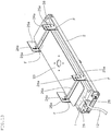
- Fig. 3 is a perspective view showing an outline of the cell culture apparatus according to the present embodiment.
- a culture apparatus 100 is provided with a base 2 having a flat mounting surface 20 for holding the container 1.
- a base 2 having a flat mounting surface 20 for holding the container 1.
- one end on the shorter sides thereof is pivotally supported by a supporting flame 4, and the base 2 can be rotatably moved around the axis.
- the base 2 includes a holding member 21 that forms the mounting surface 20 and the partition plates 30 that are disposed below the holding member 21, and the partition plates 30 are provided with a plurality of rectangular partition pieces 3 that are vertically arranged in parallel at regular intervals.
- a plurality of slits 22 are provided in parallel along the longitudinal direction, and the partition pieces 3 arranged vertically on the partition plates 30 can be respectively protruded from the slits 22. Due to such a configuration, the partition pieces 3 that can be protruded from the mounting surface 20 for a prescribed height are embedded in the base 2.
- Fig. 4 shows an exploded perspective view of the base 2 that is provided in the culture apparatus 100 shown in Fig. 3 .
- two pairs of notched parts 31 are formed on the both side surfaces of the longer sides of the partition plate 30, two pairs of notched parts 31 are formed. These notched parts 31 are obtained by notching the opposing parts of the side surfaces with a prescribed width.
- the partition plate 30 can be positioned below the holding member 21. At this time, the shape, dimension, etc.
- each element is appropriately adjusted such that, in the state where the partition plates 30 are floated from the guide member 32 to allow them to be pressed against the holding member 21, the partition pieces 3 are protruded from the mounting surface 20 for a prescribed height and in the state where the partition plates 30 are supported by the guide member 32, the upper surfaces of the partition pieces 3 are flushed with the mounting surface 20 (see Fig. 6 and Fig. 9 ).
- two supporting members 40 having an L-shaped cross section are rotatably attached with the proximal end of the longer side being pivotably supported.
- the front end on the longer side thereof contacts the lower surface of the partition plate 30, and as a result, the partition plate 30 is lifted up, and supports the partition plate 30 such that it is pressed against the holding member 21 (see Fig. 6 ).
- the supporting member 40 is rotatably moved such that the longer side thereof is inclined relative to the vertical direction by the weight of the shorter side thereof (see Fig. 7 ).
- the partition plate 30 that is no longer supported by the supporting member 40 is lowered to a position at which it is supported by the guide member 32.
- the partition pieces 3 are accommodated into the base 2, whereby the upper end surfaces of the partition pieces 3 are flushed with the mounting surface 20.
- the pressing plate 23 that presses the upper surface of the container 1 held on the mounting surface 20 to pressurize the inside of the container is attached.
- the pressing plate 23 can be attached in such a manner that, in order to allow the pressing plate 23 to move up and down in accordance with the amount of the content in the container 1 (see Fig. 11 and Fig. 12 ), as shown, at each of the four corners of the base 2, an annular rising piece 25 forming an elongated hole-shaped guide hole 24 is vertically provided, and a pin 26 that is horizontally provided in a protruded manner at the four corners of the pressing plate 23 is inserted into the guide hole 24.
- a thinned part 27 that is formed by notching in a groove-shape is formed.
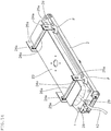
- the mounting surface 20 can be opened by lifting up the pressing plate 23 obliquely.
- holes 11 bored at the four corners of the container 1 are engaged with fixtures 28 provided at the four corners of the base 2, and the tube 12 connected to the container 1 is fixed to a tube-fixing member 29, whereby the container 1 can be attached to the culture apparatus 100.
- the culture medium M is supplied together with the cells C, thereby allowing a prescribed amount of a content liquid to be stored in the container.
- the pressing plate 23 is returned to its initial position to allow it to be pressed against the container 1, and hooks 41 and 42 are engaged with two sides of the shorter sides of the pressing plate 23, whereby the pressing plate 23 can be fixed at a lower position.
- the upper surface of the container 1 held on the mounting surface 20 is pressed by the pressing plate 23, whereby the inside of the container is pressurized.
- Each of the hooks 41 and 42 to be engaged with the pressing plate 23 is pivotably supported by the supporting flame 4 such that it can be rotatably moved.
- engagement with and release from the pressing plate 23 can be conducted.
- the pressing plate 23 after releasing of the hooks 41 and 42 can be moved upward to a higher position at which the pin 26 contacts the upper edge of the guide hole 24.
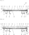
- Figs. 6 to 9 are each an explanatory view for explaining the operation of the cell culture apparatus according to the present embodiment, and the cross sections shown in these figures correspond to cross sections taken along the line A-A in Fig. 3 .
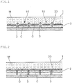
- Fig. 6 shows the initial state of the culture apparatus 100. If the container 1 to which the culture medium M is supplied together with the cells C is attached in this state, by the partition pieces 3 that protrude for a prescribed height from the mounting surface 20, the bottom surface of the container 1 is partitioned into a plurality of the compartments 10 (see Fig. 1 ).
- the container 1 is not shown.
- the amount of the culture medium M to be supplied to the container 1 is adjusted to be an amount that allows the inside of the container to be pressurized when the upper surface of the container 1 is pressed by the pressing plate 23 fixed at a lower position.
- the pressing plate 23 is returned to the initial state from the state shown in Fig. 5 and is pressed against the container 1, and the hooks 41 and 42 are engaged with the two sides of the shorter side of the pressing plate 23.
- the inside of the container can be pressurized by pressing by means of the pressing plate 23 the upper surface of the container 1 held on the mounting surface 20.
- the curing culture step is conducted in the way mentioned above. After the curing culture step proceeds and the density of the cells C that have been proliferated is increased to a level that is equal to or higher than a prescribed level and exceeds a range that is suited to culture, the curing culture step is shifted to an expansion culture step.
- the push-up member 5 moves upward, and the base 2 pivotably supported by the supporting flame 4 is moved upward rotatably around the axis.
- the supporting member 40 that supports the partition plate 30 and has an L-shaped cross section, contact with the partition plate 30 is released, and is rotatably moved by the weight of the shorter side such that the longer side is inclined relative to the vertical direction.
- the partition plate 30 that is no longer supported by the supporting member 40 is lowered to a position at which it is supported by the guide member 32, and along with this, the partition pieces 3 are accommodated into the base 2, and the upper end surfaces of the partition pieces 3 are flushed with the mounting surface 20.
- the compartments 10 formed by division by the partition pieces 3 are removed, and the inside of the container becomes one compartment, whereby the culture area is expanded (see Fig. 2 ).
- the hooks 41 and 42 are engaged with the two sides of the shorter sides of the pressing plate 23.
- engagement of the hooks 41 and 42 can be released.
- the base 2 is rotatably moved upward by allowing the push-up member 5 that has moved upward to contact a contact member 50 provided on the shorter side opposite to the side on which the rotation axis of the base 2 is provided.
- a beam-like contact piece 51 is bridged over the contact member 50.
- the push-up member 5 After allowing the base 2 to move rotatably by a predetermined angle, the push-up member 5 is moved downward. As a result, as shown in Fig. 9 , the base 2 is rotatably moved downward and returns to the initial position. At this time, vibration is transmitted to the container 1 held on the mounting surface 20 of the base 2 by the impact generated by receiving of the base 2 by the supporting frame 4. Due to such a configuration, by repeating the rotating operation of the base 2 by moving the push-up member 5 up and down, an operation in which after allowing the container 1 to be moved to a position higher than the initial position, returning the container 1 to the initial position and applying vibration to the container 1 that has returned to the initial position are repeated, whereby the content liquid of the container 1 can be stirred.
- a driving mechanism for moving the push-up member 5 up and down can be configured as a cam mechanism includes a plate cam 5b having a first cam surface 5c with an arcuate contour and a second cam surface 5d with a linear contour, and a receiving plate 5a provided horizontally at the base end of the push-up member 5 as a follower.
- the configuration of the driving mechanism is not limited thereto.
- the curvature of the cam surfaces 5c and 5d, the position of a drive shaft 5e for rotating the plate cam 5b, and the rotational speed of the drive shaft 5e are appropriately set so that the push-up member 5 moves upward as the first cam surface 5c pushes up a receiving plate 5a (see Figs. 10(a) to 10(e) ), the plate cam 5b leaves from the receiving plate 5a when switching to the second cam surface 5d, and then the push-up member 5 falls down (see Figs. 10(f) to 10(h) ), whereby the up-and-down movement of the push-up member 5 is repeated as the plate cam 5b rotates in a fixed direction.
- the driving mechanism is configured as described above, when the base 2 rotates downward to return to its initial position, the base 2 rotatably moves as if it falls down, so that an impact is generated when the supporting frame 4 receives the base 2.
- the culture medium M is additionally supplied to the container 1.
- the pressing plate 23 is pushed up by the container 1 of which the amount of the content is increased to have an increased thickness.
- the pin 26 projecting from the pressing plate 23 reaches the upper edge of the guide hole 24, the pressing plate 23 cannot move upward anymore and is fixed at the upper position (see Fig. 12 ).
- the culture apparatus 100 can be shifted from the curing culture step to the expansion culture step by the rotational operation of the base 2.
- the bottom surface of the container 1 that becomes flat by being flattened by the weight of the content liquid is used as a culture surface. If the bottom surface of the container 1 is not sufficiently flattened, wrinkles or slacks are generated on the culture surface, and cells are accumulated in that portion, resulting in excessive cell density. Further, since movement of cells is restricted, it may be concerned that proliferation efficiency of cells is lowered.
- such a place where cells are accumulated may cause cells to remain in the container when recovering cultured cells.
- Patent Document 4 a method is taken in which holes are bored at the four corners of the culture container and fixtures are provided vertically at the four corners of the container mounting table, and the holes of the culture container are engaged with the fixtures of the container mounting table and the culture container is pulled, the culture surface is flattened.
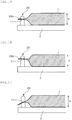
- Fig. 17 shows an example in which the hole 11 provided in the container 1 is engaged with the fixture 28 to pull the container 1. This method is still insufficient to avoid generation of wrinkles or slacks on the bottom surface of the container 1.
- the arrangement and number of the fixtures 28 are not particularly limited, and it suffices that two or more fixtures 28 be oppositely arranged on the periphery of the base 2.
- the fixture 28 be provided vertically at the four corners of the base 2, and that in the case of using a container 1 having a relatively large size, a larger number of fixtures 28 be provided vertically.
- the fixture 28 can be arranged such that one fixture is disposed in the middle of the end part of each of the shorter sides of the base 2, or alternatively, one fixture is disposed in the middle of the end part of one of the shorter sides and two or more fixtures are disposed at the opposing end parts of one of the short sides.
- the hole 11 bored in the container 1 can be provided in accordance with the arrangement and number of the fixture 28 provided in the base 2, and in order to allow the peripheral part of the hole 11 to be engaged with the recess 28a by inserting the fixture 28 into the hole 11, the hole 11 can be provided at a heat-sealed end part region, etc. That is, it suffices that two or more holes 11 be provided at the end part of the container 1 in correspondence with two or more fixtures 28 provided at the peripheral part of the base 2. At this time, it is needless to say that sealing property of the container 1 is required to be prevented from being lowered by provision of the holes 11 in the container 1.
- the shape of the fixture 28 is not particularly limited. For example, it may be substantially columnar, but other shapes such as a substantially rectangular parallelepiped shape may be used. Further, the upper part of the recess 28a may be formed in a dome shape, and the lower part of the recess 28a may be formed into a columnar shape or a prismatic shape.
- the recess 28a be formed circumferentially with respect to the horizontal plane in the fixture 28, but the manner of formation is not limited thereto, and it may be formed in a semi-circumferential shape, an arc shape or the like with respect to the horizontal plane in the outer direction of the base 2. Further, the horizontal cross section of the recess 28a is not limited to a circular shape, and it may be a polygonal shape, a star shape, or the like.
- the position where the recess 28a is formed in the fixture 28 is determined based on the thickness of the container 1 that becomes full by filling the culture solution in the culture container 1 to a full capacity thereof taking into consideration the thickness of the container 1 at the time of being full.
- Fig. 15 shows a state in which, in the fixture 28, the recess 28a is formed at a position, upward from the surface of the base 2, 1/2 of the thickness of the container 1 which is full (almost 1/2 of the liquid depth d), and the peripheral edge portion of the hole 11 of the container 1 is engaged with the recess 28a.
- the end part of the container 1 is held at the height of the recess 28a, and the container 1 can be fixed to the base 2 with the bottom surface of the container 1 being flattened.
- Fig. 16 shows a state in which, in the fixture 28, the recess 28a is formed at a position, upward from the surface of the base 2, 3/4 of the thickness of the container 1 which is full (almost 3/4 of the liquid depth d) and the peripheral edge portion of the hole 11 of the container 1 is engaged with the recess 28a.
- the bottom surface of the container 1 can be flattened.
- the recess 28a is at a position upward from the surface of the base 2 that is slightly higher than the thickness of the container 1 that is full.
- a position where the recess 28a is formed in the fixture 28 be set, upward from the surface of the base 2, such that it corresponds to 1/2 to 3/2, more preferably 1/2 to 1, further preferably 1/2 to 3/4, of the thickness of the container 1 which is full.
- the bottom surface of the container 1 after the culture step is shifted to the expansion culture step can be kept in a flattened state more reliably, and the culture surface can be in a state where no wrinkles or slacks are formed. As a result, the culture area of the container 1 can be maximized.
- the bottom surface of the container 1 is partially raised and separated into plural compartments 10 by holding the container 1 on the base 2 in which the partition pieces 3 that can be protruded from the mounting surface 20 for a prescribed height are embedded in a state that the partition pieces 3 are protruded.
- the cell culture method according to the present invention can be implemented without being limited thereto.
- a plurality of rod-like members may be arranged side by side on the mounting surface 20, and the container 1 is held thereon.
- the bottom surface of the container 1 is partially raised by pushing up by the rod-like member, and as a result, the bottom surface is separated into plural compartments 10. If such rod-like members are drawn, the bottom surface of the container 1 is flattened by the weight of the content liquid, whereby the culture area of the container is expanded.
- the pressing plate 23 is attached by providing vertically annular rising sections 25 forming an elongated hole-shaped guide hole 24 at the four sides of the base 2, and inserting the pin 26 that is horizontally projected at the four corners of the pressing plate 23.
- the manner of attachment of the pressing plate 23 is not limited thereto. It suffices that the pressing plate 23 be attached such that it can be moved vertically in accordance with the amount of the content of the container 1. For example, it can be attached as shown in Fig. 13 and Fig. 14 .
- Fig. 13 and Fig. 14 two pairs of rising sections 25a having elongated hole-shaped guide holes 24a are provided vertically at opposing positions on the longer sides of the base 2 so as to form a pair, and the pressing plate 23 is attached so that it can be moved up and down through a supporting rod 26a disposed between each of the rising sections 25a forming a pair.
- the hook F is engaged with the supporting rod 26a inserted into the guide hole 24a to suppress the upward movement of the pressing plate 23, whereby the upper surface of the container 1 in which a content is filled in a prescribed amount is pressed by the pressing plate 23 fixed at a lower position, thus enabling the inside of the container to be pressurized (see Fig. 13 ).
- the pressing plate 23 In the expansion culture step, by releasing the engagement of the hook F, the pressing plate 23 can be moved upward. When the supporting rod 26a reaches the upper edge of the guide hole 24a, the pressing plate 23 cannot be moved to a position higher than the upper edge, and fixed at an upper position. Due to such a configuration, the upper surface of the container 1 of which the content amount is increased to have an increased thickness by additional supply of a culture medium M is pressed by the pressing plate 23, thus enabling the inside of the container to be pressurized (see Fig. 14 ).
- the hook F is allowed to move rotatably by its own weight by the inclination of the base 2.
- the present invention can be preferably used in gene therapy, immunotherapy, regenerative therapy, production of antibody medicines, etc. where cells are cultured aseptically and easily in a closed system by using a cell culture apparatus.
Landscapes
- Health & Medical Sciences (AREA)
- Engineering & Computer Science (AREA)
- Life Sciences & Earth Sciences (AREA)
- Chemical & Material Sciences (AREA)
- Organic Chemistry (AREA)
- Bioinformatics & Cheminformatics (AREA)
- Wood Science & Technology (AREA)
- Zoology (AREA)
- Biomedical Technology (AREA)
- Biotechnology (AREA)
- Genetics & Genomics (AREA)
- General Health & Medical Sciences (AREA)
- General Engineering & Computer Science (AREA)
- Microbiology (AREA)
- Biochemistry (AREA)
- Sustainable Development (AREA)
- Cell Biology (AREA)
- Clinical Laboratory Science (AREA)
- Immunology (AREA)
- Hematology (AREA)
- Developmental Biology & Embryology (AREA)
- Medicinal Chemistry (AREA)
- Virology (AREA)
- Tropical Medicine & Parasitology (AREA)
- Rheumatology (AREA)
- Dermatology (AREA)
- Transplantation (AREA)
- Mechanical Engineering (AREA)
- Apparatus Associated With Microorganisms And Enzymes (AREA)
Abstract
Description
- The present invention relates to a cell culture method for culturing cells under an artificial environment and a cell culture apparatus.
- In recent years, in the field of production of medicines, gene therapy, regenerative therapy, immunotherapy and the like, it is required to culture cells, tissues, microorganisms, viruses, etc. (these are collectively referred to as "cells") efficiently in a large amount in an artificial environment. In such cell culture, as the cell density in a culture solution (hereinafter the culture solution means one including cells and a culture medium) increases, depletion of culture medium components necessary for proliferation, and accumulation of metabolic products of the cells themselves occur, the proliferation rate decreases and the cell density reaches saturation. Therefore, when cells are cultured in a relatively large amount, culture is usually carried out while repeating subculture so that the cell density is maintained properly.
- At the time of subculture, there may be cases where cells are transferred from a well plate to a flask, etc. For example, using cell culture well plates, cells are added to individual wells together with a culture medium so as to attain a proper cell density, and culture is started. After sufficiently proliferating the cells in the wells, the proliferated cells are transferred to a cell culture flask. In accordance with the progress of cell proliferation, a culture medium is added to conduct culture and also conduct subculture. When the cells are proliferated to a prescribed level, the cells are transferred to a flask or a bag having a larger capacity, and culture, supplement of a culture medium, and subculture are repeated, whereby the cells are cultured in a large amount (see paragraph [0027], etc. of Patent Document 1).
- Also, a method as following is adopted when using cryopreserved cells. After thawing, culture is conducted for several days in a high density state using a well plate in order to restore the original functions of the cells (hereinafter referred to as "curing culture"), and after restoring the function of the cells to their original state, the cells are transferred to a flask and cultured (hereinafter referred to as "expansion culture"), followed by activation culture in which antibody stimulation is performed is conducted (see paragraph [0057], etc. of Patent Document 2).
- In such cell culture, equipment such as a well plate or a flask has been conventionally used, but in recent years, in place of these equipment, a culture bag made of a flexible material such as a resin film has come to be used (see
Patent Documents 3 and 4). Equipment such as a well plate and a flask is not suited to culture a large amount of cells. On the contrary, in the case of using a culture bag, not only the cells can be cultured in a large amount since the capacity of the bag can be increased easily, but also cell culture can be conducted in a closed system, and hence, it has a merit that risk of contamination by fungi or virus during culture can be reduced. Therefore, when the cells are cultured in a large amount on a relatively large scale (i.e. larger than the laboratory scale), a culture bag is preferably used. -
- Patent Document 1:
JP-A-2011-241159 - Patent Document 2:
JP-A-2013-215141 - Patent Document 3:
WO2012/032761 - Patent Document 4:
WO2008/136371 - However, in such cell culture, it is necessary to repeat pipetting operation many times when transferring the cells from a well plate to a flask, and every time subculture is conducted, the cells are required to be transferred to a new culture container such as a flask and a bag, not only an operation becomes complicated, but also the cells may be damaged. Further, there is a high risk of contamination.
- The present invention has been attained taking the above-mentioned circumstances into consideration, and an object thereof is to provide a cell culture method and a cell culture apparatus capable of maintaining the cell density at the time of culture at an appropriate level, and also capable of eliminating the need of a task of transfer of cells from one culture container to another when proliferating a large amount of cells, thereby to reduce damage on cells and lower risk of contamination.
- The cell culture method according to the present invention is a method of culturing cells in which a culture medium is supplied together with cells to a container formed of a flexible material, thereby to conduct cell culture, wherein,
a bottom surface of the container is partially raised to be partitioned into a plurality of compartments,
the cells are cultured in each compartment, and
in due time, the compartments are removed to expand a culture area in the container. - Further, the cell culture apparatus according to the present invention is a cell culture apparatus for conducting cell culture in which a culture medium is supplied together with cells to a container formed of a flexible material, wherein,
a base having a flat mounting surface that holds the container is provided,
partition pieces that can be protruded from the mounting surface for a prescribed height are embedded in the base, and
when the partition pieces are accommodated into the base, upper end surfaces of the partition pieces are flushed with the mounting surface. - According to the present invention, while culturing cells in a state where the cell density is increased, by expanding the culture area in the container when the density of proliferated cells is increased to a level exceeding a level suited to culture, it becomes possible to proliferate cells efficiently while maintaining the cell density at an appropriate level without conducting subculture.
- Further, since transfer of cells from one culture container to another is not necessary, and a culture solution is retained in the same culture container, reduction of damage on cells and reduction of risk of contamination become possible.
-
-
Fig. 1 is an explanatory view showing an outline of the curing culture step in the cell culture method according to the embodiment of the present invention; -
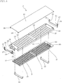
Fig. 2 is an explanatory view showing an outline of the expansion culture step in the cell culture method according to the embodiment of the present invention; -
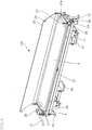
Fig. 3 is a perspective view showing an outline of the cell culture apparatus according to the embodiment of the present invention; -
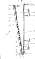
Fig. 4 is an exploded perspective view of a base provided in the cell culture apparatus shown inFig. 3 ; -
Fig. 5 is a perspective view showing a state in which a mounting surface of the cell culture apparatus shown inFig. 3 is open; -
Fig. 6 is an explanatory view for explaining the operation of the cell culture apparatus shown inFig. 3 ; -
Fig. 7 is an explanatory view for explaining the operation of the cell culture apparatus shown inFig. 3 ; -
Fig. 8 is an explanatory view for explaining the operation of the cell culture apparatus shown inFig. 3 ; -
Fig. 9 is an explanatory view for explaining the operation of the cell culture apparatus shown inFig. 3 ; -
Fig. 10 is an explanatory view showing one example of a driving mechanism that moves up and down a push-up member that rotates a base provided in the cell culture apparatus shown inFig. 3 ; -
Fig. 11 is an explanatory view showing a state in which a curing culture step is conducted by using the cell culture apparatus shown inFig. 3 ; -
Fig. 12 is an explanatory view showing a state in which an expansion culture step is conducted by using the cell culture apparatus shown inFig. 3 ; -
Fig. 13 is a perspective view showing an outline of a modification example of the cell culture apparatus according to the embodiment of the present invention; -
Fig. 14 is a perspective view showing an outline of a modification example of the cell culture apparatus according to the embodiment of the present invention; -
Fig. 15 is an explanatory view showing one example in which a hole formed in the container is engaged with a recess formed in a fixture; -
Fig. 16 is an explanatory view showing another example in which a hole formed in the container is engaged with a recess formed in a fixture; and -
Fig. 17 is an explanatory view showing a state in which a hole formed in the container is engaged with a fixture. - Hereinbelow, preferred embodiments of the present invention will be explained with reference to the drawings.
- First, the cell culture method according to the present embodiment will be explained.
- The cell culture method according to the present embodiment is a cell culture method in which cells to be cultured (cultured cells) C and a culture medium M to culture these cells C are supplied to a
container 1 formed of a flexible material, thereby to conduct cell culture. In particular, the cell culture method is suitable for culturing damaged cells, such as cells that have been sampled from a patient or cells that have been frozen, while curing them and recovering the functions inherent to them. - In the present embodiment, the
container 1 is formed of a flexible material and formed into a bag-like shape. The shape is normally rectangular in many cases. For example, it may be a bag of which the four sides are sealed by heat sealing, or may be an integrally-shaped bag obtained by blow molding. - The
container 1 may be in a square shape, an elliptical shape, a circular shape, or the like, and may have various shapes according to need. - Further, it is preferred that the
container 1 be capable of conducting cell culture in a closed system (sealed system) and have permeability to oxygen and carbon dioxide that is required when the container is used in a CO2 incubator. In particular, it is preferred that thecontainer 1 be suited to be used under culture environment of 37°C and 5% carbon dioxide concentration. - Further, it is preferred that part or all of the
container 1 have transparency such that the progress situation of cell culture, the state of cells, etc. can be confirmed, and that thecontainer 1 have low cell toxicity, low elution properties, and suitability to radiation sterilization. - As the specific examples of the material of the
container 1 that satisfies such conditions, a polyethylene-based resin such as polyethylene, a copolymer of ethylene and α-olefin, a copolymer of ethylene and vinyl acetate, an ionomer obtained by using a copolymer of ethylene and acrylic acid or methacrylic acid and a metal ion, or the like can be given. Further, polyolefin, a styrene-based elastomer, a polyester-based thermoplastic elastomer, a silicone-based thermoplastic elastomer, a silicone resin or the like can also be used. - In the example shown in
Fig. 5 , atube 12 is connected to one side of the shorter sides of thecontainer 1 that has a rectangular shape. Through thistube 12, cells or a culture medium are supplied from the outside to thecontainer 1, and after the step in thecontainer 1 is completed, the cells or the culture medium are collected from thecontainer 1. Two tubes may be connected, i.e. one is used for supply and the other is used for collection. In addition to these tubes, a tube for taking out a sample or other tubes may be connected. - Although not particularly shown, the
tube 12 may be connected to a tubular port attached to thecontainer 1. In order to reduce the amount of a remaining liquid when cells or a culture medium are collected from thecontainer 1, thecontainer 1 may be configured such that the accommodation part thereof has a shape that becomes gradually narrow toward the port. - The material of the
tube 12 connected to thecontainer 1 may be appropriately selected according to the environment of use. When the container is used in a CO2 incubator, it is desirable to use one having excellent gas permeability for oxygen and carbon dioxide. When the container is used outside a CO2 incubator, it is desirable to use one having gas barrier properties. - Specifically, silicone rubber, soft vinyl chloride resins, polybutadiene resins, ethylene-vinyl acetate copolymers, chlorinated polyethylene resins, polyurethane-based thermoplastic elastomers, polyester-based thermoplastic elastomers, silicone-based thermoplastic elastomers, styrene-based elastomers or the like can be used. As the styrene-based elastomer, SBS (styrene-butadiene-styrene), SIS (styrene-isoprene-styrene), SEBS (styrene-ethylene-butylene-styrene), SEPS (styrene-ethylene-propylene-styrene) or the like can be used.
- The cell culture method according to the present embodiment cultures, using
such container 1, the cells that have suffered damage and whose functions have declined, such as cells that have been sampled from a patient or cells that have been thawed after frozen storage. Also it comprises a curing culture step in which such damaged cells are cultured while curing at the initial stage of cell culture in order to recover the functions inherent to the cells, and an expansion culture step in which, after curing of the cells proceeds to some extent, the culture area in the container is expanded and culture of cells is continued until a prescribed cell density is attained. - In the present embodiment, in the curing culture step, as shown in
Fig. 1 , thecontainer 1 in which the culture medium M is supplied together with the cells C is held on abase 2 having a flat mountingsurface 20. The bottom surface of thecontainer 1 is partially raised bypartition pieces 3 that protrude from the mountingsurface 20 for a prescribed height, thereby to partition it into a plurality ofcompartments 10. The cells C are cultured in eachcompartment 10. At this time, in the bottom surface of thecontainer 1, parts deformed by pushing up of thepartition pieces 3 are raised from the mountingsurface 20 as if they float up, and the remaining flat parts that contact the mountingsurface 20 serve as a culture surface. - As a result, when cells C are supplied to the
container 1 in a state that they are suspended in the culture medium M, thereafter, irrespective of being floating cells or anchorage-dependent cells, the cells C are settled to the bottom surface of thecontainer 1. Due to collecting of the settled cells C on the culture surface of eachcompartment 10, the cells C can be cultured at a high cell density. - As described above, in the curing culture step, the cells C are collected on the culture surface of each
compartment 10, and cell culture is conducted. By adjusting the number, interval, size, etc. of thecompartments 10 formed on the bottom surface of thecontainer 1, it is possible to adjust the density of the cells C collected on the culture surface of eachcompartment 10 to an appropriate range. - It is preferred that the area of the culture surface in each
compartment 10 be almost the same as the bottom surface area of each well of a well plate (e.g. 24-well plate, etc.) that has been conventionally used for subculture in accordance with the type or inoculation concentration of cells C to be cultured. - When conducting a curing culture step in the manner mentioned above, the
partition piece 3 that partitions the bottom part of thecontainer 1 is formed in a rectangular shape with a prescribed thickness. The thickness or the protrusion height from the mountingsurface 20 are appropriately set in order to prevent cells during culture from moving across the compartments. For example, the thickness of thepartition piece 3 is preferably 0.5 to 2.0 mm, and the protrusion height from the mountingsurface 20 is preferably 0.5 to 1.5 mm. - Subsequently, in the curing culture step, the cells C are cultured in each
compartment 10 formed on the bottom surface of thecontainer 1 in a state where the cell density is increased, and after the density of the proliferated cells C (the number of cells per unit area of the culture surface of each compartment 10) is increased to a level equal to or higher than a prescribed level, the curing culture step shifts to the expansion culture step. - In the expansion culture step, as shown in
Fig. 2 , thepartition pieces 3 are accommodated into thebase 2, and the upper end surfaces of thepartition pieces 3 are flushed with the mountingsurface 20, thereby to remove thecompartments 10, and to allow thecontainer 1 to be used as one compartment. As a result, the culture area is expanded. - That is, as mentioned above, in the curing culture step, on the bottom surface of the
container 1, parts that are deformed by pushing up of thepartition pieces 3 are raised as if they float up from the mountingsurface 20, whereby the bottom surface is partitioned intoplural compartments 10. By accommodating thepartition pieces 3 into thebase 2 and allowing the upper surfaces thereof to be flushed with the mountingsurface 20 to remove thecompartments 10, the parts are flattened by the weight of the content liquid and can be used as a culture surface, and as a result, the culture area is expanded in an amount corresponding to the amount of the flattened parts. - As mentioned above, in the present embodiment, the cells C are cultured while curing in the curing culture step in a state where the cell density is increased. When the density of the proliferated cells C is increased to a level equal to or higher than a certain level and exceeds a range that is suited to culture, the curing culture step shifts to the expansion culture step, whereby the culture area in the container is expanded, and culture of cells C is continued until a prescribed cell density is attained. When continuing cell culture by expanding the culture area in the container, a culture medium M is additionally supplied to the
container 1 according to need. - When shifting to the expansion culture step, it is preferred that the content liquid in the
container 1 be stirred. For example, after moving thecontainer 1 to a position higher than the initial position, thecontainer 1 is returned to the initial position, and vibration is applied to thecontainer 1 that is returned to the initial position. By repeating this operation, the content liquid in thecontainer 1 can be stirred. - By doing so, in addition to the stirring of the content liquid by the up-and-down movement of the
container 1, the cells C are diffused as if they fly up in the content liquid by vibration applied to thecontainer 1. As a result, not only the content liquid in thecontainer 1 is stirred efficiently in the up-and-down direction, the distribution of the cells C in the content liquid or the concentration of the culture medium M in thecontainer 1 can be uniform to maintain good culture environment, but also adhesion to the inner wall of the container or excessive aggregation of the cells C can be suppressed, whereby proliferation of the cells C can be promoted. Further, when the cells C to be cultured are adherent cells, by vibration applied to thecontainer 1, it is possible to promote peeling of the cells C from the culture surface of thecontainer 1. - By the cell culture method according to the present embodiment, not only the cells C can be proliferated efficiently while maintaining the cell density at the time of culture at an appropriate level without conducting subculture, but also transfer of cells from one culture container to another culture container becomes unnecessary. Due to retention of the culture solution in the same culture container, damage on the cells C and risk of contamination can be reduced.
- Therefore, in the case of culturing floating cells such as lymphocytes, for example, by applying the present embodiment, the cells C are collected in each
compartment 10 formed on the bottom surface of thecontainer 1, the concentration of activator substances such as cytokine generated by the cells C is locally increased, and the interaction between the cells occurs, whereby culture can be conducted with an increased cell activity. Subsequently, by expanding the culture area in the container after the cells C are proliferated to some extent, the cells C can be cultured efficiently in the same container while maintaining an appropriate cell density. Therefore, the present embodiment is suitable in particular for culturing efficiently the cells that have suffered damage and whose functions have declined such as cells that just have been sampled from a patient or cells that have just been thawed after frozen storage efficiently, while curing them and recovering the functions inherent to them. - When culturing anchorage-dependent cells such as skin cells, iPS cells, mesenchymal stem cells, for example, by applying the present embodiment, the cells C are adhered to the culture surface of each
compartment 10 formed on the bottom surface of thecontainer 1, and proliferated. After that, by removing thecompartments 10 to expand the culture area in the container, the culture surface on which the cells C can be proliferated can be expanded with an appropriate arrangement. Therefore, an operation such as subculture, i.e. an operation of collecting cells by peeling them from the culture surface and inoculation of cells to a new culture container, which is an operation that is complicated and has a risk of lowering proliferation efficiency, becomes unnecessary, whereby cell culture can be conducted in the same container under similar culture environment to that of subculture. - In the meantime, the
container 1 used in the present embodiment is easily deformed since it is formed of a flexible material, and hence, the shape is not stable. Therefore, during the culture period that requires several days in general, if thecontainer 1 is deformed by application of vibration, etc., the content liquid excessively flows to damage the cells, thus lowering the culture efficiency. Taking such circumstances into consideration, in the present embodiment, when cell culture is conducted by supplying the culture medium M together with the cells C to theculture container 1 formed of a flexible material, it is preferred that cell culture be conducted in a state that the inside of the container is pressurized so that thecontainer 1 is not easily deformed when vibration is applied during a long-term culture period and flow of the content liquid that damages the cells C during culture is suppressed, thereby enabling efficient proliferation of the cells C. This will be explained later. - Subsequently, an explanation will be made on the cell culture apparatus according to the present embodiment that is preferable to be used in the cell culture method mentioned above.
-
Fig. 3 is a perspective view showing an outline of the cell culture apparatus according to the present embodiment. - In the present embodiment, a
culture apparatus 100 is provided with abase 2 having a flat mountingsurface 20 for holding thecontainer 1. Insuch base 2, one end on the shorter sides thereof is pivotally supported by a supportingflame 4, and thebase 2 can be rotatably moved around the axis. - In addition, the
base 2 includes a holdingmember 21 that forms the mountingsurface 20 and thepartition plates 30 that are disposed below the holdingmember 21, and thepartition plates 30 are provided with a plurality ofrectangular partition pieces 3 that are vertically arranged in parallel at regular intervals. On the mountingsurface 20 of the holdingmember 21, a plurality ofslits 22 are provided in parallel along the longitudinal direction, and thepartition pieces 3 arranged vertically on thepartition plates 30 can be respectively protruded from theslits 22. Due to such a configuration, thepartition pieces 3 that can be protruded from the mountingsurface 20 for a prescribed height are embedded in thebase 2. - Here,
Fig. 4 shows an exploded perspective view of thebase 2 that is provided in theculture apparatus 100 shown inFig. 3 . In the present embodiment, on the both side surfaces of the longer sides of thepartition plate 30, two pairs of notchedparts 31 are formed. These notchedparts 31 are obtained by notching the opposing parts of the side surfaces with a prescribed width. By fitting aguide member 32 to the holdingmember 21 in a state where the twoguide members 32 are loosely fitted to these notchedparts 31, thepartition plate 30 can be positioned below the holdingmember 21. At this time, the shape, dimension, etc. of each element is appropriately adjusted such that, in the state where thepartition plates 30 are floated from theguide member 32 to allow them to be pressed against the holdingmember 21, thepartition pieces 3 are protruded from the mountingsurface 20 for a prescribed height and in the state where thepartition plates 30 are supported by theguide member 32, the upper surfaces of thepartition pieces 3 are flushed with the mounting surface 20 (seeFig. 6 andFig. 9 ). - On the other hand, to the supporting
flame 4 that pivotally supports thebase 2, two supportingmembers 40 having an L-shaped cross section are rotatably attached with the proximal end of the longer side being pivotably supported. In such supportingmember 40, when the longer side is in parallel with the vertical direction, the front end on the longer side thereof contacts the lower surface of thepartition plate 30, and as a result, thepartition plate 30 is lifted up, and supports thepartition plate 30 such that it is pressed against the holding member 21 (seeFig. 6 ). When the contact with thepartition plate 30 is released, the supportingmember 40 is rotatably moved such that the longer side thereof is inclined relative to the vertical direction by the weight of the shorter side thereof (seeFig. 7 ). Thepartition plate 30 that is no longer supported by the supportingmember 40 is lowered to a position at which it is supported by theguide member 32. As a result, thepartition pieces 3 are accommodated into thebase 2, whereby the upper end surfaces of thepartition pieces 3 are flushed with the mountingsurface 20. - Further, to the
base 2, thepressing plate 23 that presses the upper surface of thecontainer 1 held on the mountingsurface 20 to pressurize the inside of the container is attached. Thepressing plate 23 can be attached in such a manner that, in order to allow thepressing plate 23 to move up and down in accordance with the amount of the content in the container 1 (seeFig. 11 and Fig. 12 ), as shown, at each of the four corners of thebase 2, an annular risingpiece 25 forming an elongated hole-shapedguide hole 24 is vertically provided, and apin 26 that is horizontally provided in a protruded manner at the four corners of thepressing plate 23 is inserted into theguide hole 24. - Further, in the shown example, among the four annular rising
pieces 25 provided in thebase 2, at the upper end side of the two annular risingpieces 25 positioned at the both ends on one of the longer sides of thebase 2, a thinnedpart 27 that is formed by notching in a groove-shape is formed. Thereby, when a force is applied in a state where thepin 26 that is inserted into theguide hole 24 of the annular risingpiece 25 contacts the upper edge of theguide hole 24 when thepressing plate 23 is lifted up, thepin 26 is removed from theguide hole 24 through the thinnedpart 27. - Due to such a configuration, as shown in
Fig. 5 , the mountingsurface 20 can be opened by lifting up thepressing plate 23 obliquely. In this state, holes 11 bored at the four corners of thecontainer 1 are engaged withfixtures 28 provided at the four corners of thebase 2, and thetube 12 connected to thecontainer 1 is fixed to a tube-fixingmember 29, whereby thecontainer 1 can be attached to theculture apparatus 100. - When attaching the
container 1 to theculture apparatus 100, to thecontainer 1, the culture medium M is supplied together with the cells C, thereby allowing a prescribed amount of a content liquid to be stored in the container. Then, after attaching thecontainer 1 to theculture apparatus 100, thepressing plate 23 is returned to its initial position to allow it to be pressed against thecontainer 1, and hooks 41 and 42 are engaged with two sides of the shorter sides of thepressing plate 23, whereby thepressing plate 23 can be fixed at a lower position. As a result, the upper surface of thecontainer 1 held on the mountingsurface 20 is pressed by thepressing plate 23, whereby the inside of the container is pressurized. - Each of the
hooks pressing plate 23 is pivotably supported by the supportingflame 4 such that it can be rotatably moved. By moving thehooks pressing plate 23 can be conducted. Thepressing plate 23 after releasing of thehooks pin 26 contacts the upper edge of theguide hole 24. - Subsequently, the operation of the
culture apparatus 100 will be explained. -
Figs. 6 to 9 are each an explanatory view for explaining the operation of the cell culture apparatus according to the present embodiment, and the cross sections shown in these figures correspond to cross sections taken along the line A-A inFig. 3 . -
Fig. 6 shows the initial state of theculture apparatus 100. If thecontainer 1 to which the culture medium M is supplied together with the cells C is attached in this state, by thepartition pieces 3 that protrude for a prescribed height from the mountingsurface 20, the bottom surface of thecontainer 1 is partitioned into a plurality of the compartments 10 (seeFig. 1 ). - As a result, the curing culture step of the cell culture method mentioned above is ready to start.
- In
Figs. 6 to 9 , thecontainer 1 is not shown. In the curing culture step, as shown inFig. 11 , the amount of the culture medium M to be supplied to thecontainer 1 is adjusted to be an amount that allows the inside of the container to be pressurized when the upper surface of thecontainer 1 is pressed by thepressing plate 23 fixed at a lower position. - Due to such a configuration, after attaching the
container 1 to theculture apparatus 100, thepressing plate 23 is returned to the initial state from the state shown inFig. 5 and is pressed against thecontainer 1, and thehooks pressing plate 23. As a result, the inside of the container can be pressurized by pressing by means of thepressing plate 23 the upper surface of thecontainer 1 held on the mountingsurface 20. - By allowing the inside of the container to be in a pressurized state, excessive flow of the content liquid in the container can be suppressed, so that damage on the cells C during culture can be prevented. Furthermore, if the gas dissolved in the culture medium M evaporates and the bubbles retain in the container, there may be disadvantages that minute bubbles refract the optical path of the illumination when observing the interior of the container, which makes it impossible to observe cells clearly, and that when a gas such as oxygen diffuses from the outside into the culture solution in the container, a gas transfers a boundary of two locations, i.e. the gas and the film and the film and the culture solution, however, due to the retention of bubbles in the container, a gas transfers a boundary of three locations, i.e. the gas and the film, the film and the bubbles, and the bubbles and the culture solution, whereby gas diffusion to the culture solution in the container is lowered. By pressurizing the inside of the container, it is possible to suppress evaporation of a gas dissolved in the culture medium M, whereby the above-mentioned disadvantages can be prevented from occurring.
- In the above-mentioned cell culture method, the curing culture step is conducted in the way mentioned above. After the curing culture step proceeds and the density of the cells C that have been proliferated is increased to a level that is equal to or higher than a prescribed level and exceeds a range that is suited to culture, the curing culture step is shifted to an expansion culture step.
- In the present embodiment, when shifting to the expansion culture step, the push-up
member 5 moves upward, and thebase 2 pivotably supported by the supportingflame 4 is moved upward rotatably around the axis. As a result, as shown inFig. 7 , as for the supportingmember 40 that supports thepartition plate 30 and has an L-shaped cross section, contact with thepartition plate 30 is released, and is rotatably moved by the weight of the shorter side such that the longer side is inclined relative to the vertical direction. Thepartition plate 30 that is no longer supported by the supportingmember 40 is lowered to a position at which it is supported by theguide member 32, and along with this, thepartition pieces 3 are accommodated into thebase 2, and the upper end surfaces of thepartition pieces 3 are flushed with the mountingsurface 20. As a result, thecompartments 10 formed by division by thepartition pieces 3 are removed, and the inside of the container becomes one compartment, whereby the culture area is expanded (seeFig. 2 ). - Further, in the initial state, the
hooks pressing plate 23. By rotatably moving thebase 2 upward, engagement of thehooks - That is, in the present embodiment, the
base 2 is rotatably moved upward by allowing the push-upmember 5 that has moved upward to contact acontact member 50 provided on the shorter side opposite to the side on which the rotation axis of thebase 2 is provided. A beam-like contact piece 51 is bridged over thecontact member 50. Then, when the push-upmember 5 contacts thecontact member 50 to allow thebase 2 to move upward rotatably, as shown inFig. 7 , thecontact piece 51 contacts alower tongue piece 41 a of thehook 41, that is one of the hooks, then thehook 41 is rotatably moved so that the engagement is released. Then, when thebase 2 is further rotatably moved upward, as shown inFig. 8 , theother hook 42 is rotatably moved so as to be pushed by thebase 2, and the engagement with thehook 42 is also released. - After allowing the
base 2 to move rotatably by a predetermined angle, the push-upmember 5 is moved downward. As a result, as shown inFig. 9 , thebase 2 is rotatably moved downward and returns to the initial position. At this time, vibration is transmitted to thecontainer 1 held on the mountingsurface 20 of thebase 2 by the impact generated by receiving of thebase 2 by the supportingframe 4. Due to such a configuration, by repeating the rotating operation of thebase 2 by moving the push-upmember 5 up and down, an operation in which after allowing thecontainer 1 to be moved to a position higher than the initial position, returning thecontainer 1 to the initial position and applying vibration to thecontainer 1 that has returned to the initial position are repeated, whereby the content liquid of thecontainer 1 can be stirred. - As shown in
Fig. 10 , for example, a driving mechanism for moving the push-upmember 5 up and down can be configured as a cam mechanism includes aplate cam 5b having afirst cam surface 5c with an arcuate contour and asecond cam surface 5d with a linear contour, and a receivingplate 5a provided horizontally at the base end of the push-upmember 5 as a follower. The configuration of the driving mechanism is not limited thereto. - In the example shown in
Fig. 10 , the curvature of the cam surfaces 5c and 5d, the position of adrive shaft 5e for rotating theplate cam 5b, and the rotational speed of thedrive shaft 5e are appropriately set so that the push-upmember 5 moves upward as thefirst cam surface 5c pushes up a receivingplate 5a (seeFigs. 10(a) to 10(e) ), theplate cam 5b leaves from the receivingplate 5a when switching to thesecond cam surface 5d, and then the push-upmember 5 falls down (seeFigs. 10(f) to 10(h) ), whereby the up-and-down movement of the push-upmember 5 is repeated as theplate cam 5b rotates in a fixed direction. When the driving mechanism is configured as described above, when thebase 2 rotates downward to return to its initial position, thebase 2 rotatably moves as if it falls down, so that an impact is generated when the supportingframe 4 receives thebase 2. - After the rotational operation of the
base 2 is repeated several times to sufficiently stir the content liquid of thecontainer 1, the culture medium M is additionally supplied to thecontainer 1. At this time, since the engagement of thehooks pressing plate 23 is pushed up by thecontainer 1 of which the amount of the content is increased to have an increased thickness. When thepin 26 projecting from thepressing plate 23 reaches the upper edge of theguide hole 24, thepressing plate 23 cannot move upward anymore and is fixed at the upper position (seeFig. 12 ). This makes it possible to increase the pressure inside of thecontainer 1 of which the amount of the content has been increased by additional supply of the culture medium M, and even in the expansion culture step, by allowing the inside of the container to be in a pressurized state, it is possible to prevent the cells C from being damaged by excessive flow of the content liquid and to effectively prevent the gas dissolved in the medium M from becoming bubbles and staying in the container. - By operating the
culture apparatus 100 as described above, shift to the expansion culture step is completed, and thereafter, the culture of the cells C is continued until the predetermined cell density is reached. - As described above, the
culture apparatus 100 can be shifted from the curing culture step to the expansion culture step by the rotational operation of thebase 2. In the expansion culture step, the bottom surface of thecontainer 1 that becomes flat by being flattened by the weight of the content liquid is used as a culture surface. If the bottom surface of thecontainer 1 is not sufficiently flattened, wrinkles or slacks are generated on the culture surface, and cells are accumulated in that portion, resulting in excessive cell density. Further, since movement of cells is restricted, it may be concerned that proliferation efficiency of cells is lowered. - In addition, such a place where cells are accumulated may cause cells to remain in the container when recovering cultured cells.
- In
Patent Document 4, a method is taken in which holes are bored at the four corners of the culture container and fixtures are provided vertically at the four corners of the container mounting table, and the holes of the culture container are engaged with the fixtures of the container mounting table and the culture container is pulled, the culture surface is flattened. - However, this method is insufficient to eliminate disadvantages that, in a state where a culture solution is placed in the culture container, wrinkles or slacks are generated on the culture surface of the culture container, and a place where cells are accumulated is formed, the proliferation efficiency of cells is lowered.
- Specifically,
Fig. 17 shows an example in which thehole 11 provided in thecontainer 1 is engaged with thefixture 28 to pull thecontainer 1. This method is still insufficient to avoid generation of wrinkles or slacks on the bottom surface of thecontainer 1. - In the present embodiment, as mentioned above, when attaching the
container 1 to theculture apparatus 100, holes 11 bored at the four corners of thecontainer 1 are engaged withfixtures 28 provided at the four corners of thebase 2. At this time, it is preferred that arecess 28a be provided in thefixture 28 and thehole 11 provided in thecontainer 1 be engaged with therecess 28a so that the end part of thecontainer 1 is held at the height of therecess 28a. By doing so, when transferring to the expansion culture step, the bottom surface of thecontainer 1 can be flattened easily by the weight of the content liquid, whereby the bottom surface of thecontainer 1 can be sufficiently flat. - In such embodiment, the arrangement and number of the
fixtures 28 are not particularly limited, and it suffices that two ormore fixtures 28 be oppositely arranged on the periphery of thebase 2. In the case of using acommon container 1, it is preferable that thefixture 28 be provided vertically at the four corners of thebase 2, and that in the case of using acontainer 1 having a relatively large size, a larger number offixtures 28 be provided vertically. In addition, thefixture 28 can be arranged such that one fixture is disposed in the middle of the end part of each of the shorter sides of thebase 2, or alternatively, one fixture is disposed in the middle of the end part of one of the shorter sides and two or more fixtures are disposed at the opposing end parts of one of the short sides. - On the other hand, the
hole 11 bored in thecontainer 1 can be provided in accordance with the arrangement and number of thefixture 28 provided in thebase 2, and in order to allow the peripheral part of thehole 11 to be engaged with therecess 28a by inserting thefixture 28 into thehole 11, thehole 11 can be provided at a heat-sealed end part region, etc. That is, it suffices that two ormore holes 11 be provided at the end part of thecontainer 1 in correspondence with two ormore fixtures 28 provided at the peripheral part of thebase 2. At this time, it is needless to say that sealing property of thecontainer 1 is required to be prevented from being lowered by provision of theholes 11 in thecontainer 1. - The shape of the
fixture 28 is not particularly limited. For example, it may be substantially columnar, but other shapes such as a substantially rectangular parallelepiped shape may be used. Further, the upper part of therecess 28a may be formed in a dome shape, and the lower part of therecess 28a may be formed into a columnar shape or a prismatic shape. - It is preferable that the
recess 28a be formed circumferentially with respect to the horizontal plane in thefixture 28, but the manner of formation is not limited thereto, and it may be formed in a semi-circumferential shape, an arc shape or the like with respect to the horizontal plane in the outer direction of thebase 2. Further, the horizontal cross section of therecess 28a is not limited to a circular shape, and it may be a polygonal shape, a star shape, or the like. - The position where the
recess 28a is formed in thefixture 28 is determined based on the thickness of thecontainer 1 that becomes full by filling the culture solution in theculture container 1 to a full capacity thereof taking into consideration the thickness of thecontainer 1 at the time of being full. -
Fig. 15 shows a state in which, in thefixture 28, therecess 28a is formed at a position, upward from the surface of thebase container 1 which is full (almost 1/2 of the liquid depth d), and the peripheral edge portion of thehole 11 of thecontainer 1 is engaged with therecess 28a. - Due to such a configuration, the end part of the
container 1 is held at the height of therecess 28a, and thecontainer 1 can be fixed to thebase 2 with the bottom surface of thecontainer 1 being flattened. -
Fig. 16 shows a state in which, in thefixture 28, therecess 28a is formed at a position, upward from the surface of thebase container 1 which is full (almost 3/4 of the liquid depth d) and the peripheral edge portion of thehole 11 of thecontainer 1 is engaged with therecess 28a. - Due to such a configuration, by pulling up the opposing end parts in the
container 1 to a height of therecess 28a, the bottom surface of thecontainer 1 can be flattened. Such advantageous effects can be similarly obtained if therecess 28a is at a position upward from the surface of thebase 2 that is slightly higher than the thickness of thecontainer 1 that is full. - From such a viewpoint, it is preferable that a position where the
recess 28a is formed in thefixture 28 be set, upward from the surface of thebase 2, such that it corresponds to 1/2 to 3/2, more preferably 1/2 to 1, further preferably 1/2 to 3/4, of the thickness of thecontainer 1 which is full. - By allowing the position at which the
recess 28a is formed in thefixture 28 to be in the above-mentioned range, the bottom surface of thecontainer 1 after the culture step is shifted to the expansion culture step can be kept in a flattened state more reliably, and the culture surface can be in a state where no wrinkles or slacks are formed. As a result, the culture area of thecontainer 1 can be maximized. - Further, by flattening the bottom surface of the
container 1 more reliably, cells can be uniformly distributed (dispersed) in thecontainer 1. Therefore, it is possible to optimize the culture conditions in cell culture, and it is possible to further improve the cell proliferation efficiency. - Hereinabove, the present invention was explained while referring to preferable embodiments. The present invention is not restricted to the above-mentioned embodiments, and it is needless to say that various modifications are possible within the scope of the present invention.
- For example, in the above-mentioned embodiments, the bottom surface of the
container 1 is partially raised and separated intoplural compartments 10 by holding thecontainer 1 on thebase 2 in which thepartition pieces 3 that can be protruded from the mountingsurface 20 for a prescribed height are embedded in a state that thepartition pieces 3 are protruded. The cell culture method according to the present invention can be implemented without being limited thereto. - As long as the bottom surface of the
container 1 can be partially raised and separated intoplural compartments 10 by utilizing the deformation of thecontainer 1 formed of a flexible material, for example, a plurality of rod-like members may be arranged side by side on the mountingsurface 20, and thecontainer 1 is held thereon. - Even in that case, the bottom surface of the
container 1 is partially raised by pushing up by the rod-like member, and as a result, the bottom surface is separated intoplural compartments 10. If such rod-like members are drawn, the bottom surface of thecontainer 1 is flattened by the weight of the content liquid, whereby the culture area of the container is expanded. - In the above-mentioned embodiment, the
pressing plate 23 is attached by providing vertically annular risingsections 25 forming an elongated hole-shapedguide hole 24 at the four sides of thebase 2, and inserting thepin 26 that is horizontally projected at the four corners of thepressing plate 23. The manner of attachment of thepressing plate 23 is not limited thereto. It suffices that thepressing plate 23 be attached such that it can be moved vertically in accordance with the amount of the content of thecontainer 1. For example, it can be attached as shown inFig. 13 andFig. 14 . - In
Fig. 13 andFig. 14 , two pairs of risingsections 25a having elongated hole-shapedguide holes 24a are provided vertically at opposing positions on the longer sides of thebase 2 so as to form a pair, and thepressing plate 23 is attached so that it can be moved up and down through a supportingrod 26a disposed between each of the risingsections 25a forming a pair. In the curing culture step, the hook F is engaged with the supportingrod 26a inserted into theguide hole 24a to suppress the upward movement of thepressing plate 23, whereby the upper surface of thecontainer 1 in which a content is filled in a prescribed amount is pressed by thepressing plate 23 fixed at a lower position, thus enabling the inside of the container to be pressurized (seeFig. 13 ). - In the expansion culture step, by releasing the engagement of the hook F, the
pressing plate 23 can be moved upward. When the supportingrod 26a reaches the upper edge of theguide hole 24a, thepressing plate 23 cannot be moved to a position higher than the upper edge, and fixed at an upper position. Due to such a configuration, the upper surface of thecontainer 1 of which the content amount is increased to have an increased thickness by additional supply of a culture medium M is pressed by thepressing plate 23, thus enabling the inside of the container to be pressurized (seeFig. 14 ). - In order to release the engagement of the hook F, when the
base 2 is rotatably moved in the same manner as in the above-mentioned embodiment, the hook F is allowed to move rotatably by its own weight by the inclination of thebase 2. - The documents described in the specification and the specification of Japanese application(s) on the basis of which the present application claims Paris convention priority are incorporated herein by reference in its entirety.
- The present invention can be preferably used in gene therapy, immunotherapy, regenerative therapy, production of antibody medicines, etc. where cells are cultured aseptically and easily in a closed system by using a cell culture apparatus.
-
- 1
- Container
- 10
- Compartment
- 11
- Hole
- 2
- Base
- 20
- Mounting surface
- 23
- Pressing plate
- 24
- Guide hole
- 25
- Annular rising piece
- 26
- Pin
- 28
- Fixture
- 28a
- Recess
- 3
- Partition piece
- 4
- Supporting flame
- 41, 42
- Hook
- C
- Cells
- M
- Culture medium
Claims (16)
- A method of culturing cells in which a culture medium is supplied together with cells to a container formed of a flexible material, thereby to conduct cell culture, wherein,
a bottom surface of the container is partially raised to be partitioned into a plurality of compartments,
the cells are cultured in each compartment, and
in due time, the compartments are removed to expand a culture area in the container. - The method of culturing cells according to claim 1, wherein the container is held on a base having a flat mounting surface and in which partition pieces that can be protruded from the mounting surface for a prescribed height are embedded, and
the bottom surface of the container is partially raised by partition pieces protruding from the mounting surface, thereby to partition the bottom surface into a plurality of compartments. - The method of culturing cells according to claim 2, wherein the partition pieces are accommodated into the base, and the upper end surfaces of the partition pieces are flushed with the mounting surface, thereby to remove the compartments.
- The method of culturing cells according to any one of claims 1 to 3, wherein,
when cell culture is continued by expanding the culture area in the container by removing the compartments,
after moving the container to a position higher than an initial position, the container is returned to the initial position, and vibration is applied to the container that is returned to the initial position, thereby to stir a content liquid in the container. - The method of culturing cells according to any one of claims 1 to 4, wherein,
the pressing plate attached such that it can be moved up and down is fixed to a lower position, and the container of which the amount of a content is adjusted to be a prescribed level is pressed by the pressing plate, whereby cell culture is conducted with the inside of the container being pressurized,
in due time, the culture medium is additionally supplied to the container, and the pressing plate is fixed at an upper position, and
the container of which the amount of a content is increased is pressed by the pressing plate, whereby the cell culture is continued with the inside of the container being pressurized. - A cell culture apparatus for conducting cell culture in which a culture medium is supplied together with cells to a container formed of a flexible material, wherein,
a base having a flat mounting surface that holds the container is provided,
partition pieces that can be protruded from the mounting surface for a prescribed height are embedded in the base, and
when the partition pieces are accommodated into the base, upper end surfaces of the partition pieces are flushed with the mounting surface. - The cell culture apparatus according to claim 6, wherein the base is provided with a holding member that forms the mounting surface and a partition plate on which a plurality of the partition pieces are arranged in parallel with each other with a prescribed interval.
- The cell culture apparatus according to claim 6 or 7, wherein the base is pivotably supported by a supporting flame such that it can be rotatably moved, and
due to the rotational operation of the base, after the container is moved to a position higher than the initial position, the container is returned to an initial position and vibration is applied to the container returned to the initial position, thereby to stir a content liquid in the container. - The cell culture apparatus according to any one of claims 6 to 8, wherein the pressing plate for pressurizing the inside of the container by pressing the container held on the mounting surface is attached such that it can be moved up and down in accordance with the amount of a content in the container.
- The cell culture apparatus according to claim 9, wherein annular rising pieces each having an elongated guide hole are vertically provided at each of four corners of the base, and by inserting a pin provided at each of the four corners of the pressing plate into the guide hole, the pressing plate is attached to the base such that it can be moved up and down, and
a hook that is engaged with the pressing plate and fixes the pressing plate at a prescribed position is provided. - The cell culture apparatus according to claim 10, wherein the base is pivotably supported by a supporting flame such that it can be rotatably moved, and
due to the rotational operation of the base, the engagement of the hook is released. - The cell culture apparatus according to any one of claims 6 to 11, wherein two or more fixtures that fix the container are vertically provided such that they oppose to each other on the periphery of the base, and a recess is formed in the fixture.
- The cell culture apparatus according to claim 12, wherein the recess is formed in the fixture at a position, upwardly from the surface of the base, corresponding to 1/2 to 3/2 of the thickness of the container which is full.
- The cell culture apparatus according to claim 12 or 13, wherein the recess is formed in the fixture circumferentially relative to the horizontal plane.
- The cell culture apparatus according to any one of claims 12 to 14, wherein the fixture is provided vertically at each of the four corners of the base.
- The cell culture apparatus according to any one of claims 12 to 15, wherein two or more holes are provided at the end parts of the container such that they correspond to the fixtures, and the fixtures are inserted into the holes to allow the peripheral parts of the holes to be engaged with the recess.
Applications Claiming Priority (4)
| Application Number | Priority Date | Filing Date | Title |
|---|---|---|---|
| JP2015017823A JP6609931B2 (en) | 2015-01-30 | 2015-01-30 | Cell culture method and cell culture apparatus |
| JP2015017824A JP2016140296A (en) | 2015-01-30 | 2015-01-30 | Cell culture device and cell culture method |
| JP2015017827A JP2016140299A (en) | 2015-01-30 | 2015-01-30 | Culture bag fixing block, and method for using culture bag fixing block |
| PCT/JP2016/000002 WO2016121292A1 (en) | 2015-01-30 | 2016-01-04 | Cell culturing method and cell culturing device |
Publications (3)
| Publication Number | Publication Date |
|---|---|
| EP3252140A1 true EP3252140A1 (en) | 2017-12-06 |
| EP3252140A4 EP3252140A4 (en) | 2018-09-26 |
| EP3252140B1 EP3252140B1 (en) | 2022-03-02 |
Family
ID=56542921
Family Applications (1)
| Application Number | Title | Priority Date | Filing Date |
|---|---|---|---|
| EP16742901.8A Active EP3252140B1 (en) | 2015-01-30 | 2016-01-04 | Cell culturing method and cell culturing device |
Country Status (6)
| Country | Link |
|---|---|
| US (2) | US10731122B2 (en) |
| EP (1) | EP3252140B1 (en) |
| KR (1) | KR101984074B1 (en) |
| CN (1) | CN107208030B (en) |
| TW (1) | TWI691594B (en) |
| WO (1) | WO2016121292A1 (en) |
Cited By (1)
| Publication number | Priority date | Publication date | Assignee | Title |
|---|---|---|---|---|
| EP4183587B1 (en) | 2021-11-17 | 2024-07-24 | Ricoh Company, Ltd. | Laser processing apparatus and laser processing method |
Families Citing this family (7)
| Publication number | Priority date | Publication date | Assignee | Title |
|---|---|---|---|---|
| US12344829B2 (en) | 2016-10-28 | 2025-07-01 | Global Life Sciences Solutions Usa Llc | Bioreactor tray |
| JP6341263B1 (en) * | 2016-12-08 | 2018-06-13 | 東洋製罐グループホールディングス株式会社 | Cell culture equipment |
| JP7035343B2 (en) | 2017-06-15 | 2022-03-15 | 東洋製罐グループホールディングス株式会社 | Cell culture method and equipment |
| JP7102734B2 (en) | 2018-01-09 | 2022-07-20 | 東洋製罐グループホールディングス株式会社 | Cell culture method and equipment |
| JP7348586B2 (en) * | 2019-01-18 | 2023-09-21 | 東洋製罐グループホールディングス株式会社 | Culture container, culture method, and culture device |
| CN114657064A (en) * | 2020-12-23 | 2022-06-24 | 基亚生物科技股份有限公司 | Automatic cell culture device |
| WO2024108358A1 (en) * | 2022-11-21 | 2024-05-30 | 深圳先进技术研究院 | Tissue sample pusher |
Family Cites Families (27)
| Publication number | Priority date | Publication date | Assignee | Title |
|---|---|---|---|---|
| JPH0353679Y2 (en) | 1987-03-31 | 1991-11-25 | ||
| JPH0620524B2 (en) * | 1987-07-11 | 1994-03-23 | 川澄化学工業株式会社 | Oscillating device for container containing liquid and / or solid |
| DE3788026T2 (en) | 1986-08-27 | 1994-04-21 | Kawasumi Lab Inc | Method and device for culturing cells. |
| US5017490A (en) * | 1989-03-10 | 1991-05-21 | Baxter International Inc. | Method for in vitro reproduction and growth of cells in culture medium |
| JP2000125848A (en) | 1998-10-19 | 2000-05-09 | Agriculture Forestry & Fisheries Technical Information Society | Tool for cell culture and simple cell culture by using the same tool |
| JP2004089136A (en) | 2002-09-03 | 2004-03-25 | Olympus Corp | Culture vessel |
| US20040214313A1 (en) * | 2003-04-28 | 2004-10-28 | Weihua Zhang | Cell interaction culture system and uses thereof |
| JP4806761B2 (en) | 2005-05-24 | 2011-11-02 | 独立行政法人国立がん研究センター | Culture tray |
| CN101421387B (en) * | 2006-04-13 | 2012-07-18 | 大学共同利用机关法人信息与系统研究机构 | Multiwell incubation apparatus and method of analysis using the same |
| US9441193B2 (en) | 2007-04-27 | 2016-09-13 | Toyo Seikan Group Holdings, Ltd. | Cell culture apparatus, cell culture system and cell culture method |
| JP5265687B2 (en) * | 2007-09-26 | 2013-08-14 | ジーイー・ヘルスケア・バイオサイエンス・バイオプロセス・コーポレイション | 3D disposable bioreactor |
| WO2009123173A1 (en) * | 2008-04-01 | 2009-10-08 | 東洋製罐株式会社 | Culture container, culture method and culture apparatus |
| US8460267B2 (en) | 2008-11-28 | 2013-06-11 | Terumo Kabushiki Kaisha | Blood bag system and cassette |
| RU2500103C2 (en) | 2008-11-28 | 2013-12-10 | Терумо Кабусики Кайся | Container system for blood and cartridge |
| KR101773601B1 (en) * | 2009-03-09 | 2017-08-31 | 도요세이칸 그룹 홀딩스 가부시키가이샤 | Cell culture method, cell culture device,method for counting subject matters to be counted in container and device for counting |
| JP2011109933A (en) * | 2009-11-24 | 2011-06-09 | Nikon Corp | Adapter for culture vessel |
| JP2011241159A (en) | 2010-05-17 | 2011-12-01 | Toyo Shinyaku Co Ltd | Whitening agent |
| JP5740841B2 (en) * | 2010-05-19 | 2015-07-01 | 東洋製罐グループホールディングス株式会社 | CELL CULTURE METHOD, CELL CULTURE DEVICE, AND CELL CULTURE DEVICE CONTROL METHOD |
| CN103068964B (en) | 2010-09-06 | 2014-10-29 | 东洋制罐株式会社 | Multilayer film and cell culture container |
| JP5786444B2 (en) * | 2011-05-17 | 2015-09-30 | 東洋製罐グループホールディングス株式会社 | Cell culture method and cell culture system |
| US20140302597A1 (en) | 2011-12-14 | 2014-10-09 | Hitachi, Ltd. | Cell culture container, and automated cell subculture device and cell subculture method using same |
| EP2639294A1 (en) | 2012-03-15 | 2013-09-18 | CellProthera | Automaton and automated method for cell culture |
| JP6142142B2 (en) | 2012-04-10 | 2017-06-07 | 株式会社リンフォテック | Method for producing lymphocyte cell group mainly comprising memory T cells |
| JPWO2015133116A1 (en) | 2014-03-07 | 2017-04-06 | 東洋製罐グループホールディングス株式会社 | Cell culture method and cell culture apparatus |
| JP2015188390A (en) * | 2014-03-28 | 2015-11-02 | 東洋製罐グループホールディングス株式会社 | Cell cultivation method, and cell cultivation system |
| JP6424447B2 (en) | 2014-03-28 | 2018-11-21 | 東洋製罐グループホールディングス株式会社 | Cell culture method and cell culture system |
| JP2015188391A (en) | 2014-03-28 | 2015-11-02 | 東洋製罐グループホールディングス株式会社 | Cell cultivation method, and cell cultivation system |
-
2016
- 2016-01-04 EP EP16742901.8A patent/EP3252140B1/en active Active
- 2016-01-04 CN CN201680006996.4A patent/CN107208030B/en active Active
- 2016-01-04 US US15/542,978 patent/US10731122B2/en active Active
- 2016-01-04 KR KR1020177019751A patent/KR101984074B1/en active Active
- 2016-01-04 WO PCT/JP2016/000002 patent/WO2016121292A1/en not_active Ceased
- 2016-01-08 TW TW105100536A patent/TWI691594B/en active
-
2020
- 2020-06-18 US US16/904,690 patent/US11390842B2/en active Active
Cited By (1)
| Publication number | Priority date | Publication date | Assignee | Title |
|---|---|---|---|---|
| EP4183587B1 (en) | 2021-11-17 | 2024-07-24 | Ricoh Company, Ltd. | Laser processing apparatus and laser processing method |
Also Published As
| Publication number | Publication date |
|---|---|
| WO2016121292A1 (en) | 2016-08-04 |
| US10731122B2 (en) | 2020-08-04 |
| EP3252140A4 (en) | 2018-09-26 |
| CN107208030B (en) | 2020-12-18 |
| US20200318057A1 (en) | 2020-10-08 |
| TW201639952A (en) | 2016-11-16 |
| KR20170093245A (en) | 2017-08-14 |
| EP3252140B1 (en) | 2022-03-02 |
| US11390842B2 (en) | 2022-07-19 |
| TWI691594B (en) | 2020-04-21 |
| KR101984074B1 (en) | 2019-05-30 |
| US20170362559A1 (en) | 2017-12-21 |
| CN107208030A (en) | 2017-09-26 |
Similar Documents
| Publication | Publication Date | Title |
|---|---|---|
| US11390842B2 (en) | Cell culture method and cell culture apparatus | |
| KR101925778B1 (en) | Cell culture method and cell culture system | |
| KR101489014B1 (en) | Cell culture apparatus, cell culture system and cell culture method | |
| JP6427872B2 (en) | Cell culture method and cell culture apparatus | |
| WO2019138956A1 (en) | Cell culturing method and device | |
| JP5740841B2 (en) | CELL CULTURE METHOD, CELL CULTURE DEVICE, AND CELL CULTURE DEVICE CONTROL METHOD | |
| EP3124591A1 (en) | Culture vessel | |
| KR102222874B1 (en) | Cell culture vessel, support jig for cell culture vessel, and cell culture method | |
| JP2015188391A (en) | Cell cultivation method, and cell cultivation system | |
| JP2004089136A (en) | Culture vessel | |
| JP5995397B2 (en) | Cell culture method and cell culture apparatus | |
| JP6609931B2 (en) | Cell culture method and cell culture apparatus | |
| JP2016140296A (en) | Cell culture device and cell culture method | |
| JP2016140299A (en) | Culture bag fixing block, and method for using culture bag fixing block | |
| JP2015188390A (en) | Cell cultivation method, and cell cultivation system | |
| JP2015116151A (en) | Cell culture device and cell culture method | |
| CN110438006A (en) | A kind of adherent single cell double-layer culture device | |
| CN214572042U (en) | Cell culture bag | |
| WO2024014317A1 (en) | Cell culture apparatus, cell culture system and cell culture method | |
| JP6341263B1 (en) | Cell culture equipment | |
| JP2018068191A (en) | Cell transfer method, culture liquid discharge method, and cell transfer apparatus | |
| JP2015050963A (en) | Preparation method of dendritic cells |
Legal Events
| Date | Code | Title | Description |
|---|---|---|---|
| STAA | Information on the status of an ep patent application or granted ep patent |
Free format text: STATUS: THE INTERNATIONAL PUBLICATION HAS BEEN MADE |
|
| PUAI | Public reference made under article 153(3) epc to a published international application that has entered the european phase |
Free format text: ORIGINAL CODE: 0009012 |
|
| STAA | Information on the status of an ep patent application or granted ep patent |
Free format text: STATUS: REQUEST FOR EXAMINATION WAS MADE |
|
| 17P | Request for examination filed |
Effective date: 20170704 |
|
| AK | Designated contracting states |
Kind code of ref document: A1 Designated state(s): AL AT BE BG CH CY CZ DE DK EE ES FI FR GB GR HR HU IE IS IT LI LT LU LV MC MK MT NL NO PL PT RO RS SE SI SK SM TR |
|
| AX | Request for extension of the european patent |
Extension state: BA ME |
|
| DAV | Request for validation of the european patent (deleted) | ||
| DAX | Request for extension of the european patent (deleted) | ||
| RIC1 | Information provided on ipc code assigned before grant |
Ipc: C12N 5/0775 20100101ALI20180816BHEP Ipc: C12M 3/00 20060101ALI20180816BHEP Ipc: C12N 5/074 20100101ALI20180816BHEP Ipc: C12N 5/00 20060101ALI20180816BHEP Ipc: C12N 5/078 20100101ALI20180816BHEP Ipc: C12M 1/42 20060101ALI20180816BHEP Ipc: C12M 1/00 20060101ALI20180816BHEP Ipc: C12N 1/00 20060101AFI20180816BHEP Ipc: C12M 1/12 20060101ALI20180816BHEP Ipc: C12N 5/071 20100101ALI20180816BHEP |
|
| A4 | Supplementary search report drawn up and despatched |
Effective date: 20180824 |
|
| GRAP | Despatch of communication of intention to grant a patent |
Free format text: ORIGINAL CODE: EPIDOSNIGR1 |
|
| STAA | Information on the status of an ep patent application or granted ep patent |
Free format text: STATUS: GRANT OF PATENT IS INTENDED |
|
| INTG | Intention to grant announced |
Effective date: 20210624 |
|
| GRAJ | Information related to disapproval of communication of intention to grant by the applicant or resumption of examination proceedings by the epo deleted |
Free format text: ORIGINAL CODE: EPIDOSDIGR1 |
|
| STAA | Information on the status of an ep patent application or granted ep patent |
Free format text: STATUS: REQUEST FOR EXAMINATION WAS MADE |
|
| INTC | Intention to grant announced (deleted) | ||
| GRAP | Despatch of communication of intention to grant a patent |
Free format text: ORIGINAL CODE: EPIDOSNIGR1 |
|
| STAA | Information on the status of an ep patent application or granted ep patent |
Free format text: STATUS: GRANT OF PATENT IS INTENDED |
|
| INTG | Intention to grant announced |
Effective date: 20211207 |
|
| GRAS | Grant fee paid |
Free format text: ORIGINAL CODE: EPIDOSNIGR3 |
|
| GRAA | (expected) grant |
Free format text: ORIGINAL CODE: 0009210 |
|
| STAA | Information on the status of an ep patent application or granted ep patent |
Free format text: STATUS: THE PATENT HAS BEEN GRANTED |
|
| AK | Designated contracting states |
Kind code of ref document: B1 Designated state(s): AL AT BE BG CH CY CZ DE DK EE ES FI FR GB GR HR HU IE IS IT LI LT LU LV MC MK MT NL NO PL PT RO RS SE SI SK SM TR |
|
| REG | Reference to a national code |
Ref country code: GB Ref legal event code: FG4D |
|
| REG | Reference to a national code |
Ref country code: CH Ref legal event code: EP Ref country code: AT Ref legal event code: REF Ref document number: 1472251 Country of ref document: AT Kind code of ref document: T Effective date: 20220315 |
|
| REG | Reference to a national code |
Ref country code: DE Ref legal event code: R096 Ref document number: 602016069593 Country of ref document: DE |
|
| REG | Reference to a national code |
Ref country code: IE Ref legal event code: FG4D |
|
| REG | Reference to a national code |
Ref country code: LT Ref legal event code: MG9D |
|
| REG | Reference to a national code |
Ref country code: NL Ref legal event code: MP Effective date: 20220302 |
|
| PG25 | Lapsed in a contracting state [announced via postgrant information from national office to epo] |
Ref country code: SE Free format text: LAPSE BECAUSE OF FAILURE TO SUBMIT A TRANSLATION OF THE DESCRIPTION OR TO PAY THE FEE WITHIN THE PRESCRIBED TIME-LIMIT Effective date: 20220302 Ref country code: RS Free format text: LAPSE BECAUSE OF FAILURE TO SUBMIT A TRANSLATION OF THE DESCRIPTION OR TO PAY THE FEE WITHIN THE PRESCRIBED TIME-LIMIT Effective date: 20220302 Ref country code: NO Free format text: LAPSE BECAUSE OF FAILURE TO SUBMIT A TRANSLATION OF THE DESCRIPTION OR TO PAY THE FEE WITHIN THE PRESCRIBED TIME-LIMIT Effective date: 20220602 Ref country code: LT Free format text: LAPSE BECAUSE OF FAILURE TO SUBMIT A TRANSLATION OF THE DESCRIPTION OR TO PAY THE FEE WITHIN THE PRESCRIBED TIME-LIMIT Effective date: 20220302 Ref country code: HR Free format text: LAPSE BECAUSE OF FAILURE TO SUBMIT A TRANSLATION OF THE DESCRIPTION OR TO PAY THE FEE WITHIN THE PRESCRIBED TIME-LIMIT Effective date: 20220302 Ref country code: ES Free format text: LAPSE BECAUSE OF FAILURE TO SUBMIT A TRANSLATION OF THE DESCRIPTION OR TO PAY THE FEE WITHIN THE PRESCRIBED TIME-LIMIT Effective date: 20220302 Ref country code: BG Free format text: LAPSE BECAUSE OF FAILURE TO SUBMIT A TRANSLATION OF THE DESCRIPTION OR TO PAY THE FEE WITHIN THE PRESCRIBED TIME-LIMIT Effective date: 20220602 |
|
| REG | Reference to a national code |
Ref country code: AT Ref legal event code: MK05 Ref document number: 1472251 Country of ref document: AT Kind code of ref document: T Effective date: 20220302 |
|
| PG25 | Lapsed in a contracting state [announced via postgrant information from national office to epo] |
Ref country code: PL Free format text: LAPSE BECAUSE OF FAILURE TO SUBMIT A TRANSLATION OF THE DESCRIPTION OR TO PAY THE FEE WITHIN THE PRESCRIBED TIME-LIMIT Effective date: 20220302 Ref country code: LV Free format text: LAPSE BECAUSE OF FAILURE TO SUBMIT A TRANSLATION OF THE DESCRIPTION OR TO PAY THE FEE WITHIN THE PRESCRIBED TIME-LIMIT Effective date: 20220302 Ref country code: GR Free format text: LAPSE BECAUSE OF FAILURE TO SUBMIT A TRANSLATION OF THE DESCRIPTION OR TO PAY THE FEE WITHIN THE PRESCRIBED TIME-LIMIT Effective date: 20220603 Ref country code: FI Free format text: LAPSE BECAUSE OF FAILURE TO SUBMIT A TRANSLATION OF THE DESCRIPTION OR TO PAY THE FEE WITHIN THE PRESCRIBED TIME-LIMIT Effective date: 20220302 |
|
| PG25 | Lapsed in a contracting state [announced via postgrant information from national office to epo] |
Ref country code: NL Free format text: LAPSE BECAUSE OF FAILURE TO SUBMIT A TRANSLATION OF THE DESCRIPTION OR TO PAY THE FEE WITHIN THE PRESCRIBED TIME-LIMIT Effective date: 20220302 |
|
| PG25 | Lapsed in a contracting state [announced via postgrant information from national office to epo] |
Ref country code: SM Free format text: LAPSE BECAUSE OF FAILURE TO SUBMIT A TRANSLATION OF THE DESCRIPTION OR TO PAY THE FEE WITHIN THE PRESCRIBED TIME-LIMIT Effective date: 20220302 Ref country code: SK Free format text: LAPSE BECAUSE OF FAILURE TO SUBMIT A TRANSLATION OF THE DESCRIPTION OR TO PAY THE FEE WITHIN THE PRESCRIBED TIME-LIMIT Effective date: 20220302 Ref country code: RO Free format text: LAPSE BECAUSE OF FAILURE TO SUBMIT A TRANSLATION OF THE DESCRIPTION OR TO PAY THE FEE WITHIN THE PRESCRIBED TIME-LIMIT Effective date: 20220302 Ref country code: PT Free format text: LAPSE BECAUSE OF FAILURE TO SUBMIT A TRANSLATION OF THE DESCRIPTION OR TO PAY THE FEE WITHIN THE PRESCRIBED TIME-LIMIT Effective date: 20220704 Ref country code: EE Free format text: LAPSE BECAUSE OF FAILURE TO SUBMIT A TRANSLATION OF THE DESCRIPTION OR TO PAY THE FEE WITHIN THE PRESCRIBED TIME-LIMIT Effective date: 20220302 Ref country code: CZ Free format text: LAPSE BECAUSE OF FAILURE TO SUBMIT A TRANSLATION OF THE DESCRIPTION OR TO PAY THE FEE WITHIN THE PRESCRIBED TIME-LIMIT Effective date: 20220302 Ref country code: AT Free format text: LAPSE BECAUSE OF FAILURE TO SUBMIT A TRANSLATION OF THE DESCRIPTION OR TO PAY THE FEE WITHIN THE PRESCRIBED TIME-LIMIT Effective date: 20220302 |
|
| PG25 | Lapsed in a contracting state [announced via postgrant information from national office to epo] |
Ref country code: IS Free format text: LAPSE BECAUSE OF FAILURE TO SUBMIT A TRANSLATION OF THE DESCRIPTION OR TO PAY THE FEE WITHIN THE PRESCRIBED TIME-LIMIT Effective date: 20220702 Ref country code: AL Free format text: LAPSE BECAUSE OF FAILURE TO SUBMIT A TRANSLATION OF THE DESCRIPTION OR TO PAY THE FEE WITHIN THE PRESCRIBED TIME-LIMIT Effective date: 20220302 |
|
| REG | Reference to a national code |
Ref country code: DE Ref legal event code: R097 Ref document number: 602016069593 Country of ref document: DE |
|
| PLBE | No opposition filed within time limit |
Free format text: ORIGINAL CODE: 0009261 |
|
| STAA | Information on the status of an ep patent application or granted ep patent |
Free format text: STATUS: NO OPPOSITION FILED WITHIN TIME LIMIT |
|
| PG25 | Lapsed in a contracting state [announced via postgrant information from national office to epo] |
Ref country code: DK Free format text: LAPSE BECAUSE OF FAILURE TO SUBMIT A TRANSLATION OF THE DESCRIPTION OR TO PAY THE FEE WITHIN THE PRESCRIBED TIME-LIMIT Effective date: 20220302 |
|
| 26N | No opposition filed |
Effective date: 20221205 |
|
| PG25 | Lapsed in a contracting state [announced via postgrant information from national office to epo] |
Ref country code: SI Free format text: LAPSE BECAUSE OF FAILURE TO SUBMIT A TRANSLATION OF THE DESCRIPTION OR TO PAY THE FEE WITHIN THE PRESCRIBED TIME-LIMIT Effective date: 20220302 |
|
| PG25 | Lapsed in a contracting state [announced via postgrant information from national office to epo] |
Ref country code: IT Free format text: LAPSE BECAUSE OF FAILURE TO SUBMIT A TRANSLATION OF THE DESCRIPTION OR TO PAY THE FEE WITHIN THE PRESCRIBED TIME-LIMIT Effective date: 20220302 |
|
| REG | Reference to a national code |
Ref country code: CH Ref legal event code: PL |
|
| PG25 | Lapsed in a contracting state [announced via postgrant information from national office to epo] |
Ref country code: LU Free format text: LAPSE BECAUSE OF NON-PAYMENT OF DUE FEES Effective date: 20230104 |
|
| REG | Reference to a national code |
Ref country code: BE Ref legal event code: MM Effective date: 20230131 |
|
| PG25 | Lapsed in a contracting state [announced via postgrant information from national office to epo] |
Ref country code: LI Free format text: LAPSE BECAUSE OF NON-PAYMENT OF DUE FEES Effective date: 20230131 Ref country code: CH Free format text: LAPSE BECAUSE OF NON-PAYMENT OF DUE FEES Effective date: 20230131 |
|
| PG25 | Lapsed in a contracting state [announced via postgrant information from national office to epo] |
Ref country code: BE Free format text: LAPSE BECAUSE OF NON-PAYMENT OF DUE FEES Effective date: 20230131 |
|
| PG25 | Lapsed in a contracting state [announced via postgrant information from national office to epo] |
Ref country code: IE Free format text: LAPSE BECAUSE OF NON-PAYMENT OF DUE FEES Effective date: 20230104 |
|
| PG25 | Lapsed in a contracting state [announced via postgrant information from national office to epo] |
Ref country code: MC Free format text: LAPSE BECAUSE OF FAILURE TO SUBMIT A TRANSLATION OF THE DESCRIPTION OR TO PAY THE FEE WITHIN THE PRESCRIBED TIME-LIMIT Effective date: 20220302 |
|
| PG25 | Lapsed in a contracting state [announced via postgrant information from national office to epo] |
Ref country code: MC Free format text: LAPSE BECAUSE OF FAILURE TO SUBMIT A TRANSLATION OF THE DESCRIPTION OR TO PAY THE FEE WITHIN THE PRESCRIBED TIME-LIMIT Effective date: 20220302 |
|
| PGFP | Annual fee paid to national office [announced via postgrant information from national office to epo] |
Ref country code: DE Payment date: 20250121 Year of fee payment: 10 |
|
| PGFP | Annual fee paid to national office [announced via postgrant information from national office to epo] |
Ref country code: FR Payment date: 20250127 Year of fee payment: 10 |
|
| PGFP | Annual fee paid to national office [announced via postgrant information from national office to epo] |
Ref country code: GB Payment date: 20250128 Year of fee payment: 10 |
|
| PG25 | Lapsed in a contracting state [announced via postgrant information from national office to epo] |
Ref country code: CY Free format text: LAPSE BECAUSE OF FAILURE TO SUBMIT A TRANSLATION OF THE DESCRIPTION OR TO PAY THE FEE WITHIN THE PRESCRIBED TIME-LIMIT; INVALID AB INITIO Effective date: 20160104 |
|
| PG25 | Lapsed in a contracting state [announced via postgrant information from national office to epo] |
Ref country code: HU Free format text: LAPSE BECAUSE OF FAILURE TO SUBMIT A TRANSLATION OF THE DESCRIPTION OR TO PAY THE FEE WITHIN THE PRESCRIBED TIME-LIMIT; INVALID AB INITIO Effective date: 20160104 |
|
| PG25 | Lapsed in a contracting state [announced via postgrant information from national office to epo] |
Ref country code: TR Free format text: LAPSE BECAUSE OF FAILURE TO SUBMIT A TRANSLATION OF THE DESCRIPTION OR TO PAY THE FEE WITHIN THE PRESCRIBED TIME-LIMIT Effective date: 20220302 |