EP3252126A1 - Fine fluorescent particles, process for producing fine fluorescent particles, thin fluorescent film, wavelength conversion film, wavelength conversion device, and solar cell - Google Patents
Fine fluorescent particles, process for producing fine fluorescent particles, thin fluorescent film, wavelength conversion film, wavelength conversion device, and solar cell Download PDFInfo
- Publication number
- EP3252126A1 EP3252126A1 EP16743395.2A EP16743395A EP3252126A1 EP 3252126 A1 EP3252126 A1 EP 3252126A1 EP 16743395 A EP16743395 A EP 16743395A EP 3252126 A1 EP3252126 A1 EP 3252126A1
- Authority
- EP
- European Patent Office
- Prior art keywords
- luminescent substance
- substance particle
- wavelength conversion
- source
- sample
- Prior art date
- Legal status (The legal status is an assumption and is not a legal conclusion. Google has not performed a legal analysis and makes no representation as to the accuracy of the status listed.)
- Granted
Links
Images








Classifications
-
- C—CHEMISTRY; METALLURGY
- C09—DYES; PAINTS; POLISHES; NATURAL RESINS; ADHESIVES; COMPOSITIONS NOT OTHERWISE PROVIDED FOR; APPLICATIONS OF MATERIALS NOT OTHERWISE PROVIDED FOR
- C09K—MATERIALS FOR MISCELLANEOUS APPLICATIONS, NOT PROVIDED FOR ELSEWHERE
- C09K11/00—Luminescent materials, e.g. electroluminescent or chemiluminescent
- C09K11/08—Luminescent materials, e.g. electroluminescent or chemiluminescent containing inorganic luminescent materials
- C09K11/66—Luminescent materials, e.g. electroluminescent or chemiluminescent containing inorganic luminescent materials containing germanium, tin or lead
- C09K11/661—Chalcogenides
- C09K11/663—Chalcogenides with alkaline earth metals
-
- C—CHEMISTRY; METALLURGY
- C01—INORGANIC CHEMISTRY
- C01F—COMPOUNDS OF THE METALS BERYLLIUM, MAGNESIUM, ALUMINIUM, CALCIUM, STRONTIUM, BARIUM, RADIUM, THORIUM, OR OF THE RARE-EARTH METALS
- C01F11/00—Compounds of calcium, strontium, or barium
- C01F11/02—Oxides or hydroxides
-
- C—CHEMISTRY; METALLURGY
- C01—INORGANIC CHEMISTRY
- C01G—COMPOUNDS CONTAINING METALS NOT COVERED BY SUBCLASSES C01D OR C01F
- C01G19/00—Compounds of tin
- C01G19/02—Oxides
-
- C—CHEMISTRY; METALLURGY
- C09—DYES; PAINTS; POLISHES; NATURAL RESINS; ADHESIVES; COMPOSITIONS NOT OTHERWISE PROVIDED FOR; APPLICATIONS OF MATERIALS NOT OTHERWISE PROVIDED FOR
- C09K—MATERIALS FOR MISCELLANEOUS APPLICATIONS, NOT PROVIDED FOR ELSEWHERE
- C09K11/00—Luminescent materials, e.g. electroluminescent or chemiluminescent
-
- C—CHEMISTRY; METALLURGY
- C09—DYES; PAINTS; POLISHES; NATURAL RESINS; ADHESIVES; COMPOSITIONS NOT OTHERWISE PROVIDED FOR; APPLICATIONS OF MATERIALS NOT OTHERWISE PROVIDED FOR
- C09K—MATERIALS FOR MISCELLANEOUS APPLICATIONS, NOT PROVIDED FOR ELSEWHERE
- C09K11/00—Luminescent materials, e.g. electroluminescent or chemiluminescent
- C09K11/08—Luminescent materials, e.g. electroluminescent or chemiluminescent containing inorganic luminescent materials
-
- C—CHEMISTRY; METALLURGY
- C09—DYES; PAINTS; POLISHES; NATURAL RESINS; ADHESIVES; COMPOSITIONS NOT OTHERWISE PROVIDED FOR; APPLICATIONS OF MATERIALS NOT OTHERWISE PROVIDED FOR
- C09K—MATERIALS FOR MISCELLANEOUS APPLICATIONS, NOT PROVIDED FOR ELSEWHERE
- C09K11/00—Luminescent materials, e.g. electroluminescent or chemiluminescent
- C09K11/08—Luminescent materials, e.g. electroluminescent or chemiluminescent containing inorganic luminescent materials
- C09K11/66—Luminescent materials, e.g. electroluminescent or chemiluminescent containing inorganic luminescent materials containing germanium, tin or lead
-
- H—ELECTRICITY
- H10—SEMICONDUCTOR DEVICES; ELECTRIC SOLID-STATE DEVICES NOT OTHERWISE PROVIDED FOR
- H10F—INORGANIC SEMICONDUCTOR DEVICES SENSITIVE TO INFRARED RADIATION, LIGHT, ELECTROMAGNETIC RADIATION OF SHORTER WAVELENGTH OR CORPUSCULAR RADIATION
- H10F77/00—Constructional details of devices covered by this subclass
- H10F77/40—Optical elements or arrangements
- H10F77/42—Optical elements or arrangements directly associated or integrated with photovoltaic cells, e.g. light-reflecting means or light-concentrating means
- H10F77/45—Wavelength conversion means, e.g. by using luminescent material, fluorescent concentrators or up-conversion arrangements
-
- C—CHEMISTRY; METALLURGY
- C01—INORGANIC CHEMISTRY
- C01P—INDEXING SCHEME RELATING TO STRUCTURAL AND PHYSICAL ASPECTS OF SOLID INORGANIC COMPOUNDS
- C01P2002/00—Crystal-structural characteristics
- C01P2002/30—Three-dimensional structures
- C01P2002/34—Three-dimensional structures perovskite-type (ABO3)
-
- C—CHEMISTRY; METALLURGY
- C22—METALLURGY; FERROUS OR NON-FERROUS ALLOYS; TREATMENT OF ALLOYS OR NON-FERROUS METALS
- C22C—ALLOYS
- C22C19/00—Alloys based on nickel or cobalt
- C22C19/03—Alloys based on nickel or cobalt based on nickel
- C22C19/05—Alloys based on nickel or cobalt based on nickel with chromium
-
- Y—GENERAL TAGGING OF NEW TECHNOLOGICAL DEVELOPMENTS; GENERAL TAGGING OF CROSS-SECTIONAL TECHNOLOGIES SPANNING OVER SEVERAL SECTIONS OF THE IPC; TECHNICAL SUBJECTS COVERED BY FORMER USPC CROSS-REFERENCE ART COLLECTIONS [XRACs] AND DIGESTS
- Y02—TECHNOLOGIES OR APPLICATIONS FOR MITIGATION OR ADAPTATION AGAINST CLIMATE CHANGE
- Y02E—REDUCTION OF GREENHOUSE GAS [GHG] EMISSIONS, RELATED TO ENERGY GENERATION, TRANSMISSION OR DISTRIBUTION
- Y02E10/00—Energy generation through renewable energy sources
- Y02E10/50—Photovoltaic [PV] energy
- Y02E10/52—PV systems with concentrators
Definitions
- the present invention relates to a luminescent substance particle (fine fluorescent particles) of a perovskite-type oxide and a method for producing the luminescent substance particle (process for producing fine fluorescent particles), and relates to a luminescent substance film (thin fluorescent film), a wavelength conversion film, a wavelength conversion device, and a solar battery (solar cell) using the luminescent substance particle.
- Japanese Patent No. 3698215 discloses a basic concept that in order to improve power generation efficiency of a solar battery, a part of a solar light is wavelength-converted to generate a light with a longer wavelength, at which the solar battery has a higher spectral sensitivity.
- Non-Patent Document 1 and Japanese Laid-Open Patent Publication No. 2007-146102 disclose a material having a wavelength conversion function
- Japanese Laid-Open Patent Publication No. 2013-004806 discloses a solar battery having a wavelength conversion layer.
- Non-Patent Document 2 discloses an effect of a feed composition on a light emission property of a BaSn x O 3 .
- Japanese Patent No. 3698215 focuses on a photoactivation property of a rare-earth ion, and teaches a concept that a light energy is wavelength-converted and then transmitted to thereby a photoelectric conversion portion to achieve a solar battery light-receiving element with a high efficiency.
- This document describes an example of using a rare-earth metal of Eu (europium) or Ce (cerium) in a wavelength conversion material to convert a solar light with a peak wavelength of 370 nm to a light with a peak wavelength of about 410 nm.
- Non-Patent Document 1 discloses that BaSnO 3 exhibits an emission spectrum of about 800 to 1100 nm under an excitation spectrum of 300 to 400 nm. This document discloses a method containing preparing BaSn(OH) 6 via a hydrothermal synthesis and thermally decomposing the BaSn(OH) 6 to obtain the BaSnO 3 . This document is silent about the particle diameter of the BaSnO 3 , but discloses a crystallite size of 100 to 350 nm. Furthermore, this document discloses that there is no relationship between the particle diameter and light emission intensity.
- Japanese Laid-Open Patent Publication No. 2007-146102 describes a luminescent substance of an inorganic oxide prepared by doping a matrix (to be described later) with a rare-earth element and/or a transition metal element.
- the matrix is composed of an oxide of an alkaline-earth metal and Sn, represented by ASnO 3 or A n+1 Sn n O 3n+1 (wherein A is one, two, or more alkaline-earth metal elements selected from the group consisting of Mg, Ca, Sr, and Ba, and n is 1 or 2).
- ASnO 3 oxide of an alkaline-earth metal and Sn, represented by ASnO 3 or A n+1 Sn n O 3n+1 (wherein A is one, two, or more alkaline-earth metal elements selected from the group consisting of Mg, Ca, Sr, and Ba, and n is 1 or 2).
- This document discloses a general idea that a luminescent substance is used in a photoelectric conversion element
- Japanese Laid-Open Patent Publication No. 2013-004806 discloses a solar battery having a surface protective layer as the outermost layer, a wavelength conversion layer, and a sealant resin layer, formed on the light-receiving surface of each cell of the battery.
- the surface protective layer transmits a light in a short wavelength region of 350 nm or less.
- the wavelength conversion layer is disposed just below the surface protective layer.
- the wavelength conversion layer contains a wavelength conversion material, which absorbs a light in the short wavelength region of 350 nm or less and has a light emission wavelength in a longer wavelength region.
- Non-Patent Document 2 discloses that the luminescence of the BaSn x O 3 (0.8 ⁇ x ⁇ 1.6) exhibits a peak at the near-infrared region wavelength of 890 nm, and exhibits the maximum light emission intensity when the feed composition ratio x of Sn to Ba is 1.3.
- the wavelength conversion material of Japanese Patent No. 3698215 exhibits only a small wavelength shift amount of about 40 nm, and is disadvantageous in that the wavelength conversion performance is low.
- Non-Patent Document 1 clarifies that the BaSnO 3 exhibits an emission spectrum of about 800 to 1100 nm under an excitation spectrum of 300 to 400 nm, and thus exhibits a large wavelength shift amount. Although it is preferred that the wavelength conversion component does not inhibit visible light transmission, Non-Patent Document 1 does not consider the visible light transmission.
- Japanese Patent No. 3698215 and Japanese Laid-Open Patent Publication No. 2007-146102 contain a rare-earth element, and therefore result in high production costs disadvantageously.
- the wavelength conversion layer of Japanese Laid-Open Patent Publication No. 2013-004806 contains an organic material. Therefore, the position of the wavelength conversion layer is limited. For example, the wavelength conversion layer cannot be formed on the outermost surface of the solar battery.
- Japanese Patent No. 3698215 Japanese Laid-Open Patent Publication No. 2007-146102 , and Non-Patent Documents 1 and 2 do not disclose internal quantum efficiencies.
- Japanese Laid-Open Patent Publication No. 2013-004806 discloses the internal quantum efficiencies of a blue light emitting component BaMgAl 10 O 17 :Eu (BAM) and a green light emitting component BaMgAl 10 O 17 : Eu, Mn (BAM, Mn). However, this document is silent on the internal quantum efficiency of the BaSnO 3 .
- an object of the present invention is to provide a luminescent substance particle and a production method thereof having the following advantageous effects:
- Another object of the present invention is to provide a luminescent substance film, a wavelength conversion film, and a wavelength conversion device having the following advantageous effects:
- a further object of the present invention is to provide a solar battery that uses the luminescent substance particle, the wavelength conversion film, or the wavelength conversion device to have the following advantageous effects:
- the luminescent substance particle and the luminescent substance particle production method of the present invention are capable of increasing the wavelength shift amount, increasing the transparency, preventing the reduction of the internal quantum efficiency, and for example, improving the power generation efficiency of the solar battery.
- the luminescent substance film, the wavelength conversion film, and the wavelength conversion device of the present invention are capable of increasing the wavelength shift amount, and for example, improving the power generation efficiency of the solar battery.
- the solar battery of the present invention uses the luminescent substance particle, the wavelength conversion film, or the wavelength conversion device, and thereby can exhibit an improved power generation efficiency.
- the position of the wavelength conversion film or a component having a wavelength conversion function can be arbitrarily selected, and thus the design flexibility can be increased.
- a numeric range of "A to B" includes both the numeric values A and B as the lower limit and upper limit values.
- a luminescent substance particle according to a first embodiment (hereinafter referred to as the first luminescent substance particle) has BaSnO 3 having a perovskite-type structure, and contains 0.07% by mass or less of Fe (iron).
- the Fe content is preferably 0.03% by mass or less, more preferably 0.005% by mass or less.
- a luminescent substance particle according to a second embodiment (hereinafter referred to as the second luminescent substance particle) has BaSnO 3 having a perovskite-type structure, and contains 0.005% by mass or less of Cr (chromium).
- the Cr content is preferably 0.002% by mass or less, more preferably 0.0004% by mass or less.
- a luminescent substance particle according to a third embodiment (hereinafter referred to as the third luminescent substance particle) has BaSnO 3 having a perovskite-type structure, and contains 0.02% by mass or less of Ni (nickel).
- the Ni content is preferably 0.004% by mass or less, more preferably 0.0007% by mass or less.
- the first to third luminescent substance particles have a perovskite-type crystal structure shown in FIG. 1 .
- the Ba (barium) atoms are located at the corner positions
- the Sn (tin) atom is located at the body center position
- the O (oxygen) atoms are located at the face center positions around the body center Sn.
- a method for producing the first to third luminescent substance particles contains a process of carrying out a reaction of a Ba (barium) source and a Sn (tin) source.
- the first luminescent substance particle In production of the first luminescent substance particle, it is preferred that 0.435% by mole or less of Fe is added to 1 mol of Sn (material) in the Sn source. In this case, the reduction of the internal quantum efficiency is prevented.
- the Fe amount is preferably 0.187% by mole or less, more preferably 0.031% by mole or less, per 1 mol of Sn in the Sn source. From the viewpoint of preventing the reduction of the internal quantum efficiency, it is preferred that at least Fe is not eluted from an apparatus for the reaction. It is more preferred that Fe and Cr are not eluted from the apparatus, and it is further preferred that Fe, Cr, and Ni are not eluted from the apparatus.
- the second luminescent substance particle In production of the second luminescent substance particle, it is preferred that 0.041% by mole or less of Cr is added to 1 mol of Sn in the Sn source. In this case, the reduction of the internal quantum efficiency is prevented.
- the Cr amount is preferably 0.017% by mole or less, more preferably 0.003% by mole or less, per 1 mol of Sn in the Sn source. From the viewpoint of preventing the reduction of the internal quantum efficiency, it is preferred that at least Cr is not eluted from the apparatus for the reaction. It is more preferred that Cr and Fe are not eluted from the apparatus, and it is further preferred that Cr, Fe, and Ni are not eluted from the apparatus.
- the third luminescent substance particle it is preferred that 0.091% by mole or less of Ni is added to 1 mol of Sn in the Sn source. In this case, the reduction of the internal quantum efficiency is prevented.
- the Ni amount is preferably 0.018% by mole or less, more preferably 0.003% by mole or less, per 1 mol of Sn in the Sn source. From the viewpoint of preventing the reduction of the internal quantum efficiency, it is preferred that at least Ni is not eluted from the apparatus for the reaction. It is more preferred that Ni and Fe are not eluted from the apparatus, and it is further preferred that Ni, Fe, and Cr are not eluted from the apparatus.
- the process of carrying out the reaction may be a plasma synthesis process, a microwave hydrothermal synthesis process, a supercritical hydrothermal synthesis process using a titanium alloy container, a spray pyrolysis synthesis process, etc.
- a BaCO 3 powder is used as the Ba source, and a SnO 2 powder is used as the Sn source, in such a manner that the amount of Sn is equivalent to the amount of Ba by mole.
- the sources and ethanol are added into an agate mortar, and the sources are ground and mixed until the mixture loses fluidity due to evaporation of the ethanol. Then, the resultant is dried by a dryer or the like to thereby obtain a mixture powder as a starting material for the plasma synthesis.
- the mixture powder is introduced into a plasma chamber at a high temperature to thereby produce a BaSnO 3 particle powder.
- Ba(OH) 2 is used as the Ba source
- a SnO 2 sol is used as the Sn source.
- the sources and an appropriate amount of water are added together with a stirrer chip made of TEFLON (trademark) into a pressure-resistant resin container having an inner coating of TEFLON (trademark), and the container is sealed.
- the inside of the container is heated to 270°C by irradiating with a microwave at a maximum output of 600 W while stirring the mixture liquid in the container.
- the mixture liquid is maintained in the hydrothermal state for at least 10 hours to thereby obtain an aqueous solution containing BaSnO 3 particles dispersed.
- the aqueous solution is subjected to a centrifugation treatment, the supernatant is removed, pure water is added to the resultant, and this is subjected to the centrifugation treatment again.
- the water addition and the centrifugation treatment are repeated, and the resultant is dried by a dryer to thereby obtain a BaSnO 3 particle powder.
- the Ba source and the Sn source are not limited to the above compounds, and may be selected from chlorides, nitric acid compounds, and the like.
- Ba(OH) 2 is used as the Ba source
- a SnO 2 sol is used as the Sn source.
- the sources and an appropriate amount of water are added into a pressure-resistant container made of a titanium alloy, and the container is sealed.
- the mixture is heated to 400°C by a dryer or the like, and is maintained in the supercritical hydrothermal state for at least 1 hour, to thereby obtain an aqueous solution containing BaSnO 3 particles dispersed.
- the aqueous solution is subjected to a centrifugation treatment, the supernatant is removed, pure water is added to the resultant, and this is subjected to the centrifugation treatment again.
- the water addition and the centrifugation treatment are repeated, and the resultant is dried by a dryer to thereby obtain a BaSnO 3 particle powder.
- the Ba source and the Sn source are not limited to the above compounds, and may be selected from chlorides, nitric acid compounds, and the like.
- BaCl 2 is used as the Ba source
- SnCl 2 is used as the Sn source, in such a manner that the amount of Sn is equivalent to the amount of Ba by mole.
- the sources are dissolved in water to prepare an aqueous solution of a starting material.
- the aqueous solution is sprayed and introduced into a reaction container at a high temperature to thereby produce a BaSnO 3 particle powder.
- the Ba source and the Sn source are not limited to the above compounds, and may be selected from hydroxides, nitric acid compounds, and the like.
- a salt-assisted spray pyrolysis synthesis may be carried out.
- the salt-assisted spray pyrolysis synthesis is characterized by the following steps. An inorganic compound of an element other than the elements for the target material particle is dissolved in a solution containing the sources, and this solution is subjected to the spray pyrolysis to thereby prepare an agglomerated particle.
- the structure of the agglomerated particle is such that a primary particle containing the elements for the target material is located inside the inorganic compound. Then, the inorganic compound is separated from the agglomerated particle to thereby produce the primary particle.
- the composition of the luminescent substance particle may be measured by an energy dispersive X-ray analyzer.
- the crystal structure of the luminescent substance particle may be measured by a powder X-ray diffractometer (XRD).
- the particle diameter of the luminescent substance particle may be measured by observation using an electron microscope such as a transmission electron microscope (TEM).
- the particle diameter of the luminescent substance particle is the diameter of the particle that is not subjected to a secondary treatment such as a grinding treatment or a classification treatment.
- the average particle diameter may be the average of the particle diameters of the luminescent substance particles contained in the observation area of the electron microscope.
- a luminescent substance film 50 shown in FIG. 2 contains the luminescent substance particle produced by the above production method.
- the method for forming the luminescent substance film 50 is not particularly limited and may be appropriately selected depending on the intended use, as long as the luminescent substance film 50 contains the luminescent substance particle.
- the luminescent substance film 50 may be produced by a common method such as a spray method or a dipping method.
- the luminescent substance film 50 is formed on a substrate 52.
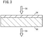
- a wavelength conversion film 54 contains the luminescent substance particle produced by the above production method, and acts to convert a light 56 in the ultraviolet region to a light 58 in the infrared region.
- the wavelength conversion film 54 is formed, e.g., on a surface of a quartz glass 60.
- the wavelength conversion film 54 may be produced as follows. Thus, the luminescent substance particles are dispersed in a liquid phase, and application of the dispersion is performed to thereby produce the wavelength conversion film 54.
- Step S1 of FIG. 4 an ethanol solution is added into a container containing a powder of the luminescent substance particle.
- Step S2 the luminescent substance particle powder in the container is ultrasonic-dispersed.
- a polysiloxane oligomer-containing coating material such as GLASCA HP7003 (trade name) available from JSR Corporation, is added to the container.
- the polysiloxane oligomer-containing coating material is a solution containing a polysiloxane oligomer derived from an alkoxysilane. The solution is applied and dried to thereby form a strong transparent coating having a main skeleton of a siloxane bond network structure -(Si-O) n -.
- Step S4 the luminescent substance particle powder in the container is ultrasonic-dispersed to prepare a film-forming slurry.
- Step S5 the film-forming slurry is applied to the surface of the quartz glass 60 or the like. For example, the surface is spin-coated with the film-forming slurry.
- Step S6 the film-forming slurry applied to the quartz glass 60 is dried at ordinary temperature. By such drying, the liquid phase is hardened while incorporating the luminescent substance particle therein. Consequently, a strong wavelength conversion film 54 thus-obtained has the main skeleton of the siloxane bond network structure -(Si-O) n - as described above.
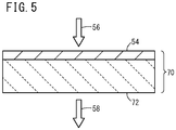
- a wavelength conversion device 70 has a substrate 72, and further has the above-described wavelength conversion film 54 formed on one main surface of the substrate 72.
- the substrate 72 the above quartz glass 60, a soda glass for a solar battery, etc. may be used.
- a flexible transparent resin sheet, a composite sheet containing a resin and an inorganic material, or the like may be used as the substrate 72.
- the substrate 72 is preferably a transparent film.
- a main portion of a solar battery 80 has a plurality of power generation cells 82 arranged in a plane, a sealing layer 84 formed so as to cover the power generation cells 82, a glass 86 formed on the sealing layer 84, and the wavelength conversion film 54 formed on a front surface of the glass 86.
- the sealing layer 84 may be composed of a light-transmitting sealant resin such as a polyethylene-polyvinyl acetate copolymer (EVA).
- EVA polyethylene-polyvinyl acetate copolymer
- the sealing layer 84 preferably has a light transmittance of 80% or more in a wavelength region of 200 to 800 nm.
- the glass 86 is a protection glass, and generally uses a soda glass.
- the wavelength conversion film 54 may be formed on a front surface or a rear surface of at least one component of the solar battery 80.
- the wavelength conversion device 70 may be disposed between a plurality of components of the solar battery 80 or on a light incident surface of the solar battery 80.
- the wavelength conversion film 54 or the wavelength conversion device 70 may be located between the power generation cells 82 and the solar light incident surface.
- the glass 86 the protection glass, generally containing the soda glass
- the sealing layer 84 containing a resin such as EVA
- the wavelength conversion layer contains an organic material.
- the document gives a suggestion that it is not preferable to form the wavelength conversion layer on the outermost surface exposed to external air.
- the wavelength conversion film 54 since the wavelength conversion film 54 is composed of the inorganic material, the wavelength conversion film 54 can be disposed on the outermost surface.
- the formation position of the wavelength conversion film 54 or the wavelength conversion device 70 can be arbitrarily selected, and the design flexibility can be increased.
- an ultraviolet-transmittable quartz glass is used as a protection glass.
- the quartz glass is highly costly, and therefore cannot be actually used in a solar battery.
- XRD patterns of luminescent substance particles of Samples 1 to 18 were evaluated. Furthermore, light emission intensities of the luminescent substance particles of Samples 1 to 18 were evaluated in the fluorescence spectra. Each fluorescence spectrum was obtained by emitting lights with various excitation wavelengths to the luminescent substance particle thereof. Furthermore, effects of Fe or Cr addition on internal quantum efficiency were evaluated.
- a Ba source and a Sn source were reacted by a plasma synthesis process to thereby produce the luminescent substance particle of Sample 1.
- 5.000% by mole of Fe was added to 1 mol of Sn in the Sn source.
- the Fe cation addition was carried out in the plasma synthesis process as follows. Fe (NO 3 ) 3 ⁇ 9H 2 O was added to and dissolved in ethanol, and a BaCO 3 powder and a SnO 2 powder were ground and mixed in the ethanol solution as described above, while the Fe amount per 1 mol of Sn in the Sn source is controlled to be a specified mole ratio.
- the luminescent substance particle of Sample 2 was produced in the same manner as Sample 1 except that 1.000% by mole of Fe was added to 1 mol of Sn in the Sn source.
- the luminescent substance particle of Sample 3 was produced in the same manner as Sample 1 except that 0.500% by mole of Fe was added to 1 mol of Sn in the Sn source.
- the luminescent substance particle of Sample 4 was produced in the same manner as Sample 1 except that 0.100% by mole of Fe was added to 1 mol of Sn in the Sn source.
- the luminescent substance particle of Sample 5 was produced in the same manner as Sample 1 except that 0.050% by mole of Fe was added to 1 mol of Sn in the Sn source.
- the luminescent substance particle of Sample 6 was produced in the same manner as Sample 1 except that 0.010% by mole of Fe was added to 1 mol of Sn in the Sn source.
- a Ba source and a Sn source were reacted by a plasma synthesis process to thereby produce the luminescent substance particle of Sample 7.
- 1.000% by mole of Cr was added to 1 mol of Sn in the Sn source.
- the Cr cation addition was carried out in the plasma synthesis process as follows. CrCl 3 ⁇ 6H 2 O was added to and dissolved in ethanol, and a BaCO 3 powder and a SnO 2 powder were ground and mixed in the ethanol solution as described above, while the Cr amount per 1 mol of Sn in the Sn source is controlled to be a specified mole ratio.
- the luminescent substance particle of Sample 8 was produced in the same manner as Sample 7 except that 0.100% by mole of Cr was added to 1 mol of Sn in the Sn source.
- the luminescent substance particle of Sample 9 was produced in the same manner as Sample 7 except that 0.050% by mole of Cr was added to 1 mol of Sn in the Sn source.
- the luminescent substance particle of Sample 10 was produced in the same manner as Sample 7 except that 0.010% by mole of Cr was added to 1 mol of Sn in the Sn source.
- the luminescent substance particle of Sample 11 was produced in the same manner as Sample 7 except that 0.005% by mole of Cr was added to 1 mol of Sn in the Sn source.
- the luminescent substance particle of Sample 12 was produced in the same manner as Sample 7 except that 0.001% by mole of Cr was added to 1 mol of Sn in the Sn source.
- a Ba source and a Sn source were reacted by a plasma synthesis process to thereby produce the luminescent substance particle of Sample 13.
- 1.000% by mole of Ni was added to 1 mol of Sn in the Sn source.
- the Ni cation addition was carried out in the plasma synthesis process as follows. Ni(NO 3 ) 2 ⁇ 6H 2 O was added to and dissolved in ethanol, and a BaCO 3 powder and a SnO 2 powder were ground and mixed in the ethanol solution as described above, while the Ni amount per 1 mol of Sn in the Sn source is controlled to be a specified mole ratio.
- the luminescent substance particle of Sample 14 was produced in the same manner as Sample 13 except that 0.100% by mole of Ni was added to 1 mol of Sn in the Sn source.
- the luminescent substance particle of Sample 15 was produced in the same manner as Sample 13 except that 0.050% by mole of Ni was added to 1 mol of Sn in the Sn source.
- the luminescent substance particle of Sample 16 was produced in the same manner as Sample 13 except that 0.010% by mole of Ni was added to 1 mol of Sn in the Sn source.
- the luminescent substance particle of Sample 17 was produced in the same manner as Sample 13 except that 0.005% by mole of Ni was added to 1 mol of Sn in the Sn source.
- the luminescent substance particle of Sample 18 was produced in the same manner as Sample 13 except that 0.001% by mole of Ni was added to 1 mol of Sn in the Sn source.
- FIG. 7A A typical XRD pattern of the luminescent substance particle of Sample 1 is shown in FIG. 7A .
- the XRD pattern is approximately equal to that of the cubic crystal BaSnO 3 .
- a TEM microstructure of the luminescent substance particle of Sample 1 is shown in FIG. 7B . As evident from FIG. 7B , it was confirmed that the luminescent substance particles having particle diameters of about 10 to 40 nm were formed.
- the Fe contents of Samples 2, 3, and 4 were 0.20000%, 0.04000%, and 0.02000% by mass, respectively.
- the Fe content of Sample 6 was obtained based on the added Fe amount using the above line equation. As a result, the Fe content was 0.00161% by mass.
- Samples 8 and 9 were 0.02000% and 0.01000% by mass, respectively.
- the Cr content of Sample 11 was obtained based on the added Cr amount using the above line equation. As a result, the Cr content was 0.00061% by mass.
- the Cr content of Sample 12 was obtained based on the added Cr amount using the above line equation. As a result, the Cr content was 0.00012% by mass.
- Ni content a non-standard semi-quantitative analysis of the obtained fluorescent X-ray spectrum was carried out based on an FP method. As a result, the Ni content was 0.22000% by mass.
- Samples 14 and 15 were 0.02000% and 0.01000% by mass, respectively.
- the Ni content of Sample 17 was obtained based on the added Ni amount using the above line equation. As a result, the Ni content was 0.00110% by mass.
- the Ni content of Sample 18 was obtained based on the added Ni amount using the above line equation. As a result, the Ni content was 0.00022% by mass.
- An internal quantum efficiency of a specimen of the luminescent substance particle of Sample 1 was measured by using a spectrofluorophotometer (FP-8600 available from JASCO Corporation) and a ⁇ 60-mm integrating sphere.
- the specimen of Sample 1 was irradiated with an excitation light having a wavelength of 360 nm.
- the specimen of Sample 1 had an internal quantum efficiency of 1%.
- the curve Lfe is a characteristic curve representing the internal quantum efficiency changes with the Fe content
- the curve Lcr is a characteristic curve representing the internal quantum efficiency changes with the Cr content
- the curve Lni is a characteristic curve representing the internal quantum efficiency changes with the Ni content.
- the internal quantum efficiency of 50% was considered as the maximum performance, and the internal quantum efficiency of 10% was considered as the minimum performance required for achieving an output increase effect.
- the internal quantum efficiency of 30% was considered as an intermediate level between 50% and 10%.
- the Fe content should be 0.0700% by mass or less, preferably 0.0300% by mass or less, more preferably 0.0050% by mass or less.
- the Fe amount should be 0.435% by mole or less, preferably 0.187% by mole or less, more preferably 0.031% by mole or less, per 1 mol of Sn in the Sn source.
- the Cr content should be 0.0050% by mass or less, preferably 0.0020% by mass or less, more preferably 0.0004% by mass or less.
- the Cr amount should be 0.041% by mole or less, preferably 0.017% by mole or less, more preferably 0.003% by mole or less, per 1 mol of Sn in the Sn source.
- the Ni content should be 0.0200% by mass or less, preferably 0.0040% by mass or less, more preferably 0.0007% by mass or less.
- the Ni amount should be 0.091% by mole or less, preferably 0.018% by mole or less, more preferably 0.003% by mole or less, per 1 mol of Sn in the Sn source.
- a solar battery of Example 1 has a plurality of the power generation cells 82 arranged in a plane, the sealing layer 84 formed so as to cover the power generation cells 82, the glass 86 formed on the sealing layer 84, and the wavelength conversion film 54 formed on a surface of the glass 86.
- the luminescent substance particle contained in the wavelength conversion film 54 was prepared as follows. A Ba source and a Sn source were reacted by a plasma synthesis process, 0.500% by mole of Fe being added to 1 mol of Sn in the Sn source in the same manner as Sample 3. The luminescent substance particle had a Fe content of 0.04000% by mass.
- a solar battery of Example 2 was produced in the same manner as Example 1 except that the luminescent substance particle in the wavelength conversion film 54 was prepared by adding 0.010% by mole of Fe to 1 mol of Sn in the Sn source as in Sample 6.
- the luminescent substance particle had a Fe content of 0.00161% by mass.
- a solar battery of Example 3 was produced in the same manner as Example 1 except that the luminescent substance particle in the wavelength conversion film 54 was prepared by adding 0.010% by mole of Cr to 1 mol of Sn in the Sn source as in Sample 10.
- the luminescent substance particle had a Cr content of 0.00121% by mass.
- a solar battery of Example 4 was produced in the same manner as Example 1 except that the luminescent substance particle in the wavelength conversion film 54 was prepared by adding 0.001% by mole of Cr to 1 mol of Sn in the Sn source as in Sample 12.
- the luminescent substance particle had a Cr content of 0.00012% by mass.
- a solar battery of Example 5 was produced in the same manner as Example 1 except that the luminescent substance particle in the wavelength conversion film 54 was prepared by adding 0.010% by mole of Ni to 1 mol of Sn in the Sn source as in Sample 16.
- the luminescent substance particle had a Ni content of 0.00220% by mass.
- a solar battery of Example 6 was produced in the same manner as Example 1 except that the luminescent substance particle in the wavelength conversion film 54 was prepared by adding 0.001% by mole of Ni to 1 mol of Sn in the Sn source as in Sample 18.
- the luminescent substance particle had a Ni content of 0.00022% by mass.
- a solar battery of Example 7 was produced in the same manner as Example 1 except that the luminescent substance particle in the wavelength conversion film 54 was prepared as follows. A Ba source and a Sn source were reacted by a plasma synthesis process, none of Fe, Cr, and Ni being added to 1 mol of Sn in the Sn source.
- a solar battery of Example 8 was produced in the same manner as Example 1 except that the luminescent substance particle in the wavelength conversion film 54 was prepared as follows.
- a Ba source and a Sn source were reacted by a microwave hydrothermal synthesis process, none of Fe, Cr, and Ni being added to 1 mol of Sn in the Sn source.
- a solar battery of Example 9 was produced in the same manner as Example 1 except that the luminescent substance particle in the wavelength conversion film 54 was prepared as follows.
- a Ba source and a Sn source were reacted by a supercritical hydrothermal synthesis process using a titanium alloy container, none of Fe, Cr, and Ni being added to 1 mol of Sn in the Sn source.
- a solar battery of Example 10 was produced in the same manner as Example 1 except that the luminescent substance particle in the wavelength conversion film 54 was prepared as follows.
- a Ba source and a Sn source were reacted by a spray pyrolysis synthesis process, none of Fe, Cr, and Ni being added to 1 mol of Sn in the Sn source.
- a solar battery of Comparative Example 1 has a plurality of the power generation cells 82 arranged in a plane, the sealing layer 84 formed on the power generation cells 82, and the glass 86 formed on the sealing layer 84.
- a solar battery of Comparative Example 2 was produced in the same manner as Example 1 except that the luminescent substance particle in the wavelength conversion film 54 was prepared by adding 1.000% by mole of Fe to 1 mol of Sn in the Sn source as in Sample 2.
- the luminescent substance particle had a Fe content of 0.20000% by mass.
- a solar battery of Comparative Example 3 was produced in the same manner as Example 1 except that the luminescent substance particle in the wavelength conversion film 54 was prepared by adding 0.050% by mole of Cr to 1 mol of Sn in the Sn source as in Sample 9.
- the luminescent substance particle had a Cr content of 0.01000% by mass.
- a solar battery of Comparative Example 4 was produced in the same manner as Example 1 except that the luminescent substance particle in the wavelength conversion film 54 was prepared by adding 0.100% by mole of Ni to 1 mol of Sn in the Sn source as in Sample 14.
- the luminescent substance particle had a Ni content of 0.02000% by mass.
- Luminescent substance particle production method in Table 6, the term “Plasma” means the method containing the plasma synthesis process, the term “Microwave” means the method containing the microwave hydrothermal synthesis process, the term “Supercritical” means the method containing the supercritical hydrothermal synthesis process using the titanium alloy container, and the term “Spray” means the method containing the spray pyrolysis synthesis process.
- Table 6 Luminescent substance particle production method Additive element Added element amount per 1 mol of Sn in Sn source (% by mole) Internal quantum efficiency (%) Power generation amount (mW/cm 2 ) Output increase (%) Comp. Ex. 1 No luminescent substance particle 12.20 0 No wavelength conversion film Comp. Ex.
- the power generation amounts of Comparative Examples 1, 3, and 4 were 12.20 (mW/cm 2 ).
- the power generation amount of Comparative Example 2 was smaller than that of Comparative Example 1.
- the power generation amounts of Examples 1 to 10 were larger than that of Comparative Example 1.
- a larger power generation amount was obtained when a smaller amount of Fe was added to the luminescent substance particle contained in the wavelength conversion film 54.
- Cr and Ni see Examples 3 to 6). That is, a larger power generation amount was obtained when a smaller amount of Cr or Ni was added to the luminescent substance particle contained in the wavelength conversion film 54.
- the power generation amount is further increased when none of Fe, Cr, and Ni is added in the process for producing the luminescent substance particle.
- the supercritical hydrothermal synthesis process using the titanium alloy container is preferred, the microwave hydrothermal synthesis process is more preferred, and the plasma synthesis process and the spray pyrolysis synthesis process are most preferred.
- the luminescent substance particle, the luminescent substance particle production method, the luminescent substance film, the wavelength conversion film, the wavelength conversion device, and the solar battery of the present invention are not limited to the above-described embodiments, and various changes and modifications may be made therein without departing from the scope of the invention.
Landscapes
- Chemical & Material Sciences (AREA)
- Organic Chemistry (AREA)
- Inorganic Chemistry (AREA)
- Engineering & Computer Science (AREA)
- Materials Engineering (AREA)
- Life Sciences & Earth Sciences (AREA)
- Geology (AREA)
- Luminescent Compositions (AREA)
- Photovoltaic Devices (AREA)
Abstract
Description
- The present invention relates to a luminescent substance particle (fine fluorescent particles) of a perovskite-type oxide and a method for producing the luminescent substance particle (process for producing fine fluorescent particles), and relates to a luminescent substance film (thin fluorescent film), a wavelength conversion film, a wavelength conversion device, and a solar battery (solar cell) using the luminescent substance particle.
- Japanese Patent No.
3698215 Non-Patent Document 1 and Japanese Laid-Open Patent Publication No.2007-146102 2013-004806 -
- Non-Patent Document 1: Hiroshi Mizoguchi, Patrick M. Woodward, Cheol-Hee Park, and Douglas A. Keszler, "Strong Near-Infrared Luminescence in BaSnO3", J. Am. Chem. Soc., 2004, 126, 9796-9800
- Non-Patent Document 2: Yosuke Ohya, Yuichiro Kuroki, Tomoichiro Okamoto, and Masasuke Takata, " Influence of Composition in Near-infrared Luminescence of BaSnxO3", Abstract 3L10, Annual Meeting 2014, The Ceramic Society of Japan
- Specifically, Japanese Patent No.
3698215 - Non-Patent
Document 1 discloses that BaSnO3 exhibits an emission spectrum of about 800 to 1100 nm under an excitation spectrum of 300 to 400 nm. This document discloses a method containing preparing BaSn(OH)6 via a hydrothermal synthesis and thermally decomposing the BaSn(OH)6 to obtain the BaSnO3. This document is silent about the particle diameter of the BaSnO3, but discloses a crystallite size of 100 to 350 nm. Furthermore, this document discloses that there is no relationship between the particle diameter and light emission intensity. - Japanese Laid-Open Patent Publication No.
2007-146102 - Japanese Laid-Open Patent Publication No.
2013-004806 - Non-Patent Document 2 discloses that the luminescence of the BaSnxO3 (0.8 ≤ x ≤ 1.6) exhibits a peak at the near-infrared region wavelength of 890 nm, and exhibits the maximum light emission intensity when the feed composition ratio x of Sn to Ba is 1.3.
- However, the wavelength conversion material of Japanese Patent No.
3698215 - Non-Patent
Document 1 clarifies that the BaSnO3 exhibits an emission spectrum of about 800 to 1100 nm under an excitation spectrum of 300 to 400 nm, and thus exhibits a large wavelength shift amount. Although it is preferred that the wavelength conversion component does not inhibit visible light transmission, Non-PatentDocument 1 does not consider the visible light transmission. - The materials of Japanese Patent No.
3698215 2007-146102 - The wavelength conversion layer of Japanese Laid-Open Patent Publication No.
2013-004806 - Japanese Patent No.
3698215 2007-146102 Documents 1 and 2 do not disclose internal quantum efficiencies. Japanese Laid-Open Patent Publication No.2013-004806 - In view of the future trends, for example, there is a demand for improving power generation efficiency of a solar battery not only by increasing the wavelength shift amount, but also by increasing the transparency and preventing the reduction of the internal quantum efficiency. Furthermore, it will be necessary to reduce the production cost.
- In view of the above problems, an object of the present invention is to provide a luminescent substance particle and a production method thereof having the following advantageous effects:
- (a-1) the wavelength shift amount can be increased;
- (a-2) the transparency can be increased, and the reduction of the internal quantum efficiency can be prevented; and
- (a-3) the power generation efficiency of a solar battery or the like can be improved, and the production cost can be reduced.
- Another object of the present invention is to provide a luminescent substance film, a wavelength conversion film, and a wavelength conversion device having the following advantageous effects:
- (b-1) the wavelength shift amount can be increased; and
- (b-2) the transparency can be increased, the power generation efficiency of a solar battery or the like can be improved, and the production cost can be reduced.
- A further object of the present invention is to provide a solar battery that uses the luminescent substance particle, the wavelength conversion film, or the wavelength conversion device to have the following advantageous effects:
- (c-1) the power generation efficiency can be increased; and
- (c-2) the mounting position of the wavelength conversion film or a component having a wavelength conversion function can be arbitrarily selected, and thus the design flexibility can be increased.
- [1] According to a first aspect of the present invention, there is provided a luminescent substance particle comprising BaSnO3 having a perovskite-type structure, wherein the luminescent substance particle contains Fe (iron), a content of Fe being 0.07% by mass or less. The Fe content is preferably 0.03% by mass or less, more preferably 0.005% by mass or less.
- [2] According to a second aspect of the present invention, there is provided a luminescent substance particle comprising BaSnO3 having a perovskite-type structure, wherein the luminescent substance particle contains Cr (chromium), a content of Cr being 0.005% by mass or less. The Cr content is preferably 0.002% by mass or less, more preferably 0.0004% by mass or less.
- [3] According to a third aspect of the present invention, there is provided a luminescent substance particle comprising BaSnO3 having a perovskite-type structure, wherein the luminescent substance particle contains Ni (nickel), a content of Ni being 0.02% by mass or less. The Ni content is preferably 0.004% by mass or less, more preferably 0.0007% by mass or less.
- [4] In the first to third aspects, the luminescent substance particle has a particle diameter of 100 nm or less.
- [5] According to a fourth aspect of the present invention, there is provided a method for producing the luminescent substance particle of the first aspect. The method includes the step of carrying out a reaction of a Ba (barium) source and a Sn (tin) source. In the method, 0.435% by mole or less of Fe is added to 1 mol of Sn in the Sn source, and at least Fe is not eluted from an apparatus used for the reaction. The added Fe amount per 1 mol of Sn in the Sn source is preferably 0.187% by mole or less, more preferably 0.031% by mole or less.
- [6] According to a fifth aspect of the present invention, there is provided a method for producing the luminescent substance particle of the second aspect. The method includes the step of carrying out a reaction of a Ba (barium) source and a Sn (tin) source. In the method, 0.041% by mole or less of Cr is added to 1 mol of Sn in the Sn source, and at least Cr is not eluted from an apparatus used for the reaction. The added Cr amount per 1 mol of Sn in the Sn source is preferably 0.017% by mole or less, more preferably 0.003% by mole or less.
- [7] According to a sixth aspect of the present invention, there is provided a method for producing the luminescent substance particle of the third aspect. The method includes the step of carrying out a reaction of a Ba (barium) source and a Sn (tin) source. In the method, 0.091% by mole or less of Ni is added to 1 mol of Sn in the Sn source, and at least Ni is not eluted from an apparatus used for the reaction. The added Ni amount per 1 mol of Sn in the Sn source is preferably 0.018% by mole or less, more preferably 0.003% by mole or less.
- [8] In the fourth to sixth aspects, the step of carrying out the reaction is preferably performed by a plasma synthesis process.
- [9] In the fourth to sixth aspects, the step of carrying out the reaction is preferably performed by a microwave hydrothermal synthesis process.
- [10] In the fourth to sixth aspects, the step of carrying out the reaction is preferably performed by a supercritical hydrothermal synthesis process using a titanium alloy container.
- [11] In the fourth to sixth aspects, the step of carrying out the reaction is preferably performed by a spray pyrolysis synthesis process.
- [12] According to a seventh aspect of the present invention, there is provided a luminescent substance film including the luminescent substance particle of the first to third aspects or the luminescent substance particle produced by the method of the fourth to sixth aspects.
- [13] According to an eighth aspect of the present invention, there is provided a wavelength conversion film for converting a light in the ultraviolet region to a light in the infrared region, including the luminescent substance particle of the first to third aspects or the luminescent substance particle produced by the method of the fourth to sixth aspects.
- [14] According to a ninth aspect of the present invention, there is provided a wavelength conversion film obtained by dispersing the luminescent substance particle of the first to third aspects or the luminescent substance particle produced by the method of the fourth to sixth aspects in a liquid phase and then applying the liquid phase.
- [15] In this case, the liquid phase may contain a compound for forming a siloxane bond, and may be hardened while incorporating the luminescent substance particle therein.
- [16] According to a tenth aspect of the present invention, there is provided a wavelength conversion device including a substrate and the wavelength conversion film of the eighth or ninth aspect formed on the substrate.
- [17] In this case, the substrate may be a flexible resin sheet or a composite sheet containing a resin and an inorganic material.
- [18] According to an eleventh aspect of the present invention, there is provided a solar battery including, in at least one component of the solar battery, the luminescent substance particle of the first to third aspects or the luminescent substance particle produced by the method of the fourth to sixth aspects.
- [19] According to a twelfth aspect of the present invention, there is provided a solar battery including the wavelength conversion film of the eighth or ninth aspect formed on a front surface or a rear surface of at least one component of the solar battery.
- [20] According to a thirteenth aspect of the present invention, there is provided a solar battery including the wavelength conversion device of the tenth aspect disposed between a plurality of components of the solar battery or on a light incident surface thereof.
- The luminescent substance particle and the luminescent substance particle production method of the present invention are capable of increasing the wavelength shift amount, increasing the transparency, preventing the reduction of the internal quantum efficiency, and for example, improving the power generation efficiency of the solar battery.
- The luminescent substance film, the wavelength conversion film, and the wavelength conversion device of the present invention are capable of increasing the wavelength shift amount, and for example, improving the power generation efficiency of the solar battery.
- The solar battery of the present invention uses the luminescent substance particle, the wavelength conversion film, or the wavelength conversion device, and thereby can exhibit an improved power generation efficiency. In addition, in the solar battery, the position of the wavelength conversion film or a component having a wavelength conversion function can be arbitrarily selected, and thus the design flexibility can be increased.
-
-
FIG. 1 is a view for illustrating a crystal structure of luminescent substance particles according to first to third embodiments of the present invention; -
FIG. 2 is a cross-sectional view of a luminescent substance film according to an embodiment of the present invention formed on a substrate; -
FIG. 3 is a cross-sectional view of a wavelength conversion film according to an embodiment of the present invention formed on a quartz glass; -
FIG. 4 is a flow chart of an example of a method for producing the wavelength conversion film; -
FIG. 5 is a cross-sectional view of a wavelength conversion device according to an embodiment of the present invention; -
FIG. 6 is a cross-sectional view of a main portion of a solar battery; -
FIG. 7A is an XRD pattern of a luminescent substance particle ofSample 1, andFIG. 7B is a photograph of a microstructure of the luminescent substance particle ofSample 1 taken by a TEM (transmission electron microscope) (hereinafter referred to simply as the TEM microstructure); -
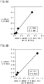
FIG. 8A is a graph showing results ofSamples 1 to 4, the x-axis representing added Fe amount (% by mole) per 1 mol of material, and the y-axis representing Fe content (% by mass), andFIG. 8B is a graph showing results of Samples 7 to 9, the x-axis representing added Cr amount (% by mole) per 1 mol of material, and the y-axis representing Cr content (% by mass); -
FIG. 9 is a graph showing results of Samples 13 to 15, the x-axis representing added Ni amount (% by mole) per 1 mol of material, and the y-axis representing Ni content (% by mass); -
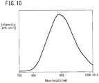
FIG. 10 is a fluorescence spectrum of the luminescent substance particle ofSample 1 under an excitation light with a wavelength of 360 nm; -
FIG. 11 is a graph showing changes of internal quantum efficiency with Fe, Cr, and Ni contents based on results ofSamples 1 to 18, wherein the Fe, Cr, and Ni content values of less than 0.01% by mass are outside the detectable range, and therefore the values are estimated from the approximate lines ofFIGS. 8A, 8B , and9 ; and -
FIG. 12 is a cross-sectional view of a main portion of a solar battery according to Comparative Example 1. - Several embodiments of luminescent substance particles, a luminescent substance particle production method, a luminescent substance film, a wavelength conversion film, a wavelength conversion device, and a solar battery of the present invention will be described below with reference to
FIGS. 1 to 12 . It should be noted that, in this description, a numeric range of "A to B" includes both the numeric values A and B as the lower limit and upper limit values. - A luminescent substance particle according to a first embodiment (hereinafter referred to as the first luminescent substance particle) has BaSnO3 having a perovskite-type structure, and contains 0.07% by mass or less of Fe (iron). The Fe content is preferably 0.03% by mass or less, more preferably 0.005% by mass or less.
- A luminescent substance particle according to a second embodiment (hereinafter referred to as the second luminescent substance particle) has BaSnO3 having a perovskite-type structure, and contains 0.005% by mass or less of Cr (chromium). The Cr content is preferably 0.002% by mass or less, more preferably 0.0004% by mass or less.
- A luminescent substance particle according to a third embodiment (hereinafter referred to as the third luminescent substance particle) has BaSnO3 having a perovskite-type structure, and contains 0.02% by mass or less of Ni (nickel). The Ni content is preferably 0.004% by mass or less, more preferably 0.0007% by mass or less.
- The first to third luminescent substance particles have a perovskite-type crystal structure shown in
FIG. 1 . In the crystal structure, the Ba (barium) atoms are located at the corner positions, the Sn (tin) atom is located at the body center position, and the O (oxygen) atoms are located at the face center positions around the body center Sn. - A method for producing the first to third luminescent substance particles contains a process of carrying out a reaction of a Ba (barium) source and a Sn (tin) source.
- In production of the first luminescent substance particle, it is preferred that 0.435% by mole or less of Fe is added to 1 mol of Sn (material) in the Sn source. In this case, the reduction of the internal quantum efficiency is prevented. The Fe amount is preferably 0.187% by mole or less, more preferably 0.031% by mole or less, per 1 mol of Sn in the Sn source. From the viewpoint of preventing the reduction of the internal quantum efficiency, it is preferred that at least Fe is not eluted from an apparatus for the reaction. It is more preferred that Fe and Cr are not eluted from the apparatus, and it is further preferred that Fe, Cr, and Ni are not eluted from the apparatus.
- In production of the second luminescent substance particle, it is preferred that 0.041% by mole or less of Cr is added to 1 mol of Sn in the Sn source. In this case, the reduction of the internal quantum efficiency is prevented. The Cr amount is preferably 0.017% by mole or less, more preferably 0.003% by mole or less, per 1 mol of Sn in the Sn source. From the viewpoint of preventing the reduction of the internal quantum efficiency, it is preferred that at least Cr is not eluted from the apparatus for the reaction. It is more preferred that Cr and Fe are not eluted from the apparatus, and it is further preferred that Cr, Fe, and Ni are not eluted from the apparatus.
- In production of the third luminescent substance particle, it is preferred that 0.091% by mole or less of Ni is added to 1 mol of Sn in the Sn source. In this case, the reduction of the internal quantum efficiency is prevented. The Ni amount is preferably 0.018% by mole or less, more preferably 0.003% by mole or less, per 1 mol of Sn in the Sn source. From the viewpoint of preventing the reduction of the internal quantum efficiency, it is preferred that at least Ni is not eluted from the apparatus for the reaction. It is more preferred that Ni and Fe are not eluted from the apparatus, and it is further preferred that Ni, Fe, and Cr are not eluted from the apparatus.
- In the method for producing the first to third luminescent substance particles, for example, the process of carrying out the reaction may be a plasma synthesis process, a microwave hydrothermal synthesis process, a supercritical hydrothermal synthesis process using a titanium alloy container, a spray pyrolysis synthesis process, etc.
- In the plasma synthesis process, a BaCO3 powder is used as the Ba source, and a SnO2 powder is used as the Sn source, in such a manner that the amount of Sn is equivalent to the amount of Ba by mole. The sources and ethanol are added into an agate mortar, and the sources are ground and mixed until the mixture loses fluidity due to evaporation of the ethanol. Then, the resultant is dried by a dryer or the like to thereby obtain a mixture powder as a starting material for the plasma synthesis. The mixture powder is introduced into a plasma chamber at a high temperature to thereby produce a BaSnO3 particle powder.
- In the microwave hydrothermal synthesis process, Ba(OH)2 is used as the Ba source, and a SnO2 sol is used as the Sn source. The sources and an appropriate amount of water are added together with a stirrer chip made of TEFLON (trademark) into a pressure-resistant resin container having an inner coating of TEFLON (trademark), and the container is sealed. The inside of the container is heated to 270°C by irradiating with a microwave at a maximum output of 600 W while stirring the mixture liquid in the container. The mixture liquid is maintained in the hydrothermal state for at least 10 hours to thereby obtain an aqueous solution containing BaSnO3 particles dispersed. The aqueous solution is subjected to a centrifugation treatment, the supernatant is removed, pure water is added to the resultant, and this is subjected to the centrifugation treatment again. The water addition and the centrifugation treatment are repeated, and the resultant is dried by a dryer to thereby obtain a BaSnO3 particle powder. The Ba source and the Sn source are not limited to the above compounds, and may be selected from chlorides, nitric acid compounds, and the like.
- In the supercritical hydrothermal synthesis process using the titanium alloy container, Ba(OH)2 is used as the Ba source, and a SnO2 sol is used as the Sn source. The sources and an appropriate amount of water are added into a pressure-resistant container made of a titanium alloy, and the container is sealed. The mixture is heated to 400°C by a dryer or the like, and is maintained in the supercritical hydrothermal state for at least 1 hour, to thereby obtain an aqueous solution containing BaSnO3 particles dispersed. The aqueous solution is subjected to a centrifugation treatment, the supernatant is removed, pure water is added to the resultant, and this is subjected to the centrifugation treatment again. The water addition and the centrifugation treatment are repeated, and the resultant is dried by a dryer to thereby obtain a BaSnO3 particle powder. The Ba source and the Sn source are not limited to the above compounds, and may be selected from chlorides, nitric acid compounds, and the like.
- In the spray pyrolysis synthesis process, BaCl2 is used as the Ba source, and SnCl2 is used as the Sn source, in such a manner that the amount of Sn is equivalent to the amount of Ba by mole. The sources are dissolved in water to prepare an aqueous solution of a starting material. The aqueous solution is sprayed and introduced into a reaction container at a high temperature to thereby produce a BaSnO3 particle powder. The Ba source and the Sn source are not limited to the above compounds, and may be selected from hydroxides, nitric acid compounds, and the like.
- In the spray pyrolysis synthesis process, a salt-assisted spray pyrolysis synthesis may be carried out. The salt-assisted spray pyrolysis synthesis is characterized by the following steps. An inorganic compound of an element other than the elements for the target material particle is dissolved in a solution containing the sources, and this solution is subjected to the spray pyrolysis to thereby prepare an agglomerated particle. The structure of the agglomerated particle is such that a primary particle containing the elements for the target material is located inside the inorganic compound. Then, the inorganic compound is separated from the agglomerated particle to thereby produce the primary particle.
- The composition of the luminescent substance particle may be measured by an energy dispersive X-ray analyzer. The crystal structure of the luminescent substance particle may be measured by a powder X-ray diffractometer (XRD). The particle diameter of the luminescent substance particle may be measured by observation using an electron microscope such as a transmission electron microscope (TEM).
- The particle diameter of the luminescent substance particle is the diameter of the particle that is not subjected to a secondary treatment such as a grinding treatment or a classification treatment. The average particle diameter may be the average of the particle diameters of the luminescent substance particles contained in the observation area of the electron microscope.
- A
luminescent substance film 50 shown inFIG. 2 according to an embodiment of the present invention contains the luminescent substance particle produced by the above production method. The method for forming theluminescent substance film 50 is not particularly limited and may be appropriately selected depending on the intended use, as long as theluminescent substance film 50 contains the luminescent substance particle. For example, theluminescent substance film 50 may be produced by a common method such as a spray method or a dipping method. InFIG. 2 , theluminescent substance film 50 is formed on asubstrate 52. - As shown in
FIG. 3 , awavelength conversion film 54 according to an embodiment of the present invention contains the luminescent substance particle produced by the above production method, and acts to convert a light 56 in the ultraviolet region to a light 58 in the infrared region. Thewavelength conversion film 54 is formed, e.g., on a surface of aquartz glass 60. - The
wavelength conversion film 54 may be produced as follows. Thus, the luminescent substance particles are dispersed in a liquid phase, and application of the dispersion is performed to thereby produce thewavelength conversion film 54. - More specifically, in Step S1 of
FIG. 4 , an ethanol solution is added into a container containing a powder of the luminescent substance particle. In Step S2, the luminescent substance particle powder in the container is ultrasonic-dispersed. - Then, in Step S3, a polysiloxane oligomer-containing coating material, such as GLASCA HP7003 (trade name) available from JSR Corporation, is added to the container. The polysiloxane oligomer-containing coating material is a solution containing a polysiloxane oligomer derived from an alkoxysilane. The solution is applied and dried to thereby form a strong transparent coating having a main skeleton of a siloxane bond network structure -(Si-O)n-.
- In Step S4, the luminescent substance particle powder in the container is ultrasonic-dispersed to prepare a film-forming slurry. In Step S5, the film-forming slurry is applied to the surface of the
quartz glass 60 or the like. For example, the surface is spin-coated with the film-forming slurry. - In Step S6, the film-forming slurry applied to the
quartz glass 60 is dried at ordinary temperature. By such drying, the liquid phase is hardened while incorporating the luminescent substance particle therein. Consequently, a strongwavelength conversion film 54 thus-obtained has the main skeleton of the siloxane bond network structure -(Si-O)n- as described above. - As shown in
FIG. 5 , awavelength conversion device 70 according to an embodiment of the present invention has asubstrate 72, and further has the above-describedwavelength conversion film 54 formed on one main surface of thesubstrate 72. As thesubstrate 72, theabove quartz glass 60, a soda glass for a solar battery, etc. may be used. Alternatively, for example, as thesubstrate 72, a flexible transparent resin sheet, a composite sheet containing a resin and an inorganic material, or the like may be used. In this case, thesubstrate 72 is preferably a transparent film. - As shown in
FIG. 6 , a main portion of asolar battery 80 according to an embodiment of the present invention has a plurality ofpower generation cells 82 arranged in a plane, asealing layer 84 formed so as to cover thepower generation cells 82, aglass 86 formed on thesealing layer 84, and thewavelength conversion film 54 formed on a front surface of theglass 86. - For example, the
sealing layer 84 may be composed of a light-transmitting sealant resin such as a polyethylene-polyvinyl acetate copolymer (EVA). Thesealing layer 84 preferably has a light transmittance of 80% or more in a wavelength region of 200 to 800 nm. Theglass 86 is a protection glass, and generally uses a soda glass. - In another example of the solar battery 80 (not shown), the
wavelength conversion film 54 may be formed on a front surface or a rear surface of at least one component of thesolar battery 80. Alternatively, thewavelength conversion device 70 may be disposed between a plurality of components of thesolar battery 80 or on a light incident surface of thesolar battery 80. - In general, the
wavelength conversion film 54 or thewavelength conversion device 70 may be located between thepower generation cells 82 and the solar light incident surface. Incidentally, the glass 86 (the protection glass, generally containing the soda glass) and the sealing layer 84 (containing a resin such as EVA) absorb a part of an ultraviolet light. Therefore, it is more preferred that thewavelength conversion film 54 is arranged closer to the solar light incident surface. - As described above, in Japanese Laid-Open Patent Publication No.
2013-004806 wavelength conversion film 54 is composed of the inorganic material, thewavelength conversion film 54 can be disposed on the outermost surface. Thus, in the present invention, the formation position of thewavelength conversion film 54 or thewavelength conversion device 70 can be arbitrarily selected, and the design flexibility can be increased. In this regard, in Japanese Laid-Open Patent Publication No.2013-004806 - XRD patterns of luminescent substance particles of
Samples 1 to 18 were evaluated. Furthermore, light emission intensities of the luminescent substance particles ofSamples 1 to 18 were evaluated in the fluorescence spectra. Each fluorescence spectrum was obtained by emitting lights with various excitation wavelengths to the luminescent substance particle thereof. Furthermore, effects of Fe or Cr addition on internal quantum efficiency were evaluated. - A Ba source and a Sn source were reacted by a plasma synthesis process to thereby produce the luminescent substance particle of
Sample 1. In the production of the luminescent substance particle ofSample 1, 5.000% by mole of Fe was added to 1 mol of Sn in the Sn source. The Fe cation addition was carried out in the plasma synthesis process as follows. Fe (NO3)3·9H2O was added to and dissolved in ethanol, and a BaCO3 powder and a SnO2 powder were ground and mixed in the ethanol solution as described above, while the Fe amount per 1 mol of Sn in the Sn source is controlled to be a specified mole ratio. - The luminescent substance particle of Sample 2 was produced in the same manner as
Sample 1 except that 1.000% by mole of Fe was added to 1 mol of Sn in the Sn source. - The luminescent substance particle of
Sample 3 was produced in the same manner asSample 1 except that 0.500% by mole of Fe was added to 1 mol of Sn in the Sn source. - The luminescent substance particle of
Sample 4 was produced in the same manner asSample 1 except that 0.100% by mole of Fe was added to 1 mol of Sn in the Sn source. - The luminescent substance particle of
Sample 5 was produced in the same manner asSample 1 except that 0.050% by mole of Fe was added to 1 mol of Sn in the Sn source. - The luminescent substance particle of Sample 6 was produced in the same manner as
Sample 1 except that 0.010% by mole of Fe was added to 1 mol of Sn in the Sn source. - A Ba source and a Sn source were reacted by a plasma synthesis process to thereby produce the luminescent substance particle of Sample 7. In the production of the luminescent substance particle of Sample 7, 1.000% by mole of Cr was added to 1 mol of Sn in the Sn source. The Cr cation addition was carried out in the plasma synthesis process as follows. CrCl3·6H2O was added to and dissolved in ethanol, and a BaCO3 powder and a SnO2 powder were ground and mixed in the ethanol solution as described above, while the Cr amount per 1 mol of Sn in the Sn source is controlled to be a specified mole ratio.
- The luminescent substance particle of Sample 8 was produced in the same manner as Sample 7 except that 0.100% by mole of Cr was added to 1 mol of Sn in the Sn source.
- The luminescent substance particle of Sample 9 was produced in the same manner as Sample 7 except that 0.050% by mole of Cr was added to 1 mol of Sn in the Sn source.
- The luminescent substance particle of
Sample 10 was produced in the same manner as Sample 7 except that 0.010% by mole of Cr was added to 1 mol of Sn in the Sn source. - The luminescent substance particle of Sample 11 was produced in the same manner as Sample 7 except that 0.005% by mole of Cr was added to 1 mol of Sn in the Sn source.
- The luminescent substance particle of Sample 12 was produced in the same manner as Sample 7 except that 0.001% by mole of Cr was added to 1 mol of Sn in the Sn source.
- A Ba source and a Sn source were reacted by a plasma synthesis process to thereby produce the luminescent substance particle of Sample 13. In the production of the luminescent substance particle of Sample 13, 1.000% by mole of Ni was added to 1 mol of Sn in the Sn source. The Ni cation addition was carried out in the plasma synthesis process as follows. Ni(NO3)2·6H2O was added to and dissolved in ethanol, and a BaCO3 powder and a SnO2 powder were ground and mixed in the ethanol solution as described above, while the Ni amount per 1 mol of Sn in the Sn source is controlled to be a specified mole ratio.
- The luminescent substance particle of Sample 14 was produced in the same manner as Sample 13 except that 0.100% by mole of Ni was added to 1 mol of Sn in the Sn source.
- The luminescent substance particle of Sample 15 was produced in the same manner as Sample 13 except that 0.050% by mole of Ni was added to 1 mol of Sn in the Sn source.
- The luminescent substance particle of Sample 16 was produced in the same manner as Sample 13 except that 0.010% by mole of Ni was added to 1 mol of Sn in the Sn source.
- The luminescent substance particle of Sample 17 was produced in the same manner as Sample 13 except that 0.005% by mole of Ni was added to 1 mol of Sn in the Sn source.
- The luminescent substance particle of Sample 18 was produced in the same manner as Sample 13 except that 0.001% by mole of Ni was added to 1 mol of Sn in the Sn source.
- The details, the Fe, Cr, and Ni contents and the internal quantum efficiencies of
Samples 1 to 18 are shown in Tables 1, 2, and 3. Incidentally, the values of high-concentration Samples 1 to 4, 7 to 9, and 13 to 15 were measured values, and the values of low-concentration Samples Table 1 Added Fe amount per 1 mol of Sn in Sn source (% by mole) Fe content (% by mass) Internal quantum efficiency (%) Sample 15.000 0.80000 1 Sample 2 1.000 0.20000 3 Sample 30.500 0.04000 14 Sample 40.100 0.02000 38 Sample 50.050 0.00804 48 Sample 6 0.010 0.00161 51 Table 2 Added Cr amount per 1 mol of Sn in Sn source (% by mole) Cr content (% by mass) Internal quantum efficiency (%) Sample 7 1.000 0.12000 1 Sample 8 0.100 0.02000 1 Sample 9 0.050 0.01000 6 Sample 100.010 0.00121 36 Sample 11 0.005 0.00061 49 Sample 12 0.001 0.00012 51 Table 3 Added Ni amount per 1 mol of Sn in Sn source (% by mole) Ni content (% by mass) Internal quantum efficiency (%) Sample 13 1.000 0.22000 1 Sample 14 0.100 0.02000 7 Sample 15 0.050 0.01000 14 Sample 16 0.010 0.00220 40 Sample 17 0.005 0.00110 50 Sample 18 0.001 0.00022 52 - A typical XRD pattern of the luminescent substance particle of
Sample 1 is shown inFIG. 7A . The XRD pattern is approximately equal to that of the cubic crystal BaSnO3. A TEM microstructure of the luminescent substance particle ofSample 1 is shown inFIG. 7B . As evident fromFIG. 7B , it was confirmed that the luminescent substance particles having particle diameters of about 10 to 40 nm were formed. - XRD patterns and TEM microstructures of Samples 2 to 18 were similar to those of Sample 1 (
FIGS. 7A and 7B ). - Concerning Fe content, a non-standard semi-quantitative analysis of the obtained fluorescent X-ray spectrum was carried out based on an FP method. As a result, the Fe content was 0.80000% by mass.
- The Fe contents of
Samples - The Fe content was lower than the detection limit of the FP method using the fluorescent X-ray spectrum. Therefore, the Fe content was estimated as follows. As shown in
FIG. 8A , the data ofSamples 1 to 4 were plotted on an x-y graph. The x-axis represents added Fe amount (% by mole) per 1 mol of Sn in the Sn source, and the y-axis represents Fe content (% by mass). A line equation (y = 0.1608x, R2 = 0.992) was obtained from the plotted data by a least-square method, and the Fe content corresponding to the added Fe amount ofSample 5 was determined using the line equation. As a result, the Fe content was 0.00804% by mass. - The Fe content of Sample 6 was obtained based on the added Fe amount using the above line equation. As a result, the Fe content was 0.00161% by mass.
- Concerning the Cr content, a non-standard semi-quantitative analysis of the obtained fluorescent X-ray spectrum was carried out based on an FP method. As a result, the Cr content was 0.12000% by mass.
- The Cr contents of Samples 8 and 9 were 0.02000% and 0.01000% by mass, respectively.
- The Cr content was lower than the detection limit of the FP method using the fluorescent X-ray spectrum. Therefore, the Cr content was estimated as follows. As shown in
FIG. 8B , the data of Samples 7 to 9 were plotted on an x-y graph. The x-axis represents added Cr amount (% by mole) per 1 mol of Sn in the Sn source, and the y-axis represents Cr content (% by mass). A line equation (y = 0.121x, R2 = 0.9893) was obtained from the plotted data by a least-square method, and the Cr content corresponding to the added Cr amount ofSample 10 was determined using the line equation. As a result, the Cr content was 0.00121% by mass. - The Cr content of Sample 11 was obtained based on the added Cr amount using the above line equation. As a result, the Cr content was 0.00061% by mass.
- The Cr content of Sample 12 was obtained based on the added Cr amount using the above line equation. As a result, the Cr content was 0.00012% by mass.
- Concerning Ni content, a non-standard semi-quantitative analysis of the obtained fluorescent X-ray spectrum was carried out based on an FP method. As a result, the Ni content was 0.22000% by mass.
- The Ni contents of Samples 14 and 15 were 0.02000% and 0.01000% by mass, respectively.
- The Ni content was lower than the detectable range of the FP method using the fluorescent X-ray spectrum. Therefore, the Ni content was estimated as follows. As shown in
FIG. 9 , the data of Samples 13 to 15 were plotted on an x-y graph. The x-axis represents added Ni amount (% by mole) per 1 mol of Sn in the Sn source, and the y-axis represents Ni content (% by mass). A line equation (y = 0.2198x, R2 = 0.9998) was obtained from the plotted data by a least-square method, and the Ni content corresponding to the added Ni amount of Sample 16 was determined using the line equation. As a result, the Ni content was 0.00220% by mass. - The Ni content of Sample 17 was obtained based on the added Ni amount using the above line equation. As a result, the Ni content was 0.00110% by mass.
- The Ni content of Sample 18 was obtained based on the added Ni amount using the above line equation. As a result, the Ni content was 0.00022% by mass.
- An internal quantum efficiency of a specimen of the luminescent substance particle of Sample 1 (a specimen of Sample 1) was measured by using a spectrofluorophotometer (FP-8600 available from JASCO Corporation) and a φ60-mm integrating sphere. In the internal quantum efficiency measurement, the specimen of
Sample 1 was irradiated with an excitation light having a wavelength of 360 nm. - As shown in
FIG. 10 , in the internal quantum efficiency measurement, a fluorescence spectrum peak with a center wavelength of approximately 900 nm was observed under the excitation light having the wavelength of 360 nm. The following Samples 2 to 18 exhibited a similar peak. - As a result of the measurement, the specimen of
Sample 1 had an internal quantum efficiency of 1%. - The internal quantum efficiencies of the luminescent substance particle specimens of Samples 2 to 6 were measured in the same manner as
Sample 1. As a result,Samples - The internal quantum efficiencies of the luminescent substance particle specimens of Samples 7 to 12 were measured in the same manner as
Sample 1. As a result,Samples 7, 8, 9, 10, 11, 12 had internal quantum efficiencies of 1%, 1%, 6%, 36%, 49%, 51%, respectively. - Changes of internal quantum efficiency with the Fe, Cr, and Ni contents were plotted based on the results of
Samples 1 to 18, as shown inFIG. 11 . InFIG. 11 , the changes with the Fe content are represented by circles •, the changes with the Cr content are represented by diamonds ◆, and the changes with the Ni content are represented by triangles ▲. - In
FIG. 11 , the curve Lfe is a characteristic curve representing the internal quantum efficiency changes with the Fe content, the curve Lcr is a characteristic curve representing the internal quantum efficiency changes with the Cr content, and the curve Lni is a characteristic curve representing the internal quantum efficiency changes with the Ni content. - Based on the characteristic curves Lfe, Lcr, and Lni, the internal quantum efficiency of 50% was considered as the maximum performance, and the internal quantum efficiency of 10% was considered as the minimum performance required for achieving an output increase effect. In addition, the internal quantum efficiency of 30% was considered as an intermediate level between 50% and 10%.
- Furthermore, three threshold values of Fe content corresponding to the three internal quantum efficiencies of 10%, 30%, and 50% were read from the characteristic curve Lfe. Similarly, three threshold values of Cr content were read from the characteristic curve Lcr, and three threshold values of Ni content were read from the characteristic curve Lni. The results are shown in Table 4.
Table 4 First threshold value Second threshold value Third threshold value Internal quantum efficiency >10% >30% >50% Fe content 0.0700% by mass or less 0.0300% by mass or less 0.0050% by mass or less Cr content 0.0050% by mass or less 0.0020% by mass or less 0.0004% by mass or less Ni content 0.0200% by mass or less 0.0040% by mass or less 0.0007% by mass or less - Furthermore, the added Fe amounts (feed mole ratios) corresponding to the three threshold values of Fe content were determined using the line equation (y = 0.1608x, R2 = 0.992) shown in
FIG. 8A . - The added Cr amounts (feed mole ratios) corresponding to the three threshold values of Cr content were determined using the line equation (y = 0.121x, R2 = 0.9893) shown in
FIG. 8B . - The added Ni amounts (feed mole ratios) corresponding to the three threshold values of Ni content were determined using the line equation (y = 0.2198x, R2 = 0.9998) shown in
FIG. 9 . The results are shown in Table 5.Table 5 Additive element Content (% by mass) Added element amount (% by mole) per 1 mol of Sn in Sn source Fe 0.0700 0.435 0.0300 0.187 0.0050 0.031 Cr 0.0050 0.041 0.0020 0.017 0.0004 0.003 Ni 0.0200 0.091 0.0040 0.018 0.0007 0.003 - As shown in Table 5, from the viewpoint of increasing the internal quantum efficiency, it is clear that, in terms of the composition of the luminescent substance particle, the Fe content should be 0.0700% by mass or less, preferably 0.0300% by mass or less, more preferably 0.0050% by mass or less. In terms of the feed amount, the Fe amount should be 0.435% by mole or less, preferably 0.187% by mole or less, more preferably 0.031% by mole or less, per 1 mol of Sn in the Sn source.
- Similarly, it is clear that, in terms of the composition of the luminescent substance particle, the Cr content should be 0.0050% by mass or less, preferably 0.0020% by mass or less, more preferably 0.0004% by mass or less. In terms of the feed amount, the Cr amount should be 0.041% by mole or less, preferably 0.017% by mole or less, more preferably 0.003% by mole or less, per 1 mol of Sn in the Sn source.
- Similarly, it is clear that, in terms of the composition of the luminescent substance particle, the Ni content should be 0.0200% by mass or less, preferably 0.0040% by mass or less, more preferably 0.0007% by mass or less. In terms of the feed amount, the Ni amount should be 0.091% by mole or less, preferably 0.018% by mole or less, more preferably 0.003% by mole or less, per 1 mol of Sn in the Sn source.
- Electric power generation amount differences were confirmed between Comparative Examples 1 to 4 and Examples 1 to 10. Furthermore, electric power generation amount increases with respect to Comparative Example 1 were confirmed in Comparative Examples 2 to 4 and Examples 1 to 10.
- The structure of the
solar battery 80 shown inFIG. 6 was used in Example 1. More specifically, a solar battery of Example 1 has a plurality of thepower generation cells 82 arranged in a plane, thesealing layer 84 formed so as to cover thepower generation cells 82, theglass 86 formed on thesealing layer 84, and thewavelength conversion film 54 formed on a surface of theglass 86. The luminescent substance particle contained in thewavelength conversion film 54 was prepared as follows. A Ba source and a Sn source were reacted by a plasma synthesis process, 0.500% by mole of Fe being added to 1 mol of Sn in the Sn source in the same manner asSample 3. The luminescent substance particle had a Fe content of 0.04000% by mass. - A solar battery of Example 2 was produced in the same manner as Example 1 except that the luminescent substance particle in the
wavelength conversion film 54 was prepared by adding 0.010% by mole of Fe to 1 mol of Sn in the Sn source as in Sample 6. The luminescent substance particle had a Fe content of 0.00161% by mass. - A solar battery of Example 3 was produced in the same manner as Example 1 except that the luminescent substance particle in the
wavelength conversion film 54 was prepared by adding 0.010% by mole of Cr to 1 mol of Sn in the Sn source as inSample 10. The luminescent substance particle had a Cr content of 0.00121% by mass. - A solar battery of Example 4 was produced in the same manner as Example 1 except that the luminescent substance particle in the
wavelength conversion film 54 was prepared by adding 0.001% by mole of Cr to 1 mol of Sn in the Sn source as in Sample 12. The luminescent substance particle had a Cr content of 0.00012% by mass. - A solar battery of Example 5 was produced in the same manner as Example 1 except that the luminescent substance particle in the
wavelength conversion film 54 was prepared by adding 0.010% by mole of Ni to 1 mol of Sn in the Sn source as in Sample 16. The luminescent substance particle had a Ni content of 0.00220% by mass. - A solar battery of Example 6 was produced in the same manner as Example 1 except that the luminescent substance particle in the
wavelength conversion film 54 was prepared by adding 0.001% by mole of Ni to 1 mol of Sn in the Sn source as in Sample 18. The luminescent substance particle had a Ni content of 0.00022% by mass. - A solar battery of Example 7 was produced in the same manner as Example 1 except that the luminescent substance particle in the
wavelength conversion film 54 was prepared as follows. A Ba source and a Sn source were reacted by a plasma synthesis process, none of Fe, Cr, and Ni being added to 1 mol of Sn in the Sn source. - A solar battery of Example 8 was produced in the same manner as Example 1 except that the luminescent substance particle in the
wavelength conversion film 54 was prepared as follows. A Ba source and a Sn source were reacted by a microwave hydrothermal synthesis process, none of Fe, Cr, and Ni being added to 1 mol of Sn in the Sn source. - A solar battery of Example 9 was produced in the same manner as Example 1 except that the luminescent substance particle in the
wavelength conversion film 54 was prepared as follows. A Ba source and a Sn source were reacted by a supercritical hydrothermal synthesis process using a titanium alloy container, none of Fe, Cr, and Ni being added to 1 mol of Sn in the Sn source. - A solar battery of Example 10 was produced in the same manner as Example 1 except that the luminescent substance particle in the
wavelength conversion film 54 was prepared as follows. A Ba source and a Sn source were reacted by a spray pyrolysis synthesis process, none of Fe, Cr, and Ni being added to 1 mol of Sn in the Sn source. - As shown in
FIG. 12 , a solar battery of Comparative Example 1 has a plurality of thepower generation cells 82 arranged in a plane, thesealing layer 84 formed on thepower generation cells 82, and theglass 86 formed on thesealing layer 84. - A solar battery of Comparative Example 2 was produced in the same manner as Example 1 except that the luminescent substance particle in the
wavelength conversion film 54 was prepared by adding 1.000% by mole of Fe to 1 mol of Sn in the Sn source as in Sample 2. The luminescent substance particle had a Fe content of 0.20000% by mass. - A solar battery of Comparative Example 3 was produced in the same manner as Example 1 except that the luminescent substance particle in the
wavelength conversion film 54 was prepared by adding 0.050% by mole of Cr to 1 mol of Sn in the Sn source as in Sample 9. The luminescent substance particle had a Cr content of 0.01000% by mass. - A solar battery of Comparative Example 4 was produced in the same manner as Example 1 except that the luminescent substance particle in the
wavelength conversion film 54 was prepared by adding 0.100% by mole of Ni to 1 mol of Sn in the Sn source as in Sample 14. The luminescent substance particle had a Ni content of 0.02000% by mass. - The details, the internal quantum efficiencies, and the power generation amounts (mW/cm2) of Comparative Examples 1 to 4 and Examples 1 to 10 are shown in Table 6. Furthermore, the output increases (%) of Comparative Examples 2 to 4 and Examples 1 to 10 are shown in Table 6. For example, the output increase of Example 1 was calculated by the equation: (power generation amount of Example 1 - power generation amount of Comparative Example 1) / power generation amount of Comparative Example 1. In the item "Luminescent substance particle production method" in Table 6, the term "Plasma" means the method containing the plasma synthesis process, the term "Microwave" means the method containing the microwave hydrothermal synthesis process, the term "Supercritical" means the method containing the supercritical hydrothermal synthesis process using the titanium alloy container, and the term "Spray" means the method containing the spray pyrolysis synthesis process.
Table 6 Luminescent substance particle production method Additive element Added element amount per 1 mol of Sn in Sn source (% by mole) Internal quantum efficiency (%) Power generation amount (mW/cm2) Output increase (%) Comp. Ex. 1 No luminescent substance particle 12.20 0 No wavelength conversion film Comp. Ex. 2 Plasma Fe 1.000 3 12.10 -0.8 Comp. Ex. 3 Plasma Cr 0.050 6 12.20 0.0 Comp. Ex. 4 Plasma Ni 0.100 7 12.20 0.0 Ex. 1 Plasma Fe 0.500 14 12.45 2.0 Ex. 2 Plasma Fe 0.010 51 13.35 9.4 Ex. 3 Plasma Cr 0.010 36 13.00 6.6 Ex. 4 Plasma Cr 0.001 51 13.30 9.0 Ex. 5 Plasma Ni 0.010 40 13.10 7.4 Ex. 6 Plasma Ni 0.001 52 13.35 9.4 Ex. 7 Plasma Not added - 53 13.45 10.2 Ex. 8 Microwave Not added - 52 13.40 9.8 Ex. 9 Supercritical Not added - 52 13.35 9.4 Ex. 10 Spray Not added - 53 13.45 10.2 - The power generation amounts of Comparative Examples 1, 3, and 4 were 12.20 (mW/cm2). The power generation amount of Comparative Example 2 was smaller than that of Comparative Example 1. In contrast, the power generation amounts of Examples 1 to 10 were larger than that of Comparative Example 1. In particular, as is clear from the results of e.g., Examples 1 and 2, a larger power generation amount was obtained when a smaller amount of Fe was added to the luminescent substance particle contained in the
wavelength conversion film 54. This is true also for Cr and Ni (see Examples 3 to 6). That is, a larger power generation amount was obtained when a smaller amount of Cr or Ni was added to the luminescent substance particle contained in thewavelength conversion film 54. - As is clear from the results of Examples 7 to 10, the power generation amount is further increased when none of Fe, Cr, and Ni is added in the process for producing the luminescent substance particle. As is also clear from the results of Examples 7 to 10, for producing the luminescent substance particle, the supercritical hydrothermal synthesis process using the titanium alloy container is preferred, the microwave hydrothermal synthesis process is more preferred, and the plasma synthesis process and the spray pyrolysis synthesis process are most preferred.
- The luminescent substance particle, the luminescent substance particle production method, the luminescent substance film, the wavelength conversion film, the wavelength conversion device, and the solar battery of the present invention are not limited to the above-described embodiments, and various changes and modifications may be made therein without departing from the scope of the invention.
Claims (20)
- A luminescent substance particle comprising BaSnO3 having a perovskite-type structure, wherein the luminescent substance particle contains Fe (iron), a content of Fe being 0.07% by mass or less.
- A luminescent substance particle comprising BaSnO3 having a perovskite-type structure, wherein the luminescent substance particle contains Cr (chromium), a content of Cr being 0.005% by mass or less.
- A luminescent substance particle comprising BaSnO3 having a perovskite-type structure, wherein the luminescent substance particle contains Ni (nickel), a content of Ni being 0.02% by mass or less.
- The luminescent substance particle according to any one of claims 1 to 3, having a particle diameter of 100 nm or less.
- A method for producing a luminescent substance particle comprising BaSnO3 having a perovskite-type structure, comprising the step of carrying out a reaction of a Ba (barium) source and a Sn (tin) source,
wherein
0.435% by mole or less of Fe is added to 1 mol of Sn in the Sn source, and
at least Fe is not eluted from an apparatus used for the reaction. - A method for producing a luminescent substance particle having a perovskite-type structure represented by BaSnO3, comprising the step of carrying out a reaction of a Ba (barium) source and a Sn (tin) source,
wherein
0.041% by mole or less of Cr is added to 1 mol of Sn in the Sn source, and
at least Cr is not eluted from an apparatus used for the reaction. - A method for producing a luminescent substance particle having a perovskite-type structure represented by BaSnO3, comprising the step of carrying out a reaction of a Ba (barium) source and a Sn (tin) source,
wherein
0.091% by mole or less of Ni is added to 1 mol of Sn in the Sn source, and
at least Ni is not eluted from an apparatus used for the reaction. - The method according to any one of claims 5 to 7, wherein the step of carrying out the reaction is performed by a plasma synthesis process.
- The method according to any one of claims 5 to 7, wherein the step of carrying out the reaction is performed by a microwave hydrothermal synthesis process.
- The method according to any one of claims 5 to 7, wherein the step of carrying out the reaction is performed by a supercritical hydrothermal synthesis process using a titanium alloy container.
- The method according to any one of claims 5 to 7, wherein the step of carrying out the reaction is performed by a spray pyrolysis synthesis process.
- A luminescent substance film (50) comprising the luminescent substance particle according to any one of claims 1 to 4 or the luminescent substance particle produced by the method according to any one of claims 5 to 11.
- A wavelength conversion film (54) for converting a light in an ultraviolet region to a light in an infrared region, comprising the luminescent substance particle according to any one of claims 1 to 4 or the luminescent substance particle produced by the method according to any one of claims 5 to 11.
- A wavelength conversion film (54) obtained by dispersing the luminescent substance particle according to any one of claims 1 to 4 or the luminescent substance particle produced by the method according to any one of claims 5 to 11 in a liquid phase, and then applying the liquid phase.
- The wavelength conversion film (54) according to claim 14, wherein the liquid phase contains a compound for forming a siloxane bond, and is hardened while incorporating the luminescent substance particle therein.
- A wavelength conversion device (70) comprising a substrate (72) and the wavelength conversion film (54) according to any one of claims 13 to 15 formed on the substrate (72).
- The wavelength conversion device (70) according to claim 16, wherein the substrate (72) is a flexible resin sheet or a composite sheet containing a resin and an inorganic material.
- A solar battery (80) comprising, in at least one component of the solar battery (80), the luminescent substance particle according to any one of claims 1 to 4 or the luminescent substance particle produced by the method according to any one of claims 5 to 11.
- A solar battery (80) comprising the wavelength conversion film (54) according to any one of claims 13 to 15, the wavelength conversion film (54) being formed on a front surface or a rear surface of at least one component of the solar battery (80).
- A solar battery (80) comprising the wavelength conversion device (70) according to claim 16 or 17, the wavelength conversion device (70) being disposed between a plurality of components of the solar battery (80) or on a light incident surface thereof.
Applications Claiming Priority (4)
| Application Number | Priority Date | Filing Date | Title |
|---|---|---|---|
| JP2015014041 | 2015-01-28 | ||
| JP2015153965 | 2015-08-04 | ||
| JP2015195950 | 2015-10-01 | ||
| PCT/JP2016/052268 WO2016121792A1 (en) | 2015-01-28 | 2016-01-27 | Fine fluorescent particles, process for producing fine fluorescent particles, thin fluorescent film, wavelength conversion film, wavelength conversion device, and solar cell |
Publications (3)
| Publication Number | Publication Date |
|---|---|
| EP3252126A1 true EP3252126A1 (en) | 2017-12-06 |
| EP3252126A4 EP3252126A4 (en) | 2018-08-08 |
| EP3252126B1 EP3252126B1 (en) | 2021-01-13 |
Family
ID=56543403
Family Applications (1)
| Application Number | Title | Priority Date | Filing Date |
|---|---|---|---|
| EP16743395.2A Not-in-force EP3252126B1 (en) | 2015-01-28 | 2016-01-27 | Fine fluorescent particles, process for producing fine fluorescent particles, thin fluorescent film, wavelength conversion film, wavelength conversion device, and solar cell |
Country Status (4)
| Country | Link |
|---|---|
| US (1) | US10344210B2 (en) |
| EP (1) | EP3252126B1 (en) |
| JP (2) | JP6587639B2 (en) |
| WO (1) | WO2016121792A1 (en) |
Families Citing this family (6)
| Publication number | Priority date | Publication date | Assignee | Title |
|---|---|---|---|---|
| WO2018163234A1 (en) * | 2017-03-06 | 2018-09-13 | 日本碍子株式会社 | Security ink pigment, security ink, printed matter, and method for producing security ink pigment |
| RU2765627C2 (en) * | 2017-03-20 | 2022-02-01 | Сикпа Холдинг Са | Photoluminescent material based on barium stannate doped with iron, composition of protective paint and its protective feature |
| EP3690959A4 (en) * | 2017-09-29 | 2021-06-23 | Sekisui Chemical Co., Ltd. | SOLAR CELL SYSTEM AND LEAF-TYPE STRUCTURE |
| WO2019065920A1 (en) * | 2017-09-29 | 2019-04-04 | 積水化学工業株式会社 | Solar cell system |
| CN109728168A (en) * | 2018-12-28 | 2019-05-07 | 中国科学院上海硅酸盐研究所 | Chromium-doped barium stannate nanoporous film with adjustable band gap and preparation method thereof |
| JP7427541B2 (en) * | 2020-06-15 | 2024-02-05 | 信越化学工業株式会社 | Quantum dot manufacturing method |
Family Cites Families (9)
| Publication number | Priority date | Publication date | Assignee | Title |
|---|---|---|---|---|
| JP3698215B2 (en) | 1995-01-23 | 2005-09-21 | 勝泰 河野 | Light receiving element |
| JP2003218379A (en) * | 2002-01-24 | 2003-07-31 | Sumitomo Bakelite Co Ltd | Solar battery |
| GB2430441B (en) * | 2004-04-09 | 2009-01-07 | Nat Inst Of Advanced Ind Scien | High-luminosity stress-stimulated luminescent material |
| JP2007146102A (en) | 2005-11-07 | 2007-06-14 | Kyushu Institute Of Technology | Inorganic oxide phosphor |
| WO2009081589A1 (en) * | 2007-12-26 | 2009-07-02 | Panasonic Corporation | Plasma display panel |
| US20110163657A1 (en) * | 2009-05-25 | 2011-07-07 | Panasonic Corporation | Phosphor, method for producing the same, and light-emitting device |
| EP2531571A1 (en) | 2010-02-04 | 2012-12-12 | Nitto Denko Corporation | Light emissive ceramic laminate and method of making same |
| JP2013004806A (en) | 2011-06-17 | 2013-01-07 | Dexerials Corp | Solar cell module |
| WO2015119124A1 (en) * | 2014-02-07 | 2015-08-13 | 独立行政法人産業技術総合研究所 | Phosphor microparticles, production method for phosphor microparticles, phosphor thin film, wavelength conversion film, wavelength conversion device, and solar cell |
-
2016
- 2016-01-27 EP EP16743395.2A patent/EP3252126B1/en not_active Not-in-force
- 2016-01-27 JP JP2016572085A patent/JP6587639B2/en not_active Expired - Fee Related
- 2016-01-27 WO PCT/JP2016/052268 patent/WO2016121792A1/en not_active Ceased
-
2017
- 2017-01-13 JP JP2017004557A patent/JP2017088895A/en active Pending
- 2017-07-26 US US15/659,929 patent/US10344210B2/en not_active Expired - Fee Related
Also Published As
| Publication number | Publication date |
|---|---|
| WO2016121792A1 (en) | 2016-08-04 |
| JP2017088895A (en) | 2017-05-25 |
| EP3252126B1 (en) | 2021-01-13 |
| US20170321119A1 (en) | 2017-11-09 |
| EP3252126A4 (en) | 2018-08-08 |
| JPWO2016121792A1 (en) | 2017-11-02 |
| US10344210B2 (en) | 2019-07-09 |
| JP6587639B2 (en) | 2019-10-09 |
Similar Documents
| Publication | Publication Date | Title |
|---|---|---|
| US10344210B2 (en) | Luminescent substance particle having perovskite-type structure | |
| Zhou et al. | Waterproof narrow-band fluoride red phosphor K2TiF6: Mn4+ via facile superhydrophobic surface modification | |
| Fang et al. | Integrated surface modification to enhance the luminescence properties of K2TiF6: Mn4+ phosphor and its application in white-light-emitting diodes | |
| Ji et al. | Comparative investigations of the crystal structure and photoluminescence property of eulytite-type Ba 3 Eu (PO 4) 3 and Sr 3 Eu (PO 4) 3 | |
| Che et al. | Investigation into the surface chemical analysis and luminescent properties of La7O6 (BO3)(PO4) 2: Dy phosphor | |
| Maak et al. | Unprecedented Deep-Red Ce3+ Luminescence of the Nitridolithosilicates Li38. 7 RE 3.3 Ca5. 7 [Li2Si30N59] O2F (RE= La, Ce, Y) | |
| Kadam et al. | Eu (iii), Tb (iii) activated/co-activated K 2 NaAlF 6 host array: simultaneous approach for improving photovoltaic efficiency and tricolour emission | |
| Kumar et al. | Intense red-emitting multi-rare-earth doped nanoparticles of YVO4 for spectrum conversion towards improved energy harvesting by solar cells | |
| Yadav et al. | Facile ultrasound route to prepare micro/nano superstructures for multifunctional applications | |
| Zhu et al. | A new co-substitution strategy as a model to study a rare-earth-free spinel-type phosphor with red emissions and its application in light-emitting diodes | |
| Berwal et al. | Effect of Ce4+→ Ce3+ conversion on the structural and luminescence properties of Ce4+ doped Gd2Ti2O7 pyrochlore oxide | |
| Das et al. | Morphology control and photoluminescence properties of Eu 3+-activated Y 4 Al 2 O 9 nanophosphors for solid state lighting applications | |
| Singh et al. | Structure, photoluminescence properties, and energy transfer phenomenon in Sm 3+/Eu 3+ co-doped CaTiO 3 phosphors | |
| CN102643563A (en) | Transparent thermal insulation material and preparation method thereof | |
| WO2015119124A1 (en) | Phosphor microparticles, production method for phosphor microparticles, phosphor thin film, wavelength conversion film, wavelength conversion device, and solar cell | |
| Rajyalakshmi et al. | Synthesis and investigations for white LED material: VO2+ doped Calcium Cadmium phosphate hydrate nanophosphor | |
| Thomas et al. | Synthesis and characterisation of SrAl2O4: Eu3+ orange-red emitting nanoparticles | |
| Yan et al. | Structure and luminescence study of Gd3+ sensitized Sr2YF7: Eu3+: A novel red luminescent phosphor for high-performance white light diodes and fingerprints | |
| Ekim et al. | Tunable photoluminescence and energy transfer in Dy 3+ and Eu 3+ co-doped NaCaGd (WO 4) 3 phosphors for pc-WLED applications | |
| Shen et al. | High-thermal-stability SrLaMgSbO6: Cr3+ phosphors for night vision and nondestructive testing | |
| Dahiya et al. | Study of europium doping in YAlO3 perovskite and its effect on charge dynamic behaviour by ultrafast transient spectroscopy | |
| US10934483B2 (en) | Fine fluorescent-material particles, process for producing fine fluorescent-material particles, thin fluorescent-material film, wavelength conversion film, wavelength conversion device, and solar cell | |
| Chukova et al. | Structure, Morphology, and Spectroscopy Studies of La1− x RE x VO4 Nanoparticles Synthesized by Various Methods | |
| Peng et al. | A novel dual-excitation and dual-emission (DE2) CaS: EuCe-CN@ g-C3N4 phosphor with enhanced thermal stability and humidity resistance | |
| Khajuria et al. | Upconversion luminescence and Judd–Ofelt analysis of Er3+ doped NaSrVO4 inorganic phosphor |
Legal Events
| Date | Code | Title | Description |
|---|---|---|---|
| STAA | Information on the status of an ep patent application or granted ep patent |
Free format text: STATUS: THE INTERNATIONAL PUBLICATION HAS BEEN MADE |
|
| PUAI | Public reference made under article 153(3) epc to a published international application that has entered the european phase |
Free format text: ORIGINAL CODE: 0009012 |
|
| STAA | Information on the status of an ep patent application or granted ep patent |
Free format text: STATUS: REQUEST FOR EXAMINATION WAS MADE |
|
| 17P | Request for examination filed |
Effective date: 20170823 |
|
| AK | Designated contracting states |
Kind code of ref document: A1 Designated state(s): AL AT BE BG CH CY CZ DE DK EE ES FI FR GB GR HR HU IE IS IT LI LT LU LV MC MK MT NL NO PL PT RO RS SE SI SK SM TR |
|
| AX | Request for extension of the european patent |
Extension state: BA ME |
|
| DAV | Request for validation of the european patent (deleted) | ||
| DAX | Request for extension of the european patent (deleted) | ||
| A4 | Supplementary search report drawn up and despatched |
Effective date: 20180710 |
|
| RIC1 | Information provided on ipc code assigned before grant |
Ipc: C09K 11/00 20060101ALI20180704BHEP Ipc: C09K 11/66 20060101AFI20180704BHEP Ipc: C09K 11/08 20060101ALI20180704BHEP Ipc: H01L 31/055 20140101ALI20180704BHEP Ipc: C22C 19/05 20060101ALI20180704BHEP Ipc: C01F 11/02 20060101ALI20180704BHEP Ipc: C01G 19/02 20060101ALI20180704BHEP |
|
| STAA | Information on the status of an ep patent application or granted ep patent |
Free format text: STATUS: EXAMINATION IS IN PROGRESS |
|
| 17Q | First examination report despatched |
Effective date: 20200205 |
|
| GRAP | Despatch of communication of intention to grant a patent |
Free format text: ORIGINAL CODE: EPIDOSNIGR1 |
|
| STAA | Information on the status of an ep patent application or granted ep patent |
Free format text: STATUS: GRANT OF PATENT IS INTENDED |
|
| INTG | Intention to grant announced |
Effective date: 20200729 |
|
| RIN1 | Information on inventor provided before grant (corrected) |
Inventor name: HISHIKI TATSUYA |
|
| GRAS | Grant fee paid |
Free format text: ORIGINAL CODE: EPIDOSNIGR3 |
|
| GRAA | (expected) grant |
Free format text: ORIGINAL CODE: 0009210 |
|
| STAA | Information on the status of an ep patent application or granted ep patent |
Free format text: STATUS: THE PATENT HAS BEEN GRANTED |
|
| AK | Designated contracting states |
Kind code of ref document: B1 Designated state(s): AL AT BE BG CH CY CZ DE DK EE ES FI FR GB GR HR HU IE IS IT LI LT LU LV MC MK MT NL NO PL PT RO RS SE SI SK SM TR |
|
| REG | Reference to a national code |
Ref country code: GB Ref legal event code: FG4D |
|
| REG | Reference to a national code |
Ref country code: CH Ref legal event code: EP |
|
| REG | Reference to a national code |
Ref country code: IE Ref legal event code: FG4D |
|
| REG | Reference to a national code |
Ref country code: DE Ref legal event code: R096 Ref document number: 602016051384 Country of ref document: DE |
|
| REG | Reference to a national code |
Ref country code: AT Ref legal event code: REF Ref document number: 1354562 Country of ref document: AT Kind code of ref document: T Effective date: 20210215 |
|
| REG | Reference to a national code |
Ref country code: AT Ref legal event code: MK05 Ref document number: 1354562 Country of ref document: AT Kind code of ref document: T Effective date: 20210113 |
|
| REG | Reference to a national code |
Ref country code: NL Ref legal event code: MP Effective date: 20210113 |
|
| REG | Reference to a national code |
Ref country code: LT Ref legal event code: MG9D |
|
| PG25 | Lapsed in a contracting state [announced via postgrant information from national office to epo] |
Ref country code: LT Free format text: LAPSE BECAUSE OF FAILURE TO SUBMIT A TRANSLATION OF THE DESCRIPTION OR TO PAY THE FEE WITHIN THE PRESCRIBED TIME-LIMIT Effective date: 20210113 Ref country code: BG Free format text: LAPSE BECAUSE OF FAILURE TO SUBMIT A TRANSLATION OF THE DESCRIPTION OR TO PAY THE FEE WITHIN THE PRESCRIBED TIME-LIMIT Effective date: 20210413 Ref country code: PT Free format text: LAPSE BECAUSE OF FAILURE TO SUBMIT A TRANSLATION OF THE DESCRIPTION OR TO PAY THE FEE WITHIN THE PRESCRIBED TIME-LIMIT Effective date: 20210513 Ref country code: NO Free format text: LAPSE BECAUSE OF FAILURE TO SUBMIT A TRANSLATION OF THE DESCRIPTION OR TO PAY THE FEE WITHIN THE PRESCRIBED TIME-LIMIT Effective date: 20210413 Ref country code: FI Free format text: LAPSE BECAUSE OF FAILURE TO SUBMIT A TRANSLATION OF THE DESCRIPTION OR TO PAY THE FEE WITHIN THE PRESCRIBED TIME-LIMIT Effective date: 20210113 Ref country code: GR Free format text: LAPSE BECAUSE OF FAILURE TO SUBMIT A TRANSLATION OF THE DESCRIPTION OR TO PAY THE FEE WITHIN THE PRESCRIBED TIME-LIMIT Effective date: 20210414 Ref country code: HR Free format text: LAPSE BECAUSE OF FAILURE TO SUBMIT A TRANSLATION OF THE DESCRIPTION OR TO PAY THE FEE WITHIN THE PRESCRIBED TIME-LIMIT Effective date: 20210113 |
|
| REG | Reference to a national code |
Ref country code: DE Ref legal event code: R119 Ref document number: 602016051384 Country of ref document: DE |
|
| PG25 | Lapsed in a contracting state [announced via postgrant information from national office to epo] |
Ref country code: SE Free format text: LAPSE BECAUSE OF FAILURE TO SUBMIT A TRANSLATION OF THE DESCRIPTION OR TO PAY THE FEE WITHIN THE PRESCRIBED TIME-LIMIT Effective date: 20210113 Ref country code: AT Free format text: LAPSE BECAUSE OF FAILURE TO SUBMIT A TRANSLATION OF THE DESCRIPTION OR TO PAY THE FEE WITHIN THE PRESCRIBED TIME-LIMIT Effective date: 20210113 Ref country code: PL Free format text: LAPSE BECAUSE OF FAILURE TO SUBMIT A TRANSLATION OF THE DESCRIPTION OR TO PAY THE FEE WITHIN THE PRESCRIBED TIME-LIMIT Effective date: 20210113 Ref country code: RS Free format text: LAPSE BECAUSE OF FAILURE TO SUBMIT A TRANSLATION OF THE DESCRIPTION OR TO PAY THE FEE WITHIN THE PRESCRIBED TIME-LIMIT Effective date: 20210113 Ref country code: LV Free format text: LAPSE BECAUSE OF FAILURE TO SUBMIT A TRANSLATION OF THE DESCRIPTION OR TO PAY THE FEE WITHIN THE PRESCRIBED TIME-LIMIT Effective date: 20210113 |
|
| PG25 | Lapsed in a contracting state [announced via postgrant information from national office to epo] |
Ref country code: IS Free format text: LAPSE BECAUSE OF FAILURE TO SUBMIT A TRANSLATION OF THE DESCRIPTION OR TO PAY THE FEE WITHIN THE PRESCRIBED TIME-LIMIT Effective date: 20210513 Ref country code: LU Free format text: LAPSE BECAUSE OF NON-PAYMENT OF DUE FEES Effective date: 20210127 |
|
| REG | Reference to a national code |
Ref country code: BE Ref legal event code: MM Effective date: 20210131 |
|
| PG25 | Lapsed in a contracting state [announced via postgrant information from national office to epo] |
Ref country code: SM Free format text: LAPSE BECAUSE OF FAILURE TO SUBMIT A TRANSLATION OF THE DESCRIPTION OR TO PAY THE FEE WITHIN THE PRESCRIBED TIME-LIMIT Effective date: 20210113 Ref country code: MC Free format text: LAPSE BECAUSE OF FAILURE TO SUBMIT A TRANSLATION OF THE DESCRIPTION OR TO PAY THE FEE WITHIN THE PRESCRIBED TIME-LIMIT Effective date: 20210113 Ref country code: CZ Free format text: LAPSE BECAUSE OF FAILURE TO SUBMIT A TRANSLATION OF THE DESCRIPTION OR TO PAY THE FEE WITHIN THE PRESCRIBED TIME-LIMIT Effective date: 20210113 Ref country code: EE Free format text: LAPSE BECAUSE OF FAILURE TO SUBMIT A TRANSLATION OF THE DESCRIPTION OR TO PAY THE FEE WITHIN THE PRESCRIBED TIME-LIMIT Effective date: 20210113 |
|
| PLBE | No opposition filed within time limit |
Free format text: ORIGINAL CODE: 0009261 |
|
| STAA | Information on the status of an ep patent application or granted ep patent |
Free format text: STATUS: NO OPPOSITION FILED WITHIN TIME LIMIT |
|
| PG25 | Lapsed in a contracting state [announced via postgrant information from national office to epo] |
Ref country code: SK Free format text: LAPSE BECAUSE OF FAILURE TO SUBMIT A TRANSLATION OF THE DESCRIPTION OR TO PAY THE FEE WITHIN THE PRESCRIBED TIME-LIMIT Effective date: 20210113 Ref country code: RO Free format text: LAPSE BECAUSE OF FAILURE TO SUBMIT A TRANSLATION OF THE DESCRIPTION OR TO PAY THE FEE WITHIN THE PRESCRIBED TIME-LIMIT Effective date: 20210113 Ref country code: DK Free format text: LAPSE BECAUSE OF FAILURE TO SUBMIT A TRANSLATION OF THE DESCRIPTION OR TO PAY THE FEE WITHIN THE PRESCRIBED TIME-LIMIT Effective date: 20210113 Ref country code: DE Free format text: LAPSE BECAUSE OF NON-PAYMENT OF DUE FEES Effective date: 20210803 |
|
| 26N | No opposition filed |
Effective date: 20211014 |
|
| GBPC | Gb: european patent ceased through non-payment of renewal fee |
Effective date: 20210413 |
|
| PG25 | Lapsed in a contracting state [announced via postgrant information from national office to epo] |
Ref country code: AL Free format text: LAPSE BECAUSE OF FAILURE TO SUBMIT A TRANSLATION OF THE DESCRIPTION OR TO PAY THE FEE WITHIN THE PRESCRIBED TIME-LIMIT Effective date: 20210113 Ref country code: ES Free format text: LAPSE BECAUSE OF FAILURE TO SUBMIT A TRANSLATION OF THE DESCRIPTION OR TO PAY THE FEE WITHIN THE PRESCRIBED TIME-LIMIT Effective date: 20210113 Ref country code: GB Free format text: LAPSE BECAUSE OF NON-PAYMENT OF DUE FEES Effective date: 20210413 Ref country code: IE Free format text: LAPSE BECAUSE OF NON-PAYMENT OF DUE FEES Effective date: 20210127 Ref country code: FR Free format text: LAPSE BECAUSE OF NON-PAYMENT OF DUE FEES Effective date: 20210313 |
|
| PG25 | Lapsed in a contracting state [announced via postgrant information from national office to epo] |
Ref country code: SI Free format text: LAPSE BECAUSE OF FAILURE TO SUBMIT A TRANSLATION OF THE DESCRIPTION OR TO PAY THE FEE WITHIN THE PRESCRIBED TIME-LIMIT Effective date: 20210113 |
|
| PGFP | Annual fee paid to national office [announced via postgrant information from national office to epo] |
Ref country code: CH Payment date: 20211216 Year of fee payment: 7 |
|
| PG25 | Lapsed in a contracting state [announced via postgrant information from national office to epo] |
Ref country code: IT Free format text: LAPSE BECAUSE OF FAILURE TO SUBMIT A TRANSLATION OF THE DESCRIPTION OR TO PAY THE FEE WITHIN THE PRESCRIBED TIME-LIMIT Effective date: 20210113 |
|
| PG25 | Lapsed in a contracting state [announced via postgrant information from national office to epo] |
Ref country code: IS Free format text: LAPSE BECAUSE OF FAILURE TO SUBMIT A TRANSLATION OF THE DESCRIPTION OR TO PAY THE FEE WITHIN THE PRESCRIBED TIME-LIMIT Effective date: 20210513 |
|
| PG25 | Lapsed in a contracting state [announced via postgrant information from national office to epo] |
Ref country code: BE Free format text: LAPSE BECAUSE OF NON-PAYMENT OF DUE FEES Effective date: 20210131 |
|
| PG25 | Lapsed in a contracting state [announced via postgrant information from national office to epo] |
Ref country code: NL Free format text: LAPSE BECAUSE OF NON-PAYMENT OF DUE FEES Effective date: 20210113 Ref country code: CY Free format text: LAPSE BECAUSE OF FAILURE TO SUBMIT A TRANSLATION OF THE DESCRIPTION OR TO PAY THE FEE WITHIN THE PRESCRIBED TIME-LIMIT Effective date: 20210113 |
|
| PG25 | Lapsed in a contracting state [announced via postgrant information from national office to epo] |
Ref country code: HU Free format text: LAPSE BECAUSE OF FAILURE TO SUBMIT A TRANSLATION OF THE DESCRIPTION OR TO PAY THE FEE WITHIN THE PRESCRIBED TIME-LIMIT; INVALID AB INITIO Effective date: 20160127 |
|
| REG | Reference to a national code |
Ref country code: CH Ref legal event code: PL |
|
| PG25 | Lapsed in a contracting state [announced via postgrant information from national office to epo] |
Ref country code: LI Free format text: LAPSE BECAUSE OF NON-PAYMENT OF DUE FEES Effective date: 20230131 Ref country code: CH Free format text: LAPSE BECAUSE OF NON-PAYMENT OF DUE FEES Effective date: 20230131 |
|
| PG25 | Lapsed in a contracting state [announced via postgrant information from national office to epo] |
Ref country code: MK Free format text: LAPSE BECAUSE OF FAILURE TO SUBMIT A TRANSLATION OF THE DESCRIPTION OR TO PAY THE FEE WITHIN THE PRESCRIBED TIME-LIMIT Effective date: 20210113 |
|
| PG25 | Lapsed in a contracting state [announced via postgrant information from national office to epo] |
Ref country code: MT Free format text: LAPSE BECAUSE OF FAILURE TO SUBMIT A TRANSLATION OF THE DESCRIPTION OR TO PAY THE FEE WITHIN THE PRESCRIBED TIME-LIMIT Effective date: 20210113 |
|
| PG25 | Lapsed in a contracting state [announced via postgrant information from national office to epo] |
Ref country code: TR Free format text: LAPSE BECAUSE OF FAILURE TO SUBMIT A TRANSLATION OF THE DESCRIPTION OR TO PAY THE FEE WITHIN THE PRESCRIBED TIME-LIMIT Effective date: 20210113 |