EP3251955A1 - A method and a device for assisting the piloting of an aircraft, and an aircraft - Google Patents
A method and a device for assisting the piloting of an aircraft, and an aircraft Download PDFInfo
- Publication number
- EP3251955A1 EP3251955A1 EP17165759.6A EP17165759A EP3251955A1 EP 3251955 A1 EP3251955 A1 EP 3251955A1 EP 17165759 A EP17165759 A EP 17165759A EP 3251955 A1 EP3251955 A1 EP 3251955A1
- Authority
- EP
- European Patent Office
- Prior art keywords
- margin
- limit
- collective pitch
- collective
- speed
- Prior art date
- Legal status (The legal status is an assumption and is not a legal conclusion. Google has not performed a legal analysis and makes no representation as to the accuracy of the status listed.)
- Granted
Links
Images

Classifications
-
- B—PERFORMING OPERATIONS; TRANSPORTING
- B64—AIRCRAFT; AVIATION; COSMONAUTICS
- B64D—EQUIPMENT FOR FITTING IN OR TO AIRCRAFT; FLIGHT SUITS; PARACHUTES; ARRANGEMENTS OR MOUNTING OF POWER PLANTS OR PROPULSION TRANSMISSIONS IN AIRCRAFT
- B64D43/00—Arrangements or adaptations of instruments
-
- B—PERFORMING OPERATIONS; TRANSPORTING
- B64—AIRCRAFT; AVIATION; COSMONAUTICS
- B64C—AEROPLANES; HELICOPTERS
- B64C27/00—Rotorcraft; Rotors peculiar thereto
- B64C27/006—Safety devices
-
- B—PERFORMING OPERATIONS; TRANSPORTING
- B64—AIRCRAFT; AVIATION; COSMONAUTICS
- B64C—AEROPLANES; HELICOPTERS
- B64C27/00—Rotorcraft; Rotors peculiar thereto
- B64C27/54—Mechanisms for controlling blade adjustment or movement relative to rotor head, e.g. lag-lead movement
-
- B—PERFORMING OPERATIONS; TRANSPORTING
- B64—AIRCRAFT; AVIATION; COSMONAUTICS
- B64C—AEROPLANES; HELICOPTERS
- B64C27/00—Rotorcraft; Rotors peculiar thereto
- B64C27/04—Helicopters
-
- F—MECHANICAL ENGINEERING; LIGHTING; HEATING; WEAPONS; BLASTING
- F05—INDEXING SCHEMES RELATING TO ENGINES OR PUMPS IN VARIOUS SUBCLASSES OF CLASSES F01-F04
- F05D—INDEXING SCHEME FOR ASPECTS RELATING TO NON-POSITIVE-DISPLACEMENT MACHINES OR ENGINES, GAS-TURBINES OR JET-PROPULSION PLANTS
- F05D2220/00—Application
- F05D2220/30—Application in turbines
- F05D2220/32—Application in turbines in gas turbines
- F05D2220/329—Application in turbines in gas turbines in helicopters
Landscapes
- Engineering & Computer Science (AREA)
- Aviation & Aerospace Engineering (AREA)
- Mechanical Engineering (AREA)
- Control Of Turbines (AREA)
- Testing Of Devices, Machine Parts, Or Other Structures Thereof (AREA)
Abstract
La présente invention concerne un procédé d'aide au pilotage d'un aéronef (1). Une marge de pas collectif (”¸) d'un rotor principal (2) est déterminée en appliquant un algorithme récursif à l'aide d'une relation principale fournissant à chaque instant de calcul courant ladite marge de pas collectif (”¸n) en fonction du quotient d'une marge de puissance limitante (”Wlim) et d'un dénominateur, le dénominateur étant égal au produit d'un premier terme et d'un deuxième terme, le premier terme étant fonction du pas collectif courant (¸ n ) audit instant de calcul courant et de la limite de pas collectif ¸ n -1 limit ) à un instant de calcul précédent (n-1) qui précède ledit instant de calcul courant, ledit deuxième terme étant fonction d'au moins un coefficient prédéterminé minorant ladite marge de puissance de l'installation motrice (6).The present invention relates to a method of assisting the piloting of an aircraft (1). A collective pitch margin ("¸") of a main rotor (2) is determined by applying a recursive algorithm using a main relation providing at each current computation time said collective pitch margin ("¸n) according to the quotient of a limiting power margin ("Wlim") and a denominator, the denominator being equal to the product of a first term and a second term, the first term being a function of the current collective pitch (¸ n) at said current computation time and the collective pitch limit ¸ n -1 limit) at a preceding computation time (n-1) which precedes said current computation time, said second term being a function of at least one coefficient predetermined lowering said power margin of the power plant (6).
Description
La présente invention concerne un procédé et un dispositif d'aide au pilotage d'un aéronef, ainsi qu'un aéronef. En particulier, l'aéronef est un giravion muni d'un rotor participant au moins à la sustentation voire à la propulsion de ce giravion.The present invention relates to a method and a device for assisting the piloting of an aircraft, as well as an aircraft. In particular, the aircraft is a rotorcraft equipped with a rotor participating at least in the lift or even the propulsion of this rotorcraft.
Les giravions sont généralement pourvus d'une installation motrice comprenant au moins un moteur, tel qu'un moteur à explosion de type turbomoteur à turbine libre. La puissance est alors prélevée sur un étage basse pression de chaque turbine libre qui tourne par exemple entre 20 000 et 50 000 tours par minute. Par suite, l'installation motrice inclut une boîte de réduction de vitesse pour lier les turbines libres au rotor principal puisque la vitesse de rotation de ce rotor est sensiblement comprise entre 200 et 400 tours par minute. Une telle boîte de réduction de vitesse est dénommée « boîte de transmission principale de puissance ».The rotorcraft are generally provided with a power plant comprising at least one engine, such as a turbine engine type turbine engine free turbine. The power is then taken from a low pressure stage of each free turbine which rotates for example between 20 000 and 50 000 revolutions per minute. As a result, the power plant includes a speed reduction gearbox for connecting the free turbines to the main rotor since the rotational speed of this rotor is substantially between 200 and 400 revolutions per minute. Such a gearbox is referred to as a "main power gearbox".
Les limitations thermiques d'un moteur, et les limitations en couple d'une boîte de transmission principale, permettent de définir une enveloppe de fonctionnement du moteur englobant de multiples régimes de fonctionnement. En particulier, un moteur de giravion peut fonctionner selon au moins un des régimes normaux suivants:
- le régime de décollage correspondant à un niveau de couple pour la boîte de transmission principale et un échauffement du moteur admissibles pendant un temps limité sans dégradation notable, ce régime de décollage étant défini par une puissance maximale au décollage PMD et une durée d'utilisation de cette puissance maximale au décollage généralement de l'ordre de cinq minutes,
- le régime maximal continu, ce régime maximal continu étant défini par une puissance maximale en continu PMC correspondant environ à 90% de la puissance maximale au décollage PMD et par une durée d'utilisation de cette puissance maximale en continu généralement illimitée,
- le régime de puissance étendue, ce régime de puissance étendue étant défini par une puissance étendue sensiblement équivalente voire égale à la puissance maximale au décollage PMD et par une durée d'utilisation de cette puissance étendue de l'ordre de trente minutes,
- un régime transitoire buté par la régulation de l'installation motrice défini par une puissance maximale en transitoire PMT.
- the take-off speed corresponding to a torque level for the main gearbox and a permitted engine overheating for a limited time without appreciable degradation, this take-off speed being defined by a maximum takeoff power PMD and a service life of this maximum takeoff power generally of the order of five minutes,
- the maximum continuous speed, this maximum continuous speed being defined by a maximum continuous power PMC corresponding to approximately 90% of the maximum take-off power PMD and a duration of use of this maximum continuously continuous maximum power,
- the extended power regime, this extended power regime being defined by an extended power substantially equivalent to, or equal to, the maximum takeoff power PMD and a duration of use of this extended power of the order of thirty minutes,
- a transient regime impeded by the regulation of the power plant defined by a maximum power in transient PMT.
Sur un giravion bimoteur, l'enveloppe de fonctionnement englobe aussi des régimes de surpuissance d'urgence, uniquement utilisés lorsque l'un des deux moteurs est en panne. Un moteur de giravion peut alors fonctionner selon au moins un des régimes de surpuissance d'urgence suivants:
- le premier régime d'urgence dénommé parfois « OEI 30" », ce premier régime d'urgence étant défini par une puissance de super urgence PSU souvent égale à environ 112% à 120% de la puissance maximale au décollage PMD et par une durée d'utilisation de cette puissance de super urgence PSU généralement de l'ordre trente secondes consécutives au maximum, la puissance de super urgence étant classiquement utilisable trois fois pendant un vol,
- le deuxième régime d'urgence dénommé parfois « OEI 2' », ce deuxième régime d'urgence étant défini par une puissance maximale d'urgence PMU égale à environ 105% à 110% de la de la puissance maximale au décollage PMD et par une durée d'utilisation de cette puissance maximale d'urgence PMU de l'ordre deux minutes consécutives au maximum ;
- le troisième régime d'urgence dénommé parfois « OEI cont », ce troisième régime d'urgence étant défini par une puissance intermédiaire d'urgence PIU sensiblement égale à la puissance maximale au décollage PMD et par une durée d'utilisation illimitée de cette puissance intermédiaire d'urgence PIU pour le reste du vol après la panne du moteur.
- the first emergency regime sometimes referred to as "OEI 30", this first emergency regime being defined by a PSU super-emergency power often equal to about 112% to 120% of the maximum power at take-off PMD and a duration of use of this PSU super-urgency power generally of the order of thirty consecutive seconds maximum, the super-emergency power classically being usable three times during a flight,
- the second emergency regime sometimes referred to as "OEI 2", this second emergency regime being defined by a maximum emergency power PMU equal to about 105% at 110% of the maximum power take-off PMD and a duration of use of this maximum emergency power PMU of the order two consecutive minutes maximum;
- the third emergency regime sometimes referred to as "OEI cont", this third emergency regime being defined by an intermediate emergency power PIU substantially equal to the maximum power take-off PMD and by an unlimited duration of use of this intermediate power emergency PIU for the remainder of the flight after engine failure.
Pour chacun des régimes définis ci-dessus, un motoriste établit, par calculs ou par essais, les courbes de puissance disponible d'un moteur en fonction de l'altitude et de la température extérieure.For each of the regimes defined above, a motorist establishes, by calculation or by tests, the available power curves of an engine according to the altitude and the outside temperature.
De plus, le motoriste détermine des limitations de chaque moteur permettant d'obtenir les puissances PMC, PMD, PMT, PSU, PMU, PIU correspondant à chaque régime précité et une durée de vie acceptable. Sur un turbomoteur, ces limites sont généralement surveillées par l'intermédiaire de trois paramètres de surveillance : la vitesse de rotation du générateur de gaz du turbomoteur, le couple moteur et la température des gaz à l'entrée de la turbine libre basse pression du turbomoteur respectivement dénommés Ng, Cm et T45 par l'homme du métier. Si le turbomoteur comporte un étage de turbine haute pression, la température des gaz à l'entrée de la turbine haute pression dénommée TET peut être utilisée. Cette température des gaz à l'entrée de la turbine haute pression TET est difficilement mesurable et par suite parfois calculée à partir de la température des gaz à l'entrée de la turbine libre T45.In addition, the engine determines the limitations of each engine to obtain PMC power, PMD, PMT, PSU, PMU, PIU corresponding to each aforementioned regime and an acceptable life. On a turbine engine, these limits are generally monitored by means of three monitoring parameters: the speed of rotation of the gas turbine engine, the engine torque and the gas temperature at the inlet of the turbine's low-pressure free turbine. respectively denominated Ng, Cm and T45 by the skilled person. If the turbine engine comprises a high pressure turbine stage, the temperature of the gases at the inlet of the high pressure turbine called TET can be used. This temperature of the gases at the inlet of the high pressure turbine TET is difficult to measure and therefore sometimes calculated from the temperature of the gases at the inlet of the free turbine T45.
Ainsi, pour chaque régime de l'enveloppe de fonctionnement du moteur, le motoriste établit des limites pour chaque paramètre de surveillance. Ces limites peuvent varier en fonction des conditions extérieures à savoir la pression extérieure P0 et la température extérieure T0 de l'air à l'extérieur de l'aéronef.Thus, for each regime of the engine operating envelope, the engine manufacturer sets limits for each parameter monitoring. These limits may vary according to the external conditions, namely the external pressure P0 and the external temperature T0 of the air outside the aircraft.
Par exemple, pour un aéronef monomoteur le motoriste détermine:
- des premières limites T4lim PMD , T4lim PMC , et T4lim PMT correspondant à la température des gaz à l'entrée de la turbine libre basse pression du moteur lorsque ce moteur développe respectivement la puissance maximale au décollage ainsi que la puissance maximale continue et la puissance maximale en régime transitoire, ces premières limites étant variables en fonction des conditions extérieures,
- des deuxièmes limites NG lim PMD, NG lim PMC , et NG lim PMT correspondant à la vitesse de rotation du générateur de gaz du moteur lorsque ce moteur développe respectivement la puissance maximale au décollage ainsi que la puissance maximale continue et la puissance maximale en régime transitoire, ces deuxièmes limites étant variables en fonction des conditions extérieures,
- des troisièmes limites TQM lim PMD , TQM lim PMC , et TQM lim PMT correspondant au couple exercé sur l'arbre de sortie du moteur lorsque ce moteur développe respectivement la puissance maximale au décollage ainsi que la puissance maximale continue et la puissance maximale en régime transitoire, ces troisièmes limites étant variables en fonction des conditions extérieures.
-
first limits T 4 lim PMD ,T 4 lim PMC , andT 4 lim PMT corresponding to the temperature of the gases at the inlet of the free low-pressure turbine of the engine when this engine develops respectively the maximum power at takeoff and the power continuous maximum and the maximum power under transient conditions, these first limits being variable according to the external conditions, - second limits NG lim PMD , NG lim PMC , and NG lim PMT corresponding to the rotational speed of the engine gas generator when this engine develops respectively the maximum take-off power and the maximum continuous power and the maximum power under transient conditions these second limits being variable according to the external conditions,
- third limits TQM lim PMD , TQM lim PMC , and TQM lim PMT corresponding to the torque exerted on the output shaft of the engine when this engine develops respectively the maximum take-off power and the maximum continuous power and the maximum power transient these third limits being variable according to the external conditions.
Les troisièmes limites peuvent être mesurées par analogie à l'aide du couple exercé au niveau de la boîte de transmission principale, au niveau de l'entrée de cette boîte de transmission principale et/ou de son mât d'entraînement du rotor principal par exemple.The third limits can be measured by analogy using the torque exerted at the main gearbox, at the input of this gearbox main and / or its main rotor driving mast for example.
Par exemple, pour un aéronef monomoteur le constructeur détermine de plus des quatrièmes limites TQ lim PMD , TQ lim PMC , et TQ lim PMT correspondant au couple exercé au niveau de la boîte de transmission principale, par exemple au niveau de son mât d'entraînement du rotor principal, lorsque le moteur développe respectivement la puissance maximale au décollage ainsi que la puissance maximale continue et la puissance maximale en régime transitoire.For example, for a single-engined aircraft, the manufacturer further determines fourth limits TQ lim PMD , TQ lim PMC , and TQ lim PMT corresponding to the torque exerted on the main gearbox, for example at its driving mast. of the main rotor, when the engine develops the maximum power at takeoff as well as the maximum continuous power and the maximum power transient.
Ces différentes limites sont établies par le motoriste et le constructeur de l'aéronef, sous la forme de tableaux, de base de données ou d'équations par exemple.These different limits are established by the engine manufacturer and the manufacturer of the aircraft, in the form of tables, databases or equations, for example.
Le pilote d'un giravion doit alors contrôler son aéronef en prenant en considération les limites adéquates afin de respecter les consignes du motoriste et protéger les ensembles dynamiques de l'hélicoptère.The pilot of a rotorcraft must then control his aircraft taking into consideration the appropriate limits in order to respect the instructions of the engine manufacturer and protect the dynamic sets of the helicopter.
A cet effet, un giravion comporte de nombreux instruments sur le tableau de bord, instruments qui sont pour la plupart représentatifs du fonctionnement de l'installation motrice du giravion. Pour chaque paramètre de surveillance, le giravion peut comporter un indicateur présentant la valeur courante du paramètre de surveillance ainsi que sa limite. Un tel indicateur est dénommé par commodité « indicateur individuel ».For this purpose, a rotorcraft has many instruments on the dashboard, instruments that are for the most part representative of the operation of the rotorcraft power plant. For each monitoring parameter, the rotorcraft may include an indicator showing the current value of the monitoring parameter and its limit. Such an indicator is referred to as the "individual indicator" convenience.
Pour faciliter le pilotage, un instrument est utilisé pour uniquement afficher une information relative au paramètre de surveillance le plus limitant.To facilitate control, an instrument is used to display only the most restrictive monitoring parameter information.
Le document
D'autres réalisations permettent d'afficher la valeur du paramètre limitant en marge de pas collectif des pales du rotor principal du giravion.Other embodiments make it possible to display the value of the limiting parameter in the collective margin of the blades of the main rotor of the rotorcraft.
Par exemple, le document
Selon ce document
Par suite, chaque marge d'un paramètre de surveillance est convertie en une marge de puissance.As a result, each margin of a monitoring parameter is converted into a power margin.
La marge de puissance la plus faible est alors sélectionnée puis transformée en une marge de pas collectif. La somme de cette marge de pas collectif et du pas collectif courant permet d'obtenir une limite de pas collectif à afficher.The lowest power margin is then selected and transformed into a collective margin. The sum of this margin of collective step and the current collective step makes it possible to obtain a limit of collective step to be displayed.
Un tel indicateur est très efficace, en particulier durant des phases de fonctionnement stabilisé.Such an indicator is very effective, especially during stabilized operation phases.
Toutefois, durant des phases transitoires dites « dynamiques », un pilote peut manoeuvrer des commandes de vol pour déplacer rapidement l'aéronef. Durant ces phases dynamiques, l'indicateur peut fournir momentanément des marges de pas collectif erronées. Ces marges de pas collectifs peuvent par exemple être surestimées suite à une augmentation rapide du pas collectif des pales du rotor principal, ou sous-estimée suite à une baisse rapide du pas collectif.However, during "dynamic" transitional phases, a pilot can maneuver flight controls to quickly move the aircraft. During these dynamic phases, the indicator can momentarily provide erroneous collective margins. These collective step margins may, for example, be overestimated following a rapid increase in the collective pitch of the main rotor blades, or underestimated following a rapid decline in the collective pitch.
Un tel inconvénient est accepté par les pilotes, en considérant que ces phases dynamiques brutales sont peu courantes.Such a disadvantage is accepted by the pilots, considering that these brutal dynamic phases are uncommon.
De plus, le giravion conserve usuellement les indicateurs individuels usuels en plus de l'indicateur de première limitation pour permettre la surveillance de chaque paramètre de surveillance pris isolément.In addition, the rotorcraft usually retains the usual individual indicators in addition to the first limitation indicator to allow monitoring of each single monitoring parameter.
Les documents
La présente invention a alors pour objet de proposer un procédé et un dispositif d'aide au pilotage alternatif visant à atteindre une précision optimisée.The object of the present invention is therefore to propose a method and a device for assisting alternative driving with a view to achieving an optimized precision.
L'invention concerne donc un procédé d'aide au pilotage d'un aéronef, l'aéronef étant muni d'une installation motrice comportant au moins un moteur et d'un rotor principal participant au moins partiellement à la sustentation et/ou à la propulsion de cet aéronef, chaque moteur étant régulé par un moyen de régulation en fonction d'une consigne, l'installation motrice étant surveillée en déterminant une valeur d'une pluralité de paramètres de surveillance prédéterminés, ledit aéronef étant un giravion,.The invention therefore relates to a method of assisting the piloting of an aircraft, the aircraft being provided with a power plant comprising at least one engine and a main rotor participating at least partially in the lift and / or the propulsion of this aircraft, each motor being regulated by a control means according to a setpoint, the powerplant being monitored by determining a value of a plurality of predetermined monitoring parameters, said aircraft being a rotorcraft.
Par exemple et lorsque le moteur est un turbomoteur, les paramètres de surveillance peuvent inclure la vitesse de rotation du générateur de gaz du turbomoteur, le couple moteur du turbomoteur et la température des gaz à l'entrée de la turbine libre basse pression du turbomoteur. Si le turbomoteur comporte un étage de turbine haute pression, la température des gaz à l'entrée de la turbine haute pression dénommée TET peut être utilisée. Lorsque l'installation motrice comporte de plus une boîte de transmission de puissance reliée à au moins un moteur et au rotor principal, les paramètres de surveillance peuvent inclure une couple exercé dans cette boîte de transmission de puissance.For example, and when the engine is a turbine engine, the monitoring parameters may include the speed of rotation of the gas turbine engine, the engine torque of the turbine engine and the temperature of the gas at the inlet of the free turbine low pressure turbine engine. If the turbine engine comprises a high pressure turbine stage, the temperature of the gases at the inlet of the high pressure turbine called TET can be used. When the power plant further comprises a power transmission gearbox connected to at least one engine and the main rotor, the monitoring parameters may include a torque exerted in this power transmission.
Le pas collectif des pales du rotor principal peut par exemple être piloté par un moyen de commande manoeuvrable par un pilote, tel qu'un levier par exemple. Le moyen de commande peut être couplé à une loi d'effort. La position de ce moyen de commande permet par exemple d'évaluer le pas collectif des pales du rotor principal.The collective pitch of the main rotor blades can for example be controlled by a control means operable by a pilot, such as a lever for example. The control means can be coupled to a law of effort. The position of this control means makes it possible, for example, to evaluate the collective pitch of the blades of the main rotor.
Pour au moins un régime de fonctionnement dudit au moins un moteur, ce procédé comprend les étapes suivantes :
- détermination d'une marge de puissance dite « marge de puissance limitante » de ladite installation motrice par rapport à une limite de puissance au dit régime de fonctionnement,
- transformation de la marge de puissance limitante en une marge de pas collectif pour ledit régime de fonctionnement, la marge de pas collectif représentant la marge entre un pas collectif courant de pales dudit rotor principal et une limite de pas collectif de ces pales du rotor principal,
- détermination de ladite limite de pas collectif et affichage de ladite limite de pas collectif
- determining a power margin referred to as "limiting power margin" of said power plant with respect to a power limit at said operating speed,
- transforming the limiting power margin into a collective pitch margin for said operating regime, the collective pitch margin representing the margin between a common collective pitch of said main rotor and a collective pitch limit of these main rotor blades,
- determining said collective pitch limit and displaying said collective pitch limit
Par exemple, l'enseignement du document
En outre, la marge de pas collectif est déterminée en appliquant un algorithme minorant la marge de pas collectif par rapport à une marge de pas collectif réelle au régime de fonctionnement proportionnelle à la marge de puissance limitante lorsque la marge de puissance limitante est non nulle pour anticiper un dépassement de ladite consigne induit par un moyen de régulation dudit moteur, ladite marge de pas collectif étant nulle lorsque la marge de puissance limitante est nulle.In addition, the collective pitch margin is determined by applying an algorithm lowering the collective pitch margin with respect to a real collective pitch margin at the operating regime proportional to the limiting power margin when the limiting power margin is non-zero for anticipate exceeding said setpoint induced by a regulating means of said motor, said collective pitch margin being zero when the limiting power margin is zero.
Lors d'une phase transitoire dynamique, un pilote peut déplacer rapidement le moyen de commande du pas collectif des pales du rotor principal pour utiliser la totalité de la marge de pas collectif affichée.During a dynamic transient phase, a pilot can quickly move the control means of the collective pitch of the main rotor blades to use all of the displayed collective pitch margin.
Le moyen de régulation régule en conséquence le débit de carburant transmis au moteur. Toutefois, si la manoeuvre du pilote est rapide, le moteur risque par exemple de dépasser une de ses limites pendant un temps court avant d'atteindre la puissance requise. Un tel phénomène est parfois dénommé « overshoot » en langue anglaise.The regulating means consequently regulates the flow of fuel transmitted to the engine. However, if the pilot maneuver is fast, for example, the engine may exceed one of its limits for a short time before reaching the required power. Such a phenomenon is sometimes referred to as "overshoot" in the English language.
L'invention tend à éviter un tel dépassement transitoire en minorant la marge de pas collectif affichée, par rapport à la marge de pas collectif réelle qui est réellement disponible, du moins tant que la marge de puissance limitante n'est pas nulle.The invention tends to avoid such transient overrun by lowering the displayed collective pitch margin, compared to the actual collective pitch margin that is actually available, at least as long as the limiting power margin is not zero.
Dès lors, l'expression « marge de pas collectif » fait référence à la marge de pas collectif utilisée pour déterminer la limite de pas collectif affichée. Par contre, l'expression « marge de pas collectif réelle » fait référence à la marge de pas collectif réellement disponible.Therefore, the term "collective margin" refers to the collective margin used to determine the posted collective limit. On the other hand, the term "real collective margin" refers to the actual collective margin available.
Par exemple, la marge de puissance limitante est transformée en une marge de puissance minorée qui est transformée en la marge de pas collectif.For example, the limiting power margin is transformed into a lower power margin that is transformed into the collective margin.
Selon une autre alternative, la marge de puissance limitante est transformée en une marge de pas collectif réelle, la marge de pas collectif réelle étant minorée pour obtenir la marge de pas collectif.According to another alternative, the limiting power margin is transformed into a real collective pitch margin, the actual collective pitch margin being reduced to obtain the collective pitch margin.
Selon une autre alternative, la marge de puissance limitante est directement transformée en la marge de pas collectif.According to another alternative, the limiting power margin is directly transformed into the collective margin.
Par exemple, la marge de pas collectif est déterminée en appliquant un algorithme récursif à l'aide d'une relation principale fournissant à chaque instant de calcul courant la marge de pas collectif en fonction du quotient de la marge de puissance limitante et d'un dénominateur, le dénominateur étant égal au produit d'un premier terme et d'un deuxième terme, le premier terme étant fonction du pas collectif courant desdites pales audit instant de calcul courant et de la limite de pas collectif à l'instant de calcul précédent qui précède ledit instant de calcul courant, ledit deuxième terme étant fonction d'au moins un coefficient prédéterminé minorant ladite marge de puissance de l'installation motrice.For example, the collective pitch margin is determined by applying a recursive algorithm using a main relationship providing at each current computation time the collective pitch margin as a function of the quotient of the limiting power margin and a denominator, the denominator being equal to the product of a first term and a second term, the first term being a function of the current collective pitch of said blades at the instant of current calculation and the collective pitch limit at the preceding calculation time preceding said current calculation time, said second term being a function of at least one predetermined coefficient lowering said power margin of the power plant.
Certains arts antérieurs suggèrent que la marge de pas collectif des pales du rotor principal soit égale au produit de la marge de puissance et d'une constante invariable.Some prior art suggests that the collective pitch margin of the main rotor blades is equal to the product of the power margin and an invariable constant.
Le procédé décrit précédemment suggère au contraire d'utiliser un algorithme récursif basé sur la relation suivante : 
![]()
![]()
![]()
![]()
Cet algorithme est donc basé sur une expression factorisée de la marge de pas collectif comprenant la marge de puissance limitante en facteur commun.This algorithm is therefore based on a factored expression of the collective pitch margin including the limiting factor power margin.
Cet algorithme vise à induire qu'une marge de pas collectif nulle induit une marge de puissance nulle et inversement.This algorithm aims to induce that a zero collective margin margin induces a zero power margin and vice versa.
Dès lors, la marge de pas collectif est ajoutée au pas collectif courant pour conduire à une limite de pas collectif qui est affichée sur un écran par exemple.Therefore, the collective pitch margin is added to the current collective pitch to lead to a collective step limit that is displayed on a screen for example.
La marge de pas collectif calculée dépend donc d'un coefficient qui tend à minorer cette marge de pas collectif. Le coefficient B est déterminé par essais et choisi de façon à assurer un calcul des marges de pas collectif minorées de façon à ce que, sur manoeuvre de l'équipage, les limitations de l'installation motrice soient toujours respectées.The calculated collective margin of margin therefore depends on a coefficient that tends to reduce this collective margin. The coefficient B is determined by tests and chosen in such a way as to ensure a calculation of the reduced collective pitch margins so that, when maneuvering the crew, the limitations of the powerplant are always respected.
Dès lors, ce procédé tend à calculer une marge de pas collectif optimisée.Therefore, this process tends to calculate an optimized collective pitch margin.
La précision optimisée de la limite de pas collectif finalement obtenue peut tendre à rendre inutile les indicateurs individuels de l'art antérieur, si nécessaire en appliquant des variantes décrites par la suite. En effet, le procédé peut prendre en compte la variation de la vitesse de rotation du rotor principal au travers d'une pénalité de puissance appliquée à la marge de puissance limitante, l'influence d'un rotor auxiliaire ou la variation de la vitesse d'avancement de l'aéronef.The optimized precision of the collective pitch limit finally obtained may tend to make the individual indicators of the prior art useless, if necessary by applying variants described hereinafter. Indeed, the method can take into account the variation of the rotational speed of the main rotor through a power penalty applied to the limiting power margin, the influence of an auxiliary rotor or the variation of the speed of rotation. progress of the aircraft.
Dès lors, le procédé peut éventuellement être implémenté sur un aéronef tendant à utiliser la technologie dénommée « part time display » en langue anglaise.Therefore, the method can optionally be implemented on an aircraft tending to use the technology called "part time display" in English.
Lorsque le procédé permet d'obtenir une information de marge de pas collectif précise pour tout le domaine de vol, les indicateurs individuels ne doivent plus nécessairement être visibles en permanence. Les informations fournies par ces indicateurs individuels peuvent alors apparaître sur requête seulement sur un écran permettant de fournir diverses données, et non pas en permanence.When the process makes it possible to obtain precise collective margin information for the entire flight envelope, the individual indicators need not necessarily be permanently visible. The information provided by these individual indicators can then appear on request only on a screen to provide various data, not permanently.
Par ailleurs, ce procédé peut être utilisé pour déterminer une limite de pas collectif pour divers régimes de fonctionnement des moteurs, au moins deux limites de pas collectif distinctes pouvant être affichées simultanément. L'enseignement du document
Le procédé peut de plus comporter une ou plusieurs des caractéristiques qui suivent.The method may further include one or more of the following features.
Ainsi, pour déterminer la marge de puissance limitante, le procédé peut comporter les étapes suivantes :
- détermination d'une marge dite « marge individuelle » pour chaque paramètre de surveillance,
- transformation de chaque marge individuelle en une marge de puissance dite « marge de puissance individuelle », ladite marge de puissance limitante étant égale à la marge de puissance individuelle la plus faible.
- determining an "individual margin" margin for each monitoring parameter,
- transforming each individual margin into a power margin called "individual power margin", said limiting power margin being equal to the lowest individual power margin.
Eventuellement, les marges de puissance individuelles voire la marge limitante sont fournies par le moyen de régulation du moteur. Un tel moyen de régulation est parfois connu sous l'acronyme « FADEC ».Optionally, the individual power margins or the limiting margin are provided by the engine control means. Such a regulating means is sometimes known by the acronym "FADEC".
Par ailleurs, le premier terme peut être déterminé à l'aide de la relation suivante : ![]()
![]()
![]()
![]()
La constante θ 0 relative à un pas collectif de référence peut être invariable et déterminée par essais de façon à ce que l'algorithme récursif converge.The constant θ 0 relative to a collective pitch of reference can be invariable and determined by tests so that the recursive algorithm converges.
En outre, le deuxième terme peut être déterminé à l'aide de la relation suivante : ![]()
![]()
La densité de l'air est déterminée à l'aide de la formule suivante : ![]()
![]()
![]()
![]()
![]()
![]()
Le paramètre Nr relatif à la vitesse de rotation du rotor principal peut être une constante fixe. En particulier, le rotor principal peut être associé à une vitesse de rotation nominale, ce rotor devant tendre à effectuer une rotation à cette vitesse de rotation nominale. Dans cette configuration, le paramètre Nr est égal à la valeur de la vitesse de rotation nominale.The parameter Nr relating to the rotational speed of the main rotor may be a fixed constant. In particular, the main rotor may be associated with a nominal speed of rotation, this rotor must tend to rotate at this speed of rotation. nominal rotation. In this configuration, the parameter Nr is equal to the value of the nominal rotation speed.
Sur un autre type d'aéronef, le rotor peut être associé à une vitesse de rotation nominale qui varie en fonction de la phase de vol. Dès lors, le paramètre Nr peut être égal à la valeur de la vitesse de rotation nominale correspondant à la phase de vol courante.On another type of aircraft, the rotor may be associated with a nominal rotational speed which varies according to the flight phase. Therefore, the parameter Nr can be equal to the value of the nominal rotation speed corresponding to the current flight phase.
Selon une autre variante, le procédé de l'invention prévoit de mesurer une vitesse de rotation au moins proportionnelle à la vitesse de rotation du rotor. Par exemple, le paramètre Nr est égal à chaque instant de calcul à la valeur mesurée de la vitesse de rotation du rotor principal, ou encore au produit d'une constante de proportionnalité et de la valeur mesurée de la vitesse de rotation d'un organe engendrant directement ou indirectement la rotation du rotor principal.According to another variant, the method of the invention provides for measuring a rotational speed at least proportional to the speed of rotation of the rotor. For example, the parameter Nr is equal to each calculation instant to the measured value of the rotational speed of the main rotor, or to the product of a proportionality constant and the measured value of the rotational speed of an organ. generating directly or indirectly the rotation of the main rotor.
Par ailleurs, la densité « σ » peut être corrigée en vol selon des relations connues en fonction de la pression extérieure et de la température extérieure de l'air présent à l'extérieur de l'aéronef.Moreover, the density " σ " can be corrected in flight according to known relationships as a function of the external pressure and the outside temperature of the air present outside the aircraft.
En effet, la demanderesse note que le pas collectif est relié à la puissance développée par l'installation motrice en vol stabilisé par l'équation suivante : ![]()
![]()
Cette relation est déterminée empiriquement par essais en vol.This relationship is determined empirically by flight tests.
La demanderesse en déduit la relation entre un pas collectif limite et une puissance limite : ![]()
![]()
On en déduit la relation suivante entre le pas collectif courant Θmeas et la puissance courante Wmeas: ![]()
![]()
![]()
![]()
![]()
![]()
En appliquant un algorithme récursif, la série suivante est donc obtenue : 
![]()
![]()
![]()
![]()
![]()
![]()
![]()
![]()
Par ailleurs, ledit coefficient B peut être une variable sans dimension qui varie en fonction de la vitesse d'avancement de l'aéronef.Furthermore, said coefficient B may be a dimensionless variable which varies as a function of the speed of advance of the aircraft.
En particulier, le coefficient B peut varier en fonction d'une vitesse d'avancement de l'aéronef divisée par une vitesse de référence. La vitesse d'avancement peut être la vitesse dénommée « Indicated Air Speed » en langue anglaise et connue sous l'acronyme IAS.In particular, the coefficient B may vary according to a forward speed of the aircraft divided by a reference speed. The speed of advancement can be the so-called "Indicated Air Speed" speed in the English language and known by the acronym IAS.
Pour déterminer les valeurs du coefficient, des vols en paliers stabilisés peuvent être réalisés. Par exemple, le coefficient est égal à 6,25 avec une vitesse d'avancement de 150 noeuds, 7 avec une vitesse d'avancement de 70 noeuds et 8,2 avec une vitesse d'avancement de 40 noeuds.To determine the values of the coefficient, stabilized flight levels can be achieved. For example, the coefficient is equal to 6.25 with a forward speed of 150 knots, 7 with a forward speed of 70 knots and 8.2 with a forward speed of 40 knots.
Eventuellement, préalablement à la transformation de la marge de puissance limitante en une marge de pas collectif, la marge de puissance limitante est réduite selon un pourcentage prédéterminé si la vitesse de rotation du rotor principal diminue à une vitesse prédéterminée pendant un temps prédéterminé.Optionally, prior to transforming the limiting power margin into a collective pitch margin, the limiting power margin is reduced by a predetermined percentage if the rotational speed of the main rotor decreases at a predetermined speed for a predetermined time.
Le procédé selon l'invention prévoit de transformer une marge de puissance en une marge de pas collectif en utilisant par exemple un algorithme récursif.The method according to the invention provides for transforming a power margin into a collective pitch margin by using for example a recursive algorithm.
Cet algorithme récursif donne de bons résultats durant des phases de vols stabilisés, voire durant des phases de vols dynamiques avec un moteur bien régulé.This recursive algorithm gives good results during stabilized flight phases, even during dynamic flight phases with a well-regulated engine.
Lorsqu'un pilote modifie de manière agressive le pas collectif des pales du rotor principal, la vitesse de rotation du rotor principal peut diminuer. Suite à cette réduction de la vitesse de rotation du rotor principal, le moteur accélère pour maintenir la vitesse de rotation du rotor principal égale à une consigne.When a pilot aggressively changes the collective pitch of the main rotor blades, the rotational speed of the main rotor may decrease. Following this reduction in the rotational speed of the main rotor, the motor accelerates to maintain the rotational speed of the main rotor equal to a setpoint.
Si la régulation du moteur est relativement peu précise, le moteur accélère en consommant plus de puissance que prévu par les modèles de calcul. Ce phénomène est très rapide et le pilote doit être informé au plus tôt qu'une limite risque d'être dépassée. Afin d'anticiper cette accélération du moteur, un algorithme de détection de la réduction de la vitesse de rotation du rotor principal est utilisé afin de déterminer si une correction préventive de la limite de pas collectif indiquée par l'indicateur doit être appliquée.If the motor control is relatively inaccurate, the motor accelerates by consuming more power than predicted by the calculation models. This phenomenon is very fast and the pilot must be informed as soon as possible that a limit may be exceeded. In order to anticipate this acceleration of the motor, an algorithm for detecting the reduction of the rotational speed of the main rotor is used to determine whether a preventive correction of the collective pitch limit indicated by the indicator must be applied.
Un filtre du premier ordre peut être appliqué à la vitesse de rotation du rotor principal afin de calculer sa variation.A first order filter can be applied to the rotational speed of the main rotor to calculate its variation.
Si la vitesse de rotation du rotor diminue avec une variation supérieure à la vitesse prédéterminée, une pénalité dégressive est appliquée pendant le temps prédéterminé. Par exemple, la vitesse prédéterminée correspond à 4 % d'une vitesse de référence par seconde, le temps prédéterminé étant égal à 0,5 seconde.If the rotational speed of the rotor decreases with a variation greater than the predetermined speed, a degressive penalty is applied for the predetermined time. For example, the speed predetermined amount corresponds to 4% of a reference speed per second, the predetermined time being equal to 0.5 seconds.
Cette caractéristique additionnelle tend à améliorer la précision de la limite de pas collectif.This additional feature tends to improve the accuracy of the collective pitch limit.
En outre, le pourcentage appliqué pour réduire la marge de puissance limitante peut décroitre d'un maximum à une valeur nulle sur une période prédéterminée.In addition, the percentage applied to reduce the limiting power margin may decrease from a maximum to a zero value over a predetermined period.
Par exemple, la pénalité appliquée est équivalente à une réduction de 25% de la marge de puissance limitante, et est appliquée de façon dégressive voire linéaire pour être nulle au bout de 2 secondes.For example, the penalty applied is equivalent to a reduction of 25% of the limiting power margin, and is applied degressively or even linearly to be zero after 2 seconds.
Par ailleurs, lors d'une phase de vol agressive prédéterminée de l'aéronef, le procédé peut comporter une étape de gel durant laquelle la limite de pas collectif est maintenue égale à la valeur de cette limite de pas collectif atteinte avant ladite phase de vol agressive.Moreover, during a predetermined aggressive flight phase of the aircraft, the method may comprise a gel step during which the collective pitch limit is maintained equal to the value of this collective pitch limit reached before said phase of flight. agressive.
L'expression « avant ladite phase de vol agressive » désigne l'instant de calcul précédent le début de la phase de vol agressive.The expression "before said aggressive flight phase" designates the computation time preceding the beginning of the aggressive flight phase.
Durant une phase de vol agressive, la limite de pas collectif risque d'être faussement maximisée en raison du temps de réaction du moteur suite à un ordre de commande donné pour piloter le pas des pales du rotor principal.During an aggressive flight phase, the collective pitch limit may be falsely maximized because of the reaction time of the engine following a given command to control the pitch of the main rotor blades.
Pour éviter d'afficher une limite de pas collectif qui sera supérieure à la limite de pas collectif réellement atteinte à la fin de la manoeuvre, par exemple suite à une augmentation rapide du pas collectif des pales du rotor principal, cette caractéristique additionnelle propose de geler la valeur de la limite de pas collectif durant la phase de vol dynamique.To avoid displaying a collective limit that will be greater than the collective limit actually reached at the end of the maneuver, for example following a rapid increase in the collective pitch of the main rotor blades, this additional feature proposes to freeze the value of the collective step limit during the dynamic flight phase.
Une phase de vol agressive est éventuellement détectée :
- si le pas collectif des pales du rotor principal varie à une vitesse supérieure à un seuil de variation de vitesse haut prédéterminé, ou
- si le pas collectif des pales du rotor principal varie à une vitesse comprise entre un seuil de variation de vitesse bas prédéterminé et ledit seuil de vitesse haut pendant un seuil de durée, ou
- si une variation de la vitesse de rotation dudit rotor principal est supérieure à un seuil bas et si un organe de commande commandant le pas de pales d'un rotor auxiliaire n'est pas manoeuvré, ou
- si la variation de la vitesse de rotation dudit rotor principal est supérieure à un seuil haut et si ledit organe de commande commandant le pas de pales d'un rotor auxiliaire est manoeuvré.
- if the collective pitch of the main rotor blades varies at a speed greater than a predetermined high speed variation threshold, or
- if the collective pitch of the main rotor blades varies at a speed between a predetermined low speed variation threshold and said high speed threshold during a duration threshold, or
- if a variation of the rotational speed of said main rotor is greater than a low threshold and if a control member controlling the pitch of blades of an auxiliary rotor is not operated, or
- if the variation of the rotational speed of said main rotor is greater than a high threshold and if said control member controlling the pitch of blades of an auxiliary rotor is operated.
La relation pas collectif- puissance explicitée précédemment peut être particulièrement précise lors d'une phase de vol stabilisé.The power-collective relationship explained above can be particularly precise during a stabilized flight phase.
Lors d'une phase transitoire, cette relation peut être moins précise. Pour éviter d'induire en erreur un pilote, la limite de pas collectif est dans ce cas gelée pendant les phases transitoires.During a transitional phase, this relationship may be less precise. To avoid misleading a driver, the collective pitch limit is frozen during the transient phases.
Par exemple, une phase transitoire est une phase de vol dynamique très agressive lorsque le pas collectif des pales du rotor principal varie à une vitesse supérieure au seuil de variation de vitesse haut. Un tel seuil de variation de vitesse haut est par exemple égal à 1.6° par seconde.For example, a transient phase is a very aggressive dynamic flight phase when the collective pitch of the main rotor blades varies at a speed greater than the high speed variation threshold. Such a threshold of high speed variation is for example equal to 1.6 ° per second.
La variation du pas collectif du rotor principal peut être déterminée en appliquant un filtre du premier ordre.The variation of the collective pitch of the main rotor can be determined by applying a first order filter.
En outre, une phase transitoire est une phase de vol dynamique agressive lorsque le pas collectif des pales du rotor principal est compris entre le seuil de variation de vitesse bas et le seuil de vitesse haut pendant un seuil de durée. Un tel seuil de variation de vitesse bas est par exemple égal à 0.4° par seconde, le seuil de durée étant égal à 800 millisecondes.In addition, a transient phase is an aggressive dynamic flight phase when the collective pitch of the main rotor blades is between the low speed variation threshold and the high speed threshold during a duration threshold. Such a low speed variation threshold is for example equal to 0.4 ° per second, the duration threshold being equal to 800 milliseconds.
Par ailleurs, le seuil bas est par exemple égal à un pourcent d'une vitesse nominale du rotor principal par seconde, et le seuil haut est égal à trois pourcents de la vitesse nominale du rotor principal par seconde.Furthermore, the low threshold is for example equal to one percent of a nominal speed of the main rotor per second, and the high threshold is equal to three percent of the nominal speed of the main rotor per second.
Par ailleurs, l'étape de gel peut être inhibée si une position d'un organe de commande commandant le pas de pales d'un rotor auxiliaire varie à une vitesse de déplacement supérieure à un seuil de vitesse de déplacement.Furthermore, the freezing step can be inhibited if a position of a control member controlling the pitch of blades of an auxiliary rotor varies at a movement speed greater than a speed threshold displacement.
Un tel organe de commande peut être un palonnier par exemple.Such a control member may be a rudder for example.
Lors d'une variation rapide de la position de l'organe de commande pour réaliser une manoeuvre dénommée « spot turn » en langue anglaise, la puissance disponible pour entraîner le rotor principal varie rapidement.During a rapid variation of the position of the control member to perform a maneuver called "spot turn" in English, the power available to drive the main rotor varies rapidly.
Dès lors, cette caractéristique additionnelle propose d'inhiber le gel des limites de pas collectif pour permettre une mise à jour rapide de ces limites.Therefore, this additional feature proposes to inhibit the freezing of the collective pitch limits to allow a rapid update of these limits.
Eventuellement, l'étape de gel n'est pas inhibée si une position d'un organe de commande commandant le pas de pales d'un rotor auxiliaire varie à une vitesse de déplacement supérieure à un seuil de déplacement, et si le pas collectif des pales du rotor principal varie à une vitesse supérieure à un seuil de variation de vitesse haut prédéterminé.Optionally, the gel step is not inhibited if a position of a control member controlling the pitch of blades of an auxiliary rotor varies at a movement speed greater than a displacement threshold, and if the collective pitch of Main rotor blades vary at a speed greater than a predetermined high speed variation threshold.
Par ailleurs, préalablement à l'affichage de la limite de pas collectif, le procédé peut comporter une étape de filtrage, la limite de pas collectif étant déterminée à un instant de calcul courant en appliquant le filtre suivant : ![]()
![]()
![]()
![]()
![]()
![]()
La constante de filtrage « f » a pour objectif de supprimer le bruit provenant des paramètres de calcul pour garantir un affichage stable de la limite de pas collectif. La constante de filtrage peut être une constante en tant que telle, ou peut varier en fonction de la phase de vol.The filtering constant "f" aims to suppress the noise from the calculation parameters to ensure a stable display of the collective pitch limit. The filter constant may be a constant as such, or may vary depending on the flight phase.
Par ailleurs, la constante de temps de ce filtre du premier ordre passe-bas est fixée à partir d'une analyse des paramètres d'entrée et peut être fixée dans la plage allant de 0,5 secondes à deux secondes.Furthermore, the time constant of this first-pass low-pass filter is set from an analysis of the input parameters and can be set in the range of 0.5 seconds to two seconds.
En particulier, l'étape de gel peut être réalisée en conférant à la constante de filtrage f une valeur nulle (soit une constante de temps de filtrage infinie).In particular, the gel step can be performed by conferring on the filtering constant f a zero value (ie an infinite filtering time constant).
Ce filtre est alors utilisé pour gérer aussi les phases dynamiques où les limitations sont gelées. Par contre, durant les autres phases de vol ou au contraire il est nécessaire de mettre à jour rapidement les limitations, la constante de filtrage f est fixée à une valeur prédéterminée.This filter is then used to manage also the dynamic phases where the limitations are frozen. On the other hand, during the other phases of flight or on the contrary it is necessary to fast day the limitations, the filtering constant f is set to a predetermined value.
Par ailleurs, lors du passage d'une phase de vol agressive prédéterminée de l'aéronef à une phase de vol dite stabilisée, ledit filtre est appliqué, pendant une durée prédéterminée, avec une constante de filtrage égale à une constante de filtrage prédéterminée à appliquer durant la phase de vol stabilisée divisée par quatre.Moreover, during the transition from a predetermined aggressive flight phase of the aircraft to a so-called stabilized flight phase, said filter is applied, for a predetermined duration, with a filter constant equal to a predetermined filtering constant to be applied during the stabilized flight phase divided by four.
Lors d'un passage d'une phase de vol agressive à une phase de vol stabilisé, une telle constante de temps variable tend à éviter tout saut de limite.During a transition from an aggressive flight phase to a stabilized flight phase, such a variable time constant tends to avoid any limit jump.
Par ailleurs, la valeur de la constante de filtrage peut être fonction d'une variable dite « variable d'un organe de commande » nommée Fpal, la variable d'un organe de commande variant en fonction d'une vitesse de déplacement d'un organe de commande commandant le pas de pales d'un rotor auxiliaire.Moreover, the value of the filtering constant can be a function of a so-called variable "variable of a control member" called Fpal, the variable of a control member varying according to a speed of movement of a control member controlling the pitch of blades of an auxiliary rotor.
Chaque limite de pas collectif peut être filtrée lors d'une phase de vol statique, et éventuellement figée lors de certaines phases de vols dynamiques.Each collective pitch limit can be filtered during a static flight phase, and possibly frozen during certain dynamic flight phases.
Lors d'une variation rapide de la position de l'organe de commande, une mise à jour rapide peut être intéressante.During a rapid variation of the position of the control member, a fast update can be interesting.
Le filtre du premier ordre suivant peut être appliqué sur la position de l'organe de commande afin de calculer sa variation ; 
Pour obtenir une mise à jour du filtrage, un algorithme calculant la variation de la position de l'organe de commande est utilisé. La variation de la position de l'organe de commande permet d'obtenir une mise à jour de la constante de filtrage en temps réel et donc une mise à jour des limites de pas collectif plus rapide si besoin. Plus la variation de la position de l'organe de commande est importante, plus grande sera la variation de puissance. Les limites de pas collectif sont mises à jour en filtrant le moins possible l'affichage de ces limites de pas collectif au travers d'un coefficient de filtrage adapté.To obtain an update of the filtering, an algorithm calculating the variation of the position of the control member is used. The variation of the position of the control member makes it possible to obtain an update of the filtering constant in real time and thus an update of the collective pitch limits faster if necessary. The greater the variation of the position of the control member, the greater the power variation. The collective pitch limits are updated by filtering as little as possible the display of these collective pitch limits through a suitable filtering coefficient.
Ainsi, la variable d'un organe de commande est calculée à partir de la variation de la position de l'organe de commande selon une loi prédéterminée. Par exemple, une telle loi est fonction d'un seuil de filtrage maximal autorisé, et des variations maximale et minimale de la position de l'organe de commande.Thus, the variable of a control member is calculated from the variation of the position of the control member according to a predetermined law. For example, such a law is a function of a maximum permissible filtering threshold, and maximum and minimum variations of the position of the control member.
Selon une variante, la variable d'un organe de commande Fpal peut être égale à une valeur calculée à l'aide de la relation suivante : 

![]()
![]()
Ce filtrage peut être prioritaire sur l'étape de gel.This filtering may have priority over the freezing step.
Par ailleurs, la valeur de la constante de filtrage est fonction également d'une valeur d'une variable dite « variable d'avancement » nommée Fvit, la variable d'avancement variant en fonction d'une vitesse d'avancement de l'aéronef.Moreover, the value of the filtering constant also depends on a value of a so-called variable "variable of advancement" named Fvit, the variable of advance varying according to a speed of advance of the aircraft .
Le filtre du premier ordre suivant peut être appliqué sur la vitesse d'avancement afin de calculer sa variation :; 
Pour obtenir une mise à jour du filtrage effectué, un algorithme calculant la variation de la vitesse d'avancement de l'aéronef est utilisé.To obtain an update of the filtering performed, an algorithm calculating the variation of the speed of advance of the aircraft is used.
La variation de la vitesse de l'aéronef permet d'obtenir une mise à jour de la constante de filtrage en temps réel et donc une mise à jour de l'indicateur plus rapide si besoin.The variation of the speed of the aircraft makes it possible to obtain an update of the filtering constant in real time and thus a faster update of the indicator if necessary.
Ainsi, la constante de filtrage est calculée à partir d'une loi prédéterminée. Par exemple, une telle loi est fonction d'un seuil de filtrage maximal autorisé, et des variations maximale et minimale d'avancement.Thus, the filtering constant is calculated from a predetermined law. For example, such a law is a function of a maximum allowed filtering threshold, and maximum and minimum variations of advancement.
Selon une variante, la variable d'avancement Fvit est égale à 1 si la vitesse d'avancement est inférieure à un seuil (40 kts par exemple). Dans la négative, la variable d'avancement Fvit peut être égale à une valeur calculée à l'aide de la relation suivante :According to one variant, the feed variable Fvit is equal to 1 if the forward speed is below a threshold (40 kts for example). If not, the Fvit progress variable may be equal to a value calculated using the following relationship:
Si Delta_las est positif: 
Si Delta_las est négatif: 

![]()
![]()
Selon une variante, la valeur de la constante de filtrage est égale au produit d'une constante prédéterminée CTE et du maximum entre la variable d'avancement (Fvit) et la variable d'un organe de commande (Fpal). La constante prédéterminée CTE est par exemple égale 0.02.According to a variant, the value of the filter constant is equal to the product of a predetermined constant CTE and the maximum between the feed variable (Fvit) and the variable of a control member (Fpal). The predetermined constant CTE is for example equal to 0.02.
La constante de filtrage est ainsi déduite des conditions suivantes: ![]()
![]()
Outre un procédé, l'invention vise un dispositif d'aide au pilotage comprenant un afficheur affichant une limite de pas collectif.In addition to a method, the invention is directed to a driver assistance device comprising a display displaying a collective pitch limit.
Ce dispositif d'aide au pilotage comporte une unité de traitement configurée pour appliquer ce procédé.This piloting aid device comprises a processing unit configured to apply this method.
Ce dispositif d'aide au pilotage peut comporter au moins un des organes suivants :
- un système de régulation contrôlant chaque moteur, tel qu'un FADEC par exemple,
- un système de mesure mesurant un paramètre relatif à un pas collectif des pales du rotor principal, par exemple un système mesurant la position d'un organe mécanique tel qu'un levier de commande de pas collectif ou une servocommande ou encore une bielle,
- un système de mesure mesurant un paramètre relatif à une vitesse de rotation courante du rotor principal, par exemple un système mesurant la vitesse de rotation d'un mât rotor ou d'un organe tournant engendrant la rotation du rotor,
- un système de mesure mesurant une valeur relative à chaque paramètre de surveillance, tel qu'un FADEC par exemple,
- un système de mesure mesurant une valeur relative à la pression de l'air ambiant présent à l'extérieur de l'aéronef, tel qu'un capteur de pression ou un système anémobarométrique par exemple,
- un système de mesure mesurant une valeur relative à la température de l'air ambiant présent à l'extérieur de l'aéronef, tel qu'un thermomètre ou une sonde de température par exemple,
- un système de mesure mesurant une valeur relative à une vitesse d'avancement de l'aéronef, tel qu'un système anémobarométrique ou un système de positionnement par satellites par exemple
- un système de mesure mesurant une valeur relative à une position d'un organe de commande commandant le pas des pales d'un rotor auxiliaire de l'aéronef, tel qu'un capteur de position usuel.
- a control system controlling each engine, such as a FADEC for example,
- a measuring system measuring a parameter relative to a collective pitch of the main rotor blades, for example a system measuring the position of a mechanical member such as a collective control lever or a servo or a connecting rod,
- a measuring system measuring a parameter relating to a current rotation speed of the main rotor, for example a system measuring the speed of rotation of a rotor mast or of a rotating member generating rotation of the rotor,
- a measurement system measuring a value relative to each monitoring parameter, such as a FADEC for example,
- a measuring system measuring a value relative to the pressure of the ambient air present on the outside of the aircraft, such as a pressure sensor or anemobarometric system for example,
- a measurement system measuring a value relative to the ambient air temperature present on the outside of the aircraft, such as a thermometer or a temperature probe, for example,
- a measuring system measuring a value relating to an aircraft speed of flight, such as a wind speed system or a satellite positioning system for example
- a measurement system measuring a value relative to a position of a control member controlling the pitch of the blades of an auxiliary rotor of the aircraft, such as a conventional position sensor.
Enfin, l'invention vise un aéronef muni d'une installation motrice comportant au moins un moteur et d'un rotor principal participant au moins partiellement à la sustentation et/ou à la propulsion de l'aéronef, cet aéronef comportant un tel dispositif d'aide au pilotage.Finally, the invention is directed to an aircraft equipped with a powerplant comprising at least one engine and a main rotor participating at least partially in the lift and / or the propulsion of the aircraft, this aircraft comprising such a device. steering assistance.
L'invention et ses avantages apparaîtront avec plus de détails dans le cadre de la description qui suit avec des exemples donnés à titre illustratif en référence aux figures annexées qui représentent :
- la
figure 1 , un schéma illustrant un aéronef selon l'invention, et - la
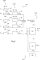
figure 2 , un logigramme illustrant le procédé selon l'invention.
- the
figure 1 , a diagram illustrating an aircraft according to the invention, and - the
figure 2 , a logic diagram illustrating the method according to the invention.
Les éléments présents dans plusieurs figures distinctes sont affectés d'une seule et même référence.The elements present in several separate figures are assigned a single reference.
La
Cet aéronef comporte au moins un rotor principal 2 pourvu d'une pluralité de pales 3. Le rotor principal participe au moins à la sustentation voire à la propulsion de l'aéronef 1.This aircraft comprises at least one
De plus, l'aéronef 1 peut comporter un rotor auxiliaire 4 muni de pales 5. Le rotor auxiliaire peut au moins participer au contrôle du mouvement en lacet de l'aéronef 1.In addition, the
Dès lors, le rotor principal 2 et le rotor auxiliaire 4 sont libres d'effectuer des rotations par rapport à la cellule de l'aéronef 1 respectivement autour de deux axes de rotation non parallèles. Le rotor principal 2 effectue par exemple une rotation autour d'un axe en élévation AX1, le rotor auxiliaire 4 effectuant une rotation autour d'un axe transversal AX2.Therefore, the
Pour engendrer la rotation du rotor principal 2 et la rotation du rotor auxiliaire 4, l'aéronef 1 comporte une installation motrice comprenant au moins un moteur 6. Le moteur 6 peut être relié mécaniquement au rotor principal 2 par une boîte de transmission principale 100 de puissance. En outre, le moteur 6 peut être relié mécaniquement au rotor auxiliaire 2 par la boîte de transmission principale 100 et /ou une boite de transmission auxiliaire de puissance non représentée.To generate the rotation of the
Le moteur 6 peut être par exemple un moteur thermique, ou un moteur électrique.The
Chaque moteur peut être régulé par un moyen de régulation et de contrôle 15 parfois connu sous l'acronyme « FADEC ». Le moyen de régulation et de contrôle 15 peut comporter un doseur de carburant dans le cadre d'un moteur thermique et une unité commandant le doseur de carburant en fonction de paramètres de surveillance du moteur voire de la boîte de transmission de puissance et de consignes.Each motor can be regulated by a control and control means 15 sometimes known by the acronym "FADEC". The control and control means 15 may comprise a fuel metering device in the context of a heat engine and a unit controlling the fuel metering device according to monitoring parameters of the engine or of the power transmission gearbox and setpoints.
Sur un turbomoteur, ces paramètres de surveillance peuvent inclure la vitesse de rotation Ng du générateur de gaz du turbomoteur mesurée par un capteur de vitesse 31, le couple moteur Q mesuré par un couplemètre 32 et une température mesurée par un capteur de température 33. Par exemple la température T4 ou T45 des gaz à l'entrée d'une turbine libre basse pression du turbomoteur est mesurée.On a turbine engine, these monitoring parameters can include the rotation speed Ng of the gas turbine engine of the turbine engine measured by a
Ces paramètres de surveillance peuvent aussi inclure un couple C exercé au sein de la boite de transmission principale, notamment sur un arbre de cette boite de transmission principale tel qu'un mât rotor .L'aéronef peut alors comporter un moyen de surveillance du couple C de la boite de transmission principale 100 mesuré par un couplemètre 320.These monitoring parameters may also include a torque C exerted within the main gearbox, in particular on a shaft of this main gearbox such as a rotor mast. The aircraft may then include a torque monitoring means C of the
On se référera à la littérature pour obtenir des informations complémentaires sur les paramètres de surveillance d'une installation motrice et leurs systèmes de mesure 30.Reference will be made to the literature for additional information on the monitoring parameters of a power plant and their
Par ailleurs, l'aéronef 1 comporte des moyens pour commander le pas des pales du rotor principal et des pales du rotor arrière. Ainsi, le pas collectif des pales 3 du rotor principal peut être contrôlé par un levier de pas collectif 7, le pas cyclique des pales 3 du rotor principal pouvant être contrôlé par un manche cyclique 8. Le pas collectif des pales 5 du rotor auxiliaire 4 peut être contrôlé par un organe de commande 9, tel qu'un palonnier par exemple.In addition, the
En outre, l'aéronef 1 comporte un dispositif d'aide au pilotage 10 selon l'invention.In addition, the
Ce dispositif d'aide au pilotage 10 est muni d'une unité de traitement 60 qui est configurée pour mettre en oeuvre le procédé selon l'inventionThis piloting
L'unité de traitement 60 peut comprendre par exemple un processeur, un circuit intégré, un système programmable, un circuit logique, ces exemples ne limitant pas la portée donnée à l'expression « unité de traitement ».The
Selon l'exemple de la
En outre, l'unité de traitement 60 possède une unité de stockage 62. Par exemple, l'unité de stockage 62 est munie d'une ou plusieurs mémoires éventuellement amovibles. Une telle mémoire peut prendre la forme d'un disque dur, d'une carte de mémoire amovible... L'unité de stockage 62 peut notamment posséder une mémoire non volatile 63 stockant des instructions exécutables par l'unité de calcul pour mettre en oeuvre des étapes du procédé de l'invention, voire une mémoire volatile 64 mémorisant des données mesurées, utiles à l'exécution dudit procédé.In addition, the
L'unité de traitement peut alors être reliée par une liaison filaire ou sans fil à divers systèmes de mesure et par exemple à : un système de mesure 20 mesurant un paramètre relatif au pas collectif des pales 3 du rotor principal 2 tel que par exemple la position d'un organe d'une chaîne de commande du pas collectif, un système de mesure 25 mesurant un paramètre relatif à une vitesse de rotation courante du rotor principal 2, un système de mesure 30 mesurant une valeur relative à chaque paramètre de surveillance, un système de mesure 35 mesurant une valeur relative à la température T0 de l'air ambiant présent à l'extérieur de l'aéronef 1, un système de mesure 40 mesurant une valeur relative à la pression P0 de l'air ambiant présent à l'extérieur de l'aéronef 1, un système de mesure 45 mesurant une valeur relative à une vitesse d'avancement IAS de l'aéronef 1, un système de mesure 50 mesurant une valeur relative à une position de l'organe de commande 9 commandant le pas des pales du rotor auxiliaire 4.The processing unit can then be connected by a wired or wireless connection to various measurement systems and for example to: a
Eventuellement, l'unité de traitement 60 peut communiquer avec un système de régulation 15 contrôlant un moteur 6, pour obtenir les valeurs courantes des paramètres de surveillance voire une marge de chaque paramètre de surveillance par rapport à au moins une limite ou encore une marge de puissance limitante.Optionally, the
Dès lors, l'unité de traitement peut mémoriser dans son unité de stockage les données provenant des systèmes de mesure. Cette unité de traitement exécute alors les étapes du procédé selon l'invention pour obtenir au moins une limite de pas collectif du rotor principal, voire une limite de pas collectif du rotor principal pour au moins deux régimes de fonctionnement du moteur 6.Therefore, the processing unit can store in its storage unit the data from the measurement systems. This processing unit then executes the steps of the method according to the invention to obtain at least a collective pitch limit of the main rotor, or even a collective pitch limit of the main rotor for at least two operating speeds of the
En outre, l'unité de traitement est reliée par une liaison filaire ou sans fil à un afficheur 70 pour afficher chaque limite de pas collectif sur cet afficheur.In addition, the processing unit is connected by a wired or wireless link to a
Dès lors, l'afficheur 70 peut posséder un écran présentant une échelle en équivalent de pas collectif qui défile devant un index 71. L'index 71 pointe alors l'échelle pour signaler à un pilote une valeur du pas collectif courant des pales du rotor principal. De plus, au moins un symbole 72 représentant une limite de pas collectif est affiché.Therefore, the
La symbologie du document
La
Durant une première phase PH1, le dispositif d'aide au pilotage détermine une marge de puissance limitante ΔWlim de l'installation motrice 6.During a first phase PH1, the piloting aid device determines a limiting power margin ΔWlim of the
Cette marge de puissance limitante ΔWlim peut être déterminée par le moyen de régulation et de contrôle 15 des moteur 6, puis transmise à l'unité de traitement 60.This limiting power margin ΔWlim can be determined by the control and control means 15 of the
Selon une autre variante et durant une première étape STP1 de la première phase PH1, l'unité de traitement détermine une marge dite « marge individuelle ΔNg, Δt4, ΔQ, ΔC » pour respectivement chaque paramètre de surveillance Ng, T4, Q, C.According to another variant and for a first step STP1 of the first phase PH1, the processing unit determines a so-called margin "individual margin Δ Ng, Δ t4, Δ Q Δ C" respectively for each monitoring parameter Ng, T4, Q, C.
Par exemple, l'unité de traitement applique un modèle mathématique 101 du moteur pour déterminer une limite de la vitesse de rotation du générateur de gaz Nglim, par exemple en fonction d'un prélèvement de gaz P2 effectué sur le moteur, d'une pression extérieure P0 et d'une température extérieure T0. L'unité de traitement effectue alors une différence 102 de cette limite de la vitesse de rotation du générateur de gaz Nglim et de la vitesse de rotation courante du générateur de gaz Ng pour obtenir une première marge individuelle ΔNg de la vitesse de rotation du générateur de gaz.For example, the processing unit applies a
Le modèle mathématique du moteur peut en outre fournir une limite de température T4lim du moteur et une limite de couple Qlim. L'unité de traitement effectue alors une différence 104 de cette limite de température T4lim et de la température courante T4 pour obtenir une deuxième marge individuelle Δt4 de température. De même, l'unité de traitement effectue une différence 106 de cette limite de couple Qlim et du couple courant Q du moteur pour obtenir une troisième marge individuelle ΔQ de couple. Eventuellement, l'unité de traitement effectue une différence 1060 de la limite de couple Clim et du couple courant C de la boîte de transmission de puissance pour obtenir une quatrième marge individuelle ΔC de couple.The mathematical model of the engine may further provide a motor T4lim temperature limit and a Qlim torque limit. The processing unit then makes a
Durant une deuxième étape STP2 de la première phase PH1, l'unité de traitement transforme chaque marge individuelle ΔNg, Δt4, ΔQ, ΔC en une marge de puissance respective du moteur dite « marge de puissance individuelle ΔWNg,ΔWt4,ΔWQ, ΔWC » en appliquant des modèles mathématiques usuels.During a second step STP2 of the first phase PH1, the processing unit transforms each individual margin Δ Ng,
Par exemple et durant une première opération 103, l'unité de traitement transforme la première marge individuelle ΔNg en une première marge de puissance individuelle ΔWNg en fonction notamment de la pression extérieure P0 ainsi que de la température extérieure T0 et de la vitesse de rotation Nr du rotor principal.For example, during a
Durant une deuxième opération 105, l'unité de traitement peut transformer la deuxième marge individuelle Δt4 en une deuxième marge de puissance individuelle ΔWt4 en fonction notamment de la pression extérieure P0 ainsi que de la température extérieure T0 et de la vitesse de rotation Nr du rotor principal.During a
Durant une troisième opération 107, l'unité de traitement peut transformer la troisième marge individuelle ΔQ en une troisième marge de puissance individuelle ΔWQ en fonction notamment de la vitesse de rotation Nr du rotor principal.During a
Eventuellement, durant une quatrième opération 1070, l'unité de traitement peut transformer la quatrième marge individuelle ΔC en une quatrième marge de puissance individuelle ΔWC en fonction notamment de la vitesse de rotation Nr du rotor principal.Optionally, during a
Par suite et durant une troisième étape STP3 de la première phase PH1, l'unité de traitement détermine la marge de puissance limitante ΔWlim. La marge de puissance limitante ΔWlim est égale à la marge de puissance individuelle la plus faible. Selon l'exemple de la
Durant une deuxième phase PH2, l'unité de traitement 60 transforme la marge de puissance limitante ΔWlim en une marge de pas collectif Δθn représentant la marge entre un pas collectif courant θn des pales du rotor principal et une limite de pas collectif θlimit. During a second phase PH2, the
Durant une première étape 109 optionnelle de la deuxième phase PH2, l'unité de traitement 60 réduit la marge de puissance limitante ΔWlim selon un pourcentage prédéterminé si la vitesse de rotation Nr du rotor principal 2 diminue à une vitesse prédéterminée pendant un temps prédéterminé.During an optional
La réduction opérée peut être temporaire. Par exemple, le pourcentage de réduction appliqué à la marge de puissance limitante ΔWlim décroit d'un maximum à une valeur nulle sur une période prédéterminée. Par exemple, ce pourcentage décroit de 25% à zéro en deux secondes.The reduction made can be temporary. For example, the reduction percentage applied to the limiting power margin ΔWlim decreases from a maximum to a zero value over a predetermined period. For example, this percentage decreases from 25% to zero in two seconds.
Durant une deuxième étape 110 de la deuxième phase PH2, l'unité de traitement détermine à chaque instant de calcul courant n une marge de pas collectif Δθn des pales du rotor principal.During a
A cet effet, l'unité de traitement applique un algorithme minorant la marge de pas collectif Δθn par rapport à la marge de pas collectif réelle proportionnelle à la marge de puissance limitante ΔWlim lorsque la marge de puissance est non nulle pour anticiper un dépassement de ladite consigne induit par ledit moyen de régulation. La marge de pas collectif Δθn est nulle lorsque la marge puissance limitante ΔWlim est nulle.For this purpose, the processing unit applies an algorithm that reduces the collective pitch margin Δθn with respect to the real collective pitch margin proportional to the limiting power margin Δθlim when the power margin is non-zero in order to anticipate exceeding said power margin. setpoint induced by said regulating means. The collective pitch margin Δθn is zero when the limiting power margin ΔWlim is zero.
L'unité de traitement applique par exemple un algorithme récursif à l'aide d'une relation principale fournissant à chaque instant de calcul courant la marge de pas collectif Δθn. En particulier, la relation principale exprime la marge de pas collectif Δθn en fonction du quotient de la marge de puissance limitante ΔWlim et d'un dénominateur, ce dénominateur étant égal au produit d'un premier terme A1 et d'un deuxième terme A2. Le premier terme A1 est en outre fonction du pas collectif courant θn des pales du rotor principal et de la limite de pas collectif ![]()
![]()
La relation principale prend alors la forme suivante : 
A la première itération réalisée au démarrage de l'aéronef, la limite de pas collectif ![]()
![]()
Plus précisément, le premier terme peut prendre la forme suivante : ![]()
![]()
![]()
![]()
En outre, le deuxième terme peut prendre la forme suivante : ![]()
![]()
Par suite, la relation principale appliquée par l'unité de traitement peut prendre la forme suivante : 
Le coefficient B peut être déterminé par essai par le constructeur pour minorer en permanence la marge de pas collectif calculée par rapport à la marge de pas collectif réelle.The coefficient B may be determined by testing by the manufacturer to permanently reduce the calculated collective margin over the actual collective margin.
Par suite, le coefficient B peut être une variable qui varie en fonction de la vitesse d'avancement IAS de l'aéronef 1.As a result, the coefficient B may be a variable that varies according to the speed of advance IAS of the
Durant une première étape 111 de la troisième phase PH3, l'unité de traitement 60 détermine à chaque instant de calcul la limite de pas collectif θlimit des pales du rotor principal. Cette limite de pas collectif θlimit est égale à la somme de la marge de pas collectif des pales du rotor principal et du pas collectif courant des pales du rotor principal.During a
Durant une deuxième étape 112, l'unité de traitement requiert l'affichage du pas collectif courant et de la limite de pas collectif θlimit. During a
Eventuellement, durant la première étape 111 de la troisième phase PH3, l'unité de traitement comporte une étape de filtrage. L'unité de traitement détermine alors la limite de pas collectif des pales du rotor principal à afficher à un instant de calcul courant en appliquant le filtre suivant : ![]()
![]()
![]()
![]()
![]()
![]()
Dès lors, la valeur de la limite de pas collectif des pales du rotor principal à l'issue de l'étape de filtrage est réutilisée durant la deuxième étape 110 de la deuxième phase PH2 et la première étape 111 de la troisième phase PH3 réalisée à l'instant de calcul de suivant.Therefore, the value of the collective pitch limit of the main rotor blades at the end of the filtering step is reused during the
Par ailleurs la constante de filtrage f peut être déterminée par exemple par essais, et peut varier en fonction de la phase de vol.Moreover, the filter constant f can be determined for example by tests, and can vary according to the flight phase.
Eventuellement, l'unité de traitement détermine la valeur de la constante de filtrage en fonction d'une valeur d'une variable dite « variable d'un organe de commande Fpal ». Cette variable d'un organe de commande Fpal est fonction d'une vitesse de déplacement de l'organe de commande 9 qui commande le pas des pales 5 du rotor auxiliaire 4. Par exemple, une relation prédéterminée ou un tableau de valeurs donne la valeur de la variable d'un organe de commande Fpal en fonction de la vitesse de déplacement de l'organe de commande 9.Optionally, the processing unit determines the value of the filtering constant as a function of a value of a variable called "variable of a Fpal controller". This variable of a control device Fpal is a function of a speed of movement of the
De manière alternative ou complémentaire, l'unité de traitement 60 détermine la valeur de la constante de filtrage f en fonction d'une valeur d'une variable dite « variable d'avancement Fvit ». Cette variable d'avancement Fvit est en outre fonction d'une vitesse d'avancement IAS de l'aéronef 1. Par exemple, une relation prédéterminée ou un tableau de valeurs donne la valeur de la variable d'avancement Fvit en fonction de la vitesse d'avancement IAS.Alternatively or additionally, the
Le cas échéant, la valeur de la constante de filtrage est égale au produit d'une constante prédéterminée et du maximum entre la variable d'avancement Fvit et la variable d'un organe de commande Fpal.If necessary, the value of the filtering constant is equal to the product of a predetermined constant and the maximum between the feed variable Fvit and the variable of a control device Fpal.
Par ailleurs, l'unité de traitement 60 peut geler la limite de pas collectif en la maintenant égale à la valeur de cette limite de pas collectif au pas de calcul précédent. En particulier, l'unité de traitement peut geler la limite de pas collectif lors d'une phase de vol agressive prédéterminée de l'aéronef 1.Moreover, the
Une phase de vol peut être considérée comme étant une phase de vol agressive :
- si le pas collectif des pales 3 du
rotor principal 2 varie à une vitesse supérieure à un seuil de variation de vitesse haut K1 prédéterminé, ou - si le pas collectif des pales 3 du
rotor principal 2 varie à une vitesse comprise entre un seuil de variation de vitesse bas K0 prédéterminé et ledit seuil de variation de vitesse haut K1 pendant un seuil de durée, ou - si la variation de la vitesse de rotation dudit rotor principal est supérieure à un seuil bas K2 et si l'organe de commande 9 commandant le pas de pales 5 du rotor auxiliaire 4 n'est pas manoeuvré, ou
- si la variation de la vitesse de rotation dudit rotor principal est supérieure à un seuil haut K3 et si l'organe de commande 9 est manoeuvré.
- if the collective pitch of the
blades 3 of themain rotor 2 varies at a speed greater than a predetermined high speed variation threshold K1, or - if the collective pitch of the
blades 3 of themain rotor 2 varies at a speed between a predetermined low speed variation threshold K0 and said high speed variation threshold K1 during a duration threshold, or - if the variation of the rotational speed of said main rotor is greater than a low threshold K2 and if the
control member 9 controlling the pitch of theblades 5 of theauxiliary rotor 4 is not maneuvered, or - if the variation of the rotation speed of said main rotor is greater than a high threshold K3 and if the
control member 9 is maneuvered.
L'unité de traitement peut néanmoins inhiber l'étape de gel si la position de l'organe de commande 9 commandant le pas de pales 5 d'un rotor auxiliaire 4 varie à une vitesse de déplacement supérieure à un seuil de vitesse de déplacement.The processing unit may nevertheless inhibit the freezing step if the position of the
Par contre, l'étape de gel n'est éventuellement pas inhibée si la position de l'organe de commande 9 commandant le pas de pales 5 d'un rotor auxiliaire 4 varie à une vitesse de déplacement supérieure à un seuil de déplacement et si le pas collectif des pales 3 du rotor principal 2 varie à une vitesse supérieure à un seuil de variation de vitesse haut prédéterminé. Dans cette phase de vol très agressive, le gel de la limite ne peut pas être interdit.On the other hand, the gel step may not be inhibited if the position of the
L'étape de gel peut être réalisée en maintenant constante la marge de puissance limitante ou la marge de pas collectif par exemple.The gel step can be performed by keeping the limiting power margin or the collective pitch margin constant, for example.
Selon l'exemple de la
La valeur de la constante de filtrage f peut alors varier lors d'une phase de vol agressive et/ ou en fonction de la valeur de la variable d'un organe de commande Fpal voire de la valeur de la variable d'avancement FvitThe value of the filter constant f may then vary during an aggressive flight phase and / or as a function of the value of the variable of a control device Fpal or even of the value of the feed variable Fvit
En outre, lors du passage d'une phase de vol dite « phase de vol agressive » à une phase de vol stabilisée, la constante de filtrage peut être modifiée. Par exemple, cette constante de filtrage peut être modifiée pour être égale, pendant une durée déterminée de transition, à la constante de filtrage à appliquer en phase de vol stabilisée divisée par quatre.In addition, during the transition from a phase of flight called "aggressive flight phase" to a stabilized flight phase, the filter constant can be changed. For example, this filter constant can be modified to be equal, during a determined transition period, to the filtering constant to be applied in the stabilized flight phase divided by four.
L'expression « phase de vol stabilisé » désigne toutes les phases de vol qui ne sont pas considérées comme étant agressives.The term "stabilized flight phase" refers to all phases of flight that are not considered aggressive.
Naturellement, la présente invention est sujette à de nombreuses variations quant à sa mise en oeuvre. Bien que plusieurs modes de réalisation aient été décrits, on comprend bien qu'il n'est pas concevable d'identifier de manière exhaustive tous les modes possibles. Il est bien sûr envisageable de remplacer un moyen décrit par un moyen équivalent sans sortir du cadre de la présente invention.Naturally, the present invention is subject to many variations as to its implementation. Although several embodiments have been described, it is well understood that it is not conceivable to exhaustively identify all the possible modes. It is of course conceivable to replace a means described by equivalent means without departing from the scope of the present invention.
La
Toutefois, ce procédé peut être mis en oeuvre en appliquant des logigrammes alternatifs. Par exemple, un tel logigramme alternatif pourrait comprendre deux branches distinctes, une branche comprenant les étapes à mettre en oeuvre lors d'une phase de vol stabilisé, et une autre branche comprenant les étapes à mettre en oeuvre lors d'une phase de vol dynamique. Par exemple, un test pour être réalisée à l'issue de la détermination de la marge de puissance limitante pour déterminer la branche à utiliser.However, this method can be implemented by applying alternative logigrams. For example, such an alternative logic diagram could comprise two distinct branches, one branch comprising the steps to be implemented during a stabilized flight phase, and another branch comprising the steps to be implemented during a dynamic flight phase. . For example, a test to be performed after determining the limiting power margin to determine the branch to use.
Claims (21)
caractérisé en ce que ledit algorithme est un algorithme récursif utilisant une relation principale fournissant à chaque instant de calcul courant ladite marge de pas collectif (Δθ) en fonction d'un quotient de ladite marge de puissance limitante (ΔWlim) et d'un dénominateur, ledit dénominateur étant égal au produit d'un premier terme (A1) et d'un deuxième terme (A2), le premier terme (A1) étant fonction du pas collectif courant (θn ) desdites pales audit instant de calcul courant (n) et d'une la limite de pas collectif
characterized in that said algorithm is a recursive algorithm using a main relationship providing at each current computation time said collective pitch margin (Δθ) as a function of a quotient of said limiting power margin (ΔWlim) and a denominator, said denominator being equal to the product of a first term (A1) and a second term (A2), the first term (A1) being a function of the current collective pitch ( θ n ) of said blades at said current calculation instant (n) and a collective step limit
caractérisé en ce que pour déterminer la marge de puissance limitante (ΔWlim), ledit procédé comporte les étapes suivantes :
characterized in that to determine the limiting power margin (ΔWlim), said method comprises the following steps:
caractérisé en ce que ledit premier terme est déterminé à l'aide de la relation suivante :
characterized in that said first term is determined using the following relationship:
caractérisé en ce que ledit deuxième terme est déterminé à l'aide de la relation suivante :
characterized in that said second term is determined using the following relationship:
caractérisé en ce que ledit coefficient (B) est une variable qui varie en fonction de la vitesse d'avancement (IAS) de l'aéronef (1).Piloting aid method according to one of Claims 2 to 5,
characterized in that said coefficient (B) is a variable that varies as a function of the forward speed (IAS) of the aircraft (1).
caractérisé en ce que ledit pourcentage décroit d'un maximum à une valeur nulle sur une période prédéterminée.Process according to claim 7,
characterized in that said percentage decreases from a maximum to a zero value over a predetermined period.
caractérisé en ce que lors d'une phase de vol agressive prédéterminée de l'aéronef (1), le procédé comporte une étape de gel durant laquelle la limite de pas collectif est maintenue égale à la valeur de cette limite de pas collectif atteinte avant ladite phase de vol agressive.Process according to any one of claims 1 to 8,
characterized in that during a predetermined aggressive flight phase of the aircraft (1), the method comprises a gel step during which the collective pitch limit is maintained equal to the value of this collective pitch limit reached before said aggressive flight phase.
caractérisé en ce qu'une phase de vol agressive est détectée :
characterized in that an aggressive flight phase is detected:
caractérisé en ce que ladite étape de gel est inhibée si une position d'un organe de commande (9) commandant le pas de pales (5) d'un rotor auxiliaire (4) varie à une vitesse de déplacement supérieure à un seuil de vitesse de déplacement.Process according to claim 9,
characterized in that said gel step is inhibited if a position of a control member (9) controlling the pitch of blades (5) of an auxiliary rotor (4) varies at a movement speed greater than a speed threshold of displacement.
caractérisé en ce que ladite étape de gel n'est pas inhibée si une position d'un organe de commande (9) commandant le pas de pales (5) d'un rotor auxiliaire (4) varie à une vitesse de déplacement supérieure à un seuil de déplacement et si le pas collectif des pales (3) du rotor principal (2) varie à une vitesse supérieure à un seuil de variation de vitesse haut prédéterminéProcess according to claim 11,
characterized in that said gel step is not inhibited if a position of a control member (9) controlling the blade pitch (5) of an auxiliary rotor (4) varies at a movement speed greater than one displacement threshold and if the collective pitch of the blades (3) of the main rotor (2) varies at a speed greater than a predetermined high speed variation threshold
caractérisé en ce que préalablement à l'affichage de la limite de pas collectif, ledit procédé comporte une étape de filtrage, la limite de pas collectif étant déterminée à un instant de calcul courant en appliquant le filtre suivant :
characterized in that prior to the display of the collective pitch limit, said method comprises a filtering step, the collective pitch limit being determined at a current computation time by applying the following filter:
caractérisé en ce que l'étape de gel est réalisée en conférant à ladite constante de filtrage une valeur nulle.Process according to claim 9 and claim 13,
characterized in that the gel step is performed by conferring on said filter constant a zero value.
Caractérisé en ce que lors du passage d'une phase de vol dite agressive à une phase de vol stabilisée prédéterminée de l'aéronef (1), ledit filtre est appliqué, pendant une durée prédéterminée, avec une constante de filtrage égale à une constante de filtrage prédéterminée à appliquer durant la phase de vol stabilisée divisée par quatre.Process according to claim 13,
Characterized in that during the transition from a so-called aggressive flight phase to a predetermined stabilized flight phase of the aircraft (1), said filter is applied, for a predetermined duration, with a filter constant equal to a constant of predetermined filtering to be applied during the stabilized flight phase divided by four.
caractérisé en ce que la valeur de la constante de filtrage est fonction d'une valeur d'une variable dite « variable d'un organe de commande (Fpal) », la variable d'un organe de commande (Fpal) variant en fonction d'une vitesse de déplacement d'un organe de commande (9) commandant le pas de pales (5) d'un rotor auxiliaire (4).Process according to any one of claims 13 to 15,
characterized in that the value of the filtering constant is a function of a value of a variable called "variable of a control member (Fpal)", the variable of a control member (Fpal) varying according to a speed of movement of a control member (9) controlling the pitch of blades (5) of an auxiliary rotor (4).
caractérisé en ce que la valeur de la constante de filtrage (f) est fonction d'une valeur d'une variable dite « variable d'avancement (Fvit) », la variable d'avancement (Fvit) variant en fonction d'une vitesse d'avancement (IAS) de l'aéronef (1).Process according to any one of claims 13 to 16,
characterized in that the value of the filtering constant (f) is a function of a value of a variable called "variable of progress (Fvit) ", the variable of advancement (Fvit) varying according to a speed of advance (IAS) of the aircraft (1).
caractérisé en ce que la valeur de la constante de filtrage est égale au produit d'une constante prédéterminée et du maximum entre la variable d'avancement (Fvit) et la variable d'un organe de commande (Fpal).Process according to Claim 16 and Claim 17,
characterized in that the value of the filter constant is equal to the product of a predetermined constant and the maximum between the feed variable (Fvit) and the variable of a control member (Fpal).
caractérisé en ce que ledit dispositif d'aide au pilotage (10) comporte une unité de traitement (60) configurée pour appliquer le procédé selon l'une quelconque des revendications 1 à 18.Driver assistance device comprising a display (70) displaying a collective pitch limit,
characterized in that said driver assist device (10) comprises a processing unit (60) configured to apply the method of any one of claims 1 to 18.
caractérisé en ce que ledit dispositif d'aide au pilotage (10) comporte au moins un des organes suivants :
characterized in that said piloting aid device (10) comprises at least one of the following organs:
caractérisé en ce que ledit aéronef (1) étant un giravion qui comporte un dispositif d'aide au pilotage (10) selon l'une quelconque des revendications 19 à 20.Aircraft (1) equipped with a powerplant comprising at least one engine (6) and a main rotor (2) participating at least partially in the lift and / or propulsion of the aircraft (1),
characterized in that said aircraft (1) is a rotorcraft which includes a flight aid device (10) according to any one of claims 19 to 20.
Priority Applications (1)
| Application Number | Priority Date | Filing Date | Title |
|---|---|---|---|
| PL17165759T PL3251955T3 (en) | 2016-05-30 | 2017-04-10 | A method and a device for assisting the piloting of an aircraft, and an aircraft |
Applications Claiming Priority (1)
| Application Number | Priority Date | Filing Date | Title |
|---|---|---|---|
| FR1600871A FR3051772B1 (en) | 2016-05-30 | 2016-05-30 | METHOD, DEVICE FOR AIDING THE CONTROL OF AN AIRCRAFT, AND AIRCRAFT |
Publications (2)
| Publication Number | Publication Date |
|---|---|
| EP3251955A1 true EP3251955A1 (en) | 2017-12-06 |
| EP3251955B1 EP3251955B1 (en) | 2018-09-26 |
Family
ID=56322010
Family Applications (1)
| Application Number | Title | Priority Date | Filing Date |
|---|---|---|---|
| EP17165759.6A Active EP3251955B1 (en) | 2016-05-30 | 2017-04-10 | A method and a device for assisting the piloting of an aircraft, and an aircraft |
Country Status (4)
| Country | Link |
|---|---|
| US (1) | US10252813B2 (en) |
| EP (1) | EP3251955B1 (en) |
| FR (1) | FR3051772B1 (en) |
| PL (1) | PL3251955T3 (en) |
Families Citing this family (4)
| Publication number | Priority date | Publication date | Assignee | Title |
|---|---|---|---|---|
| FR3082504B1 (en) * | 2018-06-14 | 2021-03-05 | Airbus Helicopters | METHOD AND DEVICE FOR LIMITING TORQUE ON A GIRAVION INCLUDING AT LEAST THREE ENGINES NOT EQUIPPED WITH POWER |
| US11299286B2 (en) | 2019-05-15 | 2022-04-12 | Pratt & Whitney Canada Corp. | System and method for operating a multi-engine aircraft |
| US20220169397A1 (en) * | 2020-11-30 | 2022-06-02 | Bell Textron Inc. | Modeling and integrating engine installation deltas |
| FR3134564A1 (en) | 2022-04-15 | 2023-10-20 | Airbus Helicopters | Method and system for assisting in piloting an aircraft, aircraft equipped with such a system. |
Citations (6)
| Publication number | Priority date | Publication date | Assignee | Title |
|---|---|---|---|---|
| FR2749545A1 (en) | 1996-06-07 | 1997-12-12 | Eurocopter France | STEERING INDICATOR FOR AIRCRAFT |
| FR2756256A1 (en) | 1996-11-26 | 1998-05-29 | Eurocopter France | Power margin indicator for helicopters |
| FR2802982A1 (en) | 1999-12-22 | 2001-06-29 | Oreal | DEVICE FOR RECHARGING COMPRESSED AIR IN A CONTAINER |
| FR2809082A1 (en) * | 2000-05-17 | 2001-11-23 | Eurocopter France | Power margin indicator for a rotary wing aircraft, e.g. a helicopter, having a display to indicate when correcting action must be taken |
| FR2973340A1 (en) | 2011-03-30 | 2012-10-05 | Eurocopter France | METHOD, DEVICE FOR AIDING THE CONTROL OF AN AIRCRAFT, AND AIRCRAFT |
| EP2518582A1 (en) | 2011-04-29 | 2012-10-31 | Eurocopter | Passage from a state of non-synchronisation to a state of synchronisation between a motor and a rotor |
Family Cites Families (4)
| Publication number | Priority date | Publication date | Assignee | Title |
|---|---|---|---|---|
| US3744928A (en) * | 1971-10-07 | 1973-07-10 | United Aircraft Corp | Rotor overload protection |
| US6735500B2 (en) * | 2002-06-10 | 2004-05-11 | The Boeing Company | Method, system, and computer program product for tactile cueing flight control |
| US7212942B2 (en) * | 2003-06-10 | 2007-05-01 | Precision Innovations Llc | Power available and limitation indicator for use with an aircraft engine |
| FR2946322B1 (en) * | 2009-06-04 | 2011-06-17 | Eurocopter France | HYBRID HELICOPTER ASSISTING DEVICE, HYBRID HELICOPTER PROVIDED WITH SUCH A DEVICE AND METHOD USED THEREBY |
-
2016
- 2016-05-30 FR FR1600871A patent/FR3051772B1/en not_active Expired - Fee Related
-
2017
- 2017-04-10 EP EP17165759.6A patent/EP3251955B1/en active Active
- 2017-04-10 PL PL17165759T patent/PL3251955T3/en unknown
- 2017-05-30 US US15/607,939 patent/US10252813B2/en active Active
Patent Citations (6)
| Publication number | Priority date | Publication date | Assignee | Title |
|---|---|---|---|---|
| FR2749545A1 (en) | 1996-06-07 | 1997-12-12 | Eurocopter France | STEERING INDICATOR FOR AIRCRAFT |
| FR2756256A1 (en) | 1996-11-26 | 1998-05-29 | Eurocopter France | Power margin indicator for helicopters |
| FR2802982A1 (en) | 1999-12-22 | 2001-06-29 | Oreal | DEVICE FOR RECHARGING COMPRESSED AIR IN A CONTAINER |
| FR2809082A1 (en) * | 2000-05-17 | 2001-11-23 | Eurocopter France | Power margin indicator for a rotary wing aircraft, e.g. a helicopter, having a display to indicate when correcting action must be taken |
| FR2973340A1 (en) | 2011-03-30 | 2012-10-05 | Eurocopter France | METHOD, DEVICE FOR AIDING THE CONTROL OF AN AIRCRAFT, AND AIRCRAFT |
| EP2518582A1 (en) | 2011-04-29 | 2012-10-31 | Eurocopter | Passage from a state of non-synchronisation to a state of synchronisation between a motor and a rotor |
Also Published As
| Publication number | Publication date |
|---|---|
| PL3251955T3 (en) | 2019-02-28 |
| FR3051772B1 (en) | 2019-08-23 |
| US10252813B2 (en) | 2019-04-09 |
| EP3251955B1 (en) | 2018-09-26 |
| FR3051772A1 (en) | 2017-12-01 |
| US20170341771A1 (en) | 2017-11-30 |
Similar Documents
| Publication | Publication Date | Title |
|---|---|---|
| EP2505502B1 (en) | Method and device to assist piloting of an aircraft, and aircraft | |
| EP3251955B1 (en) | A method and a device for assisting the piloting of an aircraft, and an aircraft | |
| EP3050806B1 (en) | A device for monitoring a power transmission system of an aircraft, an aircraft provided with the device, and the method used | |
| CA2590991C (en) | Power balancing of two aircraft turboshaft engine | |
| EP1993908B1 (en) | Method and device for controlling the thrust of a multi-engine aircraft | |
| EP3064437B1 (en) | A method and a device for determining and optimizing parameters that are characteristic of the operation of a rotary wing aircraft | |
| EP3098579B1 (en) | A method of estimating the instantaneous mass of a rotary wing aircraft | |
| EP3597536B1 (en) | Method and device for predictive determination of characteristic parameters of the operation of a rotary-wing aircraft for the performance of a predetermined manoeuvre | |
| FR2900385A1 (en) | Rotorcraft/helicopter steering assistance method, involves determining pitch control adapted such that rotorcraft accelerates along profile which varies according to time and engine functioning state | |
| EP3179328B1 (en) | A method and a device for piloting an aircraft | |
| FR2902407A1 (en) | Limited value determining method for rotorcraft, involves determining apparent difference between current value and limited value of monitoring parameters, and determining limited margin by subtracting useful comfort margin from difference | |
| FR3031729A1 (en) | POWER CONTROL FOR AIRCRAFT AIRCRAFT | |
| FR2958050A1 (en) | METHOD AND SYSTEM FOR MANAGING THE ENERGY VARIATION OF AN AIRCRAFT | |
| EP3338147B1 (en) | System for controlling a controlled parameter | |
| WO2007010118A1 (en) | Indicator for piloting an aircraft, designed to provide a power parameter of at least one turboprop engine of said aircraft | |
| EP3753844A1 (en) | Control handle and hybrid rotorcraft provided with a lift rotor and at least one propulsion rotor generating thrust | |
| FR2871520A1 (en) | STEERING INDICATOR FOR PREDICTING THE EVOLUTION OF THE MONITORING PARAMETERS OF A TURBOMOTEUR | |
| FR3097527A1 (en) | Method of assisting in piloting a hybrid rotorcraft equipped with a lift rotor and at least one propellant rotor with propeller generating thrust | |
| EP3647192B1 (en) | Method and device for assisted piloting of a hybrid rotorcraft provided with a lift rotor and at least one propulsion rotor generating thrust | |
| CA3102691C (en) | Device for monitoring a buoyancy margin for rotocraft, associated rotocraft and corresponding method | |
| EP3263462B1 (en) | A power margin indicator device for a rotorcraft, an associated rotorcraft and a corresponding method | |
| EP3882132A1 (en) | Method for protecting the torque and/or thrust of propellers of a hybrid helicopter and hybrid helicopter | |
| FR3129919A1 (en) | Device for assisting the regulation of aeronautical turbomachinery propellers |
Legal Events
| Date | Code | Title | Description |
|---|---|---|---|
| PUAI | Public reference made under article 153(3) epc to a published international application that has entered the european phase |
Free format text: ORIGINAL CODE: 0009012 |
|
| STAA | Information on the status of an ep patent application or granted ep patent |
Free format text: STATUS: THE APPLICATION HAS BEEN PUBLISHED |
|
| AK | Designated contracting states |
Kind code of ref document: A1 Designated state(s): AL AT BE BG CH CY CZ DE DK EE ES FI FR GB GR HR HU IE IS IT LI LT LU LV MC MK MT NL NO PL PT RO RS SE SI SK SM TR |
|
| AX | Request for extension of the european patent |
Extension state: BA ME |
|
| STAA | Information on the status of an ep patent application or granted ep patent |
Free format text: STATUS: REQUEST FOR EXAMINATION WAS MADE |
|
| 17P | Request for examination filed |
Effective date: 20171215 |
|
| RBV | Designated contracting states (corrected) |
Designated state(s): AL AT BE BG CH CY CZ DE DK EE ES FI FR GB GR HR HU IE IS IT LI LT LU LV MC MK MT NL NO PL PT RO RS SE SI SK SM TR |
|
| GRAP | Despatch of communication of intention to grant a patent |
Free format text: ORIGINAL CODE: EPIDOSNIGR1 |
|
| RIC1 | Information provided on ipc code assigned before grant |
Ipc: B64D 43/00 20060101AFI20180529BHEP Ipc: B64C 27/04 20060101ALI20180529BHEP |
|
| STAA | Information on the status of an ep patent application or granted ep patent |
Free format text: STATUS: GRANT OF PATENT IS INTENDED |
|
| INTG | Intention to grant announced |
Effective date: 20180705 |
|
| GRAS | Grant fee paid |
Free format text: ORIGINAL CODE: EPIDOSNIGR3 |
|
| GRAA | (expected) grant |
Free format text: ORIGINAL CODE: 0009210 |
|
| STAA | Information on the status of an ep patent application or granted ep patent |
Free format text: STATUS: THE PATENT HAS BEEN GRANTED |
|
| AK | Designated contracting states |
Kind code of ref document: B1 Designated state(s): AL AT BE BG CH CY CZ DE DK EE ES FI FR GB GR HR HU IE IS IT LI LT LU LV MC MK MT NL NO PL PT RO RS SE SI SK SM TR |
|
| REG | Reference to a national code |
Ref country code: GB Ref legal event code: FG4D Free format text: NOT ENGLISH |
|
| REG | Reference to a national code |
Ref country code: CH Ref legal event code: EP |
|
| REG | Reference to a national code |
Ref country code: AT Ref legal event code: REF Ref document number: 1045709 Country of ref document: AT Kind code of ref document: T Effective date: 20181015 |
|
| REG | Reference to a national code |
Ref country code: IE Ref legal event code: FG4D Free format text: LANGUAGE OF EP DOCUMENT: FRENCH |
|
| REG | Reference to a national code |
Ref country code: DE Ref legal event code: R096 Ref document number: 602017000513 Country of ref document: DE |
|
| REG | Reference to a national code |
Ref country code: NL Ref legal event code: MP Effective date: 20180926 |
|
| PG25 | Lapsed in a contracting state [announced via postgrant information from national office to epo] |
Ref country code: BG Free format text: LAPSE BECAUSE OF FAILURE TO SUBMIT A TRANSLATION OF THE DESCRIPTION OR TO PAY THE FEE WITHIN THE PRESCRIBED TIME-LIMIT Effective date: 20181226 Ref country code: NO Free format text: LAPSE BECAUSE OF FAILURE TO SUBMIT A TRANSLATION OF THE DESCRIPTION OR TO PAY THE FEE WITHIN THE PRESCRIBED TIME-LIMIT Effective date: 20181226 Ref country code: GR Free format text: LAPSE BECAUSE OF FAILURE TO SUBMIT A TRANSLATION OF THE DESCRIPTION OR TO PAY THE FEE WITHIN THE PRESCRIBED TIME-LIMIT Effective date: 20181227 Ref country code: LT Free format text: LAPSE BECAUSE OF FAILURE TO SUBMIT A TRANSLATION OF THE DESCRIPTION OR TO PAY THE FEE WITHIN THE PRESCRIBED TIME-LIMIT Effective date: 20180926 Ref country code: RS Free format text: LAPSE BECAUSE OF FAILURE TO SUBMIT A TRANSLATION OF THE DESCRIPTION OR TO PAY THE FEE WITHIN THE PRESCRIBED TIME-LIMIT Effective date: 20180926 Ref country code: FI Free format text: LAPSE BECAUSE OF FAILURE TO SUBMIT A TRANSLATION OF THE DESCRIPTION OR TO PAY THE FEE WITHIN THE PRESCRIBED TIME-LIMIT Effective date: 20180926 |
|
| REG | Reference to a national code |
Ref country code: LT Ref legal event code: MG4D |
|
| PG25 | Lapsed in a contracting state [announced via postgrant information from national office to epo] |
Ref country code: LV Free format text: LAPSE BECAUSE OF FAILURE TO SUBMIT A TRANSLATION OF THE DESCRIPTION OR TO PAY THE FEE WITHIN THE PRESCRIBED TIME-LIMIT Effective date: 20180926 Ref country code: AL Free format text: LAPSE BECAUSE OF FAILURE TO SUBMIT A TRANSLATION OF THE DESCRIPTION OR TO PAY THE FEE WITHIN THE PRESCRIBED TIME-LIMIT Effective date: 20180926 Ref country code: HR Free format text: LAPSE BECAUSE OF FAILURE TO SUBMIT A TRANSLATION OF THE DESCRIPTION OR TO PAY THE FEE WITHIN THE PRESCRIBED TIME-LIMIT Effective date: 20180926 |
|
| REG | Reference to a national code |
Ref country code: AT Ref legal event code: MK05 Ref document number: 1045709 Country of ref document: AT Kind code of ref document: T Effective date: 20180926 |
|
| PG25 | Lapsed in a contracting state [announced via postgrant information from national office to epo] |
Ref country code: ES Free format text: LAPSE BECAUSE OF FAILURE TO SUBMIT A TRANSLATION OF THE DESCRIPTION OR TO PAY THE FEE WITHIN THE PRESCRIBED TIME-LIMIT Effective date: 20180926 Ref country code: IS Free format text: LAPSE BECAUSE OF FAILURE TO SUBMIT A TRANSLATION OF THE DESCRIPTION OR TO PAY THE FEE WITHIN THE PRESCRIBED TIME-LIMIT Effective date: 20190126 Ref country code: AT Free format text: LAPSE BECAUSE OF FAILURE TO SUBMIT A TRANSLATION OF THE DESCRIPTION OR TO PAY THE FEE WITHIN THE PRESCRIBED TIME-LIMIT Effective date: 20180926 Ref country code: CZ Free format text: LAPSE BECAUSE OF FAILURE TO SUBMIT A TRANSLATION OF THE DESCRIPTION OR TO PAY THE FEE WITHIN THE PRESCRIBED TIME-LIMIT Effective date: 20180926 Ref country code: NL Free format text: LAPSE BECAUSE OF FAILURE TO SUBMIT A TRANSLATION OF THE DESCRIPTION OR TO PAY THE FEE WITHIN THE PRESCRIBED TIME-LIMIT Effective date: 20180926 Ref country code: RO Free format text: LAPSE BECAUSE OF FAILURE TO SUBMIT A TRANSLATION OF THE DESCRIPTION OR TO PAY THE FEE WITHIN THE PRESCRIBED TIME-LIMIT Effective date: 20180926 Ref country code: EE Free format text: LAPSE BECAUSE OF FAILURE TO SUBMIT A TRANSLATION OF THE DESCRIPTION OR TO PAY THE FEE WITHIN THE PRESCRIBED TIME-LIMIT Effective date: 20180926 |
|
| PG25 | Lapsed in a contracting state [announced via postgrant information from national office to epo] |
Ref country code: SM Free format text: LAPSE BECAUSE OF FAILURE TO SUBMIT A TRANSLATION OF THE DESCRIPTION OR TO PAY THE FEE WITHIN THE PRESCRIBED TIME-LIMIT Effective date: 20180926 Ref country code: PT Free format text: LAPSE BECAUSE OF FAILURE TO SUBMIT A TRANSLATION OF THE DESCRIPTION OR TO PAY THE FEE WITHIN THE PRESCRIBED TIME-LIMIT Effective date: 20190126 Ref country code: SK Free format text: LAPSE BECAUSE OF FAILURE TO SUBMIT A TRANSLATION OF THE DESCRIPTION OR TO PAY THE FEE WITHIN THE PRESCRIBED TIME-LIMIT Effective date: 20180926 |
|
| REG | Reference to a national code |
Ref country code: DE Ref legal event code: R097 Ref document number: 602017000513 Country of ref document: DE |
|
| PG25 | Lapsed in a contracting state [announced via postgrant information from national office to epo] |
Ref country code: DK Free format text: LAPSE BECAUSE OF FAILURE TO SUBMIT A TRANSLATION OF THE DESCRIPTION OR TO PAY THE FEE WITHIN THE PRESCRIBED TIME-LIMIT Effective date: 20180926 |
|
| PLBE | No opposition filed within time limit |
Free format text: ORIGINAL CODE: 0009261 |
|
| STAA | Information on the status of an ep patent application or granted ep patent |
Free format text: STATUS: NO OPPOSITION FILED WITHIN TIME LIMIT |
|
| 26N | No opposition filed |
Effective date: 20190627 |
|
| PG25 | Lapsed in a contracting state [announced via postgrant information from national office to epo] |
Ref country code: SI Free format text: LAPSE BECAUSE OF FAILURE TO SUBMIT A TRANSLATION OF THE DESCRIPTION OR TO PAY THE FEE WITHIN THE PRESCRIBED TIME-LIMIT Effective date: 20180926 |
|
| REG | Reference to a national code |
Ref country code: DE Ref legal event code: R119 Ref document number: 602017000513 Country of ref document: DE |
|
| REG | Reference to a national code |
Ref country code: BE Ref legal event code: MM Effective date: 20190430 |
|
| PG25 | Lapsed in a contracting state [announced via postgrant information from national office to epo] |
Ref country code: LU Free format text: LAPSE BECAUSE OF NON-PAYMENT OF DUE FEES Effective date: 20190410 Ref country code: MC Free format text: LAPSE BECAUSE OF FAILURE TO SUBMIT A TRANSLATION OF THE DESCRIPTION OR TO PAY THE FEE WITHIN THE PRESCRIBED TIME-LIMIT Effective date: 20180926 |
|
| PG25 | Lapsed in a contracting state [announced via postgrant information from national office to epo] |
Ref country code: DE Free format text: LAPSE BECAUSE OF NON-PAYMENT OF DUE FEES Effective date: 20191101 |
|
| PG25 | Lapsed in a contracting state [announced via postgrant information from national office to epo] |
Ref country code: BE Free format text: LAPSE BECAUSE OF NON-PAYMENT OF DUE FEES Effective date: 20190430 |
|
| PG25 | Lapsed in a contracting state [announced via postgrant information from national office to epo] |
Ref country code: TR Free format text: LAPSE BECAUSE OF FAILURE TO SUBMIT A TRANSLATION OF THE DESCRIPTION OR TO PAY THE FEE WITHIN THE PRESCRIBED TIME-LIMIT Effective date: 20180926 |
|
| PG25 | Lapsed in a contracting state [announced via postgrant information from national office to epo] |
Ref country code: IE Free format text: LAPSE BECAUSE OF NON-PAYMENT OF DUE FEES Effective date: 20190410 |
|
| REG | Reference to a national code |
Ref country code: CH Ref legal event code: PL |
|
| PG25 | Lapsed in a contracting state [announced via postgrant information from national office to epo] |
Ref country code: CH Free format text: LAPSE BECAUSE OF NON-PAYMENT OF DUE FEES Effective date: 20200430 Ref country code: LI Free format text: LAPSE BECAUSE OF NON-PAYMENT OF DUE FEES Effective date: 20200430 |
|
| PG25 | Lapsed in a contracting state [announced via postgrant information from national office to epo] |
Ref country code: CY Free format text: LAPSE BECAUSE OF FAILURE TO SUBMIT A TRANSLATION OF THE DESCRIPTION OR TO PAY THE FEE WITHIN THE PRESCRIBED TIME-LIMIT Effective date: 20180926 |
|
| PG25 | Lapsed in a contracting state [announced via postgrant information from national office to epo] |
Ref country code: SE Free format text: LAPSE BECAUSE OF NON-PAYMENT OF DUE FEES Effective date: 20180926 |
|
| PG25 | Lapsed in a contracting state [announced via postgrant information from national office to epo] |
Ref country code: MT Free format text: LAPSE BECAUSE OF FAILURE TO SUBMIT A TRANSLATION OF THE DESCRIPTION OR TO PAY THE FEE WITHIN THE PRESCRIBED TIME-LIMIT Effective date: 20180926 Ref country code: HU Free format text: LAPSE BECAUSE OF FAILURE TO SUBMIT A TRANSLATION OF THE DESCRIPTION OR TO PAY THE FEE WITHIN THE PRESCRIBED TIME-LIMIT; INVALID AB INITIO Effective date: 20170410 |
|
| GBPC | Gb: european patent ceased through non-payment of renewal fee |
Effective date: 20210410 |
|
| PG25 | Lapsed in a contracting state [announced via postgrant information from national office to epo] |
Ref country code: GB Free format text: LAPSE BECAUSE OF NON-PAYMENT OF DUE FEES Effective date: 20210410 |
|
| PG25 | Lapsed in a contracting state [announced via postgrant information from national office to epo] |
Ref country code: MK Free format text: LAPSE BECAUSE OF FAILURE TO SUBMIT A TRANSLATION OF THE DESCRIPTION OR TO PAY THE FEE WITHIN THE PRESCRIBED TIME-LIMIT Effective date: 20180926 |
|
| PGFP | Annual fee paid to national office [announced via postgrant information from national office to epo] |
Ref country code: PL Payment date: 20230330 Year of fee payment: 7 |
|
| P01 | Opt-out of the competence of the unified patent court (upc) registered |
Effective date: 20230530 |
|
| PGFP | Annual fee paid to national office [announced via postgrant information from national office to epo] |
Ref country code: IT Payment date: 20230426 Year of fee payment: 7 Ref country code: FR Payment date: 20230424 Year of fee payment: 7 |