EP3251819A1 - A method for manufacturing an overhead storage compartment for an aircraft cabin - Google Patents
A method for manufacturing an overhead storage compartment for an aircraft cabin Download PDFInfo
- Publication number
- EP3251819A1 EP3251819A1 EP16172979.3A EP16172979A EP3251819A1 EP 3251819 A1 EP3251819 A1 EP 3251819A1 EP 16172979 A EP16172979 A EP 16172979A EP 3251819 A1 EP3251819 A1 EP 3251819A1
- Authority
- EP
- European Patent Office
- Prior art keywords
- end wall
- edge
- shell part
- semifinished
- reinforced plastic
- Prior art date
- Legal status (The legal status is an assumption and is not a legal conclusion. Google has not performed a legal analysis and makes no representation as to the accuracy of the status listed.)
- Granted
Links
Images



Classifications
-
- B—PERFORMING OPERATIONS; TRANSPORTING
- B64—AIRCRAFT; AVIATION; COSMONAUTICS
- B64D—EQUIPMENT FOR FITTING IN OR TO AIRCRAFT; FLIGHT SUITS; PARACHUTES; ARRANGEMENT OR MOUNTING OF POWER PLANTS OR PROPULSION TRANSMISSIONS IN AIRCRAFT
- B64D11/00—Passenger or crew accommodation; Flight-deck installations not otherwise provided for
- B64D11/003—Stowage devices for passengers' personal luggage
-
- B—PERFORMING OPERATIONS; TRANSPORTING
- B29—WORKING OF PLASTICS; WORKING OF SUBSTANCES IN A PLASTIC STATE IN GENERAL
- B29C—SHAPING OR JOINING OF PLASTICS; SHAPING OF MATERIAL IN A PLASTIC STATE, NOT OTHERWISE PROVIDED FOR; AFTER-TREATMENT OF THE SHAPED PRODUCTS, e.g. REPAIRING
- B29C65/00—Joining or sealing of preformed parts, e.g. welding of plastics materials; Apparatus therefor
- B29C65/02—Joining or sealing of preformed parts, e.g. welding of plastics materials; Apparatus therefor by heating, with or without pressure
-
- B—PERFORMING OPERATIONS; TRANSPORTING
- B29—WORKING OF PLASTICS; WORKING OF SUBSTANCES IN A PLASTIC STATE IN GENERAL
- B29C—SHAPING OR JOINING OF PLASTICS; SHAPING OF MATERIAL IN A PLASTIC STATE, NOT OTHERWISE PROVIDED FOR; AFTER-TREATMENT OF THE SHAPED PRODUCTS, e.g. REPAIRING
- B29C65/00—Joining or sealing of preformed parts, e.g. welding of plastics materials; Apparatus therefor
- B29C65/48—Joining or sealing of preformed parts, e.g. welding of plastics materials; Apparatus therefor using adhesives, i.e. using supplementary joining material; solvent bonding
-
- B—PERFORMING OPERATIONS; TRANSPORTING
- B29—WORKING OF PLASTICS; WORKING OF SUBSTANCES IN A PLASTIC STATE IN GENERAL
- B29C—SHAPING OR JOINING OF PLASTICS; SHAPING OF MATERIAL IN A PLASTIC STATE, NOT OTHERWISE PROVIDED FOR; AFTER-TREATMENT OF THE SHAPED PRODUCTS, e.g. REPAIRING
- B29C70/00—Shaping composites, i.e. plastics material comprising reinforcements, fillers or preformed parts, e.g. inserts
- B29C70/04—Shaping composites, i.e. plastics material comprising reinforcements, fillers or preformed parts, e.g. inserts comprising reinforcements only, e.g. self-reinforcing plastics
- B29C70/06—Fibrous reinforcements only
- B29C70/08—Fibrous reinforcements only comprising combinations of different forms of fibrous reinforcements incorporated in matrix material, forming one or more layers, and with or without non-reinforced layers
- B29C70/081—Combinations of fibres of continuous or substantial length and short fibres
-
- B—PERFORMING OPERATIONS; TRANSPORTING
- B29—WORKING OF PLASTICS; WORKING OF SUBSTANCES IN A PLASTIC STATE IN GENERAL
- B29C—SHAPING OR JOINING OF PLASTICS; SHAPING OF MATERIAL IN A PLASTIC STATE, NOT OTHERWISE PROVIDED FOR; AFTER-TREATMENT OF THE SHAPED PRODUCTS, e.g. REPAIRING
- B29C70/00—Shaping composites, i.e. plastics material comprising reinforcements, fillers or preformed parts, e.g. inserts
- B29C70/04—Shaping composites, i.e. plastics material comprising reinforcements, fillers or preformed parts, e.g. inserts comprising reinforcements only, e.g. self-reinforcing plastics
- B29C70/06—Fibrous reinforcements only
- B29C70/08—Fibrous reinforcements only comprising combinations of different forms of fibrous reinforcements incorporated in matrix material, forming one or more layers, and with or without non-reinforced layers
- B29C70/086—Fibrous reinforcements only comprising combinations of different forms of fibrous reinforcements incorporated in matrix material, forming one or more layers, and with or without non-reinforced layers and with one or more layers of pure plastics material, e.g. foam layers
-
- B—PERFORMING OPERATIONS; TRANSPORTING
- B29—WORKING OF PLASTICS; WORKING OF SUBSTANCES IN A PLASTIC STATE IN GENERAL
- B29C—SHAPING OR JOINING OF PLASTICS; SHAPING OF MATERIAL IN A PLASTIC STATE, NOT OTHERWISE PROVIDED FOR; AFTER-TREATMENT OF THE SHAPED PRODUCTS, e.g. REPAIRING
- B29C70/00—Shaping composites, i.e. plastics material comprising reinforcements, fillers or preformed parts, e.g. inserts
- B29C70/04—Shaping composites, i.e. plastics material comprising reinforcements, fillers or preformed parts, e.g. inserts comprising reinforcements only, e.g. self-reinforcing plastics
- B29C70/28—Shaping operations therefor
- B29C70/40—Shaping or impregnating by compression not applied
- B29C70/42—Shaping or impregnating by compression not applied for producing articles of definite length, i.e. discrete articles
- B29C70/46—Shaping or impregnating by compression not applied for producing articles of definite length, i.e. discrete articles using matched moulds, e.g. for deforming sheet moulding compounds [SMC] or prepregs
-
- B—PERFORMING OPERATIONS; TRANSPORTING
- B29—WORKING OF PLASTICS; WORKING OF SUBSTANCES IN A PLASTIC STATE IN GENERAL
- B29C—SHAPING OR JOINING OF PLASTICS; SHAPING OF MATERIAL IN A PLASTIC STATE, NOT OTHERWISE PROVIDED FOR; AFTER-TREATMENT OF THE SHAPED PRODUCTS, e.g. REPAIRING
- B29C70/00—Shaping composites, i.e. plastics material comprising reinforcements, fillers or preformed parts, e.g. inserts
- B29C70/68—Shaping composites, i.e. plastics material comprising reinforcements, fillers or preformed parts, e.g. inserts by incorporating or moulding on preformed parts, e.g. inserts or layers, e.g. foam blocks
- B29C70/86—Incorporated in coherent impregnated reinforcing layers, e.g. by winding
- B29C70/865—Incorporated in coherent impregnated reinforcing layers, e.g. by winding completely encapsulated
-
- B—PERFORMING OPERATIONS; TRANSPORTING
- B29—WORKING OF PLASTICS; WORKING OF SUBSTANCES IN A PLASTIC STATE IN GENERAL
- B29D—PRODUCING PARTICULAR ARTICLES FROM PLASTICS OR FROM SUBSTANCES IN A PLASTIC STATE
- B29D99/00—Subject matter not provided for in other groups of this subclass
- B29D99/001—Producing wall or panel-like structures, e.g. for hulls, fuselages, or buildings
- B29D99/0014—Producing wall or panel-like structures, e.g. for hulls, fuselages, or buildings provided with ridges or ribs, e.g. joined ribs
-
- B—PERFORMING OPERATIONS; TRANSPORTING
- B29—WORKING OF PLASTICS; WORKING OF SUBSTANCES IN A PLASTIC STATE IN GENERAL
- B29C—SHAPING OR JOINING OF PLASTICS; SHAPING OF MATERIAL IN A PLASTIC STATE, NOT OTHERWISE PROVIDED FOR; AFTER-TREATMENT OF THE SHAPED PRODUCTS, e.g. REPAIRING
- B29C66/00—General aspects of processes or apparatus for joining preformed parts
- B29C66/01—General aspects dealing with the joint area or with the area to be joined
- B29C66/05—Particular design of joint configurations
- B29C66/10—Particular design of joint configurations particular design of the joint cross-sections
- B29C66/12—Joint cross-sections combining only two joint-segments; Tongue and groove joints; Tenon and mortise joints; Stepped joint cross-sections
- B29C66/124—Tongue and groove joints
- B29C66/1244—Tongue and groove joints characterised by the male part, i.e. the part comprising the tongue
- B29C66/12441—Tongue and groove joints characterised by the male part, i.e. the part comprising the tongue being a single wall
-
- B—PERFORMING OPERATIONS; TRANSPORTING
- B29—WORKING OF PLASTICS; WORKING OF SUBSTANCES IN A PLASTIC STATE IN GENERAL
- B29C—SHAPING OR JOINING OF PLASTICS; SHAPING OF MATERIAL IN A PLASTIC STATE, NOT OTHERWISE PROVIDED FOR; AFTER-TREATMENT OF THE SHAPED PRODUCTS, e.g. REPAIRING
- B29C66/00—General aspects of processes or apparatus for joining preformed parts
- B29C66/50—General aspects of joining tubular articles; General aspects of joining long products, i.e. bars or profiled elements; General aspects of joining single elements to tubular articles, hollow articles or bars; General aspects of joining several hollow-preforms to form hollow or tubular articles
- B29C66/51—Joining tubular articles, profiled elements or bars; Joining single elements to tubular articles, hollow articles or bars; Joining several hollow-preforms to form hollow or tubular articles
- B29C66/53—Joining single elements to tubular articles, hollow articles or bars
- B29C66/534—Joining single elements to open ends of tubular or hollow articles or to the ends of bars
- B29C66/5346—Joining single elements to open ends of tubular or hollow articles or to the ends of bars said single elements being substantially flat
-
- B—PERFORMING OPERATIONS; TRANSPORTING
- B29—WORKING OF PLASTICS; WORKING OF SUBSTANCES IN A PLASTIC STATE IN GENERAL
- B29C—SHAPING OR JOINING OF PLASTICS; SHAPING OF MATERIAL IN A PLASTIC STATE, NOT OTHERWISE PROVIDED FOR; AFTER-TREATMENT OF THE SHAPED PRODUCTS, e.g. REPAIRING
- B29C66/00—General aspects of processes or apparatus for joining preformed parts
- B29C66/70—General aspects of processes or apparatus for joining preformed parts characterised by the composition, physical properties or the structure of the material of the parts to be joined; Joining with non-plastics material
- B29C66/72—General aspects of processes or apparatus for joining preformed parts characterised by the composition, physical properties or the structure of the material of the parts to be joined; Joining with non-plastics material characterised by the structure of the material of the parts to be joined
- B29C66/721—Fibre-reinforced materials
- B29C66/7214—Fibre-reinforced materials characterised by the length of the fibres
-
- B—PERFORMING OPERATIONS; TRANSPORTING
- B29—WORKING OF PLASTICS; WORKING OF SUBSTANCES IN A PLASTIC STATE IN GENERAL
- B29C—SHAPING OR JOINING OF PLASTICS; SHAPING OF MATERIAL IN A PLASTIC STATE, NOT OTHERWISE PROVIDED FOR; AFTER-TREATMENT OF THE SHAPED PRODUCTS, e.g. REPAIRING
- B29C66/00—General aspects of processes or apparatus for joining preformed parts
- B29C66/70—General aspects of processes or apparatus for joining preformed parts characterised by the composition, physical properties or the structure of the material of the parts to be joined; Joining with non-plastics material
- B29C66/73—General aspects of processes or apparatus for joining preformed parts characterised by the composition, physical properties or the structure of the material of the parts to be joined; Joining with non-plastics material characterised by the intensive physical properties of the material of the parts to be joined, by the optical properties of the material of the parts to be joined, by the extensive physical properties of the parts to be joined, by the state of the material of the parts to be joined or by the material of the parts to be joined being a thermoplastic or a thermoset
- B29C66/739—General aspects of processes or apparatus for joining preformed parts characterised by the composition, physical properties or the structure of the material of the parts to be joined; Joining with non-plastics material characterised by the intensive physical properties of the material of the parts to be joined, by the optical properties of the material of the parts to be joined, by the extensive physical properties of the parts to be joined, by the state of the material of the parts to be joined or by the material of the parts to be joined being a thermoplastic or a thermoset characterised by the material of the parts to be joined being a thermoplastic or a thermoset
- B29C66/7394—General aspects of processes or apparatus for joining preformed parts characterised by the composition, physical properties or the structure of the material of the parts to be joined; Joining with non-plastics material characterised by the intensive physical properties of the material of the parts to be joined, by the optical properties of the material of the parts to be joined, by the extensive physical properties of the parts to be joined, by the state of the material of the parts to be joined or by the material of the parts to be joined being a thermoplastic or a thermoset characterised by the material of the parts to be joined being a thermoplastic or a thermoset characterised by the material of at least one of the parts being a thermoset
-
- B—PERFORMING OPERATIONS; TRANSPORTING
- B29—WORKING OF PLASTICS; WORKING OF SUBSTANCES IN A PLASTIC STATE IN GENERAL
- B29L—INDEXING SCHEME ASSOCIATED WITH SUBCLASS B29C, RELATING TO PARTICULAR ARTICLES
- B29L2031/00—Other particular articles
- B29L2031/30—Vehicles, e.g. ships or aircraft, or body parts thereof
- B29L2031/3076—Aircrafts
Definitions
- the present invention relates to a method for manufacturing an overhead storage compartment for an aircraft cabin. Another aspect of the present invention relates to such an overhead storage compartment for an aircraft cabin.
- the method comprises the steps of providing a shell part as well as a first end wall and a second end wall, and assembling the shell part and the first and second end walls.
- the shell part is curved and might include one or several portions connected to one another.
- the shell part extends along, preferably in parallel to, a longitudinal axis of an associated aircraft cabin between a first end and a second end, wherein the shell part partially surrounds an interior space.
- the shell part has a first edge at the first end and a second edge at the second end.
- the first edge and the second edge run transverse, preferably perpendicular, to the longitudinal axis.
- the first end wall and the second end wall are preferably flat which is to be understood as not generally curved, however, it might include an unevenness or irregularities.
- the shell part and the first and second end walls are assembled such that the first edge is attached to the first end wall and the second edge is attached to the second end wall, wherein the shell part, the first end wall and the second end wall together at least partially surround or enclose the interior space.
- the methods known in the art employ a honeycomb sandwich material for the shell part and for the end walls thanks to its little weight and high shear strength.
- the shell part and the first and second end walls are produced in a preparatory step according to common methods for the production of honeycomb sandwich structures.
- the shell part and the first and second end walls have to be fitted to one another and mounted to one another, which is usually carried out by brackets or by laminating layers of fiberreinforced plastic material over the abutting edges of the shell part and the end walls.
- the object of the present invention is to provide a simple and fast method for manufacturing an overhead storage compartment for an aircraft cabin, wherein possibly little handwork is required.
- first end wall and/or the second end wall comprise an undirected long fiber reinforced plastic material.
- undirected long fiber reinforced plastic material can be manufactured fast and easily and can be processed without any problems, so that the fitting process of the end walls with respect to the shell part can be carried out quick and simple.
- Metal inserts and other functional components like reinforcements can be included during a production step of pressing or extruding the material.
- grooves can be formed into the material such that the mounting of the end walls to the shell part can be simplified. All this would not be possible with end walls made of a honeycomb sandwich material so that the method is considerably simplified and improved.
- the term "undirected" in the undirected long fiber reinforced plastic material is preferably to be interpreted as “randomly oriented” or “quasi-isotropically".
- the term "long fiber” is to be understood as concerning fibers having an average fiber length between 10 mm and 79 mm, preferably between 25 mm and 50 mm.
- the long fibers are preferably carbon or glass fibers.
- the plastic material is preferably based on a thermoset reaction resin, such as unsaturated polyester resin, vinylester resin, epoxy resin or polyaryletheramide resin.
- such undirected long fiber reinforced plastic material is a sheet molding compound (SMC) material or a bulk molding compound (BMC) material.
- the first end wall comprises a first groove formed so as to receive the first edge, preferably formed complementary to the first edge.
- the second end wall preferably comprises a second groove formed so as to receive the second edge, preferably formed complementary to the second edge.
- the first edge is attached to the first end wall by inserting the first edge into the first groove.
- the first edge extends in the first groove in a form fit manner.
- the first edge is additionally fixed in the first groove by e. g. an adhesive, a laminate layer, a bolt, or a snap connection.
- the second edge is attached to the second end wall by inserting the second edge into the second groove.
- the second edge extends in the second groove in a form fit manner.
- the second edge is additionally fixed in the second groove, e. g. by an adhesive, a laminate layer, a bolt, or a snap connection.
- an adhesive e. g. by an adhesive, a laminate layer, a bolt, or a snap connection.
- the first end wall and/or the second end wall is formed of a composite material.
- the composite material comprises at least one first layer of the undirected long fiber reinforced plastic material and at least one second layer of a unidirectional continuous fiber reinforced plastic material.
- continuous fiber of the unidirectional continuous fiber reinforced plastic material is to be understood as a fiber defined by an average fiber length which is between 30 mm and 100 mm, preferably between 50 mm and 90 mm, further preferred between 60 mm and 80 mm, most preferred about 70 mm, longer than the average fiber length of the long fibers present in the same composite material.
- the average fiber length of the continuous fiber is between 60 % and 120 %, preferably between 70 % and 100 %, of the greatest extension of the associated composite material.
- the second layer of the unidirectional continuous fiber reinforced plastic material is a prepreg layer.
- at least one second layer of the unidirectional continuous fiber reinforced plastic material is sandwiched between two first layers of the undirected long fiber reinforced plastic material.
- several second layers with different fiber orientations of the unidirectional continuous fiber reinforced plastic material might be sandwiched between two layers of the undirected long fiber reinforced plastic material, in order to adapt the composite material to specific load cases. By such composite material load case optimized high strength first and second side walls can be provided.
- the composite material preferably the entire first end wall and/or second end wall, is produced by a pressing process under application of pressure and heat, preferably by an impact extrusion process.
- the pressing process preferably requires that at least one first semi-finished layer of undirected long fiber reinforced plastic molding material and at least one second semi-finished layer of a unidirectional continuous fiber reinforced plastic molding material are placed against one another, thereby forming a semi-finished composite product.
- the semi-finished composite product is then deformed in press device, preferably in an extrusion press, under the application of a predefined pressure profile and a predefined temperature profile.
- at least one second semi-finished layer is sandwiched between at least two first semi-finished layers.
- the pressure and temperature profiles are adapted such that the plastic molding material of the first and second semi-finished layers begins to yield.
- the first end wall and/or the second end wall is formed of a sandwich material comprising at least two cover layers of the undirected long fiber reinforced plastic material and a core layer of foam material sandwiched between the cover layers.
- the cover layers preferably have the characteristics of the undirected long fiber reinforced plastic material described above, and the core layer is preferably formed of a foam material, in particular a rigid foam, but might also be formed of a honeycomb material, e.g. made of aramid.
- the sandwich material preferably the entire first end wall and/or second end wall
- the pressing process requires that two semi-finished cover layers of undirected long fiber reinforced plastic molding material and a semi-finished core layer of foam material are placed against one another such that the semi-finished core layer is sandwiched between the cover layers, thereby forming a semi-finished sandwich product, which is then deformed in a press device, preferably in an extrusion press, under the application of a predefined pressure profile and a predefined temperature profile.
- the pressure and temperature profiles are chosen so that the plastic molding material of the semi-finished cover layers begins to yield.
- the press device comprises a first tool part and a second tool part.
- the first tool part and the second tool part together form a cavity in which the semi-finished sandwich product is received.
- the first and second tool parts are movable between a closed setting where the first and second tool parts enclose a cavity, and an open setting where the cavity is open to the environment.
- the first and second tool parts are moved relatively against one another in order to press together, i. e. apply pressure to, and deform the semi-finished sandwich product.
- the press device comprises a distance control device, in particular a stopper, defining the minimum distance between the first and second tool parts, and thus defining the minimum dimensions of the cavity.
- the distance control device is configured such that at a minimum distance between the first and second tool parts a mold pressure is between a minimum processing pressure of the semi-finished cover layers and a limit pressure maximum allowable for the semi-finished core layer not to be destroyed.
- the relative movement of the tool parts against one another is controlled such that the tool parts are slowed shortly before the distance control device stops the movement.
- the first end wall and/or the second end wall is formed of a homogeneous material including the undirected long fiber reinforced plastic material, i. e. including only the undirected long fiber reinforced plastic material and no second material component.
- a homogeneous material provides a very simple and easy to handle solution for the first and second end walls.
- the homogenous material preferably the entire first end wall and/or second end wall, is produced by a pressing process under application of pressure and heat, preferably by an impact extrusion process, wherein a semi-finished product of undirected long fiber reinforced plastic molding material is deformed in a press device, preferably in an extrusion press, under application of a predefined pressure profile and a predefined temperature profile.
- the pressure and temperature profiles are chosen such that the plastic molding material of the semi-finished product begins to yield.
- the shell part is formed of a honeycomb sandwich material comprising a honeycomb core layer sandwiched between fiber composite cover layers.
- the shell part is formed according to the prior art material, and only the end walls are formed of an undirected long fiber reinforced plastic material, which represents a very simple example of the present invention.
- the shell part is formed of the same material as the first end wall and/or the second end wall.
- the material of the shell part can be formed in the same manner and with the same process as the end walls.
- the shell part can be formed of any of the composite material, the sandwich material and the homogenious material.
- reinforcement ribs are provided at a surface of the shell part and/or of the first end wall and/or of the second end wall.
- the reinforcement ribs are preferably formed by the press device during the pressing process. It might also be preferred that the sandwich material is formed such that the core layer is present in an area of the ribs, but is not present in an area between adjacent ribs where the cover layers are joined together monolithically.
- the end walls and/or the shell part can be selectively reinforced and adapted to specific load cases.
- the reinforcement ribs can be produced easily during the pressing process by the shape of the tool parts of the press device, i.e. by the shape of the cavity.
- one or more metal inserts and/or one or more semi-finished reinforcement layers of preimpregnated unidirectional continuous fibers are included in the semi-finished product before the pressing process.
- Such metal inserts may be fitting parts for attaching the overhead storage compartment in an aircraft cabin, screw threads, projections and the like.
- the semi-finished reinforcement layers may be so-called tailored fiber placement (TFP) patches which serve for reinforcement of specifically loaded locations.
- TFP tailored fiber placement
- Such metal inserts and semi-finished reinforcement layers can be included in the semi-finished composite product, in the semi-finished sandwich product and in the semi-finished product before the pressing process and be joined to the semi-finished product during the pressing process in the press device, so that their application can be automated and does not need to be carried out by hand.
- a further aspect of the present invention relates to an overhead storage compartment for an aircraft cabin, which can be manufactured by the method according to the invention.
- the overhead storage compartment comprises the same features, properties and advantages as described in connection with the method for manufacturing the overhead storage compartment according to the invention.
- the overhead storage compartment comprises a shell part, a first end wall and a second end wall.
- the shell part extends along, preferably in parallel to, a longitudinal axis between a first end and a second end and partially surrounds an interior space.
- the shell part is curved and might include one or several portions connected to one another.
- the shell part has a first edge at the first end and a second edge at the second end, wherein the first edge and the second edge run transversely, preferably perpendicular, to the longitudinal axis.
- the first end wall and the second end wall are preferably flat, which means they are not generally curved but might include unevenness or irregularities.
- the first end wall is attached to the first edge and the second end wall is attached to the second edge, such that the shell part, the first end wall and the second end wall together at least partially surround or enclose the interior space.
- the first end wall and/or the second end wall comprises an undirected, in particular randomly oriented, long fiber reinforced plastic material, in particular a sheet molding compound (SMC) material or a bulk molding compound (BMC) material.
- the first end wall and/or the second end wall may be formed of a composite material comprising at least one first layer of the undirected long fiber reinforced plastic material and at least one second layer of a unidirectional continuous fiber reinforced plastic material.
- the first end wall and/or the second end wall may be formed of a sandwich material comprising at least two cover layers of the undirected long fiber reinforced plastic material and a core layer of foam material sandwiched between the cover layers.
- the first end wall and/or the second end wall may be formed of a homogeneous material including only the undirected long fiber reinforced plastic material, but no second material component.
- metal inserts and/or reinforcement layers of unidirectional continuous fiber reinforced plastic material may preferably be included in the shell part and/or in the first end wall and/or in the second end wall.
- the first end wall comprises a first groove
- the second end wall comprises a second groove.
- the first groove is formed so as to receive the first edge, preferably complementary to the first edge.
- the second groove is formed so as to receive the second edge, preferably complementary to the second edge.
- the first edge extends into the first groove
- the second edge extends into the second groove, preferably in a form fit manner.
- the grooves and/or the edges preferably extend continuously along the circumference of the shell part.
- the first edge might be additionally fixed in the first groove
- the second edge might be additionally fixed in the second groove, by an adhesive, a laminate layer, a bolt or a snap connection.
- the method for manufacturing an overhead storage compartment 1 for an aircraft cabin requires providing a shell part 3, a first end wall 5 and a second end wall 7, and assembling the shell part 3 and the first and second end walls 5, 7.
- the shell part 3 is curved and extends along a longitudinal axis 9 between a first end 11 and a second end 13, such that the shell part 3 partially surrounds an interior space 15.
- the shell part 3 has a first edge 17 at the first end 11 and a second edge 19 at the second end 13.
- the first edge 17 and the second edge 19 run transversely to the longitudinal axis 9.
- the first and second end walls 5, 7 are generally flat and extend transversely to the longitudinal axis 9.
- the first edge 17 is attached to the first end wall 5, and the second edge 19 is attached to the second end wall 7, such that the shell part 3, the first end wall 5 and the second end wall 7 together at least partially surround the interior space 15.
- the first end wall 5 comprises a first groove 21 formed complementary to the first edge 17 and the second end wall 7 comprises a second groove 23 formed complementary to the second edge 19.
- the first edge 17 is attached to the first end wall 5 by inserting the first edge 17 into the first groove 21 so that the first edge 17 extends in the first groove 21 in a form fit manner.
- the second edge 19 is attached to the second end wall 7 by inserting the second edge 19 into the second groove 23 so that the second edge 19 extends in the second groove 23 in a form fit manner.
- the first edge 17 is additionally attached in the first groove 21 by an adhesive
- the second edge 19 is additionally attached in the second groove 23 by an adhesive.
- the shell part 3 and the first and second end walls 5, 7 are preproduced and precured before being assembled.
- the shell part 3 and the first and second end walls 5, 7 are formed and cured integrally.
- Fig. 2 shows an overhead storage compartment 1 for an aircraft cabin which has been produced by a method according to the present invention, in particular by a method similar to the one described in connection with Fig. 1 .
- the overhead storage compartment 1 comprises a shell part 3 extending along a longitudinal axis 9 between a first end 11 and a second end 13, wherein the shell part 3 partially surrounds an interior space 15.
- the shell part 3 has a first edge 17 at the first end 11 and a second edge 19 at the second end 13, wherein the first edge 17 and the second edge 19 run transversely to the longitudinal axis 9.
- the overhead storage compartment 1 further comprises a first end wall 5 and a second end wall 7.
- the first end wall 5 comprises a first groove 21 formed complementary to the first edge 17, and the second end wall 7 comprises a second groove 23 formed complementary to the second edge 19.
- the first edge 17 extends into the first groove 21, and the second edge 19 extends into the second groove 23 in a form fit manner, so as to attach the first end wall 5 to the first edge 17 and the second end wall 7 to the second edge 19.
- the shell part 3, the first end wall 5 and the second end wall 7 together partially surround the interior space 9.
- the first end wall 5 and the second end wall 7 of the overhead storage compartment 1 as shown in Fig. 1 and in Fig. 2 comprise an undirected long fiber reinforced plastic material, in particular a sheet molding compound (SMC) material.
- the first and second end walls 5, 7 are formed of a composite material 25 including a first layer 27 of the undirected long fiber reinforced plastic material and a second layer 29 of a unidirectional continuous fiber reinforced plastic material.
- the composite material 25 comprises several second layers 29 sandwiched between two first layers 27.
- the composite material 25 of the first and second end walls 5, 7 can be produced by a pressing process under the application of pressure and heat, specifically by an impact extrusion process.
- two first semi-finished layers 27' of an undirected long fiber reinforced plastic molding material and several second semi-finished layers 29' of a unidirectional continuous fiber reinforced plastic molding material are placed against one another such that the second semi-finished layers 29' are sandwiched between the first semi-finished layers 27', thereby forming a semi-finished composite product 25'.
- the semi-finished composite product 25' is then deformed in a press device 33, specifically in an extrusion press, under the application of predefined pressure and temperature profiles.
- the sandwich material 35 of the first and second end walls 5, 7 is a sandwich material 35 comprising two cover layers 37 of the undirected long fiber reinforced plastic material and a core layer 39 of a foam material sandwiched between the cover layers 37.
- the sandwich material 35 of the first and second end walls 5, 7 can be produced by a pressing process under the application of pressure and heat, specifically by an impact extrusion process.
- Fig. 4 shows that two semi-finished cover layers 37' of undirected long fiber reinforced plastic molding material and a semi-finished core layer 39' of foam material are placed against one another such that the semi-finished core layer 39' is sandwiched between the semi-finished cover layers 37', thereby forming a semi-finished sandwich product 35'.
- the semi-finished sandwich product 35' is then deformed in a press device 33, specifically in an extrusion press, under application of a predefined pressure profile and a predefined temperature profile.
- the press device 33 comprises a first tool part 41 and a second tool part 43 together forming a cavity 45 in which the semi-finished composite or sandwich product 25', 35' is received.
- the first and second tool parts 41, 43 are moved relatively against one another.
- the press device 33 preferably further comprises a distance control device 46 in the form of a stopper, defining the minimum distance between the first and second tool parts 41, 43.
- the distance control device 46 is configured such that at a minimum distance between the first and second tool parts 41, 43 a mold pressure is between a minimum processing pressure of the semi-finished cover layers 37' and a limit pressure maximum allowable for the semi-finished core layer 39' not to be destroyed.
- a third possible alternative for the material of the first and second end walls 5, 7 would be a homogeneous material 47 including only the undirected long fiber reinforced plastic material without any further material component.
- the homogeneous material 47 can be produced by a not illustrated pressing process similar to the ones shown in Fig. 3 and Fig. 4 under the application of pressure and heat, specifically by an impact extrusion process.
- the pressing process requires that a semi-finished product of undirected long fiber reinforced plastic molding material is deformed in a press device 33, specifically in an extrusion press, under application of predefined pressure and temperature profiles.
- the shell part 3 is formed of a honeycomb sandwich material 49 comprising a honeycomb core layer sandwiched between fiber composite cover layers.
- the shell part 3 can also be formed of any of the before-described composite material 25, sandwich material 35 and homogeneous material 47 used for the first and second end walls 5, 7.
- the shell part 3 is formed of the homogeneous material 47.
- reinforcement ribs 51 may be provided at a surface of the shell part 3, the first end wall 5 or the second end wall 7. Such reinforcement ribs 51 are illustrated e.g. in Fig. 2 at the shell part as well as in Fig. 3 and Fig. 4 .
- one or more metal inserts 53 such as fitting parts, or one or more semi-finished reinforcement layers 55 of preimpregnated unidirectional continuous fibers, such as tailored fiber placement patches, can be included in the semi-finished composite product 25', in the semi-finished sandwich product 35' and in the semi-finished product 47' before the pressing process, such that they are included in the composite material 25, the sandwich material 35 or the homogeneous material 47 already when the material is readily produced, i. e. before the overhead storage compartment 1 is assembled.
- Such metal insert 53 and such semi-finished reinforcement layer 55 are illustrated in Fig. 3 .
Landscapes
- Engineering & Computer Science (AREA)
- Mechanical Engineering (AREA)
- Chemical & Material Sciences (AREA)
- Composite Materials (AREA)
- Aviation & Aerospace Engineering (AREA)
- Architecture (AREA)
- Civil Engineering (AREA)
- Structural Engineering (AREA)
- Casting Or Compression Moulding Of Plastics Or The Like (AREA)
- Moulding By Coating Moulds (AREA)
Abstract
Description
- The present invention relates to a method for manufacturing an overhead storage compartment for an aircraft cabin. Another aspect of the present invention relates to such an overhead storage compartment for an aircraft cabin.
- The method comprises the steps of providing a shell part as well as a first end wall and a second end wall, and assembling the shell part and the first and second end walls. Preferably, the shell part is curved and might include one or several portions connected to one another. The shell part extends along, preferably in parallel to, a longitudinal axis of an associated aircraft cabin between a first end and a second end, wherein the shell part partially surrounds an interior space. The shell part has a first edge at the first end and a second edge at the second end. The first edge and the second edge run transverse, preferably perpendicular, to the longitudinal axis. The first end wall and the second end wall are preferably flat which is to be understood as not generally curved, however, it might include an unevenness or irregularities. The shell part and the first and second end walls are assembled such that the first edge is attached to the first end wall and the second edge is attached to the second end wall, wherein the shell part, the first end wall and the second end wall together at least partially surround or enclose the interior space.
- Such methods for manufacturing an overhead storage compartment for an aircraft cabin are known in the art. However, the known methods are laborious and time consuming for the following reasons. The methods known in the art employ a honeycomb sandwich material for the shell part and for the end walls thanks to its little weight and high shear strength. The shell part and the first and second end walls are produced in a preparatory step according to common methods for the production of honeycomb sandwich structures. In a subsequent step, the shell part and the first and second end walls have to be fitted to one another and mounted to one another, which is usually carried out by brackets or by laminating layers of fiberreinforced plastic material over the abutting edges of the shell part and the end walls. Further, all necessary fittings, reinforcements and other functional elements have to be included in the shell part and in the end walls during this assembling step. The fitting process, the mounting and the introduction of functional elements require a considerable amount of handwork and take a long time. It would be desirable to include at least the functional elements into the shell part and into the end walls during the step of pre-producing the honeycomb sandwich material, but the fragile structure of the honeycomb core requires manual work and does not allow for a combined press process.
- Therefore, the object of the present invention is to provide a simple and fast method for manufacturing an overhead storage compartment for an aircraft cabin, wherein possibly little handwork is required.
- This object is achieved in that the first end wall and/or the second end wall comprise an undirected long fiber reinforced plastic material. Such undirected long fiber reinforced plastic material can be manufactured fast and easily and can be processed without any problems, so that the fitting process of the end walls with respect to the shell part can be carried out quick and simple. Metal inserts and other functional components like reinforcements can be included during a production step of pressing or extruding the material. Also, grooves can be formed into the material such that the mounting of the end walls to the shell part can be simplified. All this would not be possible with end walls made of a honeycomb sandwich material so that the method is considerably simplified and improved.
- The term "undirected" in the undirected long fiber reinforced plastic material is preferably to be interpreted as "randomly oriented" or "quasi-isotropically". The term "long fiber" is to be understood as concerning fibers having an average fiber length between 10 mm and 79 mm, preferably between 25 mm and 50 mm. The long fibers are preferably carbon or glass fibers. The plastic material is preferably based on a thermoset reaction resin, such as unsaturated polyester resin, vinylester resin, epoxy resin or polyaryletheramide resin. Preferably, such undirected long fiber reinforced plastic material is a sheet molding compound (SMC) material or a bulk molding compound (BMC) material.
- According to a preferred embodiment, the first end wall comprises a first groove formed so as to receive the first edge, preferably formed complementary to the first edge. The second end wall preferably comprises a second groove formed so as to receive the second edge, preferably formed complementary to the second edge. The first edge is attached to the first end wall by inserting the first edge into the first groove. Preferably, the first edge extends in the first groove in a form fit manner. Further, it might be preferred that the first edge is additionally fixed in the first groove by e. g. an adhesive, a laminate layer, a bolt, or a snap connection. The second edge is attached to the second end wall by inserting the second edge into the second groove. Preferably, the second edge extends in the second groove in a form fit manner. Further, it might be preferred that the second edge is additionally fixed in the second groove, e. g. by an adhesive, a laminate layer, a bolt, or a snap connection. In such a way, a simple and reliable connection between the shell part and the first and second end walls is provided which can be established quickly and without further resources.
- According to another preferred embodiment, the first end wall and/or the second end wall is formed of a composite material. The composite material comprises at least one first layer of the undirected long fiber reinforced plastic material and at least one second layer of a unidirectional continuous fiber reinforced plastic material. The term "continuous fiber" of the unidirectional continuous fiber reinforced plastic material is to be understood as a fiber defined by an average fiber length which is between 30 mm and 100 mm, preferably between 50 mm and 90 mm, further preferred between 60 mm and 80 mm, most preferred about 70 mm, longer than the average fiber length of the long fibers present in the same composite material. Also, it is preferred that the average fiber length of the continuous fiber is between 60 % and 120 %, preferably between 70 % and 100 %, of the greatest extension of the associated composite material. Preferably, the second layer of the unidirectional continuous fiber reinforced plastic material is a prepreg layer. Preferably, at least one second layer of the unidirectional continuous fiber reinforced plastic material is sandwiched between two first layers of the undirected long fiber reinforced plastic material. Also, several second layers with different fiber orientations of the unidirectional continuous fiber reinforced plastic material might be sandwiched between two layers of the undirected long fiber reinforced plastic material, in order to adapt the composite material to specific load cases. By such composite material load case optimized high strength first and second side walls can be provided.
- In particular, it is preferred that the composite material, preferably the entire first end wall and/or second end wall, is produced by a pressing process under application of pressure and heat, preferably by an impact extrusion process. The pressing process preferably requires that at least one first semi-finished layer of undirected long fiber reinforced plastic molding material and at least one second semi-finished layer of a unidirectional continuous fiber reinforced plastic molding material are placed against one another, thereby forming a semi-finished composite product. The semi-finished composite product is then deformed in press device, preferably in an extrusion press, under the application of a predefined pressure profile and a predefined temperature profile. Preferably, at least one second semi-finished layer is sandwiched between at least two first semi-finished layers. Preferably, the pressure and temperature profiles are adapted such that the plastic molding material of the first and second semi-finished layers begins to yield. By such a method the composite material can be produced in a simple and reliable manner.
- According to an alternative embodiment, the first end wall and/or the second end wall is formed of a sandwich material comprising at least two cover layers of the undirected long fiber reinforced plastic material and a core layer of foam material sandwiched between the cover layers. The cover layers preferably have the characteristics of the undirected long fiber reinforced plastic material described above, and the core layer is preferably formed of a foam material, in particular a rigid foam, but might also be formed of a honeycomb material, e.g. made of aramid. By such a sandwich material the first and second end walls can be built with a light weight and high shear strength, and functional components can be introduced easily.
- In particular, it is preferred that the sandwich material, preferably the entire first end wall and/or second end wall, is produced by a pressing process under application of pressure and heat, preferably by an impact extrusion process. Preferably, the pressing process requires that two semi-finished cover layers of undirected long fiber reinforced plastic molding material and a semi-finished core layer of foam material are placed against one another such that the semi-finished core layer is sandwiched between the cover layers, thereby forming a semi-finished sandwich product, which is then deformed in a press device, preferably in an extrusion press, under the application of a predefined pressure profile and a predefined temperature profile. Preferably, the pressure and temperature profiles are chosen so that the plastic molding material of the semi-finished cover layers begins to yield. By such a method the sandwich material can be produced easily and reliably.
- Further, it is preferred that the press device comprises a first tool part and a second tool part. The first tool part and the second tool part together form a cavity in which the semi-finished sandwich product is received. In other words, the first and second tool parts are movable between a closed setting where the first and second tool parts enclose a cavity, and an open setting where the cavity is open to the environment. The first and second tool parts are moved relatively against one another in order to press together, i. e. apply pressure to, and deform the semi-finished sandwich product. Preferably, the press device comprises a distance control device, in particular a stopper, defining the minimum distance between the first and second tool parts, and thus defining the minimum dimensions of the cavity. The distance control device is configured such that at a minimum distance between the first and second tool parts a mold pressure is between a minimum processing pressure of the semi-finished cover layers and a limit pressure maximum allowable for the semi-finished core layer not to be destroyed. In particular, the relative movement of the tool parts against one another is controlled such that the tool parts are slowed shortly before the distance control device stops the movement. By such distance control device it is guaranteed that the mold pressure is sufficient for the semi-finished cover layers, in particular for the plastic molding material, to be deformed and yield if desired, while at the same time the mold pressure is not so high that the foam material of the core layer would be destroyed.
- According to another alternative embodiment, the first end wall and/or the second end wall is formed of a homogeneous material including the undirected long fiber reinforced plastic material, i. e. including only the undirected long fiber reinforced plastic material and no second material component. Such a homogeneous material provides a very simple and easy to handle solution for the first and second end walls.
- In particular, it is preferred that the homogenous material, preferably the entire first end wall and/or second end wall, is produced by a pressing process under application of pressure and heat, preferably by an impact extrusion process, wherein a semi-finished product of undirected long fiber reinforced plastic molding material is deformed in a press device, preferably in an extrusion press, under application of a predefined pressure profile and a predefined temperature profile. Preferably, the pressure and temperature profiles are chosen such that the plastic molding material of the semi-finished product begins to yield. By such a process the homogeneous material can be produced in a fast, easy and reliable manner.
- According to a preferred embodiment, the shell part is formed of a honeycomb sandwich material comprising a honeycomb core layer sandwiched between fiber composite cover layers. In such a way, the shell part is formed according to the prior art material, and only the end walls are formed of an undirected long fiber reinforced plastic material, which represents a very simple example of the present invention.
- According to an alternative embodiment, the shell part is formed of the same material as the first end wall and/or the second end wall. In such a way, the material of the shell part can be formed in the same manner and with the same process as the end walls. In any case, the shell part can be formed of any of the composite material, the sandwich material and the homogenious material.
- According to a further preferred embodiment, reinforcement ribs are provided at a surface of the shell part and/or of the first end wall and/or of the second end wall. The reinforcement ribs are preferably formed by the press device during the pressing process. It might also be preferred that the sandwich material is formed such that the core layer is present in an area of the ribs, but is not present in an area between adjacent ribs where the cover layers are joined together monolithically. By such reinforcement ribs the end walls and/or the shell part can be selectively reinforced and adapted to specific load cases. The reinforcement ribs can be produced easily during the pressing process by the shape of the tool parts of the press device, i.e. by the shape of the cavity.
- According to yet a further preferred embodiment, one or more metal inserts and/or one or more semi-finished reinforcement layers of preimpregnated unidirectional continuous fibers are included in the semi-finished product before the pressing process. Such metal inserts may be fitting parts for attaching the overhead storage compartment in an aircraft cabin, screw threads, projections and the like. The semi-finished reinforcement layers may be so-called tailored fiber placement (TFP) patches which serve for reinforcement of specifically loaded locations. Such metal inserts and semi-finished reinforcement layers can be included in the semi-finished composite product, in the semi-finished sandwich product and in the semi-finished product before the pressing process and be joined to the semi-finished product during the pressing process in the press device, so that their application can be automated and does not need to be carried out by hand.
- A further aspect of the present invention relates to an overhead storage compartment for an aircraft cabin, which can be manufactured by the method according to the invention. The overhead storage compartment comprises the same features, properties and advantages as described in connection with the method for manufacturing the overhead storage compartment according to the invention.
- In particular, the overhead storage compartment comprises a shell part, a first end wall and a second end wall. The shell part extends along, preferably in parallel to, a longitudinal axis between a first end and a second end and partially surrounds an interior space. Preferably, the shell part is curved and might include one or several portions connected to one another. The shell part has a first edge at the first end and a second edge at the second end, wherein the first edge and the second edge run transversely, preferably perpendicular, to the longitudinal axis. The first end wall and the second end wall are preferably flat, which means they are not generally curved but might include unevenness or irregularities. The first end wall is attached to the first edge and the second end wall is attached to the second edge, such that the shell part, the first end wall and the second end wall together at least partially surround or enclose the interior space. The first end wall and/or the second end wall comprises an undirected, in particular randomly oriented, long fiber reinforced plastic material, in particular a sheet molding compound (SMC) material or a bulk molding compound (BMC) material.
- As described in connection with the method according to the present invention, the first end wall and/or the second end wall may be formed of a composite material comprising at least one first layer of the undirected long fiber reinforced plastic material and at least one second layer of a unidirectional continuous fiber reinforced plastic material. Alternatively, the first end wall and/or the second end wall may be formed of a sandwich material comprising at least two cover layers of the undirected long fiber reinforced plastic material and a core layer of foam material sandwiched between the cover layers. Further alternatively, the first end wall and/or the second end wall may be formed of a homogeneous material including only the undirected long fiber reinforced plastic material, but no second material component. Also, metal inserts and/or reinforcement layers of unidirectional continuous fiber reinforced plastic material may preferably be included in the shell part and/or in the first end wall and/or in the second end wall.
- According to a preferred embodiment, the first end wall comprises a first groove, and the second end wall comprises a second groove. The first groove is formed so as to receive the first edge, preferably complementary to the first edge. The second groove is formed so as to receive the second edge, preferably complementary to the second edge. The first edge extends into the first groove, and the second edge extends into the second groove, preferably in a form fit manner. The grooves and/or the edges preferably extend continuously along the circumference of the shell part. Preferably, the first edge might be additionally fixed in the first groove, and/or the second edge might be additionally fixed in the second groove, by an adhesive, a laminate layer, a bolt or a snap connection.
- In the following, embodiments of the present invention are described in more detail by means of a drawing. The drawing shows in
- Fig. 1
- a perspective view of a first embodiment of the method for manufacturing an overhead storage compartment for an aircraft cabin according to the present invention,
- Fig. 2
- a perspective view of a first embodiment of an overhead storage compartment for an aircraft cabin according to the present invention,
- Fig. 3
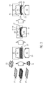
- an illustration of the steps required for producing the composite material employed according to a further embodiment of the method for manufacturing an overhead storage compartment for an aircraft cabin according to the present invention, and
- Fig. 4
- an illustration of the steps required for producing the sandwich material employed according to yet a further embodiment of the method for manufacturing an overhead storage compartment for an aircraft cabin according to the present invention.
- As shown in
Fig. 1 , the method for manufacturing an overhead storage compartment 1 for an aircraft cabin requires providing a shell part 3, afirst end wall 5 and a second end wall 7, and assembling the shell part 3 and the first andsecond end walls 5, 7. The shell part 3 is curved and extends along a longitudinal axis 9 between afirst end 11 and asecond end 13, such that the shell part 3 partially surrounds aninterior space 15. The shell part 3 has a first edge 17 at thefirst end 11 and asecond edge 19 at thesecond end 13. The first edge 17 and thesecond edge 19 run transversely to the longitudinal axis 9. The first andsecond end walls 5, 7 are generally flat and extend transversely to the longitudinal axis 9. - When the shell part 3 and the first and
second end walls 5, 7 are assembled, the first edge 17 is attached to thefirst end wall 5, and thesecond edge 19 is attached to the second end wall 7, such that the shell part 3, thefirst end wall 5 and the second end wall 7 together at least partially surround theinterior space 15. Thefirst end wall 5 comprises afirst groove 21 formed complementary to the first edge 17 and the second end wall 7 comprises asecond groove 23 formed complementary to thesecond edge 19. The first edge 17 is attached to thefirst end wall 5 by inserting the first edge 17 into thefirst groove 21 so that the first edge 17 extends in thefirst groove 21 in a form fit manner. Thesecond edge 19 is attached to the second end wall 7 by inserting thesecond edge 19 into thesecond groove 23 so that thesecond edge 19 extends in thesecond groove 23 in a form fit manner. The first edge 17 is additionally attached in thefirst groove 21 by an adhesive, and thesecond edge 19 is additionally attached in thesecond groove 23 by an adhesive. - In the embodiment shown in
Fig. 1 , the shell part 3 and the first andsecond end walls 5, 7 are preproduced and precured before being assembled. However, it is also possible that the shell part 3 and the first andsecond end walls 5, 7 are formed and cured integrally. -
Fig. 2 shows an overhead storage compartment 1 for an aircraft cabin which has been produced by a method according to the present invention, in particular by a method similar to the one described in connection withFig. 1 . The overhead storage compartment 1 comprises a shell part 3 extending along a longitudinal axis 9 between afirst end 11 and asecond end 13, wherein the shell part 3 partially surrounds aninterior space 15. The shell part 3 has a first edge 17 at thefirst end 11 and asecond edge 19 at thesecond end 13, wherein the first edge 17 and thesecond edge 19 run transversely to the longitudinal axis 9. The overhead storage compartment 1 further comprises afirst end wall 5 and a second end wall 7. Thefirst end wall 5 comprises afirst groove 21 formed complementary to the first edge 17, and the second end wall 7 comprises asecond groove 23 formed complementary to thesecond edge 19. The first edge 17 extends into thefirst groove 21, and thesecond edge 19 extends into thesecond groove 23 in a form fit manner, so as to attach thefirst end wall 5 to the first edge 17 and the second end wall 7 to thesecond edge 19. In such a way, the shell part 3, thefirst end wall 5 and the second end wall 7 together partially surround the interior space 9. - The
first end wall 5 and the second end wall 7 of the overhead storage compartment 1 as shown inFig. 1 and inFig. 2 comprise an undirected long fiber reinforced plastic material, in particular a sheet molding compound (SMC) material. Specifically, the first andsecond end walls 5, 7 are formed of acomposite material 25 including afirst layer 27 of the undirected long fiber reinforced plastic material and asecond layer 29 of a unidirectional continuous fiber reinforced plastic material. In particular, thecomposite material 25 comprises severalsecond layers 29 sandwiched between twofirst layers 27. - As shown in
Fig. 3 , thecomposite material 25 of the first andsecond end walls 5, 7 can be produced by a pressing process under the application of pressure and heat, specifically by an impact extrusion process. As shown inFig. 3 , two firstsemi-finished layers 27' of an undirected long fiber reinforced plastic molding material and several second semi-finished layers 29' of a unidirectional continuous fiber reinforced plastic molding material are placed against one another such that the second semi-finished layers 29' are sandwiched between the firstsemi-finished layers 27', thereby forming a semi-finished composite product 25'. The semi-finished composite product 25' is then deformed in apress device 33, specifically in an extrusion press, under the application of predefined pressure and temperature profiles. - One alternative for the
composite material 25 of the first andsecond end walls 5, 7 is asandwich material 35 comprising twocover layers 37 of the undirected long fiber reinforced plastic material and acore layer 39 of a foam material sandwiched between the cover layers 37. As shown inFig. 4 , thesandwich material 35 of the first andsecond end walls 5, 7 can be produced by a pressing process under the application of pressure and heat, specifically by an impact extrusion process.Fig. 4 shows that two semi-finished cover layers 37' of undirected long fiber reinforced plastic molding material and asemi-finished core layer 39' of foam material are placed against one another such that thesemi-finished core layer 39' is sandwiched between the semi-finished cover layers 37', thereby forming a semi-finished sandwich product 35'. The semi-finished sandwich product 35' is then deformed in apress device 33, specifically in an extrusion press, under application of a predefined pressure profile and a predefined temperature profile. - In case of both the pressing process shown in
Fig. 3 and the pressing process shown inFig. 4 , thepress device 33 comprises afirst tool part 41 and asecond tool part 43 together forming acavity 45 in which the semi-finished composite or sandwich product 25', 35' is received. In order to apply pressure and deform the semi-finished composite or sandwich product 25', 35', the first andsecond tool parts Fig. 4 , thepress device 33 preferably further comprises adistance control device 46 in the form of a stopper, defining the minimum distance between the first andsecond tool parts distance control device 46 is configured such that at a minimum distance between the first andsecond tool parts 41, 43 a mold pressure is between a minimum processing pressure of the semi-finished cover layers 37' and a limit pressure maximum allowable for thesemi-finished core layer 39' not to be destroyed. - A third possible alternative for the material of the first and
second end walls 5, 7 would be ahomogeneous material 47 including only the undirected long fiber reinforced plastic material without any further material component. Thehomogeneous material 47 can be produced by a not illustrated pressing process similar to the ones shown inFig. 3 andFig. 4 under the application of pressure and heat, specifically by an impact extrusion process. The pressing process requires that a semi-finished product of undirected long fiber reinforced plastic molding material is deformed in apress device 33, specifically in an extrusion press, under application of predefined pressure and temperature profiles. - In the embodiment shown in
Fig. 1 the shell part 3 is formed of ahoneycomb sandwich material 49 comprising a honeycomb core layer sandwiched between fiber composite cover layers. Alternatively, the shell part 3 can also be formed of any of the before-describedcomposite material 25,sandwich material 35 andhomogeneous material 47 used for the first andsecond end walls 5, 7. For instance, in the embodiment shown inFig. 2 the shell part 3 is formed of thehomogeneous material 47. Specifically in the case of thehomogeneous material 47, but also in the case of thecomposite material 25 and thesandwich material 35,reinforcement ribs 51 may be provided at a surface of the shell part 3, thefirst end wall 5 or the second end wall 7.Such reinforcement ribs 51 are illustrated e.g. inFig. 2 at the shell part as well as inFig. 3 andFig. 4 . - In any of the afore-described embodiments, one or more metal inserts 53, such as fitting parts, or one or more semi-finished reinforcement layers 55 of preimpregnated unidirectional continuous fibers, such as tailored fiber placement patches, can be included in the semi-finished composite product 25', in the semi-finished sandwich product 35' and in the semi-finished product 47' before the pressing process, such that they are included in the
composite material 25, thesandwich material 35 or thehomogeneous material 47 already when the material is readily produced, i. e. before the overhead storage compartment 1 is assembled.Such metal insert 53 and suchsemi-finished reinforcement layer 55 are illustrated inFig. 3 . - By the method according to the present invention a considerably simple and resistant overhead storage compartment 1 for an aircraft cabin can be manufactured in a very simple and fast way.
Claims (15)
- A method for manufacturing an overhead storage compartment (1) for an aircraft cabin, the method comprising the steps of- Providing a shell part (3) extending along a longitudinal axis (9) between a first end (11) and a second end (13), wherein the shell part (3) partially surrounds an interior space (15), wherein the shell part (3) has a first edge (17) at the first end (11) and a second edge (19) at the second end (13), wherein the first edge (17) and the second edge (19) run transverse to the longitudinal axis (9),- Providing a first end wall (5) and a second end wall (7),- Assembling the shell part (3) and the first and second end walls (5, 7), wherein the first edge (17) is attached to the first end wall (5) and the second edge (19) is attached to the second end wall (7), such that the shell part (3), the first end wall (5) and the second end wall (7) together at least partially surround the interior space (15),characterized in that
the first end wall (5) and/or the second end wall (7) comprise an undirected long fiber reinforced plastic material. - The method according to claim 1, wherein the first end wall (5) comprises a first groove (21) formed so as to receive the first edge (17),wherein the second end wall (7) comprises a second groove (23) formed so as to receive the second edge (19),wherein the first edge (17) is attached to the first end wall (5) by inserting the first edge (17) into the first groove (21), andwherein the second edge (19) is attached to the second end wall (7) by inserting the second edge (19) into the second groove (23).
- The method according to claim 1 or 2, wherein the first end wall (5) and/or the second end wall (7) is formed of a composite material (25) comprising at least one first layer (27) of the undirected long fiber reinforced plastic material and at least one second layer (29) of a unidirectional continuous fiber reinforced plastic material.
- The method according to claim 3, wherein the composite material (25) is produced by a pressing process under application of pressure and heat,wherein at least one first semifinished layer (27') of undirected long fiber reinforced plastic molding material and at least one second semifinished layer (29') of a unidirectional continuous fiber reinforced plastic molding material are placed against one another, thereby forming a semifinished composite product (25'), which is then deformed in a press device (33) under the application of predefined pressure and temperature profiles.
- The method according to claim 1 or 2, wherein the first end wall (5) and/or the second end wall (7) is formed of a sandwich material (35) comprising at least two cover layers (37) of the undirected long fiber reinforced plastic material and a core layer (39) of a foam material sandwiched between the cover layers (37).
- The method according to claim 5, wherein the sandwich material (35) is produced by a pressing process under application of pressure and heat,wherein two semifinished cover layers (37') of undirected long fiber reinforced plastic molding material and a semifinished core layer (39') of foam material are placed against one another such that the semifinished core layer (39') is sandwiched between the semifinished cover layers (37'), thereby forming a semifinished sandwich product (35'), which is then deformed in a press device (33) under application of predefined pressure and temperature profiles.
- The method according to claim 6, wherein the press device (33) comprises a first tool part (41) and a second tool part (43),wherein the first and second tool parts (41, 43) together form a cavity (45) in which the semifinished sandwich product (35') is received,wherein the first and second tool parts (41, 43) are moved relatively against one another in order to press together and deform the semifinished sandwich product (35'),wherein the press device (33) comprises a distance control device (46) defining the minimum distance between the first and second tool parts (41, 43), andwherein the distance control device (46) is configured such that at a minimum distance between the first and second tool parts (41, 43) a mold pressure is between a minimum processing pressure of the semifinished cover layers (37') and a limit pressure maximum allowable for the semifinished core layer (39') not to be destroyed.
- The method according to claim 1 or 2, wherein the first end wall (5) and/or the second end wall (7) is formed of a homogeneous material (47) including the undirected long fiber reinforced plastic material.
- The method according to claim 8, wherein the homogeneous material (47) is produced by a pressing process under application of pressure and heat,wherein a semifinished product (47') of undirected long fiber reinforced plastic molding material is deformed in a press device (33) under application of predefined pressure and temperature profiles.
- The method according to any of claim 1 to 9, wherein the shell part (3) is formed of a honeycomb sandwich material (49) comprising a honeycomb core layer sandwiched between fiber composite cover layers.
- The method according to any of claim 1 to 9, wherein the shell part (3) is formed of the same material as the first end wall (5) and/or the second end wall (7).
- The method according to any of claim 1 to 11, wherein one or more reinforcement ribs (51) are provided at a surface of the shell part (3) and/or of the first end wall (5) and/or of the second end wall (7).
- The method according to any of claims 4, 6 and 9 or any claim dependent from any of claims 4, 6 and 9, wherein one or more metal inserts (53) and/or one or more semi-finished reinforcement layers (55) of preimpregnated unidirectional continuous fibers are included in the semi-finished composite product (25'), in the semifinished sandwich product (35') and in the semifinished product (47') before the pressing process.
- An overhead storage compartment (1) for an aircraft cabin, comprisinga shell part (3) extending along a longitudinal axis (9) between a first end (11) and a second end (13), wherein the shell part (3) partially surrounds an interior space (15), wherein the shell part (3) has a first edge (17) at the first end (11) and a second edge (19) at the second end (13), wherein the first edge (17) and the second edge (19) run transverse to the longitudinal axis (9), anda first end wall (5) and a second end wall (7), wherein the first end wall (5) is attached to the first edge (17) and the second end wall (7) is attached to the second edge (19), such that the shell part (3), the first end wall (5) and the second end wall (7) together at least partially surround the interior space (15),characterized in that
the first end wall (5) and/or the second end wall (7) comprise an undirected long fiber reinforced plastic material. - The overhead storage compartment according to claim 14, wherein the first end wall (5) comprises a first groove (21) formed so as to receive the first edge (17),wherein the second end wall (7) comprises a second groove (23) formed so as to receive the second edge (19), andwherein the first edge (17) extends into the first groove (21) and the second edge (19) extends into the second groove (23).
Priority Applications (2)
| Application Number | Priority Date | Filing Date | Title |
|---|---|---|---|
| EP16172979.3A EP3251819B1 (en) | 2016-06-03 | 2016-06-03 | A method for manufacturing an overhead storage compartment for an aircraft cabin |
| US15/611,843 US10766621B2 (en) | 2016-06-03 | 2017-06-02 | Method for manufacturing an overhead storage compartment for an aircraft cabin |
Applications Claiming Priority (1)
| Application Number | Priority Date | Filing Date | Title |
|---|---|---|---|
| EP16172979.3A EP3251819B1 (en) | 2016-06-03 | 2016-06-03 | A method for manufacturing an overhead storage compartment for an aircraft cabin |
Publications (2)
| Publication Number | Publication Date |
|---|---|
| EP3251819A1 true EP3251819A1 (en) | 2017-12-06 |
| EP3251819B1 EP3251819B1 (en) | 2021-09-29 |
Family
ID=56116277
Family Applications (1)
| Application Number | Title | Priority Date | Filing Date |
|---|---|---|---|
| EP16172979.3A Active EP3251819B1 (en) | 2016-06-03 | 2016-06-03 | A method for manufacturing an overhead storage compartment for an aircraft cabin |
Country Status (2)
| Country | Link |
|---|---|
| US (1) | US10766621B2 (en) |
| EP (1) | EP3251819B1 (en) |
Cited By (5)
| Publication number | Priority date | Publication date | Assignee | Title |
|---|---|---|---|---|
| CN109018366A (en) * | 2018-08-07 | 2018-12-18 | 晨龙飞机(荆门)有限公司 | A kind of passenger plane luggage carrier |
| DE102017117274A1 (en) * | 2017-07-31 | 2019-01-31 | Airbus Operations Gmbh | Luggage compartment for hull or ceiling installation in a vehicle and method for making such a luggage compartment |
| WO2019240976A1 (en) * | 2018-06-11 | 2019-12-19 | Microsoft Technology Licensing, Llc | Housing for mounting of components in head mounted display |
| RU2714376C1 (en) * | 2019-04-17 | 2020-02-14 | Олег Александрович Скворцов | Method for manufacturing a reusable container and a reusable container |
| DE102021121360A1 (en) | 2021-08-17 | 2023-02-23 | Diehl Aviation Laupheim Gmbh | Bonding of aircraft interior panels |
Families Citing this family (5)
| Publication number | Priority date | Publication date | Assignee | Title |
|---|---|---|---|---|
| JP7249404B2 (en) * | 2019-03-29 | 2023-03-30 | 川崎重工業株式会社 | Composite material panel structure and manufacturing method thereof |
| US11945587B2 (en) | 2019-10-03 | 2024-04-02 | Mhi Rj Aviation Ulc | Aircraft overhead luggage bin and method of modifying same |
| JP2024088819A (en) * | 2021-03-09 | 2024-07-03 | 帝人株式会社 | Manufacturing method of molded body |
| EP4438476B1 (en) | 2023-03-29 | 2026-03-11 | Airbus Operations GmbH | Lightweight overhead stowage compartment and method of installing the same |
| EP4549138A1 (en) * | 2023-11-03 | 2025-05-07 | B/E Aerospace Inc. | Aircarft interior monument |
Citations (3)
| Publication number | Priority date | Publication date | Assignee | Title |
|---|---|---|---|---|
| US5785202A (en) * | 1992-02-20 | 1998-07-28 | Fischer Advanced Composite Components Gmbh | Stowage container for the use in aircraft |
| US5900300A (en) * | 1997-07-02 | 1999-05-04 | Slaven; John P. | High modulus and stiffness polymer foam/GMT composites |
| US20050040287A1 (en) * | 2001-10-09 | 2005-02-24 | Stephan Walter Alfred | Overhead luggage container, particularly for airplanes |
Family Cites Families (1)
| Publication number | Priority date | Publication date | Assignee | Title |
|---|---|---|---|---|
| WO2015183248A1 (en) * | 2014-05-28 | 2015-12-03 | The Boeing Company | Sandwich panel joints and methods for joining sandwich panels |
-
2016
- 2016-06-03 EP EP16172979.3A patent/EP3251819B1/en active Active
-
2017
- 2017-06-02 US US15/611,843 patent/US10766621B2/en active Active
Patent Citations (3)
| Publication number | Priority date | Publication date | Assignee | Title |
|---|---|---|---|---|
| US5785202A (en) * | 1992-02-20 | 1998-07-28 | Fischer Advanced Composite Components Gmbh | Stowage container for the use in aircraft |
| US5900300A (en) * | 1997-07-02 | 1999-05-04 | Slaven; John P. | High modulus and stiffness polymer foam/GMT composites |
| US20050040287A1 (en) * | 2001-10-09 | 2005-02-24 | Stephan Walter Alfred | Overhead luggage container, particularly for airplanes |
Cited By (6)
| Publication number | Priority date | Publication date | Assignee | Title |
|---|---|---|---|---|
| DE102017117274A1 (en) * | 2017-07-31 | 2019-01-31 | Airbus Operations Gmbh | Luggage compartment for hull or ceiling installation in a vehicle and method for making such a luggage compartment |
| WO2019240976A1 (en) * | 2018-06-11 | 2019-12-19 | Microsoft Technology Licensing, Llc | Housing for mounting of components in head mounted display |
| CN109018366A (en) * | 2018-08-07 | 2018-12-18 | 晨龙飞机(荆门)有限公司 | A kind of passenger plane luggage carrier |
| CN109018366B (en) * | 2018-08-07 | 2020-04-03 | 晨龙飞机(荆门)有限公司 | Passenger plane luggage rack |
| RU2714376C1 (en) * | 2019-04-17 | 2020-02-14 | Олег Александрович Скворцов | Method for manufacturing a reusable container and a reusable container |
| DE102021121360A1 (en) | 2021-08-17 | 2023-02-23 | Diehl Aviation Laupheim Gmbh | Bonding of aircraft interior panels |
Also Published As
| Publication number | Publication date |
|---|---|
| US20170349288A1 (en) | 2017-12-07 |
| EP3251819B1 (en) | 2021-09-29 |
| US10766621B2 (en) | 2020-09-08 |
Similar Documents
| Publication | Publication Date | Title |
|---|---|---|
| EP3251819B1 (en) | A method for manufacturing an overhead storage compartment for an aircraft cabin | |
| US9630654B2 (en) | Body structural element and method for producing a body structural element | |
| US9669581B2 (en) | Method for manufacturing an aeronautical torsion box, torsion box and tool for manufacturing an aeronautical torsion box | |
| US9545761B2 (en) | Tool sleeve for mold die | |
| DE102011076082B4 (en) | Rotor blade for wind turbines made of textile-reinforced thermoplastic semi-finished products and process for the production | |
| EP3677397B1 (en) | Composite part | |
| US11027499B2 (en) | Method for connecting hollow profiles | |
| CN101500787A (en) | Improved composite resin window frame constructions for airplanes | |
| NL2012457B1 (en) | Primary structure connecting element for aircraft and method for manufacturing the connecting element. | |
| EP2849932A1 (en) | Over-molding of load-bearing composite structures | |
| US20100193114A1 (en) | Apparatus and Method for Forming Fibre Reinforced Composite Structures | |
| US20170129545A1 (en) | Frame structure with at least one console for connecting further components, method for producing and motor vehicle body | |
| US20160176085A1 (en) | Method and system for producing composite structures | |
| EP1800842B1 (en) | A method of manufacturing an elongate structural element configured for stiffening a shell structure, and a method for manufacturing a rigid shell structure integrated with at least one elongate stiffening element | |
| US20170361781A1 (en) | Process for manufacturing a motor vehicle part | |
| EP2234793B1 (en) | Piece made of composite material with areas of different thickness | |
| US20140248143A1 (en) | Monolithic fan cowl of an aircraft engine and a manufacturing method thereof | |
| EP1972430A1 (en) | Method for producing structures from composite materials, including embedded precured tools | |
| RU2595207C2 (en) | Aircraft frame from composite material | |
| JP2009500188A (en) | Method for manufacturing a substantially shell-shaped component | |
| CA3040088C (en) | Method for producing a reinforcing component and component | |
| US6565690B1 (en) | Process for manufacturing structures of composite material | |
| US20160318262A1 (en) | Process for producing a plastic part having a foam core | |
| US11230069B2 (en) | Tool for forming a composite member | |
| US20240278511A1 (en) | Hybrid tooling structures of additively manufactured thermoplastics reinforced with rigid metal supports and methods for the design and manufacture thereof |
Legal Events
| Date | Code | Title | Description |
|---|---|---|---|
| PUAI | Public reference made under article 153(3) epc to a published international application that has entered the european phase |
Free format text: ORIGINAL CODE: 0009012 |
|
| STAA | Information on the status of an ep patent application or granted ep patent |
Free format text: STATUS: THE APPLICATION HAS BEEN PUBLISHED |
|
| AK | Designated contracting states |
Kind code of ref document: A1 Designated state(s): AL AT BE BG CH CY CZ DE DK EE ES FI FR GB GR HR HU IE IS IT LI LT LU LV MC MK MT NL NO PL PT RO RS SE SI SK SM TR |
|
| AX | Request for extension of the european patent |
Extension state: BA ME |
|
| STAA | Information on the status of an ep patent application or granted ep patent |
Free format text: STATUS: REQUEST FOR EXAMINATION WAS MADE |
|
| 17P | Request for examination filed |
Effective date: 20180606 |
|
| RBV | Designated contracting states (corrected) |
Designated state(s): AL AT BE BG CH CY CZ DE DK EE ES FI FR GB GR HR HU IE IS IT LI LT LU LV MC MK MT NL NO PL PT RO RS SE SI SK SM TR |
|
| GRAP | Despatch of communication of intention to grant a patent |
Free format text: ORIGINAL CODE: EPIDOSNIGR1 |
|
| STAA | Information on the status of an ep patent application or granted ep patent |
Free format text: STATUS: GRANT OF PATENT IS INTENDED |
|
| INTG | Intention to grant announced |
Effective date: 20210413 |
|
| GRAS | Grant fee paid |
Free format text: ORIGINAL CODE: EPIDOSNIGR3 |
|
| GRAA | (expected) grant |
Free format text: ORIGINAL CODE: 0009210 |
|
| STAA | Information on the status of an ep patent application or granted ep patent |
Free format text: STATUS: THE PATENT HAS BEEN GRANTED |
|
| AK | Designated contracting states |
Kind code of ref document: B1 Designated state(s): AL AT BE BG CH CY CZ DE DK EE ES FI FR GB GR HR HU IE IS IT LI LT LU LV MC MK MT NL NO PL PT RO RS SE SI SK SM TR |
|
| REG | Reference to a national code |
Ref country code: GB Ref legal event code: FG4D |
|
| REG | Reference to a national code |
Ref country code: DE Ref legal event code: R096 Ref document number: 602016064239 Country of ref document: DE |
|
| REG | Reference to a national code |
Ref country code: CH Ref legal event code: EP Ref country code: AT Ref legal event code: REF Ref document number: 1433850 Country of ref document: AT Kind code of ref document: T Effective date: 20211015 |
|
| REG | Reference to a national code |
Ref country code: IE Ref legal event code: FG4D |
|
| REG | Reference to a national code |
Ref country code: LT Ref legal event code: MG9D |
|
| PG25 | Lapsed in a contracting state [announced via postgrant information from national office to epo] |
Ref country code: FI Free format text: LAPSE BECAUSE OF FAILURE TO SUBMIT A TRANSLATION OF THE DESCRIPTION OR TO PAY THE FEE WITHIN THE PRESCRIBED TIME-LIMIT Effective date: 20210929 Ref country code: NO Free format text: LAPSE BECAUSE OF FAILURE TO SUBMIT A TRANSLATION OF THE DESCRIPTION OR TO PAY THE FEE WITHIN THE PRESCRIBED TIME-LIMIT Effective date: 20211229 Ref country code: BG Free format text: LAPSE BECAUSE OF FAILURE TO SUBMIT A TRANSLATION OF THE DESCRIPTION OR TO PAY THE FEE WITHIN THE PRESCRIBED TIME-LIMIT Effective date: 20211229 Ref country code: LT Free format text: LAPSE BECAUSE OF FAILURE TO SUBMIT A TRANSLATION OF THE DESCRIPTION OR TO PAY THE FEE WITHIN THE PRESCRIBED TIME-LIMIT Effective date: 20210929 Ref country code: RS Free format text: LAPSE BECAUSE OF FAILURE TO SUBMIT A TRANSLATION OF THE DESCRIPTION OR TO PAY THE FEE WITHIN THE PRESCRIBED TIME-LIMIT Effective date: 20210929 Ref country code: SE Free format text: LAPSE BECAUSE OF FAILURE TO SUBMIT A TRANSLATION OF THE DESCRIPTION OR TO PAY THE FEE WITHIN THE PRESCRIBED TIME-LIMIT Effective date: 20210929 Ref country code: HR Free format text: LAPSE BECAUSE OF FAILURE TO SUBMIT A TRANSLATION OF THE DESCRIPTION OR TO PAY THE FEE WITHIN THE PRESCRIBED TIME-LIMIT Effective date: 20210929 |
|
| REG | Reference to a national code |
Ref country code: NL Ref legal event code: MP Effective date: 20210929 |
|
| REG | Reference to a national code |
Ref country code: AT Ref legal event code: MK05 Ref document number: 1433850 Country of ref document: AT Kind code of ref document: T Effective date: 20210929 |
|
| PG25 | Lapsed in a contracting state [announced via postgrant information from national office to epo] |
Ref country code: LV Free format text: LAPSE BECAUSE OF FAILURE TO SUBMIT A TRANSLATION OF THE DESCRIPTION OR TO PAY THE FEE WITHIN THE PRESCRIBED TIME-LIMIT Effective date: 20210929 Ref country code: GR Free format text: LAPSE BECAUSE OF FAILURE TO SUBMIT A TRANSLATION OF THE DESCRIPTION OR TO PAY THE FEE WITHIN THE PRESCRIBED TIME-LIMIT Effective date: 20211230 |
|
| PG25 | Lapsed in a contracting state [announced via postgrant information from national office to epo] |
Ref country code: AT Free format text: LAPSE BECAUSE OF FAILURE TO SUBMIT A TRANSLATION OF THE DESCRIPTION OR TO PAY THE FEE WITHIN THE PRESCRIBED TIME-LIMIT Effective date: 20210929 |
|
| PG25 | Lapsed in a contracting state [announced via postgrant information from national office to epo] |
Ref country code: IS Free format text: LAPSE BECAUSE OF FAILURE TO SUBMIT A TRANSLATION OF THE DESCRIPTION OR TO PAY THE FEE WITHIN THE PRESCRIBED TIME-LIMIT Effective date: 20220129 Ref country code: SK Free format text: LAPSE BECAUSE OF FAILURE TO SUBMIT A TRANSLATION OF THE DESCRIPTION OR TO PAY THE FEE WITHIN THE PRESCRIBED TIME-LIMIT Effective date: 20210929 Ref country code: RO Free format text: LAPSE BECAUSE OF FAILURE TO SUBMIT A TRANSLATION OF THE DESCRIPTION OR TO PAY THE FEE WITHIN THE PRESCRIBED TIME-LIMIT Effective date: 20210929 Ref country code: PT Free format text: LAPSE BECAUSE OF FAILURE TO SUBMIT A TRANSLATION OF THE DESCRIPTION OR TO PAY THE FEE WITHIN THE PRESCRIBED TIME-LIMIT Effective date: 20220131 Ref country code: PL Free format text: LAPSE BECAUSE OF FAILURE TO SUBMIT A TRANSLATION OF THE DESCRIPTION OR TO PAY THE FEE WITHIN THE PRESCRIBED TIME-LIMIT Effective date: 20210929 Ref country code: NL Free format text: LAPSE BECAUSE OF FAILURE TO SUBMIT A TRANSLATION OF THE DESCRIPTION OR TO PAY THE FEE WITHIN THE PRESCRIBED TIME-LIMIT Effective date: 20210929 Ref country code: ES Free format text: LAPSE BECAUSE OF FAILURE TO SUBMIT A TRANSLATION OF THE DESCRIPTION OR TO PAY THE FEE WITHIN THE PRESCRIBED TIME-LIMIT Effective date: 20210929 Ref country code: EE Free format text: LAPSE BECAUSE OF FAILURE TO SUBMIT A TRANSLATION OF THE DESCRIPTION OR TO PAY THE FEE WITHIN THE PRESCRIBED TIME-LIMIT Effective date: 20210929 Ref country code: CZ Free format text: LAPSE BECAUSE OF FAILURE TO SUBMIT A TRANSLATION OF THE DESCRIPTION OR TO PAY THE FEE WITHIN THE PRESCRIBED TIME-LIMIT Effective date: 20210929 Ref country code: AL Free format text: LAPSE BECAUSE OF FAILURE TO SUBMIT A TRANSLATION OF THE DESCRIPTION OR TO PAY THE FEE WITHIN THE PRESCRIBED TIME-LIMIT Effective date: 20210929 |
|
| REG | Reference to a national code |
Ref country code: DE Ref legal event code: R097 Ref document number: 602016064239 Country of ref document: DE |
|
| PG25 | Lapsed in a contracting state [announced via postgrant information from national office to epo] |
Ref country code: DK Free format text: LAPSE BECAUSE OF FAILURE TO SUBMIT A TRANSLATION OF THE DESCRIPTION OR TO PAY THE FEE WITHIN THE PRESCRIBED TIME-LIMIT Effective date: 20210929 |
|
| PLBE | No opposition filed within time limit |
Free format text: ORIGINAL CODE: 0009261 |
|
| STAA | Information on the status of an ep patent application or granted ep patent |
Free format text: STATUS: NO OPPOSITION FILED WITHIN TIME LIMIT |
|
| 26N | No opposition filed |
Effective date: 20220630 |
|
| PG25 | Lapsed in a contracting state [announced via postgrant information from national office to epo] |
Ref country code: SI Free format text: LAPSE BECAUSE OF FAILURE TO SUBMIT A TRANSLATION OF THE DESCRIPTION OR TO PAY THE FEE WITHIN THE PRESCRIBED TIME-LIMIT Effective date: 20210929 |
|
| PG25 | Lapsed in a contracting state [announced via postgrant information from national office to epo] |
Ref country code: MC Free format text: LAPSE BECAUSE OF FAILURE TO SUBMIT A TRANSLATION OF THE DESCRIPTION OR TO PAY THE FEE WITHIN THE PRESCRIBED TIME-LIMIT Effective date: 20210929 Ref country code: IT Free format text: LAPSE BECAUSE OF FAILURE TO SUBMIT A TRANSLATION OF THE DESCRIPTION OR TO PAY THE FEE WITHIN THE PRESCRIBED TIME-LIMIT Effective date: 20210929 |
|
| REG | Reference to a national code |
Ref country code: CH Ref legal event code: PL |
|
| REG | Reference to a national code |
Ref country code: BE Ref legal event code: MM Effective date: 20220630 |
|
| PG25 | Lapsed in a contracting state [announced via postgrant information from national office to epo] |
Ref country code: LU Free format text: LAPSE BECAUSE OF NON-PAYMENT OF DUE FEES Effective date: 20220603 Ref country code: LI Free format text: LAPSE BECAUSE OF NON-PAYMENT OF DUE FEES Effective date: 20220630 Ref country code: IE Free format text: LAPSE BECAUSE OF NON-PAYMENT OF DUE FEES Effective date: 20220603 Ref country code: CH Free format text: LAPSE BECAUSE OF NON-PAYMENT OF DUE FEES Effective date: 20220630 |
|
| PG25 | Lapsed in a contracting state [announced via postgrant information from national office to epo] |
Ref country code: BE Free format text: LAPSE BECAUSE OF NON-PAYMENT OF DUE FEES Effective date: 20220630 |
|
| PG25 | Lapsed in a contracting state [announced via postgrant information from national office to epo] |
Ref country code: HU Free format text: LAPSE BECAUSE OF FAILURE TO SUBMIT A TRANSLATION OF THE DESCRIPTION OR TO PAY THE FEE WITHIN THE PRESCRIBED TIME-LIMIT; INVALID AB INITIO Effective date: 20160603 |
|
| PG25 | Lapsed in a contracting state [announced via postgrant information from national office to epo] |
Ref country code: SM Free format text: LAPSE BECAUSE OF FAILURE TO SUBMIT A TRANSLATION OF THE DESCRIPTION OR TO PAY THE FEE WITHIN THE PRESCRIBED TIME-LIMIT Effective date: 20210929 Ref country code: MK Free format text: LAPSE BECAUSE OF FAILURE TO SUBMIT A TRANSLATION OF THE DESCRIPTION OR TO PAY THE FEE WITHIN THE PRESCRIBED TIME-LIMIT Effective date: 20210929 Ref country code: CY Free format text: LAPSE BECAUSE OF FAILURE TO SUBMIT A TRANSLATION OF THE DESCRIPTION OR TO PAY THE FEE WITHIN THE PRESCRIBED TIME-LIMIT Effective date: 20210929 |
|
| PG25 | Lapsed in a contracting state [announced via postgrant information from national office to epo] |
Ref country code: TR Free format text: LAPSE BECAUSE OF FAILURE TO SUBMIT A TRANSLATION OF THE DESCRIPTION OR TO PAY THE FEE WITHIN THE PRESCRIBED TIME-LIMIT Effective date: 20210929 |
|
| PG25 | Lapsed in a contracting state [announced via postgrant information from national office to epo] |
Ref country code: MT Free format text: LAPSE BECAUSE OF FAILURE TO SUBMIT A TRANSLATION OF THE DESCRIPTION OR TO PAY THE FEE WITHIN THE PRESCRIBED TIME-LIMIT Effective date: 20210929 |
|
| PGFP | Annual fee paid to national office [announced via postgrant information from national office to epo] |
Ref country code: DE Payment date: 20250618 Year of fee payment: 10 |
|
| PGFP | Annual fee paid to national office [announced via postgrant information from national office to epo] |
Ref country code: GB Payment date: 20250618 Year of fee payment: 10 |
|
| PGFP | Annual fee paid to national office [announced via postgrant information from national office to epo] |
Ref country code: FR Payment date: 20250625 Year of fee payment: 10 |